Instrument Transformer Theory and Testing - Powermetrix · Instrument Transformer? Instrument...
50
1 Instrument Transformer Theory and Testing Steve Hudson, PE Engineering Manager 10737 Lexington Drive Knoxville, TN 37932 Phone: (865) 966-5856 www.powermetrix.com
Transcript of Instrument Transformer Theory and Testing - Powermetrix · Instrument Transformer? Instrument...

1
Instrument Transformer Theory and Testing
Steve Hudson, PE Engineering Manager
10737 Lexington Drive Knoxville, TN 37932
Phone: (865) 966-5856
www.powermetrix.com

2
What is a Transformer?
• A TRANSFORMER is a device used to change the voltage levels of electricity to facilitate the transfer of electricity from generating stations to customers. A step-up transformer increases the voltage while a step-down transformer decreases it. www.duquesnelight.com/understandingelectricityupdate/electricterms.html

3
Basic Transformer Theory
• Vp = primary voltage• Ip = primary current• Np = primary turns• Pp = primary power• Vs = secondary voltage• Is = secondary current• Ns = secondary turns• Ps = secondary power
VpNp
NsVs =
IpNs
NpIs =
IsVsPsIpVpPp •==•=
This is true for an IDEAL transformer!

4
What is anInstrument Transformer?
Instrument Transformers convert signal levels from dangerous (high voltage) or inconvenient (high current, or current at high voltage) to levels appropriate for metering.
There are two fundamental types:
CT’s (Current Transformers)
PT’s (Potential Transformers)

5
Potential Transformers (PT’s)
• PT’s step down high voltages to the voltage needed by the meter (usually 120V occasionally 67V).
• They come in many shapes and sizes for different applications
• They work exactly as you would expect them to: Vo=Vi•(Ns/Np).
• They come in various power ratings expressed in VA.
• They come in various accuracy classes, however the 0.3% accuracy class is generally used in North America.

6
Potential Transformers (PT’s)
• PTs are available in Accuracy Classes 1.2 Pecent 0.6 Percent 0.3 Percent
• Burdens are expressed in VA W 12.5 VA X 25.0 VA M 35.0 VA Y 75.0 VA Z 200.0 VA ZZ 400.0 VA

7
Potential Transformers (PT’s)
• 600V Type 240/416 2:1 288/500 2.4:1 300/520 2.5:1 480/480 4:1 600/600 5:1
• 5K Type 2400/4160 20:1 4200/7280 35:1 4800/8320 40:1
• Medium Voltage 7200/12470 60:1 8400/14560 70:1 12000/20800 100:1 14400/24940 120:1 18000/18000 150:1 24000/24000 200:1 27600/27600 240:1 34500/34500 300:1
• High Voltage Operate quite differently May have no direct connection
to transformer

8
Current Transformers (CT’s)
• CT’s allow the measurement of high currents at potentially high voltages.
• They come in many shapes and sizes for different applications
• They are potentially extremely dangerous.
They can kill you!

9
Current Transformers (CT’s)
10
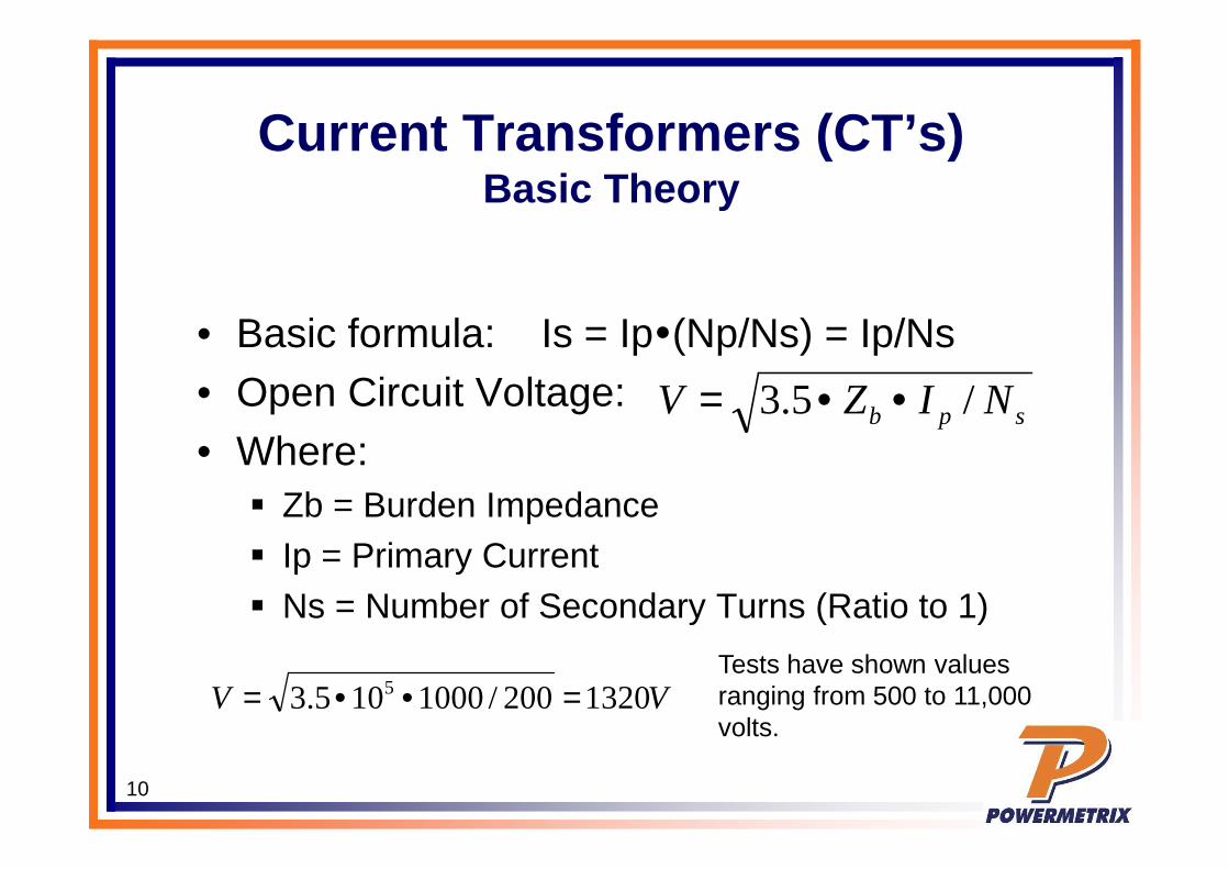
Current Transformers (CT’s)Basic Theory
• Basic formula: Is = Ip(Np/Ns) = Ip/Ns• Open Circuit Voltage:• Where:
Zb = Burden Impedance Ip = Primary Current Ns = Number of Secondary Turns (Ratio to 1)
spb NIZV /5.3 ••=
VV 1320200/1000105.3 5 =••=Tests have shown values ranging from 500 to 11,000 volts.

11
CT – Accuracy Class/Burden
• Most CTs used in North America are 0.3 (0.3 percent) Class devices.
• When an accuracy class is specified the maximum burden for which the device meets the class accuracy is also specified.

12
CT – Class 0.3
• Metering error shall be less than 0.3% when the CT is used at FULL RATED LOAD and with rated burden.
• Metering error shall be less than 0.6% when the CT is used between 10% and 100% of full rated load.
• Error is a combination of amplitude and phase error.

13
CT – Accuracy – Burden - Load
Meets Accuracy Spec
Meets 0.6 Spec
No Spec

14 Slide Courtesy Kent Jones, GE
0.3% ACCURACY
AC
CU
RA
CY
CL
AS
S
RATING
SECONDARY
FACTOR
CURRENT
20
4.0
15
3.02.0
10
1.0
5.02.51.00.5
.25
0.1
5%10%
50% 100% 200 300 400
0.60
0.30
0.15
0.15
0.30
0.60
0.6% ACCURACY REGION
NO ACCURACY GUARANTEED IN FRONT OF THIS LINE
0.3% @ BX.X RF 4.0
X CT TEST POINT
C20 METER TEST POINT
X X
ACTUAL
IEEE C57.13 ACCURACY
MAXIMUM CONTINUOUSAMPS (RF=4.0)
X
Accuracy Class 0.3

15
0.15% ACCURACY
AC
CU
RA
CY
CL
AS
S
RATING
SECONDARY
FACTOR
CURRENT
20
4.0
15
3.02.0
10
1.0
5.02.51.00.5
.25
0.1
5%10%
50% 100% 200 300 400
0.60
0.30
0.15
0.15
0.30
0.60 0.3% ACCURACY REGION
NO ACCURACY GUARANTEED IN FRONT OF THIS LINE
0.15 @ E0.04, 0.15 @ E0.20, 0.15 @ BX.X RF 4.0
X CT TEST POINT
C20 METER TEST POINT
X X
ACTUAL
PROPOSED IEEE C57.13.6 ACCURACY
CURRENT (RF=4.0)MAXIMUM CONTINUOUS
Slide Courtesy Kent Jones, GE
Accuracy Class 0.15

16 Slide Courtesy Kent Jones, GE
AC
CU
RA
CY
CLA
SS
RATING
SECONDARY
FACTOR
CURRENT
20
4.0
15
3.02.0
10
1.0
5.02.51.00.5
.25
0.1
5%
10%
50% 100% 200 300 400
0.60
0.30
0.15
0.15
0.30
0.60
0.15% ACCURACY REGION
NO ACCURACY GUARANTEED IN FRONT OF THIS LINE
0.15S @ E0.04, 0.15S @ E0.20, 0.15S @ BX.X RF 4.0
X CT TEST POINT
C20 METER TEST POINT
X X
ACTUAL
PROPOSED IEEE C57.13.6 ACCURACY
CURRENT (RF=4.0)MAXIMUM CONTINUOUS
X
Accuracy Class 0.15S

17
Errors with Current Transformers

18
Errors with Current Transformers
• CTs require a lot of care to insure accurate metering. Burden – Over burden reduces CT accuracy. Wiring – Faulty or improper wiring reduces
accuracy by increasing burden. Shunt – Failure to remove the safety shunt
will not keep the CT from operating but it will reduce the readings by 50-80%

19
Errors with Current Transformers
• When you see a CT spec sheet it will give you the burden at which the CT meets a specific accuracy Class

20
Errors with Current Transformers
• Many CTs are only rated at B0.1 and B0.2
• #16 wire is 4.5 mΩ/ft• #14 wire is 2.8 mΩ/ft• #12 wire is 1.8 mΩ/ft• #10 wire is 1.1 mΩ/ft• #8 wire is 0.7 mΩ/ft• 50 ft of #12 wire is
nearly 100 mΩ
21
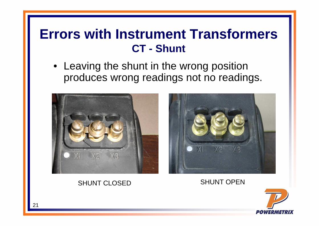
Errors with Instrument Transformers CT - Shunt
• Leaving the shunt in the wrong position produces wrong readings not no readings.
SHUNT CLOSED SHUNT OPEN

22
Errors with Instrument TransformersCT - Polarity
• Polarity of the connection matters.
• Wrong polarity means totally wrong metering.
• When PF≠0, reversed polarities may not be obvious.

23
CT Rating FactorThe MOST Misunderstood Spec
• Rating Factor has absolutely nothing to do with burden.
• If a CT has a rating factor of 4 it means that at 30°C it can be used up to 4X its label current and maintain its accuracy Class.

24
CT Rating Factor• Rating Factor is a strong
function of temperature.• If a CT has a rating factor
of 4 it means that at 30°C it can be used up to 4X its label current and maintain its accuracy Class.
• Operating temperature affects Rating Factor significantly. A CT with RF=4 at 30°C is
only RF=3 at 55°C

25
CT Testing
• Three Approaches in use today Direct RATIO measurement with applied
burdenMost accurate approach tells us exactly what we
want to knowMeasures directly the quantity we care about CT
Ratio Is more complicated to perform.

26
CT Testing
• Alternate Approaches Burden only
A compromise: tells us if circuit is stable under excess burden
Can’t give us the ratio which is what we really care about.
Admittance TestingAllows us to look for changes from previous
measurements.Doesn’t directly give ratioAccuracy typically ±5%

27
On Site CT Testing• The meter measures ONLY the voltage and current reaching the
meter terminals.
• To verify that the CT is working at the site we have to test the entire circuit.

28
CT TransformersField Verification – Full Ratio Measurement
Measure Here
Measure Here

29
CT Ratio with Burden Testing• Ratio Testing is the
preferred approach when we can gain access to the CT primary.
• Various types of probes can be used for primary side. Flex HV

30
CT Ratio with Burden Testing• Secondary
connection is made through the test switch
• Same connection that is used for the rest of the site testing.
Ratio Testing with applied burden is the most accurate and complete approach for testing at CT in service.

31
Testing Current TransformersRatio vs Applied Burden
• CT testing can be done with very high accuracy
Reference CT measured using PowerMaster with 752 clamp-on probes. Essentially NO ratio error, phase shift, or change in secondary current versus applied burden.

32
Testing Current TransformersRatio vs Applied Burden
Reference CT measured using PowerMaster with 752 clamp-on probes. Essentially NO ratio error, phase shift, or change in secondary current versus applied burden.
• CT testing can be done with very high accuracy

33
Testing Current TransformersRatio vs Applied Burden
Reference CT measured using PowerMaster with 752 clamp-on probes. Essentially NO ratio error, phase shift, or change in secondary current versus applied burden.
• CT testing can be done with very high accuracy

34
Testing Current TransformersRatio vs Applied Burden
• CTs installations can be fully verified in the field
We can verify that the ratio is correct and constant as burden changes.
Burden Class 0.1 CTs various issues: too small gauge wire, bad connections, high harmonic content.

35
Testing Current TransformersRatio vs Applied Burden
• CTs installations can be fully verified in the field
We can verify that the ratio is correct and constant as burden changes.
Burden Class 0.1 CTs

36
Testing Current TransformersRatio vs Applied Burden
• CTs installations can be fully verified in the field
CT Phase B highly harmonic load. CT Phase B harmonic load removed.
Same CT in BOTH cases.

37
Testing Current TransformersRatio vs Applied Burden
• CTs installations can be fully verified in the field
These are the waveforms and harmonics when the CT failed.

38
Testing Current TransformersRatio vs Applied Burden
• CTs installations can be fully verified in the field
Without the harmonic load this CT passed it’s test.

39
Testing Current TransformersRatio Error – In Whose Favor?
I did at CT ratio test. What does it mean when I measure a ratio of 99.68:5 on a 100:5 CT?

40
Testing Current TransformersRatio Error – In Whose Favor?
In the phase B test we measured 35.86 amps on the primary and 1.799 secondary amps.
Ratio = 5.0 * (Primary / Secondary) = 99.68If the ratio had been 100:5 and the primary was 35.86 amps we should have measured 1.793 amps on the secondary. We measured 1.799 – MORE than we should have. Therefore a tested ratio of 99.68 means that we are measuring more current than we should. This error is in our favor.

41
Testing Current TransformersRatio Error – In Whose Favor?
Suppose we add burden to the metering circuit.
Notice that the ratio increases as we apply burden. With 0.3 Ohms of burden the ratio switches from less than 100:5 to greater than 100:5. This is the point where things swing to being in favor of the customer.

42
Testing Current TransformersBurden Test Only
• If we cannot get to the primary side of the CT we can check that the output is constant as burden changes.
Burden Class 0.2 CTs can look quite bad but actually be within specs.

43
Testing Current TransformersBurden Test Only
• If we cannot get to the primary side of the CT we can check that the output is constant as burden changes.
Same performance from Burden Class 0.5 CTs is well out of specification.
A burden only test that is GOOD probably means the CT is GOOD. A test that is bad may mean nothing.

44
CT – Accuracy – Burden - Load
Meets Accuracy Spec
Meets 0.6 Spec
No Spec

45
Testing Current TransformersWhat’s Wrong?
• Same site as above: What went wrong???

46
Testing Current TransformersWhat’s Wrong?
• Same site as above: What went wrong???

47
Testing Current TransformersWhat’s Wrong?
• Same site as above: What went wrong???

48
Testing Current TransformersWhat’s Wrong? Power Theft
A simple piece of wire wrapped around the CT.

49
Testing Current TransformersWhat’s Wrong?
Phase A CT reversed.

50
Testing Current TransformersWhat’s Wrong?
Phase A & B CTs swapped.