Instrument Transformers - philadelphia.edu.jo System... · included in an IEC Standard) and...
17
Power System Protection Part – 3 Dr.Prof .Mohammed Tawfeeq 26 Instrument Transformers
Transcript of Instrument Transformers - philadelphia.edu.jo System... · included in an IEC Standard) and...

Power System Protection Part – 3 Dr.Prof .Mohammed Tawfeeq
26
Instrument
Transformers

Power System Protection Part – 3 Dr.Prof .Mohammed Tawfeeq
26
Power System protection Dr. Mohamad Tawfeeq
Instrument Transformers
Instrument Transformers
� CT – Current Transformer � Current Scaling
� Isolation
� VT – Voltage Transformer � Voltage Scaling
� Isolation
1.Current Transformers
Current and voltage transformers are responsible for
scaling primary system signals.
Typical nominal secondary values are 5 A and 1 A for
current transformers and 110 V for voltage transformers.
Conventional magnetic current and voltage transformers
are still in wide use in power systems. For voltage levels
greater than 230 kV, we substitute capacitive-coupled
voltage transformers (CCVT) for VTs.CT saturation and
bad transient response of CCVTs create protection
problems.
New trends in current and voltage transducers are low-
power-output current and voltage transformers (recently
included in an IEC Standard) and magneto-optic current
and voltage transducers (MOCT and MOVT). MOCTs use
the Faraday Effect, and MOVTs can use either the Faraday
or the Pockels effect.

Power System Protection Part – 3 Dr.Prof .Mohammed Tawfeeq
26
Principles of Current Transformers
The initial problem was how to connect a low-voltage device to the high-voltage
system and have the ability to handle large fault currents (kilo-Amps). How can we
make the relay measure the currents flowing in the high-voltage system in order to
detect these faults?
The solution consists of using a special type of transformer, called a current
transformer.
The main parts of a current transformer are:
• Iron core
• Secondary winding
• Primary conductor
• External insulation
Some current transformers do not have a primary conductor. In those cases the
primary is the line or bus itself. Sometimes the core and its secondary winding are
directly installed in the bushing of the circuit breakers or transformers. These CTs are
called “bushing CTs”.
Some current transformers may have a primary that consists of several turns.
Typically there are no more turns than the natural, which is equivalent to say that the
primary number of turns is 1.
The total load connected to the CT terminal (g and h in this case) is called “burden”.
Ideally, the secondary current of a CT is perfectly proportional to the primary current.
It will be shown later that in reality this is sometimes not true.

Power System Protection Part – 3 Dr.Prof .Mohammed Tawfeeq
26
Core and Secondary Winding Example
High-Voltage CT Example

Power System Protection Part – 3 Dr.Prof .Mohammed Tawfeeq
22
Note that in all cases there are polarity marks. The
following conventions are used to mark the
reference for AC currents:
ANSI: Polarity marks
IEC: P1, P2, S1, S2
VDE: K, L, k, l

Power System Protection Part – 3 Dr.Prof .Mohammed Tawfeeq
26
CT Common Connections
These are the two of the most common connections of current
transformers in three phase systems.
At the left, the “Y” connection provides the line currents at the
secondary.
At the right, the “∆” connection provides the difference currents
(delta currents) to the secondary loads.

Power System Protection Part – 3 Dr.Prof .Mohammed Tawfeeq
26
Current Transformer Ratio (CTR)
The Current Transformer Ratio, CTR, expressed as a fraction, is
the ratio between the magnitudes of the primary and the
secondary current for ideal working conditions of the current
transformer.
� Denominator is the Secondary Rated Current
� Typically: 1 A or 5 A
� Numerator Is Not Always the Primary Rated Current
Power System Protection Part – 3 Dr.Prof .Mohammed Tawfeeq
26
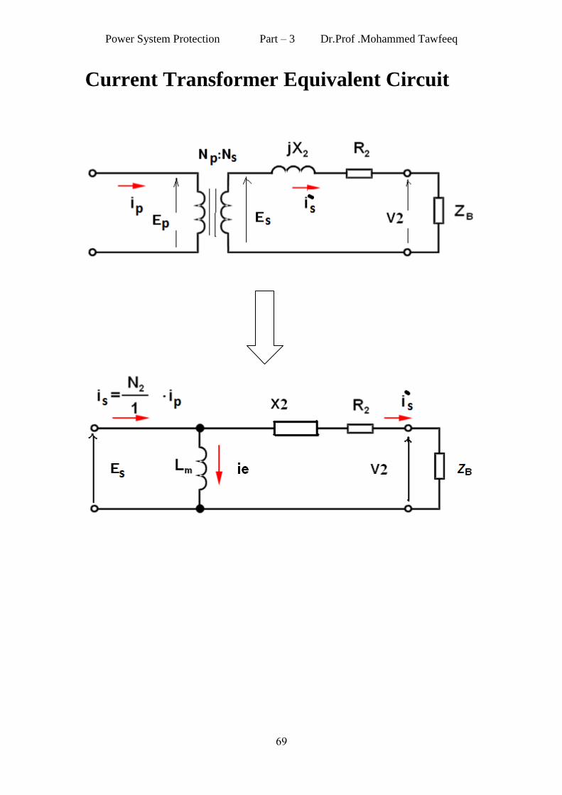
Current Transformer Equivalent Circuit

Power System Protection Part – 3 Dr.Prof .Mohammed Tawfeeq
67
CT Performance Calculations
The performance of a C.T may be found from two approaches :
1. The formula method.
2. The saturation curve method.
2- The saturation curve and error method.
The relation between Es and Ie is not linear like the relation shown in the Fig.1 due to the saturation of C.T core. Therefore the C.T. has ratio error.
Fig.1 Magnetizing curve

Power System Protection Part – 3 Dr.Prof .Mohammed Tawfeeq
67
The deviation of Is’ from Is is called the C.T error, and can be expressed as a percentage.
%100%100.'
xI
Ix
I
IITC
s
e
s
sserror
Where:
Is –Is’ = Ie
Is: Total current in the CT secondary Is’
: Current due to the CT load
Example:
Assume that a C.T has rated current ratio of 500/5 A. The impedance of
the secondary winding Z2 = 0.242 Ω, and the burden impedance ZB =
0.351 Ω .The core area A = 0.00193 m2. The C.T must operate at
máximum primary current of 10 kA.If the frequency is 60 Hz and the
core is built from silicon steel:
(a) Determine whether or not the C.T will saturate.
(b) Determine the C.T error.
Solution
Is= 10,000 x (5/500)= 100 A
If we neglect the excitation current Ie.
Is’ ≈ Is= 100 A.
Es = Is (ZB+Z2)
= 100 x (0.351 +0.242) = 59.29 V
Es = 4.44 * f * N2 * A * Bm
So:
T
xxx
15.1
001935.05
5006044.4
29.59Bm
As we know that the lower limit for the silcion steel saturation is
Bm = 1.2T Hence the C.T will not saturate.
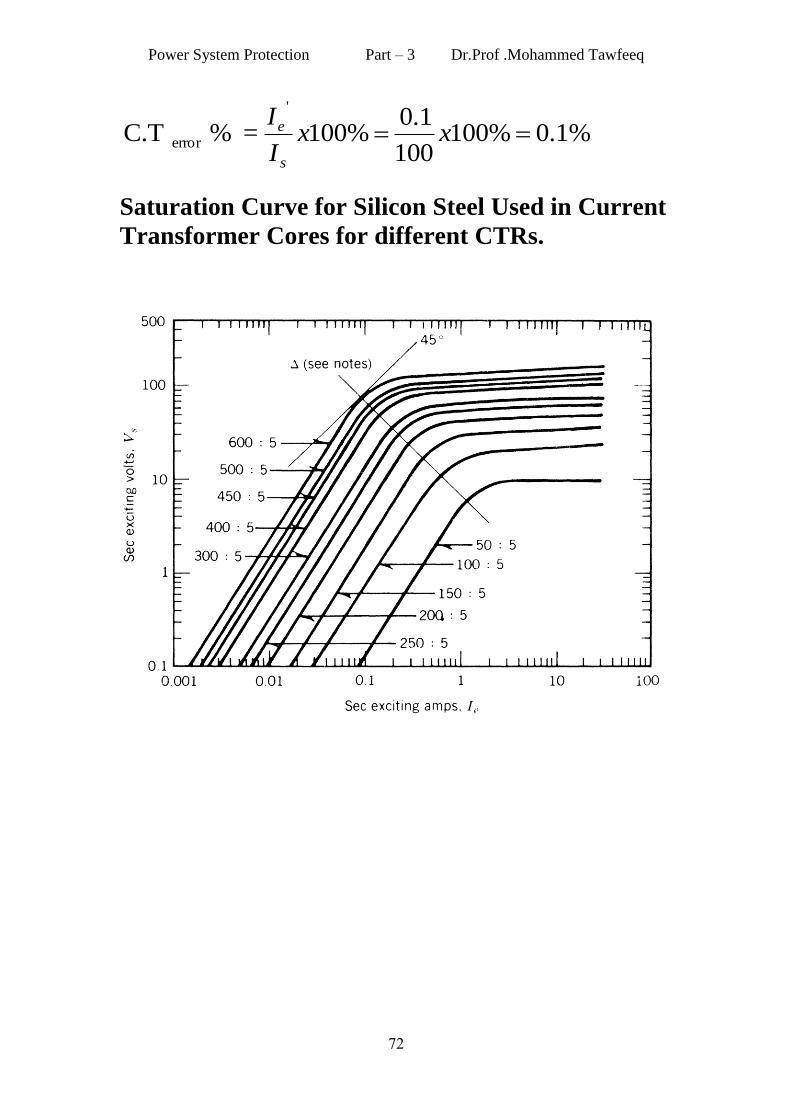
From the saturation curve the core corrsponding Ie for Es = 59.29 V
is Ie = 0.1 A.
Power System Protection Part – 3 Dr.Prof .Mohammed Tawfeeq
66
%1.0%100100
1.0%100= % C.T
'
error xxI
I
s
e
Saturation Curve for Silicon Steel Used in Current
Transformer Cores for different CTRs.
Power System Protection Part – 3 Dr.Prof .Mohammed Tawfeeq
66
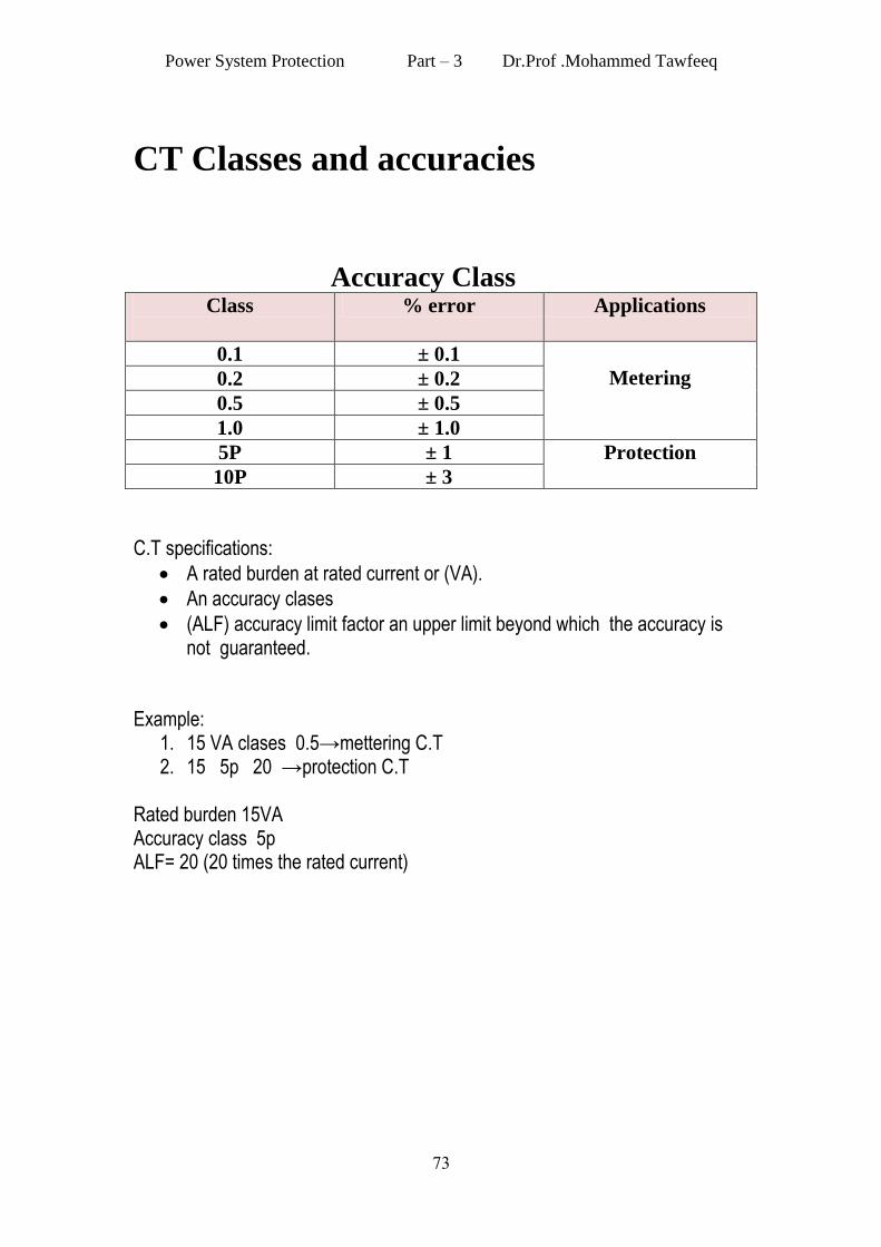
CT Classes and accuracies
Accuracy Class
Class
% error Applications
0.1 ± 0.1
Metering 0.2 ± 0.2
0.5 ± 0.5
1.0 ± 1.0
5P ± 1 Protection
10P ± 3
C.T specifications:
A rated burden at rated current or (VA).
An accuracy clases
(ALF) accuracy limit factor an upper limit beyond which the accuracy is not guaranteed.
Example: 1. 15 VA clases 0.5→mettering C.T 2. 15 5p 20 →protection C.T
Rated burden 15VA Accuracy class 5p ALF= 20 (20 times the rated current)
Power System Protection Part – 3 Dr.Prof .Mohammed Tawfeeq
66
Power System protection Dr. Mohamad Tawfeeq
Instrument Transformers
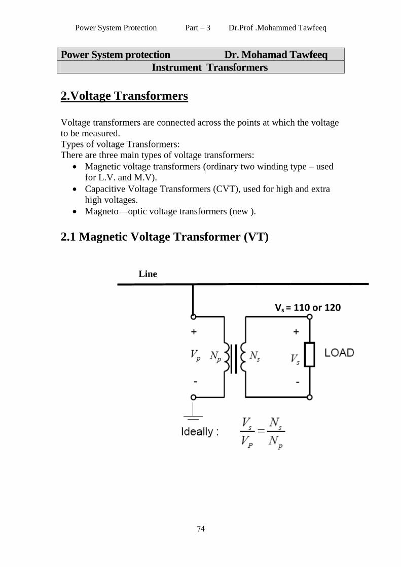
2.Voltage Transformers
Voltage transformers are connected across the points at which the voltage
to be measured.
Types of voltage Transformers:
There are three main types of voltage transformers:
Magnetic voltage transformers (ordinary two winding type – used
for L.V. and M.V).
Capacitive Voltage Transformers (CVT), used for high and extra
high voltages.
Magneto—optic voltage transformers (new ).
2.1 Magnetic Voltage Transformer (VT)
Line
Vs = 110 or 120
Power System Protection Part – 3 Dr.Prof .Mohammed Tawfeeq
66
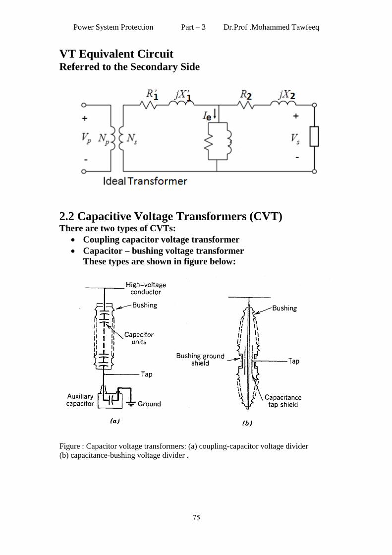
VT Equivalent Circuit Referred to the Secondary Side
2.2 Capacitive Voltage Transformers (CVT) There are two types of CVTs:
Coupling capacitor voltage transformer
Capacitor – bushing voltage transformer
These types are shown in figure below:
Figure : Capacitor voltage transformers: (a) coupling-capacitor voltage divider
(b) capacitance-bushing voltage divider .
Power System Protection Part – 3 Dr.Prof .Mohammed Tawfeeq
62
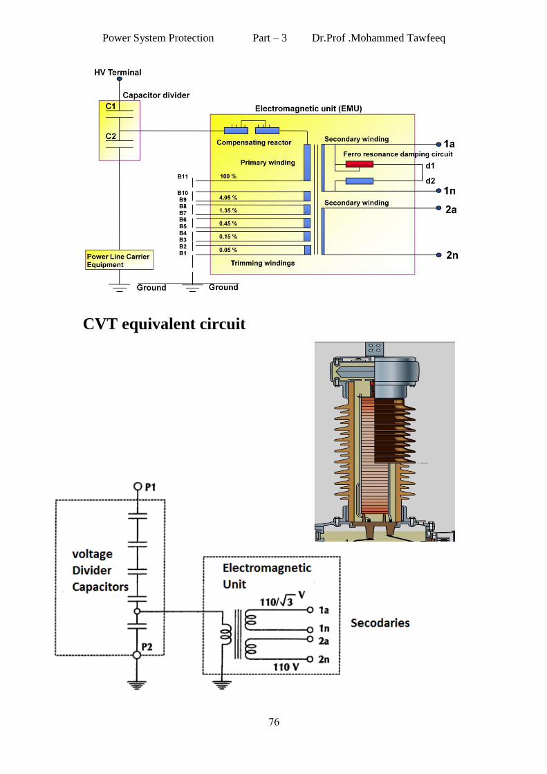
CVT equivalent circuit

Power System Protection Part – 3 Dr.Prof .Mohammed Tawfeeq
66
VT error : Errors in magnitude can be calculated
from :
Error VT= {(n Vs - Vp) / Vp} x 100%.
Table : Voltage transformers error limits Class Primary
voltage Voltage
error
(±%)
Phase error
(±min)
0.1 0.8 Vn , 1.0
Vn and 1.2
Vn
0.1 0.5
0.2 0.2 10.0
0.5 0.5 20.0
1.0 1.0 40.0
0.1
0.5 Vn
1.0 40.0
0.2 1.0 40.0
0.5 1.0 40.0
1.0 2.0 80.0
0.1
Vn
0.2 80.0
0.2 2.0 80.0
0.5 2.0 80.0
1.0 3.0 120.0
Vn =Nominal voltage

Power System Protection Part – 3 Dr.Prof .Mohammed Tawfeeq
66
VT connections
(b) delta – wye connection (a) Open delta connection
wye—wye connection (c)