
MEDIUM VOLTAGE INSTRUMENT TRANSFORMERS & SENSORS … · MEDIUM VOLTAGE INSTRUMENT TRANSFORMERS &...
137
— MEDIUM VOLTAGE INSTRUMENT TRANSFORMERS & SENSORS Instrument Transformer Reference Guide Metering and relaying applications for the electric power industry
Transcript of MEDIUM VOLTAGE INSTRUMENT TRANSFORMERS & SENSORS … · MEDIUM VOLTAGE INSTRUMENT TRANSFORMERS &...
—M ED I U M VO LTAG E I NS TRU M ENT TR A NS FO R M ER S & S ENSO R S
Instrument Transformer Reference GuideMetering and relaying applications for the electric power industry
3
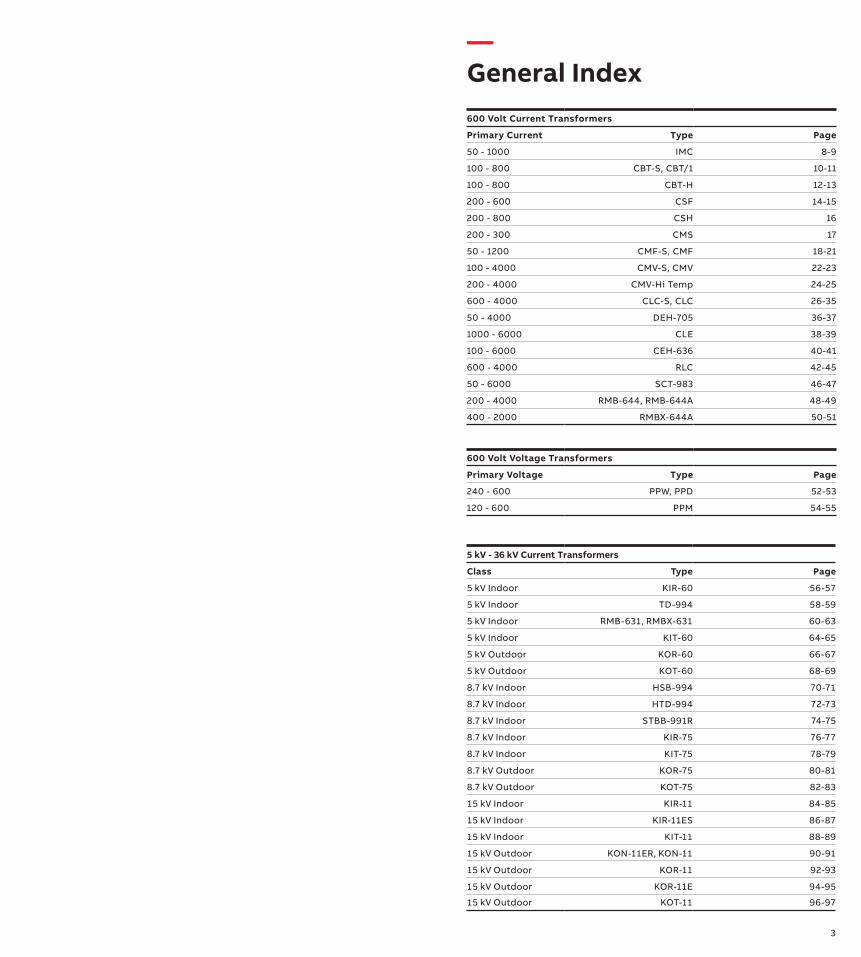
600 Volt Current Transformers
Primary Current Type Page
50 - 1000 IMC 8-9
100 - 800 CBT-S, CBT/1 10-11
100 - 800 CBT-H 12-13
200 - 600 CSF 14-15
200 - 800 CSH 16
200 - 300 CMS 17
50 - 1200 CMF-S, CMF 18-21
100 - 4000 CMV-S, CMV 22-23
200 - 4000 CMV-Hi Temp 24-25
600 - 4000 CLC-S, CLC 26-35
50 - 4000 DEH-705 36-37
1000 - 6000 CLE 38-39
100 - 6000 CEH-636 40-41
600 - 4000 RLC 42-45
50 - 6000 SCT-983 46-47
200 - 4000 RMB-644, RMB-644A 48-49
400 - 2000 RMBX-644A 50-51
600 Volt Voltage Transformers
Primary Voltage Type Page
240 - 600 PPW, PPD 52-53
120 - 600 PPM 54-55
5 kV - 36 kV Current Transformers
Class Type Page
5 kV Indoor KIR-60 56-57
5 kV Indoor TD-994 58-59
5 kV Indoor RMB-631, RMBX-631 60-63
5 kV Indoor KIT-60 64-65
5 kV Outdoor KOR-60 66-67
5 kV Outdoor KOT-60 68-69
8.7 kV Indoor HSB-994 70-71
8.7 kV Indoor HTD-994 72-73
8.7 kV Indoor STBB-991R 74-75
8.7 kV Indoor KIR-75 76-77
8.7 kV Indoor KIT-75 78-79
8.7 kV Outdoor KOR-75 80-81
8.7 kV Outdoor KOT-75 82-83
15 kV Indoor KIR-11 84-85
15 kV Indoor KIR-11ES 86-87
15 kV Indoor KIT-11 88-89
15 kV Outdoor KON-11ER, KON-11 90-91
15 kV Outdoor KOR-11 92-93
15 kV Outdoor KOR-11E 94-95
15 kV Outdoor KOT-11 96-97
—General Index
4 5
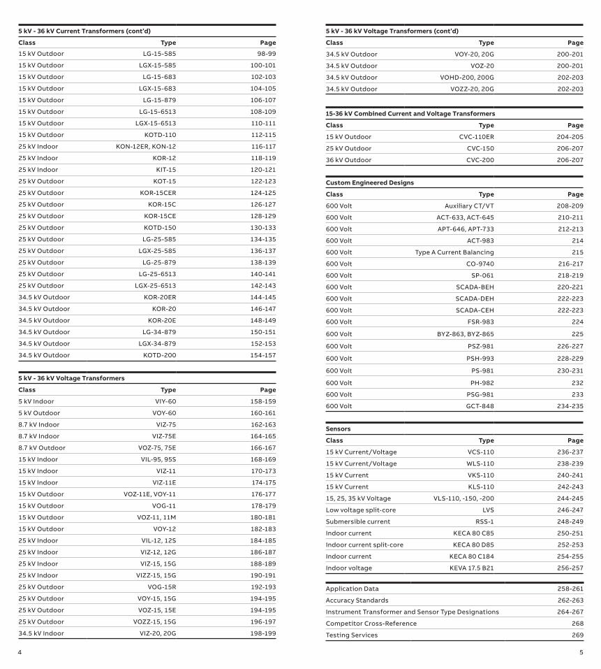
15-36 kV Combined Current and Voltage Transformers
Class Type Page
15 kV Outdoor CVC-110ER 204-205
25 kV Outdoor CVC-150 206-207
36 kV Outdoor CVC-200 206-207
5 kV - 36 kV Current Transformers (cont’d)
Class Type Page
15 kV Outdoor LG-15-585 98-99
15 kV Outdoor LGX-15-585 100-101
15 kV Outdoor LG-15-683 102-103
15 kV Outdoor LGX-15-683 104-105
15 kV Outdoor LG-15-879 106-107
15 kV Outdoor LG-15-6513 108-109
15 kV Outdoor LGX-15-6513 110-111
15 kV Outdoor KOTD-110 112-115
25 kV Indoor KON-12ER, KON-12 116-117
25 kV Indoor KOR-12 118-119
25 kV Indoor KIT-15 120-121
25 kV Outdoor KOT-15 122-123
25 kV Outdoor KOR-15CER 124-125
25 kV Outdoor KOR-15C 126-127
25 kV Outdoor KOR-15CE 128-129
25 kV Outdoor KOTD-150 130-133
25 kV Outdoor LG-25-585 134-135
25 kV Outdoor LGX-25-585 136-137
25 kV Outdoor LG-25-879 138-139
25 kV Outdoor LG-25-6513 140-141
25 kV Outdoor LGX-25-6513 142-143
34.5 kV Outdoor KOR-20ER 144-145
34.5 kV Outdoor KOR-20 146-147
34.5 kV Outdoor KOR-20E 148-149
34.5 kV Outdoor LG-34-879 150-151
34.5 kV Outdoor LGX-34-879 152-153
34.5 kV Outdoor KOTD-200 154-157
5 kV - 36 kV Voltage Transformers
Class Type Page
5 kV Indoor VIY-60 158-159
5 kV Outdoor VOY-60 160-161
8.7 kV Indoor VIZ-75 162-163
8.7 kV Indoor VIZ-75E 164-165
8.7 kV Outdoor VOZ-75, 75E 166-167
15 kV Indoor VIL-95, 95S 168-169
15 kV Indoor VIZ-11 170-173
15 kV Indoor VIZ-11E 174-175
15 kV Outdoor VOZ-11E, VOY-11 176-177
15 kV Outdoor VOG-11 178-179
15 kV Outdoor VOZ-11, 11M 180-181
15 kV Outdoor VOY-12 182-183
25 kV Indoor VIL-12, 12S 184-185
25 kV Indoor VIZ-12, 12G 186-187
25 kV Indoor VIZ-15, 15G 188-189
25 kV Indoor VIZZ-15, 15G 190-191
25 kV Outdoor VOG-15R 192-193
25 kV Outdoor VOY-15, 15G 194-195
25 kV Outdoor VOZ-15, 15E 194-195
25 kV Outdoor VOZZ-15, 15G 196-197
34.5 kV Indoor VIZ-20, 20G 198-199
Custom Engineered Designs
Class Type Page
600 Volt Auxiliary CT/VT 208-209
600 Volt ACT-633, ACT-645 210-211
600 Volt APT-646, APT-733 212-213
600 Volt ACT-983 214
600 Volt Type A Current Balancing 215
600 Volt CO-9740 216-217
600 Volt SP-061 218-219
600 Volt SCADA-BEH 220-221
600 Volt SCADA-DEH 222-223
600 Volt SCADA-CEH 222-223
600 Volt FSR-983 224
600 Volt BYZ-863, BYZ-865 225
600 Volt PSZ-981 226-227
600 Volt PSH-993 228-229
600 Volt PS-981 230-231
600 Volt PH-982 232
600 Volt PSG-981 233
600 Volt GCT-848 234-235
Application Data 258-261
Accuracy Standards 262-263
Instrument Transformer and Sensor Type Designations 264-267
Competitor Cross-Reference 268
Testing Services 269
Sensors
Class Type Page
15 kV Current/Voltage VCS-110 236-237
15 kV Current/Voltage WLS-110 238-239
15 kV Current VKS-110 240-241
15 kV Current KLS-110 242-243
15, 25, 35 kV Voltage VLS-110, -150, -200 244-245
Low voltage split-core LVS 246-247
Submersible current RSS-1 248-249
Indoor current KECA 80 C85 250-251
Indoor current split-core KECA 80 D85 252-253
Indoor current KECA 80 C184 254-255
Indoor voltage KEVA 17.5 B21 256-257
5 kV - 36 kV Voltage Transformers (cont’d)
Class Type Page
34.5 kV Outdoor VOY-20, 20G 200-201
34.5 kV Outdoor VOZ-20 200-201
34.5 kV Outdoor VOHD-200, 200G 202-203
34.5 kV Outdoor VOZZ-20, 20G 202-203

6 7
The styles listed in this guide represent those most commonly built for electric utilities, but are a small sample of what is offered. For more information or requests for special designs or units not listed in this guide, please contact your ABB representative.
VT Voltage DesignationsVoltage class designations may vary slightly by application. For ex-ample, units listed as 36 kV in this catalog may have a nominal sys-tem voltage rating of 34.5 kV and maximum system voltage rating of 36.5 kV, as per IEEE C57.13, and may be rated for 38 kV if used in switchgear applications.
14400/24940Y This unit is rated for 14400 operating volts. It can be connected at 14400 volts line-to-ground on a 24940 volt system (line-to-line volts are 24940 V) OR it can be connected line-to-line on a system with 14400 V line-to-line. This unit is not suitable for operation at 24940 volts. The “Y” indicates it has two fully insulated bushings, suitable for line-to-line connection.
14400/24940GY This unit is rated for 14400 operating volts. It can be connected at 14400 volts line-to-ground on a 24940 V system (line-to-line volts are 24940 V). It CANNOT be connected line-to-line. The “GY” indi-cates it only has one fully insulated bushing, making it suitable for line-to-ground connection only.
14400/14400Y This unit is rated for 14400 operating volts. It can be connected at 14400 V line-to-line.
14400/14400GY This unit is rated for 14400 operating volts; however, it can only be connected line-to-ground. Therefore, the actual operating voltage of the unit is 14400/1.73. The accuracy and thermal ratings of this unit are based on 14400 V. This is typical where there is a relay con-nected to the unit which should operate when there is a single line-to-ground fault. In this condition, the line-to-ground voltage be-comes equal to the line-to-line voltage. The “GY” indicates it only has one fully insulated bushing, making it suitable for line-to-ground connection only.
CT Rating Factor and VT Rated Voltage FactorThe rating factors (RF) and rated voltage factors (RVF) given in this catalog are listed per the IEEE standard. RF is based on 30°C ambi-ent temperature unless specified otherwise.
Transformers in this booklet conform to the following standards, where applicable:• IEEE Standard Requirements for Instrument Transformers,
C57.13–1993, C57.13-2008, or C57.13-2016, depending on the particular design
—I NS TRU M ENT TR A NS FO R M ER S A N D S ENSO R S
General information
• IEEE Standard for Instrument Transformers for Metering Purposes, C12.11 (current revision), where applicable.
• IEEE Standard for High Accuracy Instrument Transformers, C57.13.6–2005.
• Standards compliance with other standards may be available.
FrequenciesInstrument transformers are frequency-dependent devices. Metering and relaying accuracies for styles listed in this refer-ence guide are based on 60 Hz operation, unless otherwise noted. Products offered in this catalog may be designed for other frequencies such as 50 Hz.
AccuRange® current transformersABB’s AccuRange current transformers offer low and medium volt-age high accuracy, extended range transformers for revenue me-tering applications. AccuRange products are ONLY for metering applications and not for relaying applications. AccuRange 600 volt current transformers for secondary revenue metering deliver high accuracy and stable performance over a wide load range. Accuracy is guaranteed to exceed the IEEE 0.15S accuracy class and obtain 0.15% accuracy from 1% of nominal current through rating factor.
Medium voltage outdoor insulation materialOutdoor medium voltage instrument transformers and sensors are encapsulated in polyurethane or hydrophobic cycloaliphatic epoxy (HCEP). HCEP is preferred for longer service life in most out-door applications due to its superior arc track, ozone, and ultravi-olet-resistive properties. The hydrophobic surface properties of HCEP also provide excellent performance in wet, humid, or pol-luted environments.
Sensors are vacuum cast in HCEP, while instrument transformers are cast using the automatic pressure gelation (APG) process. APG shortens manufacturing cycle times and ensures product consis-tency, quality, and reliability in outdoor performance.
Medium voltage sensors Electronic instrument transformers (sensors) offer an alternative way of making the current and voltage measurements. Sensors based on alternative principles have been introduced as succes-sors to conventional instrument transformers in order to signifi-cantly reduce size, increase safety, and to provide greater rating standardization and a wider functionality range. These well known principles can only be fully utilized in combination with versatile electronic relays.
ABB ResiVolt™ technologyUnits with ABB ResiVolt technology are designed to withstand challenging environments where very fast transient (VFT) over-voltages are present. Ever changing grid configurations and focus on reliability, efficiency, sustainability, and capacity has led to a significant increase of reclosers, switching devices, and ca-pacitors that can introduce VFT events.
8 9
Primary Amps
Style Number B-0.1
B-0.2 B-0.5
Window Diam. (in.)
30°C
55°C
Height (in.)
Width (in.)
Length (in.)
Weight (lbs.)
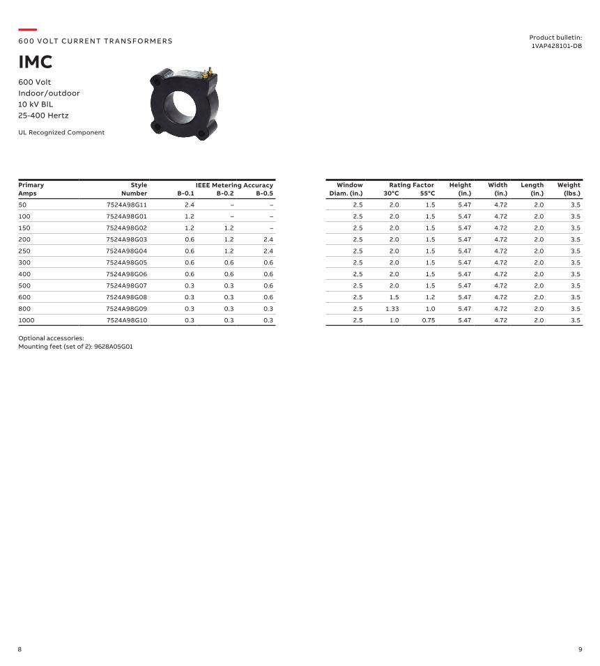
50 7524A98G11 2.4 – – 2.5 2.0 1.5 5.47 4.72 2.0 3.5
100 7524A98G01 1.2 – – 2.5 2.0 1.5 5.47 4.72 2.0 3.5
150 7524A98G02 1.2 1.2 – 2.5 2.0 1.5 5.47 4.72 2.0 3.5
200 7524A98G03 0.6 1.2 2.4 2.5 2.0 1.5 5.47 4.72 2.0 3.5
250 7524A98G04 0.6 1.2 2.4 2.5 2.0 1.5 5.47 4.72 2.0 3.5
300 7524A98G05 0.6 0.6 0.6 2.5 2.0 1.5 5.47 4.72 2.0 3.5
400 7524A98G06 0.6 0.6 0.6 2.5 2.0 1.5 5.47 4.72 2.0 3.5
500 7524A98G07 0.3 0.3 0.6 2.5 2.0 1.5 5.47 4.72 2.0 3.5
600 7524A98G08 0.3 0.3 0.6 2.5 1.5 1.2 5.47 4.72 2.0 3.5
800 7524A98G09 0.3 0.3 0.3 2.5 1.33 1.0 5.47 4.72 2.0 3.5
1000 7524A98G10 0.3 0.3 0.3 2.5 1.0 0.75 5.47 4.72 2.0 3.5
Rating Factor
—6 0 0 VO LT CU R R ENT TR A NS FO R M ER S
IMC600 Volt Indoor/outdoor 10 kV BIL25-400 Hertz
IEEE Metering Accuracy
Optional accessories:Mounting feet (set of 2): 9628A05G01
Product bulletin:1VAP428101-DB
UL Recognized Component
10 11
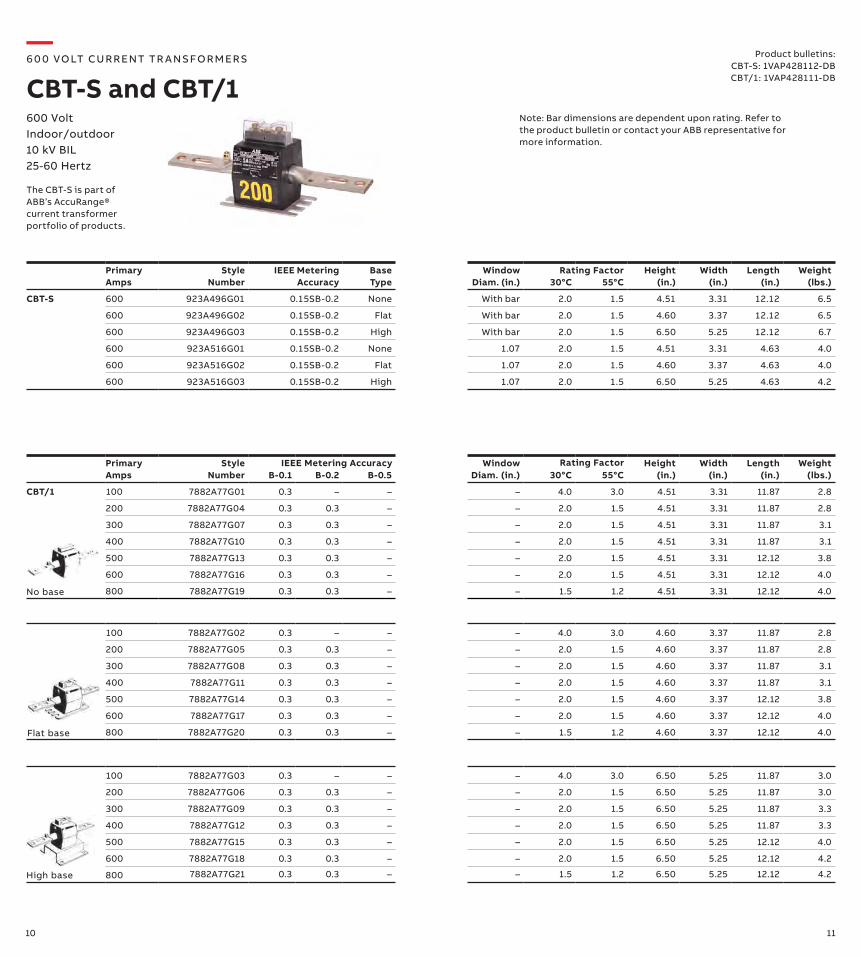
Product bulletins:CBT-S: 1VAP428112-DBCBT/1: 1VAP428111-DB
Primary Amps
Style Number B-0.1
B-0.2 B-0.5
Window Diam. (in.)
30°C
55°C
Height (in.)
Width (in.)
Length (in.)
Weight (lbs.)
CBT/1 100 7882A77G01 0.3 – – – 4.0 3.0 4.51 3.31 11.87 2.8
200 7882A77G04 0.3 0.3 – – 2.0 1.5 4.51 3.31 11.87 2.8
300 7882A77G07 0.3 0.3 – – 2.0 1.5 4.51 3.31 11.87 3.1
400 7882A77G10 0.3 0.3 – – 2.0 1.5 4.51 3.31 11.87 3.1
500 7882A77G13 0.3 0.3 – – 2.0 1.5 4.51 3.31 12.12 3.8
600 7882A77G16 0.3 0.3 – – 2.0 1.5 4.51 3.31 12.12 4.0
800 7882A77G19 0.3 0.3 – – 1.5 1.2 4.51 3.31 12.12 4.0
100 7882A77G02 0.3 – – – 4.0 3.0 4.60 3.37 11.87 2.8
200 7882A77G05 0.3 0.3 – – 2.0 1.5 4.60 3.37 11.87 2.8
300 7882A77G08 0.3 0.3 – – 2.0 1.5 4.60 3.37 11.87 3.1
400 7882A77G11 0.3 0.3 – – 2.0 1.5 4.60 3.37 11.87 3.1
500 7882A77G14 0.3 0.3 – – 2.0 1.5 4.60 3.37 12.12 3.8
600 7882A77G17 0.3 0.3 – – 2.0 1.5 4.60 3.37 12.12 4.0
800 7882A77G20 0.3 0.3 – – 1.5 1.2 4.60 3.37 12.12 4.0
100 7882A77G03 0.3 – – – 4.0 3.0 6.50 5.25 11.87 3.0
200 7882A77G06 0.3 0.3 – – 2.0 1.5 6.50 5.25 11.87 3.0
300 7882A77G09 0.3 0.3 – – 2.0 1.5 6.50 5.25 11.87 3.3
400 7882A77G12 0.3 0.3 – – 2.0 1.5 6.50 5.25 11.87 3.3
500 7882A77G15 0.3 0.3 – – 2.0 1.5 6.50 5.25 12.12 4.0
600 7882A77G18 0.3 0.3 – – 2.0 1.5 6.50 5.25 12.12 4.2
800 7882A77G21 0.3 0.3 – – 1.5 1.2 6.50 5.25 12.12 4.2
No base
Flat base
High base
Primary Amps
Style Number
IEEE Metering Accuracy
Base Type
Window Diam. (in.) 30°C
55°C
Height (in.)
Width (in.)
Length (in.)
Weight (lbs.)
CBT-S 600 923A496G01 0.15SB-0.2 None With bar 2.0 1.5 4.51 3.31 12.12 6.5
600 923A496G02 0.15SB-0.2 Flat With bar 2.0 1.5 4.60 3.37 12.12 6.5
600 923A496G03 0.15SB-0.2 High With bar 2.0 1.5 6.50 5.25 12.12 6.7
600 923A516G01 0.15SB-0.2 None 1.07 2.0 1.5 4.51 3.31 4.63 4.0
600 923A516G02 0.15SB-0.2 Flat 1.07 2.0 1.5 4.60 3.37 4.63 4.0
600 923A516G03 0.15SB-0.2 High 1.07 2.0 1.5 6.50 5.25 4.63 4.2
Rating Factor
IEEE Metering Accuracy Rating Factor
—6 0 0 VO LT CU R R ENT TR A NS FO R M ER S
CBT-S and CBT/1600 VoltIndoor/outdoor 10 kV BIL25-60 Hertz
The CBT-S is part of ABB’s AccuRange® current transformer portfolio of products.
Note: Bar dimensions are dependent upon rating. Refer to the product bulletin or contact your ABB representative for more information.
12 13
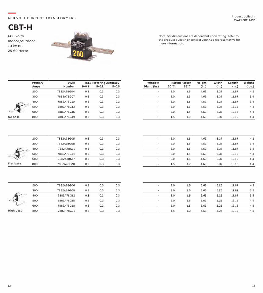
200 7882A78G05 0.3 0.3 0.3 - 2.0 1.5 4.62 3.37 11.87 4.2
300 7882A78G08 0.3 0.3 0.3 - 2.0 1.5 4.62 3.37 11.87 3.4
400 7882A78G11 0.3 0.3 0.3 - 2.0 1.5 4.62 3.37 11.87 3.4
500 7882A78G14 0.3 0.3 0.3 - 2.0 1.5 4.62 3.37 12.12 4.3
600 7882A78G17 0.3 0.3 0.3 - 2.0 1.5 4.62 3.37 12.12 4.4
800 7882A78G20 0.3 0.3 0.3 - 1.5 1.2 4.62 3.37 12.12 4.4
Primary Amps
Style Number B-0.1
B-0.2 B-0.5
Window Diam. (in.)
30°C
55°C
Height (in.)
Width (in.)
Length (in.)
Weight (lbs.)
200 7882A78G04 0.3 0.3 0.3 - 2.0 1.5 4.62 3.37 11.87 4.2
300 7882A78G07 0.3 0.3 0.3 - 2.0 1.5 4.62 3.37 11.87 3.4
400 7882A78G10 0.3 0.3 0.3 - 2.0 1.5 4.62 3.37 11.87 3.4
500 7882A78G13 0.3 0.3 0.3 - 2.0 1.5 4.62 3.37 12.12 4.3
600 7882A78G16 0.3 0.3 0.3 - 2.0 1.5 4.62 3.37 12.12 4.4
800 7882A78G19 0.3 0.3 0.3 - 1.5 1.2 4.62 3.37 12.12 4.4
Rating Factor
Product bulletin:1VAP428111-DB
200 7882A78G06 0.3 0.3 0.3 - 2.0 1.5 6.63 5.25 11.87 4.3
300 7882A78G09 0.3 0.3 0.3 - 2.0 1.5 6.63 5.25 11.87 3.5
400 7882A78G12 0.3 0.3 0.3 - 2.0 1.5 6.63 5.25 11.87 3.5
500 7882A78G15 0.3 0.3 0.3 - 2.0 1.5 6.63 5.25 12.12 4.4
600 7882A78G18 0.3 0.3 0.3 - 2.0 1.5 6.63 5.25 12.12 4.5
800 7882A78G21 0.3 0.3 0.3 - 1.5 1.2 6.63 5.25 12.12 4.5
Flat base
High base
No base
IEEE Metering Accuracy
—6 0 0 VO LT CU R R ENT TR A NS FO R M ER S
CBT-H600 volts Indoor/outdoor 10 kV BIL25-60 Hertz
Note: Bar dimensions are dependent upon rating. Refer to the product bulletin or contact your ABB representative for more information.
14 15
Primary Amps
Style Number B-0.1
B-0.2 B-0.5
Window Diam. (in.)
30°C
55°C
Height (in.)
Width (in.)
Length (in.)
Weight (lbs.)
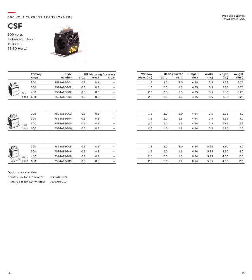
200 7524A85G01 0.3 0.3 – 1.5 3.0 2.0 4.85 3.5 3.32 3.75
300 7524A85G02 0.3 0.3 – 1.5 2.0 1.5 4.85 3.5 3.32 3.75
400 7524A83G02 0.3 0.3 – 2.0 2.0 1.5 4.85 3.5 3.32 2.25
600 7524A83G03 0.3 0.3 – 2.0 1.5 1.2 4.85 3.5 3.32 2.25
200 7524A85G03 0.3 0.3 – 1.5 3.0 2.0 4.94 3.5 5.25 4.0
300 7524A85G04 0.3 0.3 – 1.5 2.0 1.5 4.94 3.5 5.25 4.0
400 7524A83G05 0.3 0.3 – 2.0 2.0 1.5 4.94 3.5 5.25 2.5
600 7524A83G06 0.3 0.3 – 2.0 1.5 1.2 4.94 3.5 5.25 2.5
200 7524A85G05 0.3 0.3 – 1.5 3.0 2.0 6.54 5.25 4.50 4.0
300 7524A85G06 0.3 0.3 – 1.5 2.0 1.5 6.54 5.25 4.50 4.0
400 7524A83G08 0.3 0.3 – 2.0 2.0 1.5 6.54 5.25 4.50 2.5
600 7524A83G09 0.3 0.3 – 2.0 1.5 1.2 6.54 5.25 4.50 2.5
Rating Factor
Optional accessories:
Primary bar for 1.5" window 9628A05G09
Primary bar for 2.0" window 9628A05G10
IEEE Metering Accuracy
No base
Flatbase
High base
—6 0 0 VO LT CU R R ENT TR A NS FO R M ER S
CSF600 volts Indoor/outdoor 10 kV BIL25-60 Hertz
Product bulletin:1VAP428131-DB
16 17
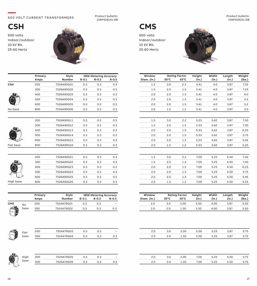
200 7526A90G11 0.3 0.3 0.3 1.5 3.0 2.2 5.53 5.62 3.87 7.50
300 7526A90G12 0.3 0.3 0.3 1.5 2.0 1.5 5.53 5.62 3.87 7.50
400 7526A90G13 0.3 0.3 0.3 2.0 2.0 1.5 5.53 5.62 3.87 6.25
500 7526A90G14 0.3 0.3 0.3 2.0 2.0 1.5 5.53 5.62 3.87 5.75
600 7526A90G15 0.3 0.3 0.3 2.0 2.0 1.5 5.53 5.62 3.87 5.45
800 7526A90G16 0.3 0.3 0.3 2.0 1.5 1.2 5.53 5.62 3.87 5.25
Primary Amps
Style Number B-0.1
B-0.2 B-0.5
Window Diam. (in.)
30°C
55°C
Height (in.)
Width (in.)
Length (in.)
Weight (lbs.)
CSH 200 7526A90G01 0.3 0.3 0.3 1.5 3.0 2.2 5.41 4.0 3.87 7.25
300 7526A90G02 0.3 0.3 0.3 1.5 2.0 1.5 5.41 4.0 3.87 7.25
400 7526A90G03 0.3 0.3 0.3 2.0 2.0 1.5 5.41 4.0 3.87 6.0
500 7526A90G04 0.3 0.3 0.3 2.0 2.0 1.5 5.41 4.0 3.87 5.5
600 7526A90G05 0.3 0.3 0.3 2.0 2.0 1.5 5.41 4.0 3.87 5.2
800 7526A90G06 0.3 0.3 0.3 2.0 1.5 1.2 5.41 4.0 3.87 5.0
Rating Factor
200 7526A90G21 0.3 0.3 0.3 1.5 3.0 2.2 7.09 5.25 4.50 7.50
300 7526A90G22 0.3 0.3 0.3 1.5 2.0 1.5 7.09 5.25 4.50 7.50
400 7526A90G23 0.3 0.3 0.3 2.0 2.0 1.5 7.09 5.25 4.50 6.25
500 7526A90G24 0.3 0.3 0.3 2.0 2.0 1.5 7.09 5.25 4.50 5.75
600 7526A90G25 0.3 0.3 0.3 2.0 2.0 1.5 7.09 5.25 4.50 5.45
800 7526A90G26 0.3 0.3 0.3 2.0 1.5 1.2 7.09 5.25 4.50 5.25
200 7524A79G03 0.3 0.3 – 2.0 3.0 2.00 5.59 5.25 3.87 5.75
300 7524A79G04 0.3 0.3 0.3 2.0 2.0 1.50 5.59 5.25 3.87 5.75
200 7524A79G05 0.3 0.3 – 2.0 3.0 2.00 7.09 5.25 4.50 5.75
300 7524A79G06 0.3 0.3 0.3 2.0 2.0 1.50 7.09 5.25 4.50 5.75
Primary Amps
Style Number B-0.1
B-0.2 B-0.5
Window Diam. (in.)
30°C
55°C
Height (in.)
Width (in.)
Length (in.)
Weight (lbs.)
CMS 200 7524A79G01 0.3 0.3 – 2.0 3.0 2.00 5.50 4.00 3.87 5.50
300 7524A79G02 0.3 0.3 0.3 2.0 2.0 1.50 5.50 4.00 3.87 5.50
IEEE Metering Accuracy
High base
No base
No base
Flat base
High base
—6 0 0 VO LT CU R R ENT TR A NS FO R M ER S
CSH600 volts Indoor/outdoor 10 kV BIL25-60 Hertz
Flat base
Product bulletin:1VAP428151-DB
Product bulletin:1VAP428141-DB
600 volts Indoor/outdoor 10 kV BIL25-60 Hertz
Rating FactorIEEE Metering Accuracy
CMS
18 19
Primary Amps
Style Number B-0.1
B-0.2 B-0.5 B-1.8
Window Diam. (in.)
30°C
55°C
Height (in.)
Width (in.)
Length (in.)
Weight (lbs.)
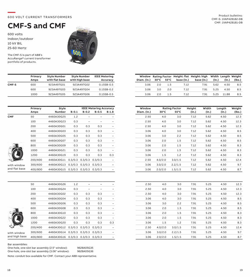
CMF 50 4460A30G25 1.2 – – – 2.50 4.0 3.0 7.12 5.62 4.50 12.3
100 4460A30G23 0.3 – – – 2.50 4.0 3.0 7.12 5.62 4.50 12.3
200 4460A30G01 0.3 0.3 0.3 – 2.50 4.0 3.0 7.12 5.62 4.50 12.3
400 4460A30G03 0.3 0.3 0.3 – 3.06 4.0 3.0 7.12 5.62 4.50 8.5
500 4460A30G05 0.3 0.3 0.3 – 3.06 3.0 2.2 7.12 5.62 4.50 8.5
600 4460A30G07 0.3 0.3 0.3 – 3.06 2.0 1.5 7.12 5.62 4.50 8.5
800 4460A30G09 0.3 0.3 0.3 – 3.06 2.0 1.5 7.12 5.62 4.50 8.3
1000 4460A30G21 0.3 0.3 0.3 – 3.06 2.0 1.5 7.12 5.62 4.50 8.3
1200 4460A30G19 0.3 0.3 0.3 0.3 3.06 1.5 1.2 7.12 5.62 4.50 8.3
200/400 4460A30G11 0.3/0.3 0.3/0.3 0.3/0.3 – 2.50 4.0/2.0 3.0/1.5 7.12 5.62 4.50 12.4
300/600 4460A30G13 0.3/0.3 0.3/0.3 0.3/0.3 – 3.06 3.0/2.0 2.2/1.5 7.12 5.62 4.50 9.7
400/800 4460A30G15 0.3/0.3 0.3/0.3 0.3/0.3 – 3.06 2.0/2.0 1.5/1.5 7.12 5.62 4.50 8.7
IEEE Metering Accuracy
with window and flat base
with window and high base
Primary Amps
Style Number with flat base
Style Number with high base
IEEE Metering Accuracy
Window Diam. (in.)
30°C
55°C
Height: flat base (in.)
Height: high base (in.)
Width (in.)
Length (in.)
Weight (lbs.)
CMF-S 600 923A497G01 923A497G02 0.15SB-0.5 3.06 2.0 1.5 7.12 7.91 5.62 4.50 8.5
600 923A497G03 923A497G04 0.15SB-0.2 3.06 3.0 2.0 7.12 7.91 5.25 4.50 8.5
1000 923A497G05 923A497G06 0.15SB-0.5 3.06 2.0 1.5 7.12 7.91 5.25 11.88 8.5
Rating Factor
Bar assemblies:One-hole, one-slot bar assembly (2.5" window): 9628A05G35One-hole, one-slot bar assembly (3.06" window): 9628A05G36
Note: conduit box available for CMF. Contact your ABB representative.
Product bulletins:CMF-S: 1VAP428182-DB
CMF: 1VAP428181-DB
600 volts Indoor/outdoor 10 kV BIL25-60 Hertz
—6 0 0 VO LT CU R R ENT TR A NS FO R M ER S
CMF-S and CMF
Rating Factor
50 4460A30G26 1.2 – – – 2.50 4.0 3.0 7.91 5.25 4.50 12.3
100 4460A30G24 0.3 – – – 2.50 4.0 3.0 7.91 5.25 4.50 12.3
200 4460A30G02 0.3 0.3 0.3 – 2.50 4.0 3.0 7.91 5.25 4.50 12.3
400 4460A30G04 0.3 0.3 0.3 – 3.06 4.0 3.0 7.91 5.25 4.50 8.5
500 4460A30G06 0.3 0.3 0.3 – 3.06 3.0 2.2 7.91 5.25 4.50 8.5
600 4460A30G08 0.3 0.3 0.3 – 3.06 2.0 1.5 7.91 5.25 4.50 8.5
800 4460A30G10 0.3 0.3 0.3 – 3.06 2.0 1.5 7.91 5.25 4.50 8.3
1000 4460A30G22 0.3 0.3 0.3 – 3.06 2.0 1.5 7.91 5.25 4.50 8.3
1200 4460A30G20 0.3 0.3 0.3 0.3 3.06 1.5 1.2 7.91 5.25 4.50 8.3
200/400 4460A30G12 0.3/0.3 0.3/0.3 0.3/0.3 – 2.50 4.0/2.0 3.0/1.5 7.91 5.25 4.50 12.4
300/600 4460A30G14 0.3/0.3 0.3/0.3 0.3/0.3 – 3.06 3.0/2.0 2.2/1.5 7.91 5.25 4.50 9.7
400/800 4460A30G16 0.3/0.3 0.3/0.3 0.3/0.3 – 3.06 2.0/2.0 1.5/1.5 7.91 5.25 4.50 8.7
The CMF-S is part of ABB’s AccuRange® current transformer portfolio of products.
20 21
100 7525A01G26 0.3 – – – 2.50 4.0 3.0 7.91 5.25 11.88 14.3
200 7525A01G02 0.3 0.3 0.3 – 2.50 4.0 3.0 7.91 5.25 11.88 14.3
400 7525A01G04 0.3 0.3 0.3 – 3.06 4.0 3.0 7.91 5.25 11.88 12.5
500 7525A01G06 0.3 0.3 0.3 – 3.06 3.0 2.2 7.91 5.25 11.88 12.5
600 7525A01G08 0.3 0.3 0.3 – 3.06 2.0 1.5 7.91 5.25 11.88 12.5
800 7525A01G10 0.3 0.3 0.3 – 3.06 2.0 1.5 7.91 5.25 11.88 12.3
1000 7525A01G24 0.3 0.3 0.3 – 3.06 2.0 1.5 7.91 5.25 11.88 12.3
1200 7525A01G20 0.3 0.3 0.3 0.3 3.06 1.5 1.2 7.91 5.25 11.88 12.3
200/400 7525A01G12 0.3/0.3 0.3/0.3 0.3/0.3 – 2.50 4.0/2.0 3.0/1.5 7.91 5.25 11.88 14.4
300/600 7525A01G14 0.3/0.3 0.3/0.3 0.3/0.3 – 3.06 3.0/2.0 2.2/1.5 7.91 5.25 11.88 13.7
400/800 7525A01G16 0.3/0.3 0.3/0.3 0.3/0.3 – 3.06 2.0/2.0 1.5/1.5 7.91 5.25 11.88 12.7
Primary Amps
Style Number B-0.1
B-0.2 B-0.5 B-1.8
Window Diam. (in.)
30°C
55°C
Height (in.)
Width (in.)
Length (in.)
Weight (lbs.)
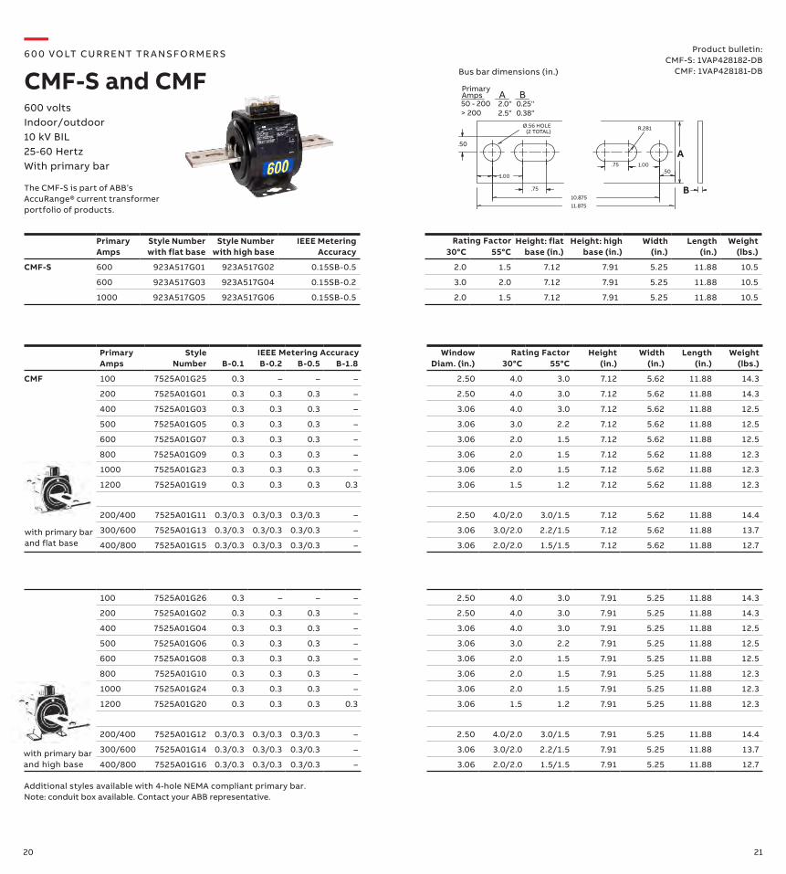
CMF 100 7525A01G25 0.3 – – – 2.50 4.0 3.0 7.12 5.62 11.88 14.3
200 7525A01G01 0.3 0.3 0.3 – 2.50 4.0 3.0 7.12 5.62 11.88 14.3
400 7525A01G03 0.3 0.3 0.3 – 3.06 4.0 3.0 7.12 5.62 11.88 12.5
500 7525A01G05 0.3 0.3 0.3 – 3.06 3.0 2.2 7.12 5.62 11.88 12.5
600 7525A01G07 0.3 0.3 0.3 – 3.06 2.0 1.5 7.12 5.62 11.88 12.5
800 7525A01G09 0.3 0.3 0.3 – 3.06 2.0 1.5 7.12 5.62 11.88 12.3
1000 7525A01G23 0.3 0.3 0.3 – 3.06 2.0 1.5 7.12 5.62 11.88 12.3
1200 7525A01G19 0.3 0.3 0.3 0.3 3.06 1.5 1.2 7.12 5.62 11.88 12.3
200/400 7525A01G11 0.3/0.3 0.3/0.3 0.3/0.3 – 2.50 4.0/2.0 3.0/1.5 7.12 5.62 11.88 14.4
300/600 7525A01G13 0.3/0.3 0.3/0.3 0.3/0.3 – 3.06 3.0/2.0 2.2/1.5 7.12 5.62 11.88 13.7
400/800 7525A01G15 0.3/0.3 0.3/0.3 0.3/0.3 – 3.06 2.0/2.0 1.5/1.5 7.12 5.62 11.88 12.7
Rating Factor
Product bulletin:CMF-S: 1VAP428182-DB
CMF: 1VAP428181-DB
1.00
.75
.501.00.75
Ø.56 HOLE(2 TOTAL) R.281
10.87511.875
.50
PrimaryAmps A
A
B
B0.25"0.38"
2.0"2.5"
50 - 200> 200
Bus bar dimensions (in.)
IEEE Metering Accuracy
with primary bar and high base
with primary bar and flat base
Additional styles available with 4-hole NEMA compliant primary bar.Note: conduit box available. Contact your ABB representative.
600 volts Indoor/outdoor 10 kV BIL25-60 HertzWith primary bar
—6 0 0 VO LT CU R R ENT TR A NS FO R M ER S
CMF-S and CMF
Primary Amps
Style Number with flat base
Style Number with high base
IEEE Metering Accuracy
30°C
55°C
Height: flat base (in.)
Height: high base (in.)
Width (in.)
Length (in.)
Weight (lbs.)
CMF-S 600 923A517G01 923A517G02 0.15SB-0.5 2.0 1.5 7.12 7.91 5.25 11.88 10.5
600 923A517G03 923A517G04 0.15SB-0.2 3.0 2.0 7.12 7.91 5.25 11.88 10.5
1000 923A517G05 923A517G06 0.15SB-0.5 2.0 1.5 7.12 7.91 5.25 11.88 10.5
The CMF-S is part of ABB’s AccuRange® current transformer portfolio of products.
Rating Factor
22 23
Primary Amps
Style Number B-0.1
B-0.2 B-0.5 B-0.9
B-1.8
Window Diam. (in.) 30°C
55°C
Height (in.)
Width (in.)
Length (in.)
Weight (lbs.)
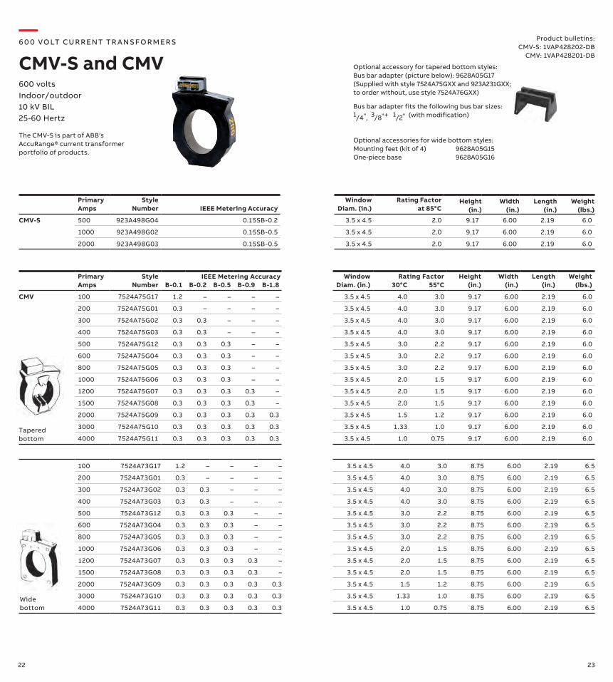
CMV 100 7524A75G17 1.2 – – – – 3.5 x 4.5 4.0 3.0 9.17 6.00 2.19 6.0
200 7524A75G01 0.3 – – – – 3.5 x 4.5 4.0 3.0 9.17 6.00 2.19 6.0
300 7524A75G02 0.3 0.3 – – – 3.5 x 4.5 4.0 3.0 9.17 6.00 2.19 6.0
400 7524A75G03 0.3 0.3 – – – 3.5 x 4.5 4.0 3.0 9.17 6.00 2.19 6.0
500 7524A75G12 0.3 0.3 0.3 – – 3.5 x 4.5 3.0 2.2 9.17 6.00 2.19 6.0
600 7524A75G04 0.3 0.3 0.3 – – 3.5 x 4.5 3.0 2.2 9.17 6.00 2.19 6.0
800 7524A75G05 0.3 0.3 0.3 – – 3.5 x 4.5 3.0 2.2 9.17 6.00 2.19 6.0
1000 7524A75G06 0.3 0.3 0.3 – – 3.5 x 4.5 2.0 1.5 9.17 6.00 2.19 6.0
1200 7524A75G07 0.3 0.3 0.3 0.3 – 3.5 x 4.5 2.0 1.5 9.17 6.00 2.19 6.0
1500 7524A75G08 0.3 0.3 0.3 0.3 – 3.5 x 4.5 2.0 1.5 9.17 6.00 2.19 6.0
2000 7524A75G09 0.3 0.3 0.3 0.3 0.3 3.5 x 4.5 1.5 1.2 9.17 6.00 2.19 6.0
3000 7524A75G10 0.3 0.3 0.3 0.3 0.3 3.5 x 4.5 1.33 1.0 9.17 6.00 2.19 6.0
4000 7524A75G11 0.3 0.3 0.3 0.3 0.3 3.5 x 4.5 1.0 0.75 9.17 6.00 2.19 6.0
100 7524A73G17 1.2 – – – – 3.5 x 4.5 4.0 3.0 8.75 6.00 2.19 6.5
200 7524A73G01 0.3 – – – – 3.5 x 4.5 4.0 3.0 8.75 6.00 2.19 6.5
300 7524A73G02 0.3 0.3 – – – 3.5 x 4.5 4.0 3.0 8.75 6.00 2.19 6.5
400 7524A73G03 0.3 0.3 – – – 3.5 x 4.5 4.0 3.0 8.75 6.00 2.19 6.5
500 7524A73G12 0.3 0.3 0.3 – – 3.5 x 4.5 3.0 2.2 8.75 6.00 2.19 6.5
600 7524A73G04 0.3 0.3 0.3 – – 3.5 x 4.5 3.0 2.2 8.75 6.00 2.19 6.5
800 7524A73G05 0.3 0.3 0.3 – – 3.5 x 4.5 3.0 2.2 8.75 6.00 2.19 6.5
1000 7524A73G06 0.3 0.3 0.3 – – 3.5 x 4.5 2.0 1.5 8.75 6.00 2.19 6.5
1200 7524A73G07 0.3 0.3 0.3 0.3 – 3.5 x 4.5 2.0 1.5 8.75 6.00 2.19 6.5
1500 7524A73G08 0.3 0.3 0.3 0.3 – 3.5 x 4.5 2.0 1.5 8.75 6.00 2.19 6.5
2000 7524A73G09 0.3 0.3 0.3 0.3 0.3 3.5 x 4.5 1.5 1.2 8.75 6.00 2.19 6.5
3000 7524A73G10 0.3 0.3 0.3 0.3 0.3 3.5 x 4.5 1.33 1.0 8.75 6.00 2.19 6.5
4000 7524A73G11 0.3 0.3 0.3 0.3 0.3 3.5 x 4.5 1.0 0.75 8.75 6.00 2.19 6.5
Product bulletins:CMV-S: 1VAP428202-DB
CMV: 1VAP428201-DB
Optional accessory for tapered bottom styles:Bus bar adapter (picture below): 9628A05G17 (Supplied with style 7524A75GXX and 923A231GXX; to order without, use style 7524A76GXX)
Bus bar adapter fits the following bus bar sizes: 1/4", 3/8"+ 1/2" (with modification)
Optional accessories for wide bottom styles:Mounting feet (kit of 4) 9628A05G15One-piece base 9628A05G16
Rating Factor
Tapered bottom
Wide bottom
IEEE Metering Accuracy
600 volts Indoor/outdoor 10 kV BIL25-60 Hertz
—6 0 0 VO LT CU R R ENT TR A NS FO R M ER S
CMV-S and CMV
Primary Amps
Style Number IEEE Metering Accuracy
Window Diam. (in.)
Rating Factor at 85°C
Height (in.)
Width (in.)
Length (in.)
Weight (lbs.)
CMV-S 500 923A498G04 0.15SB-0.2 3.5 x 4.5 2.0 9.17 6.00 2.19 6.0
1000 923A498G02 0.15SB-0.5 3.5 x 4.5 2.0 9.17 6.00 2.19 6.0
2000 923A498G03 0.15SB-0.5 3.5 x 4.5 2.0 9.17 6.00 2.19 6.0
The CMV-S is part of ABB’s AccuRange® current transformer portfolio of products.
24 25
Primary Amps
Style Number B-0.1
B-0.2 B-0.5 B-0.9
B-1.8
Window Diam. (in.)
Rating Factor @ 85°C
Height (in.)
Width (in.)
Length (in.)
Weight (lbs.)
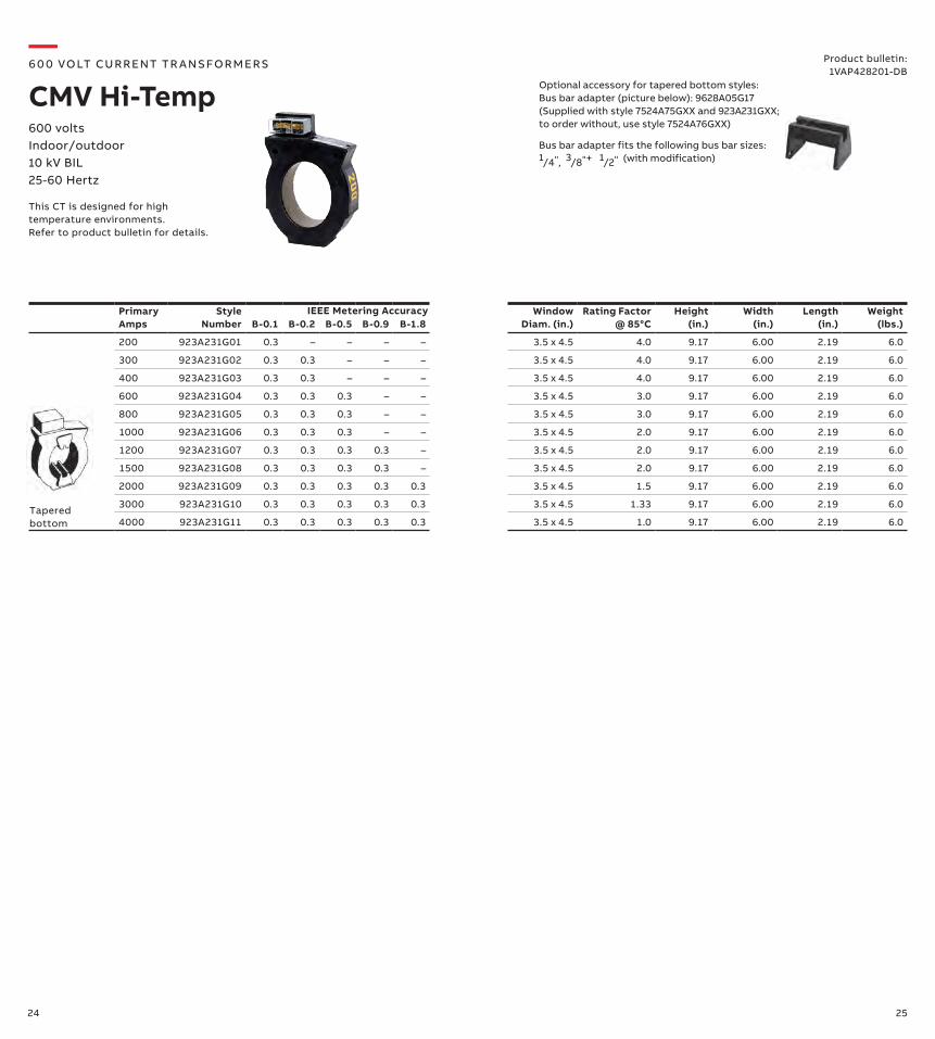
200 923A231G01 0.3 – – – – 3.5 x 4.5 4.0 9.17 6.00 2.19 6.0
300 923A231G02 0.3 0.3 – – – 3.5 x 4.5 4.0 9.17 6.00 2.19 6.0
400 923A231G03 0.3 0.3 – – – 3.5 x 4.5 4.0 9.17 6.00 2.19 6.0
600 923A231G04 0.3 0.3 0.3 – – 3.5 x 4.5 3.0 9.17 6.00 2.19 6.0
800 923A231G05 0.3 0.3 0.3 – – 3.5 x 4.5 3.0 9.17 6.00 2.19 6.0
1000 923A231G06 0.3 0.3 0.3 – – 3.5 x 4.5 2.0 9.17 6.00 2.19 6.0
1200 923A231G07 0.3 0.3 0.3 0.3 – 3.5 x 4.5 2.0 9.17 6.00 2.19 6.0
1500 923A231G08 0.3 0.3 0.3 0.3 – 3.5 x 4.5 2.0 9.17 6.00 2.19 6.0
2000 923A231G09 0.3 0.3 0.3 0.3 0.3 3.5 x 4.5 1.5 9.17 6.00 2.19 6.0
3000 923A231G10 0.3 0.3 0.3 0.3 0.3 3.5 x 4.5 1.33 9.17 6.00 2.19 6.0
4000 923A231G11 0.3 0.3 0.3 0.3 0.3 3.5 x 4.5 1.0 9.17 6.00 2.19 6.0
This CT is designed for high temperature environments. Refer to product bulletin for details.
Tapered bottom
IEEE Metering Accuracy
600 volts Indoor/outdoor 10 kV BIL25-60 Hertz
—6 0 0 VO LT CU R R ENT TR A NS FO R M ER S
CMV Hi-TempProduct bulletin:
1VAP428201-DBOptional accessory for tapered bottom styles:Bus bar adapter (picture below): 9628A05G17 (Supplied with style 7524A75GXX and 923A231GXX; to order without, use style 7524A76GXX)
Bus bar adapter fits the following bus bar sizes: 1/4", 3/8"+ 1/2" (with modification)
26 27
Primary Amps
Style Number B-0.1
B-0.2 B-0.5 B-0.9
B-1.8
Window Diam. (in.)
30°C
55°C
Height (in.)
Width (in.)
Length (in.)
Weight (lbs.)
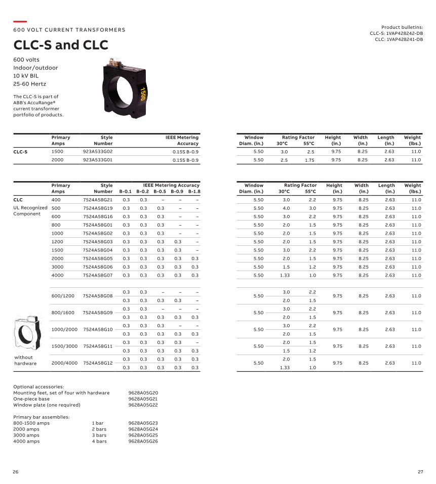
CLC 400 7524A58G21 0.3 0.3 – – – 5.50 3.0 2.2 9.75 8.25 2.63 11.0
500 7524A58G19 0.3 0.3 0.3 – – 5.50 4.0 3.0 9.75 8.25 2.63 11.0
600 7524A58G16 0.3 0.3 0.3 – – 5.50 3.0 2.2 9.75 8.25 2.63 11.0
800 7524A58G01 0.3 0.3 0.3 – – 5.50 2.0 1.5 9.75 8.25 2.63 11.0
1000 7524A58G02 0.3 0.3 0.3 – – 5.50 2.0 1.5 9.75 8.25 2.63 11.0
1200 7524A58G03 0.3 0.3 0.3 0.3 – 5.50 2.0 1.5 9.75 8.25 2.63 11.0
1500 7524A58G04 0.3 0.3 0.3 0.3 – 5.50 3.0 2.2 9.75 8.25 2.63 11.0
2000 7524A58G05 0.3 0.3 0.3 0.3 0.3 5.50 2.0 1.5 9.75 8.25 2.63 11.0
3000 7524A58G06 0.3 0.3 0.3 0.3 0.3 5.50 1.5 1.2 9.75 8.25 2.63 11.0
4000 7524A58G07 0.3 0.3 0.3 0.3 0.3 5.50 1.33 1.0 9.75 8.25 2.63 11.0
600/1200 7524A58G080.3 0.3 – – –
5.503.0 2.2
9.75 8.25 2.63 11.00.3 0.3 0.3 0.3 – 2.0 1.5
800/1600 7524A58G090.3 0.3 – – –
5.503.0 2.2
9.75 8.25 2.63 11.00.3 0.3 0.3 0.3 0.3 2.0 1.5
1000/2000 7524A58G100.3 0.3 0.3 – –
5.503.0 2.2
9.75 8.25 2.63 11.00.3 0.3 0.3 0.3 0.3 2.0 1.5
1500/3000 7524A58G110.3 0.3 0.3 0.3 –
5.502.0 1.5
9.75 8.25 2.63 11.00.3 0.3 0.3 0.3 0.3 1.5 1.2
2000/4000 7524A58G120.3 0.3 0.3 0.3 0.3
5.502.0 1.5
9.75 8.25 2.63 11.00.3 0.3 0.3 0.3 0.3 1.33 1.0
Rating Factor
Product bulletins:CLC-S: 1VAP428242-DB
CLC: 1VAP428241-DB
Optional accessories:Mounting feet, set of four with hardware 9628A05G20One-piece base 9628A05G21Window plate (one required) 9628A05G22
Primary bar assemblies:800-1500 amps 1 bar 9628A05G232000 amps 2 bars 9628A05G243000 amps 3 bars 9628A05G254000 amps 4 bars 9628A05G26
UL Recognized Component
without hardware
IEEE Metering Accuracy
Primary Amps
Style Number
IEEE Metering Accuracy
Window Diam. (in.)
30°C
55°C
Height (in.)
Width (in.)
Length (in.)
Weight (lbs.)
CLC-S 1500 923A533G02 0.15S B-0.9 5.50 3.0 2.5 9.75 8.25 2.63 11.0
2000 923A533G01 0.15S B-0.9 5.50 2.5 1.75 9.75 8.25 2.63 11.0
Rating Factor
600 volts Indoor/outdoor 10 kV BIL25-60 Hertz
—6 0 0 VO LT CU R R ENT TR A NS FO R M ER S
CLC-S and CLC
The CLC-S is part of ABB’s AccuRange® current transformer portfolio of products.
28 29
Primary Amps
Style Number B-0.1
B-0.2 B-0.5 B-0.9
B-1.8
Window Diam. (in.)
30°C
55°C
Height (in.)
Width (in.)
Length (in.)
Weight (lbs.)
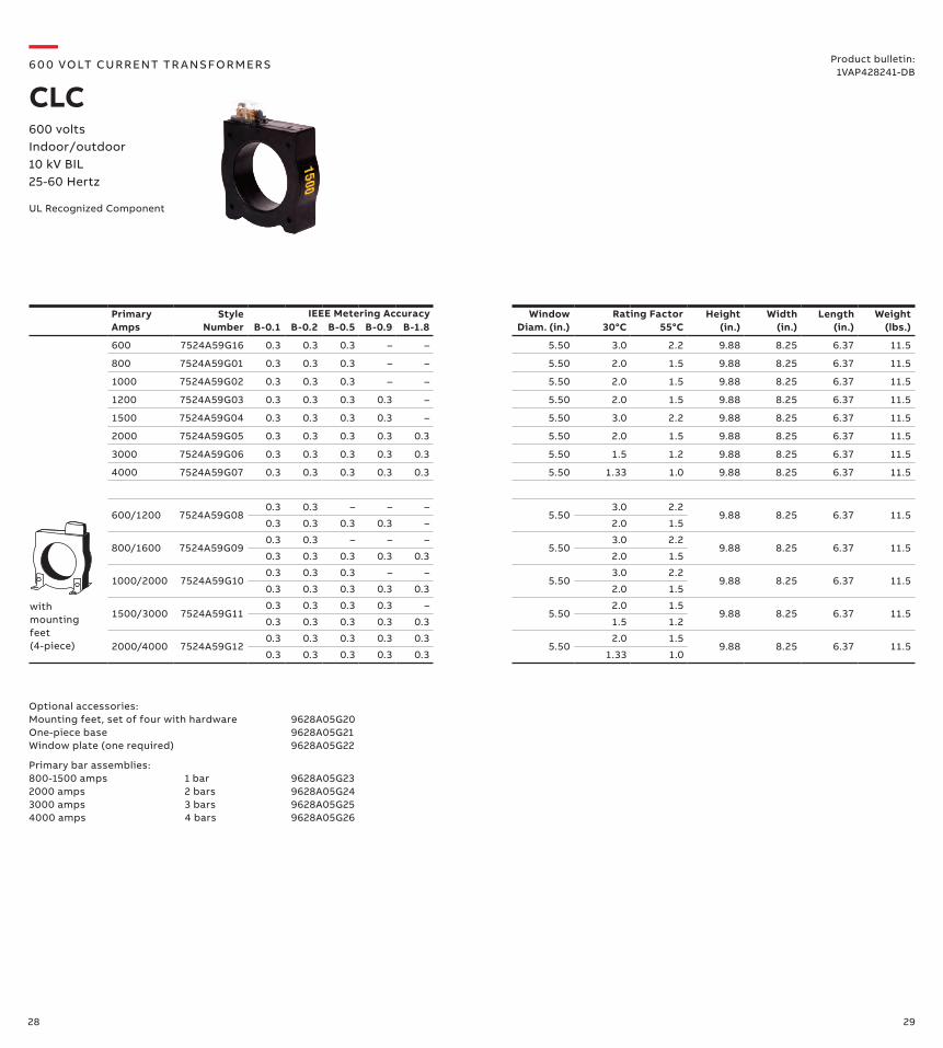
600 7524A59G16 0.3 0.3 0.3 – – 5.50 3.0 2.2 9.88 8.25 6.37 11.5
800 7524A59G01 0.3 0.3 0.3 – – 5.50 2.0 1.5 9.88 8.25 6.37 11.5
1000 7524A59G02 0.3 0.3 0.3 – – 5.50 2.0 1.5 9.88 8.25 6.37 11.5
1200 7524A59G03 0.3 0.3 0.3 0.3 – 5.50 2.0 1.5 9.88 8.25 6.37 11.5
1500 7524A59G04 0.3 0.3 0.3 0.3 – 5.50 3.0 2.2 9.88 8.25 6.37 11.5
2000 7524A59G05 0.3 0.3 0.3 0.3 0.3 5.50 2.0 1.5 9.88 8.25 6.37 11.5
3000 7524A59G06 0.3 0.3 0.3 0.3 0.3 5.50 1.5 1.2 9.88 8.25 6.37 11.5
4000 7524A59G07 0.3 0.3 0.3 0.3 0.3 5.50 1.33 1.0 9.88 8.25 6.37 11.5
600/1200 7524A59G080.3 0.3 – – –
5.503.0 2.2
9.88 8.25 6.37 11.50.3 0.3 0.3 0.3 – 2.0 1.5
800/1600 7524A59G090.3 0.3 – – –
5.503.0 2.2
9.88 8.25 6.37 11.50.3 0.3 0.3 0.3 0.3 2.0 1.5
1000/2000 7524A59G100.3 0.3 0.3 – –
5.503.0 2.2
9.88 8.25 6.37 11.50.3 0.3 0.3 0.3 0.3 2.0 1.5
1500/3000 7524A59G110.3 0.3 0.3 0.3 –
5.502.0 1.5
9.88 8.25 6.37 11.50.3 0.3 0.3 0.3 0.3 1.5 1.2
2000/4000 7524A59G120.3 0.3 0.3 0.3 0.3
5.502.0 1.5
9.88 8.25 6.37 11.50.3 0.3 0.3 0.3 0.3 1.33 1.0
Rating Factor
UL Recognized Component
withmounting feet (4-piece)
IEEE Metering Accuracy
600 volts Indoor/outdoor 10 kV BIL25-60 Hertz
—6 0 0 VO LT CU R R ENT TR A NS FO R M ER S
CLCProduct bulletin:
1VAP428241-DB
Optional accessories:Mounting feet, set of four with hardware 9628A05G20One-piece base 9628A05G21Window plate (one required) 9628A05G22
Primary bar assemblies:800-1500 amps 1 bar 9628A05G232000 amps 2 bars 9628A05G243000 amps 3 bars 9628A05G254000 amps 4 bars 9628A05G26

30 31
Primary Amps
Style Number B-0.1
B-0.2 B-0.5 B-0.9
B-1.8
Window Diam. (in.)
30°C
55°C
Height (in.)
Width (in.)
Length (in.)
Weight (lbs.)
400 7524A60G18 0.3 0.3 – – – 5.50 3.0 2.2 9.88 10.50 2.62 11.0
500 7524A60G19 0.3 0.3 0.3 – – 5.50 4.0 3.0 9.88 10.50 2.62 11.0
600 7524A60G16 0.3 0.3 0.3 – – 5.50 3.0 2.2 9.88 10.50 2.62 11.0
800 7524A60G01 0.3 0.3 0.3 – – 5.50 2.0 1.5 9.88 10.50 2.62 11.0
1000 7524A60G02 0.3 0.3 0.3 – – 5.50 2.0 1.5 9.88 10.50 2.62 11.0
1200 7524A60G03 0.3 0.3 0.3 0.3 – 5.50 2.0 1.5 9.88 10.50 2.62 11.0
1500 7524A60G04 0.3 0.3 0.3 0.3 – 5.50 3.0 2.2 9.88 10.50 2.62 11.0
2000 7524A60G05 0.3 0.3 0.3 0.3 0.3 5.50 2.0 1.5 9.88 10.50 2.62 11.0
3000 7524A60G06 0.3 0.3 0.3 0.3 0.3 5.50 1.5 1.2 9.88 10.50 2.62 11.0
4000 7524A60G07 0.3 0.3 0.3 0.3 0.3 5.50 1.33 1.0 9.88 10.50 2.62 11.0
600/1200 7524A60G080.3 0.3 – – –
5.503.0 2.2
9.88 10.50 2.62 11.00.3 0.3 0.3 0.3 – 2.0 1.5
800/1600 7524A60G090.3 0.3 – – –
5.503.0 2.2
9.88 10.50 2.62 11.00.3 0.3 0.3 0.3 0.3 2.0 1.5
1000/2000 7524A60G100.3 0.3 0.3 – –
5.503.0 2.2
9.88 10.50 2.62 11.00.3 0.3 0.3 0.3 0.3 2.0 1.5
1500/3000 7524A60G110.3 0.3 0.3 0.3 –
5.502.0 1.5
9.88 10.50 2.62 11.00.3 0.3 0.3 0.3 0.3 1.5 1.2
2000/4000 7524A60G120.3 0.3 0.3 0.3 0.3
5.502.0 1.5
9.88 10.50 2.62 11.00.3 0.3 0.3 0.3 0.3 1.33 1.0
Optional accessories:Mounting feet-set of four with hardware 9628A05G20One-piece base 9628A05G21Window plate (one required) 9628A05G22
Primary bar assemblies:800-1500 amps 1 bar 9628A05G232000 amps 2 bars 9628A05G243000 amps 3 bars 9628A05G254000 amps 4 bars 9628A05G26
with one piece base
UL Recognized Component
600 volts Indoor/outdoor 10 kV BIL25-60 Hertz
—6 0 0 VO LT CU R R ENT TR A NS FO R M ER S
CLCProduct bulletin:
1VAP428241-DB
Rating FactorIEEE Metering Accuracy
32 33
Primary Amps
Style Number B-0.1
B-0.2 B-0.5 B-0.9
B-1.8
Window Diam. (in.)
30°C
55°C
Height (in.)
Width (in.)
Length (in.)
Weight (lbs.)
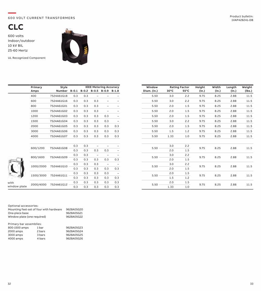
400 7524A61G18 0.3 0.3 – – – 5.50 3.0 2.2 9.75 8.25 2.88 11.5
600 7524A61G16 0.3 0.3 0.3 – – 5.50 3.0 2.2 9.75 8.25 2.88 11.5
800 7524A61G01 0.3 0.3 0.3 – – 5.50 2.0 1.5 9.75 8.25 2.88 11.5
1000 7524A61G02 0.3 0.3 0.3 – – 5.50 2.0 1.5 9.75 8.25 2.88 11.5
1200 7524A61G03 0.3 0.3 0.3 0.3 – 5.50 2.0 1.5 9.75 8.25 2.88 11.5
1500 7524A61G04 0.3 0.3 0.3 0.3 – 5.50 3.0 2.2 9.75 8.25 2.88 11.5
2000 7524A61G05 0.3 0.3 0.3 0.3 0.3 5.50 2.0 1.5 9.75 8.25 2.88 11.5
3000 7524A61G06 0.3 0.3 0.3 0.3 0.3 5.50 1.5 1.2 9.75 8.25 2.88 11.5
4000 7524A61G07 0.3 0.3 0.3 0.3 0.3 5.50 1.33 1.0 9.75 8.25 2.88 11.5
600/1200 7524A61G080.3 0.3 – – –
5.503.0 2.2
9.75 8.25 2.88 11.50.3 0.3 0.3 0.3 – 2.0 1.5
800/1600 7524A61G090.3 0.3 – – –
5.503.0 2.2
9.75 8.25 2.88 11.50.3 0.3 0.3 0.3 0.3 2.0 1.5
1000/2000 7524A61G100.3 0.3 0.3 – –
5.503.0 2.2
9.75 8.25 2.88 11.50.3 0.3 0.3 0.3 0.3 2.0 1.5
1500/3000 7524A61G110.3 0.3 0.3 0.3 –
5.502.0 1.5
9.75 8.25 2.88 11.50.3 0.3 0.3 0.3 0.3 1.5 1.2
2000/4000 7524A61G120.3 0.3 0.3 0.3 0.3
5.502.0 1.5
9.75 8.25 2.88 11.50.3 0.3 0.3 0.3 0.3 1.33 1.0
with window plate
UL Recognized Component
600 volts Indoor/outdoor 10 kV BIL25-60 Hertz
—6 0 0 VO LT CU R R ENT TR A NS FO R M ER S
CLCProduct bulletin:
1VAP428241-DB
Optional accessories:Mounting feet-set of four with hardware 9628A05G20One-piece base 9628A05G21Window plate (one required) 9628A05G22
Primary bar assemblies:800-1500 amps 1 bar 9628A05G232000 amps 2 bars 9628A05G243000 amps 3 bars 9628A05G254000 amps 4 bars 9628A05G26
Rating FactorIEEE Metering Accuracy
34 35
Primary Amps
Style Number B-0.1
B-0.2 B-0.5 B-0.9
B-1.8
Number of Bars 30°C
55°C
Height (in.)
Width (in.)
Length (in.)
Weight (lbs.)
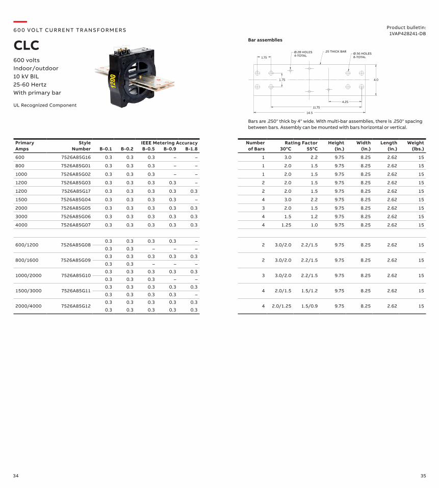
600 7526A85G16 0.3 0.3 0.3 – – 1 3.0 2.2 9.75 8.25 2.62 15
800 7526A85G01 0.3 0.3 0.3 – – 1 2.0 1.5 9.75 8.25 2.62 15
1000 7526A85G02 0.3 0.3 0.3 – – 1 2.0 1.5 9.75 8.25 2.62 15
1200 7526A85G03 0.3 0.3 0.3 0.3 – 2 2.0 1.5 9.75 8.25 2.62 15
1200 7526A85G17 0.3 0.3 0.3 0.3 0.3 2 2.0 1.5 9.75 8.25 2.62 15
1500 7526A85G04 0.3 0.3 0.3 0.3 – 4 3.0 2.2 9.75 8.25 2.62 15
2000 7526A85G05 0.3 0.3 0.3 0.3 0.3 3 2.0 1.5 9.75 8.25 2.62 15
3000 7526A85G06 0.3 0.3 0.3 0.3 0.3 4 1.5 1.2 9.75 8.25 2.62 15
4000 7526A85G07 0.3 0.3 0.3 0.3 0.3 4 1.25 1.0 9.75 8.25 2.62 15
600/1200 7526A85G080.3 0.3 0.3 0.3 –
2 3.0/2.0 2.2/1.5 9.75 8.25 2.62 150.3 0.3 – – –
800/1600 7526A85G090.3 0.3 0.3 0.3 0.3
2 3.0/2.0 2.2/1.5 9.75 8.25 2.62 150.3 0.3 – – –
1000/2000 7526A85G100.3 0.3 0.3 0.3 0.3
3 3.0/2.0 2.2/1.5 9.75 8.25 2.62 150.3 0.3 0.3 – –
1500/3000 7526A85G110.3 0.3 0.3 0.3 0.3
4 2.0/1.5 1.5/1.2 9.75 8.25 2.62 150.3 0.3 0.3 0.3 –
2000/4000 7526A85G120.3 0.3 0.3 0.3 0.3
4 2.0/1.25 1.5/0.9 9.75 8.25 2.62 150.3 0.3 0.3 0.3 0.3
4.0
1.75
4.25
11.75
14.5
1.75
.25 THICK BARØ.56 HOLES8-TOTAL
Ø.28 HOLES4-TOTAL
Bar assemblies
Bars are .250" thick by 4" wide. With multi-bar assemblies, there is .250" spacing between bars. Assembly can be mounted with bars horizontal or vertical.
Rating FactorIEEE Metering Accuracy
Product bulletin:1VAP428241-DB
UL Recognized Component
600 volts Indoor/outdoor 10 kV BIL25-60 HertzWith primary bar
—6 0 0 VO LT CU R R ENT TR A NS FO R M ER S
CLC
36 37
Primary Amps
Style Number Metering Relaying
WindowDiam. (in.)
Rating Factor @ 30°C
Height (in.)
Width (in.)
Length (in.)
Weight (lbs.)
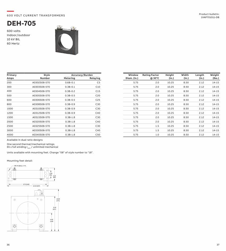
200 A0302S08-570 0.6B-0.1 C5 5.75 2.0 10.25 8.50 2.12 14-15
300 A0303S08-570 0.3B-0.1 C10 5.75 2.0 10.25 8.50 2.12 14-15
400 A0304S08-570 0.3B-0.2 C15 5.75 2.0 10.25 8.50 2.12 14-15
500 A0305S08-570 0.3B-0.5 C20 5.75 2.0 10.25 8.50 2.12 14-15
600 A0306S08-570 0.3B-0.5 C25 5.75 2.0 10.25 8.50 2.12 14-15
800 A0308S08-570 0.3B-0.9 C30 5.75 2.0 10.25 8.50 2.12 14-15
1000 A0310S08-570 0.3B-0.9 C30 5.75 2.0 10.25 8.50 2.12 14-15
1200 A0312S08-570 0.3B-0.9 C40 5.75 2.0 10.25 8.50 2.12 14-15
1500 A0315S08-570 0.3B-1.8 C30 5.75 2.0 10.25 8.50 2.12 14-15
2000 A0320S08-570 0.3B-1.8 C40 5.75 2.0 10.25 8.50 2.12 14-15
2500 A0325S08-570 0.3B-1.8 C30 5.75 1.5 10.25 8.50 2.12 14-15
3000 A0330S08-570 0.3B-1.8 C40 5.75 1.5 10.25 8.50 2.12 14-15
4000 A0340S08-570 0.3B-1.8 C50 5.75 1.0 10.25 8.50 2.12 14-15
Accuracy/Burden
Available in dual ratio designs
One second thermal/mechanical ratings: 65 x full winding Inom / unlimited mechanical
Units available with mounting feet. Change “08” of style number to “18”.
600 volts Indoor/outdoor 10 kV BIL60 Hertz
—6 0 0 VO LT CU R R ENT TR A NS FO R M ER S
DEH-705Product bulletin:
1VAP701011-DB
Mounting feet detail:
10.50 [267]
4.69
8.94
10.69
9.75 [248]
2.00
3.25
Ø0.44 [Ø11] x 4 PL
[51]
[82]
[272]
[227]
[119]

38 39
2000 7524A64G01 0.3 0.3 0.3 0.3 – 8.25 C50 2.0 1.5 12.88 11.38 6.37 17.0
3000 7524A64G02 0.3 0.3 0.3 0.3 0.3 8.25 C100 2.0 1.5 12.88 11.38 6.37 17.0
4000 7524A64G03 0.3 0.3 0.3 0.3 0.3 8.25 C100 1.5 1.2 12.88 11.38 6.37 17.0
5000 7524A64G04 0.3 0.3 0.3 0.3 0.3 8.25 C100 1.33 1.0 12.88 11.38 6.37 17.0
6000 7524A64G05 0.3 0.3 0.3 0.3 0.3 8.25 – 1.0 0.75 12.88 11.38 6.37 17.0
1000/2000 7524A64G060.3 0.3 0.3 – –
8.25C30 3.0 2.2
12.88 11.38 6.37 17.00.3 0.3 0.3 0.3 – C50 2.0 1.5
1500/3000 7524A64G070.3 0.3 0.3 – –
8.25C50 3.0 2.2
12.88 11.38 6.37 17.00.3 0.3 0.3 0.3 0.3 C100 2.0 1.5
2000/4000 7524A64G080.3 0.3 0.3 0.3 –
8.25C50 2.0 1.5
12.88 11.38 6.37 17.00.3 0.3 0.3 0.3 0.3 C100 1.5 1.2
2500/5000 7524A64G090.3 0.3 0.3 0.3 0.3
8.25C100 2.0 1.5
12.88 11.38 6.37 17.00.3 0.3 0.3 0.3 0.3 C200 1.33 1.0
3000/6000 7524A64G100.3 0.3 0.3 0.3 0.3
8.25– 1.33 1.0
12.88 11.38 6.37 17.00.3 0.3 0.3 0.3 0.3 – 1.0 0.75
Primary Amps
Style Number B-0.1
B-0.2 B-0.5 B-0.9
B-1.8
Window Diam. (in.)
Relaying Accuracy
30°C
55°C
Height (in.)
Width (in.)
Length (in.)
Weight (lbs.)
2000 7524A63G01 0.3 0.3 0.3 0.3 – 8.25 C50 2.0 1.5 12.88 11.38 2.63 16.0
3000 7524A63G02 0.3 0.3 0.3 0.3 0.3 8.25 C100 2.0 1.5 12.88 11.38 2.63 16.0
4000 7524A63G03 0.3 0.3 0.3 0.3 0.3 8.25 C100 1.5 1.2 12.88 11.38 2.63 16.0
5000 7524A63G04 0.3 0.3 0.3 0.3 0.3 8.25 C100 1.33 1.0 12.88 11.38 2.63 16.0
6000 7524A63G05 0.3 0.3 0.3 0.3 0.3 8.25 – 1.0 0.75 12.88 11.38 2.63 16.0
1000/2000 7524A63G060.3 0.3 0.3 – –
8.25C30 3.0 2.2
12.88 11.38 2.63 16.00.3 0.3 0.3 0.3 – C50 2.0 1.5
1500/3000 7524A63G070.3 0.3 0.3 – –
8.25C50 3.0 2.2
12.88 11.38 2.63 16.00.3 0.3 0.3 0.3 0.3 C100 2.0 1.5
2000/4000 7524A63G080.3 0.3 0.3 0.3 –
8.25C50 2.0 1.5
12.88 11.38 2.63 16.00.3 0.3 0.3 0.3 0.3 C100 1.5 1.2
2500/5000 7524A63G090.3 0.3 0.3 0.3 0.3
8.25C100 2.0 1.5
12.88 11.38 2.63 16.00.3 0.3 0.3 0.3 0.3 C200 1.33 1.0
3000/6000 7524A63G100.3 0.3 0.3 0.3 0.3
8.25– 1.33 1.0
12.88 11.38 2.63 16.00.3 0.3 0.3 0.3 0.3 – 1.0 0.75
Rating Factor
Optional accessories:Mounting feet (set of 2 with hardware) 9628A05G27Window plates (set of 2 with hardware) 9628A05G28
IEEE Metering Accuracy
without mounting feet
with mounting feet(2-piece)
UL Recognized Component
600 volts Indoor/outdoor 10 kV BIL25-400 Hertz
—6 0 0 VO LT CU R R ENT TR A NS FO R M ER S
CLEProduct bulletin:
1VAP428261-DB
40 41
Primary Amps
Style Number Metering Relaying
WindowDiam. (in.)
Rating Factor @ 30°C
Height (in.)
Width (in.)
Length (in.)
Weight (lbs.)
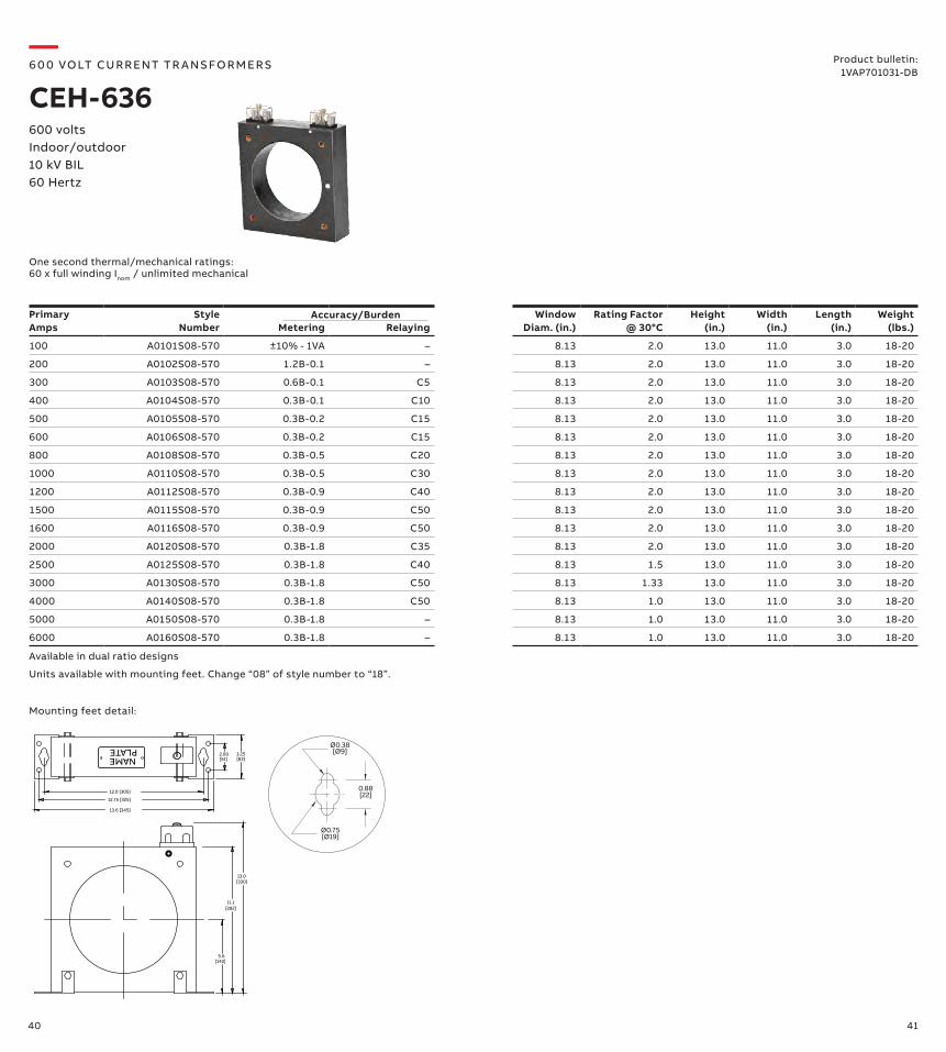
100 A0101S08-570 ±10% - 1VA – 8.13 2.0 13.0 11.0 3.0 18-20
200 A0102S08-570 1.2B-0.1 – 8.13 2.0 13.0 11.0 3.0 18-20
300 A0103S08-570 0.6B-0.1 C5 8.13 2.0 13.0 11.0 3.0 18-20
400 A0104S08-570 0.3B-0.1 C10 8.13 2.0 13.0 11.0 3.0 18-20
500 A0105S08-570 0.3B-0.2 C15 8.13 2.0 13.0 11.0 3.0 18-20
600 A0106S08-570 0.3B-0.2 C15 8.13 2.0 13.0 11.0 3.0 18-20
800 A0108S08-570 0.3B-0.5 C20 8.13 2.0 13.0 11.0 3.0 18-20
1000 A0110S08-570 0.3B-0.5 C30 8.13 2.0 13.0 11.0 3.0 18-20
1200 A0112S08-570 0.3B-0.9 C40 8.13 2.0 13.0 11.0 3.0 18-20
1500 A0115S08-570 0.3B-0.9 C50 8.13 2.0 13.0 11.0 3.0 18-20
1600 A0116S08-570 0.3B-0.9 C50 8.13 2.0 13.0 11.0 3.0 18-20
2000 A0120S08-570 0.3B-1.8 C35 8.13 2.0 13.0 11.0 3.0 18-20
2500 A0125S08-570 0.3B-1.8 C40 8.13 1.5 13.0 11.0 3.0 18-20
3000 A0130S08-570 0.3B-1.8 C50 8.13 1.33 13.0 11.0 3.0 18-20
4000 A0140S08-570 0.3B-1.8 C50 8.13 1.0 13.0 11.0 3.0 18-20
5000 A0150S08-570 0.3B-1.8 – 8.13 1.0 13.0 11.0 3.0 18-20
6000 A0160S08-570 0.3B-1.8 – 8.13 1.0 13.0 11.0 3.0 18-20
Accuracy/Burden
Available in dual ratio designs
One second thermal/mechanical ratings: 60 x full winding Inom / unlimited mechanical
Units available with mounting feet. Change “08” of style number to “18”.
600 volts Indoor/outdoor 10 kV BIL60 Hertz
—6 0 0 VO LT CU R R ENT TR A NS FO R M ER S
CEH-636Product bulletin:
1VAP701031-DB
Mounting feet detail:
5.6
11.1
13.0
12.0 [305]
12.75 [325]
13.6 [345]
[142]
[282]
[330]
NAMEPLATE
2.00[51]
3.25[83]
0.88
[Ø9]
Ø0.75
Ø0.38
[22]
[Ø19]

42 43
Primary Amps
Style Number B-0.1
B-0.2 B-0.5 B-0.9
B-1.8
Window Diam. (in.)
Relaying Accuracy
30°C
55°C
Height (in.)
Width (in.)
Length (in.)
Weight (lbs.)
RLC 500 7524A52G23 0.3 0.3 0.3 – – 5.5 C50 2.0 1.5 11.25 10.50 4.12 21.0
600 7524A52G17 0.3 0.3 0.3 – – 5.5 C100 2.0 1.5 11.25 10.50 4.12 21.0
750 7524A52G01 0.3 0.3 0.3 – – 5.5 C100 2.0 1.5 11.25 10.50 4.12 21.0
800 7524A52G02 0.3 0.3 0.3 0.3 – 5.5 C100 2.0 1.5 11.25 10.50 4.12 21.0
900 7524A52G03 0.3 0.3 0.3 0.3 – 5.5 C100 2.0 1.5 11.25 10.50 4.12 21.0
1000 7524A52G04 0.3 0.3 0.3 0.3 – 5.5 C100 2.0 1.5 11.25 10.50 4.12 21.0
1200 7524A52G05 0.3 0.3 0.3 0.3 0.3 5.5 C200 2.0 1.5 11.25 10.50 4.12 21.0
1500 7524A52G06 0.3 0.3 0.3 0.3 0.3 5.5 C200 2.0 1.5 11.25 10.50 4.12 21.0
2000 7524A52G07 0.3 0.3 0.3 0.3 0.3 5.5 C200 1.5 1.2 11.25 10.50 4.12 21.0
3000 7524A52G08 0.3 0.3 0.3 0.3 0.3 5.5 C200 1.33 1.0 11.25 10.50 4.12 21.0
4000 7524A52G09 0.3 0.3 0.3 0.3 0.3 5.5 C200 1.33 1.0 11.25 10.50 4.12 21.0
600/1200 7524A52G100.3 0.3 0.3 – –
5.5C100 2.0 1.5
11.25 10.50 4.12 21.00.3 0.3 0.3 0.3 0.3 C200 2.0 1.5
800/1600 7524A52G110.3 0.3 0.3 – –
5.5C100 2.0 1.5
11.25 10.50 4.12 21.00.3 0.3 0.3 0.3 0.3 C200 1.5 1.2
1000/2000 7524A52G120.3 0.3 0.3 0.3 –
5.5C100 2.0 1.5
11.25 10.50 4.12 21.00.3 0.3 0.3 0.3 0.3 C200 1.5 1.2
1500/3000 7524A52G130.3 0.3 0.3 0.3 0.3
5.5C100 1.5 1.2
11.25 10.50 4.12 21.00.3 0.3 0.3 0.3 0.3 C200 1.33 1.0
2000/4000 7524A52G140.3 0.3 0.3 0.3 0.3
5.5C100 1.5 1.2
11.25 10.50 4.12 21.00.3 0.3 0.3 0.3 0.3 C200 1.33 1.0
Rating Factor
4.50
4.88
10.50
1.00
4.13
Ø.313 HOLE4-TOTAL
.375 x 1.250 SLOTW .750 HOLE
2-TOTAL
IEEE Metering Accuracy
RLC HighAccuracy
300 9625A21G10 0.3 – – – – 5.5 C90 2.0 1.5 11.25 10.50 4.12 29.0
800 9625A21G11 - - - - - 5.5 C200 2.0 1.5 11.25 10.50 4.12 29.0
1000 9625A21G01 0.3 0.3 0.3 0.3 0.3 5.5 C200 2.0 1.5 11.25 10.50 4.12 29.0
2000 9625A21G02 0.3 0.3 0.3 0.3 0.3 5.5 C400 1.5 1.2 11.25 10.50 4.12 29.0
3000 9625A21G03 0.3 0.3 0.3 0.3 0.3 5.5 C400 1.5 1.2 11.25 10.50 4.12 29.0
4000 9625A21G04 0.3 0.3 0.3 0.3 0.3 5.5 C400 1.5 1.2 11.25 10.50 4.12 29.0
1000/2000 9625A21G050.3 0.3 0.3 0.3 –
5.5C200 2.0 1.5
11.25 10.50 4.12 29.00.3 0.3 0.3 0.3 0.3 C400 1.5 1.2
1500/3000 9625A21G060.3 0.3 0.3 0.3 0.3
5.5C200 1.5 1.2
11.25 10.50 4.12 29.00.3 0.3 0.3 0.3 0.3 C400 1.33 1.0
2000/4000 9625A21G070.3 0.3 0.3 0.3 0.3
5.5C200 1.5 1.2
11.25 10.50 4.12 29.00.3 0.3 0.3 0.3 0.3 C400 1.33 1.0
UL Recognized Component
600 volts Indoor/outdoor 10 kV BIL25-60 Hertz
—6 0 0 VO LT CU R R ENT TR A NS FO R M ER S
RLCProduct bulletin:
1VAP428281-DB
Contact your ABB representative for styles with primary bar.
Dimensions (in.)
44 45
13.36
9.50
4.63
2.66
4.28
.25
Ø5.50
MOUNTING HOLESFOR .38 BOLTS4-TOTAL
NAMEPLATE
RATINGDECALBOTHSIDES
CLAMP TYPE SECONDARY TERMINALSFOR #14 TO #3 WIRE
1" STD. PIPE TAPBOTH SIDED
5.31
8.56
4.13
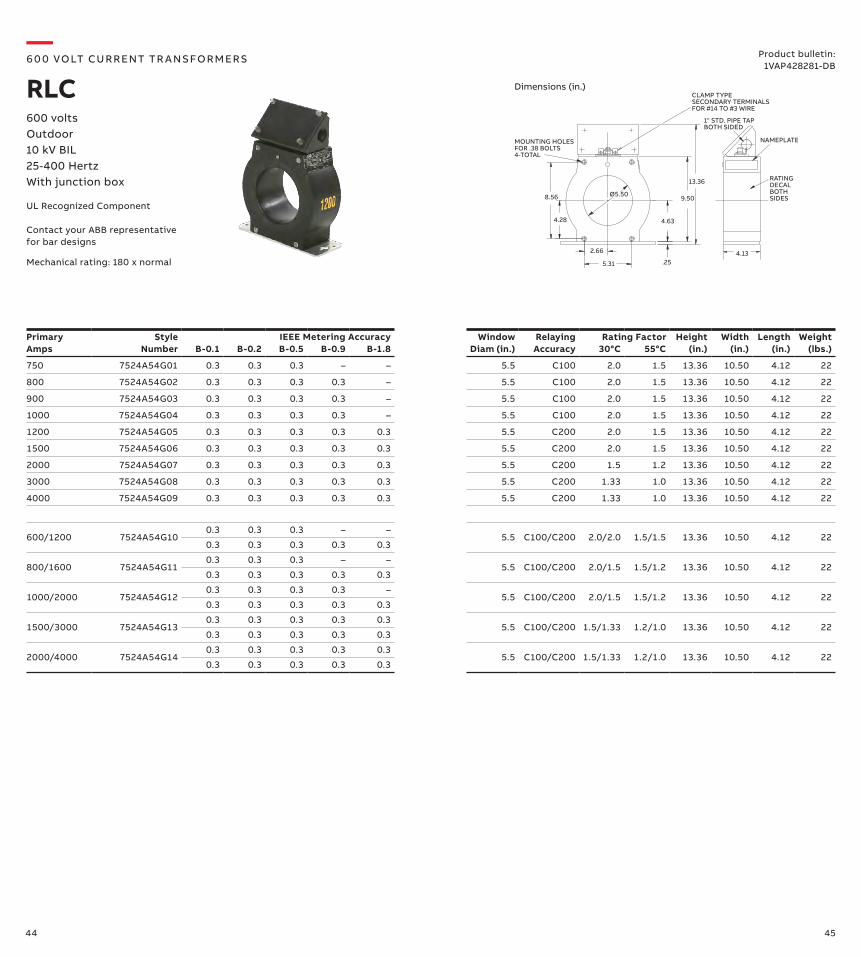
Rating FactorPrimary Amps
Style Number B-0.1
B-0.2 B-0.5 B-0.9
B-1.8
Window Diam (in.)
Relaying Accuracy
30°C
55°C
Height (in.)
Width (in.)
Length (in.)
Weight (lbs.)
750 7524A54G01 0.3 0.3 0.3 – – 5.5 C100 2.0 1.5 13.36 10.50 4.12 22
800 7524A54G02 0.3 0.3 0.3 0.3 – 5.5 C100 2.0 1.5 13.36 10.50 4.12 22
900 7524A54G03 0.3 0.3 0.3 0.3 – 5.5 C100 2.0 1.5 13.36 10.50 4.12 22
1000 7524A54G04 0.3 0.3 0.3 0.3 – 5.5 C100 2.0 1.5 13.36 10.50 4.12 22
1200 7524A54G05 0.3 0.3 0.3 0.3 0.3 5.5 C200 2.0 1.5 13.36 10.50 4.12 22
1500 7524A54G06 0.3 0.3 0.3 0.3 0.3 5.5 C200 2.0 1.5 13.36 10.50 4.12 22
2000 7524A54G07 0.3 0.3 0.3 0.3 0.3 5.5 C200 1.5 1.2 13.36 10.50 4.12 22
3000 7524A54G08 0.3 0.3 0.3 0.3 0.3 5.5 C200 1.33 1.0 13.36 10.50 4.12 22
4000 7524A54G09 0.3 0.3 0.3 0.3 0.3 5.5 C200 1.33 1.0 13.36 10.50 4.12 22
600/1200 7524A54G100.3 0.3 0.3 – –
5.5 C100/C200 2.0/2.0 1.5/1.5 13.36 10.50 4.12 220.3 0.3 0.3 0.3 0.3
800/1600 7524A54G110.3 0.3 0.3 – –
5.5 C100/C200 2.0/1.5 1.5/1.2 13.36 10.50 4.12 220.3 0.3 0.3 0.3 0.3
1000/2000 7524A54G120.3 0.3 0.3 0.3 –
5.5 C100/C200 2.0/1.5 1.5/1.2 13.36 10.50 4.12 220.3 0.3 0.3 0.3 0.3
1500/3000 7524A54G130.3 0.3 0.3 0.3 0.3
5.5 C100/C200 1.5/1.33 1.2/1.0 13.36 10.50 4.12 220.3 0.3 0.3 0.3 0.3
2000/4000 7524A54G140.3 0.3 0.3 0.3 0.3
5.5 C100/C200 1.5/1.33 1.2/1.0 13.36 10.50 4.12 220.3 0.3 0.3 0.3 0.3
IEEE Metering Accuracy
UL Recognized Component
Contact your ABB representative for bar designs
600 volts Outdoor 10 kV BIL25-400 HertzWith junction box
—6 0 0 VO LT CU R R ENT TR A NS FO R M ER S
RLCProduct bulletin:
1VAP428281-DB
Mechanical rating: 180 x normal
Dimensions (in.)
46 47
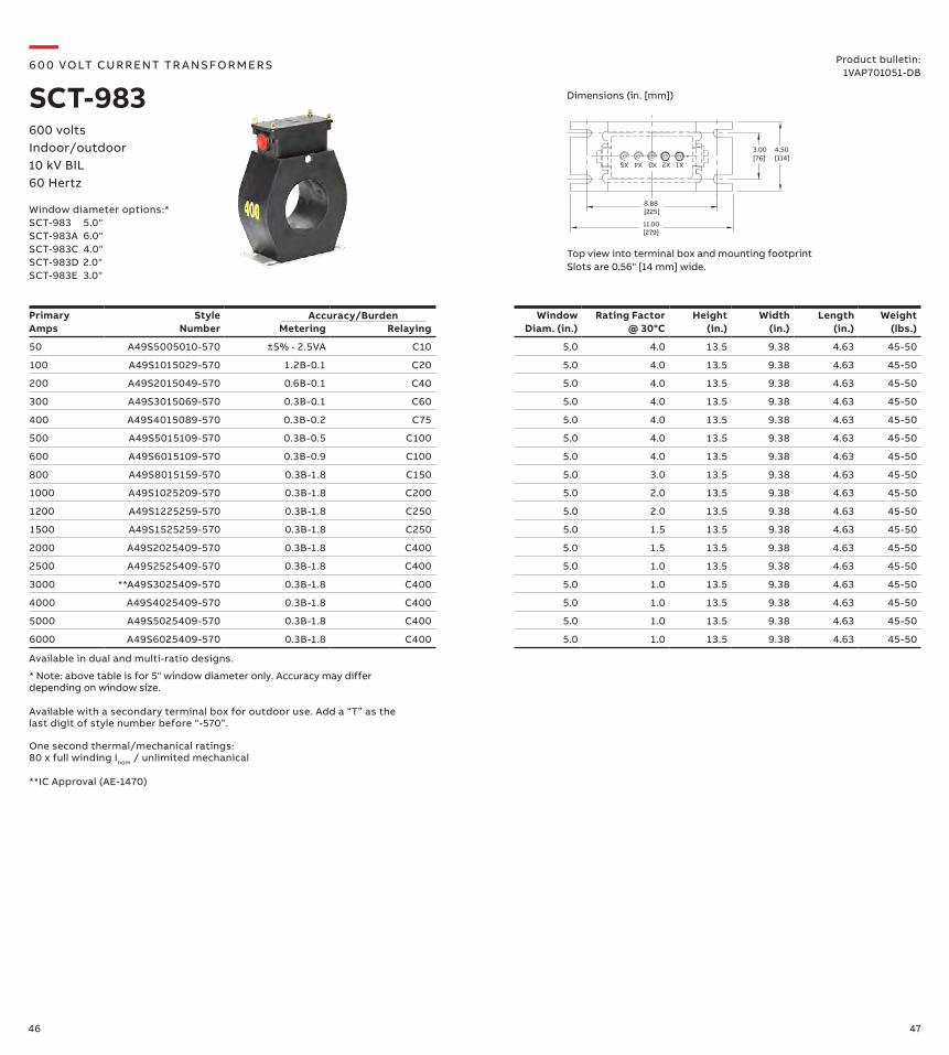
Top view into terminal box and mounting footprintSlots are 0.56" [14 mm] wide.
X1X5 X4 X3 X2
4.50
11.00 [279]
8.88 [225]
3.00[76] [114]
Primary Amps
Style Number Metering Relaying
WindowDiam. (in.)
Rating Factor @ 30°C
Height (in.)
Width (in.)
Length (in.)
Weight (lbs.)
50 A49S5005010-570 ±5% - 2.5VA C10 5.0 4.0 13.5 9.38 4.63 45-50
100 A49S1015029-570 1.2B-0.1 C20 5.0 4.0 13.5 9.38 4.63 45-50
200 A49S2015049-570 0.6B-0.1 C40 5.0 4.0 13.5 9.38 4.63 45-50
300 A49S3015069-570 0.3B-0.1 C60 5.0 4.0 13.5 9.38 4.63 45-50
400 A49S4015089-570 0.3B-0.2 C75 5.0 4.0 13.5 9.38 4.63 45-50
500 A49S5015109-570 0.3B-0.5 C100 5.0 4.0 13.5 9.38 4.63 45-50
600 A49S6015109-570 0.3B-0.9 C100 5.0 4.0 13.5 9.38 4.63 45-50
800 A49S8015159-570 0.3B-1.8 C150 5.0 3.0 13.5 9.38 4.63 45-50
1000 A49S1025209-570 0.3B-1.8 C200 5.0 2.0 13.5 9.38 4.63 45-50
1200 A49S1225259-570 0.3B-1.8 C250 5.0 2.0 13.5 9.38 4.63 45-50
1500 A49S1525259-570 0.3B-1.8 C250 5.0 1.5 13.5 9.38 4.63 45-50
2000 A49S2025409-570 0.3B-1.8 C400 5.0 1.5 13.5 9.38 4.63 45-50
2500 A49S2525409-570 0.3B-1.8 C400 5.0 1.0 13.5 9.38 4.63 45-50
3000 **A49S3025409-570 0.3B-1.8 C400 5.0 1.0 13.5 9.38 4.63 45-50
4000 A49S4025409-570 0.3B-1.8 C400 5.0 1.0 13.5 9.38 4.63 45-50
5000 A49S5025409-570 0.3B-1.8 C400 5.0 1.0 13.5 9.38 4.63 45-50
6000 A49S6025409-570 0.3B-1.8 C400 5.0 1.0 13.5 9.38 4.63 45-50
Accuracy/Burden
Available in dual and multi-ratio designs.
Available with a secondary terminal box for outdoor use. Add a “T” as the last digit of style number before “-570”.
**IC Approval (AE-1470)
One second thermal/mechanical ratings: 80 x full winding Inom / unlimited mechanical
Window diameter options:*SCT-983 5.0"SCT-983A 6.0"SCT-983C 4.0"SCT-983D 2.0"SCT-983E 3.0"
* Note: above table is for 5" window diameter only. Accuracy may differ depending on window size.
600 volts Indoor/outdoor 10 kV BIL60 Hertz
—6 0 0 VO LT CU R R ENT TR A NS FO R M ER S
SCT-983Product bulletin:
1VAP701051-DB
Dimensions (in. [mm])
48 49
Primary Amps
Style Number
IEEE Metering Accuracy
Window Diam. (in.)
Relaying Accuracy Rating Factor @ 30°C
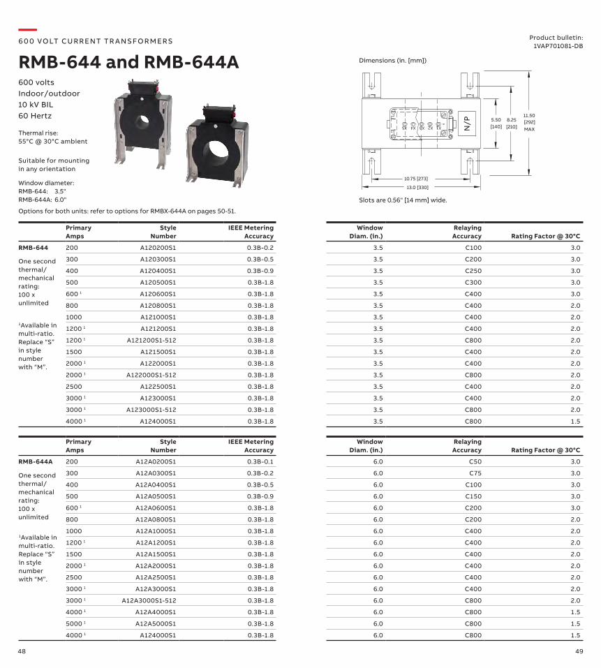
RMB-644 200 A120200S1 0.3B-0.2 3.5 C100 3.0
300 A120300S1 0.3B-0.5 3.5 C200 3.0
400 A120400S1 0.3B-0.9 3.5 C250 3.0
500 A120500S1 0.3B-1.8 3.5 C300 3.0
600 1 A120600S1 0.3B-1.8 3.5 C400 3.0
800 A120800S1 0.3B-1.8 3.5 C400 2.0
1000 A121000S1 0.3B-1.8 3.5 C400 2.0
1200 1 A121200S1 0.3B-1.8 3.5 C400 2.0
1200 1 A121200S1-512 0.3B-1.8 3.5 C800 2.0
1500 A121500S1 0.3B-1.8 3.5 C400 2.0
2000 1 A122000S1 0.3B-1.8 3.5 C400 2.0
2000 1 A122000S1-512 0.3B-1.8 3.5 C800 2.0
2500 A122500S1 0.3B-1.8 3.5 C400 2.0
3000 1 A123000S1 0.3B-1.8 3.5 C400 2.0
3000 1 A123000S1-512 0.3B-1.8 3.5 C800 2.0
4000 1 A124000S1 0.3B-1.8 3.5 C800 1.5
X2 X1X3X5 X4 N/P 8.25
11.505.50
10.75 [273]
13.0 [330]
[140] [210][292]MAX
Product bulletin:1VAP701081-DB
600 volts Indoor/outdoor 10 kV BIL60 Hertz
—6 0 0 VO LT CU R R ENT TR A NS FO R M ER S
RMB-644 and RMB-644A
Thermal rise:55°C @ 30°C ambient
Slots are 0.56" [14 mm] wide.
Suitable for mounting in any orientation
One second thermal/mechanical rating: 100 x unlimited
Window diameter:RMB-644: 3.5"RMB-644A: 6.0"
Primary Amps
Style Number
IEEE Metering Accuracy
Window Diam. (in.)
Relaying Accuracy Rating Factor @ 30°C
RMB-644A 200 A12A0200S1 0.3B-0.1 6.0 C50 3.0
300 A12A0300S1 0.3B-0.2 6.0 C75 3.0
400 A12A0400S1 0.3B-0.5 6.0 C100 3.0
500 A12A0500S1 0.3B-0.9 6.0 C150 3.0
600 1 A12A0600S1 0.3B-1.8 6.0 C200 3.0
800 A12A0800S1 0.3B-1.8 6.0 C200 2.0
1000 A12A1000S1 0.3B-1.8 6.0 C400 2.0
1200 1 A12A1200S1 0.3B-1.8 6.0 C400 2.0
1500 A12A1500S1 0.3B-1.8 6.0 C400 2.0
2000 1 A12A2000S1 0.3B-1.8 6.0 C400 2.0
2500 A12A2500S1 0.3B-1.8 6.0 C400 2.0
3000 1 A12A3000S1 0.3B-1.8 6.0 C400 2.0
3000 1 A12A3000S1-512 0.3B-1.8 6.0 C800 2.0
4000 1 A12A4000S1 0.3B-1.8 6.0 C800 1.5
5000 1 A12A5000S1 0.3B-1.8 6.0 C800 1.5
4000 1 A124000S1 0.3B-1.8 6.0 C800 1.5
One second thermal/mechanical rating: 100 x unlimited
1Available in multi-ratio. Replace “S” in style number with “M”.
1Available in multi-ratio. Replace “S” in style number with “M”.
Dimensions (in. [mm])
Options for both units: refer to options for RMBX-644A on pages 50-51.
50 51
X2 X1X3X5 X4 N/P 8.25
11.505.50
10.75 [273]
13.0 [330]
[140] [210][292]MAX
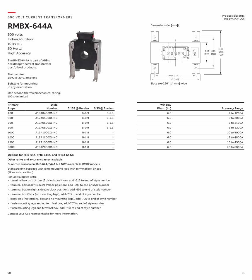
Product bulletin:1VAP701081-DB
600 volts Indoor/outdoor 10 kV BIL60 HertzHigh Accuracy
—6 0 0 VO LT CU R R ENT TR A NS FO R M ER S
RMBX-644A
Thermal rise:55°C @ 30°C ambient
Slots are 0.56" [14 mm] wide.Suitable for mounting in any orientation
Primary Amps
Style Number 0.15S @ Burden 0.3S @ Burden
Window Diam. (in.) Accuracy Range
400 A12A0400X1-NC B-0.9 B-1.8 6.0 4 to 1200A
500 A12A0500X1-NC B-0.9 B-1.8 6.0 5 to 2000A
600 A12A0600X1-NC B-0.9 B-1.8 6.0 6 to 2400A
800 A12A0800X1-NC B-0.9 B-1.8 6.0 8 to 3200A
1000 A12A1000X1-NC B-1.8 - 6.0 10 to 4000A
1200 A12A1200X1-NC B-1.8 - 6.0 12 to 4800A
1500 A12A1500X1-NC B-1.8 - 6.0 15 to 4500A
2000 A12A2000X1-NC B-1.8 - 6.0 20 to 6000A
One second thermal/mechanical rating: 100 x unlimited
Options for RMB-644, RMB-644A, and RMBX-644A:
Other ratios and accuracy classes available.
Dual-core available in RMB-644/644A but NOT available in RMBX models.
Standard unit supplied with long mounting legs with terminal box on top (12 o'clock position).
For unit supplied with:• terminal box on bottom (6 o'clock position), add -616 to end of style number
• terminal box on left side (9 o'clock position), add -698 to end of style number
• terminal box on right side (3 o'clock position), add -699 to end of style number
• terminal box ONLY (no mounting legs), add -705 to end of style number
• body only (no terminal box and no mounting legs), add -706 to end of style number
• flush mounting legs and no terminal box, add -707 to end of style number
• flush mounting legs and terminal box, add -708 to end of style number
Contact your ABB representative for more information.
Dimensions (in. [mm])
The RMBX-644A is part of ABB’s AccuRange® current transformer portfolio of products.
52 53
Primary Voltage
Style Number Ratio
IEEE MeteringAccuracy
Height (in.)
Width (in.)
Length (in.)
Weight (lbs.)
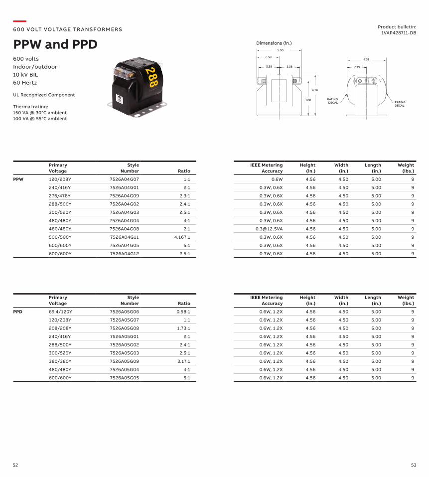
PPW 120/208Y 7526A04G07 1:1 0.6W 4.56 4.50 5.00 9
240/416Y 7526A04G01 2:1 0.3W, 0.6X 4.56 4.50 5.00 9
276/478Y 7526A04G09 2.3:1 0.3W, 0.6X 4.56 4.50 5.00 9
288/500Y 7526A04G02 2.4:1 0.3W, 0.6X 4.56 4.50 5.00 9
300/520Y 7526A04G03 2.5:1 0.3W, 0.6X 4.56 4.50 5.00 9
480/480Y 7526A04G04 4:1 0.3W, 0.6X 4.56 4.50 5.00 9
480/480Y 7526A04G08 2:1 [email protected] 4.56 4.50 5.00 9
500/500Y 7526A04G11 4.167:1 0.3W, 0.6X 4.56 4.50 5.00 9
600/600Y 7526A04G05 5:1 0.3W, 0.6X 4.56 4.50 5.00 9
600/600Y 7526A04G12 2.5:1 0.3W, 0.6X 4.56 4.50 5.00 9
3.88
4.56
2.282.28
2.50
5.00
4.38
2.19
RATING DECAL
RATING DECAL
Primary Voltage
Style Number Ratio
IEEE MeteringAccuracy
Height (in.)
Width (in.)
Length (in.)
Weight (lbs.)
PPD 69.4/120Y 7526A05G06 0.58:1 0.6W, 1.2X 4.56 4.50 5.00 9
120/208Y 7526A05G07 1:1 0.6W, 1.2X 4.56 4.50 5.00 9
208/208Y 7526A05G08 1.73:1 0.6W, 1.2X 4.56 4.50 5.00 9
240/416Y 7526A05G01 2:1 0.6W, 1.2X 4.56 4.50 5.00 9
288/500Y 7526A05G02 2.4:1 0.6W, 1.2X 4.56 4.50 5.00 9
300/520Y 7526A05G03 2.5:1 0.6W, 1.2X 4.56 4.50 5.00 9
380/380Y 7526A05G09 3.17:1 0.6W, 1.2X 4.56 4.50 5.00 9
480/480Y 7526A05G04 4:1 0.6W, 1.2X 4.56 4.50 5.00 9
600/600Y 7526A05G05 5:1 0.6W, 1.2X 4.56 4.50 5.00 9
—6 0 0 VOLT VOLTAG E TR A NS FOR M ER S
PPW and PPD600 volts Indoor/outdoor 10 kV BIL60 Hertz
UL Recognized Component
Product bulletin:1VAP428711-DB
Thermal rating:150 VA @ 30°C ambient100 VA @ 55°C ambient
Dimensions (in.)
54 55
PrimaryVoltage
StyleNumber Ratio
IEEE MeteringAccuracy
Height (in.)
Width (in.)
Length (in.)
Weight (lbs.)
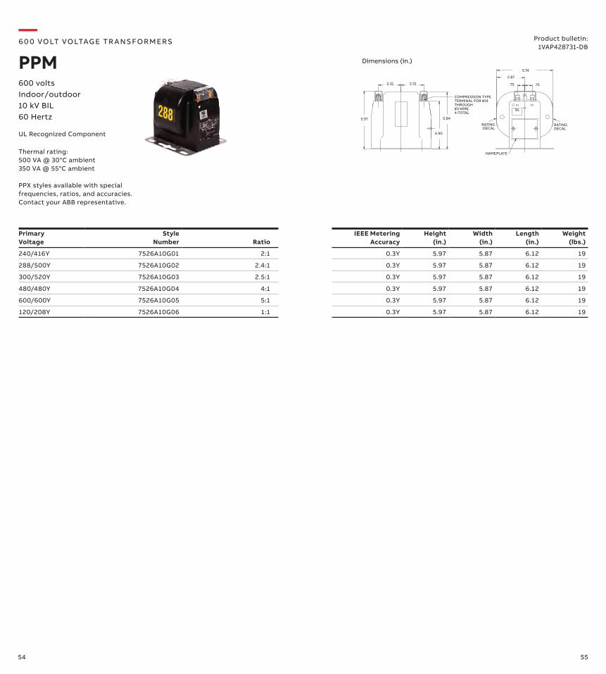
240/416Y 7526A10G01 2:1 0.3Y 5.97 5.87 6.12 19
288/500Y 7526A10G02 2.4:1 0.3Y 5.97 5.87 6.12 19
300/520Y 7526A10G03 2.5:1 0.3Y 5.97 5.87 6.12 19
480/480Y 7526A10G04 4:1 0.3Y 5.97 5.87 6.12 19
600/600Y 7526A10G05 5:1 0.3Y 5.97 5.87 6.12 19
120/208Y 7526A10G06 1:1 0.3Y 5.97 5.87 6.12 19
X1 X2LV
.75 .75
2.87
5.74
NAMEPLATE
RATINGDECAL
RATINGDECAL
4.90
5.84
2.31 2.31
5.97
COMPRESSION TYPE TERMINAL FOR #14THROUGH #3 WIRE4-TOTAL
—6 0 0 VOLT VOLTAG E TR A NS FOR M ER S
PPM600 volts Indoor/outdoor 10 kV BIL60 Hertz
UL Recognized Component
Product bulletin:1VAP428731-DB
Thermal rating:500 VA @ 30°C ambient350 VA @ 55°C ambient
PPX styles available with special frequencies, ratios, and accuracies. Contact your ABB representative.
Dimensions (in.)
56 57
Primary Amps
StyleNumber
IEEE MeteringAccuracy
RelayingAccuracy
Rating Factor
Height (in.)
Width (in.)
Length (in.)
Weight (lbs.)
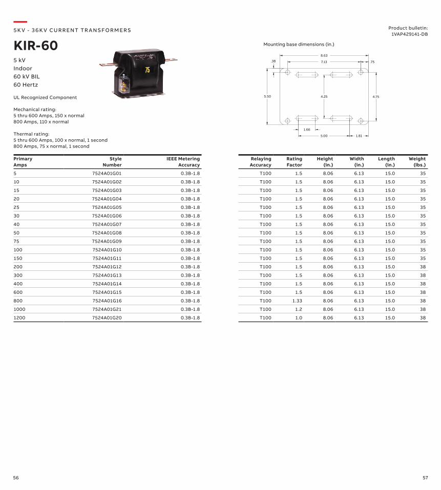
5 7524A01G01 0.3B-1.8 T100 1.5 8.06 6.13 15.0 35
10 7524A01G02 0.3B-1.8 T100 1.5 8.06 6.13 15.0 35
15 7524A01G03 0.3B-1.8 T100 1.5 8.06 6.13 15.0 35
20 7524A01G04 0.3B-1.8 T100 1.5 8.06 6.13 15.0 35
25 7524A01G05 0.3B-1.8 T100 1.5 8.06 6.13 15.0 35
30 7524A01G06 0.3B-1.8 T100 1.5 8.06 6.13 15.0 35
40 7524A01G07 0.3B-1.8 T100 1.5 8.06 6.13 15.0 35
50 7524A01G08 0.3B-1.8 T100 1.5 8.06 6.13 15.0 35
75 7524A01G09 0.3B-1.8 T100 1.5 8.06 6.13 15.0 35
100 7524A01G10 0.3B-1.8 T100 1.5 8.06 6.13 15.0 35
150 7524A01G11 0.3B-1.8 T100 1.5 8.06 6.13 15.0 35
200 7524A01G12 0.3B-1.8 T100 1.5 8.06 6.13 15.0 38
300 7524A01G13 0.3B-1.8 T100 1.5 8.06 6.13 15.0 38
400 7524A01G14 0.3B-1.8 T100 1.5 8.06 6.13 15.0 38
600 7524A01G15 0.3B-1.8 T100 1.5 8.06 6.13 15.0 38
800 7524A01G16 0.3B-1.8 T100 1.33 8.06 6.13 15.0 38
1000 7524A01G21 0.3B-1.8 T100 1.2 8.06 6.13 15.0 38
1200 7524A01G20 0.3B-1.8 T100 1.0 8.06 6.13 15.0 38
7.13
8.63
.75
4.75
.38
5.50
1.66
5.00 1.81
4.25
Mounting base dimensions (in.)
—5K V - 3 6 K V CU R R ENT TR A NS FO R M ER S
KIR-605 kVIndoor60 kV BIL60 Hertz
UL Recognized Component
Mechanical rating:5 thru 600 Amps, 150 x normal800 Amps, 110 x normal Thermal rating:5 thru 600 Amps, 100 x normal, 1 second800 Amps, 75 x normal, 1 second
Product bulletin:1VAP429141-DB
58 59
Primary Amps
StyleNumber
IEEE MeteringAccuracy
Window Diam. (in.)
Relaying Accuracy
Rating Factor @ 30°C
Height (in.)
Width (in.)
Length (in.)
Weight (lbs.)
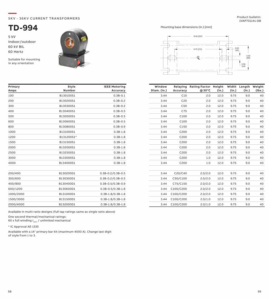
100 B130100S1 0.3B-0.1 3.44 C10 2.0 12.0 9.75 9.0 40
200 B130200S1 0.3B-0.2 3.44 C20 2.0 12.0 9.75 9.0 40
300 B130300S1 0.3B-0.2 3.44 C50 2.0 12.0 9.75 9.0 40
400 B130400S1 0.3B-0.5 3.44 C75 2.0 12.0 9.75 9.0 40
500 B130500S1 0.3B-0.5 3.44 C100 2.0 12.0 9.75 9.0 40
600 B130600S1 0.3B-0.5 3.44 C100 2.0 12.0 9.75 9.0 40
800 B130800S1 0.3B-0.9 3.44 C150 2.0 12.0 9.75 9.0 40
1000 B131000S1 0.3B-1.8 3.44 C200 2.0 12.0 9.75 9.0 40
1200 B131200S1* 0.3B-1.8 3.44 C200 2.0 12.0 9.75 9.0 40
1500 B131500S1 0.3B-1.8 3.44 C200 2.0 12.0 9.75 9.0 40
2000 B132000S1 0.3B-1.8 3.44 C200 2.0 12.0 9.75 9.0 40
2500 B132500S1 0.3B-1.8 3.44 C200 2.0 12.0 9.75 9.0 40
3000 B133000S1 0.3B-1.8 3.44 C200 1.0 12.0 9.75 9.0 40
4000 B134000S1 0.3B-1.8 3.44 C200 1.0 12.0 9.75 9.0 40
200/400 B130200D1 0.3B-0.2/0.3B-0.5 3.44 C20/C40 2.0/2.0 12.0 9.75 9.0 40
300/600 B130300D1 0.3B-0.2/0.3B-0.5 3.44 C50/C100 2.0/2.0 12.0 9.75 9.0 40
400/800 B130400D1 0.3B-0.5/0.3B-0.9 3.44 C75/C150 2.0/2.0 12.0 9.75 9.0 40
600/1200 B130600D1 0.3B-0.5/0.3B-1.8 3.44 C100/C200 2.0/2.0 12.0 9.75 9.0 40
1000/2000 B131000D1 0.3B-1.8/0.3B-1.8 3.44 C100/C200 2.0/2.0 12.0 9.75 9.0 40
1500/3000 B131500D1 0.3B-1.8/0.3B-1.8 3.44 C100/C200 2.0/1.0 12.0 9.75 9.0 40
2000/4000 B132000D1 0.3B-1.8/0.3B-1.8 3.44 C100/C200 2.0/1.0 12.0 9.75 9.0 40
6.75 [171] 0.63[16]
CL0.56[14]
8.56 [217]
3.50[89]
Suitable for mounting in any orientation
* IC Approval AE-1335
Available with a 14" primary bar kit (maximum 4000 A). Change last digit of style from 1 to 3.
Available in multi-ratio designs (full tap ratings same as single ratio above)
One second thermal/mechanical ratings: 60 x full winding Inom / unlimited mechanical
—5K V - 3 6 K V CU R R ENT TR A NS FO R M ER S
TD-9945 kVIndoor/outdoor60 kV BIL60 Hertz
Product bulletin:1VAP701141-DB
Mounting base dimensions (in.) [mm]
60 61
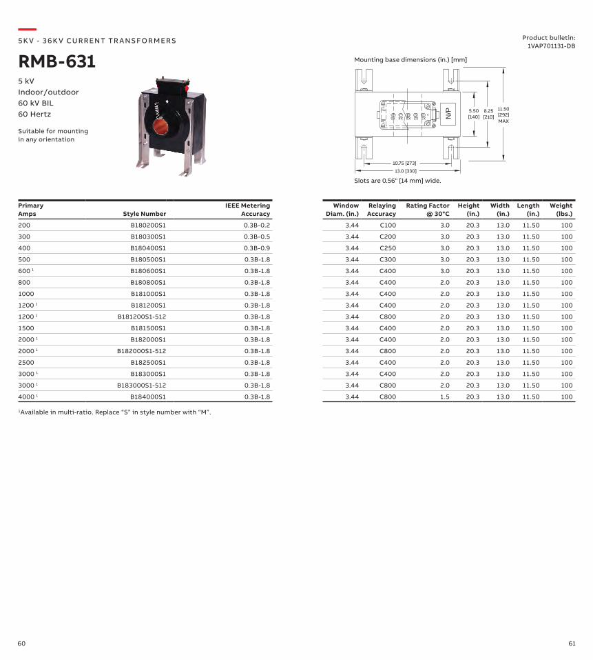
X2 X1X3X5 X4 N/P 8.25 11.505.50
10.75 [273]
13.0 [330]
[140] [210] [292]MAX
PrimaryAmps
Style Number
IEEE MeteringAccuracy
Window Diam. (in.)
Relaying Accuracy
Rating Factor @ 30°C
Height (in.)
Width (in.)
Length (in.)
Weight (lbs.)
200 B180200S1 0.3B-0.2 3.44 C100 3.0 20.3 13.0 11.50 100
300 B180300S1 0.3B-0.5 3.44 C200 3.0 20.3 13.0 11.50 100
400 B180400S1 0.3B-0.9 3.44 C250 3.0 20.3 13.0 11.50 100
500 B180500S1 0.3B-1.8 3.44 C300 3.0 20.3 13.0 11.50 100
600 1 B180600S1 0.3B-1.8 3.44 C400 3.0 20.3 13.0 11.50 100
800 B180800S1 0.3B-1.8 3.44 C400 2.0 20.3 13.0 11.50 100
1000 B181000S1 0.3B-1.8 3.44 C400 2.0 20.3 13.0 11.50 100
1200 1 B181200S1 0.3B-1.8 3.44 C400 2.0 20.3 13.0 11.50 100
1200 1 B181200S1-512 0.3B-1.8 3.44 C800 2.0 20.3 13.0 11.50 100
1500 B181500S1 0.3B-1.8 3.44 C400 2.0 20.3 13.0 11.50 100
2000 1 B182000S1 0.3B-1.8 3.44 C400 2.0 20.3 13.0 11.50 100
2000 1 B182000S1-512 0.3B-1.8 3.44 C800 2.0 20.3 13.0 11.50 100
2500 B182500S1 0.3B-1.8 3.44 C400 2.0 20.3 13.0 11.50 100
3000 1 B183000S1 0.3B-1.8 3.44 C400 2.0 20.3 13.0 11.50 100
3000 1 B183000S1-512 0.3B-1.8 3.44 C800 2.0 20.3 13.0 11.50 100
4000 1 B184000S1 0.3B-1.8 3.44 C800 1.5 20.3 13.0 11.50 100
—5K V - 3 6 K V CU R R ENT TR A NS FO R M ER S
RMB-631
Suitable for mounting in any orientation
5 kVIndoor/outdoor60 kV BIL60 Hertz
Product bulletin:1VAP701131-DB
Mounting base dimensions (in.) [mm]
Slots are 0.56" [14 mm] wide.
1Available in multi-ratio. Replace “S” in style number with “M”.
62 63
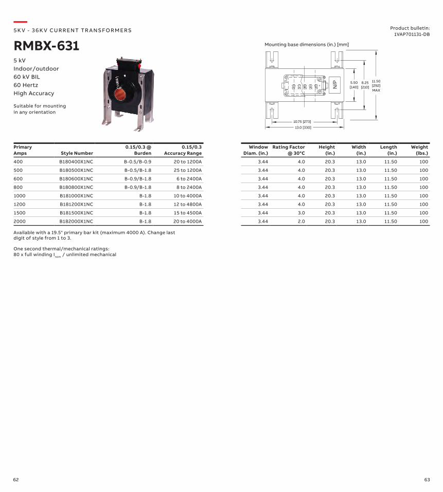
X2 X1X3X5 X4 N/P 8.25 11.505.50
10.75 [273]
13.0 [330]
[140] [210] [292]MAX
PrimaryAmps
Style Number
0.15/0.3 @ Burden
0.15/0.3 Accuracy Range
Window Diam. (in.)
Rating Factor @ 30°C
Height (in.)
Width (in.)
Length (in.)
Weight (lbs.)
400 B180400X1NC B-0.5/B-0.9 20 to 1200A 3.44 4.0 20.3 13.0 11.50 100
500 B180500X1NC B-0.5/B-1.8 25 to 1200A 3.44 4.0 20.3 13.0 11.50 100
600 B180600X1NC B-0.9/B-1.8 6 to 2400A 3.44 4.0 20.3 13.0 11.50 100
800 B180800X1NC B-0.9/B-1.8 8 to 2400A 3.44 4.0 20.3 13.0 11.50 100
1000 B181000X1NC B-1.8 10 to 4000A 3.44 4.0 20.3 13.0 11.50 100
1200 B181200X1NC B-1.8 12 to 4800A 3.44 4.0 20.3 13.0 11.50 100
1500 B181500X1NC B-1.8 15 to 4500A 3.44 3.0 20.3 13.0 11.50 100
2000 B182000X1NC B-1.8 20 to 4000A 3.44 2.0 20.3 13.0 11.50 100
Available with a 19.5" primary bar kit (maximum 4000 A). Change last digit of style from 1 to 3.
One second thermal/mechanical ratings: 80 x full winding Inom / unlimited mechanical
—5K V - 3 6 K V CU R R ENT TR A NS FO R M ER S
RMBX-631
Suitable for mounting in any orientation
5 kVIndoor/outdoor60 kV BIL60 HertzHigh Accuracy
Product bulletin:1VAP701131-DB
Mounting base dimensions (in.) [mm]
64 65
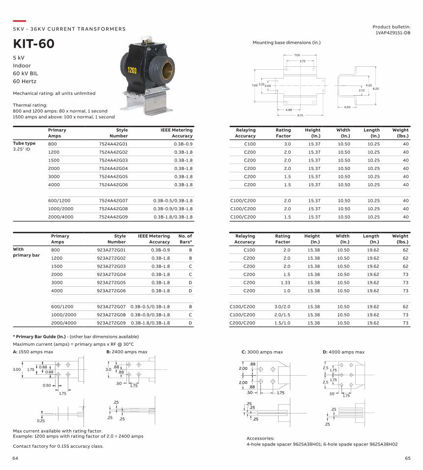
2.13
4.258.25
4.00
3.25
5.75
7.00
4.88
9.75
2.007.00
PrimaryAmps
Style Number
IEEE Metering Accuracy
Relaying Accuracy
Rating Factor
Height (in.)
Width (in.)
Length (in.)
Weight (lbs.)
Tube type3.25" ID
800 7524A42G01 0.3B-0.9 C100 3.0 15.37 10.50 10.25 40
1200 7524A42G02 0.3B-1.8 C200 2.0 15.37 10.50 10.25 40
1500 7524A42G03 0.3B-1.8 C200 2.0 15.37 10.50 10.25 40
2000 7524A42G04 0.3B-1.8 C200 2.0 15.37 10.50 10.25 40
3000 7524A42G05 0.3B-1.8 C200 1.5 15.37 10.50 10.25 40
4000 7524A42G06 0.3B-1.8 C200 1.5 15.37 10.50 10.25 40
600/1200 7524A42G07 0.3B-0.5/0.3B-1.8 C100/C200 2.0 15.37 10.50 10.25 40
1000/2000 7524A42G08 0.3B-0.9/0.3B-1.8 C100/C200 2.0 15.37 10.50 10.25 40
2000/4000 7524A42G09 0.3B-1.8/0.3B-1.8 C100/C200 1.5 15.37 10.50 10.25 40
Primary Amps
Style Number
IEEE Metering Accuracy
No. of Bars*
Relaying Accuracy
Rating Factor
Height (in.)
Width (in.)
Length (in.)
Weight (lbs.)
With primary bar
800 923A272G01 0.3B-0.9 B C100 2.0 15.38 10.50 19.62 62
1200 923A272G02 0.3B-1.8 B C200 2.0 15.38 10.50 19.62 62
1500 923A272G03 0.3B-1.8 C C200 2.0 15.38 10.50 19.62 62
2000 923A272G04 0.3B-1.8 C C200 1.5 15.38 10.50 19.62 73
3000 923A272G05 0.3B-1.8 D C200 1.33 15.38 10.50 19.62 73
4000 923A272G06 0.3B-1.8 D C200 1.0 15.38 10.50 19.62 73
600/1200 923A272G07 0.3B-0.5/0.3B-1.8 B C100/C200 3.0/2.0 15.38 10.50 19.62 62
1000/2000 923A272G08 0.3B-0.9/0.3B-1.8 C C100/C200 2.0/1.5 15.38 10.50 19.62 73
2000/4000 923A272G09 0.3B-1.8/0.3B-1.8 D C200/C200 1.5/1.0 15.38 10.50 19.62 73
Contact factory for 0.15S accuracy class.
B: 2400 amps max D: 4000 amps maxA: 1550 amps max
3.00 1.75 0.88
0.50
1.75
0.25
0.88
1.75.50
.88.883.0
.25.25
.25
1.75
1.75
2.5
2.5
.50 1.75
.25
.25.25
.25.25
.50 1.75.88
.882.00
2.00
C: 3000 amps max
Max current available with rating factor. Example: 1200 amps with rating factor of 2.0 = 2400 amps
—5K V - 3 6 K V CU R R ENT TR A NS FO R M ER S
KIT-605 kVIndoor60 kV BIL60 Hertz
Mechanical rating: all units unlimited
Product bulletin:1VAP429151-DB
* Primary Bar Guide (in.) - (other bar dimensions available)
Mounting base dimensions (in.)
Thermal rating:800 and 1200 amps: 80 x normal, 1 second1500 amps and above: 100 x normal, 1 second
Maximum current (amps) = primary amps x RF @ 30°C
Accessories:4-hole spade spacer 9625A38H01; 6-hole spade spacer 9625A38H02
66 67
Primary Amps
Style Number
IEEE Metering Accuracy
Relaying Accuracy
Rating Factor
Height (in.)
Width (in.)
Length (in.)
Weight (lbs.)
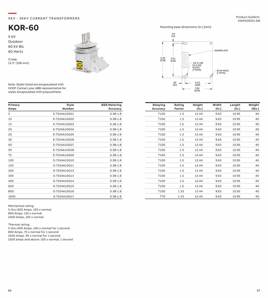
5 E-7524A10G01 0.3B-1.8 T100 1.5 12.44 9.63 10.95 40
10 E-7524A10G02 0.3B-1.8 T100 1.5 12.44 9.63 10.95 40
15 E-7524A10G03 0.3B-1.8 T100 1.5 12.44 9.63 10.95 40
20 E-7524A10G04 0.3B-1.8 T100 1.5 12.44 9.63 10.95 40
25 E-7524A10G05 0.3B-1.8 T100 1.5 12.44 9.63 10.95 40
30 E-7524A10G06 0.3B-1.8 T100 1.5 12.44 9.63 10.95 40
40 E-7524A10G07 0.3B-1.8 T100 1.5 12.44 9.63 10.95 40
50 E-7524A10G08 0.3B-1.8 T100 1.5 12.44 9.63 10.95 40
75 E-7524A10G09 0.3B-1.8 T100 1.5 12.44 9.63 10.95 40
100 E-7524A10G10 0.3B-1.8 T100 1.5 12.44 9.63 10.95 40
150 E-7524A10G11 0.3B-1.8 T100 1.5 12.44 9.63 10.95 40
200 E-7524A10G12 0.3B-1.8 T100 1.5 12.44 9.63 10.95 40
300 E-7524A10G13 0.3B-1.8 T100 1.5 12.44 9.63 10.95 40
400 E-7524A10G14 0.3B-1.8 T100 1.5 12.44 9.63 10.95 40
600 E-7524A10G15 0.3B-1.8 T100 1.5 12.44 9.63 10.95 40
800 E-7524A10G16 0.3B-1.8 T100 1.33 12.44 9.63 10.95 40
1000 E-7524A10G17 0.3B-1.8 T70 1.33 12.44 9.63 10.95 40
8.51[216]
9.39[238]
6.63[168]7.89
[200]
NAMEPLATE
.44 X 1.88[11 X 22] SLOTS2-TOTAL
.44[11]
.82 [21]
Ø.44 HOLE2-TOTAL
—5K V - 3 6 K V CU R R ENT TR A NS FO R M ER S
KOR-605 kVOutdoor60 kV BIL60 Hertz
Creep:13.3" (338 mm)
Product bulletin:1VAP429201-DB
Mechanical rating:5 thru 600 Amps, 150 x normal800 Amps, 110 x normal 1000 Amps, 150 x normal
Thermal rating:5 thru 600 Amps, 100 x normal for 1 second800 Amps, 75 x normal for 1 second1000 Amps, 50 x normal for 1 second1500 amps and above: 100 x normal, 1 second
Mounting base dimensions (in.) [mm]
Note: Styles listed are encapsulated with HCEP. Contact your ABB representative for styles encapsulated with polyurethane.
68 69
Primary Amps
Style Number
IEEE Metering Accuracy
Relaying Accuracy
Rating Factor
Height (in.)
Width (in.)
Length (in.)
Weight (lbs.)
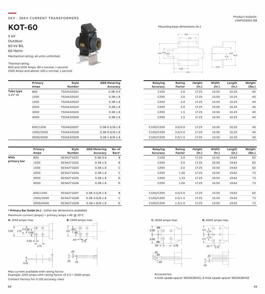
Tube type3.25" ID
800 7524A32G01 0.3B-0.9 C100 2.0 17.25 10.50 10.25 40
1200 7524A32G02 0.3B-1.8 C200 2.0 17.25 10.50 10.25 40
1500 7524A32G03 0.3B-1.8 C200 2.0 17.25 10.50 10.25 40
2000 7524A32G04 0.3B-1.8 C200 2.0 17.25 10.50 10.25 40
3000 7524A32G05 0.3B-1.8 C200 1.5 17.25 10.50 10.25 40
4000 7524A32G06 0.3B-1.8 C200 1.5 17.25 10.50 10.25 40
600/1200 7524A32G07 0.3B-0.5/B-1.8 C100/C200 3.0/2.0 17.25 10.50 10.25 40
1000/2000 7524A32G08 0.3B-0.9/B-1.8 C100/C200 3.0/2.0 17.25 10.50 10.25 40
2000/4000 7524A32G09 0.3B-1.8/B-1.8 C100/C200 2.0/1.5 17.25 10.50 10.25 40
Primary Amps
Style Number
IEEE Metering Accuracy
No. of Bars*
Relaying Accuracy
Rating Factor
Height (in.)
Width (in.)
Length (in.)
Weight (lbs.)
With primary bar
800 923A271G01 0.3B-0.9 B C100 2.0 17.25 10.50 19.62 62
1200 923A271G02 0.3B-1.8 B C200 2.0 17.25 10.50 19.62 62
1500 923A271G03 0.3B-1.8 C C200 2.0 17.25 10.50 19.62 62
2000 923A271G04 0.3B-1.8 C C200 1.50 17.25 10.50 19.62 73
3000 923A271G05 0.3B-1.8 D C200 1.33 17.25 10.50 19.62 73
4000 923A271G06 0.3B-1.8 D C200 1.00 17.25 10.50 19.62 73
600/1200 923A271G07 0.3B-0.5/B-1.8 B C100/C200 3.0/2.0 17.25 10.50 19.62 62
1000/2000 923A271G08 0.3B-0.9/B-1.8 C C100/C200 2.0/1.5 17.25 10.50 19.62 73
2000/4000 923A271G09 0.3B-1.8/B-1.8 D C100/C200 1.5/1.0 17.25 10.50 19.62 73
—5K V - 3 6 K V CU R R ENT TR A NS FO R M ER S
KOT-605 kVOutdoor60 kV BIL60 HertzMechanical rating: all units unlimited
Thermal rating:800 and 1200 Amps: 80 x normal, 1 second1500 Amps and above: 100 x normal, 1 second
Product bulletin:1VAP429301-DB
Mounting base dimensions (in.)
3.00 1.75 0.88
0.50
1.75
0.25
0.88
1.75.50
.88.883.0
.25.25
.25
1.75
1.75
2.5
2.5
.50 1.75
.25
.25.25
.25.25
.50 1.75.88
.882.00
2.00
* Primary Bar Guide (in.) - (other bar dimensions available)
Maximum current (amps) = primary amps x RF @ 30°C
Contact factory for 0.15S accuracy class
Max current available with rating factor. Example: 1200 amps with rating factor of 2.0 = 2400 amps Accessories:
4-hole spade spacer 9625A38H01; 6-hole spade spacer 9625A38H02
B: 2400 amps max D: 4000 amps maxA: 1550 amps max C: 3000 amps max
2.13
4.258.25
4.00
3.25
5.75
7.00
4.88
9.75
2.007.00
70 71
Primary Amps
Style Number
IEEE Metering Accuracy
Window Diam. (in.)
Relaying Accuracy
Rating Factor @ 30°C
Height (in.)
Width (in.)
Length (in.)
Weight (lbs.)
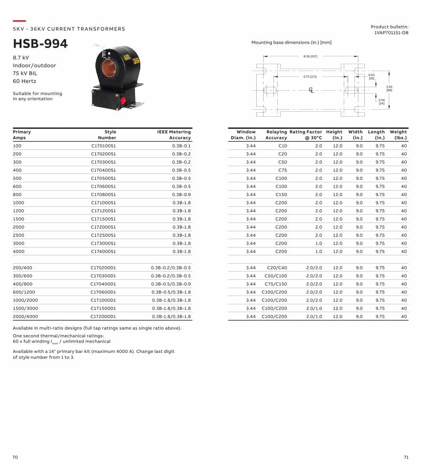
100 C170100S1 0.3B-0.1 3.44 C10 2.0 12.0 9.0 9.75 40
200 C170200S1 0.3B-0.2 3.44 C20 2.0 12.0 9.0 9.75 40
300 C170300S1 0.3B-0.2 3.44 C50 2.0 12.0 9.0 9.75 40
400 C170400S1 0.3B-0.5 3.44 C75 2.0 12.0 9.0 9.75 40
500 C170500S1 0.3B-0.5 3.44 C100 2.0 12.0 9.0 9.75 40
600 C170600S1 0.3B-0.5 3.44 C100 2.0 12.0 9.0 9.75 40
800 C170800S1 0.3B-0.9 3.44 C150 2.0 12.0 9.0 9.75 40
1000 C171000S1 0.3B-1.8 3.44 C200 2.0 12.0 9.0 9.75 40
1200 C171200S1 0.3B-1.8 3.44 C200 2.0 12.0 9.0 9.75 40
1500 C171500S1 0.3B-1.8 3.44 C200 2.0 12.0 9.0 9.75 40
2000 C172000S1 0.3B-1.8 3.44 C200 2.0 12.0 9.0 9.75 40
2500 C172500S1 0.3B-1.8 3.44 C200 2.0 12.0 9.0 9.75 40
3000 C173000S1 0.3B-1.8 3.44 C200 1.0 12.0 9.0 9.75 40
4000 C174000S1 0.3B-1.8 3.44 C200 1.0 12.0 9.0 9.75 40
200/400 C170200D1 0.3B-0.2/0.3B-0.5 3.44 C20/C40 2.0/2.0 12.0 9.0 9.75 40
300/600 C170300D1 0.3B-0.2/0.3B-0.5 3.44 C50/C100 2.0/2.0 12.0 9.0 9.75 40
400/800 C170400D1 0.3B-0.5/0.3B-0.9 3.44 C75/C150 2.0/2.0 12.0 9.0 9.75 40
600/1200 C170600D1 0.3B-0.5/0.3B-1.8 3.44 C100/C200 2.0/2.0 12.0 9.0 9.75 40
1000/2000 C171000D1 0.3B-1.8/0.3B-1.8 3.44 C100/C200 2.0/2.0 12.0 9.0 9.75 40
1500/3000 C171500D1 0.3B-1.8/0.3B-1.8 3.44 C100/C200 2.0/1.0 12.0 9.0 9.75 40
2000/4000 C172000D1 0.3B-1.8/0.3B-1.8 3.44 C100/C200 2.0/1.0 12.0 9.0 9.75 40
6.75 [171] 0.63[16]
CL0.56[14]
8.56 [217]
3.50[89]
Available with a 14" primary bar kit (maximum 4000 A). Change last digit of style number from 1 to 3.
Available in multi-ratio designs (full tap ratings same as single ratio above).
One second thermal/mechanical ratings: 60 x full winding Inom / unlimited mechanical
—5K V - 3 6 K V CU R R ENT TR A NS FO R M ER S
HSB-9948.7 kVIndoor/outdoor75 kV BIL60 Hertz
Suitable for mounting in any orientation
Product bulletin:1VAP701151-DB
Mounting base dimensions (in.) [mm]
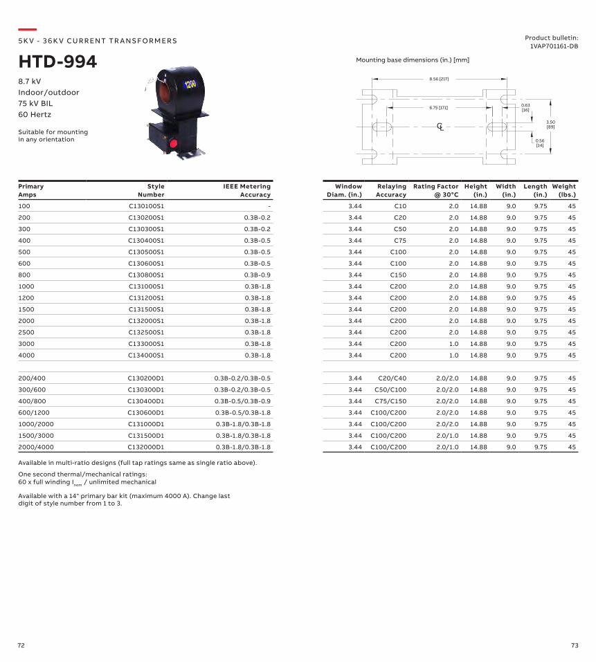
72 73
6.75 [171] 0.63[16]
CL0.56[14]
8.56 [217]
3.50[89]
PrimaryAmps
Style Number
IEEE MeteringAccuracy
Window Diam. (in.)
Relaying Accuracy
Rating Factor @ 30°C
Height (in.)
Width (in.)
Length (in.)
Weight (lbs.)
100 C130100S1 - 3.44 C10 2.0 14.88 9.0 9.75 45
200 C130200S1 0.3B-0.2 3.44 C20 2.0 14.88 9.0 9.75 45
300 C130300S1 0.3B-0.2 3.44 C50 2.0 14.88 9.0 9.75 45
400 C130400S1 0.3B-0.5 3.44 C75 2.0 14.88 9.0 9.75 45
500 C130500S1 0.3B-0.5 3.44 C100 2.0 14.88 9.0 9.75 45
600 C130600S1 0.3B-0.5 3.44 C100 2.0 14.88 9.0 9.75 45
800 C130800S1 0.3B-0.9 3.44 C150 2.0 14.88 9.0 9.75 45
1000 C131000S1 0.3B-1.8 3.44 C200 2.0 14.88 9.0 9.75 45
1200 C131200S1 0.3B-1.8 3.44 C200 2.0 14.88 9.0 9.75 45
1500 C131500S1 0.3B-1.8 3.44 C200 2.0 14.88 9.0 9.75 45
2000 C132000S1 0.3B-1.8 3.44 C200 2.0 14.88 9.0 9.75 45
2500 C132500S1 0.3B-1.8 3.44 C200 2.0 14.88 9.0 9.75 45
3000 C133000S1 0.3B-1.8 3.44 C200 1.0 14.88 9.0 9.75 45
4000 C134000S1 0.3B-1.8 3.44 C200 1.0 14.88 9.0 9.75 45
200/400 C130200D1 0.3B-0.2/0.3B-0.5 3.44 C20/C40 2.0/2.0 14.88 9.0 9.75 45
300/600 C130300D1 0.3B-0.2/0.3B-0.5 3.44 C50/C100 2.0/2.0 14.88 9.0 9.75 45
400/800 C130400D1 0.3B-0.5/0.3B-0.9 3.44 C75/C150 2.0/2.0 14.88 9.0 9.75 45
600/1200 C130600D1 0.3B-0.5/0.3B-1.8 3.44 C100/C200 2.0/2.0 14.88 9.0 9.75 45
1000/2000 C131000D1 0.3B-1.8/0.3B-1.8 3.44 C100/C200 2.0/2.0 14.88 9.0 9.75 45
1500/3000 C131500D1 0.3B-1.8/0.3B-1.8 3.44 C100/C200 2.0/1.0 14.88 9.0 9.75 45
2000/4000 C132000D1 0.3B-1.8/0.3B-1.8 3.44 C100/C200 2.0/1.0 14.88 9.0 9.75 45
Available with a 14" primary bar kit (maximum 4000 A). Change last digit of style number from 1 to 3.
Available in multi-ratio designs (full tap ratings same as single ratio above).
One second thermal/mechanical ratings: 60 x full winding Inom / unlimited mechanical
—5K V - 3 6 K V CU R R ENT TR A NS FO R M ER S
HTD-9948.7 kVIndoor/outdoor75 kV BIL60 Hertz
Product bulletin:1VAP701161-DB
Mounting base dimensions (in.) [mm]
Suitable for mounting in any orientation
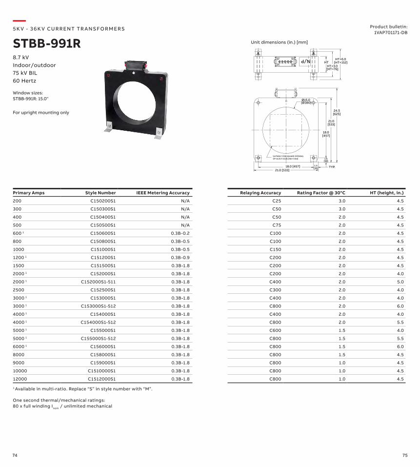
74 75
Primary Amps Style Number IEEE Metering Accuracy Relaying Accuracy Rating Factor @ 30°C HT (height, in.)
200 C150200S1 N/A C25 3.0 4.5
300 C150300S1 N/A C50 3.0 4.5
400 C150400S1 N/A C50 2.0 4.5
500 C150500S1 N/A C75 2.0 4.5
600 1 C150600S1 0.3B-0.2 C100 2.0 4.5
800 C150800S1 0.3B-0.5 C100 2.0 4.5
1000 C151000S1 0.3B-0.5 C150 2.0 4.5
1200 1 C151200S1 0.3B-0.9 C200 2.0 4.5
1500 C151500S1 0.3B-1.8 C200 2.0 4.5
2000 1 C152000S1 0.3B-1.8 C200 2.0 4.0
2000 1 C152000S1-511 0.3B-1.8 C400 2.0 5.0
2500 C152500S1 0.3B-1.8 C300 2.0 4.0
3000 1 C153000S1 0.3B-1.8 C400 2.0 4.0
3000 1 C153000S1-512 0.3B-1.8 C800 2.0 6.0
4000 1 C154000S1 0.3B-1.8 C400 2.0 4.0
4000 1 C154000S1-512 0.3B-1.8 C800 2.0 5.5
5000 1 C155000S1 0.3B-1.8 C600 1.5 4.0
5000 1 C155000S1-512 0.3B-1.8 C800 1.5 5.5
6000 1 C156000S1 0.3B-1.8 C800 1.5 6.0
8000 C158000S1 0.3B-1.8 C800 1.5 4.5
9000 C159000S1 0.3B-1.8 C800 1.0 4.5
10000 C1510000S1 0.3B-1.8 C800 1.0 4.5
12000 C1512000S1 0.3B-1.8 C800 1.0 4.5
—5K V - 3 6 K V CU R R ENT TR A NS FO R M ER S
STBB-991R8.7 kVIndoor/outdoor75 kV BIL60 Hertz
Product bulletin:1VAP701171-DB
For upright mounting only
HTHT+3.0
HT+6.0
18.0[457]
21.0[533]
21.0 [533]18.0 [457]
24.5[625]
1.5[38]
1.5[38]
TYP.
[HT+76]
[HT+152]
SUITABLE FOR SQUARE OPENINGOF 10.25 X 10.25 [260 X 260]
X1X5 X4 X3 X2
N/P
Ø15.0[Ø380]
1 Available in multi-ratio. Replace “S” in style number with “M”.
One second thermal/mechanical ratings: 80 x full winding Inom / unlimited mechanical
Unit dimensions (in.) [mm]
Window sizes:STBB-991R: 15.0"
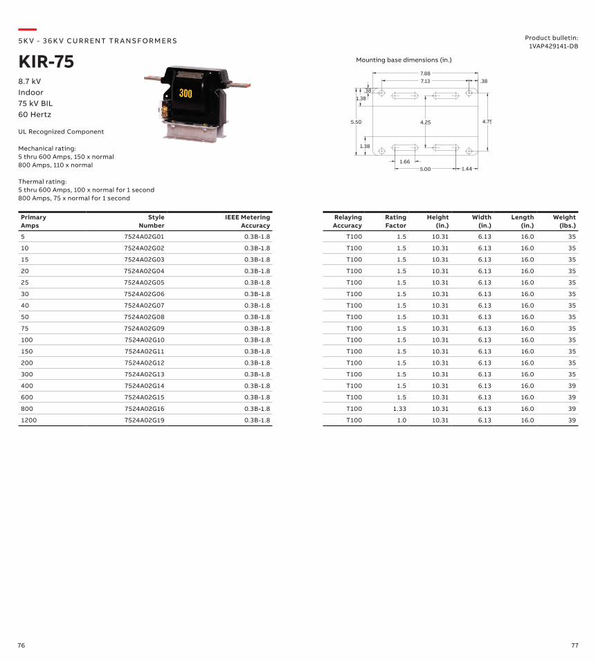
76 77
7.137.88
.38
4.75
.38
5.50
1.665.00 1.44
4.25
1.38
1.38
Primary Amps
Style Number
IEEE Metering Accuracy
RelayingAccuracy
Rating Factor
Height (in.)
Width (in.)
Length (in.)
Weight (lbs.)
5 7524A02G01 0.3B-1.8 T100 1.5 10.31 6.13 16.0 35
10 7524A02G02 0.3B-1.8 T100 1.5 10.31 6.13 16.0 35
15 7524A02G03 0.3B-1.8 T100 1.5 10.31 6.13 16.0 35
20 7524A02G04 0.3B-1.8 T100 1.5 10.31 6.13 16.0 35
25 7524A02G05 0.3B-1.8 T100 1.5 10.31 6.13 16.0 35
30 7524A02G06 0.3B-1.8 T100 1.5 10.31 6.13 16.0 35
40 7524A02G07 0.3B-1.8 T100 1.5 10.31 6.13 16.0 35
50 7524A02G08 0.3B-1.8 T100 1.5 10.31 6.13 16.0 35
75 7524A02G09 0.3B-1.8 T100 1.5 10.31 6.13 16.0 35
100 7524A02G10 0.3B-1.8 T100 1.5 10.31 6.13 16.0 35
150 7524A02G11 0.3B-1.8 T100 1.5 10.31 6.13 16.0 35
200 7524A02G12 0.3B-1.8 T100 1.5 10.31 6.13 16.0 35
300 7524A02G13 0.3B-1.8 T100 1.5 10.31 6.13 16.0 35
400 7524A02G14 0.3B-1.8 T100 1.5 10.31 6.13 16.0 39
600 7524A02G15 0.3B-1.8 T100 1.5 10.31 6.13 16.0 39
800 7524A02G16 0.3B-1.8 T100 1.33 10.31 6.13 16.0 39
1200 7524A02G19 0.3B-1.8 T100 1.0 10.31 6.13 16.0 39
—5K V - 3 6 K V CU R R ENT TR A NS FO R M ER S
KIR-758.7 kVIndoor75 kV BIL60 Hertz
Mechanical rating:5 thru 600 Amps, 150 x normal800 Amps, 110 x normal Thermal rating:5 thru 600 Amps, 100 x normal for 1 second800 Amps, 75 x normal for 1 second
Product bulletin:1VAP429141-DB
Mounting base dimensions (in.)
UL Recognized Component
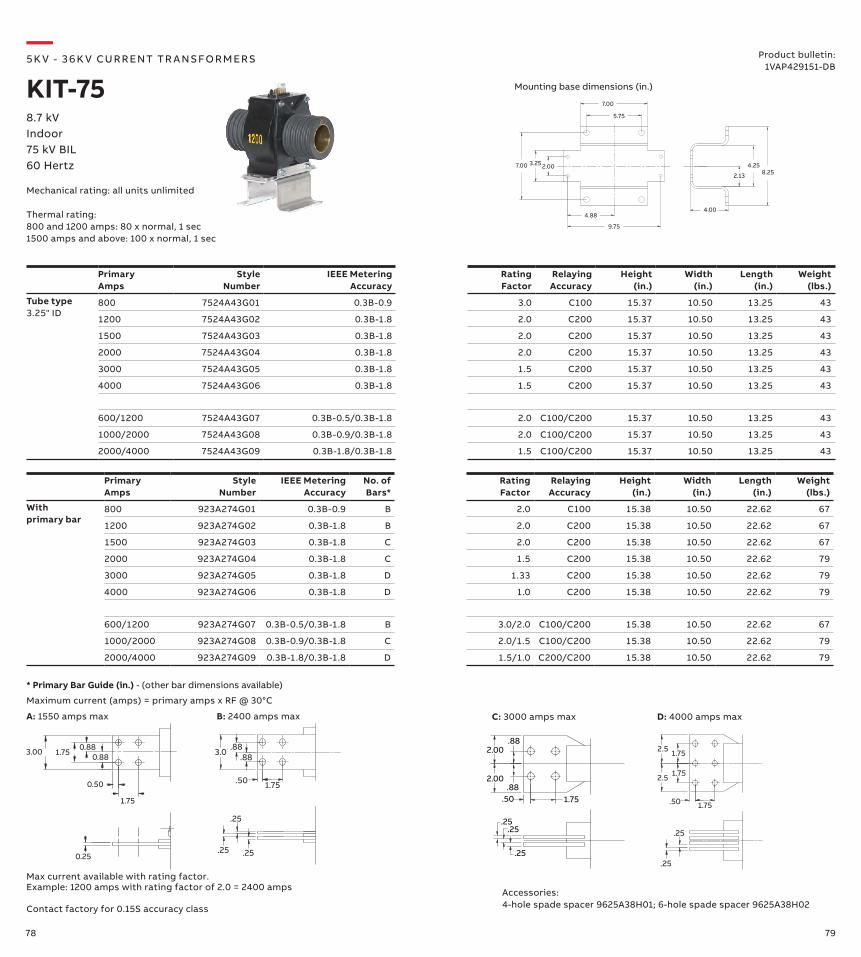
78 79
2.13
4.258.25
4.00
3.25
5.75
7.00
4.88
9.75
2.007.00
Primary Amps
Style Number
IEEE Metering Accuracy
Rating Factor
Relaying Accuracy
Height (in.)
Width (in.)
Length (in.)
Weight (lbs.)
Tube type3.25" ID
800 7524A43G01 0.3B-0.9 3.0 C100 15.37 10.50 13.25 43
1200 7524A43G02 0.3B-1.8 2.0 C200 15.37 10.50 13.25 43
1500 7524A43G03 0.3B-1.8 2.0 C200 15.37 10.50 13.25 43
2000 7524A43G04 0.3B-1.8 2.0 C200 15.37 10.50 13.25 43
3000 7524A43G05 0.3B-1.8 1.5 C200 15.37 10.50 13.25 43
4000 7524A43G06 0.3B-1.8 1.5 C200 15.37 10.50 13.25 43
600/1200 7524A43G07 0.3B-0.5/0.3B-1.8 2.0 C100/C200 15.37 10.50 13.25 43
1000/2000 7524A43G08 0.3B-0.9/0.3B-1.8 2.0 C100/C200 15.37 10.50 13.25 43
2000/4000 7524A43G09 0.3B-1.8/0.3B-1.8 1.5 C100/C200 15.37 10.50 13.25 43
Primary Amps
Style Number
IEEE Metering Accuracy
No. of Bars*
Rating Factor
Relaying Accuracy
Height (in.)
Width (in.)
Length (in.)
Weight (lbs.)
With primary bar
800 923A274G01 0.3B-0.9 B 2.0 C100 15.38 10.50 22.62 67
1200 923A274G02 0.3B-1.8 B 2.0 C200 15.38 10.50 22.62 67
1500 923A274G03 0.3B-1.8 C 2.0 C200 15.38 10.50 22.62 67
2000 923A274G04 0.3B-1.8 C 1.5 C200 15.38 10.50 22.62 79
3000 923A274G05 0.3B-1.8 D 1.33 C200 15.38 10.50 22.62 79
4000 923A274G06 0.3B-1.8 D 1.0 C200 15.38 10.50 22.62 79
600/1200 923A274G07 0.3B-0.5/0.3B-1.8 B 3.0/2.0 C100/C200 15.38 10.50 22.62 67
1000/2000 923A274G08 0.3B-0.9/0.3B-1.8 C 2.0/1.5 C100/C200 15.38 10.50 22.62 79
2000/4000 923A274G09 0.3B-1.8/0.3B-1.8 D 1.5/1.0 C200/C200 15.38 10.50 22.62 79
—5K V - 3 6 K V CU R R ENT TR A NS FO R M ER S
KIT-758.7 kVIndoor75 kV BIL60 Hertz
Mechanical rating: all units unlimited
Product bulletin:1VAP429151-DB
Mounting base dimensions (in.)
Thermal rating:800 and 1200 amps: 80 x normal, 1 sec1500 amps and above: 100 x normal, 1 sec
Contact factory for 0.15S accuracy class
3.00 1.75 0.88
0.50
1.75
0.25
0.88
1.75.50
.88.883.0
.25.25
.25
1.75
1.75
2.5
2.5
.50 1.75
.25
.25.25
.25.25
.50 1.75.88
.882.00
2.00
Max current available with rating factor. Example: 1200 amps with rating factor of 2.0 = 2400 amps
* Primary Bar Guide (in.) - (other bar dimensions available)
Maximum current (amps) = primary amps x RF @ 30°C
Accessories:4-hole spade spacer 9625A38H01; 6-hole spade spacer 9625A38H02
B: 2400 amps max D: 4000 amps maxA: 1550 amps max C: 3000 amps max
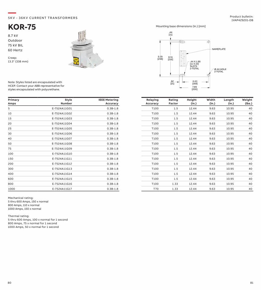
80 81
8.51[216]
9.39[238]
6.63[168]7.89
[200]
NAMEPLATE
.44 X 1.88[11 X 22] SLOTS2-TOTAL
.44[11]
.82 [21]
Ø.44 HOLE2-TOTAL
Primary Amps
Style Number
IEEE Metering Accuracy
Relaying Accuracy
Rating Factor
Height (in.)
Width (in.)
Length (in.)
Weight (lbs.)
5 E-7524A11G01 0.3B-1.8 T100 1.5 12.44 9.63 10.95 40
10 E-7524A11G02 0.3B-1.8 T100 1.5 12.44 9.63 10.95 40
15 E-7524A11G03 0.3B-1.8 T100 1.5 12.44 9.63 10.95 40
20 E-7524A11G04 0.3B-1.8 T100 1.5 12.44 9.63 10.95 40
25 E-7524A11G05 0.3B-1.8 T100 1.5 12.44 9.63 10.95 40
30 E-7524A11G06 0.3B-1.8 T100 1.5 12.44 9.63 10.95 40
40 E-7524A11G07 0.3B-1.8 T100 1.5 12.44 9.63 10.95 40
50 E-7524A11G08 0.3B-1.8 T100 1.5 12.44 9.63 10.95 40
75 E-7524A11G09 0.3B-1.8 T100 1.5 12.44 9.63 10.95 40
100 E-7524A11G10 0.3B-1.8 T100 1.5 12.44 9.63 10.95 40
150 E-7524A11G11 0.3B-1.8 T100 1.5 12.44 9.63 10.95 40
200 E-7524A11G12 0.3B-1.8 T100 1.5 12.44 9.63 10.95 40
300 E-7524A11G13 0.3B-1.8 T100 1.5 12.44 9.63 10.95 40
400 E-7524A11G14 0.3B-1.8 T100 1.5 12.44 9.63 10.95 40
600 E-7524A11G15 0.3B-1.8 T100 1.5 12.44 9.63 10.95 40
800 E-7524A11G16 0.3B-1.8 T100 1.33 12.44 9.63 10.95 40
1000 E-7524A11G17 0.3B-1.8 T70 1.33 12.44 9.63 10.95 40
—5K V - 3 6 K V CU R R ENT TR A NS FO R M ER S
KOR-758.7 kVOutdoor75 kV BIL60 Hertz
Creep:13.3" (338 mm)
Product bulletin:1VAP429201-DB
Mechanical rating:5 thru 600 Amps, 150 x normal800 Amps, 110 x normal 1000 Amps, 150 x normal
Thermal rating:5 thru 600 Amps, 100 x normal for 1 second800 Amps, 75 x normal for 1 second1000 Amps, 50 x normal for 1 second
Mounting base dimensions (in.) [mm]
Note: Styles listed are encapsulated with HCEP. Contact your ABB representative for styles encapsulated with polyurethane.
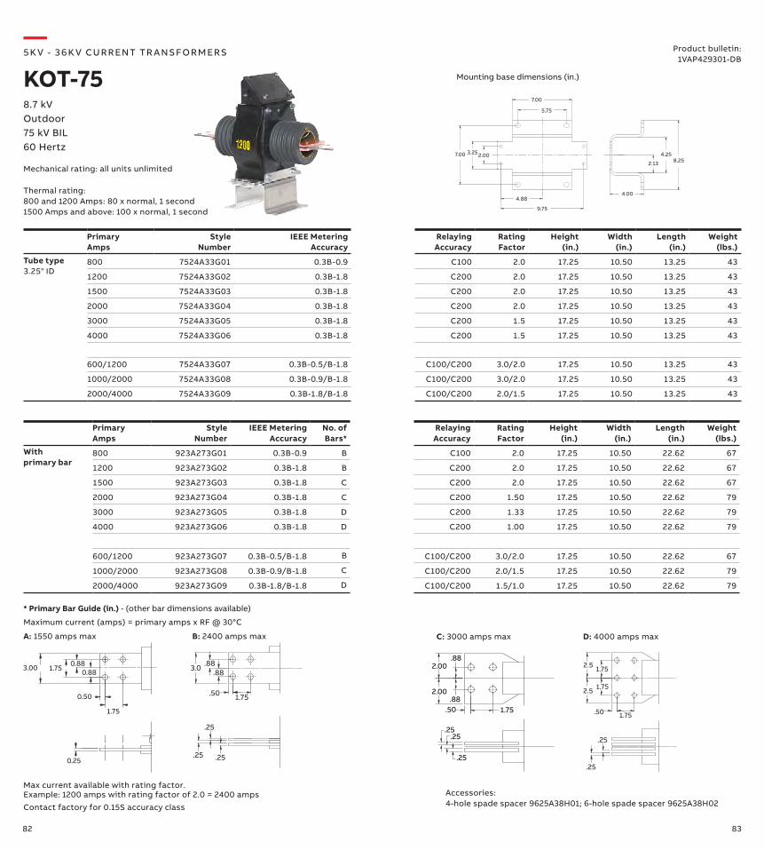
82 83
PrimaryAmps
StyleNumber
IEEE MeteringAccuracy
Relaying Accuracy
Rating Factor
Height (in.)
Width (in.)
Length (in.)
Weight (lbs.)
Tube type3.25" ID
800 7524A33G01 0.3B-0.9 C100 2.0 17.25 10.50 13.25 43
1200 7524A33G02 0.3B-1.8 C200 2.0 17.25 10.50 13.25 43
1500 7524A33G03 0.3B-1.8 C200 2.0 17.25 10.50 13.25 43
2000 7524A33G04 0.3B-1.8 C200 2.0 17.25 10.50 13.25 43
3000 7524A33G05 0.3B-1.8 C200 1.5 17.25 10.50 13.25 43
4000 7524A33G06 0.3B-1.8 C200 1.5 17.25 10.50 13.25 43
600/1200 7524A33G07 0.3B-0.5/B-1.8 C100/C200 3.0/2.0 17.25 10.50 13.25 43
1000/2000 7524A33G08 0.3B-0.9/B-1.8 C100/C200 3.0/2.0 17.25 10.50 13.25 43
2000/4000 7524A33G09 0.3B-1.8/B-1.8 C100/C200 2.0/1.5 17.25 10.50 13.25 43
Primary Amps
Style Number
IEEE Metering Accuracy
No. of Bars*
Relaying Accuracy
Rating Factor
Height (in.)
Width (in.)
Length (in.)
Weight (lbs.)
With primary bar
800 923A273G01 0.3B-0.9 B C100 2.0 17.25 10.50 22.62 67
1200 923A273G02 0.3B-1.8 B C200 2.0 17.25 10.50 22.62 67
1500 923A273G03 0.3B-1.8 C C200 2.0 17.25 10.50 22.62 67
2000 923A273G04 0.3B-1.8 C C200 1.50 17.25 10.50 22.62 79
3000 923A273G05 0.3B-1.8 D C200 1.33 17.25 10.50 22.62 79
4000 923A273G06 0.3B-1.8 D C200 1.00 17.25 10.50 22.62 79
600/1200 923A273G07 0.3B-0.5/B-1.8 B C100/C200 3.0/2.0 17.25 10.50 22.62 67
1000/2000 923A273G08 0.3B-0.9/B-1.8 C C100/C200 2.0/1.5 17.25 10.50 22.62 79
2000/4000 923A273G09 0.3B-1.8/B-1.8 D C100/C200 1.5/1.0 17.25 10.50 22.62 79
—5K V - 3 6 K V CU R R ENT TR A NS FO R M ER S
KOT-758.7 kVOutdoor75 kV BIL60 Hertz
Mechanical rating: all units unlimited
Product bulletin:1VAP429301-DB
Mounting base dimensions (in.)
Thermal rating:800 and 1200 Amps: 80 x normal, 1 second1500 Amps and above: 100 x normal, 1 second
3.00 1.75 0.88
0.50
1.75
0.25
0.88
1.75.50
.88.883.0
.25.25
.25
1.75
1.75
2.5
2.5
.50 1.75
.25
.25.25
.25.25
.50 1.75.88
.882.00
2.00
* Primary Bar Guide (in.) - (other bar dimensions available)
Maximum current (amps) = primary amps x RF @ 30°C
Contact factory for 0.15S accuracy class
Max current available with rating factor. Example: 1200 amps with rating factor of 2.0 = 2400 amps Accessories:
4-hole spade spacer 9625A38H01; 6-hole spade spacer 9625A38H02
B: 2400 amps max D: 4000 amps maxA: 1550 amps max C: 3000 amps max
2.13
4.258.25
4.00
3.25
5.75
7.00
4.88
9.75
2.007.00
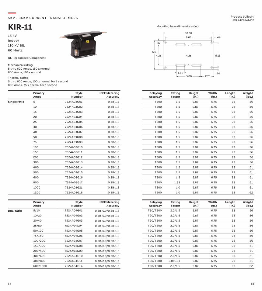
84 85
Primary Amps
Style Number
IEEE Metering Accuracy
RelayingAccuracy
Rating Factor
Height (in.)
Width (in.)
Length (in.)
Weight (lbs.)
Dual ratio 5/10 7524A04G01 0.3B-0.9/0.3B-1.8 T90/T200 2.0/1.5 9.87 6.75 23 56
10/20 7524A04G02 0.3B-0.9/0.3B-1.8 T90/T200 2.0/1.5 9.87 6.75 23 56
20/40 7524A04G03 0.3B-0.9/0.3B-1.8 T90/T200 2.0/1.5 9.87 6.75 23 56
25/50 7524A04G04 0.3B-0.9/0.3B-1.8 T90/T200 2.0/1.5 9.87 6.75 23 56
50/100 7524A04G05 0.3B-0.9/0.3B-1.8 T90/T200 2.0/1.5 9.87 6.75 23 56
75/150 7524A04G06 0.3B-0.9/0.3B-1.8 T90/T200 2.0/1.5 9.87 6.75 23 56
100/200 7524A04G07 0.3B-0.9/0.3B-1.8 T90/T200 2.0/1.5 9.87 6.75 23 56
150/300 7524A04G08 0.3B-0.9/0.3B-1.8 T90/T200 2.0/1.5 9.87 6.75 23 61
200/400 7524A04G09 0.3B-0.9/0.3B-1.8 T90/T200 2.0/1.5 9.87 6.75 23 61
300/600 7524A04G10 0.3B-0.9/0.3B-1.8 T90/T200 2.0/1.5 9.87 6.75 23 61
400/800 7524A04G11 0.3B-0.9/0.3B-1.8 T100/T200 2.0/1.33 9.87 6.75 23 61
600/1200 7524A04G14 0.3B-0.9/0.3B-1.8 T90/T200 2.0/1.5 9.87 6.75 23 62
Primary Amps
Style Number
IEEE Metering Accuracy
RelayingAccuracy
Rating Factor
Height (in.)
Width (in.)
Length (in.)
Weight (lbs.)
Single ratio 5 7524A03G01 0.3B-1.8 T200 1.5 9.87 6.75 23 56
10 7524A03G02 0.3B-1.8 T200 1.5 9.87 6.75 23 56
15 7524A03G03 0.3B-1.8 T200 1.5 9.87 6.75 23 56
20 7524A03G04 0.3B-1.8 T200 1.5 9.87 6.75 23 56
25 7524A03G05 0.3B-1.8 T200 1.5 9.87 6.75 23 56
30 7524A03G06 0.3B-1.8 T200 1.5 9.87 6.75 23 56
40 7524A03G07 0.3B-1.8 T200 1.5 9.87 6.75 23 56
50 7524A03G08 0.3B-1.8 T200 1.5 9.87 6.75 23 56
75 7524A03G09 0.3B-1.8 T200 1.5 9.87 6.75 23 56
100 7524A03G10 0.3B-1.8 T200 1.5 9.87 6.75 23 56
150 7524A03G11 0.3B-1.8 T200 1.5 9.87 6.75 23 56
200 7524A03G12 0.3B-1.8 T200 1.5 9.87 6.75 23 56
300 7524A03G13 0.3B-1.8 T200 1.5 9.87 6.75 23 56
400 7524A03G14 0.3B-1.8 T200 1.5 9.87 6.75 23 61
500 7524A03G15 0.3B-1.8 T200 1.5 9.87 6.75 23 61
600 7524A03G16 0.3B-1.8 T200 1.5 9.87 6.75 23 61
800 7524A03G17 0.3B-1.8 T200 1.33 9.87 6.75 23 61
1000 7524A03G21 0.3B-1.8 T200 1.0 9.87 6.75 23 61
1200 7524A03G18 0.3B-1.8 T200 1.0 9.87 6.75 23 62
9.63 .4410.50
5.13
.442.75
1.665.00
.87
4.256.0
4.25
—5K V - 3 6 K V CU R R ENT TR A NS FO R M ER S
KIR-1115 kVIndoor110 kV BIL60 Hertz
Mechanical rating:5 thru 600 Amps, 150 x normal800 Amps, 110 x normal
Thermal rating:5 thru 600 Amps, 100 x normal for 1 second800 Amps, 75 x normal for 1 second
Product bulletin:1VAP429141-DB
Mounting base dimensions (in.)
UL Recognized Component
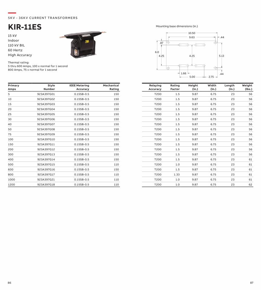
86 87
Primary Amps
Style Number
IEEE Metering Accuracy
Mechanical Rating
Relaying Accuracy
Rating Factor
Height (in.)
Width (in.)
Length (in.)
Weight (lbs.)
5 923A397G01 0.15SB-0.5 150 T200 1.5 9.87 6.75 23 56
10 923A397G02 0.15SB-0.5 150 T200 1.5 9.87 6.75 23 56
15 923A397G03 0.15SB-0.5 150 T200 1.5 9.87 6.75 23 56
20 923A397G04 0.15SB-0.5 150 T200 1.5 9.87 6.75 23 56
25 923A397G05 0.15SB-0.5 150 T200 1.5 9.87 6.75 23 56
30 923A397G06 0.15SB-0.5 150 T200 1.5 9.87 6.75 23 56
40 923A397G07 0.15SB-0.5 150 T200 1.5 9.87 6.75 23 56
50 923A397G08 0.15SB-0.5 150 T200 1.5 9.87 6.75 23 56
75 923A397G09 0.15SB-0.5 150 T200 1.5 9.87 6.75 23 56
100 923A397G10 0.15SB-0.5 150 T200 1.5 9.87 6.75 23 56
150 923A397G11 0.15SB-0.5 150 T200 1.5 9.87 6.75 23 56
200 923A397G12 0.15SB-0.5 150 T200 1.5 9.87 6.75 23 56
300 923A397G13 0.15SB-0.5 150 T200 1.5 9.87 6.75 23 56
400 923A397G14 0.15SB-0.5 150 T200 1.5 9.87 6.75 23 61
500 923A397G15 0.15SB-0.5 110 T200 1.0 9.87 6.75 23 61
600 923A397G16 0.15SB-0.5 150 T200 1.5 9.87 6.75 23 61
800 923A397G17 0.15SB-0.5 110 T200 1.33 9.87 6.75 23 61
1000 923A397G21 0.15SB-0.5 110 T200 1.0 9.87 6.75 23 61
1200 923A397G18 0.15SB-0.5 110 T200 1.0 9.87 6.75 23 62
9.63 .4410.50
5.13
.442.75
1.665.00
.87
4.256.0
4.25
—5K V - 3 6 K V CU R R ENT TR A NS FO R M ER S
KIR-11ES15 kVIndoor110 kV BIL60 HertzHigh Accuracy
Thermal rating:5 thru 600 Amps, 100 x normal for 1 second800 Amps, 75 x normal for 1 second
Mounting base dimensions (in.)
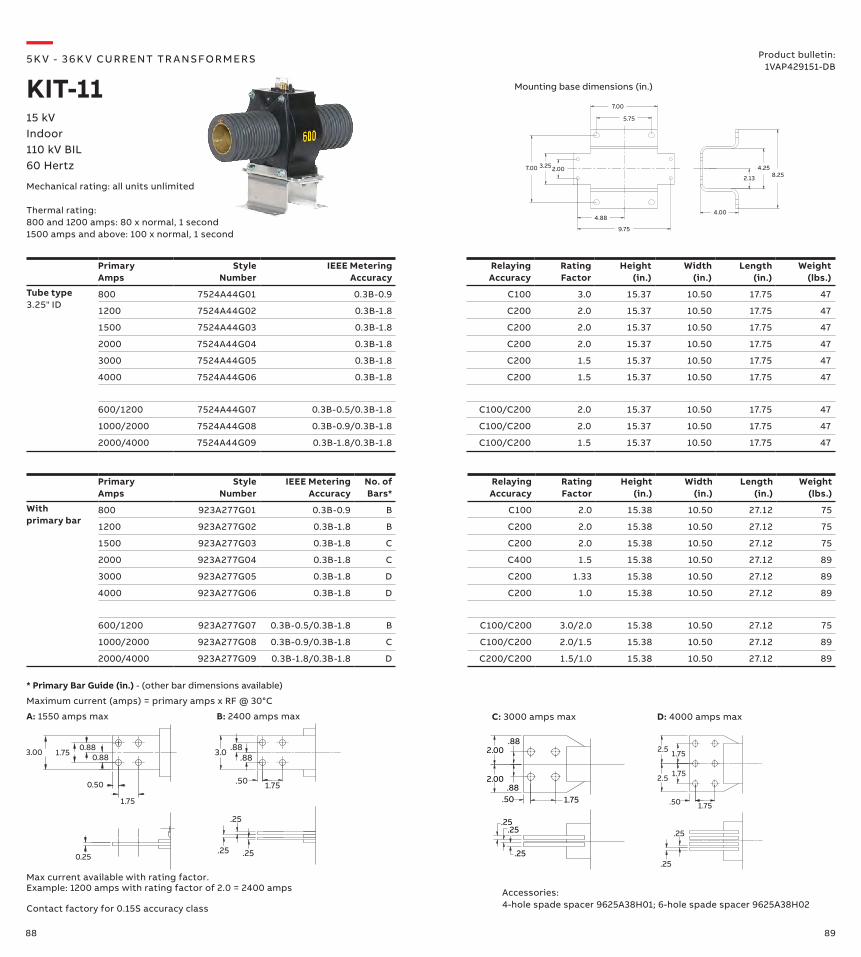
88 89
2.13
4.258.25
4.00
3.25
5.75
7.00
4.88
9.75
2.007.00
PrimaryAmps
Style Number
IEEE Metering Accuracy
Relaying Accuracy
Rating Factor
Height (in.)
Width (in.)
Length (in.)
Weight (lbs.)
Tube type3.25" ID
800 7524A44G01 0.3B-0.9 C100 3.0 15.37 10.50 17.75 47
1200 7524A44G02 0.3B-1.8 C200 2.0 15.37 10.50 17.75 47
1500 7524A44G03 0.3B-1.8 C200 2.0 15.37 10.50 17.75 47
2000 7524A44G04 0.3B-1.8 C200 2.0 15.37 10.50 17.75 47
3000 7524A44G05 0.3B-1.8 C200 1.5 15.37 10.50 17.75 47
4000 7524A44G06 0.3B-1.8 C200 1.5 15.37 10.50 17.75 47
600/1200 7524A44G07 0.3B-0.5/0.3B-1.8 C100/C200 2.0 15.37 10.50 17.75 47
1000/2000 7524A44G08 0.3B-0.9/0.3B-1.8 C100/C200 2.0 15.37 10.50 17.75 47
2000/4000 7524A44G09 0.3B-1.8/0.3B-1.8 C100/C200 1.5 15.37 10.50 17.75 47
PrimaryAmps
Style Number
IEEE Metering Accuracy
No. of Bars*
Relaying Accuracy
Rating Factor
Height (in.)
Width (in.)
Length (in.)
Weight (lbs.)
With primary bar
800 923A277G01 0.3B-0.9 B C100 2.0 15.38 10.50 27.12 75
1200 923A277G02 0.3B-1.8 B C200 2.0 15.38 10.50 27.12 75
1500 923A277G03 0.3B-1.8 C C200 2.0 15.38 10.50 27.12 75
2000 923A277G04 0.3B-1.8 C C400 1.5 15.38 10.50 27.12 89
3000 923A277G05 0.3B-1.8 D C200 1.33 15.38 10.50 27.12 89
4000 923A277G06 0.3B-1.8 D C200 1.0 15.38 10.50 27.12 89
600/1200 923A277G07 0.3B-0.5/0.3B-1.8 B C100/C200 3.0/2.0 15.38 10.50 27.12 75
1000/2000 923A277G08 0.3B-0.9/0.3B-1.8 C C100/C200 2.0/1.5 15.38 10.50 27.12 89
2000/4000 923A277G09 0.3B-1.8/0.3B-1.8 D C200/C200 1.5/1.0 15.38 10.50 27.12 89
—5K V - 3 6 K V CU R R ENT TR A NS FO R M ER S
KIT-1115 kVIndoor110 kV BIL60 Hertz
Mechanical rating: all units unlimited
Thermal rating:800 and 1200 amps: 80 x normal, 1 second1500 amps and above: 100 x normal, 1 second
Product bulletin:1VAP429151-DB
Mounting base dimensions (in.)
Contact factory for 0.15S accuracy class
3.00 1.75 0.88
0.50
1.75
0.25
0.88
1.75.50
.88.883.0
.25.25
.25
1.75
1.75
2.5
2.5
.50 1.75
.25
.25.25
.25.25
.50 1.75.88
.882.00
2.00
Max current available with rating factor. Example: 1200 amps with rating factor of 2.0 = 2400 amps
* Primary Bar Guide (in.) - (other bar dimensions available)
Maximum current (amps) = primary amps x RF @ 30°C
Accessories:4-hole spade spacer 9625A38H01; 6-hole spade spacer 9625A38H02
B: 2400 amps max D: 4000 amps maxA: 1550 amps max C: 3000 amps max
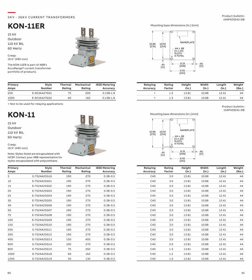
90 91
Primary Amps
Style Number
Thermal Rating
Mechanical Rating
IEEE Metering Accuracy
Relaying Accuracy
Rating Factor
Height (in.)
Width (in.)
Length (in.)
Weight (lbs.)
200 E-923A427G01 75 200 0.15B-1.8 + 1.5 13.81 10.88 12.41 44
1000 E-923A427G02 60 162 0.15B-1.8 + 1.5 13.81 10.88 12.41 44
10.88 [276]
10.00 [254]
.44[11]
8.19[208]
9.50[241]
.66 [17]
.44 x .88[11 x 22]SLOTS4-TOTAL
NAMEPLATE
10.88 [276]
10.00 [254]
.44[11]
8.19[208]
9.50[241]
.66 [17]
.44 x .88[11 x 22]SLOTS4-TOTAL
NAMEPLATE
+ Not to be used for relaying applications
Primary Amps
Style Number
Thermal Rating
Mechanical Rating
IEEE Metering Accuracy
Relaying Accuracy
Rating Factor
Height (in.)
Width (in.)
Length (in.)
Weight (lbs.)
5 E-7524A25G16 190 270 0.3B-0.5 C40 3.0 13.81 10.88 12.41 44
10 E-7524A25G01 190 270 0.3B-0.5 C40 3.0 13.81 10.88 12.41 44
15 E-7524A25G02 190 270 0.3B-0.5 C40 3.0 13.81 10.88 12.41 44
20 E-7524A25G03 190 270 0.3B-0.5 C40 3.0 13.81 10.88 12.41 44
25 E-7524A25G04 190 270 0.3B-0.5 C40 3.0 13.81 10.88 12.41 44
30 E-7524A25G05 190 270 0.3B-0.5 C40 3.0 13.81 10.88 12.41 44
40 E-7524A25G06 190 270 0.3B-0.5 C40 3.0 13.81 10.88 12.41 44
50 E-7524A25G07 190 270 0.3B-0.5 C40 3.0 13.81 10.88 12.41 44
75 E-7524A25G08 190 270 0.3B-0.5 C40 3.0 13.81 10.88 12.41 44
100 E-7524A25G09 190 270 0.3B-0.5 C40 3.0 13.81 10.88 12.41 44
150 E-7524A25G10 190 270 0.3B-0.5 C40 3.0 13.81 10.88 12.41 44
200 E-7524A25G11 190 270 0.3B-0.5 C40 3.0 13.81 10.88 12.41 44
300 E-7524A25G12 190 270 0.3B-0.5 C40 3.0 13.81 10.88 12.41 44
400 E-7524A25G13 150 405 0.3B-0.5 C40 3.0 13.81 10.88 12.41 44
600 E-7524A25G14 100 270 0.3B-0.5 C40 2.0 13.81 10.88 12.41 44
800 E-7524A25G15 75 202 0.3B-0.5 C40 1.5 13.81 10.88 12.41 44
1000 E-7524A25G18 60 162 0.3B-0.5 C40 1.2 13.81 10.88 12.41 44
1200 E-7524A25G19 50 135 0.3B-0.5 C40 1.0 13.81 10.88 12.41 44
KON-11
—5K V - 3 6 K V CU R R ENT TR A NS FO R M ER S
KON-11ER15 kVOutdoor110 kV BIL60 Hertz
Product bulletin:1VAP429242-DB
15 kVOutdoor110 kV BIL60 Hertz
Product bulletin:1VAP429241-DB
The KON-11ER is part of ABB’s AccuRange® current transformer portfolio of products.
Creep:19.5" (495 mm)
Mounting base dimensions (in.) [mm]
Mounting base dimensions (in.) [mm]
Note: Styles listed are encapsulated with HCEP. Contact your ABB representative for styles encapsulated with polyurethane.
Creep:19.5" (495 mm)

92 93
Primary Amps
Style Number
IEEE Metering Accuracy
Relaying Accuracy
Rating Factor
Height (in.)
Width (in.)
Length (in.)
Weight (lbs.)
Dual ratio 5/10 E-7524A13G01 0.3B-0.9/0.3B-1.8 T90/T200 2.0/1.5 15.75 11.0 12.48 67
10/20 E-7524A13G02 0.3B-0.9/0.3B-1.8 T90/T200 2.0/1.5 15.75 11.0 12.48 67
20/40 E-7524A13G03 0.3B-0.9/0.3B-1.8 T90/T200 2.0/1.5 15.75 11.0 12.48 67
25/50 E-7524A13G04 0.3B-0.9/0.3B-1.8 T90/T200 2.0/1.5 15.75 11.0 12.48 67
50/100 E-7524A13G05 0.3B-0.9/0.3B-1.8 T90/T200 2.0/1.5 15.75 11.0 12.48 67
75/150 E-7524A13G06 0.3B-0.9/0.3B-1.8 T90/T200 2.0/1.5 15.75 11.0 12.48 67
100/200 E-7524A13G07 0.3B-0.9/0.3B-1.8 T90/T200 2.0/1.5 15.75 11.0 12.48 67
150/300 E-7524A13G08 0.3B-0.9/0.3B-1.8 T90/T200 2.0/1.5 15.75 11.0 12.48 67
200/400 E-7524A13G09 0.3B-0.9/0.3B-1.8 T90/T200 2.0/1.5 15.75 11.0 12.48 67
300/600 E-7524A13G10 0.3B-0.9/0.3B-1.8 T90/T200 2.0/1.5 15.75 11.0 12.48 67
400/800 E-7524A13G11 0.3B-0.9/0.3B-1.8 T100/T200 2.0/1.5 15.75 11.0 12.48 67
600/1200 E-7524A13G12 0.3B-0.9/0.3B-1.8 T90/T200 2.0/1.5 15.75 11.0 12.48 67
PrimaryAmps
Style Number
IEEE Metering Accuracy
Relaying Accuracy
Rating Factor
Height (in.)
Width (in.)
Length (in.)
Weight (lbs.)
Single ratio 5 E-7524A12G01 0.3B-1.8 T200 1.5 15.75 11.0 12.48 67
10 E-7524A12G02 0.3B-1.8 T200 1.5 15.75 11.0 12.48 67
15 E-7524A12G03 0.3B-1.8 T200 1.5 15.75 11.0 12.48 67
20 E-7524A12G04 0.3B-1.8 T200 1.5 15.75 11.0 12.48 67
25 E-7524A12G05 0.3B-1.8 T200 1.5 15.75 11.0 12.48 67
30 E-7524A12G06 0.3B-1.8 T200 1.5 15.75 11.0 12.48 67
40 E-7524A12G07 0.3B-1.8 T200 1.5 15.75 11.0 12.48 67
50 E-7524A12G08 0.3B-1.8 T200 1.5 15.75 11.0 12.48 67
75 E-7524A12G09 0.3B-1.8 T200 1.5 15.75 11.0 12.48 67
100 E-7524A12G10 0.3B-1.8 T200 1.5 15.75 11.0 12.48 67
150 E-7524A12G11 0.3B-1.8 T200 1.5 15.75 11.0 12.48 67
200 E-7524A12G12 0.3B-1.8 T200 1.5 15.75 11.0 12.48 67
300 E-7524A12G13 0.3B-1.8 T200 1.5 15.75 11.0 12.48 67
400 E-7524A12G14 0.3B-1.8 T200 1.5 15.75 11.0 12.48 67
600 E-7524A12G15 0.3B-1.8 T200 1.5 15.75 11.0 12.48 67
800 E-7524A12G16 0.3B-1.8 T200 1.33 15.75 11.0 12.48 67
1000 E-7524A12G18 0.3B-1.8 T150 1.5 15.75 11.0 12.48 67
1200 E-7524A12G17 0.3B-1.8 T200 1.5 15.75 11.0 12.48 67
10.86[276]
9.98[253]
.44[11]
8.18[208]
9.48[241]
.66[17]
NAMEPLATE
.44 X .88[11 X 22]SLOTS4-TOTAL
—5K V - 3 6 K V CU R R ENT TR A NS FO R M ER S
KOR-1115 kVOutdoor110 kV BIL60 Hertz
Product bulletin:1VAP429221-DB
Creep: 20.8" (528 mm)
Mounting base dimensions (in.) [mm]
Note: Styles listed are encapsulated with HCEP. Contact your ABB representative for styles encapsulated with polyurethane.
Mechanical Rating:5 thru 600 Amps, 150 x normal800 Amps, 110 x normal1000 Amps, 180 x normal1200 Amps, 150 x normal
Thermal Rating:5 thru 600 Amps and 1200 amps, 100 x normal for 1 second; 800 Amps, 75 x normal for 1 second; 1000 amps, 120 x normal for 1 second
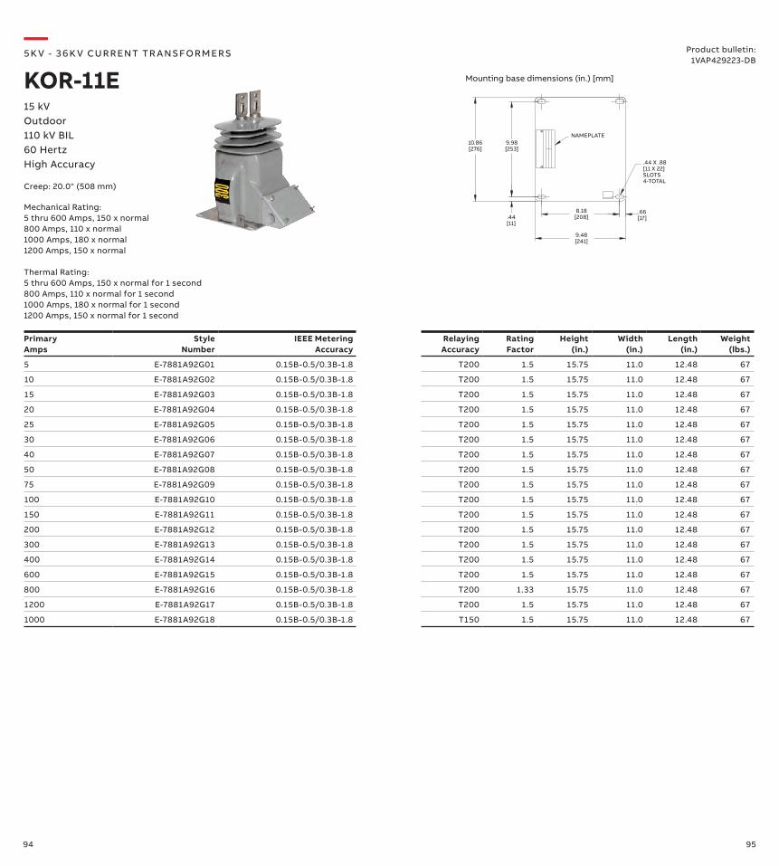
94 95
PrimaryAmps
Style Number
IEEE Metering Accuracy
Relaying Accuracy
Rating Factor
Height (in.)
Width (in.)
Length (in.)
Weight (lbs.)
5 E-7881A92G01 0.15B-0.5/0.3B-1.8 T200 1.5 15.75 11.0 12.48 67
10 E-7881A92G02 0.15B-0.5/0.3B-1.8 T200 1.5 15.75 11.0 12.48 67
15 E-7881A92G03 0.15B-0.5/0.3B-1.8 T200 1.5 15.75 11.0 12.48 67
20 E-7881A92G04 0.15B-0.5/0.3B-1.8 T200 1.5 15.75 11.0 12.48 67
25 E-7881A92G05 0.15B-0.5/0.3B-1.8 T200 1.5 15.75 11.0 12.48 67
30 E-7881A92G06 0.15B-0.5/0.3B-1.8 T200 1.5 15.75 11.0 12.48 67
40 E-7881A92G07 0.15B-0.5/0.3B-1.8 T200 1.5 15.75 11.0 12.48 67
50 E-7881A92G08 0.15B-0.5/0.3B-1.8 T200 1.5 15.75 11.0 12.48 67
75 E-7881A92G09 0.15B-0.5/0.3B-1.8 T200 1.5 15.75 11.0 12.48 67
100 E-7881A92G10 0.15B-0.5/0.3B-1.8 T200 1.5 15.75 11.0 12.48 67
150 E-7881A92G11 0.15B-0.5/0.3B-1.8 T200 1.5 15.75 11.0 12.48 67
200 E-7881A92G12 0.15B-0.5/0.3B-1.8 T200 1.5 15.75 11.0 12.48 67
300 E-7881A92G13 0.15B-0.5/0.3B-1.8 T200 1.5 15.75 11.0 12.48 67
400 E-7881A92G14 0.15B-0.5/0.3B-1.8 T200 1.5 15.75 11.0 12.48 67
600 E-7881A92G15 0.15B-0.5/0.3B-1.8 T200 1.5 15.75 11.0 12.48 67
800 E-7881A92G16 0.15B-0.5/0.3B-1.8 T200 1.33 15.75 11.0 12.48 67
1200 E-7881A92G17 0.15B-0.5/0.3B-1.8 T200 1.5 15.75 11.0 12.48 67
1000 E-7881A92G18 0.15B-0.5/0.3B-1.8 T150 1.5 15.75 11.0 12.48 67
10.86[276]
9.98[253]
.44[11]
8.18[208]
9.48[241]
.66[17]
NAMEPLATE
.44 X .88[11 X 22]SLOTS4-TOTAL
—5K V - 3 6 K V CU R R ENT TR A NS FO R M ER S
KOR-11E15 kVOutdoor110 kV BIL60 HertzHigh Accuracy
Mechanical Rating:5 thru 600 Amps, 150 x normal800 Amps, 110 x normal1000 Amps, 180 x normal1200 Amps, 150 x normal
Thermal Rating:5 thru 600 Amps, 150 x normal for 1 second800 Amps, 110 x normal for 1 second1000 Amps, 180 x normal for 1 second1200 Amps, 150 x normal for 1 second
Creep: 20.0" (508 mm)
Mounting base dimensions (in.) [mm]
Product bulletin:1VAP429223-DB
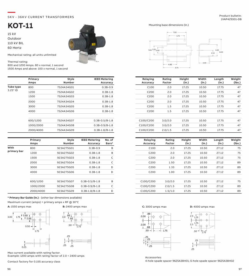
96 97
Primary Amps
Style Number
IEEE Metering Accuracy
Relaying Accuracy
Rating Factor
Height (in.)
Width (in.)
Length (in.)
Weight (lbs.)
Tube type3.25" ID
800 7524A34G01 0.3B-0.9 C100 2.0 17.25 10.50 17.75 47
1200 7524A34G02 0.3B-1.8 C200 2.0 17.25 10.50 17.75 47
1500 7524A34G03 0.3B-1.8 C200 2.0 17.25 10.50 17.75 47
2000 7524A34G04 0.3B-1.8 C200 2.0 17.25 10.50 17.75 47
3000 7524A34G05 0.3B-1.8 C200 1.5 17.25 10.50 17.75 47
4000 7524A34G06 0.3B-1.8 C200 1.5 17.25 10.50 17.75 47
600/1200 7524A34G07 0.3B-0.5/B-1.8 C100/C200 3.0/2.0 17.25 10.50 17.75 47
1000/2000 7524A34G08 0.3B-0.9/B-1.8 C100/C200 3.0/2.0 17.25 10.50 17.75 47
2000/4000 7524A34G09 0.3B-1.8/B-1.8 C100/C200 2.0/1.5 17.25 10.50 17.75 47
Primary Amps
Style Number
IEEE Metering Accuracy
No. of Bars*
Relaying Accuracy
Rating Factor
Height (in.)
Width (in.)
Length (in.)
Weight (lbs.)
With primary bar
800 923A275G01 0.3B-0.9 B C100 2.0 17.25 10.50 27.12 75
1200 923A275G02 0.3B-1.8 B C200 2.0 17.25 10.50 27.12 75
1500 923A275G03 0.3B-1.8 C C200 2.0 17.25 10.50 27.12 75
2000 923A275G04 0.3B-1.8 C C200 1.50 17.25 10.50 27.12 89
3000 923A275G05 0.3B-1.8 D C200 1.33 17.25 10.50 27.12 89
4000 923A275G06 0.3B-1.8 D C200 1.00 17.25 10.50 27.12 89
600/1200 923A275G07 0.3B-0.5/B-1.8 B C100/C200 3.0/2.0 17.25 10.50 27.12 75
1000/2000 923A275G08 0.3B-0.9/B-1.8 C C100/C200 2.0/1.5 17.25 10.50 27.12 89
2000/4000 923A275G09 0.3B-1.8/B-1.8 D C100/C200 1.5/1.0 17.25 10.50 27.12 89
—5K V - 3 6 K V CU R R ENT TR A NS FO R M ER S
KOT-1115 kVOutdoor110 kV BIL60 Hertz
Mechanical rating: all units unlimited
Thermal rating:800 and 1200 Amps: 80 x normal, 1 second1500 Amps and above: 100 x normal, 1 second
Product bulletin:1VAP429301-DB
Mounting base dimensions (in.)
3.00 1.75 0.88
0.50
1.75
0.25
0.88
1.75.50
.88.883.0
.25.25
.25
1.75
1.75
2.5
2.5
.50 1.75
.25
.25.25
.25.25
.50 1.75.88
.882.00
2.00
* Primary Bar Guide (in.) - (other bar dimensions available)
Maximum current (amps) = primary amps x RF @ 30°C
Contact factory for 0.15S accuracy class
Max current available with rating factor. Example: 1200 amps with rating factor of 2.0 = 2400 amps Accessories:
4-hole spade spacer 9625A38H01; 6-hole spade spacer 9625A38H02
B: 2400 amps max D: 4000 amps maxA: 1550 amps max C: 3000 amps max
2.13
4.258.25
4.00
3.25
5.75
7.00
4.88
9.75
2.007.00
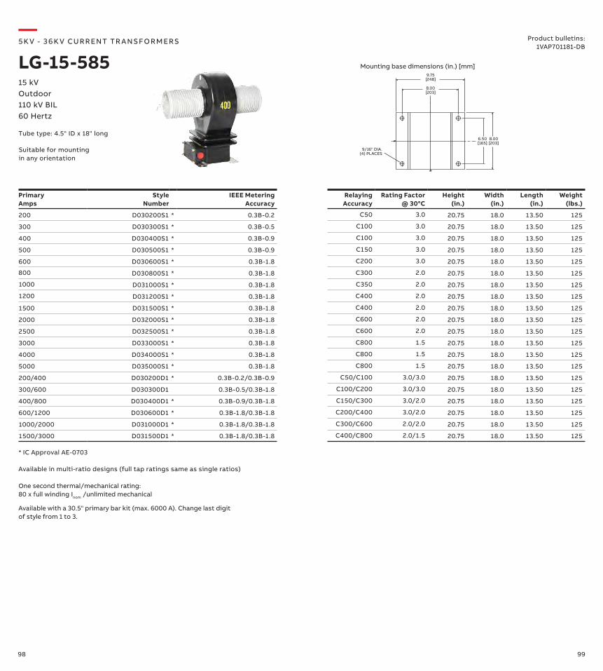
98 99
Primary Amps
Style Number
IEEE Metering Accuracy
Relaying Accuracy
Rating Factor @ 30°C
Height (in.)
Width (in.)
Length (in.)
Weight (lbs.)
200 D030200S1 * 0.3B-0.2 C50 3.0 20.75 18.0 13.50 125
300 D030300S1 * 0.3B-0.5 C100 3.0 20.75 18.0 13.50 125
400 D030400S1 * 0.3B-0.9 C100 3.0 20.75 18.0 13.50 125
500 D030500S1 * 0.3B-0.9 C150 3.0 20.75 18.0 13.50 125
600 D030600S1 * 0.3B-1.8 C200 3.0 20.75 18.0 13.50 125
800 D030800S1 * 0.3B-1.8 C300 2.0 20.75 18.0 13.50 125
1000 D031000S1 * 0.3B-1.8 C350 2.0 20.75 18.0 13.50 125
1200 D031200S1 * 0.3B-1.8 C400 2.0 20.75 18.0 13.50 125
1500 D031500S1 * 0.3B-1.8 C400 2.0 20.75 18.0 13.50 125
2000 D032000S1 * 0.3B-1.8 C600 2.0 20.75 18.0 13.50 125
2500 D032500S1 * 0.3B-1.8 C600 2.0 20.75 18.0 13.50 125
3000 D033000S1 * 0.3B-1.8 C800 1.5 20.75 18.0 13.50 125
4000 D034000S1 * 0.3B-1.8 C800 1.5 20.75 18.0 13.50 125
5000 D035000S1 * 0.3B-1.8 C800 1.5 20.75 18.0 13.50 125
200/400 D030200D1 * 0.3B-0.2/0.3B-0.9 C50/C100 3.0/3.0 20.75 18.0 13.50 125
300/600 D030300D1 0.3B-0.5/0.3B-1.8 C100/C200 3.0/3.0 20.75 18.0 13.50 125
400/800 D030400D1 * 0.3B-0.9/0.3B-1.8 C150/C300 3.0/2.0 20.75 18.0 13.50 125
600/1200 D030600D1 * 0.3B-1.8/0.3B-1.8 C200/C400 3.0/2.0 20.75 18.0 13.50 125
1000/2000 D031000D1 * 0.3B-1.8/0.3B-1.8 C300/C600 2.0/2.0 20.75 18.0 13.50 125
1500/3000 D031500D1 * 0.3B-1.8/0.3B-1.8 C400/C800 2.0/1.5 20.75 18.0 13.50 125
9.75[248]
9/16" DIA.(4) PLACES
8.00[203]
6.50[165]
8.00[203]
Available in multi-ratio designs (full tap ratings same as single ratios)
Available with a 30.5" primary bar kit (max. 6000 A). Change last digit of style from 1 to 3.
* IC Approval AE-0703
One second thermal/mechanical rating: 80 x full winding Inom /unlimited mechanical
—5K V - 3 6 K V CU R R ENT TR A NS FO R M ER S
LG-15-58515 kVOutdoor110 kV BIL60 Hertz
Product bulletins: 1VAP701181-DB
Suitable for mounting in any orientation
Tube type: 4.5" ID x 18" long
Mounting base dimensions (in.) [mm]
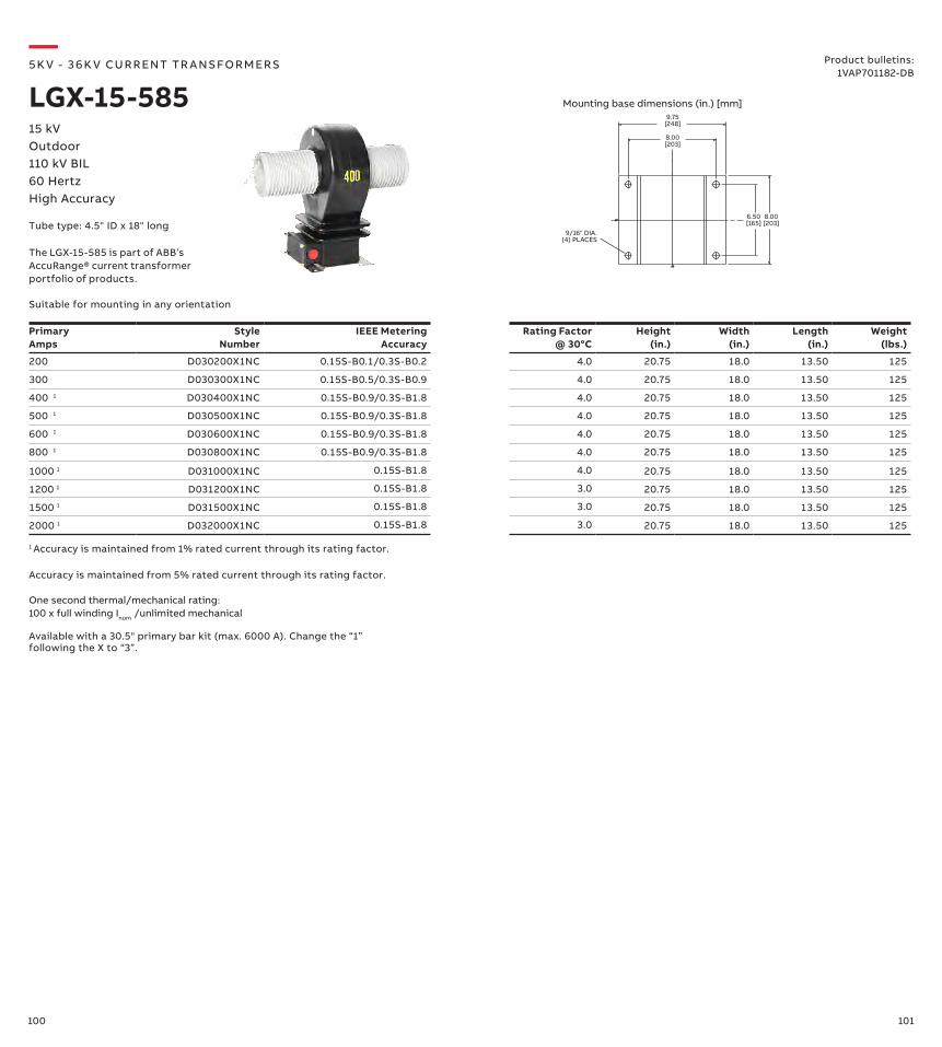
100 101
9.75[248]
9/16" DIA.(4) PLACES
8.00[203]
6.50[165]
8.00[203]
—5K V - 3 6 K V CU R R ENT TR A NS FO R M ER S
LGX-15-58515 kVOutdoor110 kV BIL60 HertzHigh Accuracy
Product bulletins:1VAP701182-DB
Suitable for mounting in any orientation
Tube type: 4.5" ID x 18" long
Mounting base dimensions (in.) [mm]
Primary Amps
Style Number
IEEE Metering Accuracy
Rating Factor @ 30°C
Height (in.)
Width (in.)
Length (in.)
Weight (lbs.)
200 D030200X1NC 0.15S-B0.1/0.3S-B0.2 4.0 20.75 18.0 13.50 125
300 D030300X1NC 0.15S-B0.5/0.3S-B0.9 4.0 20.75 18.0 13.50 125
400 1 D030400X1NC 0.15S-B0.9/0.3S-B1.8 4.0 20.75 18.0 13.50 125
500 1 D030500X1NC 0.15S-B0.9/0.3S-B1.8 4.0 20.75 18.0 13.50 125
600 1 D030600X1NC 0.15S-B0.9/0.3S-B1.8 4.0 20.75 18.0 13.50 125
800 1 D030800X1NC 0.15S-B0.9/0.3S-B1.8 4.0 20.75 18.0 13.50 125
1000 1 D031000X1NC 0.15S-B1.8 4.0 20.75 18.0 13.50 125
1200 1 D031200X1NC 0.15S-B1.8 3.0 20.75 18.0 13.50 125
1500 1 D031500X1NC 0.15S-B1.8 3.0 20.75 18.0 13.50 125
2000 1 D032000X1NC 0.15S-B1.8 3.0 20.75 18.0 13.50 125
One second thermal/mechanical rating: 100 x full winding Inom /unlimited mechanical
Accuracy is maintained from 5% rated current through its rating factor.
1 Accuracy is maintained from 1% rated current through its rating factor.
Available with a 30.5" primary bar kit (max. 6000 A). Change the “1” following the X to “3”.
The LGX-15-585 is part of ABB’s AccuRange® current transformer portfolio of products.
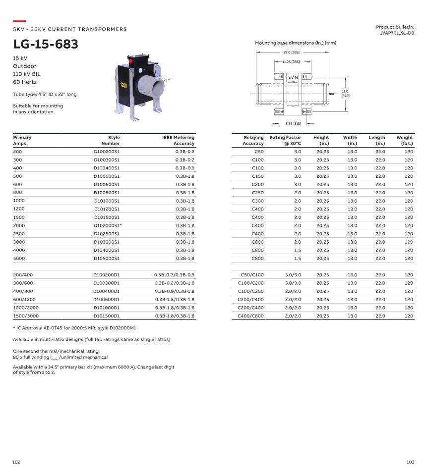
102 103
Primary Amps
Style Number
IEEE Metering Accuracy
Relaying Accuracy
Rating Factor @ 30°C
Height (in.)
Width (in.)
Length (in.)
Weight (lbs.)
200 D100200S1 0.3B-0.2 C50 3.0 20.25 13.0 22.0 120
300 D100300S1 0.3B-0.2 C100 3.0 20.25 13.0 22.0 120
400 D100400S1 0.3B-0.9 C100 3.0 20.25 13.0 22.0 120
500 D100500S1 0.3B-1.8 C150 3.0 20.25 13.0 22.0 120
600 D100600S1 0.3B-1.8 C200 3.0 20.25 13.0 22.0 120
800 D100800S1 0.3B-1.8 C250 2.0 20.25 13.0 22.0 120
1000 D101000S1 0.3B-1.8 C300 2.0 20.25 13.0 22.0 120
1200 D101200S1 0.3B-1.8 C400 2.0 20.25 13.0 22.0 120
1500 D101500S1 0.3B-1.8 C400 2.0 20.25 13.0 22.0 120
2000 D102000S1* 0.3B-1.8 C400 2.0 20.25 13.0 22.0 120
2500 D102500S1 0.3B-1.8 C400 2.0 20.25 13.0 22.0 120
3000 D103000S1 0.3B-1.8 C800 2.0 20.25 13.0 22.0 120
4000 D104000S1 0.3B-1.8 C800 1.5 20.25 13.0 22.0 120
5000 D105000S1 0.3B-1.8 C800 1.5 20.25 13.0 22.0 120
200/400 D100200D1 0.3B-0.2/0.3B-0.9 C50/C100 3.0/3.0 20.25 13.0 22.0 120
300/600 D100300D1 0.3B-0.2/0.3B-1.8 C100/C200 3.0/3.0 20.25 13.0 22.0 120
400/800 D100400D1 0.3B-0.9/0.3B-1.8 C100/C200 2.0/2.0 20.25 13.0 22.0 120
600/1200 D100600D1 0.3B-1.8/0.3B-1.8 C200/C400 2.0/2.0 20.25 13.0 22.0 120
1000/2000 D101000D1 0.3B-1.8/0.3B-1.8 C200/C400 2.0/2.0 20.25 13.0 22.0 120
1500/3000 D101500D1 0.3B-1.8/0.3B-1.8 C400/C800 2.0/2.0 20.25 13.0 22.0 120
* IC Approval AE-0745 for 2000:5 MR, style D102000M1
Available in multi-ratio designs (full tap ratings same as single ratios)
One second thermal/mechanical rating: 80 x full winding Inom /unlimited mechanical
8.25 [210]
22.0 [559]
N/P
[279]11.0
11.25 [286]
Available with a 34.5" primary bar kit (maximum 6000 A). Change last digit of style from 1 to 3.
—5K V - 3 6 K V CU R R ENT TR A NS FO R M ER S
LG-15-68315 kVOutdoor110 kV BIL60 Hertz
Product bulletin:1VAP701191-DB
Mounting base dimensions (in.) [mm]
Tube type: 4.5" ID x 22" long
Suitable for mounting in any orientation
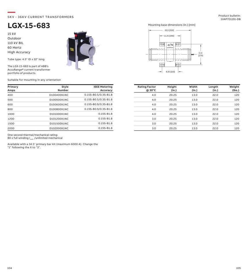
104 105
8.25 [210]
22.0 [559]
N/P
[279]11.0
11.25 [286]
—5K V - 3 6 K V CU R R ENT TR A NS FO R M ER S
LGX-15-68315 kVOutdoor110 kV BIL60 HertzHigh Accuracy
Product bulletin:1VAP701191-DB
Mounting base dimensions (in.) [mm]
Tube type: 4.5" ID x 22" long
Suitable for mounting in any orientation
Primary Amps
Style Number
IEEE Metering Accuracy
Rating Factor @ 30°C
Height (in.)
Width (in.)
Length (in.)
Weight (lbs.)
400 D100400X1NC 0.15S-B0.5/0.3S-B1.8 4.0 20.25 13.0 22.0 120
500 D100500X1NC 0.15S-B0.5/0.3S-B1.8 4.0 20.25 13.0 22.0 120
600 D100600X1NC 0.15S-B0.9/0.3S-B1.8 4.0 20.25 13.0 22.0 120
800 D100800X1NC 0.15S-B0.9/0.3S-B1.8 4.0 20.25 13.0 22.0 120
1000 D101000X1NC 0.15S-B1.8 4.0 20.25 13.0 22.0 120
1200 D101200X1NC 0.15S-B1.8 3.0 20.25 13.0 22.0 120
1500 D101500X1NC 0.15S-B1.8 3.0 20.25 13.0 22.0 120
2000 D102000X1NC 0.15S-B1.8 3.0 20.25 13.0 22.0 120
One second thermal/mechanical rating: 80 x full winding Inom /unlimited mechanical
Available with a 34.5" primary bar kit (maximum 6000 A). Change the “1” following the X to “3”.
The LGX-15-683 is part of ABB’s AccuRange® current transformer portfolio of products.
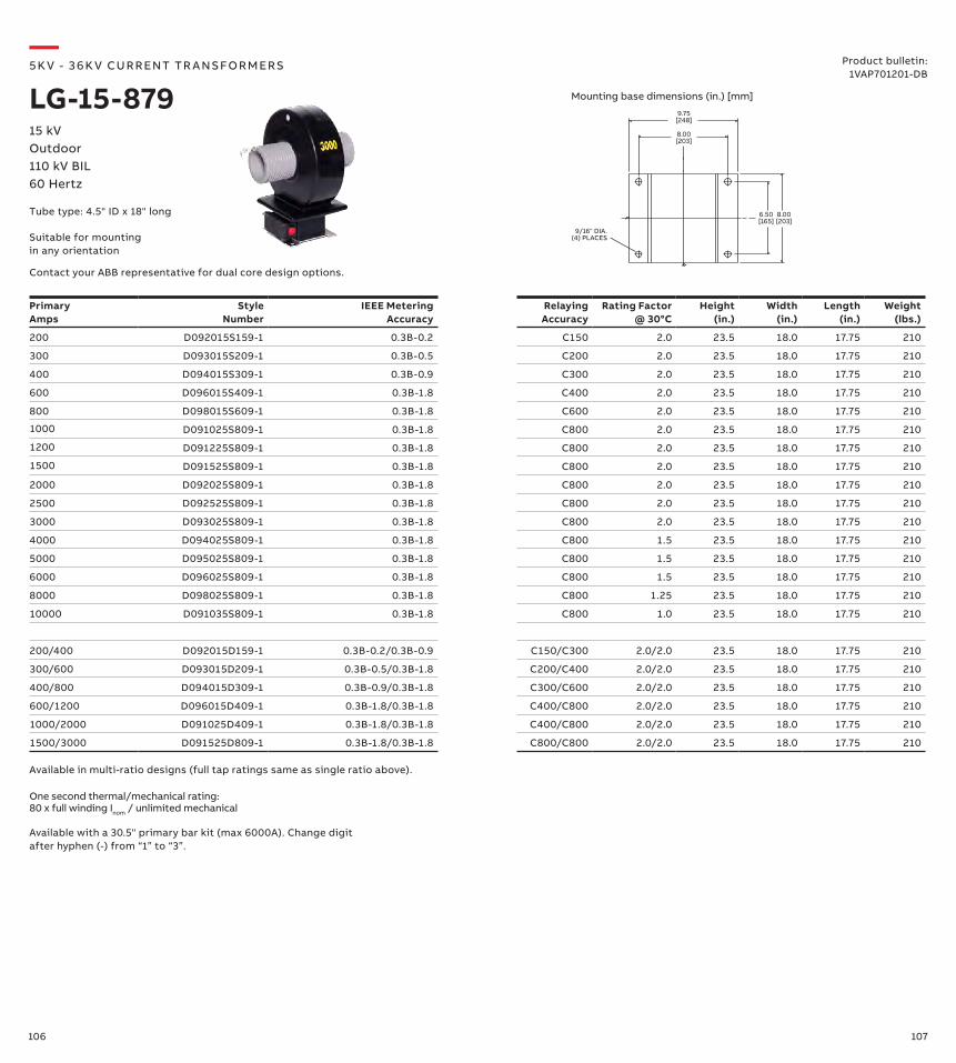
106 107
Primary Amps
Style Number
IEEE Metering Accuracy
Relaying Accuracy
Rating Factor @ 30°C
Height (in.)
Width (in.)
Length (in.)
Weight (lbs.)
200 D092015S159-1 0.3B-0.2 C150 2.0 23.5 18.0 17.75 210
300 D093015S209-1 0.3B-0.5 C200 2.0 23.5 18.0 17.75 210
400 D094015S309-1 0.3B-0.9 C300 2.0 23.5 18.0 17.75 210
600 D096015S409-1 0.3B-1.8 C400 2.0 23.5 18.0 17.75 210
800 D098015S609-1 0.3B-1.8 C600 2.0 23.5 18.0 17.75 210
1000 D091025S809-1 0.3B-1.8 C800 2.0 23.5 18.0 17.75 210
1200 D091225S809-1 0.3B-1.8 C800 2.0 23.5 18.0 17.75 210
1500 D091525S809-1 0.3B-1.8 C800 2.0 23.5 18.0 17.75 210
2000 D092025S809-1 0.3B-1.8 C800 2.0 23.5 18.0 17.75 210
2500 D092525S809-1 0.3B-1.8 C800 2.0 23.5 18.0 17.75 210
3000 D093025S809-1 0.3B-1.8 C800 2.0 23.5 18.0 17.75 210
4000 D094025S809-1 0.3B-1.8 C800 1.5 23.5 18.0 17.75 210
5000 D095025S809-1 0.3B-1.8 C800 1.5 23.5 18.0 17.75 210
6000 D096025S809-1 0.3B-1.8 C800 1.5 23.5 18.0 17.75 210
8000 D098025S809-1 0.3B-1.8 C800 1.25 23.5 18.0 17.75 210
10000 D091035S809-1 0.3B-1.8 C800 1.0 23.5 18.0 17.75 210
200/400 D092015D159-1 0.3B-0.2/0.3B-0.9 C150/C300 2.0/2.0 23.5 18.0 17.75 210
300/600 D093015D209-1 0.3B-0.5/0.3B-1.8 C200/C400 2.0/2.0 23.5 18.0 17.75 210
400/800 D094015D309-1 0.3B-0.9/0.3B-1.8 C300/C600 2.0/2.0 23.5 18.0 17.75 210
600/1200 D096015D409-1 0.3B-1.8/0.3B-1.8 C400/C800 2.0/2.0 23.5 18.0 17.75 210
1000/2000 D091025D409-1 0.3B-1.8/0.3B-1.8 C400/C800 2.0/2.0 23.5 18.0 17.75 210
1500/3000 D091525D809-1 0.3B-1.8/0.3B-1.8 C800/C800 2.0/2.0 23.5 18.0 17.75 210
Available in multi-ratio designs (full tap ratings same as single ratio above).
One second thermal/mechanical rating: 80 x full winding Inom / unlimited mechanical
Available with a 30.5" primary bar kit (max 6000A). Change digit after hyphen (-) from “1” to “3”.
9.75[248]
9/16" DIA.(4) PLACES
8.00[203]
6.50[165]
8.00[203]
—5K V - 3 6 K V CU R R ENT TR A NS FO R M ER S
LG-15-87915 kVOutdoor110 kV BIL60 Hertz
Product bulletin:1VAP701201-DB
Contact your ABB representative for dual core design options.
Mounting base dimensions (in.) [mm]
Tube type: 4.5" ID x 18" long
Suitable for mounting in any orientation
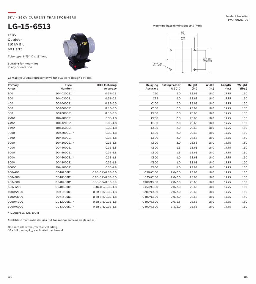
108 109
Primary Amps
Style Number
IEEE Metering Accuracy
Relaying Accuracy
Rating Factor @ 30°C
Height (in.)
Width (in.)
Length (in.)
Weight (lbs.)
200 D040200S1 0.6B-0.2 C50 2.0 23.63 18.0 17.75 150
300 D040300S1 0.6B-0.2 C75 2.0 23.63 18.0 17.75 150
400 D040400S1 0.3B-0.5 C100 2.0 23.63 18.0 17.75 150
600 D040600S1 0.3B-0.5 C150 2.0 23.63 18.0 17.75 150
800 D040800S1 0.3B-0.9 C200 2.0 23.63 18.0 17.75 150
1000 D041000S1 0.3B-1.8 C250 2.0 23.63 18.0 17.75 150
1200 D041200S1 0.3B-1.8 C300 2.0 23.63 18.0 17.75 150
1500 D041500S1 0.3B-1.8 C400 2.0 23.63 18.0 17.75 150
2000 D042000S1 * 0.3B-1.8 C500 2.0 23.63 18.0 17.75 150
2500 D042500S1 0.3B-1.8 C600 2.0 23.63 18.0 17.75 150
3000 D043000S1 * 0.3B-1.8 C800 2.0 23.63 18.0 17.75 150
4000 D044000S1 0.3B-1.8 C800 1.5 23.63 18.0 17.75 150
5000 D045000S1 0.3B-1.8 C800 1.5 23.63 18.0 17.75 150
6000 D046000S1 * 0.3B-1.8 C800 1.0 23.63 18.0 17.75 150
8000 D048000S1 0.3B-1.8 C800 1.0 23.63 18.0 17.75 150
10000 D041000S1 0.3B-1.8 C800 1.0 23.63 18.0 17.75 150
200/400 D040200D1 0.6B-0.2/0.3B-0.5 C50/C100 2.0/2.0 23.63 18.0 17.75 150
300/600 D040300D1 0.6B-0.2/0.3B-0.5 C75/C150 2.0/2.0 23.63 18.0 17.75 150
400/800 D040400D1 0.3B-0.5/0.3B-0.9 C100/C200 2.0/2.0 23.63 18.0 17.75 150
600/1200 D040600D1 0.3B-0.5/0.3B-1.8 C150/C300 2.0/2.0 23.63 18.0 17.75 150
1000/2000 D041000D1 0.3B-1.8/0.3B-1.8 C200/C400 2.0/2.0 23.63 18.0 17.75 150
1500/3000 D041500D1 0.3B-1.8/0.3B-1.8 C400/C800 2.0/2.0 23.63 18.0 17.75 150
2000/4000 D042000D1 * 0.3B-1.8/0.3B-1.8 C400/C800 2.0/1.5 23.63 18.0 17.75 150
3000/6000 D043000D1 * 0.3B-1.8/0.3B-1.8 C400/C800 1.5/1.0 23.63 18.0 17.75 150
* IC Approval (AE-1104)
One second thermal/mechanical rating: 80 x full winding Inom / unlimited mechanical
Available in multi-ratio designs (full tap ratings same as single ratios)
9.75[248]
9/16" DIA.(4) PLACES
8.00[203]
6.50[165]
8.00[203]
—5K V - 3 6 K V CU R R ENT TR A NS FO R M ER S
LG-15-651315 kVOutdoor110 kV BIL60 Hertz
Product bulletin:1VAP701211-DB
Mounting base dimensions (in.) [mm]
Tube type: 8.75" ID x 18" long
Contact your ABB representative for dual core design options.
Suitable for mounting in any orientation
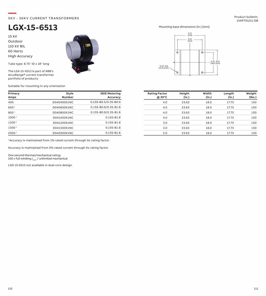
110 111
9.75[248]
9/16" DIA.(4) PLACES
8.00[203]
6.50[165]
8.00[203]
—5K V - 3 6 K V CU R R ENT TR A NS FO R M ER S
LGX-15-651315 kVOutdoor110 kV BIL60 HertzHigh Accuracy
Product bulletin:1VAP701211-DB
Mounting base dimensions (in.) [mm]
Tube type: 8.75" ID x 18" long
Suitable for mounting in any orientation
Primary Amps
Style Number
IEEE MeteringAccuracy
Rating Factor @ 30°C
Height (in.)
Width (in.)
Length (in.)
Weight (lbs.)
400 D040400X1NC 0.15S-B0.5/0.3S-B0.9 4.0 23.63 18.0 17.75 150
600 1 D040600X1NC 0.15S-B0.9/0.3S-B1.8 4.0 23.63 18.0 17.75 150
800 1 D040800X1NC 0.15S-B0.9/0.3S-B1.8 4.0 23.63 18.0 17.75 150
1000 1 D041000X1NC 0.15S-B1.8 4.0 23.63 18.0 17.75 150
1200 1 D041200X1NC 0.15S-B1.8 3.0 23.63 18.0 17.75 150
1500 1 D041500X1NC 0.15S-B1.8 3.0 23.63 18.0 17.75 150
2000 1 D042000X1NC 0.15S-B1.8 2.0 23.63 18.0 17.75 150
One second thermal/mechanical rating: 100 x full winding Inom / unlimited mechanical
Accuracy is maintained from 5% rated current through its rating factor.
LGX-15-6513 not available in dual-core design.
1 Accuracy is maintained from 1% rated current through its rating factor.
The LGX-15-6513 is part of ABB’s AccuRange® current transformer portfolio of products.
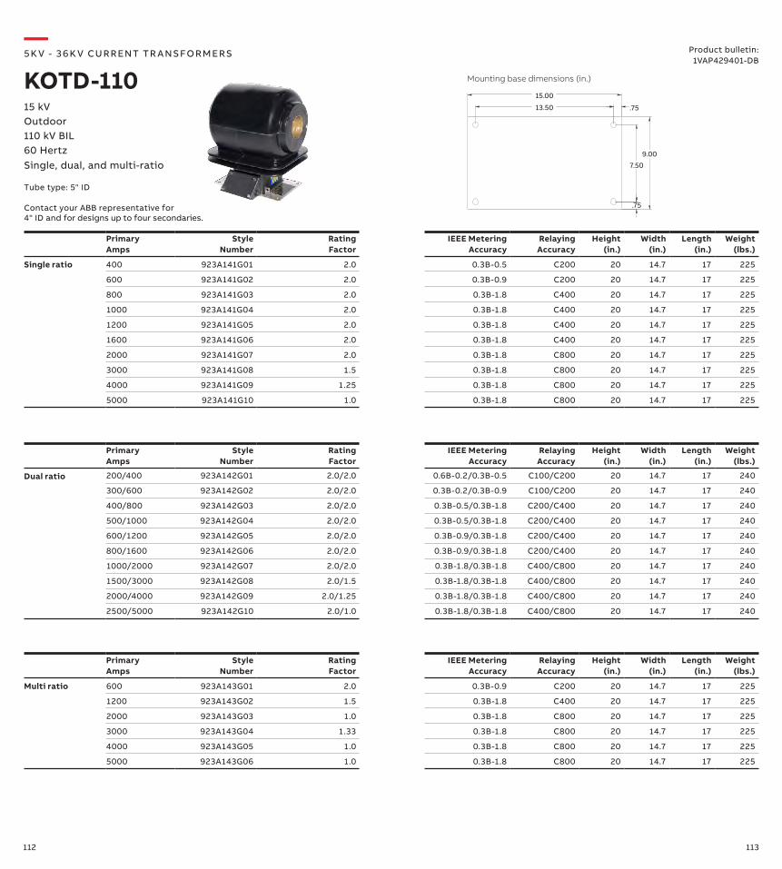
112 113
PrimaryAmps
Style Number
Rating Factor
IEEE Metering Accuracy
Relaying Accuracy
Height (in.)
Width (in.)
Length (in.)
Weight (lbs.)
Single ratio 400 923A141G01 2.0 0.3B-0.5 C200 20 14.7 17 225
600 923A141G02 2.0 0.3B-0.9 C200 20 14.7 17 225
800 923A141G03 2.0 0.3B-1.8 C400 20 14.7 17 225
1000 923A141G04 2.0 0.3B-1.8 C400 20 14.7 17 225
1200 923A141G05 2.0 0.3B-1.8 C400 20 14.7 17 225
1600 923A141G06 2.0 0.3B-1.8 C400 20 14.7 17 225
2000 923A141G07 2.0 0.3B-1.8 C800 20 14.7 17 225
3000 923A141G08 1.5 0.3B-1.8 C800 20 14.7 17 225
4000 923A141G09 1.25 0.3B-1.8 C800 20 14.7 17 225
5000 923A141G10 1.0 0.3B-1.8 C800 20 14.7 17 225
7.50
.75
9.00
13.50 .75
15.00
PrimaryAmps
Style Number
Rating Factor
IEEE Metering Accuracy
Relaying Accuracy
Height (in.)
Width (in.)
Length (in.)
Weight (lbs.)
Dual ratio 200/400 923A142G01 2.0/2.0 0.6B-0.2/0.3B-0.5 C100/C200 20 14.7 17 240
300/600 923A142G02 2.0/2.0 0.3B-0.2/0.3B-0.9 C100/C200 20 14.7 17 240
400/800 923A142G03 2.0/2.0 0.3B-0.5/0.3B-1.8 C200/C400 20 14.7 17 240
500/1000 923A142G04 2.0/2.0 0.3B-0.5/0.3B-1.8 C200/C400 20 14.7 17 240
600/1200 923A142G05 2.0/2.0 0.3B-0.9/0.3B-1.8 C200/C400 20 14.7 17 240
800/1600 923A142G06 2.0/2.0 0.3B-0.9/0.3B-1.8 C200/C400 20 14.7 17 240
1000/2000 923A142G07 2.0/2.0 0.3B-1.8/0.3B-1.8 C400/C800 20 14.7 17 240
1500/3000 923A142G08 2.0/1.5 0.3B-1.8/0.3B-1.8 C400/C800 20 14.7 17 240
2000/4000 923A142G09 2.0/1.25 0.3B-1.8/0.3B-1.8 C400/C800 20 14.7 17 240
2500/5000 923A142G10 2.0/1.0 0.3B-1.8/0.3B-1.8 C400/C800 20 14.7 17 240
PrimaryAmps
Style Number
Rating Factor
IEEE Metering Accuracy
Relaying Accuracy
Height (in.)
Width (in.)
Length (in.)
Weight (lbs.)
Multi ratio 600 923A143G01 2.0 0.3B-0.9 C200 20 14.7 17 225
1200 923A143G02 1.5 0.3B-1.8 C400 20 14.7 17 225
2000 923A143G03 1.0 0.3B-1.8 C800 20 14.7 17 225
3000 923A143G04 1.33 0.3B-1.8 C800 20 14.7 17 225
4000 923A143G05 1.0 0.3B-1.8 C800 20 14.7 17 225
5000 923A143G06 1.0 0.3B-1.8 C800 20 14.7 17 225
—5K V - 3 6 K V CU R R ENT TR A NS FO R M ER S
KOTD-11015 kVOutdoor110 kV BIL60 HertzSingle, dual, and multi-ratio
Product bulletin:1VAP429401-DB
Mounting base dimensions (in.)
Contact your ABB representative for 4" ID and for designs up to four secondaries.
Tube type: 5" ID

114 115
Primary Amps
Style Number
No. of Bars
Rating Factor
IEEE Metering Accuracy
Relaying Accuracy
Height (in.)
Width (in.)
Length (in.)
Weight (lbs.)
Single ratio 400 923A206G01 1 2.0 0.3B-0.5 C200 20 14.7 25 240
600 923A206G02 1 2.0 0.3B-0.9 C200 20 14.7 25 240
800 923A206G03 1 2.0 0.3B-1.8 C400 20 14.7 25 240
1000 923A206G04 1 2.0 0.3B-1.8 C400 20 14.7 25 240
1200 923A206G05 1 1.5 0.3B-1.8 C400 20 14.7 25 240
1600 923A206G06 1 1.25 0.3B-1.8 C400 20 14.7 25 240
2000 923A206G07 1 1.0 0.3B-1.8 C800 20 14.7 25 240
3000 923A206G08 2 1.33 0.3B-1.8 C800 20 14.7 25 240
4000 923A206G09 2 1.0 0.3B-1.8 C800 20 14.7 25 240
5000 923A206G10 3 1.0 0.3B-1.8 C800 20 14.7 25 240
Primary Amps
Style Number
No. of Bars
Rating Factor
IEEE Metering Accuracy
Relaying Accuracy
Height (in.)
Width (in.)
Length (in.)
Weight (lbs.)
Dual ratio 200/400 923A148G01 1 2.0/2.0 0.6B-0.2/0.3B-0.5 C100/C200 20 14.7 25 240
300/600 923A148G02 1 2.0/2.0 0.3B-0.2/0.3B-0.9 C100/C200 20 14.7 25 240
400/800 923A148G03 1 2.0/2.0 0.3B-0.5/0.3B-1.8 C200/C400 20 14.7 25 240
500/1000 923A148G04 1 2.0/2.0 0.3B-0.5/0.3B-1.8 C200/C400 20 14.7 25 240
600/1200 923A148G05 1 2.0/1.5 0.3B-0.9/0.3B-1.8 C200/C400 20 14.7 25 240
800/1600 923A148G06 1 2.0/1.25 0.3B-0.9/0.3B-1.8 C200/C400 20 14.7 25 240
1000/2000 923A148G07 1 2.0/1.0 0.3B-1.8/0.3B-1.8 C400/C800 20 14.7 25 240
1500/3000 923A148G08 2 2.0/1.33 0.3B-1.8/0.3B-1.8 C400/C800 20 14.7 25 240
2000/4000 923A148G09 2 2.0/1.0 0.3B-1.8/0.3B-1.8 C400/C800 20 14.7 25 240
2500/5000 923A148G10 3 2.0/1.0 0.3B-1.8/0.3B-1.8 C400/C800 20 14.7 25 240
Primary Amps
Style Number
No. of Bars
Rating Factor
IEEE Metering Accuracy
Relaying Accuracy
Height (in.)
Width (in.)
Length (in.)
Weight (lbs.)
Multi ratio 600 923A149G01 1 2.0 0.3B-0.9 C200 20 15.3 25 240
1200 923A149G02 1 1.5 0.3B-1.8 C400 20 15.3 25 240
2000 923A149G03 1 1.0 0.3B-1.8 C800 20 15.3 25 240
3000 923A149G04 2 1.33 0.3B-1.8 C800 20 15.3 25 240
4000 923A149G05 2 1.0 0.3B-1.8 C800 20 15.3 25 240
5000 923A149G06 3 1.0 0.3B-1.8 C800 20 15.3 25 240
Note: Base dimensions same as tube type KOTD
25.0
4.0
1.12
1.75
1.75
23.88
.56
Ø.56 8-TOTAL
.50
3.0
—5K V - 3 6 K V CU R R ENT TR A NS FO R M ER S
KOTD-11015 kVOutdoor110 kV BIL60 HertzSingle, dual, and multi-ratioWith primary bar
Contact your ABB representative for designs up to four secondaries.
Bar dimensions (in.)
Product bulletin:1VAP429401-DB
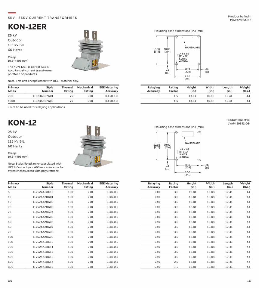
116 117
—5K V - 3 6 K V CU R R ENT TR A NS FO R M ER S
KON-12ER25 kVOutdoor125 kV BIL60 Hertz
Product bulletin:1VAP429251-DB
10.88 [276]
10.00 [254]
.44[11]
8.19[208]
9.50[241]
.66 [17]
.44 x .88[11 x 22]SLOTS4-TOTAL
NAMEPLATE
Primary Amps
Style Number
Thermal Rating
Mechanical Rating
IEEE Metering Accuracy
Relaying Accuracy
Rating Factor
Height (in.)
Width (in.)
Length (in.)
Weight (lbs.)
5 E-7524A28G16 190 270 0.3B-0.5 C40 3.0 13.81 10.88 12.41 44
10 E-7524A28G01 190 270 0.3B-0.5 C40 3.0 13.81 10.88 12.41 44
15 E-7524A28G02 190 270 0.3B-0.5 C40 3.0 13.81 10.88 12.41 44
20 E-7524A28G03 190 270 0.3B-0.5 C40 3.0 13.81 10.88 12.41 44
25 E-7524A28G04 190 270 0.3B-0.5 C40 3.0 13.81 10.88 12.41 44
30 E-7524A28G05 190 270 0.3B-0.5 C40 3.0 13.81 10.88 12.41 44
40 E-7524A28G06 190 270 0.3B-0.5 C40 3.0 13.81 10.88 12.41 44
50 E-7524A28G07 190 270 0.3B-0.5 C40 3.0 13.81 10.88 12.41 44
75 E-7524A28G08 190 270 0.3B-0.5 C40 3.0 13.81 10.88 12.41 44
100 E-7524A28G09 190 270 0.3B-0.5 C40 3.0 13.81 10.88 12.41 44
150 E-7524A28G10 190 270 0.3B-0.5 C40 3.0 13.81 10.88 12.41 44
200 E-7524A28G11 190 270 0.3B-0.5 C40 3.0 13.81 10.88 12.41 44
300 E-7524A28G12 190 270 0.3B-0.5 C40 3.0 13.81 10.88 12.41 44
400 E-7524A28G13 190 270 0.3B-0.5 C40 3.0 13.81 10.88 12.41 44
600 E-7524A28G14 190 270 0.3B-0.5 C40 2.0 13.81 10.88 12.41 44
800 E-7524A28G15 190 270 0.3B-0.5 C40 1.5 13.81 10.88 12.41 44
Creep:19.5" (495 mm)
Mounting base dimensions (in.) [mm]
Note: Styles listed are encapsulated with HCEP. Contact your ABB representative for styles encapsulated with polyurethane.
KON-1225 kVOutdoor125 kV BIL60 Hertz 10.88
[276]10.00 [254]
.44[11]
8.19[208]
9.50[241]
.66 [17]
.44 x .88[11 x 22]SLOTS4-TOTAL
NAMEPLATE
Mounting base dimensions (in.) [mm]
Creep:19.5" (495 mm)
Primary Amps
Style Number
Thermal Rating
Mechanical Rating
IEEE Metering Accuracy
Relaying Accuracy
Rating Factor
Height (in.)
Width (in.)
Length (in.)
Weight (lbs.)
200 E-923A507G01 75 200 0.15B-1.8 + 1.5 13.81 10.88 12.41 44
1000 E-923A507G02 75 200 0.15B-1.8 + 1.5 13.81 10.88 12.41 44
+ Not to be used for relaying applications
The KON-12ER is part of ABB’s AccuRange® current transformer portfolio of products.
Note: This unit encapsulated with HCEP material only.
Product bulletin:1VAP429252-DB
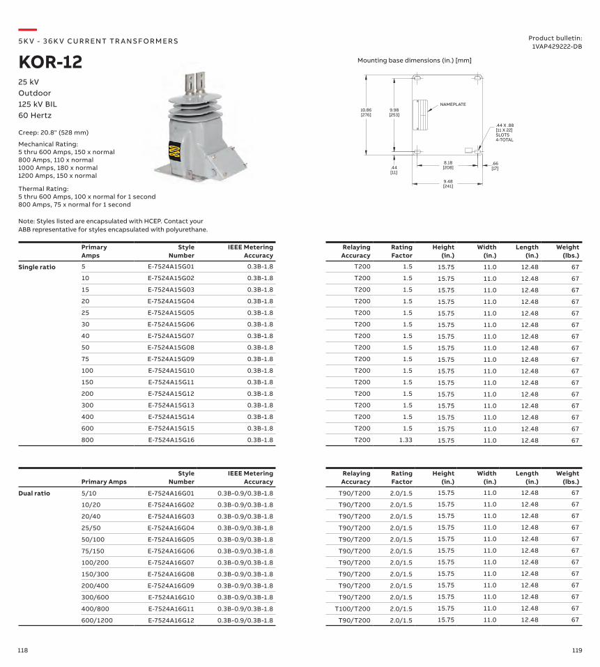
118 119
—5K V - 3 6 K V CU R R ENT TR A NS FO R M ER S
KOR-1225 kVOutdoor125 kV BIL60 Hertz
Product bulletin:1VAP429222-DB
Mounting base dimensions (in.) [mm]
10.86[276]
9.98[253]
.44[11]
8.18[208]
9.48[241]
.66[17]
NAMEPLATE
.44 X .88[11 X 22]SLOTS4-TOTAL
Primary AmpsStyle
NumberIEEE Metering
AccuracyRelaying Accuracy
Rating Factor
Height (in.)
Width (in.)
Length (in.)
Weight (lbs.)
Dual ratio 5/10 E-7524A16G01 0.3B-0.9/0.3B-1.8 T90/T200 2.0/1.5 15.75 11.0 12.48 67
10/20 E-7524A16G02 0.3B-0.9/0.3B-1.8 T90/T200 2.0/1.5 15.75 11.0 12.48 67
20/40 E-7524A16G03 0.3B-0.9/0.3B-1.8 T90/T200 2.0/1.5 15.75 11.0 12.48 67
25/50 E-7524A16G04 0.3B-0.9/0.3B-1.8 T90/T200 2.0/1.5 15.75 11.0 12.48 67
50/100 E-7524A16G05 0.3B-0.9/0.3B-1.8 T90/T200 2.0/1.5 15.75 11.0 12.48 67
75/150 E-7524A16G06 0.3B-0.9/0.3B-1.8 T90/T200 2.0/1.5 15.75 11.0 12.48 67
100/200 E-7524A16G07 0.3B-0.9/0.3B-1.8 T90/T200 2.0/1.5 15.75 11.0 12.48 67
150/300 E-7524A16G08 0.3B-0.9/0.3B-1.8 T90/T200 2.0/1.5 15.75 11.0 12.48 67
200/400 E-7524A16G09 0.3B-0.9/0.3B-1.8 T90/T200 2.0/1.5 15.75 11.0 12.48 67
300/600 E-7524A16G10 0.3B-0.9/0.3B-1.8 T90/T200 2.0/1.5 15.75 11.0 12.48 67
400/800 E-7524A16G11 0.3B-0.9/0.3B-1.8 T100/T200 2.0/1.5 15.75 11.0 12.48 67
600/1200 E-7524A16G12 0.3B-0.9/0.3B-1.8 T90/T200 2.0/1.5 15.75 11.0 12.48 67
PrimaryAmps
Style Number
IEEE Metering Accuracy
Relaying Accuracy
Rating Factor
Height (in.)
Width (in.)
Length (in.)
Weight (lbs.)
Single ratio 5 E-7524A15G01 0.3B-1.8 T200 1.5 15.75 11.0 12.48 67
10 E-7524A15G02 0.3B-1.8 T200 1.5 15.75 11.0 12.48 67
15 E-7524A15G03 0.3B-1.8 T200 1.5 15.75 11.0 12.48 67
20 E-7524A15G04 0.3B-1.8 T200 1.5 15.75 11.0 12.48 67
25 E-7524A15G05 0.3B-1.8 T200 1.5 15.75 11.0 12.48 67
30 E-7524A15G06 0.3B-1.8 T200 1.5 15.75 11.0 12.48 67
40 E-7524A15G07 0.3B-1.8 T200 1.5 15.75 11.0 12.48 67
50 E-7524A15G08 0.3B-1.8 T200 1.5 15.75 11.0 12.48 67
75 E-7524A15G09 0.3B-1.8 T200 1.5 15.75 11.0 12.48 67
100 E-7524A15G10 0.3B-1.8 T200 1.5 15.75 11.0 12.48 67
150 E-7524A15G11 0.3B-1.8 T200 1.5 15.75 11.0 12.48 67
200 E-7524A15G12 0.3B-1.8 T200 1.5 15.75 11.0 12.48 67
300 E-7524A15G13 0.3B-1.8 T200 1.5 15.75 11.0 12.48 67
400 E-7524A15G14 0.3B-1.8 T200 1.5 15.75 11.0 12.48 67
600 E-7524A15G15 0.3B-1.8 T200 1.5 15.75 11.0 12.48 67
800 E-7524A15G16 0.3B-1.8 T200 1.33 15.75 11.0 12.48 67
Creep: 20.8" (528 mm)
Note: Styles listed are encapsulated with HCEP. Contact your ABB representative for styles encapsulated with polyurethane.
Mechanical Rating:5 thru 600 Amps, 150 x normal800 Amps, 110 x normal1000 Amps, 180 x normal1200 Amps, 150 x normal
Thermal Rating:5 thru 600 Amps, 100 x normal for 1 second800 Amps, 75 x normal for 1 second
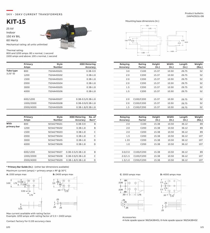
120 121
PrimaryAmps
Style Number
IEEE Metering Accuracy
Relaying Accuracy
Rating Factor
Height (in.)
Width (in.)
Length (in.)
Weight (lbs.)
Tube type3.25" ID
800 7524A45G01 0.3B-0.9 3.0 C100 15.37 10.50 26.75 52
1200 7524A45G02 0.3B-1.8 2.0 C200 15.37 10.50 26.75 52
1500 7524A45G03 0.3B-1.8 2.0 C200 15.37 10.50 26.75 52
2000 7524A45G04 0.3B-1.8 2.0 C200 15.37 10.50 26.75 52
3000 7524A45G05 0.3B-1.8 1.5 C200 15.37 10.50 26.75 52
4000 7524A45G06 0.3B-1.8 1.5 C200 15.37 10.50 26.75 52
600/1200 7524A45G07 0.3B-0.5/0.3B-1.8 2.0 C100/C200 15.37 10.50 26.75 52
1000/2000 7524A45G08 0.3B-0.9/0.3B-1.8 2.0 C100/C200 15.37 10.50 26.75 52
2000/4000 7524A45G09 0.3B-1.8/0.3B-1.8 1.5 C100/C200 15.37 10.50 26.75 52
2.13
4.258.25
4.00
3.25
5.75
7.00
4.88
9.75
2.007.00
PrimaryAmps
Style Number
IEEE Metering Accuracy
No. of Bars*
Relaying Accuracy
Rating Factor
Height (in.)
Width (in.)
Length (in.)
Weight (lbs.)
With primary bar
800 923A279G01 0.3B-0.9 B 2.0 C100 15.38 10.50 36.12 89
1200 923A279G02 0.3B-1.8 B 2.0 C200 15.38 10.50 36.12 89
1500 923A279G03 0.3B-1.8 C 2.0 C200 15.38 10.50 36.12 89
2000 923A279G04 0.3B-1.8 C 1.5 C200 15.38 10.50 36.12 107
3000 923A279G05 0.3B-1.8 D 1.33 C200 15.38 10.50 36.12 107
4000 923A279G06 0.3B-1.8 D 1.0 C200 15.38 10.50 36.12 107
600/1200 923A279G07 0.3B-0.5/0.3B-1.8 B 3.0/2.0 C100/C200 15.38 10.50 36.12 89
1000/2000 923A279G08 0.3B-0.9/0.3B-1.8 C 2.0/1.5 C100/C200 15.38 10.50 36.12 107
2000/4000 923A279G09 0.3B-1.8/0.3B-1.8 D 1.5/1.0 C200/C200 15.38 10.50 36.12 107
—5K V - 3 6 K V CU R R ENT TR A NS FO R M ER S
KIT-1525 kVIndoor150 kV BIL60 HertzMechanical rating: all units unlimited
Thermal rating:800 and 1200 amps: 80 x normal, 1 second1500 amps and above: 100 x normal, 1 second
Product bulletin:1VAP429151-DB
Mounting base dimensions (in.)
Contact factory for 0.15S accuracy class
3.00 1.75 0.88
0.50
1.75
0.25
0.88
1.75.50
.88.883.0
.25.25
.25
1.75
1.75
2.5
2.5
.50 1.75
.25
.25.25
.25.25
.50 1.75.88
.882.00
2.00
Max current available with rating factor. Example: 1200 amps with rating factor of 2.0 = 2400 amps
* Primary Bar Guide (in.) - (other bar dimensions available)
Maximum current (amps) = primary amps x RF @ 30°C
Accessories:4-hole spade spacer 9625A38H01; 6-hole spade spacer 9625A38H02
B: 2400 amps max D: 4000 amps maxA: 1550 amps max C: 3000 amps max
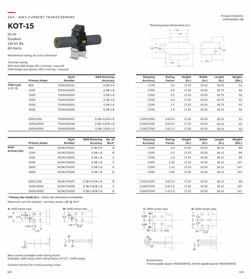
122 123
Primary AmpsStyle
NumberIEEE Metering
AccuracyNo. ofBars*
Relaying Accuracy
Rating Factor
Height (in.)
Width (in.)
Length (in.)
Weight (lbs.)
With primary bar
800 923A270G01 0.3B-0.9 B C100 2.0 17.25 10.50 36.12 89
1200 923A270G02 0.3B-1.8 B C200 2.0 17.25 10.50 36.12 89
1500 923A270G03 0.3B-1.8 C C200 2.0 17.25 10.50 36.12 89
2000 923A270G04 0.3B-1.8 C C200 1.50 17.25 10.50 36.12 107
3000 923A270G05 0.3B-1.8 D C200 1.33 17.25 10.50 36.12 107
4000 923A270G06 0.3B-1.8 D C200 1.00 17.25 10.50 36.12 107
600/1200 923A270G07 0.3B-0.5/B-1.8 B C100/C200 3.0/2.0 17.25 10.50 36.12 89
1000/2000 923A270G08 0.3B-0.9/B-1.8 C C100/C200 2.0/1.5 17.25 10.50 36.12 107
2000/4000 923A270G09 0.3B-1.8/B-1.8 D C100/C200 1.5/1.0 17.25 10.50 36.12 107
Primary AmpsStyle
NumberIEEE Metering
AccuracyRelaying Accuracy
Rating Factor
Height (in.)
Width (in.)
Length (in.)
Weight (lbs.)
Tube type3.25" ID
800 7524A35G01 0.3B-0.9 C100 2.0 17.25 10.50 26.75 52
1200 7524A35G02 0.3B-1.8 C200 2.0 17.25 10.50 26.75 52
1500 7524A35G03 0.3B-1.8 C200 2.0 17.25 10.50 26.75 52
2000 7524A35G04 0.3B-1.8 C200 2.0 17.25 10.50 26.75 52
3000 7524A35G05 0.3B-1.8 C200 1.5 17.25 10.50 26.75 52
4000 7524A35G06 0.3B-1.8 C200 1.5 17.25 10.50 26.75 52
600/1200 7524A35G07 0.3B-0.5/B-1.8 C100/C200 3.0/2.0 17.25 10.50 26.75 52
1000/2000 7524A35G08 0.3B-0.9/B-1.8 C100/C200 3.0/2.0 17.25 10.50 26.75 52
2000/4000 7524A35G09 0.3B-1.8/B-1.8 C100/C200 2.0/1.5 17.25 10.50 26.75 52
2.13
4.258.25
4.00
3.25
5.75
7.00
4.88
9.75
2.007.00
—5K V - 3 6 K V CU R R ENT TR A NS FO R M ER S
KOT-1525 kVOutdoor150 kV BIL60 Hertz
Mechanical rating: all units unlimited
Thermal rating:800 and 1200 Amps: 80 x normal, 1 second1500 Amps and above: 100 x normal, 1 second
Product bulletin:1VAP429301-DB
Mounting base dimensions (in.)
Contact factory for 0.15S accuracy class
3.00 1.75 0.88
0.50
1.75
0.25
0.88
1.75.50
.88.883.0
.25.25
.25
1.75
1.75
2.5
2.5
.50 1.75
.25
.25.25
.25.25
.50 1.75.88
.882.00
2.00
Max current available with rating factor. Example: 1200 amps with rating factor of 2.0 = 2400 amps
* Primary Bar Guide (in.) - (other bar dimensions available)
Maximum current (amps) = primary amps x RF @ 30°C
Accessories:4-hole spade spacer 9625A38H01; 6-hole spade spacer 9625A38H02
B: 2400 amps max D: 4000 amps maxA: 1550 amps max C: 3000 amps max
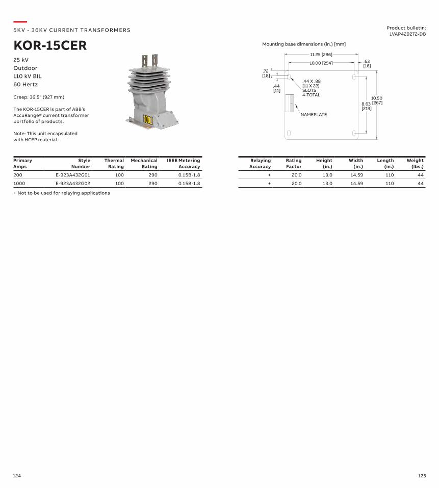
124 125
11.25 [286]
10.00 [254]
8.63 [219]
10.50 [267]
.44 [11]
.72 [18]
.63 [16]
.44 X .88[11 X 22]SLOTS4-TOTAL
NAMEPLATE
—5K V - 3 6 K V CU R R ENT TR A NS FO R M ER S
KOR-15CER25 kVOutdoor110 kV BIL60 Hertz
Mounting base dimensions (in.) [mm]
Product bulletin:1VAP429272-DB
Creep: 36.5" (927 mm)
The KOR-15CER is part of ABB’s AccuRange® current transformer portfolio of products.
Primary Amps
Style Number
Thermal Rating
Mechanical Rating
IEEE Metering Accuracy
Relaying Accuracy
Rating Factor
Height (in.)
Width (in.)
Length (in.)
Weight (lbs.)
200 E-923A432G01 100 290 0.15B-1.8 + 20.0 13.0 14.59 110 44
1000 E-923A432G02 100 290 0.15B-1.8 + 20.0 13.0 14.59 110 44
Note: This unit encapsulated with HCEP material.
+ Not to be used for relaying applications
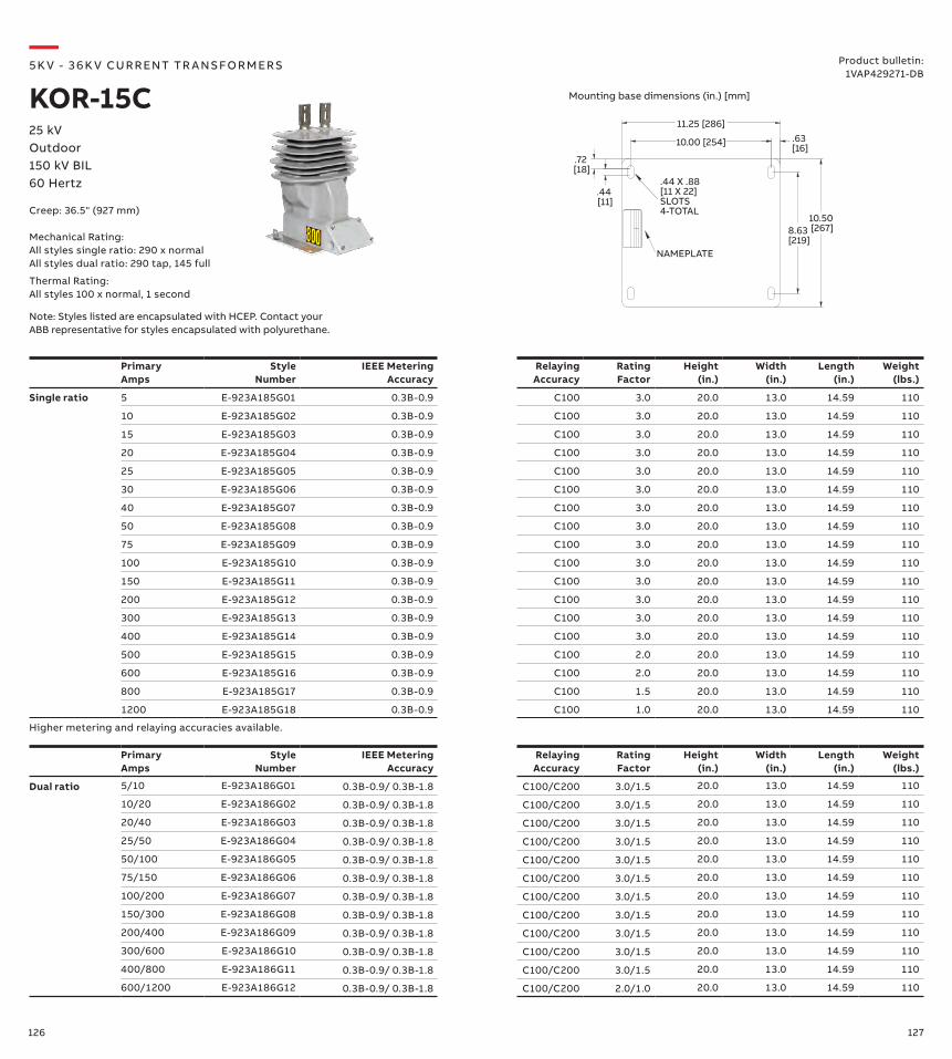
126 127
PrimaryAmps
Style Number
IEEE Metering Accuracy
Relaying Accuracy
Rating Factor
Height (in.)
Width (in.)
Length (in.)
Weight (lbs.)
Dual ratio 5/10 E-923A186G01 0.3B-0.9/ 0.3B-1.8 C100/C200 3.0/1.5 20.0 13.0 14.59 110
10/20 E-923A186G02 0.3B-0.9/ 0.3B-1.8 C100/C200 3.0/1.5 20.0 13.0 14.59 110
20/40 E-923A186G03 0.3B-0.9/ 0.3B-1.8 C100/C200 3.0/1.5 20.0 13.0 14.59 110
25/50 E-923A186G04 0.3B-0.9/ 0.3B-1.8 C100/C200 3.0/1.5 20.0 13.0 14.59 110
50/100 E-923A186G05 0.3B-0.9/ 0.3B-1.8 C100/C200 3.0/1.5 20.0 13.0 14.59 110
75/150 E-923A186G06 0.3B-0.9/ 0.3B-1.8 C100/C200 3.0/1.5 20.0 13.0 14.59 110
100/200 E-923A186G07 0.3B-0.9/ 0.3B-1.8 C100/C200 3.0/1.5 20.0 13.0 14.59 110
150/300 E-923A186G08 0.3B-0.9/ 0.3B-1.8 C100/C200 3.0/1.5 20.0 13.0 14.59 110
200/400 E-923A186G09 0.3B-0.9/ 0.3B-1.8 C100/C200 3.0/1.5 20.0 13.0 14.59 110
300/600 E-923A186G10 0.3B-0.9/ 0.3B-1.8 C100/C200 3.0/1.5 20.0 13.0 14.59 110
400/800 E-923A186G11 0.3B-0.9/ 0.3B-1.8 C100/C200 3.0/1.5 20.0 13.0 14.59 110
600/1200 E-923A186G12 0.3B-0.9/ 0.3B-1.8 C100/C200 2.0/1.0 20.0 13.0 14.59 110
PrimaryAmps
Style Number
IEEE Metering Accuracy
Relaying Accuracy
Rating Factor
Height (in.)
Width (in.)
Length (in.)
Weight (lbs.)
Single ratio 5 E-923A185G01 0.3B-0.9 C100 3.0 20.0 13.0 14.59 110
10 E-923A185G02 0.3B-0.9 C100 3.0 20.0 13.0 14.59 110
15 E-923A185G03 0.3B-0.9 C100 3.0 20.0 13.0 14.59 110
20 E-923A185G04 0.3B-0.9 C100 3.0 20.0 13.0 14.59 110
25 E-923A185G05 0.3B-0.9 C100 3.0 20.0 13.0 14.59 110
30 E-923A185G06 0.3B-0.9 C100 3.0 20.0 13.0 14.59 110
40 E-923A185G07 0.3B-0.9 C100 3.0 20.0 13.0 14.59 110
50 E-923A185G08 0.3B-0.9 C100 3.0 20.0 13.0 14.59 110
75 E-923A185G09 0.3B-0.9 C100 3.0 20.0 13.0 14.59 110
100 E-923A185G10 0.3B-0.9 C100 3.0 20.0 13.0 14.59 110
150 E-923A185G11 0.3B-0.9 C100 3.0 20.0 13.0 14.59 110
200 E-923A185G12 0.3B-0.9 C100 3.0 20.0 13.0 14.59 110
300 E-923A185G13 0.3B-0.9 C100 3.0 20.0 13.0 14.59 110
400 E-923A185G14 0.3B-0.9 C100 3.0 20.0 13.0 14.59 110
500 E-923A185G15 0.3B-0.9 C100 2.0 20.0 13.0 14.59 110
600 E-923A185G16 0.3B-0.9 C100 2.0 20.0 13.0 14.59 110
800 E-923A185G17 0.3B-0.9 C100 1.5 20.0 13.0 14.59 110
1200 E-923A185G18 0.3B-0.9 C100 1.0 20.0 13.0 14.59 110
11.25 [286]
10.00 [254]
8.63 [219]
10.50 [267]
.44 [11]
.72 [18]
.63 [16]
.44 X .88[11 X 22]SLOTS4-TOTAL
NAMEPLATE
Higher metering and relaying accuracies available.
—5K V - 3 6 K V CU R R ENT TR A NS FO R M ER S
KOR-15C25 kVOutdoor150 kV BIL60 Hertz
Product bulletin:1VAP429271-DB
Mechanical Rating:All styles single ratio: 290 x normal All styles dual ratio: 290 tap, 145 full
Thermal Rating:All styles 100 x normal, 1 second
Mounting base dimensions (in.) [mm]
Note: Styles listed are encapsulated with HCEP. Contact your ABB representative for styles encapsulated with polyurethane.
Creep: 36.5" (927 mm)
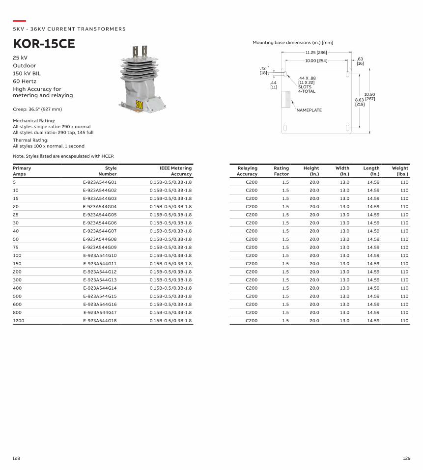
128 129
PrimaryAmps
Style Number
IEEE Metering Accuracy
Relaying Accuracy
Rating Factor
Height (in.)
Width (in.)
Length (in.)
Weight (lbs.)
5 E-923A544G01 0.15B-0.5/0.3B-1.8 C200 1.5 20.0 13.0 14.59 110
10 E-923A544G02 0.15B-0.5/0.3B-1.8 C200 1.5 20.0 13.0 14.59 110
15 E-923A544G03 0.15B-0.5/0.3B-1.8 C200 1.5 20.0 13.0 14.59 110
20 E-923A544G04 0.15B-0.5/0.3B-1.8 C200 1.5 20.0 13.0 14.59 110
25 E-923A544G05 0.15B-0.5/0.3B-1.8 C200 1.5 20.0 13.0 14.59 110
30 E-923A544G06 0.15B-0.5/0.3B-1.8 C200 1.5 20.0 13.0 14.59 110
40 E-923A544G07 0.15B-0.5/0.3B-1.8 C200 1.5 20.0 13.0 14.59 110
50 E-923A544G08 0.15B-0.5/0.3B-1.8 C200 1.5 20.0 13.0 14.59 110
75 E-923A544G09 0.15B-0.5/0.3B-1.8 C200 1.5 20.0 13.0 14.59 110
100 E-923A544G10 0.15B-0.5/0.3B-1.8 C200 1.5 20.0 13.0 14.59 110
150 E-923A544G11 0.15B-0.5/0.3B-1.8 C200 1.5 20.0 13.0 14.59 110
200 E-923A544G12 0.15B-0.5/0.3B-1.8 C200 1.5 20.0 13.0 14.59 110
300 E-923A544G13 0.15B-0.5/0.3B-1.8 C200 1.5 20.0 13.0 14.59 110
400 E-923A544G14 0.15B-0.5/0.3B-1.8 C200 1.5 20.0 13.0 14.59 110
500 E-923A544G15 0.15B-0.5/0.3B-1.8 C200 1.5 20.0 13.0 14.59 110
600 E-923A544G16 0.15B-0.5/0.3B-1.8 C200 1.5 20.0 13.0 14.59 110
800 E-923A544G17 0.15B-0.5/0.3B-1.8 C200 1.5 20.0 13.0 14.59 110
1200 E-923A544G18 0.15B-0.5/0.3B-1.8 C200 1.5 20.0 13.0 14.59 110
—5K V - 3 6 K V CU R R ENT TR A NS FO R M ER S
KOR-15CE25 kVOutdoor150 kV BIL60 HertzHigh Accuracy for metering and relaying
11.25 [286]
10.00 [254]
8.63 [219]
10.50 [267]
.44 [11]
.72 [18]
.63 [16]
.44 X .88[11 X 22]SLOTS4-TOTAL
NAMEPLATECreep: 36.5" (927 mm)
Mounting base dimensions (in.) [mm]
Mechanical Rating:All styles single ratio: 290 x normal All styles dual ratio: 290 tap, 145 full
Thermal Rating:All styles 100 x normal, 1 second
Note: Styles listed are encapsulated with HCEP.
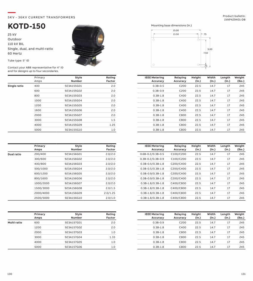
130 131
PrimaryAmps
Style Number
Rating Factor
IEEE Metering Accuracy
Relaying Accuracy
Height (in.)
Width (in.)
Length (in.)
Weight (lbs.)
Multi ratio 600 923A157G01 2.0 0.3B-0.9 C200 22.5 14.7 17 245
1200 923A157G02 2.0 0.3B-1.8 C400 22.5 14.7 17 245
2000 923A157G03 1.0 0.3B-1.8 C800 22.5 14.7 17 245
3000 923A157G04 1.33 0.3B-1.8 C800 22.5 14.7 17 245
4000 923A157G05 1.0 0.3B-1.8 C800 22.5 14.7 17 245
5000 923A157G06 1.0 0.3B-1.8 C800 22.5 14.7 17 245
PrimaryAmps
Style Number
Rating Factor
IEEE Metering Accuracy
Relaying Accuracy
Height (in.)
Width (in.)
Length (in.)
Weight (lbs.)
Dual ratio 200/400 923A156G01 2.0/2.0 0.6B-0.2/0.3B-0.5 C100/C200 22.5 14.7 17 245
300/600 923A156G02 2.0/2.0 0.3B-0.2/0.3B-0.9 C100/C200 22.5 14.7 17 245
400/800 923A156G03 2.0/2.0 0.3B-0.5/0.3B-1.8 C200/C400 22.5 14.7 17 245
500/1000 923A156G04 2.0/2.0 0.3B-0.5/0.3B-1.8 C200/C400 22.5 14.7 17 245
600/1200 923A156G05 2.0/2.0 0.3B-0.9/0.3B-1.8 C200/C400 22.5 14.7 17 245
800/1600 923A156G06 2.0/2.0 0.3B-0.9/0.3B-1.8 C200/C400 22.5 14.7 17 245
1000/2000 923A156G07 2.0/2.0 0.3B-1.8/0.3B-1.8 C400/C800 22.5 14.7 17 245
1500/3000 923A156G08 2.0/1.5 0.3B-1.8/0.3B-1.8 C400/C800 22.5 14.7 17 245
2000/4000 923A156G09 2.0/1.25 0.3B-1.8/0.3B-1.8 C400/C800 22.5 14.7 17 245
2500/5000 923A156G10 2.0/1.0 0.3B-1.8/0.3B-1.8 C400/C800 22.5 14.7 17 245
PrimaryAmps
Style Number
Rating Factor
IEEE Metering Accuracy
Relaying Accuracy
Height (in.)
Width (in.)
Length (in.)
Weight (lbs.)
Single ratio 400 923A155G01 2.0 0.3B-0.5 C200 22.5 14.7 17 245
600 923A155G02 2.0 0.3B-0.9 C200 22.5 14.7 17 245
800 923A155G03 2.0 0.3B-1.8 C400 22.5 14.7 17 245
1000 923A155G04 2.0 0.3B-1.8 C400 22.5 14.7 17 245
1200 923A155G05 2.0 0.3B-1.8 C400 22.5 14.7 17 245
1600 923A155G06 2.0 0.3B-1.8 C400 22.5 14.7 17 245
2000 923A155G07 2.0 0.3B-1.8 C800 22.5 14.7 17 245
3000 923A155G08 1.5 0.3B-1.8 C800 22.5 14.7 17 245
4000 923A155G09 1.25 0.3B-1.8 C800 22.5 14.7 17 245
5000 923A155G10 1.0 0.3B-1.8 C800 22.5 14.7 17 245
7.50
.75
9.00
13.50 .75
15.00
—5K V - 3 6 K V CU R R ENT TR A NS FO R M ER S
KOTD-150Product bulletin:
1VAP429401-DB
25 kVOutdoor110 kV BILSingle, dual, and multi-ratio60 Hertz
Mounting base dimensions (in.)
Tube type: 5" ID
Contact your ABB representative for 4" ID and for designs up to four secondaries.
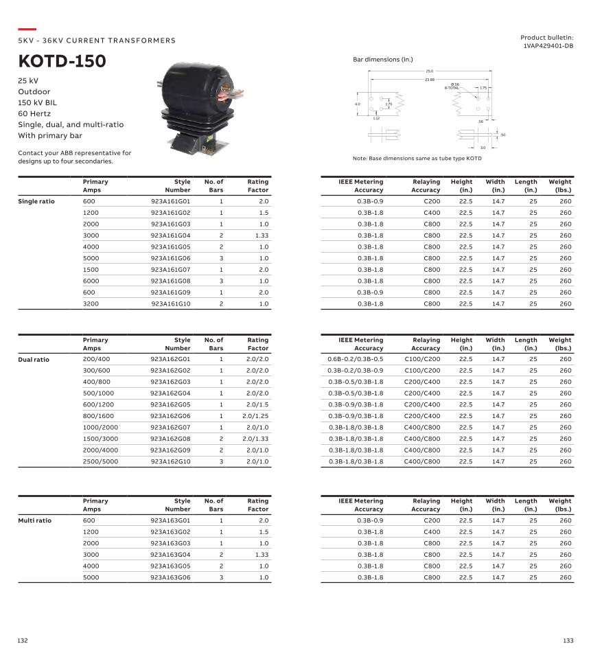
132 133
Primary Amps
Style Number
No. of Bars
Rating Factor
IEEE Metering Accuracy
Relaying Accuracy
Height (in.)
Width (in.)
Length (in.)
Weight (lbs.)
Multi ratio 600 923A163G01 1 2.0 0.3B-0.9 C200 22.5 14.7 25 260
1200 923A163G02 1 1.5 0.3B-1.8 C400 22.5 14.7 25 260
2000 923A163G03 1 1.0 0.3B-1.8 C800 22.5 14.7 25 260
3000 923A163G04 2 1.33 0.3B-1.8 C800 22.5 14.7 25 260
4000 923A163G05 2 1.0 0.3B-1.8 C800 22.5 14.7 25 260
5000 923A163G06 3 1.0 0.3B-1.8 C800 22.5 14.7 25 260
Primary Amps
Style Number
No. of Bars
Rating Factor
IEEE Metering Accuracy
Relaying Accuracy
Height (in.)
Width (in.)
Length (in.)
Weight (lbs.)
Dual ratio 200/400 923A162G01 1 2.0/2.0 0.6B-0.2/0.3B-0.5 C100/C200 22.5 14.7 25 260
300/600 923A162G02 1 2.0/2.0 0.3B-0.2/0.3B-0.9 C100/C200 22.5 14.7 25 260
400/800 923A162G03 1 2.0/2.0 0.3B-0.5/0.3B-1.8 C200/C400 22.5 14.7 25 260
500/1000 923A162G04 1 2.0/2.0 0.3B-0.5/0.3B-1.8 C200/C400 22.5 14.7 25 260
600/1200 923A162G05 1 2.0/1.5 0.3B-0.9/0.3B-1.8 C200/C400 22.5 14.7 25 260
800/1600 923A162G06 1 2.0/1.25 0.3B-0.9/0.3B-1.8 C200/C400 22.5 14.7 25 260
1000/2000 923A162G07 1 2.0/1.0 0.3B-1.8/0.3B-1.8 C400/C800 22.5 14.7 25 260
1500/3000 923A162G08 2 2.0/1.33 0.3B-1.8/0.3B-1.8 C400/C800 22.5 14.7 25 260
2000/4000 923A162G09 2 2.0/1.0 0.3B-1.8/0.3B-1.8 C400/C800 22.5 14.7 25 260
2500/5000 923A162G10 3 2.0/1.0 0.3B-1.8/0.3B-1.8 C400/C800 22.5 14.7 25 260
Primary Amps
Style Number
No. of Bars
Rating Factor
IEEE Metering Accuracy
Relaying Accuracy
Height (in.)
Width (in.)
Length (in.)
Weight (lbs.)
Single ratio 600 923A161G01 1 2.0 0.3B-0.9 C200 22.5 14.7 25 260
1200 923A161G02 1 1.5 0.3B-1.8 C400 22.5 14.7 25 260
2000 923A161G03 1 1.0 0.3B-1.8 C800 22.5 14.7 25 260
3000 923A161G04 2 1.33 0.3B-1.8 C800 22.5 14.7 25 260
4000 923A161G05 2 1.0 0.3B-1.8 C800 22.5 14.7 25 260
5000 923A161G06 3 1.0 0.3B-1.8 C800 22.5 14.7 25 260
1500 923A161G07 1 2.0 0.3B-1.8 C800 22.5 14.7 25 260
6000 923A161G08 3 1.0 0.3B-1.8 C800 22.5 14.7 25 260
600 923A161G09 1 2.0 0.3B-0.9 C800 22.5 14.7 25 260
3200 923A161G10 2 1.0 0.3B-1.8 C800 22.5 14.7 25 260
Note: Base dimensions same as tube type KOTD
25.0
4.0
1.12
1.75
1.75
23.88
.56
Ø.56 8-TOTAL
.50
3.0
—5K V - 3 6 K V CU R R ENT TR A NS FO R M ER S
KOTD-15025 kVOutdoor150 kV BIL60 HertzSingle, dual, and multi-ratioWith primary bar
Bar dimensions (in.)
Product bulletin:1VAP429401-DB
Contact your ABB representative for designs up to four secondaries.
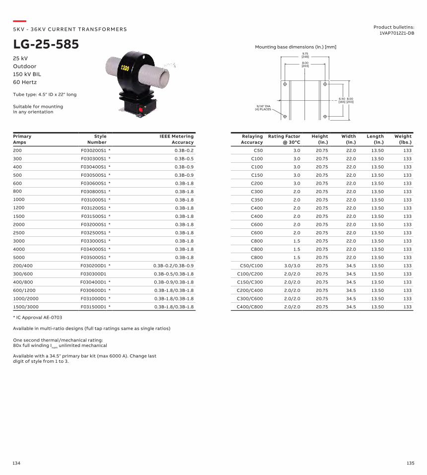
134 135
Primary Amps
Style Number
IEEE Metering Accuracy
Relaying Accuracy
Rating Factor @ 30°C
Height (in.)
Width (in.)
Length (in.)
Weight (lbs.)
200 F030200S1 * 0.3B-0.2 C50 3.0 20.75 22.0 13.50 133
300 F030300S1 * 0.3B-0.5 C100 3.0 20.75 22.0 13.50 133
400 F030400S1 * 0.3B-0.9 C100 3.0 20.75 22.0 13.50 133
500 F030500S1 * 0.3B-0.9 C150 3.0 20.75 22.0 13.50 133
600 F030600S1 * 0.3B-1.8 C200 3.0 20.75 22.0 13.50 133
800 F030800S1 * 0.3B-1.8 C300 2.0 20.75 22.0 13.50 133
1000 F031000S1 * 0.3B-1.8 C350 2.0 20.75 22.0 13.50 133
1200 F031200S1 * 0.3B-1.8 C400 2.0 20.75 22.0 13.50 133
1500 F031500S1 * 0.3B-1.8 C400 2.0 20.75 22.0 13.50 133
2000 F032000S1 * 0.3B-1.8 C600 2.0 20.75 22.0 13.50 133
2500 F032500S1 * 0.3B-1.8 C600 2.0 20.75 22.0 13.50 133
3000 F033000S1 * 0.3B-1.8 C800 1.5 20.75 22.0 13.50 133
4000 F034000S1 * 0.3B-1.8 C800 1.5 20.75 22.0 13.50 133
5000 F035000S1 * 0.3B-1.8 C800 1.5 20.75 22.0 13.50 133
200/400 F030200D1 * 0.3B-0.2/0.3B-0.9 C50/C100 3.0/3.0 20.75 34.5 13.50 133
300/600 F030300D1 0.3B-0.5/0.3B-1.8 C100/C200 2.0/2.0 20.75 34.5 13.50 133
400/800 F030400D1 * 0.3B-0.9/0.3B-1.8 C150/C300 2.0/2.0 20.75 34.5 13.50 133
600/1200 F030600D1 * 0.3B-1.8/0.3B-1.8 C200/C400 2.0/2.0 20.75 34.5 13.50 133
1000/2000 F031000D1 * 0.3B-1.8/0.3B-1.8 C300/C600 2.0/2.0 20.75 34.5 13.50 133
1500/3000 F031500D1 * 0.3B-1.8/0.3B-1.8 C400/C800 2.0/2.0 20.75 34.5 13.50 133
One second thermal/mechanical rating: 80x full winding Inom unlimited mechanical
* IC Approval AE-0703
Available with a 34.5" primary bar kit (max 6000 A). Change last digit of style from 1 to 3.
Available in multi-ratio designs (full tap ratings same as single ratios)
9.75[248]
9/16" DIA.(4) PLACES
8.00[203]
6.50[165]
8.00[203]
—5K V - 3 6 K V CU R R ENT TR A NS FO R M ER S
LG-25-58525 kVOutdoor150 kV BIL60 Hertz
Product bulletins: 1VAP701221-DB
Mounting base dimensions (in.) [mm]
Suitable for mounting in any orientation
Tube type: 4.5" ID x 22" long
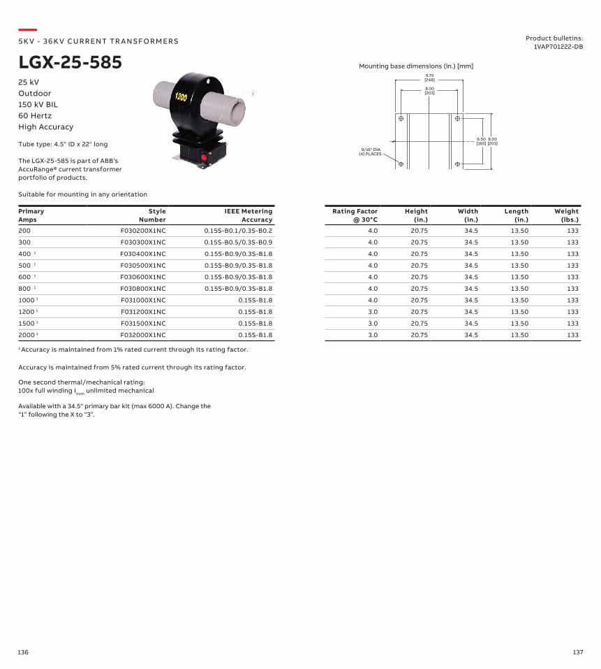
136 137
9.75[248]
9/16" DIA.(4) PLACES
8.00[203]
6.50[165]
8.00[203]
—5K V - 3 6 K V CU R R ENT TR A NS FO R M ER S
LGX-25-58525 kVOutdoor150 kV BIL60 HertzHigh Accuracy
Product bulletins:1VAP701222-DB
Mounting base dimensions (in.) [mm]
Suitable for mounting in any orientation
Primary Amps
Style Number
IEEE Metering Accuracy
Rating Factor @ 30°C
Height (in.)
Width (in.)
Length (in.)
Weight (lbs.)
200 F030200X1NC 0.15S-B0.1/0.3S-B0.2 4.0 20.75 34.5 13.50 133
300 F030300X1NC 0.15S-B0.5/0.3S-B0.9 4.0 20.75 34.5 13.50 133
400 1 F030400X1NC 0.15S-B0.9/0.3S-B1.8 4.0 20.75 34.5 13.50 133
500 1 F030500X1NC 0.15S-B0.9/0.3S-B1.8 4.0 20.75 34.5 13.50 133
600 1 F030600X1NC 0.15S-B0.9/0.3S-B1.8 4.0 20.75 34.5 13.50 133
800 1 F030800X1NC 0.15S-B0.9/0.3S-B1.8 4.0 20.75 34.5 13.50 133
1000 1 F031000X1NC 0.15S-B1.8 4.0 20.75 34.5 13.50 133
1200 1 F031200X1NC 0.15S-B1.8 3.0 20.75 34.5 13.50 133
1500 1 F031500X1NC 0.15S-B1.8 3.0 20.75 34.5 13.50 133
2000 1 F032000X1NC 0.15S-B1.8 3.0 20.75 34.5 13.50 133
One second thermal/mechanical rating: 100x full winding Inom unlimited mechanical
Accuracy is maintained from 5% rated current through its rating factor.
1 Accuracy is maintained from 1% rated current through its rating factor.
Available with a 34.5" primary bar kit (max 6000 A). Change the “1” following the X to “3”.
Tube type: 4.5" ID x 22" long
The LGX-25-585 is part of ABB’s AccuRange® current transformer portfolio of products.
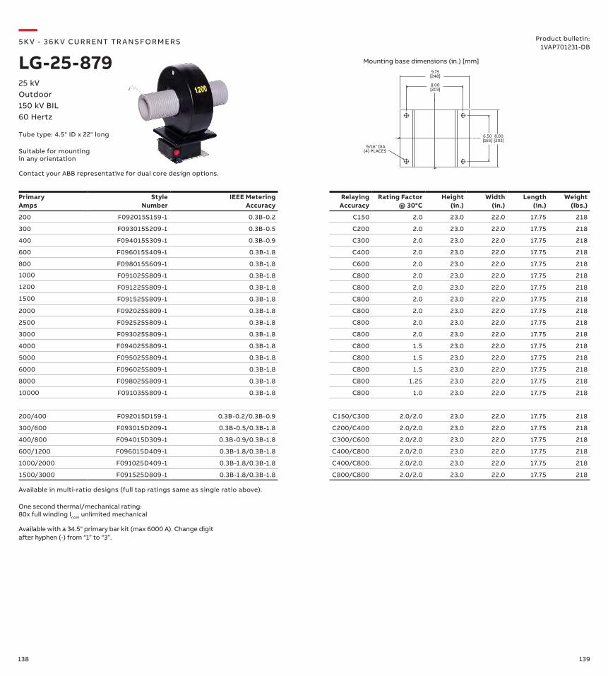
138 139
Primary Amps
Style Number
IEEE Metering Accuracy
Relaying Accuracy
Rating Factor @ 30°C
Height (in.)
Width (in.)
Length (in.)
Weight (lbs.)
200 F092015S159-1 0.3B-0.2 C150 2.0 23.0 22.0 17.75 218
300 F093015S209-1 0.3B-0.5 C200 2.0 23.0 22.0 17.75 218
400 F094015S309-1 0.3B-0.9 C300 2.0 23.0 22.0 17.75 218
600 F096015S409-1 0.3B-1.8 C400 2.0 23.0 22.0 17.75 218
800 F098015S609-1 0.3B-1.8 C600 2.0 23.0 22.0 17.75 218
1000 F091025S809-1 0.3B-1.8 C800 2.0 23.0 22.0 17.75 218
1200 F091225S809-1 0.3B-1.8 C800 2.0 23.0 22.0 17.75 218
1500 F091525S809-1 0.3B-1.8 C800 2.0 23.0 22.0 17.75 218
2000 F092025S809-1 0.3B-1.8 C800 2.0 23.0 22.0 17.75 218
2500 F092525S809-1 0.3B-1.8 C800 2.0 23.0 22.0 17.75 218
3000 F093025S809-1 0.3B-1.8 C800 2.0 23.0 22.0 17.75 218
4000 F094025S809-1 0.3B-1.8 C800 1.5 23.0 22.0 17.75 218
5000 F095025S809-1 0.3B-1.8 C800 1.5 23.0 22.0 17.75 218
6000 F096025S809-1 0.3B-1.8 C800 1.5 23.0 22.0 17.75 218
8000 F098025S809-1 0.3B-1.8 C800 1.25 23.0 22.0 17.75 218
10000 F091035S809-1 0.3B-1.8 C800 1.0 23.0 22.0 17.75 218
200/400 F092015D159-1 0.3B-0.2/0.3B-0.9 C150/C300 2.0/2.0 23.0 22.0 17.75 218
300/600 F093015D209-1 0.3B-0.5/0.3B-1.8 C200/C400 2.0/2.0 23.0 22.0 17.75 218
400/800 F094015D309-1 0.3B-0.9/0.3B-1.8 C300/C600 2.0/2.0 23.0 22.0 17.75 218
600/1200 F096015D409-1 0.3B-1.8/0.3B-1.8 C400/C800 2.0/2.0 23.0 22.0 17.75 218
1000/2000 F091025D409-1 0.3B-1.8/0.3B-1.8 C400/C800 2.0/2.0 23.0 22.0 17.75 218
1500/3000 F091525D809-1 0.3B-1.8/0.3B-1.8 C800/C800 2.0/2.0 23.0 22.0 17.75 218
One second thermal/mechanical rating: 80x full winding Inom unlimited mechanical
Available in multi-ratio designs (full tap ratings same as single ratio above).
Available with a 34.5" primary bar kit (max 6000 A). Change digit after hyphen (-) from “1” to “3”.
9.75[248]
9/16" DIA.(4) PLACES
8.00[203]
6.50[165]
8.00[203]
—5K V - 3 6 K V CU R R ENT TR A NS FO R M ER S
LG-25-879Product bulletin:
1VAP701231-DB
25 kVOutdoor150 kV BIL60 Hertz
Mounting base dimensions (in.) [mm]
Contact your ABB representative for dual core design options.
Suitable for mounting in any orientation
Tube type: 4.5" ID x 22" long
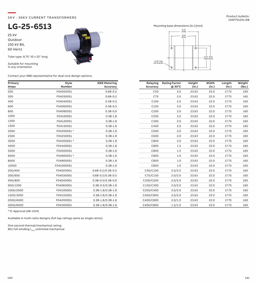
140 141
Primary Amps
Style Number
IEEE Metering Accuracy
Relaying Accuracy
Rating Factor @ 30°C
Height (in.)
Width (in.)
Length (in.)
Weight (lbs.)
200 F040200S1 0.6B-0.2 C50 2.0 23.63 22.0 17.75 160
300 F040300S1 0.6B-0.2 C75 2.0 23.63 22.0 17.75 160
400 F040400S1 0.3B-0.5 C100 2.0 23.63 22.0 17.75 160
600 F040600S1 0.3B-0.5 C150 2.0 23.63 22.0 17.75 160
800 F040800S1 0.3B-0.9 C200 2.0 23.63 22.0 17.75 160
1000 F041000S1 0.3B-1.8 C250 2.0 23.63 22.0 17.75 160
1200 F041200S1 0.3B-1.8 C300 2.0 23.63 22.0 17.75 160
1500 F041500S1 0.3B-1.8 C400 2.0 23.63 22.0 17.75 160
2000 F042000S1 * 0.3B-1.8 C500 2.0 23.63 22.0 17.75 160
2500 F042500S1 0.3B-1.8 C600 2.0 23.63 22.0 17.75 160
3000 F043000S1 * 0.3B-1.8 C800 2.0 23.63 22.0 17.75 160
4000 F044000S1 0.3B-1.8 C800 1.5 23.63 22.0 17.75 160
5000 F045000S1 0.3B-1.8 C800 1.5 23.63 22.0 17.75 160
6000 F046000S1 * 0.3B-1.8 C800 1.0 23.63 22.0 17.75 160
8000 F048000S1 0.3B-1.8 C800 1.0 23.63 22.0 17.75 160
10000 F0410000S1 0.3B-1.8 C800 1.0 23.63 22.0 17.75 160
200/400 F040200D1 0.6B-0.2/0.3B-0.5 C50/C100 2.0/2.0 23.63 22.0 17.75 160
300/600 F040300D1 0.6B-0.2/0.3B-0.5 C75/C150 2.0/2.0 23.63 22.0 17.75 160
400/800 F040400D1 0.3B-0.5/0.3B-0.9 C100/C200 2.0/2.0 23.63 22.0 17.75 160
600/1200 F040600D1 0.3B-0.5/0.3B-1.8 C150/C300 2.0/2.0 23.63 22.0 17.75 160
1000/2000 F041000D1 0.3B-1.8/0.3B-1.8 C200/C400 2.0/2.0 23.63 22.0 17.75 160
1500/3000 F041500D1 0.3B-1.8/0.3B-1.8 C400/C800 2.0/2.0 23.63 22.0 17.75 160
2000/4000 F042000D1 0.3B-1.8/0.3B-1.8 C400/C800 2.0/1.5 23.63 22.0 17.75 160
3000/6000 F043000D1 0.3B-1.8/0.3B-1.8 C400/C800 1.5/1.0 23.63 22.0 17.75 160
* IC Approval (AE-1104)
One second thermal/mechanical rating: 80x full winding Inom unlimited mechanical
Available in multi-ratio designs (full tap ratings same as single ratios)
9.75[248]
9/16" DIA.(4) PLACES
8.00[203]
6.50[165]
8.00[203]
—5K V - 3 6 K V CU R R ENT TR A NS FO R M ER S
LG-25-651325 kVOutdoor150 kV BIL60 Hertz
Product bulletin:1VAP701241-DB
Tube type: 8.75" ID x 22" long
Mounting base dimensions (in.) [mm]
Contact your ABB representative for dual core design options.
Suitable for mounting in any orientation
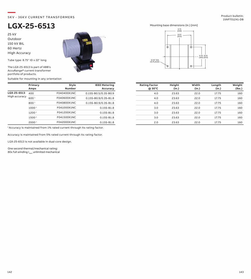
142 143
9.75[248]
9/16" DIA.(4) PLACES
8.00[203]
6.50[165]
8.00[203]
—5K V - 3 6 K V CU R R ENT TR A NS FO R M ER S
LGX-25-651325 kVOutdoor150 kV BIL60 HertzHigh Accuracy
Tube type: 8.75" ID x 22" long
Mounting base dimensions (in.) [mm]
Suitable for mounting in any orientation
Primary Amps
Style Number
IEEE Metering Accuracy
Rating Factor @ 30°C
Height (in.)
Width (in.)
Length (in.)
Weight(lbs.)
LGX-25-6513High accuracy
400 F040400X1NC 0.15S-B0.5/0.3S-B0.9 4.0 23.63 22.0 17.75 160
600 1 F040600X1NC 0.15S-B0.9/0.3S-B1.8 4.0 23.63 22.0 17.75 160
800 1 F040800X1NC 0.15S-B0.9/0.3S-B1.8 4.0 23.63 22.0 17.75 160
1000 1 F041000X1NC 0.15S-B1.8 3.0 23.63 22.0 17.75 160
1200 1 F041200X1NC 0.15S-B1.8 3.0 23.63 22.0 17.75 160
1500 1 F041500X1NC 0.15S-B1.8 3.0 23.63 22.0 17.75 160
2000 1 F042000X1NC 0.15S-B1.8 2.0 23.63 22.0 17.75 160
Accuracy is maintained from 5% rated current through its rating factor.
One second thermal/mechanical rating: 80x full winding Inom unlimited mechanical
LGX-25-6513 is not available in dual-core design.
1 Accuracy is maintained from 1% rated current through its rating factor.
Product bulletin:1VAP701241-DB
The LGX-25-6513 is part of ABB’s AccuRange® current transformer portfolio of products.

144 145
11.25 [286]
10.00 [254]
8.63 [219]
10.50 [267]
.44 [11]
.72 [18]
.63 [16]
.44 X .88[11 X 22]SLOTS4-TOTAL
NAMEPLATE
—5K V - 3 6 K V CU R R ENT TR A NS FO R M ER S
KOR-20ER34.5 kVOutdoor200 kV BIL60 Hertz
Product bulletin:1VAP429283-DB
Creep: 36.5" (927 mm)
Mounting base dimensions (in.) [mm]
Note: This unit encapsulated with HCEP material only.
Primary Amps
Style Number
Thermal Rating
Mechanical Rating
IEEE Metering Accuracy
Relaying Accuracy
Rating Factor
Height (in.)
Width (in.)
Length (in.)
Weight (lbs.)
200 E-923A433G01 100 290 0.15B-1.8 + 1.5 20.0 13.0 14.59 110
1000 E-923A433G02 100 290 0.15B-1.8 + 1.5 20.0 13.0 14.59 110
+ Not to be used for relaying applications
The KOR-20ER is part of ABB’s AccuRange® current transformer portfolio of products.
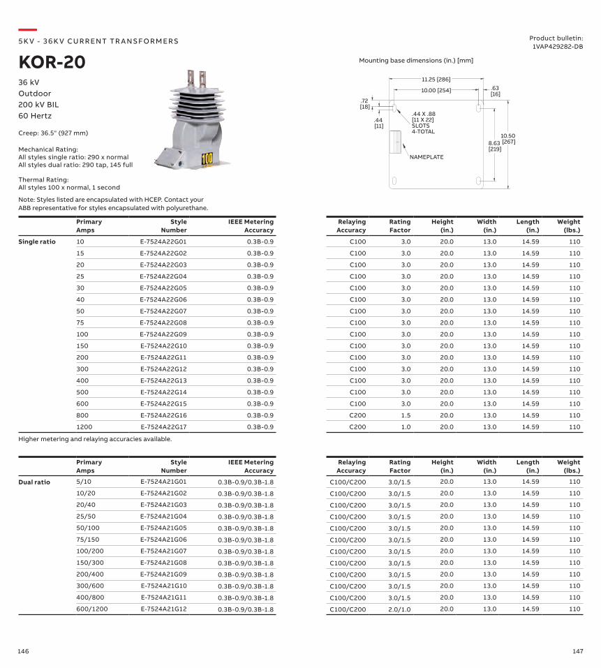
146 147
PrimaryAmps
Style Number
IEEE Metering Accuracy
Relaying Accuracy
Rating Factor
Height (in.)
Width (in.)
Length (in.)
Weight (lbs.)
Single ratio 10 E-7524A22G01 0.3B-0.9 C100 3.0 20.0 13.0 14.59 110
15 E-7524A22G02 0.3B-0.9 C100 3.0 20.0 13.0 14.59 110
20 E-7524A22G03 0.3B-0.9 C100 3.0 20.0 13.0 14.59 110
25 E-7524A22G04 0.3B-0.9 C100 3.0 20.0 13.0 14.59 110
30 E-7524A22G05 0.3B-0.9 C100 3.0 20.0 13.0 14.59 110
40 E-7524A22G06 0.3B-0.9 C100 3.0 20.0 13.0 14.59 110
50 E-7524A22G07 0.3B-0.9 C100 3.0 20.0 13.0 14.59 110
75 E-7524A22G08 0.3B-0.9 C100 3.0 20.0 13.0 14.59 110
100 E-7524A22G09 0.3B-0.9 C100 3.0 20.0 13.0 14.59 110
150 E-7524A22G10 0.3B-0.9 C100 3.0 20.0 13.0 14.59 110
200 E-7524A22G11 0.3B-0.9 C100 3.0 20.0 13.0 14.59 110
300 E-7524A22G12 0.3B-0.9 C100 3.0 20.0 13.0 14.59 110
400 E-7524A22G13 0.3B-0.9 C100 3.0 20.0 13.0 14.59 110
500 E-7524A22G14 0.3B-0.9 C100 3.0 20.0 13.0 14.59 110
600 E-7524A22G15 0.3B-0.9 C100 3.0 20.0 13.0 14.59 110
800 E-7524A22G16 0.3B-0.9 C200 1.5 20.0 13.0 14.59 110
1200 E-7524A22G17 0.3B-0.9 C200 1.0 20.0 13.0 14.59 110
11.25 [286]
10.00 [254]
8.63 [219]
10.50 [267]
.44 [11]
.72 [18]
.63 [16]
.44 X .88[11 X 22]SLOTS4-TOTAL
NAMEPLATE
Primary Amps
Style Number
IEEE Metering Accuracy
Relaying Accuracy
Rating Factor
Height (in.)
Width (in.)
Length (in.)
Weight (lbs.)
Dual ratio 5/10 E-7524A21G01 0.3B-0.9/0.3B-1.8 C100/C200 3.0/1.5 20.0 13.0 14.59 110
10/20 E-7524A21G02 0.3B-0.9/0.3B-1.8 C100/C200 3.0/1.5 20.0 13.0 14.59 110
20/40 E-7524A21G03 0.3B-0.9/0.3B-1.8 C100/C200 3.0/1.5 20.0 13.0 14.59 110
25/50 E-7524A21G04 0.3B-0.9/0.3B-1.8 C100/C200 3.0/1.5 20.0 13.0 14.59 110
50/100 E-7524A21G05 0.3B-0.9/0.3B-1.8 C100/C200 3.0/1.5 20.0 13.0 14.59 110
75/150 E-7524A21G06 0.3B-0.9/0.3B-1.8 C100/C200 3.0/1.5 20.0 13.0 14.59 110
100/200 E-7524A21G07 0.3B-0.9/0.3B-1.8 C100/C200 3.0/1.5 20.0 13.0 14.59 110
150/300 E-7524A21G08 0.3B-0.9/0.3B-1.8 C100/C200 3.0/1.5 20.0 13.0 14.59 110
200/400 E-7524A21G09 0.3B-0.9/0.3B-1.8 C100/C200 3.0/1.5 20.0 13.0 14.59 110
300/600 E-7524A21G10 0.3B-0.9/0.3B-1.8 C100/C200 3.0/1.5 20.0 13.0 14.59 110
400/800 E-7524A21G11 0.3B-0.9/0.3B-1.8 C100/C200 3.0/1.5 20.0 13.0 14.59 110
600/1200 E-7524A21G12 0.3B-0.9/0.3B-1.8 C100/C200 2.0/1.0 20.0 13.0 14.59 110
Higher metering and relaying accuracies available.
36 kVOutdoor200 kV BIL60 Hertz
Product bulletin:1VAP429282-DB
—5K V - 3 6 K V CU R R ENT TR A NS FO R M ER S
KOR-20
Creep: 36.5" (927 mm)
Mounting base dimensions (in.) [mm]
Note: Styles listed are encapsulated with HCEP. Contact your ABB representative for styles encapsulated with polyurethane.
Mechanical Rating:All styles single ratio: 290 x normal All styles dual ratio: 290 tap, 145 full
Thermal Rating:All styles 100 x normal, 1 second
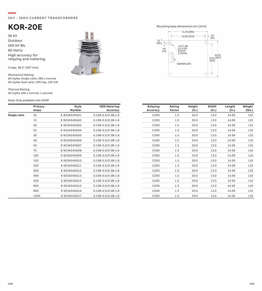
148 149
PrimaryAmps
Style Number
IEEE MeteringAccuracy
Relaying Accuracy
Rating Factor
Height (in.)
Width (in.)
Length (in.)
Weight (lbs.)
Single ratio 10 E-923A545G01 0.15B-0.5/0.3B-1.8 C200 1.5 20.0 13.0 14.59 110
15 E-923A545G02 0.15B-0.5/0.3B-1.8 C200 1.5 20.0 13.0 14.59 110
20 E-923A545G03 0.15B-0.5/0.3B-1.8 C200 1.5 20.0 13.0 14.59 110
25 E-923A545G04 0.15B-0.5/0.3B-1.8 C200 1.5 20.0 13.0 14.59 110
30 E-923A545G05 0.15B-0.5/0.3B-1.8 C200 1.5 20.0 13.0 14.59 110
40 E-923A545G06 0.15B-0.5/0.3B-1.8 C200 1.5 20.0 13.0 14.59 110
50 E-923A545G07 0.15B-0.5/0.3B-1.8 C200 1.5 20.0 13.0 14.59 110
75 E-923A545G08 0.15B-0.5/0.3B-1.8 C200 1.5 20.0 13.0 14.59 110
100 E-923A545G09 0.15B-0.5/0.3B-1.8 C200 1.5 20.0 13.0 14.59 110
150 E-923A545G10 0.15B-0.5/0.3B-1.8 C200 1.5 20.0 13.0 14.59 110
200 E-923A545G11 0.15B-0.5/0.3B-1.8 C200 1.5 20.0 13.0 14.59 110
300 E-923A545G12 0.15B-0.5/0.3B-1.8 C200 1.5 20.0 13.0 14.59 110
400 E-923A545G13 0.15B-0.5/0.3B-1.8 C200 1.5 20.0 13.0 14.59 110
500 E-923A545G14 0.15B-0.5/0.3B-1.8 C200 1.5 20.0 13.0 14.59 110
600 E-923A545G15 0.15B-0.5/0.3B-1.8 C200 1.5 20.0 13.0 14.59 110
800 E-923A545G16 0.15B-0.5/0.3B-1.8 C200 1.5 20.0 13.0 14.59 110
1200 E-923A545G17 0.15B-0.5/0.3B-1.8 C200 1.5 20.0 13.0 14.59 110
11.25 [286]
10.00 [254]
8.63 [219]
10.50 [267]
.44 [11]
.72 [18]
.63 [16]
.44 X .88[11 X 22]SLOTS4-TOTAL
NAMEPLATE
36 kVOutdoor200 kV BIL60 HertzHigh accuracy for relaying and metering
—5K V - 3 6 K V CU R R ENT TR A NS FO R M ER S
KOR-20E
Creep: 36.5" (927 mm)
Mechanical Rating:All styles single ratio: 290 x normal All styles dual ratio: 290 tap, 145 full
Thermal Rating:All styles 100 x normal, 1 second
Note: Only available with HCEP
Mounting base dimensions (in.) [mm]
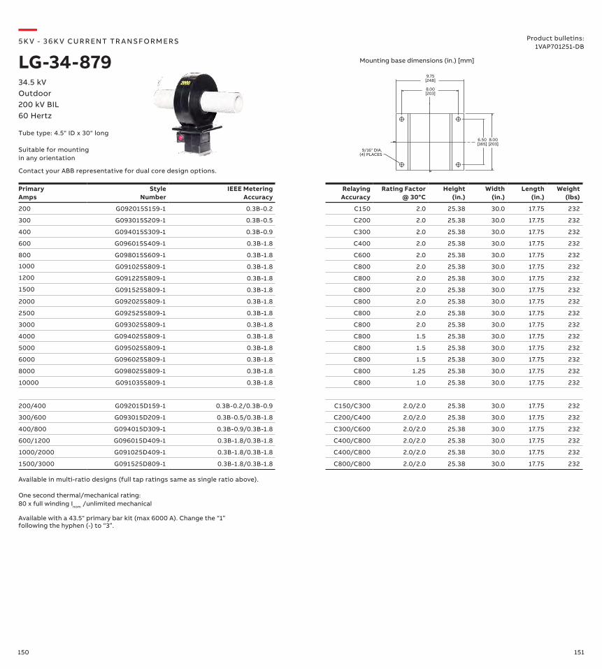
150 151
Primary Amps
Style Number
IEEE Metering Accuracy
Relaying Accuracy
Rating Factor @ 30°C
Height (in.)
Width (in.)
Length (in.)
Weight (lbs)
200 G092015S159-1 0.3B-0.2 C150 2.0 25.38 30.0 17.75 232
300 G093015S209-1 0.3B-0.5 C200 2.0 25.38 30.0 17.75 232
400 G094015S309-1 0.3B-0.9 C300 2.0 25.38 30.0 17.75 232
600 G096015S409-1 0.3B-1.8 C400 2.0 25.38 30.0 17.75 232
800 G098015S609-1 0.3B-1.8 C600 2.0 25.38 30.0 17.75 232
1000 G091025S809-1 0.3B-1.8 C800 2.0 25.38 30.0 17.75 232
1200 G091225S809-1 0.3B-1.8 C800 2.0 25.38 30.0 17.75 232
1500 G091525S809-1 0.3B-1.8 C800 2.0 25.38 30.0 17.75 232
2000 G092025S809-1 0.3B-1.8 C800 2.0 25.38 30.0 17.75 232
2500 G092525S809-1 0.3B-1.8 C800 2.0 25.38 30.0 17.75 232
3000 G093025S809-1 0.3B-1.8 C800 2.0 25.38 30.0 17.75 232
4000 G094025S809-1 0.3B-1.8 C800 1.5 25.38 30.0 17.75 232
5000 G095025S809-1 0.3B-1.8 C800 1.5 25.38 30.0 17.75 232
6000 G096025S809-1 0.3B-1.8 C800 1.5 25.38 30.0 17.75 232
8000 G098025S809-1 0.3B-1.8 C800 1.25 25.38 30.0 17.75 232
10000 G091035S809-1 0.3B-1.8 C800 1.0 25.38 30.0 17.75 232
200/400 G092015D159-1 0.3B-0.2/0.3B-0.9 C150/C300 2.0/2.0 25.38 30.0 17.75 232
300/600 G093015D209-1 0.3B-0.5/0.3B-1.8 C200/C400 2.0/2.0 25.38 30.0 17.75 232
400/800 G094015D309-1 0.3B-0.9/0.3B-1.8 C300/C600 2.0/2.0 25.38 30.0 17.75 232
600/1200 G096015D409-1 0.3B-1.8/0.3B-1.8 C400/C800 2.0/2.0 25.38 30.0 17.75 232
1000/2000 G091025D409-1 0.3B-1.8/0.3B-1.8 C400/C800 2.0/2.0 25.38 30.0 17.75 232
1500/3000 G091525D809-1 0.3B-1.8/0.3B-1.8 C800/C800 2.0/2.0 25.38 30.0 17.75 232
Available in multi-ratio designs (full tap ratings same as single ratio above).
One second thermal/mechanical rating: 80 x full winding Inom /unlimited mechanical
9.75[248]
9/16" DIA.(4) PLACES
8.00[203]
6.50[165]
8.00[203]
Available with a 43.5" primary bar kit (max 6000 A). Change the “1” following the hyphen (-) to “3”.
—5K V - 3 6 K V CU R R ENT TR A NS FO R M ER S
LG-34-87934.5 kVOutdoor200 kV BIL60 Hertz
Product bulletins: 1VAP701251-DB
Tube type: 4.5" ID x 30" long
Mounting base dimensions (in.) [mm]
Contact your ABB representative for dual core design options.
Suitable for mounting in any orientation
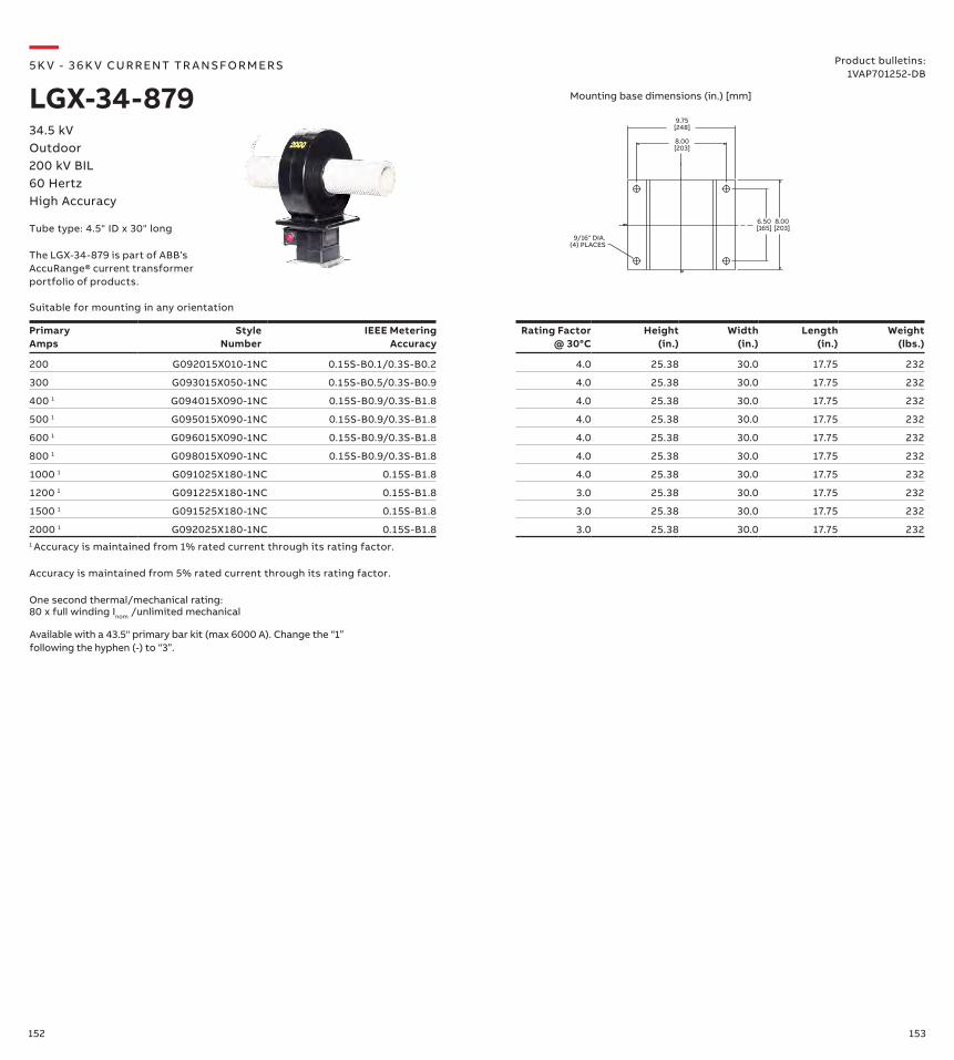
152 153
9.75[248]
9/16" DIA.(4) PLACES
8.00[203]
6.50[165]
8.00[203]
—5K V - 3 6 K V CU R R ENT TR A NS FO R M ER S
LGX-34-87934.5 kVOutdoor200 kV BIL60 HertzHigh Accuracy
Product bulletins: 1VAP701252-DB
Suitable for mounting in any orientation
Mounting base dimensions (in.) [mm]
Primary Amps
Style Number
IEEE Metering Accuracy
Rating Factor @ 30°C
Height (in.)
Width (in.)
Length (in.)
Weight (lbs.)
200 G092015X010-1NC 0.15S-B0.1/0.3S-B0.2 4.0 25.38 30.0 17.75 232
300 G093015X050-1NC 0.15S-B0.5/0.3S-B0.9 4.0 25.38 30.0 17.75 232
400 1 G094015X090-1NC 0.15S-B0.9/0.3S-B1.8 4.0 25.38 30.0 17.75 232
500 1 G095015X090-1NC 0.15S-B0.9/0.3S-B1.8 4.0 25.38 30.0 17.75 232
600 1 G096015X090-1NC 0.15S-B0.9/0.3S-B1.8 4.0 25.38 30.0 17.75 232
800 1 G098015X090-1NC 0.15S-B0.9/0.3S-B1.8 4.0 25.38 30.0 17.75 232
1000 1 G091025X180-1NC 0.15S-B1.8 4.0 25.38 30.0 17.75 232
1200 1 G091225X180-1NC 0.15S-B1.8 3.0 25.38 30.0 17.75 232
1500 1 G091525X180-1NC 0.15S-B1.8 3.0 25.38 30.0 17.75 232
2000 1 G092025X180-1NC 0.15S-B1.8 3.0 25.38 30.0 17.75 232
Accuracy is maintained from 5% rated current through its rating factor.
1 Accuracy is maintained from 1% rated current through its rating factor.
One second thermal/mechanical rating: 80 x full winding Inom /unlimited mechanical
Available with a 43.5" primary bar kit (max 6000 A). Change the “1” following the hyphen (-) to “3”.
Tube type: 4.5" ID x 30" long
The LGX-34-879 is part of ABB’s AccuRange® current transformer portfolio of products.
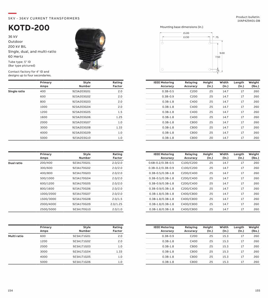
154 155
PrimaryAmps
Style Number
Rating Factor
IEEE Metering Accuracy
Relaying Accuracy
Height (in.)
Width (in.)
Length (in.)
Weight (lbs.)
Multi ratio 600 923A171G01 2.0 0.3B-0.9 C200 25 15.3 17 260
1200 923A171G02 2.0 0.3B-1.8 C400 25 15.3 17 260
2000 923A171G03 1.0 0.3B-1.8 C800 25 15.3 17 260
3000 923A171G04 1.33 0.3B-1.8 C800 25 15.3 17 260
4000 923A171G05 1.0 0.3B-1.8 C800 25 15.3 17 260
5000 923A171G06 1.0 0.3B-1.8 C800 25 15.3 17 260
PrimaryAmps
Style Number
Rating Factor
IEEE Metering Accuracy
Relaying Accuracy
Height (in.)
Width (in.)
Length (in.)
Weight (lbs.)
Dual ratio 200/400 923A170G01 2.0/2.0 0.6B-0.2/0.3B-0.5 C100/C200 25 14.7 17 260
300/600 923A170G02 2.0/2.0 0.3B-0.2/0.3B-0.9 C100/C200 25 14.7 17 260
400/800 923A170G03 2.0/2.0 0.3B-0.5/0.3B-1.8 C200/C400 25 14.7 17 260
500/1000 923A170G04 2.0/2.0 0.3B-0.5/0.3B-1.8 C200/C400 25 14.7 17 260
600/1200 923A170G05 2.0/2.0 0.3B-0.9/0.3B-1.8 C200/C400 25 14.7 17 260
800/1600 923A170G06 2.0/2.0 0.3B-0.9/0.3B-1.8 C200/C400 25 14.7 17 260
1000/2000 923A170G07 2.0/2.0 0.3B-1.8/0.3B-1.8 C400/C800 25 14.7 17 260
1500/3000 923A170G08 2.0/1.5 0.3B-1.8/0.3B-1.8 C400/C800 25 14.7 17 260
2000/4000 923A170G09 2.0/1.25 0.3B-1.8/0.3B-1.8 C400/C800 25 14.7 17 260
2500/5000 923A170G10 2.0/1.0 0.3B-1.8/0.3B-1.8 C400/C800 25 14.7 17 260
PrimaryAmps
Style Number
Rating Factor
IEEE Metering Accuracy
Relaying Accuracy
Height (in.)
Width (in.)
Length (in.)
Weight (lbs.)
Single ratio 400 923A203G01 2.0 0.3B-0.5 C200 25 14.7 17 260
600 923A203G02 2.0 0.3B-0.9 C200 25 14.7 17 260
800 923A203G03 2.0 0.3B-1.8 C400 25 14.7 17 260
1000 923A203G04 2.0 0.3B-1.8 C400 25 14.7 17 260
1200 923A203G05 1.5 0.3B-1.8 C400 25 14.7 17 260
1600 923A203G06 1.25 0.3B-1.8 C400 25 14.7 17 260
2000 923A203G07 1.0 0.3B-1.8 C800 25 14.7 17 260
3000 923A203G08 1.33 0.3B-1.8 C800 25 14.7 17 260
4000 923A203G09 1.0 0.3B-1.8 C800 25 14.7 17 260
5000 923A203G10 1.0 0.3B-1.8 C800 20 14.7 17 260
7.50
.75
9.00
13.50 .75
15.00
—5K V - 3 6 K V CU R R ENT TR A NS FO R M ER S
KOTD-200Product bulletin:
1VAP429401-DB
36 kVOutdoor200 kV BILSingle, dual, and multi-ratio60 HertzTube type: 5" ID(Bar type pictured)
Contact factory for 4" ID and designs up to four secondaries.
Mounting base dimensions (in.)
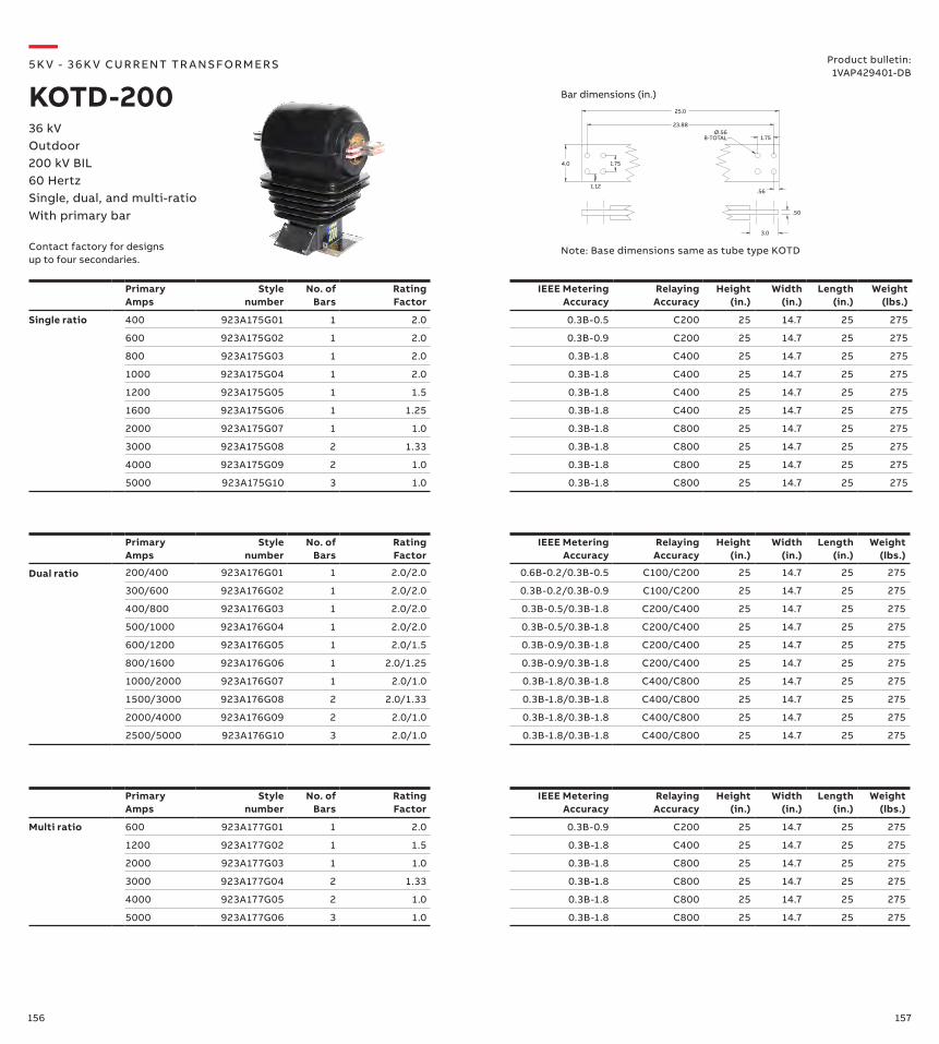
156 157
Primary Amps
Style number
No. of Bars
Rating Factor
IEEE Metering Accuracy
Relaying Accuracy
Height (in.)
Width (in.)
Length (in.)
Weight (lbs.)
Multi ratio 600 923A177G01 1 2.0 0.3B-0.9 C200 25 14.7 25 275
1200 923A177G02 1 1.5 0.3B-1.8 C400 25 14.7 25 275
2000 923A177G03 1 1.0 0.3B-1.8 C800 25 14.7 25 275
3000 923A177G04 2 1.33 0.3B-1.8 C800 25 14.7 25 275
4000 923A177G05 2 1.0 0.3B-1.8 C800 25 14.7 25 275
5000 923A177G06 3 1.0 0.3B-1.8 C800 25 14.7 25 275
Primary Amps
Style number
No. of Bars
Rating Factor
IEEE Metering Accuracy
Relaying Accuracy
Height (in.)
Width (in.)
Length (in.)
Weight (lbs.)
Dual ratio 200/400 923A176G01 1 2.0/2.0 0.6B-0.2/0.3B-0.5 C100/C200 25 14.7 25 275
300/600 923A176G02 1 2.0/2.0 0.3B-0.2/0.3B-0.9 C100/C200 25 14.7 25 275
400/800 923A176G03 1 2.0/2.0 0.3B-0.5/0.3B-1.8 C200/C400 25 14.7 25 275
500/1000 923A176G04 1 2.0/2.0 0.3B-0.5/0.3B-1.8 C200/C400 25 14.7 25 275
600/1200 923A176G05 1 2.0/1.5 0.3B-0.9/0.3B-1.8 C200/C400 25 14.7 25 275
800/1600 923A176G06 1 2.0/1.25 0.3B-0.9/0.3B-1.8 C200/C400 25 14.7 25 275
1000/2000 923A176G07 1 2.0/1.0 0.3B-1.8/0.3B-1.8 C400/C800 25 14.7 25 275
1500/3000 923A176G08 2 2.0/1.33 0.3B-1.8/0.3B-1.8 C400/C800 25 14.7 25 275
2000/4000 923A176G09 2 2.0/1.0 0.3B-1.8/0.3B-1.8 C400/C800 25 14.7 25 275
2500/5000 923A176G10 3 2.0/1.0 0.3B-1.8/0.3B-1.8 C400/C800 25 14.7 25 275
Primary Amps
Style number
No. of Bars
Rating Factor
IEEE Metering Accuracy
Relaying Accuracy
Height (in.)
Width (in.)
Length (in.)
Weight (lbs.)
Single ratio 400 923A175G01 1 2.0 0.3B-0.5 C200 25 14.7 25 275
600 923A175G02 1 2.0 0.3B-0.9 C200 25 14.7 25 275
800 923A175G03 1 2.0 0.3B-1.8 C400 25 14.7 25 275
1000 923A175G04 1 2.0 0.3B-1.8 C400 25 14.7 25 275
1200 923A175G05 1 1.5 0.3B-1.8 C400 25 14.7 25 275
1600 923A175G06 1 1.25 0.3B-1.8 C400 25 14.7 25 275
2000 923A175G07 1 1.0 0.3B-1.8 C800 25 14.7 25 275
3000 923A175G08 2 1.33 0.3B-1.8 C800 25 14.7 25 275
4000 923A175G09 2 1.0 0.3B-1.8 C800 25 14.7 25 275
5000 923A175G10 3 1.0 0.3B-1.8 C800 25 14.7 25 275
25.0
4.0
1.12
1.75
1.75
23.88
.56
Ø.56 8-TOTAL
.50
3.0
—5K V - 3 6 K V CU R R ENT TR A NS FO R M ER S
KOTD-20036 kVOutdoor200 kV BIL60 HertzSingle, dual, and multi-ratioWith primary bar
Note: Base dimensions same as tube type KOTD
Bar dimensions (in.)
Product bulletin:1VAP429401-DB
Contact factory for designs up to four secondaries.
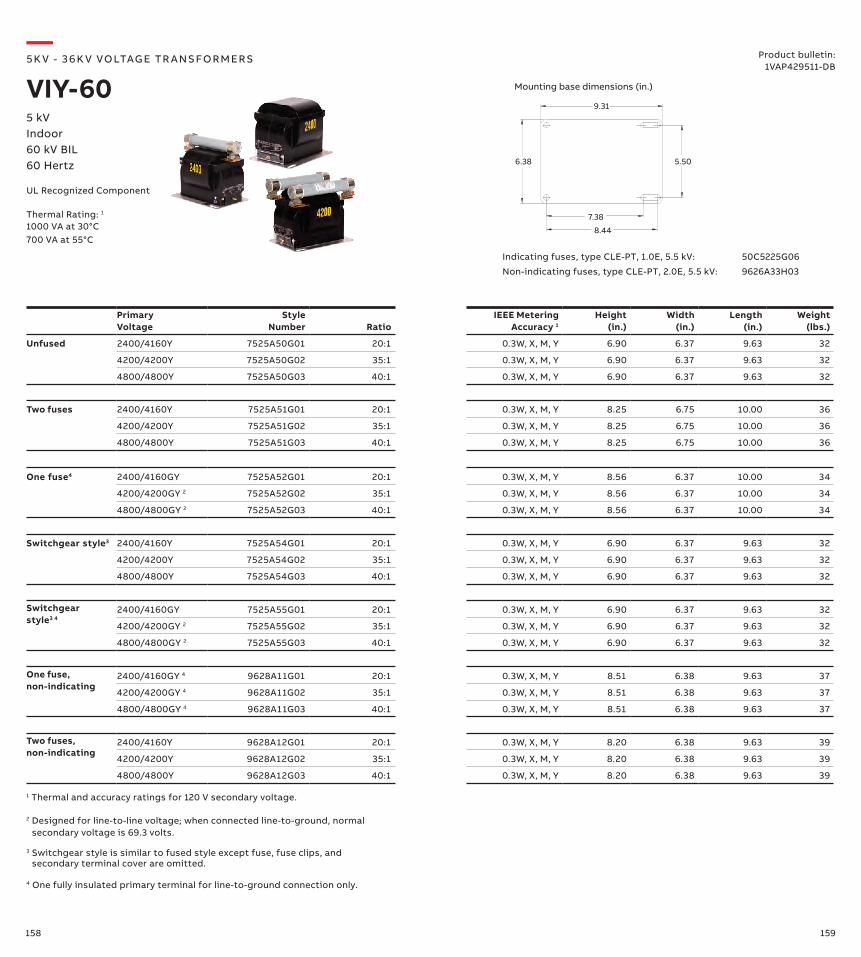
158 159
Primary Voltage
Style Number Ratio
IEEE Metering Accuracy 1
Height (in.)
Width (in.)
Length (in.)
Weight (lbs.)
Unfused 2400/4160Y 7525A50G01 20:1 0.3W, X, M, Y 6.90 6.37 9.63 32
4200/4200Y 7525A50G02 35:1 0.3W, X, M, Y 6.90 6.37 9.63 32
4800/4800Y 7525A50G03 40:1 0.3W, X, M, Y 6.90 6.37 9.63 32
9.31
5.50
7.38
8.44
6.38
Indicating fuses, type CLE-PT, 1.0E, 5.5 kV: 50C5225G06
Non-indicating fuses, type CLE-PT, 2.0E, 5.5 kV: 9626A33H03
Two fuses 2400/4160Y 7525A51G01 20:1 0.3W, X, M, Y 8.25 6.75 10.00 36
4200/4200Y 7525A51G02 35:1 0.3W, X, M, Y 8.25 6.75 10.00 36
4800/4800Y 7525A51G03 40:1 0.3W, X, M, Y 8.25 6.75 10.00 36
One fuse4 2400/4160GY 7525A52G01 20:1 0.3W, X, M, Y 8.56 6.37 10.00 34
4200/4200GY 2 7525A52G02 35:1 0.3W, X, M, Y 8.56 6.37 10.00 34
4800/4800GY 2 7525A52G03 40:1 0.3W, X, M, Y 8.56 6.37 10.00 34
Switchgear style3 2400/4160Y 7525A54G01 20:1 0.3W, X, M, Y 6.90 6.37 9.63 32
4200/4200Y 7525A54G02 35:1 0.3W, X, M, Y 6.90 6.37 9.63 32
4800/4800Y 7525A54G03 40:1 0.3W, X, M, Y 6.90 6.37 9.63 32
Switchgearstyle3 4
2400/4160GY 7525A55G01 20:1 0.3W, X, M, Y 6.90 6.37 9.63 32
4200/4200GY 2 7525A55G02 35:1 0.3W, X, M, Y 6.90 6.37 9.63 32
4800/4800GY 2 7525A55G03 40:1 0.3W, X, M, Y 6.90 6.37 9.63 32
One fuse,non-indicating
2400/4160GY 4 9628A11G01 20:1 0.3W, X, M, Y 8.51 6.38 9.63 37
4200/4200GY 4 9628A11G02 35:1 0.3W, X, M, Y 8.51 6.38 9.63 37
4800/4800GY 4 9628A11G03 40:1 0.3W, X, M, Y 8.51 6.38 9.63 37
Two fuses,non-indicating
2400/4160Y 9628A12G01 20:1 0.3W, X, M, Y 8.20 6.38 9.63 39
4200/4200Y 9628A12G02 35:1 0.3W, X, M, Y 8.20 6.38 9.63 39
4800/4800Y 9628A12G03 40:1 0.3W, X, M, Y 8.20 6.38 9.63 39
1 Thermal and accuracy ratings for 120 V secondary voltage.
2 Designed for line-to-line voltage; when connected line-to-ground, normal secondary voltage is 69.3 volts.
3 Switchgear style is similar to fused style except fuse, fuse clips, and secondary terminal cover are omitted.
4 One fully insulated primary terminal for line-to-ground connection only.
—5K V - 3 6 K V VO LTAG E TR A NS FO R M ER S
VIY-605 kVIndoor60 kV BIL60 Hertz
Product bulletin:1VAP429511-DB
UL Recognized Component
Thermal Rating: 1
1000 VA at 30°C700 VA at 55°C
Mounting base dimensions (in.)
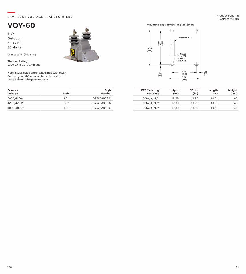
160 161
Primary Voltage Ratio
Style Number
IEEE Metering Accuracy
Height (in.)
Width (in.)
Length (in.)
Weight (lbs.)
2400/4160Y 20:1 E-7525A85G01 0.3W, X, M, Y 12.39 11.25 10.61 40
4200/4200Y 35:1 E-7525A85G02 0.3W, X, M, Y 12.39 11.25 10.61 40
4800/4800Y 40:1 E-7525A85G03 0.3W, X, M, Y 12.39 11.25 10.61 40
9.36[238]
8.49[216]
.44[11]
6.24[158]
7.61[193]
.68[17]
.44 x .88[11 x 22]SLOTS4-TOTAL
NAMEPLATE
—5K V - 3 6 K V VO LTAG E TR A NS FO R M ER S
VOY-605 kVOutdoor60 kV BIL60 Hertz
Product bulletin:1VAP429611-DB
Mounting base dimensions (in.) [mm]
Note: Styles listed are encapsulated with HCEP. Contact your ABB representative for styles encapsulated with polyurethane.
Creep: 15.8" (401 mm)
Thermal Rating:1000 VA @ 30°C ambient
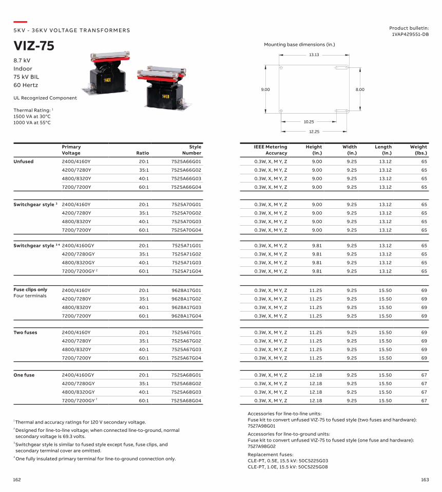
162 163
Two fuses 2400/4160Y 20:1 7525A67G01 0.3W, X, M Y, Z 11.25 9.25 15.50 69
4200/7280Y 35:1 7525A67G02 0.3W, X, M Y, Z 11.25 9.25 15.50 69
4800/8320Y 40:1 7525A67G03 0.3W, X, M Y, Z 11.25 9.25 15.50 69
7200/7200Y 60:1 7525A67G04 0.3W, X, M Y, Z 11.25 9.25 15.50 69
Primary Voltage Ratio
Style Number
IEEE Metering Accuracy
Height (in.)
Width (in.)
Length (in.)
Weight (lbs.)
Unfused 2400/4160Y 20:1 7525A66G01 0.3W, X, M Y, Z 9.00 9.25 13.12 65
4200/7280Y 35:1 7525A66G02 0.3W, X, M Y, Z 9.00 9.25 13.12 65
4800/8320Y 40:1 7525A66G03 0.3W, X, M Y, Z 9.00 9.25 13.12 65
7200/7200Y 60:1 7525A66G04 0.3W, X, M Y, Z 9.00 9.25 13.12 65
13.13
8.00
12.25
10.25
9.00
One fuse 2400/4160GY 20:1 7525A68G01 0.3W, X, M Y, Z 12.18 9.25 15.50 67
4200/7280GY 35:1 7525A68G02 0.3W, X, M Y, Z 12.18 9.25 15.50 67
4800/8320GY 40:1 7525A68G03 0.3W, X, M Y, Z 12.18 9.25 15.50 67
7200/7200GY 2 60:1 7525A68G04 0.3W, X, M Y, Z 12.18 9.25 15.50 67
Accessories for line-to-line units:Fuse kit to convert unfused VIZ-75 to fused style (two fuses and hardware): 7527A98G01
Accessories for line-to-ground units:Fuse kit to convert unfused VIZ-75 to fused style (one fuse and hardware): 7527A98G02
Switchgear style 3 2400/4160Y 20:1 7525A70G01 0.3W, X, M Y, Z 9.00 9.25 13.12 65
4200/7280Y 35:1 7525A70G02 0.3W, X, M Y, Z 9.00 9.25 13.12 65
4800/8320Y 40:1 7525A70G03 0.3W, X, M Y, Z 9.00 9.25 13.12 65
7200/7200Y 60:1 7525A70G04 0.3W, X, M Y, Z 9.00 9.25 13.12 65
Switchgear style 3 4 2400/4160GY 20:1 7525A71G01 0.3W, X, M Y, Z 9.81 9.25 13.12 65
4200/7280GY 35:1 7525A71G02 0.3W, X, M Y, Z 9.81 9.25 13.12 65
4800/8320GY 40:1 7525A71G03 0.3W, X, M Y, Z 9.81 9.25 13.12 65
7200/7200GY 2 60:1 7525A71G04 0.3W, X, M Y, Z 9.81 9.25 13.12 65
Fuse clips onlyFour terminals
2400/4160Y 20:1 9628A17G01 0.3W, X, M Y, Z 11.25 9.25 15.50 69
4200/7280Y 35:1 9628A17G02 0.3W, X, M Y, Z 11.25 9.25 15.50 69
4800/8320Y 40:1 9628A17G03 0.3W, X, M Y, Z 11.25 9.25 15.50 69
7200/7200Y 60:1 9628A17G04 0.3W, X, M Y, Z 11.25 9.25 15.50 69
Replacement fuses:CLE-PT, 0.5E, 15.5 kV: 50C5225G03CLE-PT, 1.0E, 15.5 kV: 50C5225G08
—5K V - 3 6 K V VO LTAG E TR A NS FO R M ER S
VIZ-758.7 kVIndoor75 kV BIL60 Hertz
Product bulletin:1VAP429551-DB
UL Recognized Component
Mounting base dimensions (in.)
1 Thermal and accuracy ratings for 120 V secondary voltage.2 Designed for line-to-line voltage; when connected line-to-ground, normal secondary voltage is 69.3 volts.
3 Switchgear style is similar to fused style except fuse, fuse clips, and secondary terminal cover are omitted.
4 One fully insulated primary terminal for line-to-ground connection only.
Thermal Rating: 1
1500 VA at 30°C1000 VA at 55°C
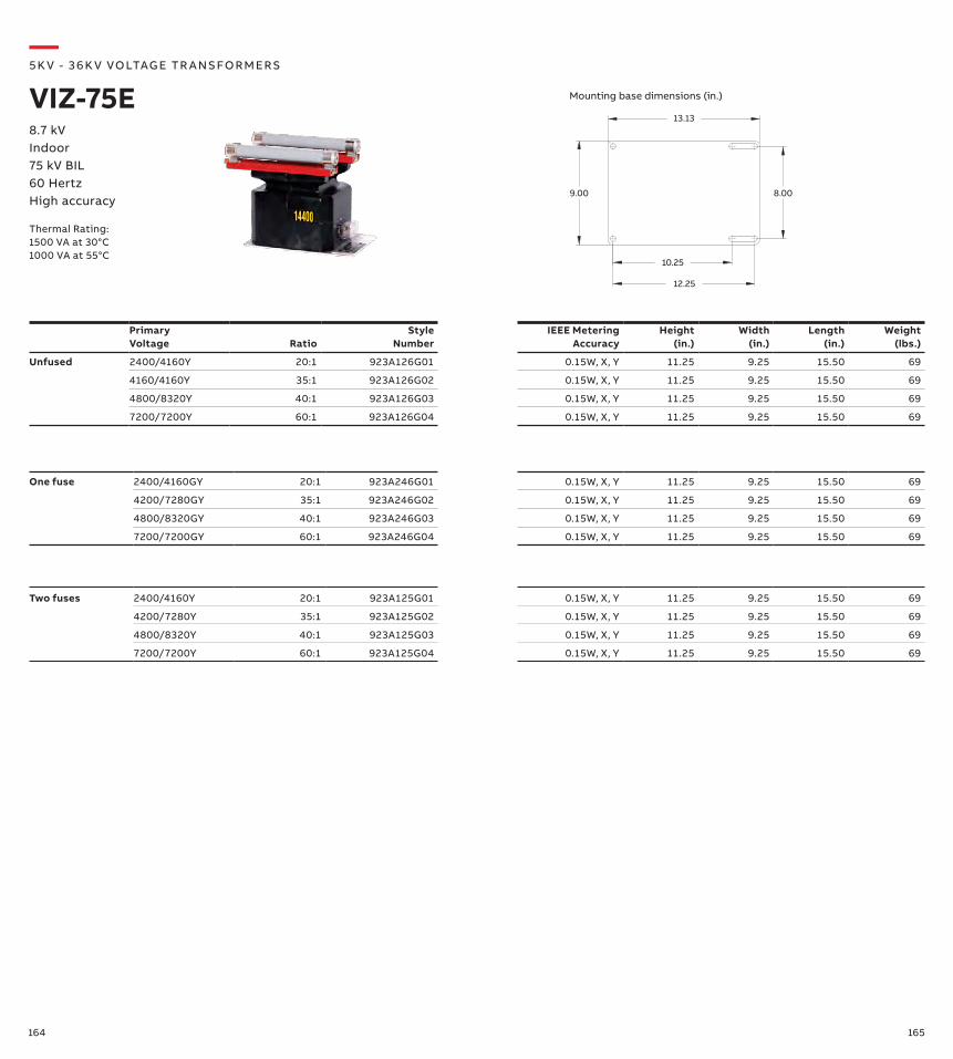
164 165
Primary Voltage Ratio
Style Number
IEEE Metering Accuracy
Height (in.)
Width (in.)
Length (in.)
Weight (lbs.)
Unfused 2400/4160Y 20:1 923A126G01 0.15W, X, Y 11.25 9.25 15.50 69
4160/4160Y 35:1 923A126G02 0.15W, X, Y 11.25 9.25 15.50 69
4800/8320Y 40:1 923A126G03 0.15W, X, Y 11.25 9.25 15.50 69
7200/7200Y 60:1 923A126G04 0.15W, X, Y 11.25 9.25 15.50 69
—5K V - 3 6 K V VO LTAG E TR A NS FO R M ER S
VIZ-75E8.7 kVIndoor75 kV BIL60 HertzHigh accuracy
13.13
8.00
12.25
10.25
9.00
Thermal Rating:1500 VA at 30°C1000 VA at 55°C
Mounting base dimensions (in.)
Two fuses 2400/4160Y 20:1 923A125G01 0.15W, X, Y 11.25 9.25 15.50 69
4200/7280Y 35:1 923A125G02 0.15W, X, Y 11.25 9.25 15.50 69
4800/8320Y 40:1 923A125G03 0.15W, X, Y 11.25 9.25 15.50 69
7200/7200Y 60:1 923A125G04 0.15W, X, Y 11.25 9.25 15.50 69
One fuse 2400/4160GY 20:1 923A246G01 0.15W, X, Y 11.25 9.25 15.50 69
4200/7280GY 35:1 923A246G02 0.15W, X, Y 11.25 9.25 15.50 69
4800/8320GY 40:1 923A246G03 0.15W, X, Y 11.25 9.25 15.50 69
7200/7200GY 60:1 923A246G04 0.15W, X, Y 11.25 9.25 15.50 69
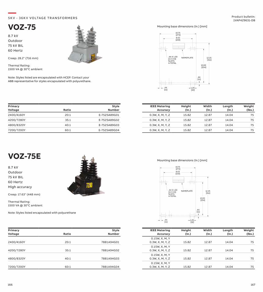
166 167
Primary Voltage Ratio
Style Number
IEEE Metering Accuracy
Height (in.)
Width (in.)
Length (in.)
Weight (lbs.)
2400/4160Y 20:1 7881A94G010.15W, X, M, Y
0.3W, X, M, Y, Z 15.82 12.87 14.04 75
4200/7280Y 35:1 7881A94G020.15W, X, M, Y
0.3W, X, M, Y, Z 15.82 12.87 14.04 75
4800/8320Y 40:1 7881A94G030.15W, X, M, Y
0.3W, X, M, Y, Z 15.82 12.87 14.04 75
7200/7200Y 60:1 7881A94G040.15W, X, M, Y
0.3W, X, M, Y, Z 15.82 12.87 14.04 75
12.25 [311]
.44 [11]
10.00 [254]
.44 [11]
8.63[219]
10.75 [273]
1.25 [32]
.44 X 1.69[11 X 43]SLOTS4-TOTAL
NAMEPLATE
Primary Voltage Ratio
Style Number
IEEE Metering Accuracy
Height (in.)
Width (in.)
Length (in.)
Weight (lbs.)
2400/4160Y 20:1 E-7525A89G01 0.3W, X, M, Y, Z 15.82 12.87 14.04 75
4200/7280Y 35:1 E-7525A89G02 0.3W, X, M, Y, Z 15.82 12.87 14.04 75
4800/8320Y 40:1 E-7525A89G03 0.3W, X, M, Y, Z 15.82 12.87 14.04 75
7200/7200Y 60:1 E-7525A89G04 0.3W, X, M, Y, Z 15.82 12.87 14.04 75
12.25 [311]
.44 [11]
10.00 [254]
.44 [11]
8.63[219]
10.75 [273]
1.25 [32]
.44 X 1.69[11 X 43]SLOTS4-TOTAL
NAMEPLATE
VOZ-75E
—5K V - 3 6 K V VO LTAG E TR A NS FO R M ER S
VOZ-758.7 kVOutdoor75 kV BIL60 Hertz
Product bulletin:1VAP429631-DB
8.7 kVOutdoor75 kV BIL60 HertzHigh accuracy
Creep: 28.2" (716 mm)
Thermal Rating:1500 VA @ 30°C ambient
Creep: 17.63" (448 mm)
Thermal Rating:1500 VA @ 30°C ambient
Note: Styles listed encapsulated with polyurethane
Mounting base dimensions (in.) [mm]
Mounting base dimensions (in.) [mm]
Note: Styles listed are encapsulated with HCEP. Contact your ABB representative for styles encapsulated with polyurethane.

168 169
Primary Voltage Ratio
Style Number
IEEE Metering Accuracy
Height (in.)
Width (in.)
Length (in.)
Weight (lbs.)
VIL-95S(cable leads)
2400/4160Y 20:1 7883A12G01 0.3W, X, M, Y 13.94 12.38 12.0 105
4200/7280Y 35:1 7883A12G02 0.3W, X, M, Y 13.94 12.38 12.0 105
4800/8320Y 40:1 7883A12G03 0.3W, X, M, Y 13.94 12.38 12.0 105
7200/12470Y 60:1 7883A12G04 0.3W, X, M, Y 13.94 12.38 12.0 105
7620/13200Y 63.5:1 7883A12G05 0.3W, X, M, Y 13.94 12.38 12.0 105
8400/14560Y 70:1 7883A12G06 0.3W, X, M, Y 13.94 12.38 12.0 105
12000/12000Y 100:1 7883A12G07 0.3W, X, M, Y 13.94 12.38 12.0 105
7970/13800Y 66.42:1 7883A12G08 0.3W, X, M, Y 13.94 12.38 12.0 105
6928/12000Y 57.73:1 7883A12G09 0.3W, X, M, Y 13.94 12.38 12.0 105
Primary Voltage Ratio
Style Number
IEEE Metering Accuracy
Height (in.)
Width (in.)
Length (in.)
Weight (lbs.)
VIL-95(junction box)
2400/4160Y 20:1 7881A93G01 0.3W, X, M, Y, Z 13.94 15.55 12.0 105
4200/7280Y 35:1 7881A93G02 0.3W, X, M, Y, Z 13.94 15.55 12.0 105
4800/8320Y 40:1 7881A93G03 0.3W, X, M, Y, Z 13.94 15.55 12.0 105
7200/12470Y 60:1 7881A93G04 0.3W, X, M, Y, Z 13.94 15.55 12.0 105
7620/13200Y 63.5:1 7881A93G05 0.3W, X, M, Y, Z 13.94 15.55 12.0 105
8400/14560Y 70:1 7881A93G06 0.3W, X, M, Y, Z 13.94 15.55 12.0 105
12000/12000Y 100:1 7881A93G07 0.3W, X, M, Y, Z 13.94 15.55 12.0 105
13200/13200Y 110:1 7881A93G08 0.3W, X, M, Y, Z 13.94 15.55 12.0 105
14400/14400Y 120:1 7881A93G09 0.3W, X, M, Y, Z 13.94 15.55 12.0 105
.438 x 1.188 SLOT2-TOTAL
12.38 10.75
.44
11.1312.00
Ø.442-TOTAL
.44
—5K V - 3 6 K V VO LTAG E TR A NS FO R M ER S
VIL-95 and VIL-95S15 kVIndoor95 kV BIL60 Hertz
UL Recognized Component
Thermal Rating:VIL-95: 1500 VA at 30°C1000 VA at 55°C
VIL-95S:750 VA at 30°C500 VA at 55°C
Product bulletin:1VAP429581-DB
Mounting base dimensions (in.)
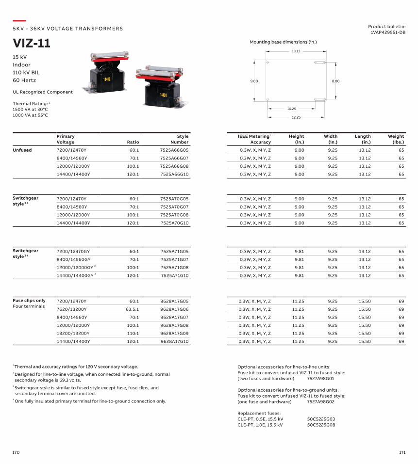
170 171
Fuse clips onlyFour terminals
7200/12470Y 60:1 9628A17G05 0.3W, X, M, Y, Z 11.25 9.25 15.50 69
7620/13200Y 63.5:1 9628A17G06 0.3W, X, M, Y, Z 11.25 9.25 15.50 69
8400/14560Y 70:1 9628A17G07 0.3W, X, M, Y, Z 11.25 9.25 15.50 69
12000/12000Y 100:1 9628A17G08 0.3W, X, M, Y, Z 11.25 9.25 15.50 69
13200/13200Y 110:1 9628A17G09 0.3W, X, M, Y, Z 11.25 9.25 15.50 69
14400/14400Y 120:1 9628A17G10 0.3W, X, M, Y, Z 11.25 9.25 15.50 69
Switchgearstyle 3 4
7200/12470GY 60:1 7525A71G05 0.3W, X, M Y, Z 9.81 9.25 13.12 65
8400/14560GY 70:1 7525A71G07 0.3W, X, M Y, Z 9.81 9.25 13.12 65
12000/12000GY 2 100:1 7525A71G08 0.3W, X, M Y, Z 9.81 9.25 13.12 65
14400/14400GY 2 120:1 7525A71G10 0.3W, X, M Y, Z 9.81 9.25 13.12 65
Switchgearstyle 3 4
7200/12470Y 60:1 7525A70G05 0.3W, X, M Y, Z 9.00 9.25 13.12 65
8400/14560Y 70:1 7525A70G07 0.3W, X, M Y, Z 9.00 9.25 13.12 65
12000/12000Y 100:1 7525A70G08 0.3W, X, M Y, Z 9.00 9.25 13.12 65
14400/14400Y 120:1 7525A70G10 0.3W, X, M Y, Z 9.00 9.25 13.12 65
Primary Voltage Ratio
Style Number
IEEE Metering1 Accuracy
Height (in.)
Width (in.)
Length (in.)
Weight (lbs.)
Unfused 7200/12470Y 60:1 7525A66G05 0.3W, X, M Y, Z 9.00 9.25 13.12 65
8400/14560Y 70:1 7525A66G07 0.3W, X, M Y, Z 9.00 9.25 13.12 65
12000/12000Y 100:1 7525A66G08 0.3W, X, M Y, Z 9.00 9.25 13.12 65
14400/14400Y 120:1 7525A66G10 0.3W, X, M Y, Z 9.00 9.25 13.12 65
13.13
8.00
12.25
10.25
9.00
Optional accessories for line-to-line units:Fuse kit to convert unfused VIZ-11 to fused style: (two fuses and hardware) 7527A98G01
Optional accessories for line-to-ground units:Fuse kit to convert unfused VIZ-11 to fused style: (one fuse and hardware) 7527A98G02
Replacement fuses:CLE-PT, 0.5E, 15.5 kV 50C5225G03CLE-PT, 1.0E, 15.5 kV 50C5225G08
—5K V - 3 6 K V VO LTAG E TR A NS FO R M ER S
VIZ-1115 kVIndoor110 kV BIL60 Hertz
Product bulletin:1VAP429551-DB
UL Recognized Component
Thermal Rating: 1
1500 VA at 30°C1000 VA at 55°C
Mounting base dimensions (in.)
1 Thermal and accuracy ratings for 120 V secondary voltage.2 Designed for line-to-line voltage; when connected line-to-ground, normal secondary voltage is 69.3 volts.
3 Switchgear style is similar to fused style except fuse, fuse clips, and secondary terminal cover are omitted.
4 One fully insulated primary terminal for line-to-ground connection only.
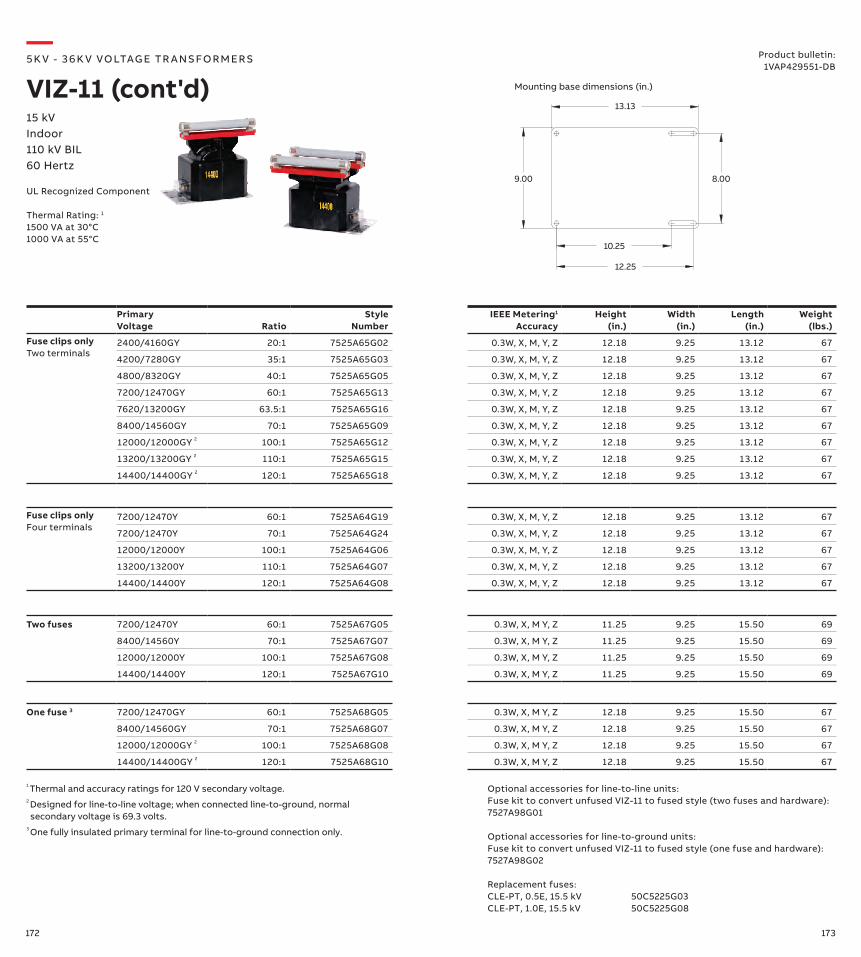
172 173
Two fuses 7200/12470Y 60:1 7525A67G05 0.3W, X, M Y, Z 11.25 9.25 15.50 69
8400/14560Y 70:1 7525A67G07 0.3W, X, M Y, Z 11.25 9.25 15.50 69
12000/12000Y 100:1 7525A67G08 0.3W, X, M Y, Z 11.25 9.25 15.50 69
14400/14400Y 120:1 7525A67G10 0.3W, X, M Y, Z 11.25 9.25 15.50 69
Optional accessories for line-to-line units:Fuse kit to convert unfused VIZ-11 to fused style (two fuses and hardware): 7527A98G01
Optional accessories for line-to-ground units:Fuse kit to convert unfused VIZ-11 to fused style (one fuse and hardware): 7527A98G02
Replacement fuses:CLE-PT, 0.5E, 15.5 kV 50C5225G03CLE-PT, 1.0E, 15.5 kV 50C5225G08
Primary Voltage Ratio
Style Number
IEEE Metering1 Accuracy
Height (in.)
Width (in.)
Length (in.)
Weight (lbs.)
Fuse clips onlyTwo terminals
2400/4160GY 20:1 7525A65G02 0.3W, X, M, Y, Z 12.18 9.25 13.12 67
4200/7280GY 35:1 7525A65G03 0.3W, X, M, Y, Z 12.18 9.25 13.12 67
4800/8320GY 40:1 7525A65G05 0.3W, X, M, Y, Z 12.18 9.25 13.12 67
7200/12470GY 60:1 7525A65G13 0.3W, X, M, Y, Z 12.18 9.25 13.12 67
7620/13200GY 63.5:1 7525A65G16 0.3W, X, M, Y, Z 12.18 9.25 13.12 67
8400/14560GY 70:1 7525A65G09 0.3W, X, M, Y, Z 12.18 9.25 13.12 67
12000/12000GY 2 100:1 7525A65G12 0.3W, X, M, Y, Z 12.18 9.25 13.12 67
13200/13200GY 2 110:1 7525A65G15 0.3W, X, M, Y, Z 12.18 9.25 13.12 67
14400/14400GY 2 120:1 7525A65G18 0.3W, X, M, Y, Z 12.18 9.25 13.12 67
One fuse 3 7200/12470GY 60:1 7525A68G05 0.3W, X, M Y, Z 12.18 9.25 15.50 67
8400/14560GY 70:1 7525A68G07 0.3W, X, M Y, Z 12.18 9.25 15.50 67
12000/12000GY 2 100:1 7525A68G08 0.3W, X, M Y, Z 12.18 9.25 15.50 67
14400/14400GY 2 120:1 7525A68G10 0.3W, X, M Y, Z 12.18 9.25 15.50 67
Fuse clips onlyFour terminals
7200/12470Y 60:1 7525A64G19 0.3W, X, M, Y, Z 12.18 9.25 13.12 67
7200/12470Y 70:1 7525A64G24 0.3W, X, M, Y, Z 12.18 9.25 13.12 67
12000/12000Y 100:1 7525A64G06 0.3W, X, M, Y, Z 12.18 9.25 13.12 67
13200/13200Y 110:1 7525A64G07 0.3W, X, M, Y, Z 12.18 9.25 13.12 67
14400/14400Y 120:1 7525A64G08 0.3W, X, M, Y, Z 12.18 9.25 13.12 67
—5K V - 3 6 K V VO LTAG E TR A NS FO R M ER S
VIZ-11 (cont'd)Product bulletin:
1VAP429551-DB
13.13
8.00
12.25
10.25
9.00
15 kVIndoor110 kV BIL60 Hertz
UL Recognized Component
Thermal Rating: 1
1500 VA at 30°C1000 VA at 55°C
Mounting base dimensions (in.)
1 Thermal and accuracy ratings for 120 V secondary voltage.2 Designed for line-to-line voltage; when connected line-to-ground, normal secondary voltage is 69.3 volts.
3 One fully insulated primary terminal for line-to-ground connection only.
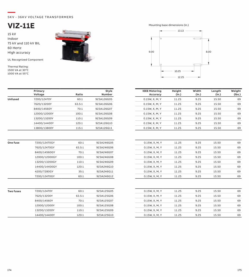
174 175
Primary Voltage Ratio
Style Number
IEEE Metering Accuracy
Height (in.)
Width (in.)
Length (in.)
Weight (lbs.)
Unfused 7200/12470Y 60:1 923A126G05 0.15W, X, M, Y 11.25 9.25 15.50 69
7620/13200Y 63.5:1 923A126G06 0.15W, X, M, Y 11.25 9.25 15.50 69
8400/14560Y 70:1 923A126G07 0.15W, X, M, Y 11.25 9.25 15.50 69
12000/12000Y 100:1 923A126G08 0.15W, X, M, Y 11.25 9.25 15.50 69
13200/13200Y 110:1 923A126G09 0.15W, X, M, Y 11.25 9.25 15.50 69
14400/14400Y 120:1 923A126G10 0.15W, X, M, Y 11.25 9.25 15.50 69
13800/13800Y 115:1 923A126G11 0.15W, X, M, Y 11.25 9.25 15.50 69
—5K V - 3 6 K V VO LTAG E TR A NS FO R M ER S
VIZ-11E15 kVIndoor75 kV and 110 kV BIL60 HertzHigh accuracy
13.13
8.00
12.25
10.25
9.00
UL Recognized Component
Thermal Rating:1500 VA at 30°C1000 VA at 55°C
Mounting base dimensions (in.)
Two fuses 7200/12470Y 60:1 923A125G05 0.15W, X, M, Y 11.25 9.25 15.50 69
7620/13200Y 63.5:1 923A125G06 0.15W, X, M, Y 11.25 9.25 15.50 69
8400/14560Y 70:1 923A125G07 0.15W, X, M, Y 11.25 9.25 15.50 69
12000/12000Y 100:1 923A125G08 0.15W, X, M, Y 11.25 9.25 15.50 69
13200/13200Y 110:1 923A125G09 0.15W, X, M, Y 11.25 9.25 15.50 69
14400/14400Y 120:1 923A125G10 0.15W, X, M, Y 11.25 9.25 15.50 69
One fuse 7200/12470GY 60:1 923A246G05 0.15W, X, M, Y 11.25 9.25 15.50 69
7620/12470GY 63.5:1 923A246G06 0.15W, X, M, Y 11.25 9.25 15.50 69
8400/14560GY 70:1 923A246G07 0.15W, X, M, Y 11.25 9.25 15.50 69
12000/12000GY 100:1 923A246G08 0.15W, X, M, Y 11.25 9.25 15.50 69
13200/13200GY 110:1 923A246G09 0.15W, X, M, Y 11.25 9.25 15.50 69
14400/14400GY 120:1 923A246G10 0.15W, X, M, Y 11.25 9.25 15.50 69
4200/7280GY 35:1 923A246G11 0.15W, X, M, Y 11.25 9.25 15.50 69
7200/12470GY 60:1 923A246G12 0.15W, X, M, Y 11.25 9.25 15.50 69
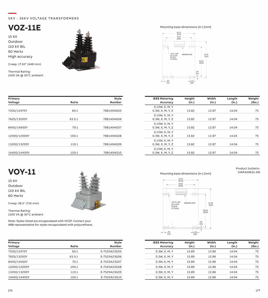
176 177
Primary Voltage Ratio
Style Number
IEEE Metering Accuracy
Height (in.)
Width (in.)
Length (in.)
Weight (lbs.)
7200/12470Y 60:1 7881A94G050.15W, X, M, Y
0.3W, X, M, Y, Z 15.82 12.87 14.04 75
7620/13200Y 63.5:1 7881A94G060.15W, X, M, Y
0.3W, X, M, Y, Z 15.82 12.87 14.04 75
8400/14560Y 70:1 7881A94G070.15W, X, M, Y
0.3W, X, M, Y, Z 15.82 12.87 14.04 75
12000/12000Y 100:1 7881A94G080.15W, X, M, Y
0.3W, X, M, Y, Z 15.82 12.87 14.04 75
13200/13200Y 110:1 7881A94G090.15W, X, M, Y
0.3W, X, M, Y, Z 15.82 12.87 14.04 75
14400/14400Y 120:1 7881A94G100.15W, X, M, Y
0.3W, X, M, Y, Z 15.82 12.87 14.04 75
12.25 [311]
.44 [11]
10.00 [254]
.44 [11]
8.63[219]
10.75 [273]
1.25 [32]
.44 X 1.69[11 X 43]SLOTS4-TOTAL
NAMEPLATE
Primary Voltage Ratio
Style Number
IEEE Metering Accuracy
Height (in.)
Width (in.)
Length (in.)
Weight (lbs.)
7200/12470Y 60:1 E-7525A23G05 0.3W, X, M, Y 15.89 12.86 14.04 75
7620/13200Y 63.5:1 E-7525A23G06 0.3W, X, M, Y 15.89 12.86 14.04 75
8400/14560Y 70:1 E-7525A23G07 0.3W, X, M, Y 15.89 12.86 14.04 75
12000/12000Y 100:1 E-7525A23G08 0.3W, X, M, Y 15.89 12.86 14.04 75
13200/13200Y 110:1 E-7525A23G09 0.3W, X, M, Y 15.89 12.86 14.04 75
14400/14400Y 120:1 E-7525A23G10 0.3W, X, M, Y 15.89 12.86 14.04 75
12.25 [311]
.44 [11]
10.00 [254]
.44 [11]
8.63[219]
10.75 [273]
1.25 [32]
.44 X 1.69[11 X 43]SLOTS4-TOTAL
NAMEPLATE
—5K V - 3 6 K V VO LTAG E TR A NS FO R M ER S
VOZ-11E15 kVOutdoor110 kV BIL60 HertzHigh accuracy
VOY-11 Product bulletin:1VAP429631-DB
15 kVOutdoor110 kV BIL60 Hertz
Mounting base dimensions (in.) [mm]
Mounting base dimensions (in.) [mm]
Note: Styles listed are encapsulated with HCEP. Contact your ABB representative for styles encapsulated with polyurethane.
Creep: 17.63" (448 mm)
Thermal Rating:1500 VA @ 30°C ambient
Creep: 28.2" (716 mm)
Thermal Rating:1500 VA @ 30°C ambient
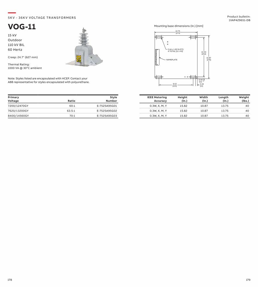
178 179
0.44 x 1.69 SLOTS4 TOTAL [11 x 43]
10.75 [273]
10.87 [276]
10.00 [254]
0.44 [11]
0.44 [11]
8.63 [219]
NAMEPLATE
Primary Voltage Ratio
Style Number
IEEE Metering Accuracy
Height (in.)
Width (in.)
Length (in.)
Weight (lbs.)
7200/12470GY 60:1 E-7525A95G01 0.3W, X, M, Y 15.82 10.87 13.75 40
7620/13200GY 63.5:1 E-7525A95G02 0.3W, X, M, Y 15.82 10.87 13.75 40
8400/14560GY 70:1 E-7525A95G03 0.3W, X, M, Y 15.82 10.87 13.75 40
—5K V - 3 6 K V VO LTAG E TR A NS FO R M ER S
VOG-1115 kVOutdoor110 kV BIL60 Hertz
Product bulletin:1VAP429651-DB
Creep: 24.7" (627 mm)
Thermal Rating:1000 VA @ 30°C ambient
Mounting base dimensions (in.) [mm]
Note: Styles listed are encapsulated with HCEP. Contact your ABB representative for styles encapsulated with polyurethane.
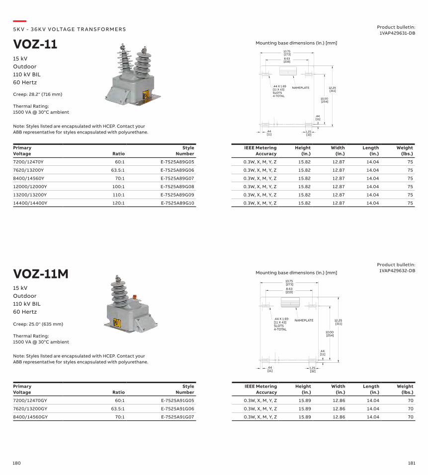
180 181
12.25 [311]
.44 [11]
10.00 [254]
.44 [11]
8.63[219]
10.75 [273]
1.25 [32]
.44 X 1.69[11 X 43]SLOTS4-TOTAL
NAMEPLATE
12.25 [311]
.44 [11]
10.00 [254]
.44 [11]
8.63[219]
10.75 [273]
1.25 [32]
.44 X 1.69[11 X 43]SLOTS4-TOTAL
NAMEPLATE
Primary Voltage Ratio
Style Number
IEEE Metering Accuracy
Height (in.)
Width (in.)
Length (in.)
Weight (lbs.)
7200/12470Y 60:1 E-7525A89G05 0.3W, X, M, Y, Z 15.82 12.87 14.04 75
7620/13200Y 63.5:1 E-7525A89G06 0.3W, X, M, Y, Z 15.82 12.87 14.04 75
8400/14560Y 70:1 E-7525A89G07 0.3W, X, M, Y, Z 15.82 12.87 14.04 75
12000/12000Y 100:1 E-7525A89G08 0.3W, X, M, Y, Z 15.82 12.87 14.04 75
13200/13200Y 110:1 E-7525A89G09 0.3W, X, M, Y, Z 15.82 12.87 14.04 75
14400/14400Y 120:1 E-7525A89G10 0.3W, X, M, Y, Z 15.82 12.87 14.04 75
Primary Voltage Ratio
Style Number
IEEE Metering Accuracy
Height (in.)
Width (in.)
Length (in.)
Weight (lbs.)
7200/12470GY 60:1 E-7525A91G05 0.3W, X, M, Y, Z 15.89 12.86 14.04 70
7620/13200GY 63.5:1 E-7525A91G06 0.3W, X, M, Y, Z 15.89 12.86 14.04 70
8400/14560GY 70:1 E-7525A91G07 0.3W, X, M, Y, Z 15.89 12.86 14.04 70
—5K V - 3 6 K V VO LTAG E TR A NS FO R M ER S
VOZ-1115 kVOutdoor110 kV BIL60 Hertz
Product bulletin:1VAP429631-DB
VOZ-11M15 kVOutdoor110 kV BIL60 Hertz
Product bulletin:1VAP429632-DB
Creep: 28.2" (716 mm)
Thermal Rating:1500 VA @ 30°C ambient
Creep: 25.0" (635 mm)
Thermal Rating:1500 VA @ 30°C ambient
Mounting base dimensions (in.) [mm]
Mounting base dimensions (in.) [mm]
Note: Styles listed are encapsulated with HCEP. Contact your ABB representative for styles encapsulated with polyurethane.
Note: Styles listed are encapsulated with HCEP. Contact your ABB representative for styles encapsulated with polyurethane.

182 183
—5K V - 3 6 K V VO LTAG E TR A NS FO R M ER S
VOY-12Product bulletin:
1VAP429661-DB
15 kVOutdoor110 kV BIL60 Hertz
Note: Styles listed are encapsulated with HCEP. Contact your ABB representative for styles encapsulated with polyurethane.
Creep: 28.2" (716 mm)
Thermal Rating:1000 VA @ 30°C ambient
Primary Voltage Ratio
Style Number
IEEE Metering Accuracy
Height (in.)
Width (in.)
Length (in.)
Weight (lbs.)
12000/20780Y 100:1 E-7525A87G01 0.3W, X, M, Y 15.82 12.87 14.04 75
14400/24940Y 120:1 E-7525A87G02 0.3W, X, M, Y 15.82 12.87 14.04 75
18000/18000Y 150:1 E-7525A87G03 0.3W, X, M, Y 15.82 12.87 14.04 75
24000/24000Y 200:1 E-7525A87G04 0.3W, X, M, Y 15.82 12.87 14.04 75
12.25 [311]
.44 [11]
10.00 [254]
.44 [11]
8.63[219]
10.75[273]
1.25 [32]
.44 X 1.69[11 X 43]SLOTS4-TOTAL
NAMEPLATE
Mounting base dimensions (in.) [mm]
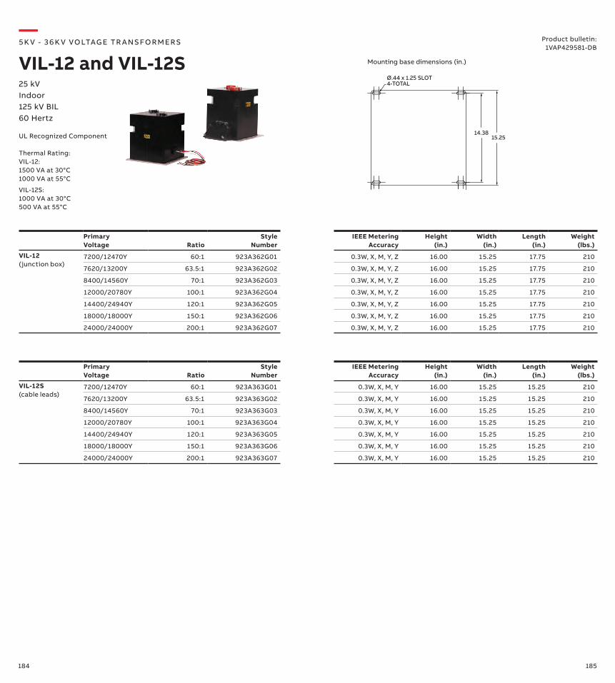
184 185
Primary Voltage Ratio
Style Number
IEEE Metering Accuracy
Height (in.)
Width (in.)
Length (in.)
Weight (lbs.)
VIL-12S(cable leads)
7200/12470Y 60:1 923A363G01 0.3W, X, M, Y 16.00 15.25 15.25 210
7620/13200Y 63.5:1 923A363G02 0.3W, X, M, Y 16.00 15.25 15.25 210
8400/14560Y 70:1 923A363G03 0.3W, X, M, Y 16.00 15.25 15.25 210
12000/20780Y 100:1 923A363G04 0.3W, X, M, Y 16.00 15.25 15.25 210
14400/24940Y 120:1 923A363G05 0.3W, X, M, Y 16.00 15.25 15.25 210
18000/18000Y 150:1 923A363G06 0.3W, X, M, Y 16.00 15.25 15.25 210
24000/24000Y 200:1 923A363G07 0.3W, X, M, Y 16.00 15.25 15.25 210
Primary Voltage Ratio
Style Number
IEEE Metering Accuracy
Height (in.)
Width (in.)
Length (in.)
Weight (lbs.)
VIL-12(junction box)
7200/12470Y 60:1 923A362G01 0.3W, X, M, Y, Z 16.00 15.25 17.75 210
7620/13200Y 63.5:1 923A362G02 0.3W, X, M, Y, Z 16.00 15.25 17.75 210
8400/14560Y 70:1 923A362G03 0.3W, X, M, Y, Z 16.00 15.25 17.75 210
12000/20780Y 100:1 923A362G04 0.3W, X, M, Y, Z 16.00 15.25 17.75 210
14400/24940Y 120:1 923A362G05 0.3W, X, M, Y, Z 16.00 15.25 17.75 210
18000/18000Y 150:1 923A362G06 0.3W, X, M, Y, Z 16.00 15.25 17.75 210
24000/24000Y 200:1 923A362G07 0.3W, X, M, Y, Z 16.00 15.25 17.75 210
Ø.44 x 1.25 SLOT4-TOTAL
15.25
15.2514.38
12.75
—5K V - 3 6 K V VO LTAG E TR A NS FO R M ER S
VIL-12 and VIL-12S25 kVIndoor125 kV BIL60 Hertz
Product bulletin:1VAP429581-DB
UL Recognized Component
Thermal Rating:VIL-12: 1500 VA at 30°C1000 VA at 55°C
VIL-12S:1000 VA at 30°C500 VA at 55°C
Mounting base dimensions (in.)
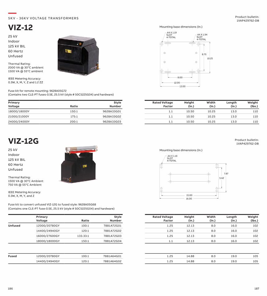
186 187
Primary Voltage Ratio
Style Number
Rated Voltage Factor
Height (in.)
Width (in.)
Length (in.)
Weight (lbs.)
18000/18000Y 150:1 9628A33G01 1.1 10.50 10.25 13.0 110
21000/21000Y 175:1 9628A33G02 1.1 10.50 10.25 13.0 110
24000/24000Y 200:1 9628A33G03 1.1 10.50 10.25 13.0 110
Primary Voltage Ratio
Style Number
Rated Voltage Factor
Height (in.)
Width (in.)
Length (in.)
Weight (lbs.)
Unfused 12000/20780GY 100:1 7881A72G01 1.25 12.13 8.0 16.0 102
14400/24940GY 120:1 7881A72G02 1.25 12.13 8.0 16.0 102
16000/27600GY 133.33:1 7881A72G03 1.25 12.13 8.0 16.0 102
18000/18000GY 150:1 7881A72G04 1.1 12.13 8.0 16.0 102
16.00
7.87
15.00
5.62
.44 X 1.19SLOT4-TOTAL
Fused 12000/20780GY 100:1 7881A64G01 1.25 14.88 8.0 19.0 105
14400/24940GY 120:1 7881A64G02 1.25 14.88 8.0 19.0 105
13.00
12.00
8.00
10.25
8.75
.44 X 1.94SLOT4-TOTAL
.44 X 1.19SLOT4-TOTAL
Fuse kit for remote mounting: 9628A05G72 (Contains two CLE-PT fuses-0.5E, 25.5 kV (style # 50C5225G04) and hardware)
VIZ-12G
—5K V - 3 6 K V VO LTAG E TR A NS FO R M ER S
VIZ-1225 kVIndoor125 kV BIL60 HertzUnfused
Product bulletin:1VAP429762-DB
Product bulletin:1VAP429762-DB
Fuse kit to convert unfused VIZ-12G to fused style: 9628A05G68 (Contains one CLE-PT fuse-0.5E, 25.5 kV (style # 50C5225G04) and hardware)
25 kVIndoor125 kV BIL60 HertzUnfused
Thermal Rating:2000 VA @ 30°C ambient1500 VA @ 55°C ambient
IEEE Metering Accuracy: 0.3W, X, M, Y, Z and 1.2 ZZ
Thermal Rating:1500 VA @ 30°C Ambient750 VA @ 55°C Ambient
IEEE Metering Accuracy: 0.3W, X, M, Y, and Z
Mounting base dimensions (in.)
Mounting base dimensions (in.)
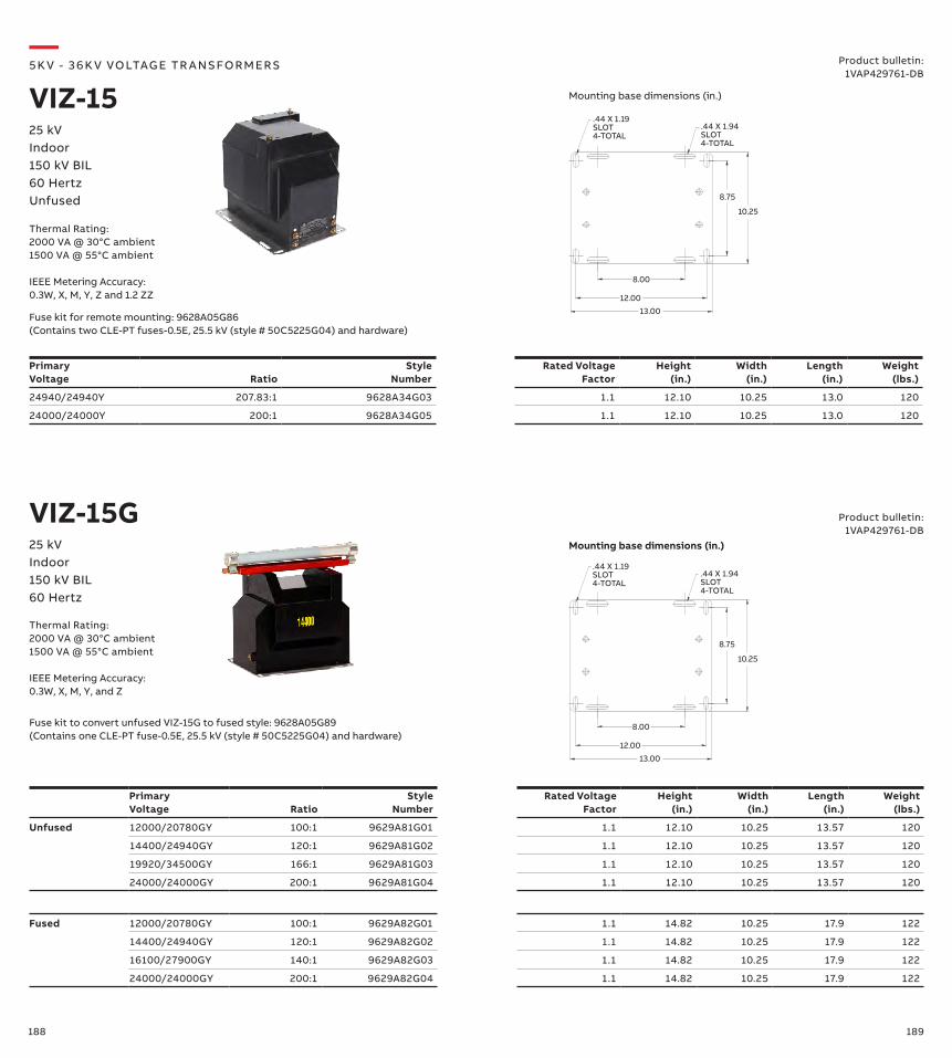
188 189
Primary Voltage Ratio
Style Number
Rated Voltage Factor
Height (in.)
Width (in.)
Length (in.)
Weight (lbs.)
24940/24940Y 207.83:1 9628A34G03 1.1 12.10 10.25 13.0 120
24000/24000Y 200:1 9628A34G05 1.1 12.10 10.25 13.0 120
Primary Voltage Ratio
Style Number
Rated Voltage Factor
Height (in.)
Width (in.)
Length (in.)
Weight (lbs.)
Unfused 12000/20780GY 100:1 9629A81G01 1.1 12.10 10.25 13.57 120
14400/24940GY 120:1 9629A81G02 1.1 12.10 10.25 13.57 120
19920/34500GY 166:1 9629A81G03 1.1 12.10 10.25 13.57 120
24000/24000GY 200:1 9629A81G04 1.1 12.10 10.25 13.57 120
Fused 12000/20780GY 100:1 9629A82G01 1.1 14.82 10.25 17.9 122
14400/24940GY 120:1 9629A82G02 1.1 14.82 10.25 17.9 122
16100/27900GY 140:1 9629A82G03 1.1 14.82 10.25 17.9 122
24000/24000GY 200:1 9629A82G04 1.1 14.82 10.25 17.9 122
13.00
12.00
8.00
10.25
8.75
.44 X 1.94SLOT4-TOTAL
.44 X 1.19SLOT4-TOTAL
13.00
12.00
8.00
10.25
8.75
.44 X 1.94SLOT4-TOTAL
.44 X 1.19SLOT4-TOTAL
VIZ-15G
—5K V - 3 6 K V VO LTAG E TR A NS FO R M ER S
VIZ-15
Fuse kit for remote mounting: 9628A05G86 (Contains two CLE-PT fuses-0.5E, 25.5 kV (style # 50C5225G04) and hardware)
25 kVIndoor150 kV BIL60 HertzUnfused
Product bulletin:1VAP429761-DB
Fuse kit to convert unfused VIZ-15G to fused style: 9628A05G89 (Contains one CLE-PT fuse-0.5E, 25.5 kV (style # 50C5225G04) and hardware)
25 kVIndoor150 kV BIL60 Hertz
Product bulletin:1VAP429761-DB
Thermal Rating:2000 VA @ 30°C ambient1500 VA @ 55°C ambient
IEEE Metering Accuracy: 0.3W, X, M, Y, Z and 1.2 ZZ
Thermal Rating:2000 VA @ 30°C ambient1500 VA @ 55°C ambient
IEEE Metering Accuracy: 0.3W, X, M, Y, and Z
Mounting base dimensions (in.)
Mounting base dimensions (in.)
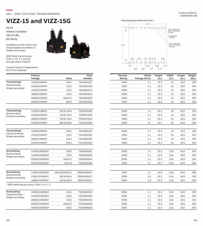
190 191
One bushingStud terminalDouble secondary
11500/20000GY 166.67&166.67:1 7883A29G03* 1000 1.2 22.3 15.6 18.6 205
13800/23900GY 200 & 200:1 7883A29G02* 2000 1.9 22.3 15.6 18.6 205
16800/29100GY 140 & 240:1 7883A29G01* 3000 1.9 22.3 15.6 18.6 205
Primary Voltage
Ratio
Style Number
Thermal Rating
Rated Voltage Factor
Height (in.)
Width (in.)
Length (in.)
Weight (lbs.)
Two bushings Stud terminal Single secondary
12000/20800Y 100:1 7525A81G01 3000 1.1 22.3 16 18.6 205
14400/24940Y 120:1 7525A81G02 3000 1.1 22.3 16 18.6 205
15600/15600Y 130:1 7525A81G12 3000 1.1 22.3 16 18.6 205
18000/18000Y 150:1 7525A81G03 3000 1.1 22.3 16 18.6 205
20000/20000Y 166.67:1 7525A81G05 3000 1.1 22.3 16 18.6 205
24000/24000Y 200:1 7525A81G04 3000 1.1 22.3 16 18.6 205
Two bushings Stud terminal Double secondary
12000/20800Y 100 & 100:1 7526A47G02 3000 1.1 22.3 16 18.6 205
14400/24940Y 120 & 120:1 7526A47G03 3000 1.1 22.3 16 18.6 205
18000/18000Y 150 & 150:1 7526A47G04 3000 1.1 22.3 16 18.6 205
24000/24000Y 200 & 200:1 7526A47G05 3000 1.1 22.3 16 18.6 205
.75 .75
1.75
1.25 1.25
1.25
1.25
1.25 1.25
1.38
.50
.75 1.13
.44
14.50
.44
15.00
.438 x 1.688 SLOTWITH .219 RADIUS6-TOTAL
Ø.438 HOLE6-TOTAL
.438 x .938 SLOTWITH .219 RADIUS4-TOTAL
.50
Two bushings Clamp terminals Single secondary
12000/20800Y 100:1 7525A82G01 3000 1.1 22.3 16 18.6 205
14400/24940Y 120:1 7525A82G02 3000 1.1 22.3 16 18.6 205
18000/18000Y 150:1 7525A82G03 3000 1.1 22.3 16 18.6 205
24000/24000Y 200:1 7525A82G04 3000 1.1 22.3 16 18.6 205
One bushingStud terminalSingle secondary
12000/20800GY 100:1 7525A83G01 3000 1.1 22.3 15.6 18.6 205
14400/24940GY 120:1 7525A83G02 3000 1.1 22.3 15.6 18.6 205
20000/20000GY 166.67:1 7525A83G04 3000 1.1 22.3 15.6 18.6 205
22000/22000GY 183.3:1 7525A83G06 3000 1.1 22.3 15.6 18.6 205
One bushingClamp terminalSingle secondary
12000/20800GY 100:1 7525A84G01 3000 1.1 22.3 15.6 18.6 205
14400/24940GY 120:1 7525A84G02 3000 1.1 22.3 15.6 18.6 205
18000/18000GY 150:1 7525A84G05 3000 1.1 22.3 15.6 18.6 205
20000/20000GY 166.67:1 7525A84G03 3000 1.1 22.3 15.6 18.6 205
24000/24000GY 200:1 7525A84G04 3000 1.1 22.3 15.6 18.6 205
* IEEE metering accuracy: 0.3W, X, M, Y, Z
—5K V - 3 6 K V VO LTAG E TR A NS FO R M ER S
VIZZ-15 and VIZZ-15G25 kVIndoor/outdoor150 kV BIL60 Hertz
Product bulletin:1VAP429591-DB
Available at other ratios and single tapped secondary or double secondary
IEEE Metering Accuracy:0.3W, X, M, Y, Z and ZZ(except where noted*)
Contact factory if replacement for PT-25 is desired
Mounting base dimensions (in.)

192 193
Primary Voltage Ratio
Style Number
IEEE Metering Accuracy
Height (in.)
Width (in.)
Length (in.)
Weight (lbs.)
12000/20780GY 100:1 E-923A592G03 0.3W, X, M, Y 21.39 10.88 17.27 85
13200/22860GY 110:1 E-923A592G04 0.3W, X, M, Y 21.39 10.88 17.27 85
14400/24940GY 120:1 E-923A592G01 0.3W, X, M, Y 21.39 10.88 17.27 85
—5K V - 3 6 K V VO LTAG E TR A NS FO R M ER S
VOG-15R25 kVOutdoor150 kV BIL60 Hertz
Product bulletin:1VAP429804-DB
10.88[276] 10.00
[254]
0.50[13]
1.25[32]
8.63[219]
0.44[11]
L-BRACKETMOUNTINGHOLES
0.44[11]
2.94[75]
4.69[119]
NAMEPLATE MOUNTING
HOLES
11.56[294]
13.31[338]
15.0[381]
8.63[219]
Creep: 38.47" (977 mm)
Thermal Rating:750 VA @ 30°C ambient
Mounting base dimensions (in. [mm])
The VOG-15R is designed with ABB ResiVolt™ technology to withstand fast transient overvoltages.
Also available with stud type primary terminals. Contact your ABB representative.
Note: This unit encapsulated with HCEP material only.
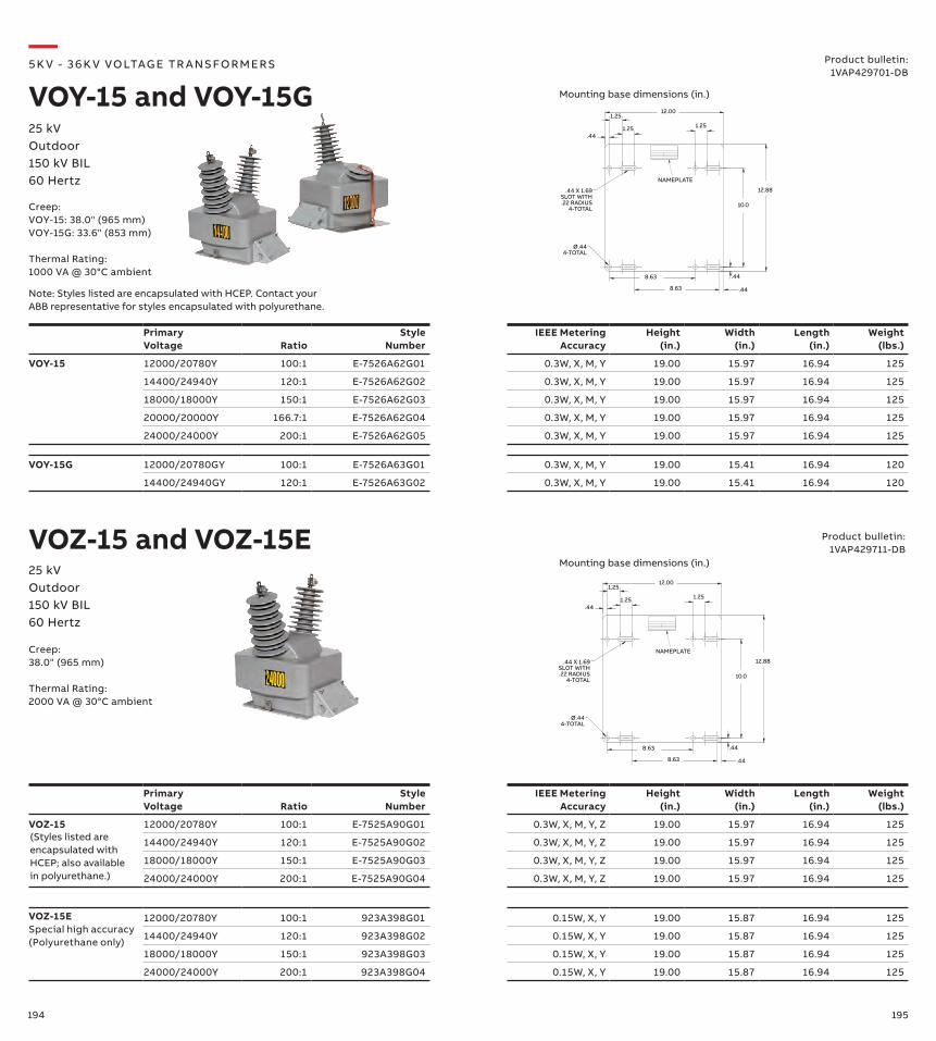
194 195
Primary Voltage Ratio
Style Number
IEEE Metering Accuracy
Height (in.)
Width (in.)
Length (in.)
Weight (lbs.)
VOY-15 12000/20780Y 100:1 E-7526A62G01 0.3W, X, M, Y 19.00 15.97 16.94 125
14400/24940Y 120:1 E-7526A62G02 0.3W, X, M, Y 19.00 15.97 16.94 125
18000/18000Y 150:1 E-7526A62G03 0.3W, X, M, Y 19.00 15.97 16.94 125
20000/20000Y 166.7:1 E-7526A62G04 0.3W, X, M, Y 19.00 15.97 16.94 125
24000/24000Y 200:1 E-7526A62G05 0.3W, X, M, Y 19.00 15.97 16.94 125
Primary Voltage Ratio
Style Number
IEEE Metering Accuracy
Height (in.)
Width (in.)
Length (in.)
Weight (lbs.)
VOZ-15 12000/20780Y 100:1 E-7525A90G01 0.3W, X, M, Y, Z 19.00 15.97 16.94 125
14400/24940Y 120:1 E-7525A90G02 0.3W, X, M, Y, Z 19.00 15.97 16.94 125
18000/18000Y 150:1 E-7525A90G03 0.3W, X, M, Y, Z 19.00 15.97 16.94 125
24000/24000Y 200:1 E-7525A90G04 0.3W, X, M, Y, Z 19.00 15.97 16.94 125
12.00
.441.25
.44
10.0
12.88
1.25
.44 X 1.69SLOT WITH.22 RADIUS
4-TOTAL
Ø.44 4-TOTAL
1.25
.44
NAMEPLATE
8.63
8.63
VOY-15G 12000/20780GY 100:1 E-7526A63G01 0.3W, X, M, Y 19.00 15.41 16.94 120
14400/24940GY 120:1 E-7526A63G02 0.3W, X, M, Y 19.00 15.41 16.94 120
VOZ-15ESpecial high accuracy(Polyurethane only)
12000/20780Y 100:1 923A398G01 0.15W, X, Y 19.00 15.87 16.94 125
14400/24940Y 120:1 923A398G02 0.15W, X, Y 19.00 15.87 16.94 125
18000/18000Y 150:1 923A398G03 0.15W, X, Y 19.00 15.87 16.94 125
24000/24000Y 200:1 923A398G04 0.15W, X, Y 19.00 15.87 16.94 125
VOZ-15 and VOZ-15E
—5K V - 3 6 K V VO LTAG E TR A NS FO R M ER S
VOY-15 and VOY-15G25 kVOutdoor150 kV BIL60 Hertz
Product bulletin:1VAP429701-DB
Product bulletin:1VAP429711-DB
12.00
.441.25
.44
10.0
12.88
1.25
.44 X 1.69SLOT WITH.22 RADIUS
4-TOTAL
Ø.44 4-TOTAL
1.25
.44
NAMEPLATE
8.63
8.63
25 kVOutdoor150 kV BIL60 Hertz
Creep:VOY-15: 38.0" (965 mm)VOY-15G: 33.6" (853 mm)
Thermal Rating:1000 VA @ 30°C ambient
Creep:38.0" (965 mm)
Thermal Rating:2000 VA @ 30°C ambient
Mounting base dimensions (in.)
Mounting base dimensions (in.)
Note: Styles listed are encapsulated with HCEP. Contact your ABB representative for styles encapsulated with polyurethane.
(Styles listed are encapsulated with HCEP; also available in polyurethane.)
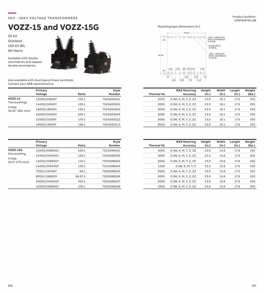
196 197
Primary Voltage Ratio
Style Number Thermal VA
IEEE Metering Accuracy
Height (in.)
Width (in.)
Length (in.)
Weight (lbs.)
VOZZ-15G One bushing
12000/20800GY 100:1 7525A98G01 3000 0.3W, X, M, Y, Z, ZZ 23.0 15.6 17.6 202
14400/24940GY 120:1 7525A98G02 3000 0.3W, X, M, Y, Z, ZZ 23.0 15.6 17.6 202
13200/22860GY 110:1 7525A98G03 3000 0.3W, X, M, Y, Z, ZZ 23.0 15.6 17.6 202
14400/24940GY 120:1 7525A98G04 1200 0.3W, X, M, Y, Z 23.0 15.6 17.6 202
7200/12470GY 60:1 7525A98G05 3000 0.3W, X, M, Y, Z, ZZ 23.0 15.6 17.6 202
8000/13860GY 66.67:1 7525A98G06 3000 0.3W, X, M, Y, Z, ZZ 23.0 15.6 17.6 202
24000/24000GY 200:1 7525A98G07 3000 0.3W, X, M, Y, Z, ZZ 23.0 15.6 17.6 202
12000/20800GY 100:1 7525A98G08 1000 0.3W, X, M, Y, Z, ZZ 23.0 15.6 17.6 202
Primary Voltage Ratio
Style Number Thermal VA
IEEE Metering Accuracy
Height (in.)
Width (in.)
Length (in.)
Weight (lbs.)
VOZZ-15 Two bushings
12000/20800Y 100:1 7525A93G01 3000 0.3W, X, M, Y, Z, ZZ 23.0 16.1 17.6 205
14400/24940Y 120:1 7525A93G02 3000 0.3W, X, M, Y, Z, ZZ 23.0 16.1 17.6 205
18000/18000Y 150:1 7525A93G03 3000 0.3W, X, M, Y, Z, ZZ 23.0 16.1 17.6 205
24000/24000Y 200:1 7525A93G04 3000 0.3W, X, M, Y, Z, ZZ 23.0 16.1 17.6 205
21000/21000Y 175:1 7525A93G12 3000 0.3W, X, M, Y, Z, ZZ 23.0 16.1 17.6 205
19920/19920Y 166:1 7525A93G13 3000 0.3W, X, M, Y, Z, ZZ 23.0 16.1 17.6 205
.75 .75
1.75
1.25 1.25
1.25
1.25
1.25 1.25
1.38
.50
.75 1.13
.44
14.50
.44
15.00
.438 x 1.688 SLOTWITH .219 RADIUS6-TOTAL
Ø.438 HOLE6-TOTAL
.438 x .938 SLOTWITH .219 RADIUS4-TOTAL
.50
Also available with stud type primary terminals. Contact your ABB representative.
—5K V - 3 6 K V VO LTAG E TR A NS FO R M ER S
VOZZ-15 and VOZZ-15G25 kVOutdoor150 kV BIL60 Hertz
Product bulletin:1VAP429781-DB
Available with double secondaries and tapped double secondaries.
Mounting base dimensions (in.)
Creep:36.25" (921 mm)
Creep:30.5" (775 mm)
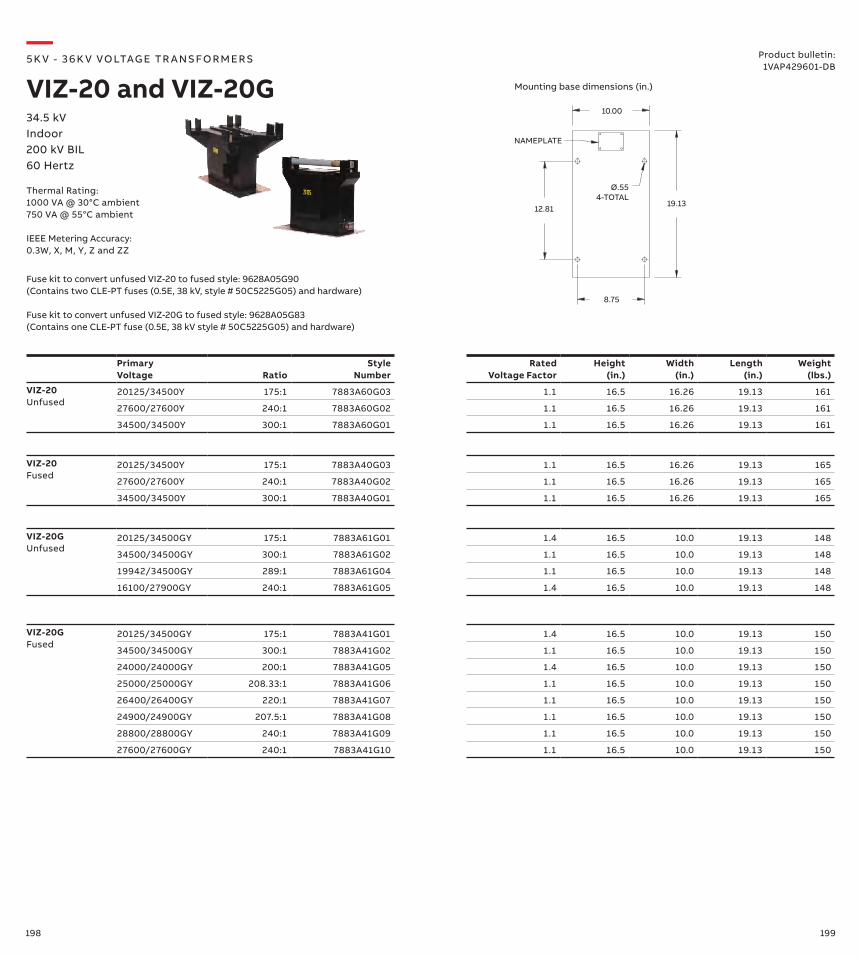
198 199
VIZ-20GUnfused
20125/34500GY 175:1 7883A61G01 1.4 16.5 10.0 19.13 148
34500/34500GY 300:1 7883A61G02 1.1 16.5 10.0 19.13 148
19942/34500GY 289:1 7883A61G04 1.1 16.5 10.0 19.13 148
16100/27900GY 240:1 7883A61G05 1.4 16.5 10.0 19.13 148
Primary Voltage
Ratio
Style Number
Rated Voltage Factor
Height (in.)
Width (in.)
Length (in.)
Weight (lbs.)
VIZ-20Unfused
20125/34500Y 175:1 7883A60G03 1.1 16.5 16.26 19.13 161
27600/27600Y 240:1 7883A60G02 1.1 16.5 16.26 19.13 161
34500/34500Y 300:1 7883A60G01 1.1 16.5 16.26 19.13 161
VIZ-20Fused
20125/34500Y 175:1 7883A40G03 1.1 16.5 16.26 19.13 165
27600/27600Y 240:1 7883A40G02 1.1 16.5 16.26 19.13 165
34500/34500Y 300:1 7883A40G01 1.1 16.5 16.26 19.13 165
VIZ-20GFused
20125/34500GY 175:1 7883A41G01 1.4 16.5 10.0 19.13 150
34500/34500GY 300:1 7883A41G02 1.1 16.5 10.0 19.13 150
24000/24000GY 200:1 7883A41G05 1.4 16.5 10.0 19.13 150
25000/25000GY 208.33:1 7883A41G06 1.1 16.5 10.0 19.13 150
26400/26400GY 220:1 7883A41G07 1.1 16.5 10.0 19.13 150
24900/24900GY 207.5:1 7883A41G08 1.1 16.5 10.0 19.13 150
28800/28800GY 240:1 7883A41G09 1.1 16.5 10.0 19.13 150
27600/27600GY 240:1 7883A41G10 1.1 16.5 10.0 19.13 150
10.00
19.13
8.75
12.81
NAMEPLATE
Ø.554-TOTAL
—5K V - 3 6 K V VO LTAG E TR A NS FO R M ER S
VIZ-20 and VIZ-20G
Fuse kit to convert unfused VIZ-20 to fused style: 9628A05G90 (Contains two CLE-PT fuses (0.5E, 38 kV, style # 50C5225G05) and hardware)
Fuse kit to convert unfused VIZ-20G to fused style: 9628A05G83 (Contains one CLE-PT fuse (0.5E, 38 kV style # 50C5225G05) and hardware)
34.5 kVIndoor200 kV BIL60 Hertz
Product bulletin:1VAP429601-DB
Thermal Rating:1000 VA @ 30°C ambient750 VA @ 55°C ambient
IEEE Metering Accuracy: 0.3W, X, M, Y, Z and ZZ
Mounting base dimensions (in.)
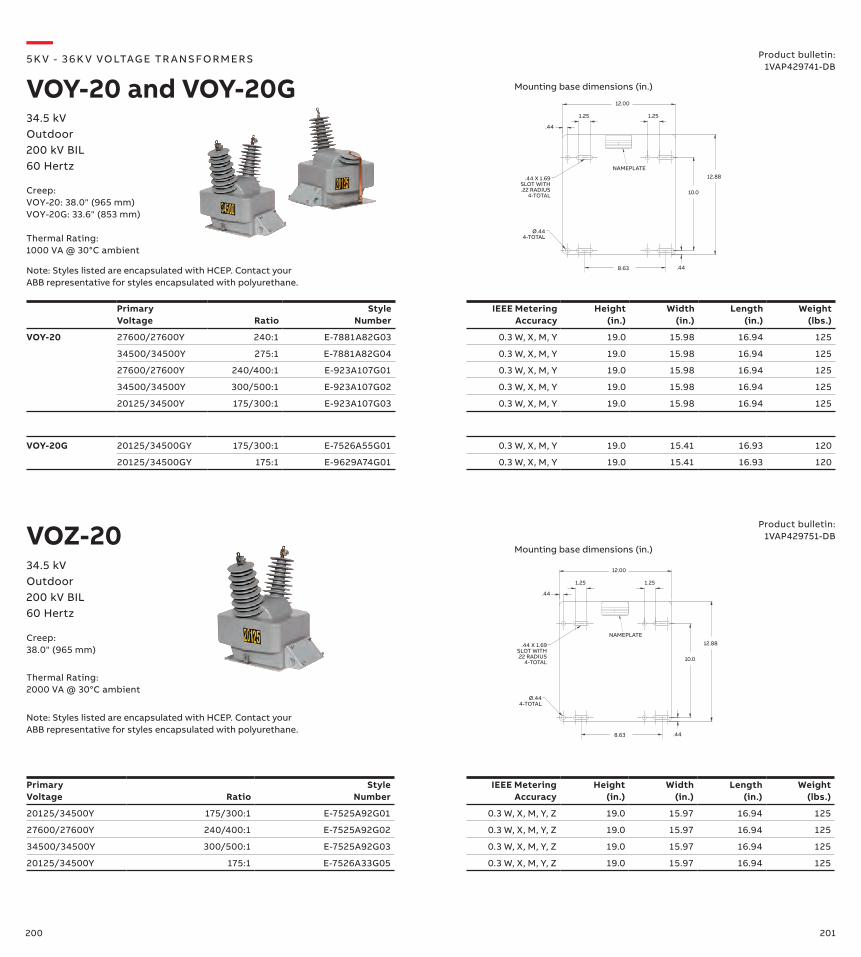
200 201
12.00
.44
1.25
.44
10.0
12.88
1.25
.44 X 1.69SLOT WITH.22 RADIUS
4-TOTAL
Ø.444-TOTAL
NAMEPLATE
8.63
Primary Voltage Ratio
Style Number
IEEE Metering Accuracy
Height (in.)
Width (in.)
Length (in.)
Weight (lbs.)
VOY-20 27600/27600Y 240:1 E-7881A82G03 0.3 W, X, M, Y 19.0 15.98 16.94 125
34500/34500Y 275:1 E-7881A82G04 0.3 W, X, M, Y 19.0 15.98 16.94 125
27600/27600Y 240/400:1 E-923A107G01 0.3 W, X, M, Y 19.0 15.98 16.94 125
34500/34500Y 300/500:1 E-923A107G02 0.3 W, X, M, Y 19.0 15.98 16.94 125
20125/34500Y 175/300:1 E-923A107G03 0.3 W, X, M, Y 19.0 15.98 16.94 125
VOY-20G 20125/34500GY 175/300:1 E-7526A55G01 0.3 W, X, M, Y 19.0 15.41 16.93 120
20125/34500GY 175:1 E-9629A74G01 0.3 W, X, M, Y 19.0 15.41 16.93 120
—5K V - 3 6 K V VO LTAG E TR A NS FO R M ER S
VOY-20 and VOY-20G34.5 kVOutdoor200 kV BIL60 Hertz
Product bulletin:1VAP429741-DB
Primary Voltage Ratio
Style Number
IEEE Metering Accuracy
Height (in.)
Width (in.)
Length (in.)
Weight (lbs.)
20125/34500Y 175/300:1 E-7525A92G01 0.3 W, X, M, Y, Z 19.0 15.97 16.94 125
27600/27600Y 240/400:1 E-7525A92G02 0.3 W, X, M, Y, Z 19.0 15.97 16.94 125
34500/34500Y 300/500:1 E-7525A92G03 0.3 W, X, M, Y, Z 19.0 15.97 16.94 125
20125/34500Y 175:1 E-7526A33G05 0.3 W, X, M, Y, Z 19.0 15.97 16.94 125
VOZ-2034.5 kVOutdoor200 kV BIL60 Hertz
Product bulletin:1VAP429751-DB
12.00
.44
1.25
.44
10.0
12.88
1.25
.44 X 1.69SLOT WITH.22 RADIUS
4-TOTAL
Ø.444-TOTAL
NAMEPLATE
8.63
Creep:VOY-20: 38.0" (965 mm)VOY-20G: 33.6" (853 mm)
Thermal Rating:1000 VA @ 30°C ambient
Creep:38.0" (965 mm)
Thermal Rating:2000 VA @ 30°C ambient
Mounting base dimensions (in.)
Mounting base dimensions (in.)
Note: Styles listed are encapsulated with HCEP. Contact your ABB representative for styles encapsulated with polyurethane.
Note: Styles listed are encapsulated with HCEP. Contact your ABB representative for styles encapsulated with polyurethane.
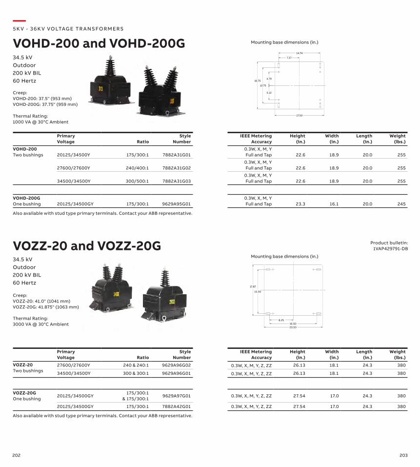
202 203
VOZZ-20G One bushing
20125/34500GY175/300:1
& 175/300:19629A97G01 0.3W, X, M, Y, Z, ZZ 27.54 17.0 24.3 380
20125/34500GY 175/300:1 7882A42G01 0.3W, X, M, Y, Z, ZZ 27.54 17.0 24.3 380
Primary Voltage Ratio
Style Number
IEEE Metering Accuracy
Height (in.)
Width (in.)
Length (in.)
Weight (lbs.)
VOHD-200Two bushings 20125/34500Y 175/300:1 7882A31G01
0.3W, X, M, YFull and Tap 22.6 18.9 20.0 255
27600/27600Y 240/400:1 7882A31G020.3W, X, M, YFull and Tap 22.6 18.9 20.0 255
34500/34500Y 300/500:1 7882A31G030.3W, X, M, YFull and Tap 22.6 18.9 20.0 255
VOHD-200GOne bushing 20125/34500GY 175/300:1 9629A95G01
0.3W, X, M, YFull and Tap 23.3 16.1 20.0 245
7.37
14.74
5.12
4.79
12.75
16.75
17.50
Primary Voltage Ratio
Style Number
IEEE Metering Accuracy
Height (in.)
Width (in.)
Length (in.)
Weight (lbs.)
VOZZ-20 Two bushings
27600/27600Y 240 & 240:1 9629A96G02 0.3W, X, M, Y, Z, ZZ 26.13 18.1 24.3 380
34500/34500Y 300 & 300:1 9629A96G01 0.3W, X, M, Y, Z, ZZ 26.13 18.1 24.3 380
15.50
17.87
8.2516.5020.50
VOZZ-20 and VOZZ-20G
—5K V - 3 6 K V VO LTAG E TR A NS FO R M ER S
VOHD-200 and VOHD-200G34.5 kVOutdoor200 kV BIL60 Hertz
34.5 kVOutdoor200 kV BIL60 Hertz
Product bulletin:1VAP429791-DB
Creep:VOHD-200: 37.5" (953 mm)VOHD-200G: 37.75" (959 mm)
Thermal Rating:1000 VA @ 30°C Ambient
Creep:VOZZ-20: 41.0" (1041 mm)VOZZ-20G: 41.875" (1063 mm)
Thermal Rating:3000 VA @ 30°C Ambient
Mounting base dimensions (in.)
Mounting base dimensions (in.)
Also available with stud type primary terminals. Contact your ABB representative.
Also available with stud type primary terminals. Contact your ABB representative.
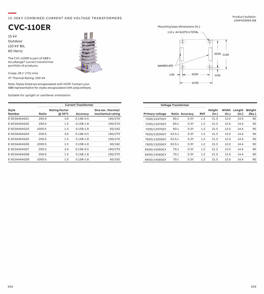
204 205
Style Number Ratio
Rating Factor @ 30°C Accuracy
One sec. thermal/ mechanical rating Primary voltage Ratio Accuracy RVF
Height (in.)
Width (in.)
Length (in.)
Weight (lbs.)
E-923A464G01 200:5 3.0 0.15B-0.5 190/270 7200/12470GY 60:1 0.3Y 1.2 21.5 12.0 14.4 90
E-923A464G02 200:5 1.5 0.15B-1.8 190/270 7200/12470GY 60:1 0.3Y 1.2 21.5 12.0 14.4 90
E-923A464G03 1000:5 1.5 0.15B-1.8 60/162 7200/12470GY 60:1 0.3Y 1.2 21.5 12.0 14.4 90
E-923A464G04 200:5 3.0 0.15B-0.5 190/270 7620/13200GY 63.5:1 0.3Y 1.2 21.5 12.0 14.4 90
E-923A464G05 200:5 1.5 0.15B-1.8 190/270 7620/13200GY 63.5:1 0.3Y 1.2 21.5 12.0 14.4 90
E-923A464G06 1000:5 1.5 0.15B-1.8 60/162 7620/13200GY 63.5:1 0.3Y 1.2 21.5 12.0 14.4 90
E-923A464G07 200:5 3.0 0.15B-0.5 190/270 8400/14560GY 70:1 0.3Y 1.2 21.5 12.0 14.4 90
E-923A464G08 200:5 1.5 0.15B-1.8 190/270 8400/14560GY 70:1 0.3Y 1.2 21.5 12.0 14.4 90
E-923A464G09 1000:5 1.5 0.15B-1.8 60/162 8400/14560GY 70:1 0.3Y 1.2 21.5 12.0 14.4 90
Voltage Transformer
10.001.00
12.00
0.50
10.00 11.00
1.13 x .44 SLOTS 4-TOTAL
NAMEPLATE
Current Transformer
Creep: 28.1" (715 mm)
VT Thermal Rating: 500 VA
Note: Styles listed are encapsulated with HCEP. Contact your ABB representative for styles encapsulated with polyurethane.
—1 5 -3 6 K V CO M B I N ED CU R R ENT A N D VO LTAG E TR A NS FO R M ER S
CVC-110ER15 kVOutdoor110 kV BIL60 Hertz
Product bulletin:1VAP429993-DB
Mounting base dimensions (in.)
The CVC-110ER is part of ABB’s AccuRange® current transformer portfolio of products.
Suitable for upright or cantilever orientation.
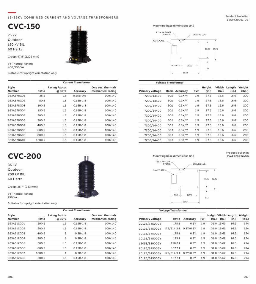
206 207
16.63
10.00
10.00 12.25
NAMEPLATE
5.631.25
GROUND LUG1.13 x .44 SLOTS
4-TOTAL
CVC-200
15.62
10.00
10.00 12.25
NAMEPLATE
4.621.12
GROUND LUG1.13 x .44 SLOTS
4-TOTAL
—1 5 -3 6 K V CO M B I N ED CU R R ENT A N D VO LTAG E TR A NS FO R M ER S
CVC-15025 kVOutdoor150 kV BIL60 Hertz
Product bulletin:1VAP429991-DB
36 kVOutdoor200 kV BIL60 Hertz
Product bulletin:1VAP429996-DB
Creep: 47.5" (1209 mm)
VT Thermal Rating:400/750 VA
Mounting base dimensions (in.)
Mounting base dimensions (in.)
Style Number Ratio
Rating Factor @ 30°C Accuracy
One sec. thermal/ mechanical rating Primary voltage Ratio Accuracy RVF
Height (in.)
Width (in.)
Length (in.)
Weight (lbs.)
923A578G01 25:5 1.5 0.15B-0.9 100/140 7200/14400 60:1 0.3X/Y 1.9 27.5 16.6 16.6 200
923A578G02 50:5 1.5 0.15B-1.8 100/140 7200/14400 60:1 0.3X/Y 1.9 27.5 16.6 16.6 200
923A578G03 100:5 1.5 0.15B-1.8 100/140 7200/14400 60:1 0.3X/Y 1.9 27.5 16.6 16.6 200
923A578G04 150:5 1.5 0.15B-1.8 100/140 7200/14400 60:1 0.3X/Y 1.9 27.5 16.6 16.6 200
923A578G05 200:5 1.5 0.15B-1.8 100/140 7200/14400 60:1 0.3X/Y 1.9 27.5 16.6 16.6 200
923A578G06 300:5 1.5 0.15B-1.8 100/140 7200/14400 60:1 0.3X/Y 1.9 27.5 16.6 16.6 200
923A578G07 400:5 1.5 0.15B-1.8 100/140 7200/14400 60:1 0.3X/Y 1.9 27.5 16.6 16.6 200
923A578G08 600:5 1.5 0.15B-1.8 100/140 7200/14400 60:1 0.3X/Y 1.9 27.5 16.6 16.6 200
923A578G09 800:5 1.5 0.15B-1.8 100/140 7200/14400 60:1 0.3X/Y 1.9 27.5 16.6 16.6 200
923A578G10 1200:5 1.5 0.15B-1.8 100/140 7200/14400 60:1 0.3X/Y 1.9 27.5 16.6 16.6 200
Voltage TransformerCurrent Transformer
Style Number Ratio
Rating Factor @ 30°C Accuracy
One sec. thermal/ mechanical rating Primary voltage Ratio Accuracy RVF
Height (in.)
Width (in.)
Length (in.)
Weight (lbs.)
923A512G01 200:5 1.5 0.15B-1.8 100/140 20125/34500GY 175:1 0.3Y 1.9 31.0 15.62 16.6 274
923A512G02 200:5 1.5 0.15B-1.8 100/140 20125/34500GY 175/514.3:1 0.3Y/0.3Y 1.9 31.0 15.62 16.6 274
923A512G03 400:5 2 0.3B-1.8 100/140 20125/34500GY 175:1 0.3Y 1.9 31.0 15.62 16.6 274
923A512G04 300:5 3 0.3B-1.8 100/140 20125/34500GY 175:1 0.3Y 1.9 31.0 15.62 16.6 274
923A512G05 200:5 1.5 0.15B-1.8 100/140 19053/33000GY 158.7:1 0.3Y 1.9 31.0 15.62 16.6 274
923A512G06 600:5 1.5 0.15B-1.8 100/140 20125/34500GY 167.7:1 0.3Y 1.9 31.0 15.62 16.6 274
923A512G07 1600:5 1 0.3B-1.8 100/140 20125/34500GY 175/514.3:1 0.3Y/0.3Y 1.9 31.0 15.62 16.6 274
923A512G08 200:5 1.5 0.15B-1.8 100/140 20125/34500GY 167.7:1 0.3Y 1.9 31.0 15.62 16.6 274
Voltage TransformerCurrent Transformer
Creep: 38.7" (983 mm)
VT Thermal Rating:750 VA
Suitable for upright orientation only.
Suitable for upright orientation only.
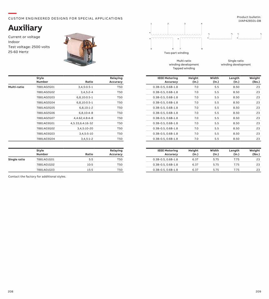
208 209
Style Number Ratio
RelayingAccuracy
IEEE MeteringAccuracy
Height (in.)
Width (in.)
Length (in.)
Weight (lbs.)
Multi-ratio 7881A02G01 3,4,5:0.5-1 T50 0.3B-0.5, 0.6B-1.8 7.0 5.5 8.50 23
7881A02G02 3,4,5:2-4 T50 0.3B-0.5, 0.6B-1.8 7.0 5.5 8.50 23
7881A02G03 6,8,10:0.5-1 T50 0.3B-0.5, 0.6B-1.8 7.0 5.5 8.50 23
7881A02G04 6,8,10:0.5-1 T50 0.3B-0.5, 0.6B-1.8 7.0 5.5 8.50 23
7881A02G05 6,8,10:1-2 T50 0.3B-0.5, 0.6B-1.8 7.0 5.5 8.50 23
7881A02G06 6,8,10:4-8 T50 0.3B-0.5, 0.6B-1.8 7.0 5.5 8.50 23
7881A02G07 4,4.62,4.8:4-8 T50 0.3B-0.5, 0.6B-1.8 7.0 5.5 8.50 23
7881A03G01 4,5.33,6.4:16-32 T50 0.3B-0.5, 0.6B-1.8 7.0 5.5 8.50 23
7881A03G02 3,4,5:10-20 T50 0.3B-0.5, 0.6B-1.8 7.0 5.5 8.50 23
7881A03G03 3,4,5:5-10 T50 0.3B-0.5, 0.6B-1.8 7.0 5.5 8.50 23
7881A03G04 3,4,5:1-2 T50 0.3B-0.5, 0.6B-1.8 7.0 5.5 8.50 23
Style Number Ratio
RelayingAccuracy
IEEE MeteringAccuracy
Height (in.)
Width (in.)
Length (in.)
Weight (lbs.)
Single ratio 7881A01G01 5:5 T50 0.3B-0.5, 0.6B-1.8 6.37 5.75 7.75 23
7881A01G02 10:5 T50 0.3B-0.5, 0.6B-1.8 6.37 5.75 7.75 23
7881A01G03 15:5 T50 0.3B-0.5, 0.6B-1.8 6.37 5.75 7.75 23
Multi-ratio winding development
Tapped winding
Single ratio winding development
Contact the factory for additional styles.
Two-part winding
1 2 3 4
5 6 7 8
H1 X2X1H2
—CUS TO M ENG I N EER ED DE S I G NS FO R S PECI A L A PPLI C ATI O NS
AuxiliaryCurrent or voltageIndoorTest voltage: 2500 volts25-60 Hertz
Product bulletin:1VAP428501-DB
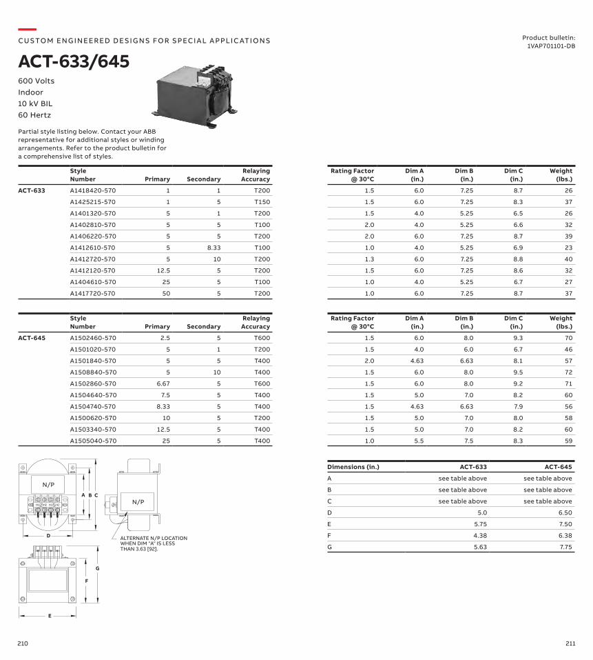
210 211
Style Number Primary Secondary
RelayingAccuracy
Rating Factor @ 30°C
Dim A (in.)
Dim B (in.)
Dim C (in.)
Weight (lbs.)
ACT-633 A1418420-570 1 1 T200 1.5 6.0 7.25 8.7 26
A1425215-570 1 5 T150 1.5 6.0 7.25 8.3 37
A1401320-570 5 1 T200 1.5 4.0 5.25 6.5 26
A1402810-570 5 5 T100 2.0 4.0 5.25 6.6 32
A1406220-570 5 5 T200 2.0 6.0 7.25 8.7 39
A1412610-570 5 8.33 T100 1.0 4.0 5.25 6.9 23
A1412720-570 5 10 T200 1.3 6.0 7.25 8.8 40
A1412120-570 12.5 5 T200 1.5 6.0 7.25 8.6 32
A1404610-570 25 5 T100 1.0 4.0 5.25 6.7 27
A1417720-570 50 5 T200 1.0 6.0 7.25 8.7 37
Dimensions (in.) ACT-633 ACT-645
A see table above see table above
B see table above see table above
C see table above see table above
D 5.0 6.50
E 5.75 7.50
F 4.38 6.38
G 5.63 7.75
A B C
D
F
G
E
N/P
ALTERNATE N/P LOCATIONWHEN DIM "A" IS LESS
N/P
THAN 3.63 [92].
H1 H2 X1 X2
—CUS TO M ENG I N EER ED DE S I G NS FO R S PECI A L A PPLI C ATI O NS
ACT-633/645600 Volts Indoor 10 kV BIL60 Hertz
Product bulletin:1VAP701101-DB
Style Number Primary Secondary
RelayingAccuracy
Rating Factor @ 30°C
Dim A (in.)
Dim B (in.)
Dim C (in.)
Weight (lbs.)
ACT-645 A1502460-570 2.5 5 T600 1.5 6.0 8.0 9.3 70
A1501020-570 5 1 T200 1.5 4.0 6.0 6.7 46
A1501840-570 5 5 T400 2.0 4.63 6.63 8.1 57
A1508840-570 5 10 T400 1.5 6.0 8.0 9.5 72
A1502860-570 6.67 5 T600 1.5 6.0 8.0 9.2 71
A1504640-570 7.5 5 T400 1.5 5.0 7.0 8.2 60
A1504740-570 8.33 5 T400 1.5 4.63 6.63 7.9 56
A1500620-570 10 5 T200 1.5 5.0 7.0 8.0 58
A1503340-570 12.5 5 T400 1.5 5.0 7.0 8.2 60
A1505040-570 25 5 T400 1.0 5.5 7.5 8.3 59
Partial style listing below. Contact your ABB representative for additional styles or winding arrangements. Refer to the product bulletin for a comprehensive list of styles.
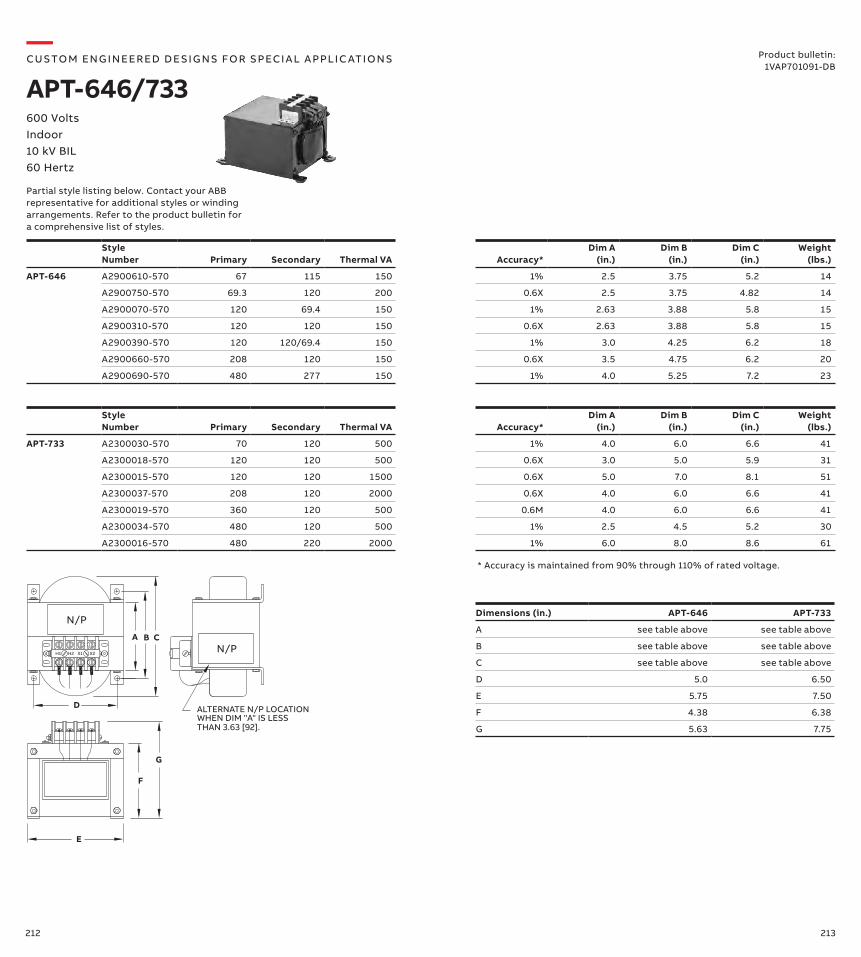
212 213
Dimensions (in.) APT-646 APT-733
A see table above see table above
B see table above see table above
C see table above see table above
D 5.0 6.50
E 5.75 7.50
F 4.38 6.38
G 5.63 7.75
A B C
D
F
G
E
N/P
ALTERNATE N/P LOCATIONWHEN DIM "A" IS LESS
N/P
THAN 3.63 [92].
H1 H2 X1 X2
* Accuracy is maintained from 90% through 110% of rated voltage.
—CUS TO M ENG I N EER ED DE S I G NS FO R S PECI A L A PPLI C ATI O NS
APT-646/733600 Volts Indoor 10 kV BIL60 Hertz
Product bulletin:1VAP701091-DB
Style Number Primary Secondary Thermal VA Accuracy*
Dim A (in.)
Dim B (in.)
Dim C (in.)
Weight (lbs.)
APT-646 A2900610-570 67 115 150 1% 2.5 3.75 5.2 14
A2900750-570 69.3 120 200 0.6X 2.5 3.75 4.82 14
A2900070-570 120 69.4 150 1% 2.63 3.88 5.8 15
A2900310-570 120 120 150 0.6X 2.63 3.88 5.8 15
A2900390-570 120 120/69.4 150 1% 3.0 4.25 6.2 18
A2900660-570 208 120 150 0.6X 3.5 4.75 6.2 20
A2900690-570 480 277 150 1% 4.0 5.25 7.2 23
Style Number Primary Secondary Thermal VA Accuracy*
Dim A (in.)
Dim B (in.)
Dim C (in.)
Weight (lbs.)
APT-733 A2300030-570 70 120 500 1% 4.0 6.0 6.6 41
A2300018-570 120 120 500 0.6X 3.0 5.0 5.9 31
A2300015-570 120 120 1500 0.6X 5.0 7.0 8.1 51
A2300037-570 208 120 2000 0.6X 4.0 6.0 6.6 41
A2300019-570 360 120 500 0.6M 4.0 6.0 6.6 41
A2300034-570 480 120 500 1% 2.5 4.5 5.2 30
A2300016-570 480 220 2000 1% 6.0 8.0 8.6 61
Partial style listing below. Contact your ABB representative for additional styles or winding arrangements. Refer to the product bulletin for a comprehensive list of styles.
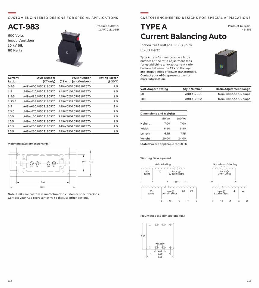
214 215
H1X2 X1 H2
4.50
11.00
8.88
3.00
600 VoltsIndoor/outdoor 10 kV BIL60 Hertz
Note: Units are custom manufactured to customer specifications. Contact your ABB representative to discuss other options.
Product bulletin:1VAP701111-DB
Mounting base dimensions (in.)
Current Ratio
Style Number (CT only)
Style Number (CT with junction box)
Rating Factor @ 30°C
0.5:5 A49W005A050S180570 A49W005A050S18T570 1.5
1:5 A49W010A050S180570 A49W010A050S18T570 1.5
2.5:5 A49W025A050S180570 A49W025A050S18T570 1.5
3.33:5 A49W033A050S180570 A49W033A050S18T570 1.5
5:5 A49W050A050S180570 A49W050A050S18T570 3.0
7.5:5 A49W075A050S180570 A49W075A050S18T570 1.5
10:5 A49W100A050S180570 A49W100A050S18T570 1.5
15:5 A49W150A050S180570 A49W150A050S18T570 1.5
20:5 A49W200A050S180570 A49W200A050S18T570 1.5
25:5 A49W250A050S180570 A49W250A050S18T570 1.5
—CUS TO M ENG I N EER ED DE S I G NS FO R S PECI A L A PPLI C ATI O NS
ACT-983
Volt-Ampere Rating Style Number Ratio Adjustment Range
50 7881A17G01 from 10.8:5 to 5:5 amps
100 7881A17G02 from 10.8:5 to 5:5 amps
Winding Development
Dimensions and Weights
50 VA 100 VA
Height 7.00 7.00
Width 6.50 6.50
Length 6.75 7.75
Weight 20.00 24.00
Mounting base dimensions (in.)
6.50
1.25
2.255.006.75
1 2 6 87
1 2 3 10 1611
9 15 1614
40turns
70 taps @10 turn steps
taps @1 turn steps
95turns
taps @10 turn steps
28 27 taps @ 1 turn steps
4 4
- to -
- to - - to -
Main Winding Buck-Boost Winding
Stated VA are applicable for 60 Hz
—CUS TO M ENG I N EER ED DE S I G NS FO R S PECI A L A PPLI C ATI O NS
TYPE A Current Balancing AutoIndoor test voltage: 2500 volts25-60 Hertz
Type A transformers provide a large number of fine ratio adjustment taps for establishing an exact current ratio balance between the CTs on the input and output sides of power transformers. Contact your ABB representative for more information.
Product bulletin:42-852
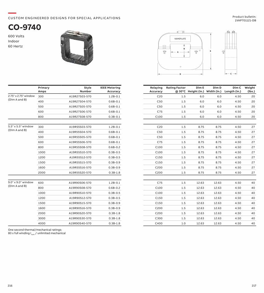
216 217
Primary Amps
Style Number
IEEE Metering Accuracy
Relaying Accuracy
Rating Factor @ 30°C
Dim E Height (in.)
Dim D Width (in.)
Dim C Length (in.)
Weight (lbs.)
2.75" x 2.75" window (Dim A and B)
300 A19R27S03-570 1.2B-0.1 C20 1.5 6.0 6.0 4.50 20
400 A19R27S04-570 0.6B-0.1 C50 1.5 6.0 6.0 4.50 20
500 A19R27S05-570 0.6B-0.1 C50 1.5 6.0 6.0 4.50 20
600 A19R27S06-570 0.6B-0.1 C75 1.5 6.0 6.0 4.50 20
800 A19R27S08-570 0.3B-0.1 C100 1.5 6.0 6.0 4.50 20
5.5" x 5.5" window (Dim A and B)
300 A19R55S03-570 1.2B-0.1 C20 1.5 8.75 8.75 4.50 27
400 A19R55S04-570 0.6B-0.1 C50 1.5 8.75 8.75 4.50 27
500 A19R55S05-570 0.6B-0.1 C50 1.5 8.75 8.75 4.50 27
600 A19R55S06-570 0.6B-0.1 C75 1.5 8.75 8.75 4.50 27
800 A19R55S08-570 0.6B-0.2 C100 1.5 8.75 8.75 4.50 27
1000 A19R55S10-570 0.3B-0.5 C100 1.5 8.75 8.75 4.50 27
1200 A19R55S12-570 0.3B-0.5 C150 1.5 8.75 8.75 4.50 27
1500 A19R55S15-570 0.3B-0.9 C150 1.5 8.75 8.75 4.50 27
1600 A19R55S16-570 0.3B-0.9 C200 1.5 8.75 8.75 4.50 27
2000 A19R55S20-570 0.3B-1.8 C200 1.5 8.75 8.75 4.50 27
9.0" x 9.0" window(Dim A and B)
600 A19R90S06-570 1.2B-0.1 C75 1.5 12.63 12.63 4.50 40
800 A19R90S08-570 0.6B-0.2 C100 1.5 12.63 12.63 4.50 40
1000 A19R90S10-570 0.3B-0.5 C100 1.5 12.63 12.63 4.50 40
1200 A19R90S12-570 0.3B-0.5 C150 1.5 12.63 12.63 4.50 40
1500 A19R90S15-570 0.3B-0.9 C150 1.5 12.63 12.63 4.50 40
1600 A19R90S16-570 0.3B-0.9 C200 1.5 12.63 12.63 4.50 40
2000 A19R90S20-570 0.3B-1.8 C200 1.5 12.63 12.63 4.50 40
3000 A19R90S30-570 0.3B-1.8 C300 1.5 12.63 12.63 4.50 40
4000 A19R90S40-570 0.3B-1.8 C400 1.0 12.63 12.63 4.50 40
D
EA
B
C
NAMEPLATE
One second thermal/mechanical ratings: 80 x full winding Inom / unlimited mechanical
—CUS TO M ENG I N EER ED DE S I G NS FO R S PECI A L A PPLI C ATI O NS
CO-9740600 Volts Indoor 60 Hertz
Product bulletin:1VAP701121-DB
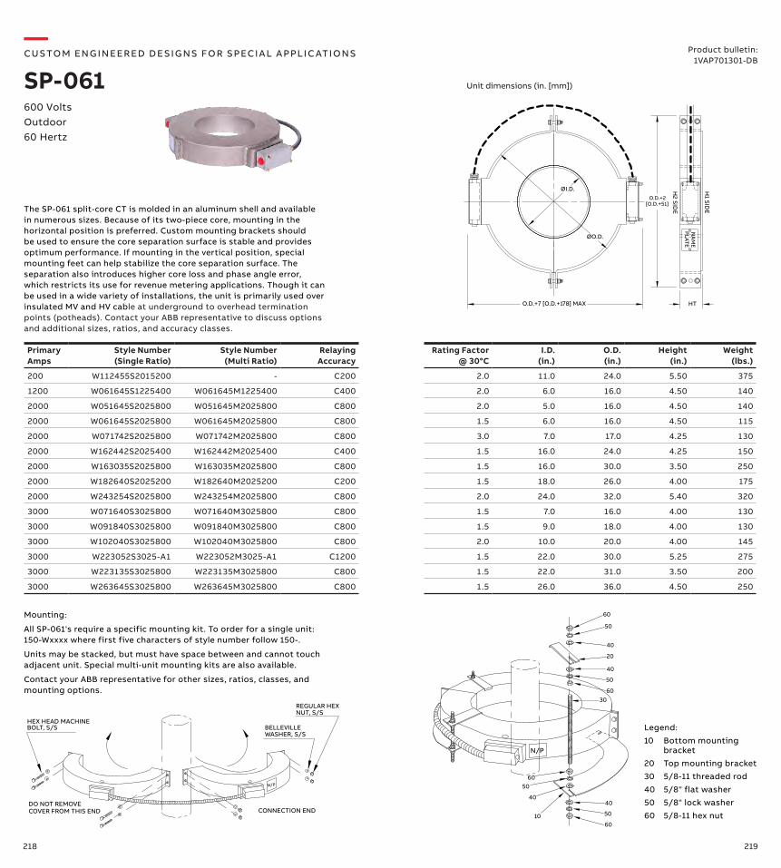
218 219
600 VoltsOutdoor60 Hertz
The SP-061 split-core CT is molded in an aluminum shell and available in numerous sizes. Because of its two-piece core, mounting in the horizontal position is preferred. Custom mounting brackets should be used to ensure the core separation surface is stable and provides optimum performance. If mounting in the vertical position, special mounting feet can help stabilize the core separation surface. The separation also introduces higher core loss and phase angle error, which restricts its use for revenue metering applications. Though it can be used in a wide variety of installations, the unit is primarily used over insulated MV and HV cable at underground to overhead termination points (potheads). Contact your ABB representative to discuss options and additional sizes, ratios, and accuracy classes.
Product bulletin:1VAP701301-DB
—CUS TO M ENG I N EER ED DE S I G NS FO R S PECI A L A PPLI C ATI O NS
SP-061
Primary Amps
Style Number (Single Ratio)
Style Number (Multi Ratio)
Relaying Accuracy
Rating Factor @ 30°C
I.D. (in.)
O.D. (in.)
Height (in.)
Weight (lbs.)
200 W112455S2015200 - C200 2.0 11.0 24.0 5.50 375
1200 W061645S1225400 W061645M1225400 C400 2.0 6.0 16.0 4.50 140
2000 W051645S2025800 W051645M2025800 C800 2.0 5.0 16.0 4.50 140
2000 W061645S2025800 W061645M2025800 C800 1.5 6.0 16.0 4.50 115
2000 W071742S2025800 W071742M2025800 C800 3.0 7.0 17.0 4.25 130
2000 W162442S2025400 W162442M2025400 C400 1.5 16.0 24.0 4.25 150
2000 W163035S2025800 W163035M2025800 C800 1.5 16.0 30.0 3.50 250
2000 W182640S2025200 W182640M2025200 C200 1.5 18.0 26.0 4.00 175
2000 W243254S2025800 W243254M2025800 C800 2.0 24.0 32.0 5.40 320
3000 W071640S3025800 W071640M3025800 C800 1.5 7.0 16.0 4.00 130
3000 W091840S3025800 W091840M3025800 C800 1.5 9.0 18.0 4.00 130
3000 W102040S3025800 W102040M3025800 C800 2.0 10.0 20.0 4.00 145
3000 W223052S3025-A1 W223052M3025-A1 C1200 1.5 22.0 30.0 5.25 275
3000 W223135S3025800 W223135M3025800 C800 1.5 22.0 31.0 3.50 200
3000 W263645S3025800 W263645M3025800 C800 1.5 26.0 36.0 4.50 250
NA
ME
PLATE
O.D.+7 [O.D.+178] MAX
O.D.+2[O.D.+51]
HT
ØO.D.
ØI.D. H1 SID
E
H2 SID
E
Unit dimensions (in. [mm])
N/P
60
50
40
6050
40
10
3060
50
40
60
20
40
50
Mounting:
All SP-061's require a specific mounting kit. To order for a single unit: 150-Wxxxx where first five characters of style number follow 150-.
Units may be stacked, but must have space between and cannot touch adjacent unit. Special multi-unit mounting kits are also available.
Contact your ABB representative for other sizes, ratios, classes, and mounting options.
Legend:
10 Bottom mounting bracket
20 Top mounting bracket
30 5/8-11 threaded rod
40 5/8" flat washer
50 5/8" lock washer
60 5/8-11 hex nutCONNECTION END
DO NOT REMOVE
N/P
REGULAR HEX
BELLEVILLE
NUT, S/S
WASHER, S/S
HEX HEAD MACHINEBOLT, S/S
COVER FROM THIS END
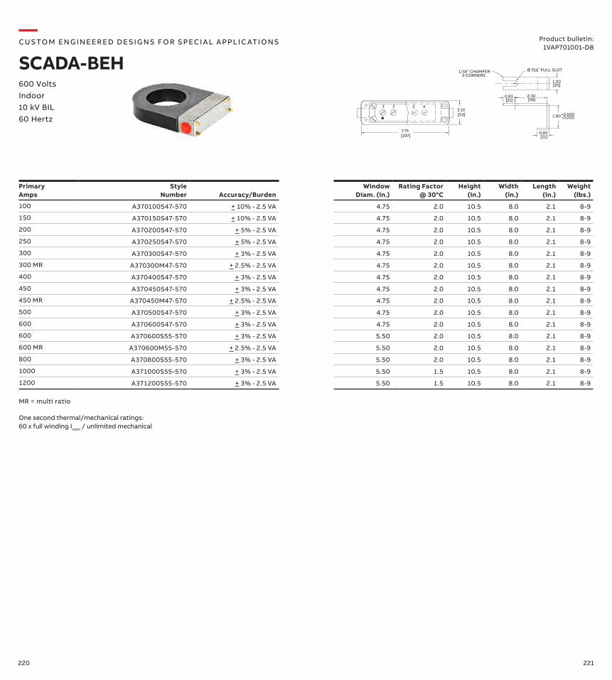
220 221
1 2 3 4
7.75[197]
2.10[53]
2.30[58]
0.83 [21]
0.83 [21]
1.80+0.005-0.000
Ø 7 16 " 1/16" CHAMFER2-CORNERS
1.00[25]
FULL SLOT
Primary Amps
Style Number Accuracy/Burden
Window Diam. (in.)
Rating Factor @ 30°C
Height (in.)
Width (in.)
Length (in.)
Weight (lbs.)
100 A370100S47-570 + 10% - 2.5 VA 4.75 2.0 10.5 8.0 2.1 8-9
150 A370150S47-570 + 10% - 2.5 VA 4.75 2.0 10.5 8.0 2.1 8-9
200 A370200S47-570 + 5% - 2.5 VA 4.75 2.0 10.5 8.0 2.1 8-9
250 A370250S47-570 + 5% - 2.5 VA 4.75 2.0 10.5 8.0 2.1 8-9
300 A370300S47-570 + 3% - 2.5 VA 4.75 2.0 10.5 8.0 2.1 8-9
300 MR A370300M47-570 + 2.5% - 2.5 VA 4.75 2.0 10.5 8.0 2.1 8-9
400 A370400S47-570 + 3% - 2.5 VA 4.75 2.0 10.5 8.0 2.1 8-9
450 A370450S47-570 + 3% - 2.5 VA 4.75 2.0 10.5 8.0 2.1 8-9
450 MR A370450M47-570 + 2.5% - 2.5 VA 4.75 2.0 10.5 8.0 2.1 8-9
500 A370500S47-570 + 3% - 2.5 VA 4.75 2.0 10.5 8.0 2.1 8-9
600 A370600S47-570 + 3% - 2.5 VA 4.75 2.0 10.5 8.0 2.1 8-9
600 A370600S55-570 + 3% - 2.5 VA 5.50 2.0 10.5 8.0 2.1 8-9
600 MR A370600M55-570 + 2.5% - 2.5 VA 5.50 2.0 10.5 8.0 2.1 8-9
800 A370800S55-570 + 3% - 2.5 VA 5.50 2.0 10.5 8.0 2.1 8-9
1000 A371000S55-570 + 3% - 2.5 VA 5.50 1.5 10.5 8.0 2.1 8-9
1200 A371200S55-570 + 3% - 2.5 VA 5.50 1.5 10.5 8.0 2.1 8-9
MR = multi ratio
—CUS TO M ENG I N EER ED DE S I G NS FO R S PECI A L A PPLI C ATI O NS
SCADA-BEH600 Volts Indoor 10 kV BIL60 Hertz
Product bulletin:1VAP701001-DB
One second thermal/mechanical ratings: 60 x full winding Inom / unlimited mechanical
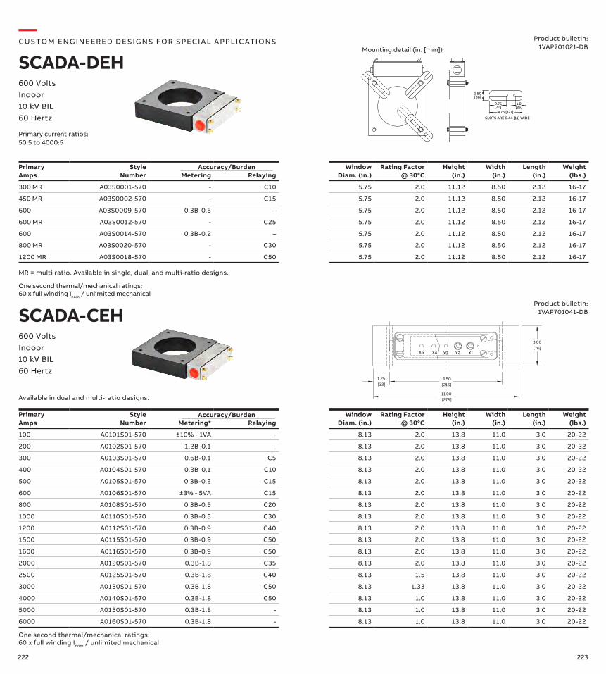
222 223
Primary Amps
Style Number Metering Relaying
Window Diam. (in.)
Rating Factor @ 30°C
Height (in.)
Width (in.)
Length (in.)
Weight (lbs.)
300 MR A03S0001-570 - C10 5.75 2.0 11.12 8.50 2.12 16-17
450 MR A03S0002-570 - C15 5.75 2.0 11.12 8.50 2.12 16-17
600 A03S0009-570 0.3B-0.5 – 5.75 2.0 11.12 8.50 2.12 16-17
600 MR A03S0012-570 - C25 5.75 2.0 11.12 8.50 2.12 16-17
600 A03S0014-570 0.3B-0.2 – 5.75 2.0 11.12 8.50 2.12 16-17
800 MR A03S0020-570 - C30 5.75 2.0 11.12 8.50 2.12 16-17
1200 MR A03S0018-570 - C50 5.75 2.0 11.12 8.50 2.12 16-17
MR = multi ratio. Available in single, dual, and multi-ratio designs.
Accuracy/Burden
One second thermal/mechanical ratings: 60 x full winding Inom / unlimited mechanical
—CUS TO M ENG I N EER ED DE S I G NS FO R S PECI A L A PPLI C ATI O NS
SCADA-DEH600 Volts Indoor 10 kV BIL60 Hertz
Product bulletin:1VAP701021-DB
Primary current ratios:50:5 to 4000:5
4.75 [121]
2.75 1.0
1.50[38]
[70] [25]
SLOTS ARE 0.44 [11] WIDE
Mounting detail (in. [mm])
8.50[216]
11.00[279]
X1X2X3X5 X4
3.00
[32]
[76]
1.25
Primary Amps
Style Number Metering* Relaying
WindowDiam. (in.)
Rating Factor @ 30°C
Height (in.)
Width (in.)
Length (in.)
Weight (lbs.)
100 A0101S01-570 ±10% - 1VA - 8.13 2.0 13.8 11.0 3.0 20-22
200 A0102S01-570 1.2B-0.1 - 8.13 2.0 13.8 11.0 3.0 20-22
300 A0103S01-570 0.6B-0.1 C5 8.13 2.0 13.8 11.0 3.0 20-22
400 A0104S01-570 0.3B-0.1 C10 8.13 2.0 13.8 11.0 3.0 20-22
500 A0105S01-570 0.3B-0.2 C15 8.13 2.0 13.8 11.0 3.0 20-22
600 A0106S01-570 ±3% - 5VA C15 8.13 2.0 13.8 11.0 3.0 20-22
800 A0108S01-570 0.3B-0.5 C20 8.13 2.0 13.8 11.0 3.0 20-22
1000 A0110S01-570 0.3B-0.5 C30 8.13 2.0 13.8 11.0 3.0 20-22
1200 A0112S01-570 0.3B-0.9 C40 8.13 2.0 13.8 11.0 3.0 20-22
1500 A0115S01-570 0.3B-0.9 C50 8.13 2.0 13.8 11.0 3.0 20-22
1600 A0116S01-570 0.3B-0.9 C50 8.13 2.0 13.8 11.0 3.0 20-22
2000 A0120S01-570 0.3B-1.8 C35 8.13 2.0 13.8 11.0 3.0 20-22
2500 A0125S01-570 0.3B-1.8 C40 8.13 1.5 13.8 11.0 3.0 20-22
3000 A0130S01-570 0.3B-1.8 C50 8.13 1.33 13.8 11.0 3.0 20-22
4000 A0140S01-570 0.3B-1.8 C50 8.13 1.0 13.8 11.0 3.0 20-22
5000 A0150S01-570 0.3B-1.8 - 8.13 1.0 13.8 11.0 3.0 20-22
6000 A0160S01-570 0.3B-1.8 - 8.13 1.0 13.8 11.0 3.0 20-22
Available in dual and multi-ratio designs.
One second thermal/mechanical ratings: 60 x full winding Inom / unlimited mechanical
SCADA-CEH600 Volts Indoor 10 kV BIL60 Hertz
Product bulletin:1VAP701041-DB
Accuracy/Burden
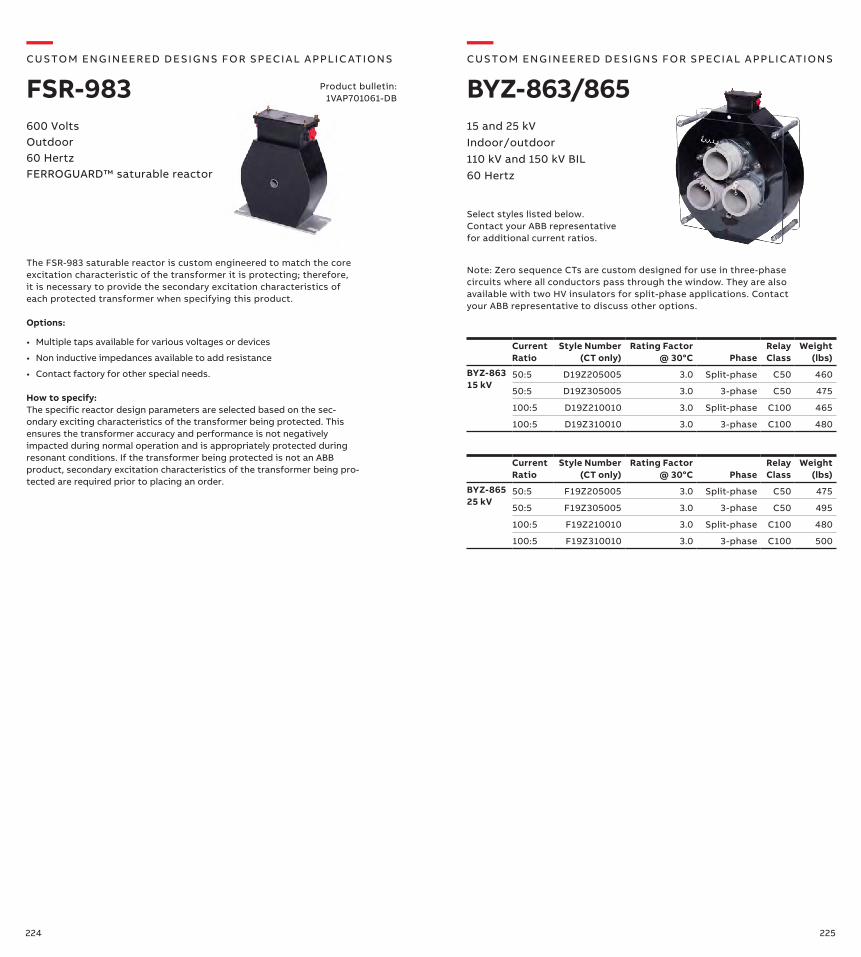
224 225
Product bulletin:1VAP701061-DB
The FSR-983 saturable reactor is custom engineered to match the core excitation characteristic of the transformer it is protecting; therefore, it is necessary to provide the secondary excitation characteristics of each protected transformer when specifying this product.
Options:
• Multiple taps available for various voltages or devices
• Non inductive impedances available to add resistance
• Contact factory for other special needs.
How to specify:The specific reactor design parameters are selected based on the sec-ondary exciting characteristics of the transformer being protected. This ensures the transformer accuracy and performance is not negatively impacted during normal operation and is appropriately protected during resonant conditions. If the transformer being protected is not an ABB product, secondary excitation characteristics of the transformer being pro-tected are required prior to placing an order.
600 VoltsOutdoor60 HertzFERROGUARD™ saturable reactor
Note: Zero sequence CTs are custom designed for use in three-phase circuits where all conductors pass through the window. They are also available with two HV insulators for split-phase applications. Contact your ABB representative to discuss other options.
—CUS TO M ENG I N EER ED DE S I G NS FO R S PECI A L A PPLI C ATI O NS
BYZ-863/86515 and 25 kV Indoor/outdoor 110 kV and 150 kV BIL60 Hertz
Current Ratio
Style Number (CT only)
Rating Factor @ 30°C Phase
Relay Class
Weight (lbs)
BYZ-863 15 kV
50:5 D19Z205005 3.0 Split-phase C50 460
50:5 D19Z305005 3.0 3-phase C50 475
100:5 D19Z210010 3.0 Split-phase C100 465
100:5 D19Z310010 3.0 3-phase C100 480
Current Ratio
Style Number (CT only)
Rating Factor @ 30°C Phase
Relay Class
Weight (lbs)
BYZ-865 25 kV
50:5 F19Z205005 3.0 Split-phase C50 475
50:5 F19Z305005 3.0 3-phase C50 495
100:5 F19Z210010 3.0 Split-phase C100 480
100:5 F19Z310010 3.0 3-phase C100 500
Select styles listed below. Contact your ABB representative for additional current ratios.
—CUS TO M ENG I N EER ED DE S I G NS FO R S PECI A L A PPLI C ATI O NS
FSR-983
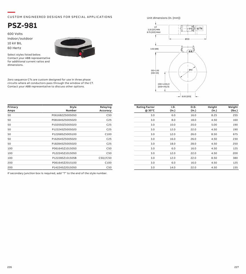
226 227
600 VoltsIndoor/outdoor 10 kV BIL60 Hertz
Zero sequence CTs are custom designed for use in three phase circuits where all conductors pass through the window of the CT. Contact your ABB representative to discuss other options.
—CUS TO M ENG I N EER ED DE S I G NS FO R S PECI A L A PPLI C ATI O NS
PSZ-981
Primary Amps
Style Number
Relaying Accuracy
Rating Factor @ 30°C
I.D. (in.)
O.D. (in.)
Height (in.)
Weight (lbs.)
50 P061682Z5005050 C50 3.0 6.0 16.0 8.25 255
50 P081845Z5005020 C25 3.0 8.0 18.0 4.50 160
50 P102050Z5005020 C25 3.0 10.0 20.0 5.00 190
50 P122245Z5005020 C25 3.0 12.0 22.0 4.50 190
50 P122685Z5005100 C100 3.0 12.0 26.0 8.50 675
50 P162645Z5005020 C25 3.0 16.0 26.0 4.50 230
50 P182845Z5005020 C25 3.0 18.0 28.0 4.50 250
100 P061645Z1015050 C50 3.0 6.0 16.0 4.50 125
100 P122245Z1015050 C50 3.0 12.0 22.0 4.50 200
100 P122285Z101505B C50//C50 3.0 12.0 22.0 8.50 380
200 P061645Z2015100 C100 3.0 6.0 16.0 4.50 125
200 P142245Z2015050 C50 3.0 14.0 22.0 4.50 155
Select styles listed below. Contact your ABB representative for additional current ratios and dimensions.
X3 X1X2
N/P
ØOD
8.00 [203]
HT2.25 [57] MIN
8.75 [222] MAX
3.50 [89]
OD+1.00[OD+25]
(OD+1.00)/2[(OD+25)/2]
ØID
If secondary junction box is required, add “T” to the end of the style number.
Unit dimensions (in. [mm])
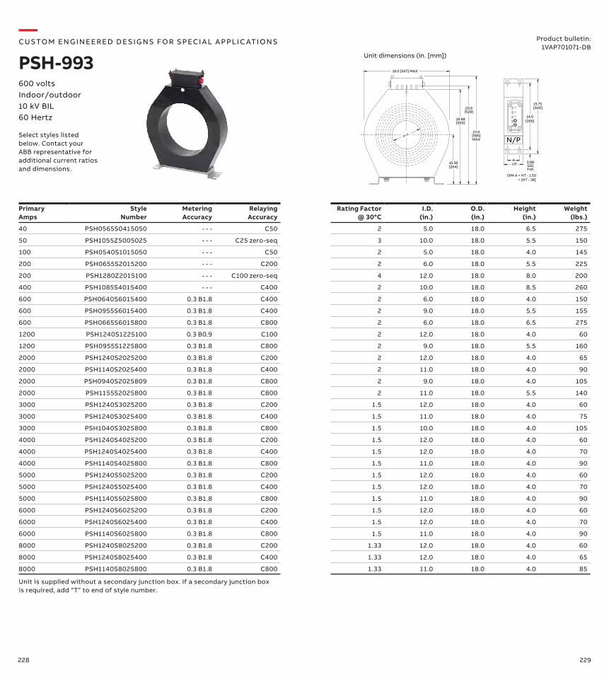
228 229
—CUS TO M ENG I N EER ED DE S I G NS FO R S PECI A L A PPLI C ATI O NS
PSH-993600 voltsIndoor/outdoor10 kV BIL60 Hertz
Product bulletin:1VAP701071-DB
Primary Amps
Style Number
MeteringAccuracy
Relaying Accuracy
Rating Factor @ 30°C
I.D. (in.)
O.D. (in.)
Height (in.)
Weight (lbs.)
40 PSH0565S0415050 - - - C50 2 5.0 18.0 6.5 275
50 PSH1055Z5005025 - - - C25 zero-seq 3 10.0 18.0 5.5 150
100 PSH0540S1015050 - - - C50 2 5.0 18.0 4.0 145
200 PSH0655S2015200 - - - C200 2 6.0 18.0 5.5 225
200 PSH1280Z2015100 - - - C100 zero-seq 4 12.0 18.0 8.0 200
400 PSH1085S4015400 - - - C400 2 10.0 18.0 8.5 260
600 PSH0640S6015400 0.3 B1.8 C400 2 6.0 18.0 4.0 150
600 PSH0955S6015400 0.3 B1.8 C400 2 9.0 18.0 5.5 155
600 PSH0665S6015800 0.3 B1.8 C800 2 6.0 18.0 6.5 275
1200 PSH1240S1225100 0.3 B0.9 C100 2 12.0 18.0 4.0 60
1200 PSH0955S1225800 0.3 B1.8 C800 2 9.0 18.0 5.5 160
2000 PSH1240S2025200 0.3 B1.8 C200 2 12.0 18.0 4.0 65
2000 PSH1140S2025400 0.3 B1.8 C400 2 11.0 18.0 4.0 90
2000 PSH0940S2025809 0.3 B1.8 C800 2 9.0 18.0 4.0 105
2000 PSH1155S2025800 0.3 B1.8 C800 2 11.0 18.0 5.5 140
3000 PSH1240S3025200 0.3 B1.8 C200 1.5 12.0 18.0 4.0 60
3000 PSH1240S3025400 0.3 B1.8 C400 1.5 11.0 18.0 4.0 75
3000 PSH1040S3025800 0.3 B1.8 C800 1.5 10.0 18.0 4.0 105
4000 PSH1240S4025200 0.3 B1.8 C200 1.5 12.0 18.0 4.0 60
4000 PSH1240S4025400 0.3 B1.8 C400 1.5 12.0 18.0 4.0 70
4000 PSH1140S4025800 0.3 B1.8 C800 1.5 11.0 18.0 4.0 90
5000 PSH1240S5025200 0.3 B1.8 C200 1.5 12.0 18.0 4.0 60
5000 PSH1240S5025400 0.3 B1.8 C400 1.5 12.0 18.0 4.0 70
5000 PSH1140S5025800 0.3 B1.8 C800 1.5 11.0 18.0 4.0 90
6000 PSH1240S6025200 0.3 B1.8 C200 1.5 12.0 18.0 4.0 60
6000 PSH1240S6025400 0.3 B1.8 C400 1.5 12.0 18.0 4.0 70
6000 PSH1140S6025800 0.3 B1.8 C800 1.5 11.0 18.0 4.0 90
8000 PSH1240S8025200 0.3 B1.8 C200 1.33 12.0 18.0 4.0 60
8000 PSH1240S8025400 0.3 B1.8 C400 1.33 12.0 18.0 4.0 65
8000 PSH1140S8025800 0.3 B1.8 C800 1.33 11.0 18.0 4.0 85
10.38
19.88
Ø I.D.
[505]
[264]
23.0[585]
18.0 [457] MAX
MAX
[528]20.8
14.0
[400]
0.88HTA
[22]TYP.
15.75
[356]
DIM A = HT - 1.50= [HT - 38]
X4
X5
X1
X3
X2
N/PSelect styles listed below. Contact your ABB representative for additional current ratios and dimensions.
Unit dimensions (in. [mm])
Unit is supplied without a secondary junction box. If a secondary junction box is required, add “T” to end of style number.
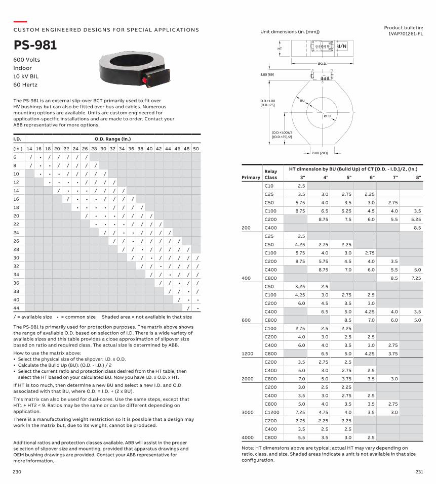
230 231
600 Volts Indoor 10 kV BIL60 Hertz
Product bulletin:1VAP701261-FL
—CUS TO M ENG I N EER ED DE S I G NS FO R S PECI A L A PPLI C ATI O NS
PS-981
The PS-981 is an external slip-over BCT primarily used to fit over HV bushings but can also be fitted over bus and cables. Numerous mounting options are available. Units are custom engineered for application-specific installations and are made to order. Contact your ABB representative for more options.
X3 X1X2X5 X4
N/P
ØO.D.
8.00 [203]
HT
3.50 [89]
O.D.+1.00[O.D.+25]
(O.D.+1.00)/2[(O.D.+25)/2]
ØI.D.
BU
I.D. O.D. Range (in.)
(in.) 14 16 18 20 22 24 26 28 30 32 34 36 38 40 42 44 46 48 50
6 / • / / / / /
8 / • • / / / / /
10 • • • / / / / /
12 • • • • / / / /
14 / • • • / / / /
16 / • • • / / / /
18 • • • • / / / /
20 / • • • / / / /
22 • • • • / / / /
24 / / • • / / / /
26 / / • / / / / /
28 / / • / / / / /
30 / / • / / / / /
32 / / • / / / /
34 / / • / / /
36 / / • / /
38 / / • /
40 / • •
44 / •
/ = available size • = common size Shaded area = not available in that size
The PS-981 is primarily used for protection purposes. The matrix above shows the range of available O.D. based on selection of I.D. There is a wide variety of available sizes and this table provides a close approximation of slipover size based on ratio and required class. The actual size is determined by ABB.
How to use the matrix above:• Select the physical size of the slipover: I.D. x O.D.• Calculate the Build Up (BU): (O.D. - I.D.) / 2• Select the current ratio and protection class desired from the HT table, then
select the HT based on your calculated BU. Now you have I.D. x O.D. x HT.
If HT is too much, then determine a new BU and select a new I.D. and O.D. associated with that BU, where O.D. = I.D. + (2 x BU).
This matrix can also be used for dual-cores. Use the same steps, except that HT1 + HT2 < 9. Ratios may be the same or can be different depending on application.
There is a manufacturing weight restriction so it is possible that a design may work in the matrix but, due to its weight, cannot be produced.
Relay Class
HT dimension by BU (Build Up) of CT [O.D. - I.D.]/2, (in.)
Primary 3" 4" 5" 6" 7" 8"
200
C10 2.5
C25 3.5 3.0 2.75 2.25
C50 5.75 4.0 3.5 3.0 2.75
C100 8.75 6.5 5.25 4.5 4.0 3.5
C200 8.75 7.5 6.0 5.5 5.25
C400 8.5
400
C25 2.5
C50 4.25 2.75 2.25
C100 5.75 4.0 3.0 2.75
C200 8.75 5.75 4.5 4.0 3.5
C400 8.75 7.0 6.0 5.5 5.0
C800 8.5 7.25
600
C50 3.25 2.5
C100 4.25 3.0 2.75 2.5
C200 6.0 4.5 3.5 3.0
C400 6.5 5.0 4.25 4.0 3.5
C800 8.5 7.0 6.0 5.0
1200
C100 2.75 2.5 2.25
C200 4.0 3.0 2.5 2.5
C400 6.0 4.0 3.5 3.0 2.75
C800 6.5 5.0 4.25 3.75
2000
C200 3.5 2.75 2.5
C400 5.0 3.0 2.75 2.5
C800 7.0 5.0 3.75 3.5 3.0
3000
C200 3.0 2.5 2.25
C400 3.5 3.0 2.75 2.5
C800 5.0 4.0 3.5 3.5 2.75
C1200 7.25 4.75 4.0 3.5 3.0
4000
C200 2.75 2.25 2.25
C400 3.5 2.5 2.5
C800 5.5 3.5 3.0 2.5Additional ratios and protection classes available. ABB will assist in the proper selection of slipover size and mounting, provided that apparatus drawings and OEM bushing drawings are provided. Contact your ABB representative for more information.
Note: HT dimensions above are typical; actual HT may vary depending on ratio, class, and size. Shaded areas indicate a unit is not available in that size configuration.
Unit dimensions (in. [mm])
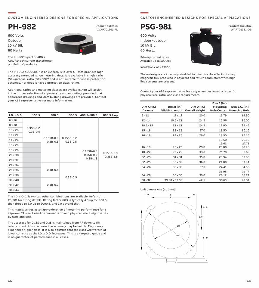
232 233
600 VoltsOutdoor10 kV BIL60 Hertz
—CUS TO M ENG I N EER ED DE S I G NS FO R S PECI A L A PPLI C ATI O NS
PH-982
The PH-982 ACCUSlipTM is an external slip-over CT that provides high accuracy extended range metering duty. It is available in single ratio (SR) and dual ratio (DR) ONLY and is not suitable for use in protection schemes, nor does it have a protection class rating.
Additional ratios and metering classes are available. ABB will assist in the proper selection of slipover size and mounting, provided that apparatus drawings and OEM bushing drawings are provided. Contact your ABB representative for more information.
The PH-982 is part of ABB’s AccuRange® current transformer portfolio of products.
I.D. x O.D. 150:5 200:5 300:5 400:5-600:5 800:5 & up
6 x 16
0.3SB-0.2 0.3B-0.5
0.15SB-0.2 0.3B-0.5
0.15SB-0.2 0.3B-0.5
0.15SB-0.50.3SB-0.9
0.3B-1.8
0.15SB-0.90.3SB-1.8
8 x 18
10 x 20
12 x 22
14 x 24
16 x 26
18 x 28
20 x 30
22 x 32
24 x 34
0.3B-0.5
0.3B-0.5
26 x 36
28 x 38
30 x 40
0.3B-0.232 x 42
34 x 44
The I.D. x O.D. is typical; other combinations are available. Refer to PS-981 for sizing details. Rating factor (RF) is typically 4.0 up to 1200:5, then drops to 3.0 up to 2000:5, and 2.0 beyond that.
This matrix serves as an approximation of metering performance for a slip-over CT size, based on current ratio and physical size. Height varies by ratio and size.
The accuracy for 0.15S and 0.3S is maintained from RF down to 5% rated current. In some cases the accuracy may be held to 1%, or may experience higher class. It is also possible that the class will worsen at lower currents as the I.D. x O.D. increases. This is a targeted guide and is no guarantee of performance in all cases.
—CUS TO M ENG I N EER ED DE S I G NS FO R S PECI A L A PPLI C ATI O NS
PSG-981600 Volts Indoor/outdoor10 kV BIL60 Hertz
Product bulletin:1VAP701331-DB
Primary current ratios:Available up to 50000:5
Dim A (in.)ID range
Dim B (in.)Width x Length
Dim D (in.)Overall Height
Dim E (in.)Mounting
Hole CenterDim B.C. (in.)
Mounting Hole
9 - 12 17 x 17 20.0 13.79 19.50
12 - 14 19.5 x 21 24.5 15.56 22.00
10.5 - 15 21 x 21 24.5 18.00 25.46
15 - 18 23 x 23 27.0 18.50 26.16
16 - 18 24 x 25 29.0 18.50 26.16
16 - 18 25 x 25 29.0
18.50 19.62 20.00
26.16 27.75 28.28
18 - 22 29 x 29 33.0 21.70 30.69
22 - 25 31 x 31 35.0 23.94 33.86
22 - 25 32 x 32 36.0 24.00 33.94
24 - 26 33 x 33 37.0 24.41 34.52
24 - 28 35 x 35 39.025.98 28.12
36.74 39.77
28 - 32 39.38 x 39.38 42.5 30.63 43.31
ØA
ØB.C.
E
B/2
D
EB
B
Contact your ABB representative for a style number based on specific physical size, ratio, and class requirements.
These designs are internally shielded to minimize the effects of stray magnetic flux produced in adjacent and return conductors when high line currents are present.
Insulation class: 130° C
Unit dimensions (in. [mm])
Product bulletin:1VAP701261-FL
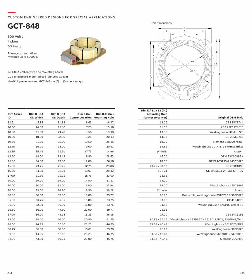
234 235
GCT-802: coil only with no mounting board
GCT-848: board-mounted coil (pictured above)
HW-945: pre-assembled GCT-848s in (2) to (5) stack arrays
600 Volts Indoor60 Hertz
Primary current ratios:Available up to 50000:5
Dim A (in.)ID
Dim B (in.)OD Width
Dim D (in.)OD Depth
Dim C (in.)Center Location
Dim B.C. (in.)Mounting Hole
Dim E / E1 x E2 (in.) Mounting Hole
(center to center) Original OEM Style
9.25 17.25 21.38 8.63 18.47 13.06 GE 235C3744
10.00 14.50 15.00 7.25 15.56 11.00 ABB 7526A78610
10.00 17.00 21.70 8.50 18.38 13.00 Westinghouse 30-A-8725
10.50 18.50 22.50 9.25 20.33 14.38 GE 235C3745
10.50 21.00 25.50 10.50 25.46 18.00 Siemens S2R2 Aeropak
12.75 19.00 24.00 9.60 20.63 14.58 Westinghouse 30-A-8724 w/mtg brkts
12.75 35.44 39.91 17.72 14.96 (4) in ID Alstom
13.50 19.00 23.13 9.50 22.63 16.00 OEM 23C6099BK
15.50 24.00 29.00 12.00 26.16 18.50 GE 224C5195 & 245C5625
15.50 24.75 29.75 12.75 29.88 21.75 x 20.50 GE 233C1093
16.00 24.00 28.03 13.03 28.32 19 x 21 GE 1925693-2, Type CTR-OY
17.00 31.50 36.75 15.75 33.69 23.82 -
20.00 29.00 29.00 14.50 31.11 22.00 -
20.00 30.00 32.00 15.00 33.94 24.00 Westinghouse 155C7695
20.00 39.00 38.80 19.50 36.22 Circular Round
20.50 36.00 39.50 18.00 39.77 28.12 Dual-coils, Westinghouse 891D782 & 383D623
25.00 31.75 35.25 15.88 33.75 23.86 GE 4194C73
26.00 32.00 36.00 16.00 33.75 23.88 Westinghouse 46A5195, offset TB
26.50 36.00 47.50 22.00 39.77 28.12 -
27.00 36.00 41.13 18.25 38.18 27.00 GE 224C5198
28.00 39.00 46.00 20.50 41.75 20.88 x 36.16 Westinghouse 383D567 / 5618D12/D71, 7316D43/D44
28.00 44.25 50.16 23.23 46.75 23.38 x 40.49 Westinghouse 5614D23/D24
28.75 36.00 38.00 18.81 39.78 28.13 Westinghouse 383D623
30.50 44.25 50.16 23.23 46.75 23.38 x 40.49 Westinghouse 5603D03 / 5609D13
32.00 43.00 50.25 22.00 46.75 23.38 x 40.49 Siemens 2269J99
ØA
N/P
ØB.C.
E
C
D
EB
E 1
E 2
—CUS TO M ENG I N EER ED DE S I G NS FO R S PECI A L A PPLI C ATI O NS
GCT-848 Unit dimensions
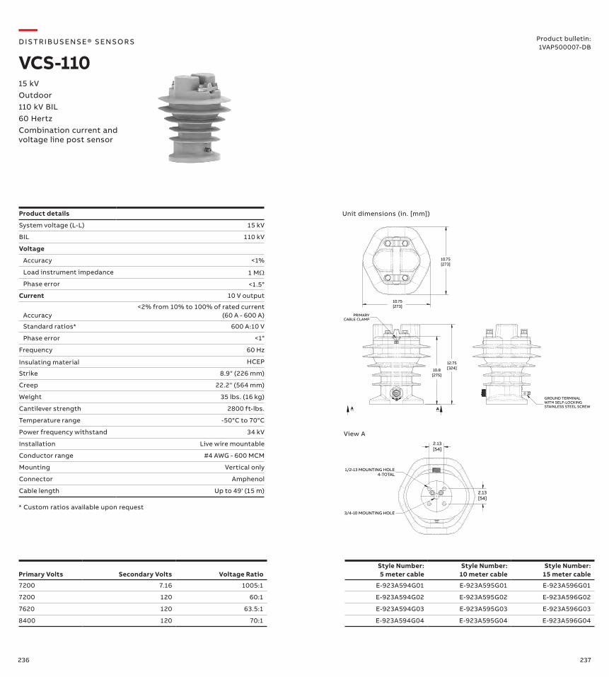
236 237
* Custom ratios available upon request
Unit dimensions (in. [mm])
A A
B
10.75[273]
10.75[273]
PRIMARYCABLE CLAMP
12.75[324]10.8
[275]
GROUND TERMINALWITH SELF-LOCKINGSTAINLESS STEEL SCREW
2.13[54]
2.13[54]
1/2-13 MOUNTING HOLE4-TOTAL
3/4-10 MOUNTING HOLE
View A
Primary Volts Secondary Volts Voltage RatioStyle Number: 5 meter cable
Style Number:10 meter cable
Style Number:15 meter cable
7200 7.16 1005:1 E-923A594G01 E-923A595G01 E-923A596G01
7200 120 60:1 E-923A594G02 E-923A595G02 E-923A596G02
7620 120 63.5:1 E-923A594G03 E-923A595G03 E-923A596G03
8400 120 70:1 E-923A594G04 E-923A595G04 E-923A596G04
—D IS TR I B US ENS E® S ENSO R S
VCS-110Product bulletin:1VAP500007-DB
15 kVOutdoor 110 kV BIL60 HertzCombination current and voltage line post sensor
Product details
System voltage (L-L) 15 kV
BIL 110 kV
Voltage
Accuracy <1%
Load instrument impedance 1 MΩ
Phase error <1.5°
Current 10 V output
Accuracy<2% from 10% to 100% of rated current
(60 A - 600 A)
Standard ratios* 600 A:10 V
Phase error <1°
Frequency 60 Hz
Insulating material HCEP
Strike 8.9" (226 mm)
Creep 22.2" (564 mm)
Weight 35 lbs. (16 kg)
Cantilever strength 2800 ft-lbs.
Temperature range -50°C to 70°C
Power frequency withstand 34 kV
Installation Live wire mountable
Conductor range #4 AWG - 600 MCM
Mounting Vertical only
Connector Amphenol
Cable length Up to 49' (15 m)
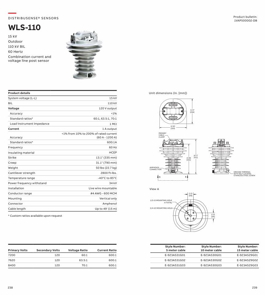
238 239
* Custom ratios available upon request
Unit dimensions (in. [mm])
AMPHENOLCONNECTION
PRIMARYCABLECLAMP
16.17[411]13.98
[355]
A A
12.60[320]
11.57[294]
GROUND TERMINALWITH SELF-LOCKING STAINLESS STEEL SCREW
4-TOTAL1/2-13 MOUNTING HOLE
3/4-10 MOUNTING HOLE
2.13[54]
2.13[54]
View A
Primary Volts Secondary Volts Voltage Ratio Current RatioStyle Number: 5 meter cable
Style Number:10 meter cable
Style Number:15 meter cable
7200 120 60:1 600:1 E-923A531G01 E-923A530G01 E-923A529G01
7620 120 63.5:1 600:1 E-923A531G02 E-923A530G02 E-923A529G02
8400 120 70:1 600:1 E-923A531G03 E-923A530G03 E-923A529G03
—D IS TR I B US ENS E® S ENSO R S
WLS-11015 kVOutdoor 110 kV BIL60 HertzCombination current and voltage line post sensor
Product bulletin:1VAP500002-DB
Product details
System voltage (L-L) 15 kV
BIL 110 kV
Voltage 120 V output
Accuracy <1%
Standard ratios* 60:1, 63.5:1, 70:1
Load instrument impedance 1 MΩ
Current 1 A output
Accuracy<1% from 10% to 200% of rated current
(60 A - 1200 A)
Standard ratios* 600:1A
Frequency 60 Hz
Insulating material HCEP
Strike 13.1" (335 mm)
Creep 31.1" (790 mm)
Weight 50 lbs (22.7 kg)
Cantilever strength 2800 ft-lbs.
Temperature range -40°C to 85°C
Power frequency withstand 34 kV
Installation Live wire mountable
Conductor range #4 AWG - 600 MCM
Mounting Vertical only
Connector Amphenol
Cable length Up to 49' (15 m)

240 241
Characteristic Value
System voltage (L-L) 15 kV (IEC: 17.5 kV)
BIL 110 kV
Load instrument impedance 1 MΩ
Current 10 V output
Accuracy<2% from 10% to 100%
of rated current (60 A - 600 A)
Standard ratios* 600 A:10 V
Frequency 60 Hz (IEC: 50 Hz)
Insulating material HCEP
Strike 8" (203 mm)
Creep 20.25" (514 mm)
Weight 33 lbs. (15 kg)
Cantilever strength 2800 ft-lbs.
Temperature range -50°C to 70°C
Power frequency withstand 34 kV
Installation Live wire mountable
Conductor range #4 AWG - 600 MCM
Mounting Vertical only
Connector Amphenol
Cable length Up to 49' (15 m)
* Custom ratios available upon request
Unit dimensions (in. [mm])
A A
B
10.75[273]
10.75[273]
PRIMARYCABLE CLAMP
12.75[324]10.8
[275]
GROUND TERMINALWITH SELF-LOCKINGSTAINLESS STEEL SCREW
2.13[54]
2.13[54]
1/2-13 MOUNTING HOLE4-TOTAL
3/4-10 MOUNTING HOLE
View A
—D IS TR I B US ENS E® S ENSO R S
VKS-11015 kVOutdoor 110 kV BIL60 HertzCurrent line post sensor
Product bulletin:1VAP500008-DB
Current RatioStyle Number: 5 meter cable
Style Number:10 meter cable
Style Number:15 meter cable
600:1 E-923A571G01 E-923A572G01 E-923A573G01
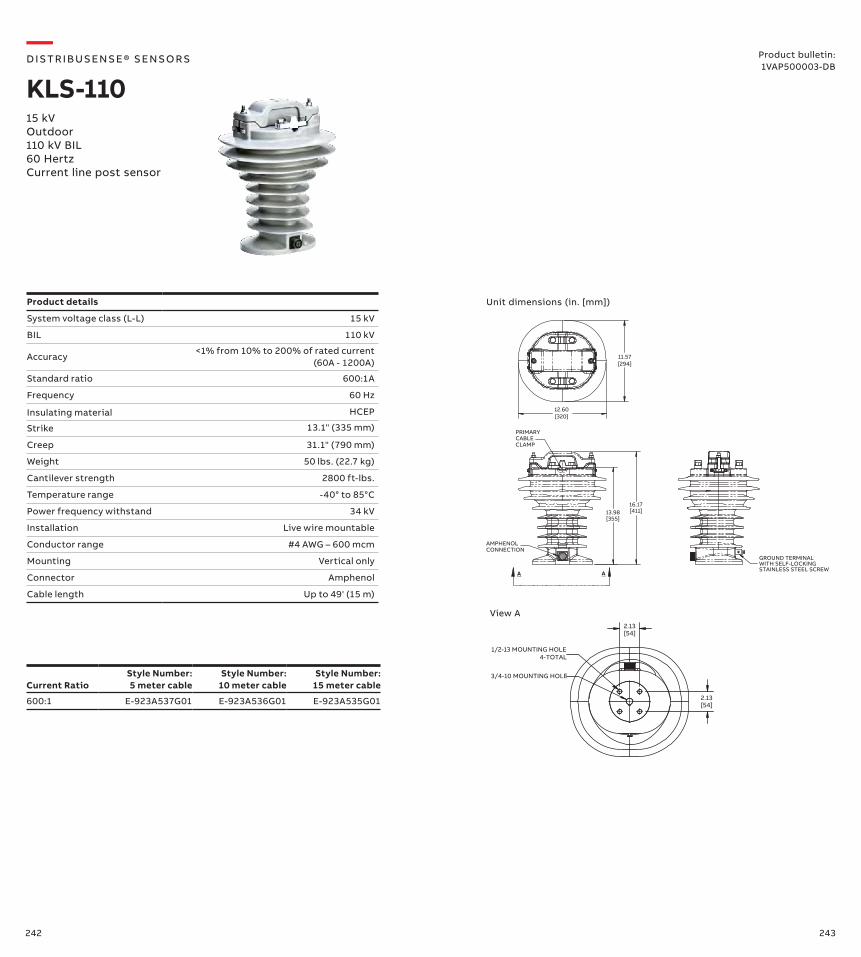
242 243
Unit dimensions (in. [mm])
AMPHENOLCONNECTION
PRIMARYCABLECLAMP
16.17[411]13.98
[355]
A A
12.60[320]
11.57[294]
GROUND TERMINALWITH SELF-LOCKING STAINLESS STEEL SCREW
4-TOTAL1/2-13 MOUNTING HOLE
3/4-10 MOUNTING HOLE
2.13[54]
2.13[54]
View A
—D IS TR I B US ENS E® S ENSO R S
KLS-11015 kVOutdoor 110 kV BIL60 HertzCurrent line post sensor
Product bulletin:1VAP500003-DB
Current RatioStyle Number: 5 meter cable
Style Number:10 meter cable
Style Number:15 meter cable
600:1 E-923A537G01 E-923A536G01 E-923A535G01
Product details
System voltage class (L-L) 15 kV
BIL 110 kV
Accuracy<1% from 10% to 200% of rated current
(60A - 1200A)
Standard ratio 600:1A
Frequency 60 Hz
Insulating material HCEP
Strike 13.1" (335 mm)
Creep 31.1" (790 mm)
Weight 50 lbs. (22.7 kg)
Cantilever strength 2800 ft-lbs.
Temperature range -40° to 85°C
Power frequency withstand 34 kV
Installation Live wire mountable
Conductor range #4 AWG – 600 mcm
Mounting Vertical only
Connector Amphenol
Cable length Up to 49' (15 m)
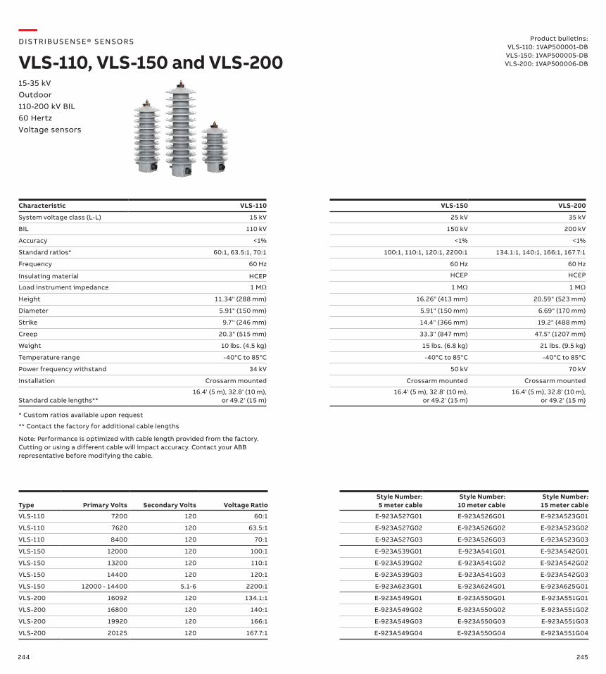
244 245
Characteristic VLS-110 VLS-150 VLS-200
System voltage class (L-L) 15 kV 25 kV 35 kV
BIL 110 kV 150 kV 200 kV
Accuracy <1% <1% <1%
Standard ratios* 60:1, 63.5:1, 70:1 100:1, 110:1, 120:1, 2200:1 134.1:1, 140:1, 166:1, 167.7:1
Frequency 60 Hz 60 Hz 60 Hz
Insulating material HCEP HCEP HCEP
Load instrument impedance 1 MΩ 1 MΩ 1 MΩ
Height 11.34" (288 mm) 16.26" (413 mm) 20.59" (523 mm)
Diameter 5.91" (150 mm) 5.91" (150 mm) 6.69" (170 mm)
Strike 9.7" (246 mm) 14.4" (366 mm) 19.2" (488 mm)
Creep 20.3" (515 mm) 33.3" (847 mm) 47.5" (1207 mm)
Weight 10 lbs. (4.5 kg) 15 lbs. (6.8 kg) 21 lbs. (9.5 kg)
Temperature range -40°C to 85°C -40°C to 85°C -40°C to 85°C
Power frequency withstand 34 kV 50 kV 70 kV
Installation Crossarm mounted Crossarm mounted Crossarm mounted
Standard cable lengths**16.4' (5 m), 32.8' (10 m),
or 49.2' (15 m)16.4' (5 m), 32.8' (10 m),
or 49.2' (15 m)16.4' (5 m), 32.8' (10 m),
or 49.2' (15 m)
** Contact the factory for additional cable lengths
Note: Performance is optimized with cable length provided from the factory. Cutting or using a different cable will impact accuracy. Contact your ABB representative before modifying the cable.
* Custom ratios available upon request
Type Primary Volts Secondary Volts Voltage RatioStyle Number: 5 meter cable
Style Number:10 meter cable
Style Number:15 meter cable
VLS-110 7200 120 60:1 E-923A527G01 E-923A526G01 E-923A523G01
VLS-110 7620 120 63.5:1 E-923A527G02 E-923A526G02 E-923A523G02
VLS-110 8400 120 70:1 E-923A527G03 E-923A526G03 E-923A523G03
VLS-150 12000 120 100:1 E-923A539G01 E-923A541G01 E-923A542G01
VLS-150 13200 120 110:1 E-923A539G02 E-923A541G02 E-923A542G02
VLS-150 14400 120 120:1 E-923A539G03 E-923A541G03 E-923A542G03
VLS-150 12000 - 14400 5.1-6 2200:1 E-923A623G01 E-923A624G01 E-923A625G01
VLS-200 16092 120 134.1:1 E-923A549G01 E-923A550G01 E-923A551G01
VLS-200 16800 120 140:1 E-923A549G02 E-923A550G02 E-923A551G02
VLS-200 19920 120 166:1 E-923A549G03 E-923A550G03 E-923A551G03
VLS-200 20125 120 167.7:1 E-923A549G04 E-923A550G04 E-923A551G04
—D IS TR I B US ENS E® S ENSO R S
VLS-110, VLS-150 and VLS-20015-35 kVOutdoor 110-200 kV BIL60 HertzVoltage sensors
Product bulletins:VLS-110: 1VAP500001-DB
VLS-150: 1VAP500005-DBVLS-200: 1VAP500006-DB
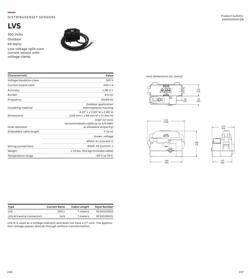
246 247
1.31[33]
.94[24]
.66[17]
4.25[108]
2.88[73]
3.66[93]
2.53[64]
2.22[56]
SOURCE
LOAD
LOAD
Unit dimensions (in. [mm])
Type Current Ratio Cable Length Style Number
LVS 200:1 7 meters 923A522G02
LVS-N (neutral connector) N/A 7 meters 923A538G01
Characteristic Value
Voltage insulation class 300 V
Current output ratio 200:1 A
Accuracy 1.2B-0.1
Burden B 0.1Ω
Frequency 50/60 Hz
Insulating materialOutdoor application
thermoplastic housing
Dimensions4.25" L x 2.60" W x 2.80" H
(108 mm L x 66 mm W x 71 mm H)
Inner diameter
0.68" (17 mm) (accommodates cable up to 4/0 AWG
at allowable ampacity)
Embedded cable length 7' (2 m)
Wiring connections
Green: voltage
White: X1 (current +)
Black: X2 (current -)
Weight 1.35 lbs. (0.6 kg) (includes cable)
Temperature range -50°C to 70°C
—D IS TR I B US ENS E® S ENSO R S
LVS300 VoltsOutdoor 60 HertzLow voltage split-core current sensor with voltage clamp
Product bulletin:1VAP500004-DB
LVS-N is used as a voltage indicator and does not have a CT core. The applica-tion voltage passes directly through without transformation.
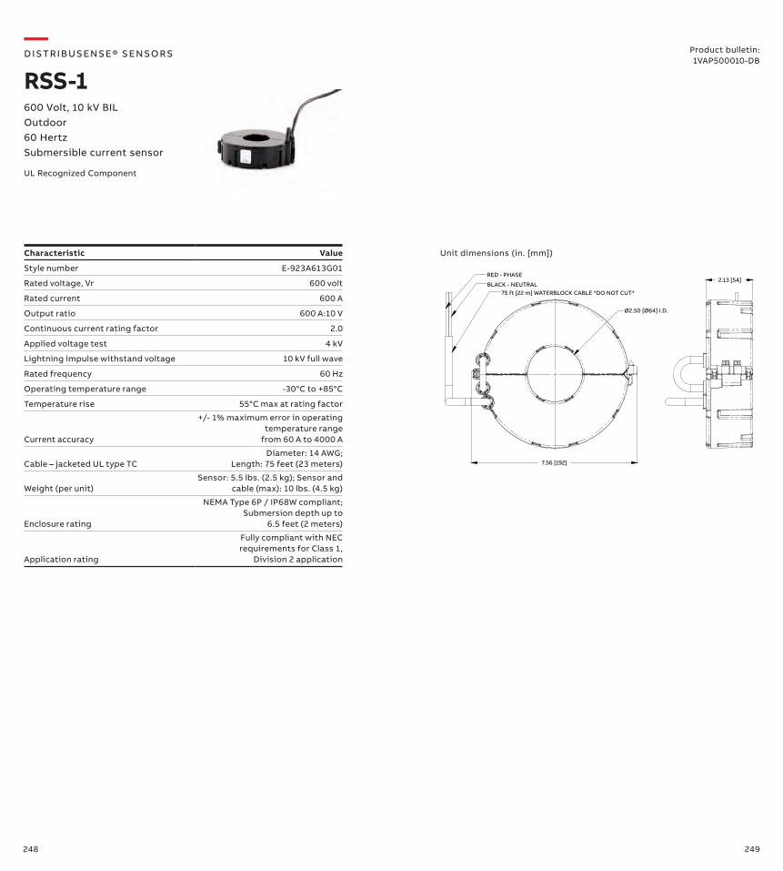
248 249
—D IS TR I B US ENS E® S ENSO R S
RSS-1
UL Recognized Component
Characteristic Value
Style number E-923A613G01
Rated voltage, Vr 600 volt
Rated current 600 A
Output ratio 600 A:10 V
Continuous current rating factor 2.0
Applied voltage test 4 kV
Lightning impulse withstand voltage 10 kV full wave
Rated frequency 60 Hz
Operating temperature range -30°C to +85°C
Temperature rise 55°C max at rating factor
Current accuracy
+/- 1% maximum error in operating temperature range
from 60 A to 4000 A
Cable – jacketed UL type TCDiameter: 14 AWG;
Length: 75 feet (23 meters)
Weight (per unit)Sensor: 5.5 lbs. (2.5 kg); Sensor and
cable (max): 10 lbs. (4.5 kg)
Enclosure rating
NEMA Type 6P / IP68W compliant; Submersion depth up to
6.5 feet (2 meters)
Application rating
Fully compliant with NEC requirements for Class 1,
Division 2 application
Unit dimensions (in. [mm])
Ø2.50 [Ø64] I.D.
7.56 [192]
75 ft [22 m] WATERBLOCK CABLE *DO NOT CUT*
RED - PHASE
BLACK - NEUTRAL2.13 [54]
Product bulletin:1VAP500010-DB
600 Volt, 10 kV BILOutdoor 60 HertzSubmersible current sensor
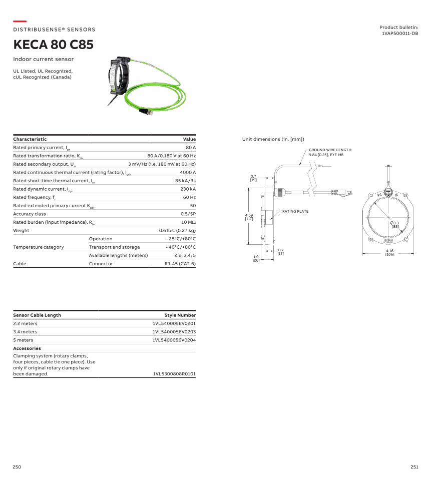
250 251
—D IS TR I B US ENS E® S ENSO R S
KECA 80 C85Indoor current sensor
UL Listed, UL Recognized, cUL Recognized (Canada)
GROUND WIRE LENGTH:9.84 [0.25], EYE M8
RATING PLATE
[19]0.7
[117]4.59
[26]1.0
[17]0.7
[106]4.16
3.3[85]
P2
Unit dimensions (in. [mm])Characteristic Value
Rated primary current, Ipr 80 A
Rated transformation ratio, Kra 80 A/0.180 V at 60 Hz
Rated secondary output, Usr 3 mV/Hz (i.e. 180 mV at 60 Hz)
Rated continuous thermal current (rating factor), Icth 4000 A
Rated short-time thermal current, Ith 85 kA/3s
Rated dynamic current, Idyn 230 kA
Rated frequency, fr 60 Hz
Rated extended primary current Kpcr 50
Accuracy class 0.5/5P
Rated burden (input impedance), Rbr 10 MΩ
Weight 0.6 lbs. (0.27 kg)
Temperature category
Operation - 25°C/+80°C
Transport and storage - 40°C/+80°C
Cable
Available lengths (meters) 2.2; 3.4; 5
Connector RJ-45 (CAT-6)
Sensor Cable Length Style Number
2.2 meters 1VL5400056V0201
3.4 meters 1VL5400056V0203
5 meters 1VL5400056V0204
Accessories
Clamping system (rotary clamps, four pieces, cable tie one piece). Use only if original rotary clamps have been damaged. 1VL5300808R0101
Product bulletin:1VAP500011-DB
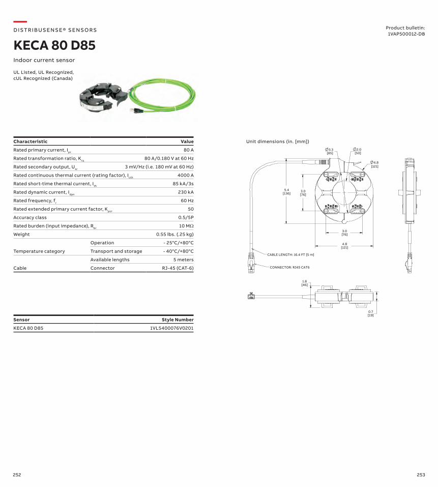
252 253
—D IS TR I B US ENS E® S ENSO R S
KECA 80 D85Indoor current sensor
UL Listed, UL Recognized, cUL Recognized (Canada)
Characteristic Value
Rated primary current, Ipr 80 A
Rated transformation ratio, Kra 80 A/0.180 V at 60 Hz
Rated secondary output, Usr 3 mV/Hz (i.e. 180 mV at 60 Hz)
Rated continuous thermal current (rating factor), Icth 4000 A
Rated short-time thermal current, Ith 85 kA/3s
Rated dynamic current, Idyn 230 kA
Rated frequency, fr 60 Hz
Rated extended primary current factor, Kpcr 50
Accuracy class 0.5/5P
Rated burden (input impedance), Rbr 10 MΩ
Weight 0.55 lbs. (.25 kg)
Temperature category
Operation - 25°C/+80°C
Transport and storage - 40°C/+80°C
Cable
Available lengths 5 meters
Connector RJ-45 (CAT-6)
Sensor Style Number
KECA 80 D85 1VL5400076V0201
Unit dimensions (in. [mm])
CABLE LENGTH: 16.4 FT [5 m]
CONNECTOR: RJ45 CAT6
[136]5.4
[76]3.0
3.3[85]
2.0[50]
4.8[121]
[76]3.0
[121]4.8
[46]1.8
[19]0.7
Product bulletin:1VAP500012-DB
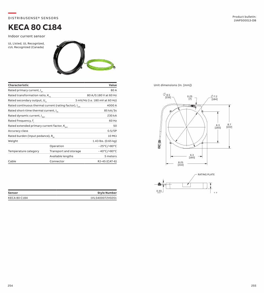
254 255
—D IS TR I B US ENS E® S ENSO R S
KECA 80 C184Indoor current sensor
UL Listed, UL Recognized, cUL Recognized (Canada)
Characteristic Value
Rated primary current, Ipr 80 A
Rated transformation ratio, Kra 80 A/0.180 V at 60 Hz
Rated secondary output, Usr 3 mV/Hz (i.e. 180 mV at 60 Hz)
Rated continuous thermal current (rating factor), Icth 4000 A
Rated short-time thermal current, Ith 85 kA/3s
Rated dynamic current, Idyn 230 kA
Rated frequency, fr 60 Hz
Rated extended primary current factor, Kpcr 50
Accuracy class 0.5/5P
Rated burden (input pedance), Rbr 10 MΩ
Weight 1.43 lbs. (0.65 kg)
Temperature category
Operation - 25°C/+80°C
Transport and storage - 40°C/+80°C
Cable
Available lengths 5 meters
Connector RJ-45 (CAT-6)
Sensor Style Number
KECA 80 C184 1VL5400072V0201
Unit dimensions (in. [mm])
[216]
RATING PLATE
8.5 0.25[7]
7.2[184]
6.3[160]
8.7[222]
6.3[160]
8.25[210]
0.33[8] 1.2
[30]
Product bulletin:1VAP500013-DB
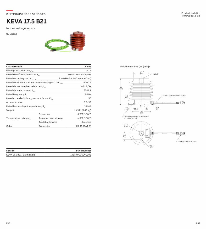
256 257
—D IS TR I B US ENS E® S ENSO R S
KEVA 17.5 B21Indoor voltage sensor
UL Listed
Characteristic Value
Rated primary current, Ipr 80 A
Rated transformation ratio, Kra 80 A/0.180 V at 60 Hz
Rated secondary output, Usr 3 mV/Hz (i.e. 180 mV at 60 Hz)
Rated continuous thermal current (rating factor), Icth 4000 A
Rated short-time thermal current, Ith 85 kA/3s
Rated dynamic current, Idyn 230 kA
Rated frequency, fr 60 Hz
Rated extended primary current factor, Kpcr 50
Accuracy class 0.5/5P
Rated burden (input impedance), Rbr 10 MΩ
Weight 1.43 lb (0.65 kg)
Temperature category
Operation - 25°C/+80°C
Transport and storage - 40°C/+80°C
Cable
Available lengths 5 meters
Connector RJ-45 (CAT-6)
Sensor Style Number
KEVA 17.5 B21, 5.5 m cable 1VL5400060V0302
Unit dimensions (in. [mm])
M20-25
M16-18
CABLE LENGTH: 18 FT (5.5m)
SIZE OF SOCKET FOR RATING PLATE:2.76 x 0.91 [70 x 23]
[130]
3.0
5.1
CONNECTOR: RJ45 CAT6
4.5
[75]
[23]0.9
[3]0.1
[4]0.2
[92]3.6
[20]0.8
[114]
[30]1.2
0.6[15]
Product bulletin:1VAP500014-DB
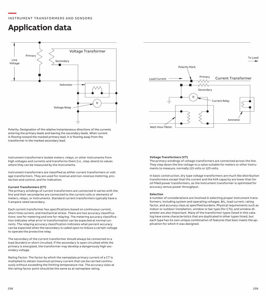
258 259
Instrument transformers isolate meters, relays, or other instruments from high voltages and currents and transforms them (i.e., step-down) to values where they can be measured by the instruments.
Instrument transformers are classified as either current transformers or volt-age transformers. They are used for revenue and non-revenue metering, pro-tection and control, and for indication.
Current Transformers (CT) The primary windings of current transformers are connected in series with the line and their secondaries are connected to the current coils or elements of meters, relays, or instruments. Standard current transformers typically have a 5 ampere rated secondary.
Each current transformer has specifications based on continuous current, short time current, and mechanical stress. There are two accuracy classifica-tions: one for metering and one for relaying. The metering accuracy classifica-tion indicates what error in transformation can be expected at normal cur-rents. The relaying accuracy classification indicates what percent accuracy can be expected when the secondary is called upon to induce a certain voltage to operate the protective relay.
The secondary of the current transformer should always be connected to a load (burden) or short circuited. If the secondary is open circuited while the primary is energized, the transformer may develop a dangerously high sec-ondary voltage.
Rating Factor: The factor by which the nameplate primary current of a CT is multiplied to obtain maximum primary current that can be carried continu-ously without exceeding the limiting temperature rise. The accuracy class at the rating factor point should be the same as at nameplate rating.
Polarity: Designation of the relative instantaneous directions of the currents entering the primary leads and leaving the secondary leads. When current is flowing toward the marked primary lead, it is flowing away from the transformer in the marked secondary lead.
—I NS TRU M ENT TR A NS FO R M ER S A N D S ENSO R S
Application data
LineVoltage
Primary
Secondary
Voltage Transformer
Primary
Secondary
R
R
Voltmeter
Voltage Relay
Watt-Hour Meter
Current Relay
Ammeter
Polarity Mark
Load Current Current Transformer
To Load
Voltage Transformers (VT) The primary windings of voltage transformers are connected across the line. They step down the line voltage to a value suitable for meters or other instru-ments to measure, normally 115 volts or 120 volts. In basic construction, dry type voltage transformers are much like distribution transformers except that the current and the kVA capacity are lower than for oil filled power transformers, as the instrument transformer is optimized for accuracy versus power throughput.
Selection A number of considerations are involved in selecting proper instrument trans-formers, including system and operating voltages, BIL, load current, rating factor, and accuracy class at specified burdens. Physical requirements such as indoor or outdoor installation, window or bar type (for CTs), and window di-ameter are also important. Many of the transformer types listed in this cata-log have some characteristics that are duplicated in other types listed, but each type has its own unique combination of features that best meets the ap-plication for which it was designed.
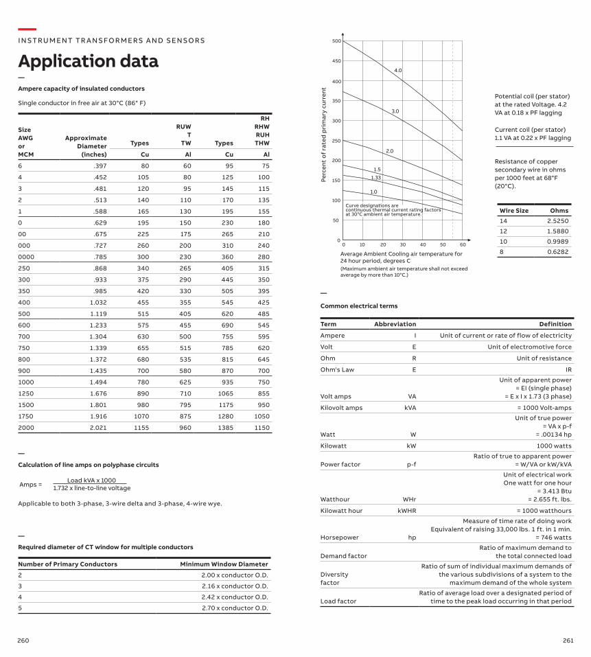
260 261
0 10 20 30 40 50 600
50
100
150
200
250
300
350
400
450
500
1.0
1.33
1.5
2.0
3.0
4.0
Perc
ent
of
rate
d p
rim
ary
curr
ent
Curve designations arecontinuous thermal current rating factorsat 30°C ambient air temperature.
Average Ambient Cooling air temperature for 24 hour period, degrees C(Maximum ambient air temperature shall not exceed average by more than 10°C.)
Potential coil (per stator) at the rated Voltage. 4.2 VA at 0.18 x PF lagging
Current coil (per stator) 1.1 VA at 0.22 x PF lagging
Resistance of copper secondary wire in ohms per 1000 feet at 68°F (20°C).
Wire Size Ohms
14 2.5250
12 1.5880
10 0.9989
8 0.6282
Size AWG or MCM
Approximate Diameter
(inches)
Types
RUW T
TW Types
RH RHW RUH THW
Cu Al Cu Al
6 .397 80 60 95 75
4 .452 105 80 125 100
3 .481 120 95 145 115
2 .513 140 110 170 135
1 .588 165 130 195 155
0 .629 195 150 230 180
00 .675 225 175 265 210
000 .727 260 200 310 240
0000 .785 300 230 360 280
250 .868 340 265 405 315
300 .933 375 290 445 350
350 .985 420 330 505 395
400 1.032 455 355 545 425
500 1.119 515 405 620 485
600 1.233 575 455 690 545
700 1.304 630 500 755 595
750 1.339 655 515 785 620
800 1.372 680 535 815 645
900 1.435 700 580 870 700
1000 1.494 780 625 935 750
1250 1.676 890 710 1065 855
1500 1.801 980 795 1175 950
1750 1.916 1070 875 1280 1050
2000 2.021 1155 960 1385 1150
Single conductor in free air at 30°C (86° F)
Amps = Load kVA x 1000 1.732 x line-to-line voltage
Applicable to both 3-phase, 3-wire delta and 3-phase, 4-wire wye.
Number of Primary Conductors Minimum Window Diameter
2 2.00 x conductor O.D.
3 2.16 x conductor O.D.
4 2.42 x conductor O.D.
5 2.70 x conductor O.D.
—
Calculation of line amps on polyphase circuits
—
Required diameter of CT window for multiple conductors
—
Ampere capacity of insulated conductors
—
Common electrical terms
Term Abbreviation Definition
Ampere I Unit of current or rate of flow of electricity
Volt E Unit of electromotive force
Ohm R Unit of resistance
Ohm's Law E IR
Volt amps VA
Unit of apparent power = EI (single phase)
= E x I x 1.73 (3 phase)
Kilovolt amps kVA = 1000 Volt-amps
Watt W
Unit of true power = VA x p-f
= .00134 hp
Kilowatt kW 1000 watts
Power factor p-fRatio of true to apparent power
= W/VA or kW/kVA
Watthour WHr
Unit of electrical work One watt for one hour
= 3.413 Btu = 2.655 ft. lbs.
Kilowatt hour kWHR = 1000 watthours
Horsepower hp
Measure of time rate of doing work Equivalent of raising 33,000 lbs. 1 ft. in 1 min.
= 746 watts
Demand factorRatio of maximum demand to
the total connected load
Diversity factor
Ratio of sum of individual maximum demands of the various subdivisions of a system to the
maximum demand of the whole system
Load factorRatio of average load over a designated period of
time to the peak load occurring in that period
—I NS TRU M ENT TR A NS FO R M ER S A N D S ENSO R S
Application data
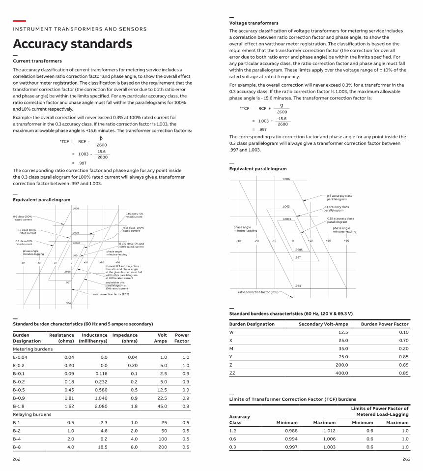
262 263
The accuracy classification of voltage transformers for metering service includes a correlation between ratio correction factor and phase angle, to show the overall effect on watthour meter registration. The classification is based on the requirement that the transformer correction factor (the correction for overall error due to both ratio error and phase angle) be within the limits specified. For any particular accuracy class, the ratio correction factor and phase angle must fall within the parallelogram. These limits apply over the voltage range of ± 10% of the rated voltage at rated frequency.
For example, the overall correction will never exceed 0.3% for a transformer in the 0.3 accuracy class. If the ratio correction factor is 1.003, the maximum allowable phase angle is - 15.6 minutes. The transformer correction factor is:
The corresponding ratio correction factor and phase angle for any point inside the 0.3 class parallelogram will always give a transformer correction factor between .997 and 1.003.
*TCF =
=
=
RCF + g
2600
1.003 +2600-15.6
.997
Burden Designation Secondary Volt-Amps Burden Power Factor
W 12.5 0.10
X 25.0 0.70
M 35.0 0.20
Y 75.0 0.85
Z 200.0 0.85
ZZ 400.0 0.85
phase angleminutes-lagging
phase angleminutes-leading
0.6 accuracy classparallelogram
0.15 accuracy classparallelogram
0.3 accuracy classparallelogram
ratio correction factor (RCF)
.994
1.006
1.003
1.0015
0
.997
.9985
-30 -20 -10 +30+20+10
Accuracy Class Minimum Maximum
Limits of Power Factor of Metered Load-Lagging
Minimum Maximum
1.2 0.988 1.012 0.6 1.0
0.6 0.994 1.006 0.6 1.0
0.3 0.997 1.003 0.6 1.0
The accuracy classification of current transformers for metering service includes a correlation between ratio correction factor and phase angle, to show the overall effect on watthour meter registration. The classification is based on the requirement that the transformer correction factor (the correction for overall error due to both ratio error and phase angle) be within the limits specified. For any particular accuracy class, the ratio correction factor and phase angle must fall within the parallelograms for 100% and 10% current respectively.
Example: the overall correction will never exceed 0.3% at 100% rated current for a transformer in the 0.3 accuracy class. If the ratio correction factor is 1.003, the maximum allowable phase angle is +15.6 minutes. The transformer correction factor is:
*TCF =
=
=
RCF - β
2600
1.003 -260015.6
.997
The corresponding ratio correction factor and phase angle for any point inside the 0.3 class parallelogram for 100% rated current will always give a transformer correction factor between .997 and 1.003.
—Current transformers
0.3 class-10%rated current
0.3 class-100%rated current
0.6 class-100%rated current
to meet 0.3 accuracy class, the ratio and phase angle at the given burden must fallwithin this parallelogramat 100% rated current
and within this parallelogram at 10% rated current
ratio correction factor (RCF)
phase angleminutes-lagging
phase angleminutes-leading
0.15 class- 5%rated current
0.15 class- 100%rated current
0.15S class- 5% and100% rated current
+10
1.00
+20 +30-10-20-30
.997
.9985
0
1.003
1.006
.994
1.0015
—Equivalent parallelogram
Burden Designation
Resistance (ohms)
Inductance (millihenrys)
Impedance (ohms)
Volt Amps
Power Factor
Metering burdens
E-0.04 0.04 0.0 0.04 1.0 1.0
E-0.2 0.20 0.0 0.20 5.0 1.0
B-0.1 0.09 0.116 0.1 2.5 0.9
B-0.2 0.18 0.232 0.2 5.0 0.9
B-0.5 0.45 0.580 0.5 12.5 0.9
B-0.9 0.81 1.040 0.9 22.5 0.9
B-1.8 1.62 2.080 1.8 45.0 0.9
Relaying burdens
B-1 0.5 2.3 1.0 25 0.5
B-2 1.0 4.6 2.0 50 0.5
B-4 2.0 9.2 4.0 100 0.5
B-8 4.0 18.5 8.0 200 0.5
—Standard burden characteristics (60 Hz and 5 ampere secondary)
—Voltage transformers
—Equivalent parallelogram
—Standard burdens characteristics (60 Hz, 120 V & 69.3 V)
—Limits of Transformer Correction Factor (TCF) burdens
—I NS TRU M ENT TR A NS FO R M ER S A N D S ENSO R S
Accuracy standards
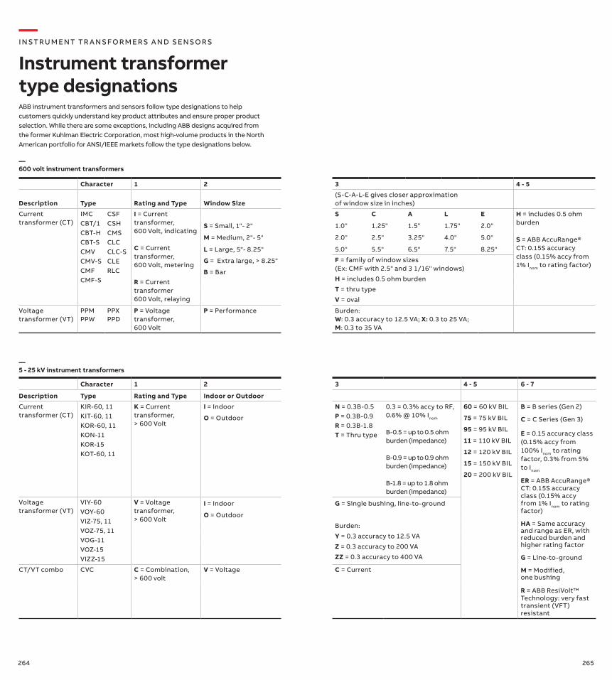
264 265
Character 1 2 3 4 - 5
Description Type Rating and Type Window Size(S-C-A-L-E gives closer approximation of window size in inches)
Current transformer (CT)
IMCCBT/1CBT-HCBT-SCMVCMV-SCMFCMF-S
CSFCSHCMSCLCCLC-SCLERLC
I = Current transformer, 600 Volt, indicating
C = Current transformer, 600 Volt, metering
R = Current transformer 600 Volt, relaying
S = Small, 1"- 2"
M = Medium, 2"- 5"
L = Large, 5"- 8.25"
G = Extra large, > 8.25"
B = Bar
S C A L E H = includes 0.5 ohm burden
S = ABB AccuRange® CT: 0.15S accuracy class (0.15% accy from 1% Inom to rating factor)
1.0" 1.25" 1.5" 1.75" 2.0"
2.0" 2.5" 3.25" 4.0" 5.0"
5.0" 5.5" 6.5" 7.5" 8.25"
F = family of window sizes (Ex: CMF with 2.5" and 3 1/16" windows)
H = includes 0.5 ohm burden
T = thru type
V = oval
Voltage transformer (VT)
PPMPPW
PPXPPD
P = Voltage transformer, 600 Volt
P = Performance Burden:W: 0.3 accuracy to 12.5 VA; X: 0.3 to 25 VA; M: 0.3 to 35 VA
Character 1 2 3 4 - 5 6 - 7
Description Type Rating and Type Indoor or Outdoor
Current transformer (CT)
KIR-60, 11KIT-60, 11KOR-60, 11KON-11KOR-15KOT-60, 11
K = Current transformer, > 600 Volt
I = Indoor
O = Outdoor
N = 0.3B-0.5P = 0.3B-0.9R = 0.3B-1.8T = Thru type
0.3 = 0.3% accy to RF, 0.6% @ 10% Inom
B-0.5 = up to 0.5 ohm burden (impedance)
B-0.9 = up to 0.9 ohm burden (impedance)
B-1.8 = up to 1.8 ohm burden (impedance)
60 = 60 kV BIL
75 = 75 kV BIL
95 = 95 kV BIL
11 = 110 kV BIL
12 = 120 kV BIL
15 = 150 kV BIL
20 = 200 kV BIL
B = B series (Gen 2)
C = C Series (Gen 3)
E = 0.15 accuracy class (0.15% accy from 100% Inom to rating factor, 0.3% from 5% to Inom
ER = ABB AccuRange® CT: 0.15S accuracy class (0.15% accy from 1% Inom to rating factor)
HA = Same accuracy and range as ER, with reduced burden and higher rating factor
G = Line-to-ground
M = Modified, one bushing
R = ABB ResiVolt™ Technology: very fast transient (VFT) resistant
Voltage transformer (VT)
VIY-60VOY-60VIZ-75, 11VOZ-75, 11VOG-11VOZ-15VIZZ-15
V = Voltage transformer, > 600 Volt
I = Indoor G = Single bushing, line-to-ground
O = Outdoor
Burden:
Y = 0.3 accuracy to 12.5 VA
Z = 0.3 accuracy to 200 VA
ZZ = 0.3 accuracy to 400 VA
CT/VT combo CVC C = Combination, > 600 volt
V = Voltage C = Current
—600 volt instrument transformers
—5 - 25 kV instrument transformers
—I NS TRU M ENT TR A NS FO R M ER S A N D S ENSO R S
Instrument transformer type designationsABB instrument transformers and sensors follow type designations to help customers quickly understand key product attributes and ensure proper product selection. While there are some exceptions, including ABB designs acquired from the former Kuhlman Electric Corporation, most high-volume products in the North American portfolio for ANSI/IEEE markets follow the type designations below.
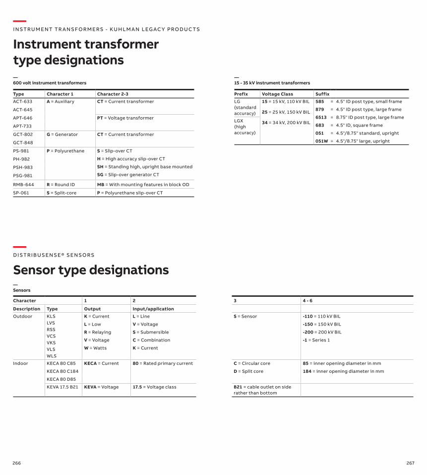
266 267
—I NS TRU M ENT TR A NS FO R M ER S - KU H LM A N LEG AC Y PRO DUC TS
Instrument transformer type designations
Type Character 1 Character 2-3
ACT-633 A = Auxiliary CT = Current transformer
ACT-645
APT-646 PT = Voltage transformer
APT-733
GCT-802 G = Generator CT = Current transformer
GCT-848
PS-981 P = Polyurethane S = Slip-over CT
H = High accuracy slip-over CT
SH = Standing high, upright base mounted
SG = Slip-over generator CT
PH-982
PSH-983
PSG-981
RMB-644 R = Round ID MB = With mounting features in block OD
SP-061 S = Split-core P = Polyurethane slip-over CT
—D IS TR I B US ENS E® S ENSO R S
Sensor type designations
Character 1 2 3 4 - 6
Description Type Output Input/application
Outdoor KLSLVSRSSVCSVKSVLSWLS
K = Current
L = Low
R = Relaying
V = Voltage
W = Watts
L = Line
V = Voltage
S = Submersible
C = Combination
K = Current
S = Sensor -110 = 110 kV BIL
-150 = 150 kV BIL
-200 = 200 kV BIL
-1 = Series 1
Indoor KECA 80 C85
KECA 80 C184
KECA 80 D85
KECA = Current 80 = Rated primary current C = Circular core
D = Split core
85 = inner opening diameter in mm
184 = inner opening diameter in mm
KEVA 17.5 B21 KEVA = Voltage 17.5 = Voltage class B21 = cable outlet on side rather than bottom
—Sensors
—600 volt instrument transformers
—15 - 35 kV instrument transformers
Prefix Voltage Class Suffix
LG (standard accuracy)
15 = 15 kV, 110 kV BIL
25 = 25 kV, 150 kV BIL
34 = 34 kV, 200 kV BIL
585
879
6513
683
051
051W
=
=
=
=
=
=
4.5" ID post type, small frame
4.5" ID post type, large frame
8.75" ID post type, large frame
4.5" ID, square frame
4.5"/8.75" standard, upright
4.5"/8.75" large, upright
LGX (high accuracy)
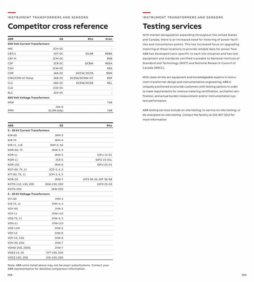
268 269
With market deregulation expanding throughout the United States
and Canada, there is an increased need for metering of power facili-
ties and transmission points. This has increased focus on upgrading
metering at these locations to provide reliable data for power flow.
ABB has developed tests specific to each site situation and has test
equipment and standards certified traceable to National Institute of
Standard and Technology (NIST) and National Research Council of
Canada (NRCC).
With state-of-the-art equipment and knowledgeable experts in instru-
ment transformer design and instrumentation engineering, ABB is
uniquely positioned to provide customers with testing options in order
to meet requirements for revenue metering certification, excitation veri-
fication, and actual burden measurement and/or instrumentation sys-
tem performance.
ABB testing services include on-site testing, in-service on-site testing, or
de-energized on-site testing. Contact the factory at 252-827-3212 for
more information.
ABB GE Ritz Itron
600 Volt Current Transformers
IMC JCH-0C -
CBT/1 JGT-0C DCAB R6BA
CBT-H JCM-0C R6B
CSF JCR-0C DCBW R6SA
CSH JCW-0C R6S
CMF JAK-0C DCCW, DCCB R6M
CMV/CMV-Hi Temp JAB-0C DCDW/DCDW-HT R6P
CLC JAD-0C DCEW/DCEB R6L
CLE JCD-0C -
RLC JCP-0C -
600 Volt Voltage Transformers
PPW T5R
PPMJVA-0
(0.3M only) T6R
ABB GE Ritz
5 - 36 kV Current Transformers
KIR-60 JKM-3
KIR-75 JKM-4
KIR-11, 11E JKM-5, 5A
KOR-60, 75 JKW-3, 4
KOR-11 JKW-5 GIFU 15-01
KON-11 JCK-5 GIFU 15-01L
KOR-15C JKW-6 GIFU 25-01
KOT-60, 75, 11 JCD-3, 4, 5
KIT-60, 75, 11 JCM-3, 4, 5
KOR-20 JKW-7 GIFS 36-55, GIF 36-68
KOTD-110, 150, 200 JKW-150, 200 GIFD 25-03
KOTD-250 JKW-250
5 - 36 kV Voltage Transformers
VIY-60 JVM-3
VIZ-75, 11 JVM-4, 5
VOY-60 JVW-3
VOY-11 JVW-110
VOZ-75, 11 JVW-4, 5
VOG-11 JVW-110
VOZ-11M JVW-5
VOY-12 JVW-6
VOY-15, 15G JVW-6
VOY-20, 20G JVW-7
VOHD-200, 200G JVW-7
VOZZ-15, 20 JVT-150, 200
VOZZ-15G, 20G JVS-150, 200
—I NS TRU M ENT TR A NS FO R M ER S A N D S ENSO R S
Competitor cross reference
—I NS TRU M ENT TR A NS FO R M ER S A N D S ENSO R S
Testing services
Note: ABB units listed above may not be exact substitutions. Contact your ABB representative for detailed comparison information.

—Notes—Notes
1VA
P4
200
01-
TG
Rev
O J
anu
ary
2019
—Contacts
ABB Inc.3022 NC 43 NorthPinetops, NC 27864Phone +1 252 827 3212Fax +1 252 827 4286abb.com/mediumvoltage
We reserve the right to make technical changes or modify the contents of this document without prior notice. With regard to purchase orders, the agreed particulars shall prevail. ABB does not accept any responsibility whatsoever for potential errors or possible lack of information in this document.
We reserve all rights in this document and in the subject matter and illustrations contained therein. Any reproduction, disclo-sure to third parties or utilization of its contents – in whole or in parts – is forbidden without prior written consent of ABB.
Copyright© 2019 ABBAll rights reserved