InstructIons sm / sy / sz / sh compressors -...
4
The compressor must only be used for its designed purpose(s) and within its scope of application (refer to «operating limits»). Consult Application guidelines and da- tasheet available from cc.danfoss.com Under all circumstances, the EN378 (or other applicable local safety regulation) requirements must be fulfilled. The compressor is delivered under nitrogen gas pressure (between 0.3 and 0.7 bar) and hence cannot be connected as is; refer to the «assem- bly» section for further details. The compressor must be handled with caution in the vertical position (maximum offset from the vertical : 15°) FRCC.EI.003.A1.02 © Danfoss Commercial Compressors 03/08 1 INSTRUCTIONS SM / SY / SZ / SH COMPRESSORS A B C K J F G H D E I L Installation and servicing of the compressor by qualified personnel only. Follow these instructions and sound refrigeration engineering practice relating to installation, commissioning, maintenance and service. A: Model B: Serial Number C: Internal Protection D: Supply voltage E: Maximum operating current F: PED Involved side (Low pressure side) G: Lubricant H: Refrigerant I: Locked rotor current J: Ps : Maximum Operating Pressure K: Ts max : Maximum Operating Temperature Ts min : Minimum Operating Temperature L: Manufacturing year R407C Dew point Conditions R404A & R507A R22 T C (°C) T 0 (°C) SM 084 - 185 R134a T C (°C) T 0 (°C) SZ 240, 300, 380 T C (°C) T 0 (°C) SZ 240, 300, 380 T C (°C) T 0 (°C) SY 240, 300, 380 R410A T C (°C) T 0 (°C) SH T C (°C) T 0 (°C) SZ 084 - 185 T C (°C) T 0 (°C) SZ 084 - 185 T C (°C) T 0 (°C) SZ 084 - 185
Transcript of InstructIons sm / sy / sz / sh compressors -...
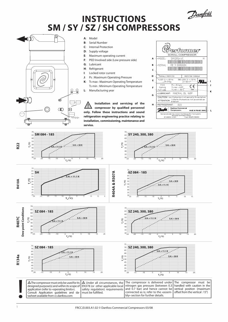
The compressor must only be used for its designed purpose(s) and within its scope of application (refer to «operating limits»). Consult Application guidelines and da-tasheet available from cc.danfoss.com
Under all circumstances, the EN378 (or other applicable local safety regulation) requirements must be fulfilled.
The compressor is delivered under nitrogen gas pressure (between 0.3 and 0.7 bar) and hence cannot be connected as is; refer to the «assem-bly» section for further details.
The compressor must be handled with caution in the vertical position (maximum offset from the vertical : 15°)
FRCC.EI.003.A1.02 © Danfoss Commercial Compressors 03/081
InstructIonssm / sy / sz / sh compressors
A
B
C
K
JF
G
H
D
E I
L
Installation and servicing of the compressor by qualified personnel
only. Follow these instructions and sound refrigeration engineering practice relating to installation, commissioning, maintenance and service.
A: Model
B: Serial Number
c: Internal Protection
D: Supply voltage
e: Maximum operating current
F: PED Involved side (Low pressure side)
G: Lubricant
h: Refrigerant
I: Locked rotor current
J: Ps : Maximum Operating Pressure
K: Ts max : Maximum Operating Temperature
Ts min : Minimum Operating Temperature
L: Manufacturing year
r40
7c
Dew
po
int c
on
dit
ion
s
r40
4A &
r50
7A
r22 T C (°
C)
T0 (°C)
sm 084 - 185
r13
4a
T C (°C)
T0 (°C)
sz 240, 300, 380
T C (°
C)
T0 (°C)
sz 240, 300, 380
T C (°C)
T0 (°C)
sy 240, 300, 380
r41
0A T C (°C)
T0 (°C)
sh
T C (°
C)
T0 (°C)
sz 084 - 185
T C (°C)
T0 (°C)
sz 084 - 185
t c (°c)
t0 (°c)
sz 084 - 185

2 FRCC.EI.003.A1.02 © Danfoss Commercial Compressors 03/08
MDGT
HP180 s
THBP
CONTROL CIRCUIT
F1F1
KM
KM
KM
KA KA
A1
A2
A3
KA
KA
KS
KS
KS
L1 L3 L2
Q1
F2
T1
T3
T2
LLSV KS
cc
thM
A1
A3
A2
mpm
s
sh 090 - 105 - 120 - 140 - 161
sm 084 - 090 - 100 - 110 - 120 - 124 - 147 - 148 - 161
sz 084 - 090 - 100 - 110 - 120 - 148 - 161
sm 115 - 125 - 160 - 175 - 185 sz 115 - 125 - 160 - 175 - 185
sh 240 - 300 - 380 sy 240 - 300 - 380 sz 240 - 300 - 380
These Performer® compressors
are protected against overheating
and overloading by an internal
safety motor protector. However,
an external manual reset overload
protector is recommended for
protecting the circuit against over-
current.
These Performer® compressors
are provided with a bimetallic sin-
gle pole single throw thermostat
which is located in the motor win-
dings. Because the thermostat is
an automatic reset device, it must
be wired in a lockout safety circuit
with a manual reset to restart the
unit. For over-current protection,
an external manual reset overload
protector must be used.
The “must trip” value of these
overload relays must be set in ac-
cordance with power line sizing
and design and shall never exceed
the “A max.” value stamped on the
nameplate.
These Performer® compressors
motors are protected by an ex-
ternal module protecting against
phase loss/reversal, over heating
and high current draw.
Instructions

FRCC.EI.003.A1.02 © Danfoss Commercial Compressors 03/08 3
A1A3
A2
MPM
12 14 11N 21L1
S
sh 180
This Performer® compressor motor
is protected by an external module
protecting against overheating and
high current draw.
Control circuit .......................................................... CCControl device ..........................................................THOptional short cycle timer (3 min) .................180 sControl relay ............................................................ KALiquid Line Solenoid valve ................................ LLSVCompressor contactor .......................................... KM
Safety lock out relay ................................................KSPump-down control & L.P. switch ....................... BPH.P. safety switch ....................................................HPFused disconnect ....................................................Q1Fuses ...........................................................................F1External overload protection ................................F2
Compressor motor ...................................................MMotor safety thermostat .................................... thMDischarge gas thermostat .................................DGTMotor Protection Module ................................ MPMThermistor chain........................................................ S
Legend:
All Wiring diagrams are with pump-down cycle
Instructions
1 – Introduction
These instructions pertain to the Performer®
SM, SY, SZ & SH scroll compressors used for air-
conditioning systems. They provide necessary
information regarding safety and proper usage
of this product.
2 – Handling and storage
• Handle the compressor with care. Use the
dedicated handles in the packaging. Use the
compressor lifting lug and use appropriate
and safe lifting equipment.
• Store and transport the compressor in an
upright position.
• Storethecompressorbetween-35°Cand50°C.
• Don’texposethecompressorandthepacka-
ging to rain or corrosive atmosphere.
3 – Safety measures before assembly
Never use the compressor in a flammable
atmosphere.
• The compressor ambient temperature may
not exceed 50°C during off-cycle.
• Mount the compressor on a horizontal flat
surface with less than 3° slope.
• Verify thatthepowersupplycorrespondsto
the compressor motor characteristics (see
nameplate).
• WheninstallingSZorSH,useequipmentspe-
cifically reserved for HFC refrigerants which
was never used for CFC or HCFC refrigerants.
• Usecleananddehydratedrefrigeration-grade
copper tubes and silver alloy brazing material.
• Usecleananddehydratedsystemcomponents.
• Thepipingconnectedtothecompressormustbe
flexible in 3 dimensions to dampen vibrations.
4 – Assembly
• InparallelassembliesofSH,SM124andSM147
the compressor requires a rigid mounting on
the rails. Use the rigid spacers from the tandem
mounting kit or the rigid spacers delivered
with dedicated tandem compressors.
• Slowly release the nitrogen holding charge
through the schrader port.
• Remove the gaskets when brazing rotolock
connectors.
• Alwaysusenewgasketsforassembly.
• Connect the compressor to the system as
soon as possible to avoid oil contamination
from ambient moisture.
• Avoidmaterialenteringintothesystemwhile
cutting tubes. Never drill holes where burrs
cannot be removed.
• Brazewithgreatcareusingstate-of-the-arttech-
nique and vent piping with nitrogen gas flow.
• Connect the requiredsafetyandcontrolde-
vices.Whentheschraderportisusedforthis,
remove the internal valve.
• Do not exceed the maximum tightening
torque for rotolock connections:
Rotolock connections Tightening torque1” rotolock 80 Nm1 1/4 “ rotolock 90 Nm1 3/4” rotolock 110 Nm2 1/4” rotolock 130 Nm.
5 – Leak detection
Never pressurize the circuit with oxygen or
dry air. This could cause fire or explosion.
• SM084to185,SY380,SZ084to185,SZ380,SH
090 to 180: Pressurize the system on HP side
first and then on LP side. Never let the pres-
sure on LP side exceed the pressure on HP side
with more than 5 bar. Such pressure difference
could cause internal compressor damage.
• SY 240 & 300, SZ 240 & 300, SH 240 to 380:
Pressurize the system slowly on LP side. The
pressure increase from 0 up to the maximum
system test pressure at LP side shall take at
least2minutes.Whenthe2minutestimespan
is not respected, the pressure on LP side could
exceed the pressure on HP side with more than
5 bar and cause internal compressor damage.
• Donotusedyeforleakdetection.
• Performaleakdetectiontestonthecomplete
system.
• The lowsidetestpressuremustnotexceed20
bar for SM/SY/SZ and 30 bar for SH compressors.
• Whenaleakisdiscovered,repairtheleakand
repeat the leak detection.
6–Vacuumdehydration
• Never use the compressor to evacuate the
system.
• ConnectavacuumpumptoboththeLP&HP
sides.
• Pulldownthesystemunderavacuumof500
µm Hg (0.67 mbar) absolute.
• Donotuseamegohmmeternorapplypower
to the compressor while it is under vacuum as
this may cause internal damage.
7 – Electrical connections
• Switchoffandisolatethemainpowersupply.
See overleaf for wiring details.
• Allelectricalcomponentsmustbeselectedasper
local standards and compressor requirements.
• Refertopage2forelectricalconnectionsdetails.
• ThePerformer®scrollcompressoronlyworks
correctly in one rotation direction. Line pha-
ses L1, L2, L3 must absolutely be connected

4 FRCC.EI.003.A1.02 © Danfoss Commercial Compressors 03/08
Instructions
to compressor terminals T1, T2, T3 to avoid
reverse rotation.
• Useø4.8mm(3/16”)screwsand¼”ringter-
minals for the power connection. Fasten with
3 Nm torque.
• Thethermostatconnection(ifpresent)isa¼”
AMP-AWEspadeconnector.
• Thecompressormustbeconnectedtoearth
with the 5 mm earth terminal screw.
8 – Filling the system
• Keepthecompressorswitchedoff.
• SM084to185,SY380,SZ084to185,SZ380,SH
090 to 180: Fill the refrigerant in liquid phase
into the condenser or liquid receiver. The char-
ge must be as close as possible to the nominal
system charge to avoid low pressure operation
and excessive superheat. Never let the pressure
on LP side exceed the pressure on HP side with
more than 5 bar. Such pressure difference could
cause internal compressor damage.
• SY240&300,SZ240&300,SH240to380:Fill
the refrigerant slowly in liquid phase into the
LP side of the system. The charge must be as
close as possible to the nominal system charge
to avoid low pressure operation and excessive
superheat. The pressure increase from 0 up
to the full system charge shall take at least 2
minutes.Whenthe2minutestimespanisnot
respected, the pressure on LP side could ex-
ceed the pressure on HP side with more than
5 bar and cause internal compressor damage.
• Keeptherefrigerantchargebelowtheindica-
ted charge limits if possible. Above this limit;
protect the compressor against liquid flood-
back with a pump-down cycle or suction line
accumulator.
• Neverleavethefillingcylinderconnectedto
the circuit.
Compressor models Refrigerant charge limit (kg)
SM/SZ 084, 090, 100 8.5SM/SZ 110, 120 10SM/SZ 115, 125 11SM/SZ 148, 160, 161 12.5SM/SZ 175, 185 13.5SY/SZ 240 16SY/SZ 380 20SH 090 5.9SH 105, 120, 140, 161 7.9SH 180, 240, 300 13.5SH 380 14.5
9–Verificationbeforecommissioning
Use safety devices such as safety pressure
switch and mechanical relief valve in complian-
ce with both generally and locally applicable re-
gulations and safety standards. Ensure that they
are operational and properly set.
Check that the settings of high-pressure swit-
chesandreliefvalvesdon’texceedthemaximum
service pressure of any system component.
• A low-pressure switch is recommended to
avoid vacuum operation. Minimum setting
for SM/SY/SZ: 1.5 bar (absolute). Minimum
setting for SH: 1.6 bar (absolute).
• Verifythatallelectricalconnectionsarepro-
perly fastened and in compliance with local
regulations.
• Whenacrankcaseheaterisrequired,itmustbe
energized at least 12 hours before initial start-
up and start-up after prolonged shutdown.
Exception: Due to specific R410A behavior it
is not recommended to energize crankcase
heaters on SH compressors before initial
startup.
10 – Start-up
• Neverstartthecompressorwhennorefrige-
rant is charged.
• Allservicevalvesmustbeintheopenposition.
• BalancetheHP/LPpressure.
• Energizethecompressor.Itmuststartprompt-
ly. If the compressor does not start, check wi-
ring conformity and voltage on terminals.
• Eventual reverse rotation can be detected
by following phenomena; the compressor
doesn’tbuilduppressure, ithasabnormally
high sound level and abnormally low power
consumption. In such case, shut down the
compressor immediately and connect the
phases to their proper terminals. Most Per-
former® scroll compressors are protected
against reverse rotation either by an internal
reverse rotation protection or by the external
electronic protection module. They will shut
off automatically. Only SH 090 to 161 and SM
124, 147 have no reverse rotation protection.
Prolonged reverse rotation over 6 hours will
damage these compressors.
• Iftheinternaloverloadprotectortripsout(SM/
SZ 084, 090, 100, 110, 120, 124, 147, 148, 161
and SH 090, 105, 120, 140, 161), it must cool
down to 60°C to reset. Depending on ambient
temperature, this may take up to several hours.
• Iftheinternalpressurereliefvalveisopened
(SY/SZ 240, 300, 380 and SH 380), the com-
pressor sump will be warm and the compres-
sor will trip out on the motor protector.
11 – Check with running compressor
• Checkcurrentdrawandvoltage.
• Check suction superheat to reduce risk of
slugging.
• Observe the oil level in the sight glass for
about 60 minutes to ensure proper oil return
to the compressor.
• Respecttheoperatinglimits.
• Checkalltubesforabnormalvibration.Move-
ments in excess of 1.5 mm require corrective
measures such as tube brackets.
• When needed, additional refrigerant in liquid
phase may be added in the low-pressure side as
far as possible from the compressor. The com-
pressor must be operating during this process.
• Donotoverchargethesystem.
• Neverreleaserefrigeranttoatmosphere.
• Before leavingthe installationsite,carryout
a general installation inspection regarding
cleanliness, noise and leak detection.
• Recordtypeandamountofrefrigerantcharge
as well as operating conditions as a reference
for future inspections.
12 – Maintenance
Internal pressure and surface temperature
are dangerous and may cause permanent injury.
Maintenance operators and installers require
appropriate skills and tools. Tubing temperature
may exceed 100°C and can cause severe burns.
Ensure that periodic service inspections to
ensure system reliability and as required by local
regulations are performed.
To prevent system related compressor problems,
following periodic maintenance is recommended:
• Verifythatsafetydevicesareoperationaland
properly set.
• Ensurethatthesystemisleaktight.
• Checkthecompressorcurrentdraw.
• Confirmthatthesystemisoperatinginaway
consistent with previous maintenance re-
cords and ambient conditions.
• Check thatall electrical connectionsare still
adequately fastened.
• Keepthecompressorcleanandverifytheab-
sence of rust and oxidation on the compres-
sor shell, tubes and electrical connections.
13-Warranty
Always transmit the model number and serial num-
ber with any claim filed regarding this product.
The product warranty may be void in following
cases:
• Absenceofnameplate.
• Externalmodifications; in particular, drilling,
welding, broken feet and shock marks.
• Compressoropenedorreturnedunsealed.
• Rust,water or leakdetectiondye inside the
compressor.
• Useofarefrigerantorlubricantnotapproved
by Danfoss.
• Any deviation from recommended instruc-
tions pertaining to installation, application or
maintenance.
• Useinmobileapplications.
• Useinexplosiveatmosphericenvironment.
• Nomodelnumberorserialnumbertransmit-
ted with the warranty claim.
14 – Disposal
Danfoss recommends that compressors
and compressor oil should be recycled
by a suitable company at its site.


![GEA-NZ v3.2 Application and Software Services Reference ... · application name. Merged with A1.02 Financial Management Information System [FMIS] A1.16 Payroll A1.03.05 Payroll Promoted](https://static.fdocuments.in/doc/165x107/601607e2f6b98c5cd11968da/gea-nz-v32-application-and-software-services-reference-application-name-merged.jpg)