InstructIons VzH compressors -...
4
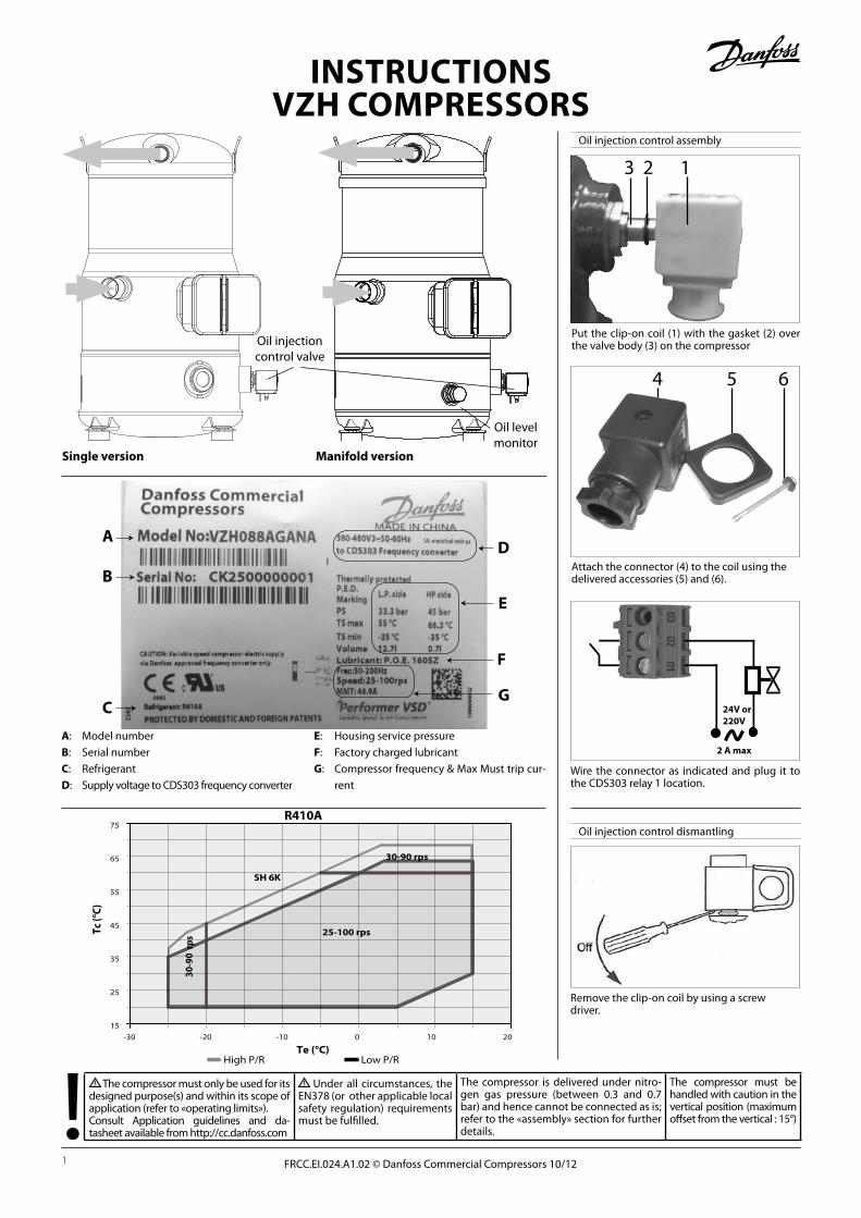
The compressor must only be used for its designed purpose(s) and within its scope of application (refer to «operating limits»). Consult Application guidelines and da- tasheet available from http://cc.danfoss.com Under all circumstances, the EN378 (or other applicable local safety regulation) requirements must be fulfilled. The compressor is delivered under nitro- gen gas pressure (between 0.3 and 0.7 bar) and hence cannot be connected as is; refer to the «assembly» section for further details. The compressor must be handled with caution in the vertical position (maximum offset from the vertical : 15°) FRCC.EI.024.A1.02 © Danfoss Commercial Compressors 10/12 1 Oil injection control assembly Put the clip-on coil (1) with the gasket (2) over the valve body (3) on the compressor 32 1 4 5 6 Attach the connector (4) to the coil using the delivered accessories (5) and (6). 24V or 220V 2 A max Wire the connector as indicated and plug it to the CDS303 relay 1 location. Oil injection control dismantling Remove the clip-on coil by using a screw driver. INSTRUCTIONS VZH COMPRESSORS Oil injection control valve Single version Oil level monitor Manifold version A: Model number B: Serial number C: Refrigerant D: Supply voltage to CDS303 frequency converter E: Housing service pressure F: Factory charged lubricant G: Compressor frequency & Max Must trip cur- rent E F C D A B G 15 25 35 45 55 65 75 Tc (°C) 30-90 rps Te (°C) -30 -20 -10 0 10 20 30-90 rps 25-100 rps SH 6K High P/R Low P/R R410A
Transcript of InstructIons VzH compressors -...
The compressor must only be used for its designed purpose(s) and within its scope of application (refer to «operating limits»). Consult Application guidelines and da-tasheet available from http://cc.danfoss.com
Under all circumstances, the EN378 (or other applicable local safety regulation) requirements must be fulfilled.
The compressor is delivered under nitro-gen gas pressure (between 0.3 and 0.7 bar) and hence cannot be connected as is; refer to the «assembly» section for further details.
The compressor must be handled with caution in the vertical position (maximum offset from the vertical : 15°)
FRCC.EI.024.A1.02 © Danfoss Commercial Compressors 10/121
Oil injection control assembly
Put the clip-on coil (1) with the gasket (2) over the valve body (3) on the compressor
3 2 1
4 5 6
Attach the connector (4) to the coil using the delivered accessories (5) and (6).
24V or220V
2 A max
Wire the connector as indicated and plug it to the CDS303 relay 1 location.
Oil injection control dismantling
Remove the clip-on coil by using a screw driver.
InstructIonsVzH compressors
Oil injection control valve
single version
Oil level monitor
manifold version
A: Model numberB: Serial numberc: RefrigerantD: Supply voltage to CDS303 frequency converter
e: Housing service pressureF: Factory charged lubricantG: Compressor frequency & Max Must trip cur-
rent
E
F
C
DA
B
G
15
25
35
45
55
65
75
Tc (°
C)
30-9
0 rp
s
Te (°C)-30 -20 -10 0 10 20
30-90 rps
25-100 rps
SH 6K
High P/R Low P/R
r410A

2 FRCC.EI.024.A1.02 © Danfoss Commercial Compressors 10/12
Basic connections
- Depending on the frequency converter version, the physical position of individual connectors may differ from below diagram.
- Always make sure that the compressor termi-nals T1, T2, T3 are connected to the frequency converter terminals 96, 97, 98 respectively.
- The compressor motor cable must be shielded and the armoured part must be connected to ground on both cable ends; at the side of the compressor and at the side of the frequency converter.
- Use an EMC cable gland for cable installation and perfect grounding; The metallic terminal box of the compressor has a paint-free surface around the connection hole for better conductivity.
- A low pressure safety switch is mandatory to avoid compressor vacuum operation.
- At start-up, verify that the compressor rotates in the right direction and pumps.
230 V or 24V~
2 A maxRE
LAY
1
L1 91 L1 W 98 T3L2 92 L2 V 97 T2L3 93 L3 U 96 T1
95 PE PE 99
39 39 Ana out COM42 42 Ana out +50 50 Ana out +10 V NC 0353 53 Ana in 0 ± 10 V NO 0254 54 Ana in 0 ± 10 V COM 0155 55 Ana in COM
NC 06NO 05
12 12 +24V COM 0413 13 +24V18 18 Dig in19 19 Dig in27 27 Dig in/out29 29 Dig in/out32 32 Dig in N- RS485 69 6933 33 Dig in P+ RS485 68 6820 20 Dig in COM COM RS485 61 6137 37 Dig in
RE
LAY
2CDS3
03
Legends: Ana: AnalogueDig: Digitalin: Inputout: OutputCOM: CommonNC: Normally-closedNO: Normally-open
Open loop Process loop91, 92, 93: 3 Phase mains input X X95: Earth X X39, 42 Analogue output - -50: Analogue output - -53: PLC+ (0 to 10 V) X -54: Sensor - - X55: PLC- X -12: HP/LP switch X X12: External On/Off (NO) X X13: Factory bridged to 37 X X13: Sensor + - X18: External On/Off (NO) X X19: Digital input - -27: HP/LP switch (NC) / safety devices X X29: Digital input/output - -32, 33 Digital input - -20: Digital input Common - -37: Factory bridged to 13 X X98: To compressor terminal T3 X X97: To compressor terminal T2 X X96: To compressor terminal T1 X X99: To compressor earth connection X X02, 01: Relay 1 to oil solenoid valve X X06, 05, 04: Relay 2 - -69, 68: RS485 Bus - -61: RS485 Bus Common - -
The CDS303 frequency converter is factory pre-set with parameters for the open loop control principle. The process loop control principle can be selected by changing parameters in the «Quick menu».
Open loop: 0 - 10 V control Frequency converter in slave mode
Process loop: 4 - 20 mA controlFrequency converter under own PID controller
Oil level switch assembly
Electrical connections / Wiring
Install the screw-in optical part on oil level switch port. (Factory preset for manifold version VZH compressor.)
31
42
1: Power supply wire2: Power supply wire
3: Output wire4: Not used
Install the electrical part on optical part. Make sure the cable outlet downside vertically
see at the correct diagram corresponding to different power supply models for proper wiring
1
OVDC
24VDC
2
3Sensor
ExternalLoad / Relay
24VDC MODEL
1
OVAC
24VAC
2
3Sensor
ExternalLoad / Relay
24VAC MODEL
1
N
L
2
3Sensor
ExternalLoad / Relay
230VAC MODEL
- : Optional connection X : Mandatory connection
Instructions

1 - IntroductionThese instructions pertain to the VZH Variable Speed scroll compressors used for A/C systems. They provide necessary information regarding safety and proper usage of this product.
2 – Handling and storage • Handle the compressor with care. Use the
dedicated handles in the packaging. Use the compressor lifting lug and use appropriate and safe lifting equipment.
• Store and transport the compressor in an upright position.
• Store the compressor between -35°C and 55°C. • Don’t expose the compressor and the packa-
ging to rain or corrosive atmosphere.
3 – Safety measures before assembly Never use the compressor in a flammable
atmosphere.
• The compressor ambient temperature may not exceed 50°C during off-cycle.
• Mount the compressor on a horizontal flat surface with less than 3° slope.
• The compressor can only be supplied by a frequency converter. Make sure that the frequency converter is the dedicated one for the compressor (power size and voltage: input & output). Parameter 1.13 of the frequency converter lists the possible combinations of compressors, frequency converters and refrigerants.
• When installing a VZH, use equipment specifi-cally reserved for HFC refrigerants which was never used for CFC refrigerants.
• Use clean and dehydrated refrigeration-grade copper tubes and silver alloy brazing material.
• Use clean and dehydrated system components. • The piping connected to the compressor must
be flexible in 3 dimensions to dampen vibrations. • Make sure the installation is equipped with
high-pressure safety components (e.g. pressure switch, pressure relief valve) to prevent against the bursting of pressure-containing compo-nents.
4 - Assembly • Slowly release the nitrogen holding charge
through the schrader port. • Connect the compressor to the system as
soon as possible to avoid oil contamination from ambient moisture.
• Avoid material entering into the system while cutting tubes. Never drill holes where burrs cannot be removed.
• Braze with great care using state-of-the-art tech-nique and vent piping with nitrogen gas flow.
• Connect the required safety and control de-vices. When the schrader port is used for this, remove the internal valve.
5 – Leak detection Never pressurize the circuit with oxygen or
dry air. This could cause fire or explosion.
• Do not use dye for leak detection. • Perform a leak detection test on the complete
system. • The low side test pressure must not exceed 30 bar. • When a leak is discovered, repair the leak and
repeat the leak detection.
6 – Vacuum dehydration • Never use the compressor to evacuate the system. • Connect a vacuum pump to both the LP & HP sides. • Evacuate the system to a pressure of 500 µm
Hg (0.67 mbar) absolute. • Do not use a megohmmeter nor apply power
to the compressor while it is under vacuum as this may cause internal damage.
7 – Electrical connections • Switch off and isolate the main power supply.
See previous page for wiring details. • The compressor is protected against excess
current by the frequency converter. Follow local regulations regarding power line protection. The compressor must be connected to ground.
• All electrical components must be selected as per local standards and compressor requirements.
• Please refer to drawings for typical wiring connec-tions and examine the specific wiring diagram located in the frequency converter package. For further details, refer to the application guidelines.
• Follow very closely the installation instruction for the frequency converter:
- Mounting: The base frame of the frequency converter must be very well fixed to the support to ensure a very good continuity between the ground potential of all electrical panels and electrical boxes of the system.
- Wiring: All control wires have to be of a screee-ned design. The cable for electrical motor sup-ply has to be of a shielded design as well. Cor-rect earthing of the shield cover has to be done using the method shown on drawings, every time this one has to be earthed on each end of the cables. Distinct cable trays must be used for control and motor supply.
• The frequency converter ensures direct motor protection and the factory set parameters are such to protect the motor over all current mal-functions. An external overload is not necessary.
• Set the frequency converter parameters in accordance with Danfoss recommendations for the CDS303 frequency converter and VZH variable speed compressor.
8 – Filling the system • Keep the compressor switched off. • Fill the refrigerant in liquid phase into the
outlet side of the condenser or liquid receiver. The charge must be as close as possible to the nominal system charge to avoid low pressure operation and excessive superheat.Compressor Refrigerant charge limit (kg)
VZH088 5.9 VZH117 7.9 VZH170 13.5
Above this limit; protect the compressor against liquid flood-back with a pump-down cycle not lower than 2.3 bar (g) or a suction line accumu-lator.
• Never leave the filling cylinder connected to the circuit to avoid overfilling.
9 – Verification before commissioning Use safety devices such as safety pressure
switch and mechanical relief valve in compliance with both generally and locally applicable regu-lations and safety standards. Ensure that they are operational and properly set.
Check that the settings of high-pressure switches and relief valves don’t exceed the maximum service pressure of any system com-ponent.
• A low-pressure switch is mandatory to avoid vacuum operation. Minimum setting 1.5 bar (g).
• Verify that all electrical connections are properly fastened and in compliance with local regula-tions.
• The crankcase heater function is factory preset to "disabled". It must not be used for VZH170 but could be used for VZH088/117. In default case, an external crankcase heater is required.
• After comissioning it is strongly recommended to keep the frequency converter always energized.
10 – Start-up • All service valves must be in the open position. • Balance the HP/LP pressure. • Energize the compressor. It must start promptly. • If the compressor doesn’t start, verify that the
compressor is hooked up to the frequency converter; check the power lead connections. If these verifications reveal no abnormality, check the motor windings with an ohmmeter.
• Check the frequency converter control pa-nel: If any alarm is displayed check the wiring and in particular the polarity of the control cables. If an alarm is shown, refer to the fre-quency converter application manual. Verify in particular the combination of compressor, frequency converter and refrigerant.
• Check current draw and voltage levels on the mains. The values for the compressor elec-trical motor can be directly displayed on the frequency converter control panel.
• The optimum compressor suction superheat is around 6K. The maximum allowed super- heat is 30K.
11 – Check with running compressor • Check current draw and voltage. • Check suction superheat to reduce risk of
slugging. • Observe the oil level at start and during opera-
tion to confirm that the oil level remains visible.Excess foaming in oil sight glass indicates refri-gerant on the sump.
• Monitor the oil sight glass for 1 hour after sys-tem equilibrium to ensure proper oil return to the compressor. This oil check has to be done over the speed range to guarantee:
- a good oil return at low speed with mini-mum gas velocity.
- a good oil management at high speed with maximum oil carry over.
• Respect the operating limits. • Check all tubes for abnormal vibration. Move-
ments in excess of 1.5 mm require corrective measures such as tube brackets.
• When needed, additional refrigerant in the liquid phase may be added in the low-pressure side as far as possible from the compressor. The compressor must be operating during this process.
• Do not overcharge the system. • Never release refrigerant to the atmosphere. • Before leaving the installation site, carry out
a general installation inspection regarding cleanliness, noise and leak detection.
• Record type and amount of refrigerant charge as well as operating conditions as a reference for future inspections.
• Compressor failure to build up pressure: Check all bypass valves in the system to ensure that none of these has been opened. Also check that all solenoid valves are in their proper position.
• Abnormal running noise: Ensure the absence of any liquid flood-back to the compressor by means of measuring the return gas superheat and compressor sump temperature. The sump should be at least 6K above the satura-ted suction temperature under steady-state operating conditions.
• The high-pressure switch trips out: Check condenser operations (condenser cleanliness, fan operation, water flow and water pressure valve, water filter, etc.). If all these are OK, the problem may be due to either refrige-rant overcharging or the presence of a non-condensable (e.g. air, moisture) in the circuit.
• The low-pressure switch trips out: Check evapo-rator operations (coil cleanliness, fan operations, water flow, water filter, etc.), liquid refrigerant
FRCC.EI.024.A1.02 © Danfoss Commercial Compressors 10/12 3
Instructions

flow and pressure drops (solenoid valve, filter dryer, expansion valve, etc.), refrigerant charge.
• Low refrigerant charge: The correct refrigerant charge is given by the liquid sight glass indication, the condenser delta T in relation to the refrige-rant pressure tables (pressure-temperature), the superheat and the sub-cooling, etc. (if additional charge is deemed necessary, refer to section 8).
• Compressor short cycling: The number of cycles shall never exceed 12 starts per hour.
12 - Maintenance Internal pressure and surface temperature
are dangerous and may cause permanent injury.Maintenance operators and installers require appropriate skills and tools. Tubing and com-presssor upper shell temperature may exceed 100°C and can cause severe burns.
Ensure that periodic service inspections to ensure system reliability and as required by local regulations are performed.
To prevent system related compressor problems, following periodic maintenance is recommended: • Verify that safety devices are operational and
properly set. • Ensure that the system is leak tight. • Check the compressor current draw. • Confirm that the system is operating in a way
consistent with previous maintenance re-cords and ambient conditions.
• Check that all electrical connections are still adequately fastened.
• Keep the compressor clean and verify the ab-sence of rust and oxidation on the compres-sor shell, tubes and electrical connections.
• Check the internal temperature of the fre-quency converter on its display and the coo-ling air flow.
• Faults are logged in the frequency converter memory and can be displayed. This can help to evaluate and improve parameters of the frequency converter or of the system itself.
13 - WarrantyAlways transmit the model number and serial number with any claim filed regarding this pro-duct.
Use the fault memory of the frequency conver-ter to recover the fault descriptions before ini-tializing the system and even before shutting off the power.
The product warranty may be void in following cases: • Absence of nameplate. • External modifications; in particular, drilling,
welding, broken feet and shock marks. • Compressor opened or returned unsealed. • Rust, water or leak detection dye inside the
compressor. • Use of a refrigerant or lubricant not approved
by Danfoss. • Any deviation from recommended instruc-
tions pertaining to installation, application or maintenance.
• Use in mobile applications. • Use in explosive atmospheric environment. • No model number or serial number transmit-
ted with the warranty claim.
14 – DisposalDanfoss recommends that compressors, frequency converters and compressor oil should be recycled by a suitable company.
Danfoss Commercial Compressors http://cc.danfoss.comDanfoss can accept no responsibility for possible errors in catalogues, brochures and other printed material. Danfoss reserves the right to alter its products without notice. This also applies to products already on order provided that such alterations can be made without subsequential changes being necessary in specifications already agreed.All trademarks in this material are property of the respective companies. Danfoss and the Danfoss logotype are trademarks of Danfoss A/S. All rights reserved.
FRCC.EI.024.A1.02 - October 2012 Copyright Danfoss Commercial Compressors - 10/12
Instructions