Installation Manual - - APC USA · Installation Manual Air Economizer ... Install the Module Screw...
30
Installation Manual Air Economizer EcoBreeze™ Module ACEC101SE, ACEC200SE, ACEC201SE 990-5221C-001 Publication Date: October 2015
Transcript of Installation Manual - - APC USA · Installation Manual Air Economizer ... Install the Module Screw...

Installation Manual
Air Economizer
EcoBreeze™ Module
ACEC101SE, ACEC200SE, ACEC201SE990-5221C-001
Publication Date: October 2015

Schneider Electric IT Corporation Legal DisclaimerThe information presented in this manual is not warranted by the Schneider Electric IT Corporation to be authoritative, error free, or complete. This publication is not meant to be a substitute for a detailed operational and site specific development plan. Therefore, Schneider Electric IT Corporation assumes no liability for damages, violations of codes, improper installation, system failures, or any other problems that could arise based on the use of this Publication.
The information contained in this Publication is provided as is and has been prepared solely for the purpose of evaluating data center design and construction. This Publication has been compiled in good faith by Schneider Electric IT Corporation. However, no representation is made or warranty given, either express or implied, as to the completeness or accuracy of the information this Publication contains.
IN NO EVENT SHALL SCHNEIDER ELECTRIC IT CORPORATION, OR ANY PARENT, AFFILIATE OR SUBSIDIARY COMPANY OF SCHNEIDER ELECTRIC IT CORPORATION OR THEIR RESPECTIVE OFFICERS, DIRECTORS, OR EMPLOYEES BE LIABLE FOR ANY DIRECT, INDIRECT, CONSEQUENTIAL, PUNITIVE, SPECIAL, OR INCIDENTAL DAMAGES (INCLUDING, WITHOUT LIMITATION, DAMAGES FOR LOSS OF BUSINESS, CONTRACT, REVENUE, DATA, INFORMATION, OR BUSINESS INTERRUPTION) RESULTING FROM, ARISING OUT, OR IN CONNECTION WITH THE USE OF, OR INABILITY TO USE THIS PUBLICATION OR THE CONTENT, EVEN IF SCHNEIDER ELECTRIC IT CORPORATION HAS BEEN EXPRESSLY ADVISED OF THE POSSIBILITY OF SUCH DAMAGES. SCHNEIDER ELECTRIC IT CORPORATION RESERVES THE RIGHT TO MAKE CHANGES OR UPDATES WITH RESPECT TO OR IN THE CONTENT OF THE PUBLICATION OR THE FORMAT THEREOF AT ANY TIME WITHOUT NOTICE.
Copyright, intellectual, and all other proprietary rights in the content (including but not limited to software, audio, video, text, and photographs) rests with Schneider Electric IT Corporation or its licensors. All rights in the content not expressly granted herein are reserved. No rights of any kind are licensed or assigned or shall otherwise pass to persons accessing this information.
This Publication shall not be for resale in whole or in part.

Table of Contents
Safety.................................................................................1Important Safety Information . . . . . . . . . . . . . . . . . . . . . . . . . . . . . . . . . 1
Safety During Installation . . . . . . . . . . . . . . . . . . . . . . . . . . . . . . . . . . . . 2
General Information...........................................................3Inspecting the Equipment . . . . . . . . . . . . . . . . . . . . . . . . . . . . . . . . . . . . 3
Storing the equipment before installation . . . . . . . . . . . . . . . . . 3
Model Identification. . . . . . . . . . . . . . . . . . . . . . . . . . . . . . . . . . . . . . . . . 3Model identification label location . . . . . . . . . . . . . . . . . . . . . . . 3Modules . . . . . . . . . . . . . . . . . . . . . . . . . . . . . . . . . . . . . . . . . . . 3
Weights and Dimensions . . . . . . . . . . . . . . . . . . . . . . . . . . . . . . . . . . . . 4Module . . . . . . . . . . . . . . . . . . . . . . . . . . . . . . . . . . . . . . . . . . . 4
Access Door Operation . . . . . . . . . . . . . . . . . . . . . . . . . . . . . . . . . . . . . 5
Component Identification...................................................6Inventory. . . . . . . . . . . . . . . . . . . . . . . . . . . . . . . . . . . . . . . . . . . . . . . . . 6
Module — Front . . . . . . . . . . . . . . . . . . . . . . . . . . . . . . . . . . . . . . . . . . . 7Module — Rear . . . . . . . . . . . . . . . . . . . . . . . . . . . . . . . . . . . . . 8
Prepare for Installation.......................................................9Lifting and Moving . . . . . . . . . . . . . . . . . . . . . . . . . . . . . . . . . . . . . . . . . 9
Unwrap the Module . . . . . . . . . . . . . . . . . . . . . . . . . . . . . . . . . . . . . . . . 9
Ensure Circuit Breaker Is Switched Off . . . . . . . . . . . . . . . . . . . . . . . . 10
Prepare for Installation . . . . . . . . . . . . . . . . . . . . . . . . . . . . . . . . . . . . . 11
Prepare the Frame . . . . . . . . . . . . . . . . . . . . . . . . . . . . . . . . . . . . . . . . 12
Install the Module.............................................................14Place the Module on the Service Platform . . . . . . . . . . . . . . . . . . . . . 14
Install the Module Screw Jack . . . . . . . . . . . . . . . . . . . . . . . . . . . . . . . 15
EcoBreeze Module Installation i

Position the Module Into the Frame . . . . . . . . . . . . . . . . . . . . . . . . . . . 17
Lower the Drop-Down Box. . . . . . . . . . . . . . . . . . . . . . . . . . . . . . . . . . 18
Make the Power and Communication Connections . . . . . . . . . . . . . . . 19
Prepare Module for Startup . . . . . . . . . . . . . . . . . . . . . . . . . . . . . . . . . 20
Set the Module ID . . . . . . . . . . . . . . . . . . . . . . . . . . . . . . . . . . . . . . . . 20
Remove a Module From the Frame . . . . . . . . . . . . . . . . . . . . . . . . . . . 22
ii EcoBreeze Module Installation
Safety
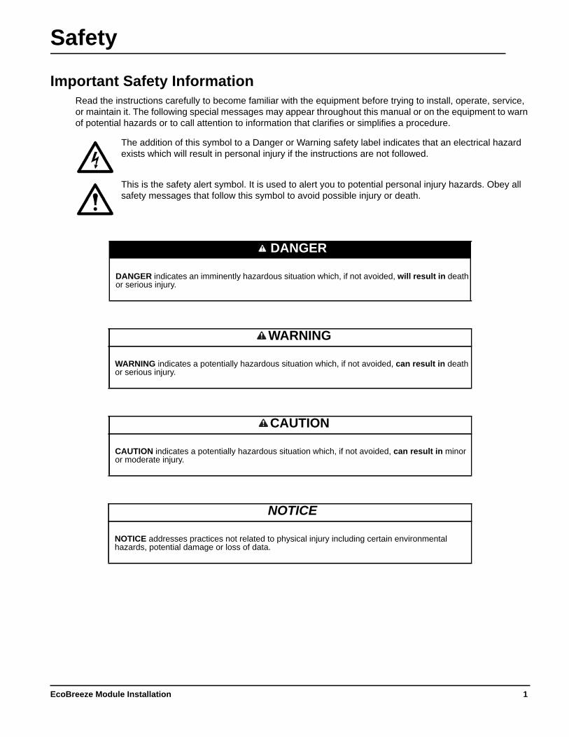
Important Safety InformationRead the instructions carefully to become familiar with the equipment before trying to install, operate, service, or maintain it. The following special messages may appear throughout this manual or on the equipment to warn of potential hazards or to call attention to information that clarifies or simplifies a procedure.
The addition of this symbol to a Danger or Warning safety label indicates that an electrical hazard exists which will result in personal injury if the instructions are not followed.
This is the safety alert symbol. It is used to alert you to potential personal injury hazards. Obey all safety messages that follow this symbol to avoid possible injury or death.
DANGER
DANGER indicates an imminently hazardous situation which, if not avoided, will result in death or serious injury.
WARNING
WARNING indicates a potentially hazardous situation which, if not avoided, can result in death or serious injury.
CAUTION
CAUTION indicates a potentially hazardous situation which, if not avoided, can result in minor or moderate injury.
NOTICE
NOTICE addresses practices not related to physical injury including certain environmental hazards, potential damage or loss of data.
1EcoBreeze Module Installation

Safety During InstallationRead and adhere to the following important safety considerations when working with this cooling unit.
DANGERHAZARD OF ELECTRIC SHOCK, EXPLOSION, OR ARC FLASH
Turn off all power supplying this equipment before working on the equipment. All electrical work must be performed by licensed electricians. Practice Lockout/Tagout procedures. Do not wear jewelry when working with electrical equipment.
Failure to follow these instructions will result in death or serious injury.
WARNINGHAZARD FROM MOVING PARTS
Keep hands, clothing, and jewelry away from moving parts. Check the equipment for foreign objects before closing the doors and starting the equipment.
Failure to follow these instructions can result in death, serious injury, or equipment damage.
NOTICEDAMAGE TO EQUIPMENT
To prevent condensation/ice in the system,
• The recommended minimum load for a Module is 10 kW during extremely cold ambient temperatures.• It is recommended to maintain the data center RH levels within the limits established by ASHRAE TC9.9.• Do not allow direct humidification into the return air duct of the EcoBreeze system.• If a Module is going to be turned off in a working Frame, do not isolate the Module.
Failure to follow these instructions can result in equipment damage.
EcoBreeze Module Installation2
General Information
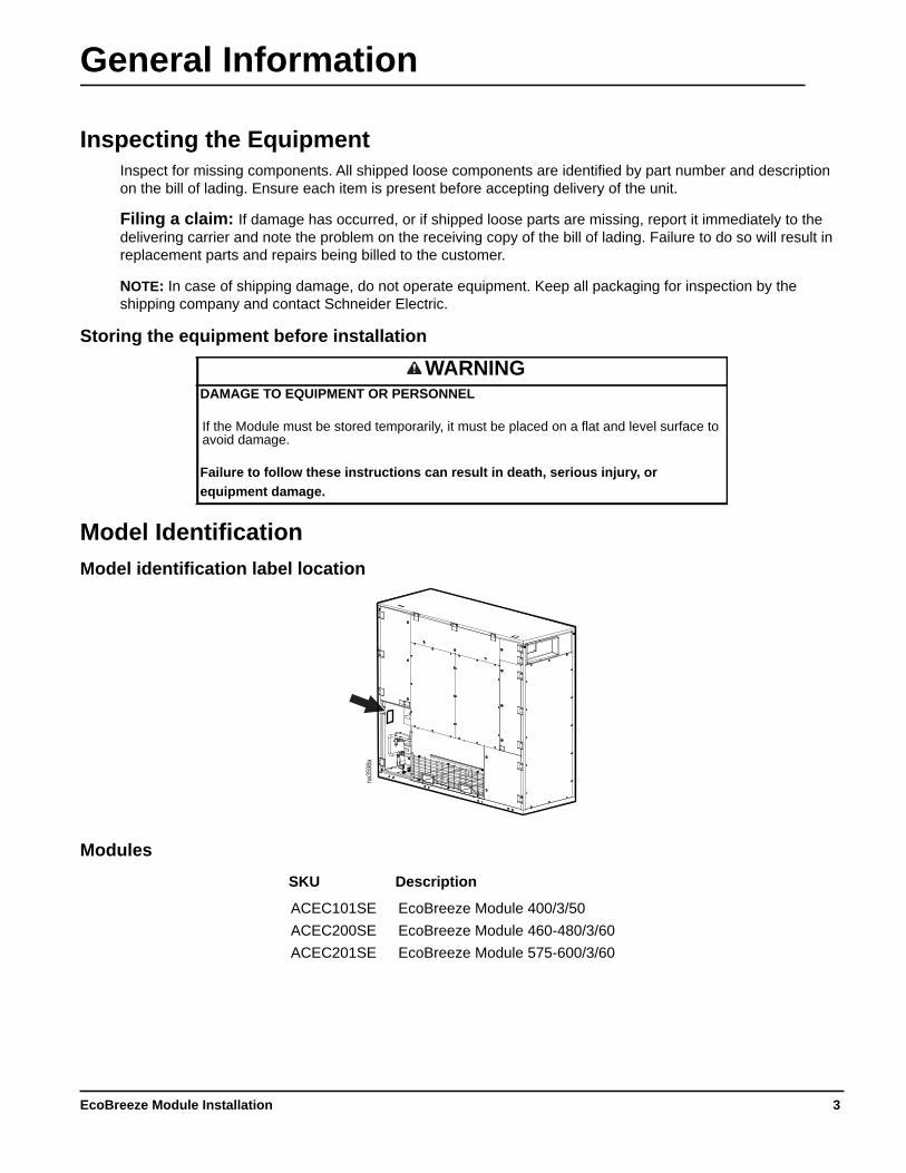
Inspecting the Equipment Inspect for missing components. All shipped loose components are identified by part number and description on the bill of lading. Ensure each item is present before accepting delivery of the unit.
Filing a claim: If damage has occurred, or if shipped loose parts are missing, report it immediately to the delivering carrier and note the problem on the receiving copy of the bill of lading. Failure to do so will result in replacement parts and repairs being billed to the customer.
NOTE: In case of shipping damage, do not operate equipment. Keep all packaging for inspection by the shipping company and contact Schneider Electric.
Storing the equipment before installation
Model IdentificationModel identification label location
Modules
WARNINGDAMAGE TO EQUIPMENT OR PERSONNEL
If the Module must be stored temporarily, it must be placed on a flat and level surface to avoid damage.
Failure to follow these instructions can result in death, serious injury, or equipment damage.
SKU Description
ACEC101SE EcoBreeze Module 400/3/50ACEC200SE EcoBreeze Module 460-480/3/60ACEC201SE EcoBreeze Module 575-600/3/60
na35
98a
3EcoBreeze Module Installation

Weights and DimensionsModule
Module Weight
ACEC101SE, ACEC200SE, ACEC201SE 1248 kg (2,750 lb)
na34
46a
1046 (41.20)
2489 (98)
2836 (111.64)
* Dimensions are shown in millimeters, with inches in parentheses.
EcoBreeze Module Installation4

Access Door OperationModule access doors and panels have latches that open with a Module access door latch tool.
DANGERHAZARD OF ELECTRIC SHOCK.
To avoid possible personal injury or death, the access door locking mechanism must be re-engaged after access to a compartment for inspection or service requirements.
Failure to follow these instructions will result in death or serious injury.
na34
63a
5EcoBreeze Module Installation

Component Identification
Inventory
Item Description Quantity
EcoBreeze Module assembly 1 Ship-loose kit (in drop-down box compartment) 1 Module access door latch tool (tie wrapped to OA fan grille) 2
na34
68a
SUPPLY
BLOWER
ACCESS
COIL
ACCESS
EcoBreeze Module Installation6
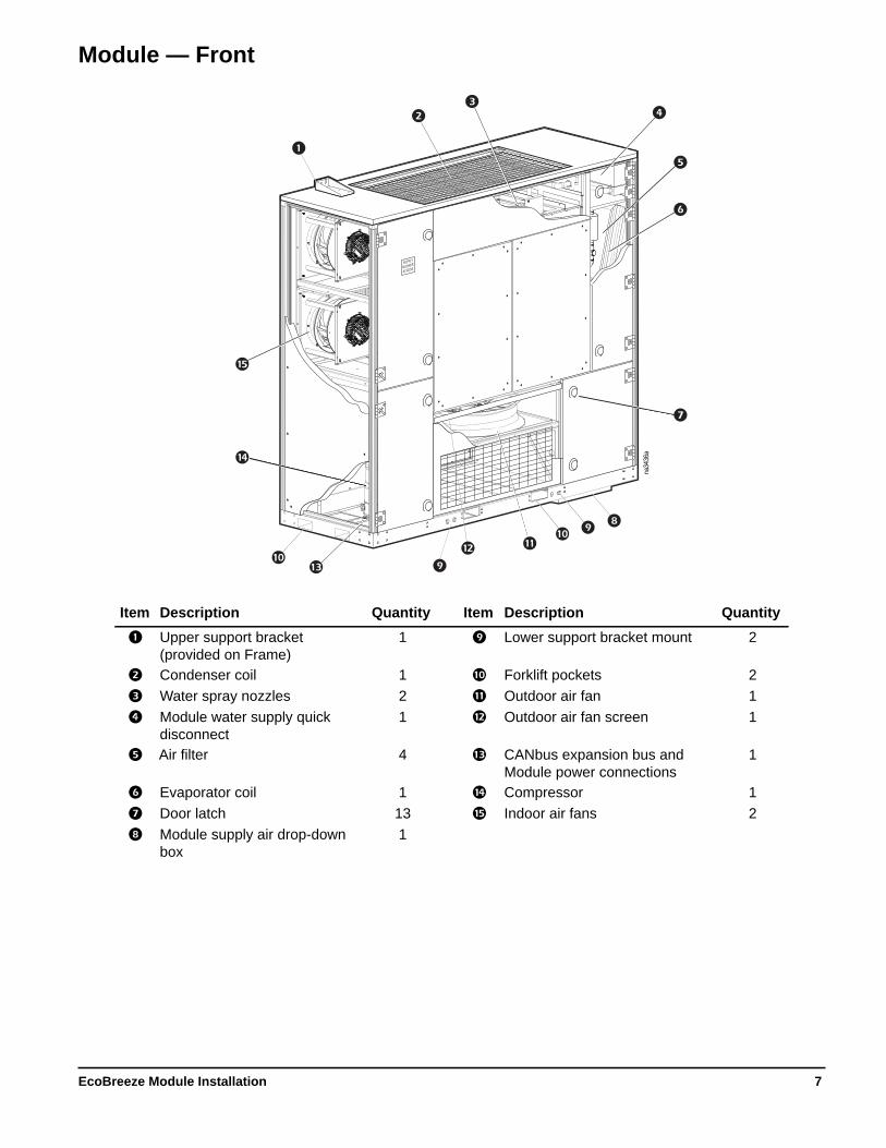
Module — Front
Item Description Quantity Item Description Quantity
Upper support bracket (provided on Frame)
1 Lower support bracket mount 2
Condenser coil 1 Forklift pockets 2 Water spray nozzles 2 Outdoor air fan 1 Module water supply quick
disconnect1 Outdoor air fan screen 1
Air filter 4 CANbus expansion bus and Module power connections
1
Evaporator coil 1 Compressor 1 Door latch 13 Indoor air fans 2 Module supply air drop-down
box1
SUPPLY
BLOWER
ACCESS
na34
36a
7EcoBreeze Module Installation

Module — Rear
Item Description
Indoor air fans DX coil condensate drain line
NOTE: Make sure the drain line is not blocked. Water collector Module water supply connector
na34
42a
EcoBreeze Module Installation8

Prepare for Installation
Lifting and Moving
The recommended tools for lifting and moving the equipment includes the following:
Unwrap the Module
See EcoBreeze Module Unpacking Sheet for more information on unpacking the Module.
WARNINGDAMAGE TO EQUIPMENT OR PERSONNEL
• Before lifting the EcoBreeze Module, ensure the lifting equipment is adequately sized for the load.
• Lift the EcoBreeze Module only from the provided forklift pockets.
• Check for overhead obstructions such as power cables.
• Maintain a minimum safe distance while equipment is lifted.
• Control access of personnel at lift site.
• There are no attachment points provided at the top of the EcoBreeze Module. Attempts to lift the Module from any point other than the provided forklift pockets may result in damage to the equipment.
Failure to follow these instructions can result in death, serious injury, or equipment damage.
NOTICEDAMAGE TO EQUIPMENT
Do not install the equipment during rain, snow, or other inclement weather.
Failure to follow these instructions can result in equipment damage.
Fork lift Rolling hydraulic dolly
Screw jack assembly (ACECSJ100SE)
(Optional)
NOTICEDAMAGE TO EQUIPMENT
When removing protective plastic wrap be careful to cut only the plastic and not damage the exterior of the equipment.
Failure to follow these instructions can result in equipment damage.
9EcoBreeze Module Installation
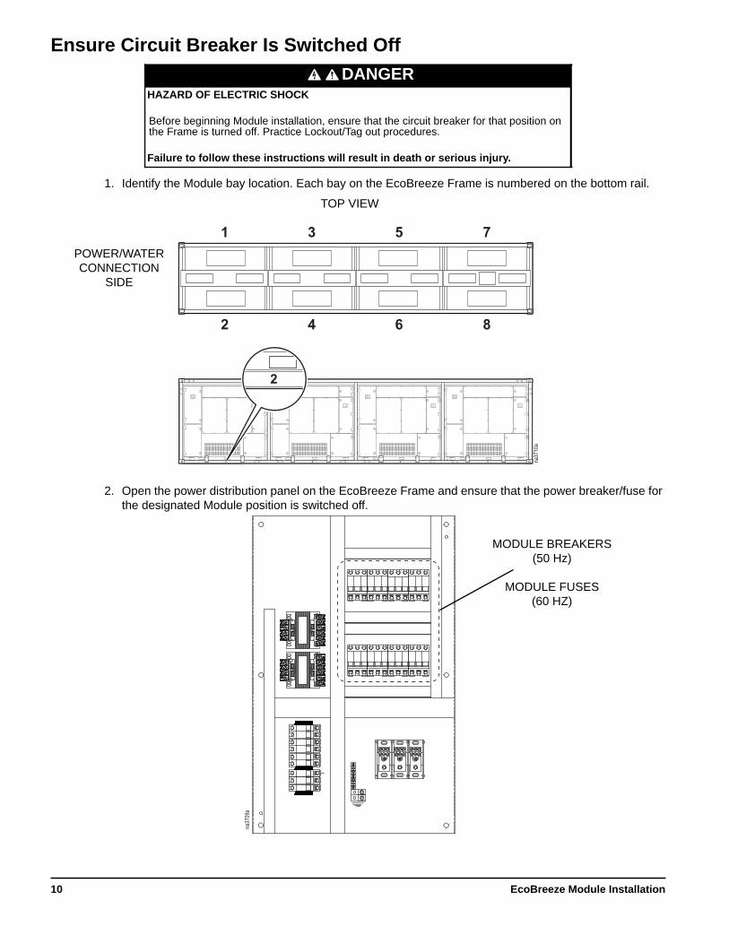
Ensure Circuit Breaker Is Switched Off
1. Identify the Module bay location. Each bay on the EcoBreeze Frame is numbered on the bottom rail.
2. Open the power distribution panel on the EcoBreeze Frame and ensure that the power breaker/fuse for the designated Module position is switched off.
DANGERHAZARD OF ELECTRIC SHOCK
Before beginning Module installation, ensure that the circuit breaker for that position on the Frame is turned off. Practice Lockout/Tag out procedures.
Failure to follow these instructions will result in death or serious injury.
1
2
3
4
5
6
7
8
na37
10a
SUPPLYBLOWERACCESS
COILACCESS
EQUIPMENT OPERATION HAZARD
Before removing this module: • Disconnect the power cable. • Disconnect the communication cable. • Remove top mounting bracket. • Removed the supply air transition damper. • Disconnect the Module water supply.
Failure to follow these instructions can result in equipment damage.
CAUTIONEQUIPMENT OPERATION HAZARD
Before removing this module: • Disconnect the power cable. • Disconnect the communication cable. • Remove top mounting bracket. • Removed the supply air transition damper. • Disconnect the Module water supply.
Failure to follow these instructions can result in equipment damage.
CAUTION
2 4 6 8
2
TOP VIEW
POWER/WATER CONNECTION
SIDE
na37
09a
MODULE BREAKERS (50 Hz)
MODULE FUSES (60 HZ)
EcoBreeze Module Installation10
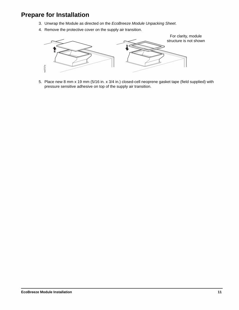
Prepare for Installation3. Unwrap the Module as directed on the EcoBreeze Module Unpacking Sheet.4. Remove the protective cover on the supply air transition.
5. Place new 8 mm x 19 mm (5/16 in. x 3/4 in.) closed-cell neoprene gasket tape (field supplied) with pressure sensitive adhesive on top of the supply air transition.
na37
27a
For clarity, module structure is not shown
11EcoBreeze Module Installation

Prepare the Frame6. Remove the shipping support bracket and Module support brackets from the Frame.
NOTE: Keep the Module support brackets to re-install after the Module is inserted into the Frame.
7. Remove the indoor fan bay cover and water trough cover.
na51
58a
SHIPPING SUPPORT BRACKET
MODULE SUPPORT BRACKET
MODULE SUPPORT BRACKET
na51
59a
INDOOR FAN BAY COVER
WATER TROUGH COVER
EcoBreeze Module Installation12
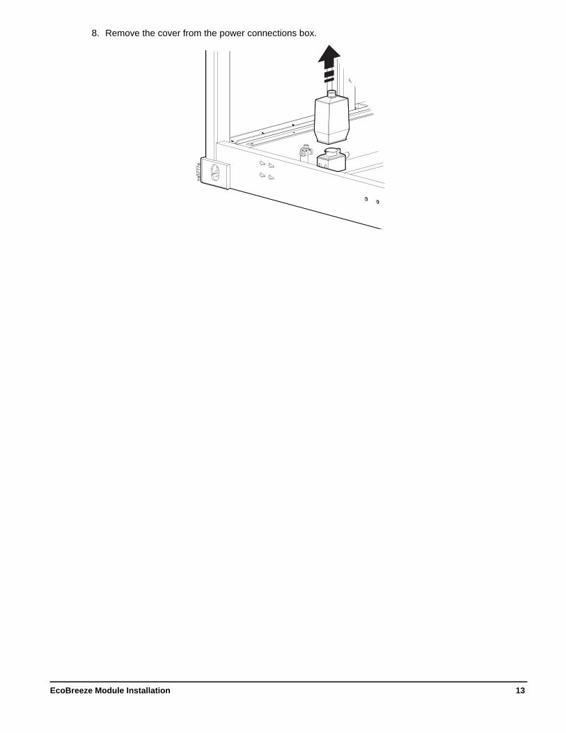
8. Remove the cover from the power connections box.
na57
77a
13EcoBreeze Module Installation
Install the Module
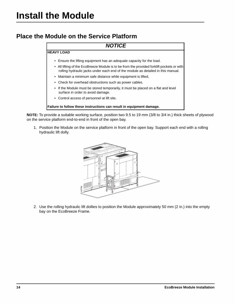
Place the Module on the Service Platform
NOTE: To provide a suitable working surface, position two 9.5 to 19 mm (3/8 to 3/4 in.) thick sheets of plywood on the service platform end-to-end in front of the open bay.
1. Position the Module on the service platform in front of the open bay. Support each end with a rolling hydraulic lift dolly.
2. Use the rolling hydraulic lift dollies to position the Module approximately 50 mm (2 in.) into the empty bay on the EcoBreeze Frame.
NOTICEHEAVY LOAD
• Ensure the lifting equipment has an adequate capacity for the load.
• All lifting of the EcoBreeze Module is to be from the provided forklift pockets or with rolling hydraulic jacks under each end of the module as detailed in this manual.
• Maintain a minimum safe distance while equipment is lifted.
• Check for overhead obstructions such as power cables.
• If the Module must be stored temporarily, it must be placed on a flat and level surface in order to avoid damage.
• Control access of personnel at lift site.
Failure to follow these instructions can result in equipment damage.
COIL
ACCESS
SUPPLY
BLOWER
ACCESS
COIL
ACCESS
ns37
30a
EcoBreeze Module Installation14

Install the Module Screw Jack1. Attach the lower screw jack bracket to the keyhole openings on the bottom rail of the EcoBreeze Frame
at each end of the desired Module bay on the Frame.
2. Using the coupling sleeves, install the transmission shaft .
3. Adjust the wheel height to level the screw shaft. a. Place a 2 x 4 piece of wood in the
doorway of the Module frame of the
KEYHOLE SLOT FRAME RAILSCREW JACK
COUPLING SLEEVECOUPLING SHAFT
na56
71a
2 x 4 PIECE OF WOOD
15EcoBreeze Module Installation

compressor compartment and in the doorway of the drop-down box access door to prevent damage to the frame or the screw jack.
b. Attach each screw jack upper bracket to the Module using two bolts.c. Adjust the height of the wheels on the screw jack casters so the wheels are placed firmly against
the service platform. Securely tighten all fasteners.d. Install two #10 wood screws on
the bottom of the screw jack transmission bracket to secure it to the plywood.NOTE: Secure the plywood to the platform.
e. Use the adjustment slots on the screw jack transmission bracket to level the screw shaft.
4. To ease Module installation, place a hydraulic jack underneath the Module to help support the weight of the Module.
5. Attach a cordless power drill with a 1/2-in. jaw opening to the drive stud on the transmission on either end of the screw jack.NOTE: It is recommended to go slowly to avoid damaging the Module or screw jack assembly.
ns37
37a
na56
73a
EcoBreeze Module Installation16

Position the Module Into the Frame1. Ensure that the back of the Module is supported by the Frame and the front of the Module is supported
by the screw jack. 2. Remove the rolling hydraulic lift dollies.
1. Operate the screw jack to push the Module the rest of the way into the bay on the EcoBreeze Frame. 2. Remove the two bolts attaching the screw jack to the Module and the two wood screws holding the
screw jack transmission bracket to the plywood. Remove the screw jack from the keyhole openings on the bottom rail of the Frame.
3. Attach the upper and lower Module anchor brackets.
4. Open the upper right access door and remove the water connection cover to connect the Module water supply line.
5. Replace the water connection cover.
CAUTIONHEAVY EQUIPMENT
With the rolling hydraulic lifts removed, the weight of the Module is supported by the Frame at the back and the screw jack wheels at the front. Before removing the lifts, confirm that the weight of the Module will be properly supported.
Failure to follow these instructions can result in injury and equipment damage.
SUPPLY
BLOWER
ACCESS
COIL
ACCESS
UPPER MODULE ANCHOR BRACKET
LOWER MODULE ANCHOR
BRACKETS
SUPPLY
BLOWER
ACCESS
na37
84a
17EcoBreeze Module Installation

Lower the Drop-Down Box 1. Open the lower-right door on each Module being installed.2. For shipping, the drop-down box is secured upside down inside the Module. Remove the screws
securing the drop-down box (a).NOTE: The screws will be re-used to install the drop-down box along with screws in the ship-loose kit.
3. Turn the drop-down box over (b) so it faces right-side up (c).
4. Apply caulking around the opening in the bottom of the Module and insert the drop-down box through the opening in the bottom of the Module and attach it to the Module with the supplied screws (a).
5. Line up the drop-down box with the supply air transition and attach it to the supply air transition (b).NOTE: The drop-down box is flexible enough to adjust for slight misalignments.NOTE: Hardware to attach the drop-down box to the supply air transition is field supplied.
6. Locate the insulation strips packed in the ship-loose kit.7. Remove the backing from the insulation and apply the insulation around the air transition ducts.8. Open the damper on the supply air transition.
na44
50a
SUPPLY
BLOWER
ACCESS
COIL
ACCESS
SUPPLY
BLOWER
ACCESS
COIL
ACCESS
SUPPLY
BLOWER
ACCESS
COIL
ACCESS
SUPPLY
BLOWER
ACCESS
COIL
ACCESS
na44
53aSUPPLY AIR
TRANSITION
MODULE DROP-DOWN BOX
FOR CLARITY, MODULE STRUCTURE
IS NOT SHOWNMODULE
EcoBreeze Module Installation18
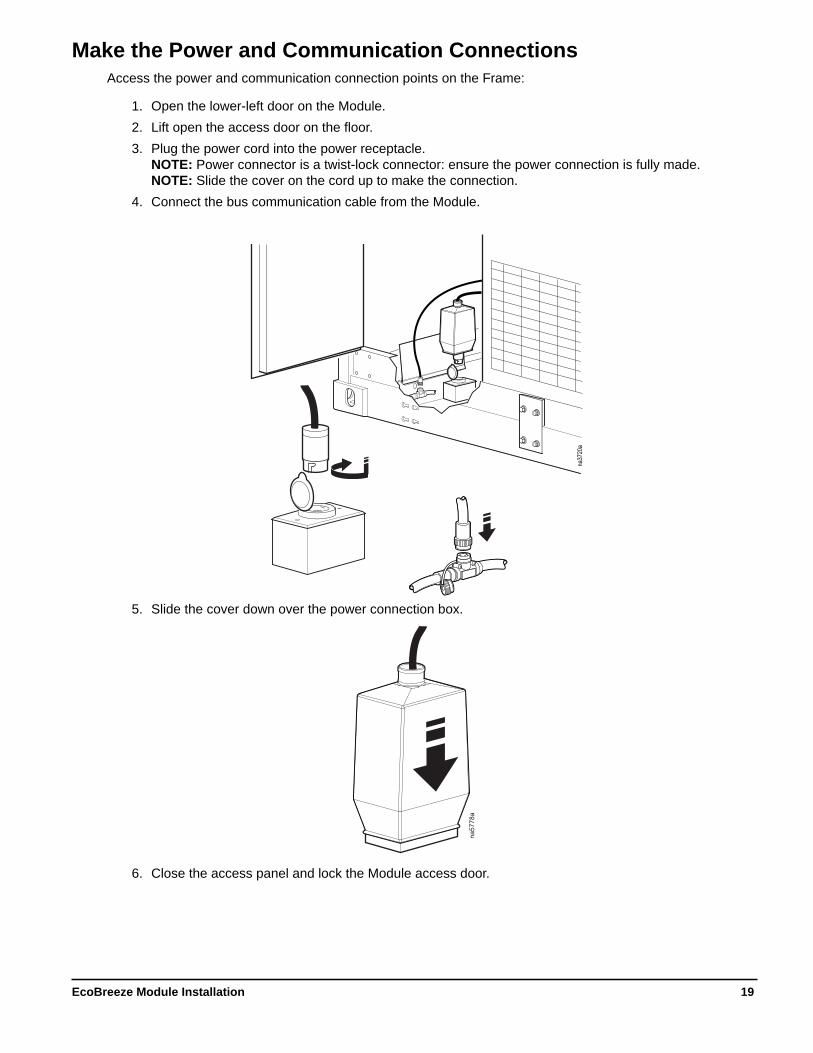
Make the Power and Communication ConnectionsAccess the power and communication connection points on the Frame:
1. Open the lower-left door on the Module.2. Lift open the access door on the floor.3. Plug the power cord into the power receptacle.
NOTE: Power connector is a twist-lock connector: ensure the power connection is fully made.NOTE: Slide the cover on the cord up to make the connection.
4. Connect the bus communication cable from the Module.
5. Slide the cover down over the power connection box.
6. Close the access panel and lock the Module access door.
na37
20a
na57
78a
19EcoBreeze Module Installation

Prepare Module for StartupTurn the handle on the return air transition to open the return air damper.
Refer to the EcoBreeze Operation & Maintenance manual for the Module startup procedures.
Set the Module IDIMPORTANT: Only power on one Module at a time when setting Module IDs. If multiple Modules are powered on without Module IDs being set, there will be a communication conflict that will prevent Module IDs from being properly set. After the Module ID for a Module is set, that Module can remain powered on during the rest of the setup process.
1. Turn of circuit breaker/fuse disconnect for the Module being installed.2. Turn on circuit breakers 1CB, 2CB, and compressor motor starter protector 1COMPMSP in the
electrical panel of the Module.3. Verify that power has been applied to the Module by ensuring the Module components are on.
NOTE: The Module controller will have LEDS illuminated.4. Verify that the DIP switches on the Module controller are set correctly:
1 = UP/OFF
na35
55a
OPEN
CLOSED
1
2
3
4
5
6
7
8 na
3710
a
SUPPLYBLOWERACCESS
COILACCESS
EQUIPMENT OPERATION HAZARD
Before removing this module: • Disconnect the power cable. • Disconnect the communication cable. • Remove top mounting bracket. • Removed the supply air transition damper. • Disconnect the Module water supply.
Failure to follow these instructions can result in equipment damage.
CAUTIONEQUIPMENT OPERATION HAZARD
Before removing this module: • Disconnect the power cable. • Disconnect the communication cable. • Remove top mounting bracket. • Removed the supply air transition damper. • Disconnect the Module water supply.
Failure to follow these instructions can result in equipment damage.
CAUTION
2 4 6 8
2
TOP VIEW
POWER/WATER CONNECTION
SIDE
MODULE ID NUMBERS
EcoBreeze Module Installation20

2 = DOWN/ON3 = DOWN/ON4 = DOWN/ON5 - UP/OFF
5. Make sure the remote display and I/O Module have up-to-date firmware.
See the Service Manual for instructions on updating firmware.
6. Enter Diagnostics mode.7. Select Set Module ID.8. Enter Level (4) password “-12”.9. Select Module 0.
NOTE: When a Module is first powered on, its ID is set to ‘0’.10.Change the Module ID to the correct ID based on the Module location in the Frame.11. Repeat this section for each new Module.12.After all Module IDs are set, press ESC to exit Diagnostics.
21EcoBreeze Module Installation

Remove a Module From the Frame1. Disconnect the power and communication cables located in the compressor compartment.
2. Disconnect the water supply.
3. Remove the drop-down box in the lower-right compartment.
na37
20b
SUPPLY
BLOWER
ACCESS
na37
84b
na44
50b
SUPPLY
BLOWER
ACCESS
COIL
ACCESS
SUPPLY
BLOWER
ACCESS
COIL
ACCESS
SUPPLY
BLOWER
ACCESS
COIL
ACCESS
SUPPLY
BLOWER
ACCESS
COIL
ACCESS
EcoBreeze Module Installation22

4. Remove the upper and lower Module anchor brackets.
5. Attach the lower screw jack bracket to the keyhole openings on the bottom rail of the EcoBreeze Frame at each end of the desired Module bay on the Frame.
6. Using the coupling sleeves, install the transmission shaft .
7. Adjust the wheel height to level the screw shaft.
na45
01a
KEYHOLE SLOT FRAME RAILSCREW JACK
na56
72a
COUPLING SLEEVECOUPLING SHAFT
23EcoBreeze Module Installation

a. Place a 2 x 4 piece of wood behind the Module frame of the compressor compartment and in the doorway of the drop-down box access door to prevent damage to the frame or the screw jack.
b. Attach each screw jack upper bracket to the Module using two bolts.
c. Adjust the height of the wheels on the screw jack casters so the wheels are placed firmly against the service platform. Securely tighten all fasteners.
d. Install two #10 wood screws on the bottom of the screw jack transmission bracket to secure it to the plywood.NOTE: Attach plywood to the platform.
e. Use the adjustment slots on the screw jack transmission bracket to level the screw shaft.
8. Attach a cordless power drill with a 1/2-in. jaw opening to the drive stud on the transmission on either end of the screw jack.NOTE: It is recommended to go slowly to avoid damaging the Module or screw jack assembly.
9. Operate the screw jack to remove the Module from the Frame.
10.To ease Module removal, after the Module is about 1/3 out of the Frame, place a hydraulic jack underneath the Module to help support the weight while the rest of the Module is removed.
11. Use hydraulic dollies to move the Module to a location where a forklift can be used to transport the Module.
na56
71a
2 x 4 PIECE OF WOOD
ns37
37b
na56
73a
EcoBreeze Module Installation24


Worldwide Customer SupportCustomer support for this or any other product is available at no charge in any of the following ways:
• Visit the Schneider Electric Web site to access documents in the Schneider Electric Knowledge Base and to submit customer support requests.– www.schneider-electric.com (Corporate Headquarters)
Connect to localized Schneider Electric Web sites for specific countries, each of which provides customer support information.
– www.schneider-electric.com/support/Global support searching Schneider Electric Knowledge Base and using e-support.
• Contact the Schneider Electric Customer Support Center by telephone or e-mail.– Local, country-specific centers: go to www.schneider-electric.com > Support > Operations
around the world for contact information.
For information on how to obtain local customer support, contact the representative or other distributors from whom you purchased your product.
As standards, specifications, and designs change from time to time, please ask for confirmation of the information given in this publication.© 2015 Schneider Electric. All Rights Reserved.The Schneider Electric logo is a trademark owned by Schneider Electric Industries S.A.S., or its affiliated companies. All other trademarks are the property of their respective owners.
10/2015990-5221C-001