INSTALLATION, HANDLING, OPERATION, … REV K.pdf · INSTALLATION, HANDLING, OPERATION,...
19
INSTALLATION, HANDLING, OPERATION, TROUBLESHOOTING, MAINTENANCE of the Model HTP and Model HTX Claus Thermal Reaction Furnace Thermocouple Model Number: _____ - - - - - - Serial Number(s): Type Thermocouple Elements: Operating: Reference: Dryout: Supplied with this thermocouple: Refractory Well: Yes No Refractory Drilling Kit: Yes No Nozzle Packing: Yes No Refractory Stops Yes No Purge Gas Panel: Yes No Refractory Mandrel: Yes No Extension Lead wire Yes No Horizontal Mounting Bars Yes No Refractory Drill Motor Yes No Customer: Purchase Order No: Tag Number(s): Other: This thermocouple was designed to be installed on a reactor vessel with the following dimensions: A B C R F D W A: Nozzle Inside Diameter B: Connection Size and Class C: Shell Thickness D: Nozzle Height W: Refractory Well R: Refractory Thickness F: Element Well Insertion Length The hole through the refractory must be 2.2” + 0.2” – 0.0”( 55 mm + 5 mm – 0 mm) Doc 00-HTP03 Rev K1
Transcript of INSTALLATION, HANDLING, OPERATION, … REV K.pdf · INSTALLATION, HANDLING, OPERATION,...

INSTALLATION, HANDLING, OPERATION, TROUBLESHOOTING, MAINTENANCE
of the Model HTP and Model HTX
Claus Thermal Reaction Furnace Thermocouple
Model Number: _____ - - - - - - Serial Number(s): Type Thermocouple Elements: Operating: Reference: Dryout:
Supplied with this thermocouple: Refractory Well: Yes No Refractory Drilling Kit: Yes No Nozzle Packing: Yes No Refractory Stops Yes No Purge Gas Panel: Yes No Refractory Mandrel: Yes No Extension Lead wire Yes No Horizontal Mounting Bars Yes No Refractory Drill Motor Yes No Customer: Purchase Order No: Tag Number(s): Other: This thermocouple was designed to be installed on a reactor vessel with the following dimensions:
A B
C
R
F D
W
A: Nozzle Inside Diameter B: Connection Size and Class C: Shell Thickness
D: Nozzle Height
W: Refractory Well
R: Refractory Thickness
F: Element Well Insertion Length The hole through the refractory must be
2.2” + 0.2” – 0.0”( 55 mm + 5 mm – 0 mm)
Doc 00-HTP03 Rev K1


Table of Contents
Resolving Dimensional Problems. .................................................................................................... 6
Shipping Preparation, Storage & Handling 3 Transport ............................................................................................................................................. 3
Storage ................................................................................................................................................ 3
Handling .............................................................................................................................................. 3
Pre-Installation Preparation 3 Survey the Installation ......................................................................................................................... 3
Inspect the Thermocouple and Accessories ........................................................................................ 3
Inspect the Nozzle ............................................................................................................................... 5
Installing the Thermocouple 7 Vertical Installation .............................................................................................................................. 7
Non-Vertical Installation ..................................................................................................................... 10
Non-Vertical Installation - Using the HMB Mounting Bars .................................................................. 11
Wiring ................................................................................................................................................ 12
Purge Gas Connection ...................................................................................................................... 13
Purge/Element Well Integrity Test ...................................................................................................... 13
Technical Operation and Maintenance 14 Pre-Commissioning/Commissioning Procedure (Startup) .................................................................. 14
Shutdown .......................................................................................................................................... 14
Operation ........................................................................................................................................... 14
Maintenance ...................................................................................................................................... 14
Troubleshooting ................................................................................................................................. 14
Specifications 15 Dimensions ........................................................................................................................................ 16

2 | P a g e
A brief video presentation of the steps of the complete HTP/HTX installation may be found at www.claustemp.com/00-htp01.htm#Installation.
INSTALLATION GUIDE
Components of the HTP/HTX Claus Thermal Reactor Thermocouple System Referenced in this Manual
The following listed components are required for proper installation of the HTP/HTX. Failure to utilize these Components will reduce the life of the HTP/HTX and cause possible failure.
Model Description Notes
HTP HTX
Claus Thermal Reaction Furnace
Thermocouple
Thermocouple assembly with mounting flange, Body, purge connections, terminal enclosure housing and element well. Models HTP and HTX are identical in operation, installation, and performance. Slight differences in dimensions are shown at the end of this manual.
HRW
Refractory Well The large refractory well collar rests in the refractory and protects the element well
HNP
Nozzle Insulation Kit
Woven and Pressed Disks for proper insulation of the nozzle, also protection against nozzle overheating, buildup of sulfur in the nozzle, and for physical protection of the inner element well
HFS
Flush Gas Control Panel
(usually shipped separately)
Includes flow indicator, flow control valve, pressure regulator, filter, dripwell, and gage on stainless steel panel with mounting hardware.
HMB
Horizontal Mounting Bars
(usually shipped separately)
Assists installation in non-vertical nozzles.
HTP HTX

3 | P a g e
Shipping Preparation, Storage & Handling
Transport
Care should be used in carrying, moving, and shipping the HTP/HTX thermocouple. A significant portion of the HTP/HTX is constructed of ceramic. Ceramics are very brittle at ambient temperature and can be damaged by mechanical shock. The unit is equipped with a sand-filled protective shipping tube when it leaves the factory. This tube and its sand packing should be left in place until the persons installing the unit have arrived at the installation site and are ready to insert the HTP/HTX and make up the flange. The shipping tube and shipping crate should be retained for re-shipment and storage of the HTP/HTX assembly.
Storage
Store equipment in a clean, dry place. It is recommended that the equipment remain packaged until ready for installation to prevent breakage or misplacing of components. When storing a unit or preparing it for shipment, the shipping tube should be reinstalled and filled with clean, fine #1 blasting sand.
Handling
Unit(s) are constructed with ceramic material that is susceptible to damage from rough handling. Unit(s) should only be handled with their protective shipping pipes in place, and, whenever possible transported to/from the installation site in their original shipping containers.
Pre-Installation Preparation A video of the installation process is available at http://www.youtube.com/watch?v=r2WmrERLEaQ
You can view the video on a smartphone by scanning the QR code shown here.
Survey the Installation a. Confirm the vessel nozzle location relative to the instrument tag
number, the planned installation location of the Delta Controls Purge Control Panel and the temperature transmitter. (Note: Because most plants have standardized on a specific thermocouple transmitter manufacturer, the thermocouple transmitter is not supplied by Delta Controls.)
b. Confirm the transmitter thermocouple compatibility with the thermocouple element type(s). c. Confirm the availability of the proper type thermocouple extension leadwire for connection of
the transmitter. A separate cable is required for each thermocouple element. The type cable is determined by the type(s) of elements in the thermocouple assembly as noted on the cover of this document. Note: Thermocouple extension leadwire may be obtained from Delta Controls stock at nominal cost.
d. Secure the flange bolts, studs and required flange gasket.
Inspect the Thermocouple and Accessories
a. Open the carton and carefully remove the top layer of the packing materials.

4 | P a g e
b. Visually inspect the HTP/HTX Assembly for damage. c. Visually inspect the large ceramic HRW Refractory Well for damage. Be very careful not to
drop the well as it can be easily broken. d. The protective steel pipe attached to the flange surrounds the ceramic element well. This pipe
is filled with sand to support and protect the element well during shipping. Carefully remove the thermocouple from the carton, move it to an area where the sand can be safely emptied. Using the safety knife provided (or a very small pocket knife, but not a screwdriver) carefully cut the tape from the end of the steel protective shipping pipe. Turn the thermocouple upright to pour out the sand into a container.
e. Insert the tip of a large screwdriver or similar robust tool into the lug welded to the protective pipe and using it as a lever, twist the pipe to loosen it to permit easy removal by hand at the installation site. Occasionally, this may require the use of a pipe wrench. Loosen the pipe, but leave the pipe in place until the thermocouple is to be inserted into the vessel nozzle.
f. Inspect inside the end of the pipe and gently touch the tip of the element well to be certain that it is not “loose”. If loose, the thermocouple is broken and must be repaired prior to installation. The shipping pipe and the custom built protective shipping carton are reusable and may be saved for reshipment or storage of the HTP/HTX assembly.
g. If any parts appear to be damaged, contact Delta Controls immediately.
Sand-Filled Steel Protective Shipping Pipe
HTX Thermocouple shown
2. After removing the sand, loosen, but do not remove, the protective shipping pipe. This permits easy removal at the time of installation.
1. Carefully cut open the tape at the end of the shipping tube. Do not use a screwdriver. Pour out the sand.

5 | P a g e
Inspect the Nozzle
Because the “As-Built” dimensions of the refractory and nozzle can (and often do) differ from the design specifications, it is important to verify these dimensions before installing the thermocouple. Installing a thermocouple that is not properly sized for the nozzle and refractory can result in breakage or inaccurate measurements.
Inspect the inside of the vessel nozzle. The inside of the nozzle should be clean and free from debris and welding slag. The hole cut through the vessel shell at the base of the nozzle should be a minimum 3-1/2” (90 mm) diameter. The top refractory surface should be even and free from extensive damage. The bored hole through the refractory should be clean, 2.2” to 2.4” (50-56mm) diameter, centered in the nozzle and in perpendicular alignment relative to the nozzle flange face. If the hole does not meet the above criteria, the thermocouple can become broken shortly after start up as refractory begins to shift. Check the nozzle and refractory dimensions. (Refer to the drawing on the cover of this document)
To ascertain Dimension “F”, lay a straight edge across the flange face and with a measuring tape, hook the inside surface (hot face) of the refractory inside the vessel and measure up to the straight edge. Confirm this dimension is the same as the length of the thermocouple element well as measured from the thermocouple flange to the tip of the well.
(If the thermocouple element well is too long, it will contact the refractory well when it is inserted, causing it to become broken. If the thermocouple is too short, it may read erroneously low.
Measure the Refractory Thickness with a measuring tape. Confirm that this distance matches the length of the straight portion of the HRW Refractory Well as shown. (If the HRW well is too short, the thermocouple will contact it during thermocouple insertion, causing it to break. If the HRW well is too long, there is an increased possibility of breakage due to thermal shock)
If there is a discrepancy of more than ½” (12 mm) on the above measurements, DO NOT install the thermocouple until the discrepancy is resolved. (see below)
HRW Refractory Well
Refractory Thickness
Refractory Thickness
Insertion Length ”F”
HTX Thermocouple
shown
Insertion Length ”F”
Note: The HRW Refractory Well is intended to protrude approximately 1” (25 mm) beyond the
refractory hot face

6 | P a g e
Resolving Dimensional Problems.
Carefully measure the nozzle and refractory dimensions and compare them to the dimensions on the front cover of this manual. Dimensional discrepancies are commonly caused by the following conditions:
1. Nozzle Inner Diameter is not as specified – If the nozzle I.D. is too small, the hard insulating rings will not fit. These rings can be cut down to size. This is best done in a lathe with a tapered arbor to fit the center hole. Use a dust collector when cutting these rings to avoid breathing the dust.
2. Nozzle height is not as specified – If the nozzle is too tall, the thermocouple will not extend all the way into the vessel and may report erroneously low temperatures. If the nozzle is too short, the thermocouple may contact the bottom of the refractory well causing it to break. (See Note “4”, below). Contact Delta Controls to arrange for a thermocouple correctly sized for the installation.
3. Incorrectly specified thermocouple dimensions – The design intent is for the thermocouple element tip to be positioned even with the refractory hot face, and for the HRW Refractory Well to extend approximately 1 inch (2.5 cm) past the refractory hot face. If these conditions are not met, the result may be inaccurate measurement and/or breakage due to mechanical interference or thermal shock. Contact Delta Controls to arrange for a thermocouple that is correctly sized for the installation.
4. Refractory has entered the base of the nozzle -. The top surface of the refractory should be even with the inside surface of the vessel shell. If it is not, the HRW Refractory Well will not rest at the proper position and may cause it to be broken when the thermocouple is inserted into the nozzle. If there is refractory material inside the base of the nozzle, it must be removed to restore a flat surface that is even with the inner surface of the vessel shell.
5. Refractory is not installed at the specified thickness – If the overall refractory is thicker than specified, the thermocouple will not extend all the way into the vessel and may report erroneously low temperatures. If the refractory is thinner than specified, the thermocouple will extend past the refractory hot face. This could increase the possibility of breakage due to thermal shock. Contact Delta Controls to arrange for a thermocouple that is correctly sized for the installation.
6. Refractory firebrick has separated from the insulating castable – It is not uncommon for the firebrick to sag and form a gap between the firebrick and the castable or insulating brick. Often, thermal expansion will cause this gap to close by itself when the furnace reaches operating temperature. If this is the only cause of dimensional discrepancy, thermocouple installation may proceed.
7. Refractory has separated from the vessel shell – This condition is not common, but it is possible for a gap to appear between the insulating refractory and the vessel shell. The result is that the thermocouple may not extend far enough into the vessel to reach the refractory hot face and may report erroneously low temperatures. In general, this gap will not close up at operating temperatures. The thermocouple must be re-sized to account for the gap. Contact Delta Controls to arrange for a thermocouple that is correctly sized for the installation.

7 | P a g e
Installing the Thermocouple
Vertical Installation (For non-vertical installations do steps 1-5, proceed to page 11.)
4. Place approximately 8 – 10 each of the soft compressible nozzle rings, with the ¾” (19 mm) center hole, in the bottom of the nozzle. Insure that the center holes are in alignment.
Compressible Nozzle Rings
Collar Rings
3. Place the two soft compressible collar rings from the HNP Nozzle Insulation Kit, having an I.D. of 2.75” (70 mm), around the refractory well collar. They should fill the gap between the outside of the refractory well collar and the inside of the vessel nozzle.
Collar Rings
F+1in.
Insertion Length,F
Element Well
Refractory Well
1. Carefully set HRW Refractory Well down onto the hole in the refractory. The collar of the HRW should rest flat against the refractory surface and the tip should extend about 1 inch (25 mm) beyond the refractory into the reactor vessel. The fit should be somewhat loose.
Model HRW Refractory Well
2. Double-check for proper clearance prior to thermocouple insertion by measuring from the bottom of the refractory well up to the flange face. The distance should be approximately 1 inch (25mm) longer than the insertion length of the element well (Dimension F on the front cover of this manual).

8 | P a g e
Note that the thermocouple is heavy and the ceramic element well may be easily broken. During the following steps, do not allow any sideways forces to be exerted on the ceramic parts.
8. Have an assistant lift the thermocouple and turn it to a vertical position. The installer then grasps the unit by the top housing, permitting the unit to hang vertically plumb. With no assistance, center the element well over the center hole in the top insulating ring and gently lower the unit into place on the flange.
Gasket
Model HTX Thermocouple
shown
7. Carefully remove the protective pipe from the thermocouple and place it in a safe location.
Steel Protective (Shipping) Pipe
Model HTX Thermocouple
shown
Gasket
6. Place and center the flange gasket on the vessel nozzle flange.
5. Place enough of the rigid pressed 1-1/2” (38 mm) thick rings into the nozzle so that the top half of the top ring extends above the flange. If needed, remove or insert additional lower soft rings to obtain this fit.
Rigid, Pressed Rings

9 | P a g e
After installation and before reactor startup, perform the Purge / Element Well Integrity Test on page 13. This will verify that the element well was not broken during installation, and that there are no problems with the purge connections. Performing this test as soon as possible prior to reactor startup will allow time to obtain replacements in the event of element well breakage. In general, replacement is not possible while the reactor is running. A thermocouple that has a broken element well or that is improperly purged will only operate for a short time before failing.
11. Install instrument conduit, wiring and purge gas tubing as described below.
10. Keeping the unit centered on the flange, gently rotate it to the desired position for electrical and purge connections. Install and tighten the flange studs.
9. The soft compressible nozzle rings will compress as the thermocouple is positioned into place.
Compressible Nozzle Rings

10 | P a g e
Non-Vertical Installation
In non-vertical installations, insertion of the thermocouple unit can be difficult. The installer must attempt to support the full weight of the thermocouple unit while fully inserting it into the centerline of the nozzle insulating materials at the appropriate angle without allowing the weight of the unit to impart side-loads on the element protective well. The Model HMB Thermocouple Mounting Guide Bars provide an easy and safe means of inserting the heavy thermocouple in non-vertical nozzles. The use of the Guide Bars minimizes the risk of breakage of the element protective well due to misalignment of the unit with the nozzle centerline as it is being inserted into position.
A video showing the use of the HMB mounting bars is available at http://www.youtube.com/watch?v=r2WmrERLEaQ You can view the video on a smartphone by scanning the QR code shown here.
This space intentionally left blank

11 | P a g e
Non-Vertical Installation - Using the HMB Mounting Bars 1. Install the HRW refractory well and nozzle insulation rings as described in steps 1-5 beginning on page 7.
9. Install the remaining studs and nuts. Assure the flange and gasket is centered; tighten all to specification.
10. Install instrument conduit, wiring and purge gas connections as below.
7. Loosely install studs and nuts in all empty holes to hold the thermocouple in place as the guide bars are removed.
Purge connections
6. Making sure the thermocouple unit is correctly rotated so that the purge and wiring connections are oriented in the desired direction; allow the mounting bars to support the weight of the thermocouple as it is carefully guided into position.
Thermocouple
Wiring connections
Stud with nut Flange Gasket
5. Place studs in 3 places as shown. Place the flange gasket in position. The studs will temporarily hold the flange gasket in position.
Mounting Bars
4. Similarly, install the other mounting bar on the opposite bolt hole.
Nozzle Flange
Nut This hole for 150# flanges
2. Insert an R-Clip into the appropriate hole near the threaded end of one of the mounting bars.
Nut
R-Clip
This hole for 300# flanges
8. Remove the mounting bar nuts. Using a large screwdriver or pliers, pull the R-clips and remove the mounting bars.
3. Place the threaded end of the mounting bar into a vessel nozzle flange bolt hole as shown. Secure the bar to the flange with the provided nut.

12 | P a g e
Wiring
• The conduit connecting to the terminal enclosure should be equipped with a union and a flexible conduit for ease of maintenance and to reduce strain on the terminal enclosure.
• Ensure that the insulation on thermocouple extension lead wire is rated for 400°F (200°C) continuous service.
• Installation shall comply with EN60079-14 and/or other governing codes. The thermocouple elements are terminated on the connecting blocks, which are mounted inside the thermocouple head. The block positions are marked “O”, “R”, and “D” to designate which thermocouple is connected at each set of two terminal points. The negative lead position is marked with a red dot on each set. The standard arrangement is:
O: The Operating thermocouple; usually a type “R”, “S” or “B” platinum/rhodium. R: The Reference thermocouple; same type as the operating thermocouple. D: The Dryout thermocouple; usually a type “T” or “K” (supplied as an option on some models)
Thermocouple Terminal Connections – Operating and Reference Thermocouples only, no Dryout
“O” Operating Pair
“R” Reference Pair
Terminal Enclosure (Cover removed)
+ -
“D” Dryout Pair “O” Operating Pair
“R” Reference Pair
+
_
Thermocouple Terminal Connections –Operating, Reference, and Dryout Thermocouples
Terminal Enclosure (Cover removed)
13 | P a g e
Pressure Regulator
Adjustment
Purge Pressure Indicator
Flow Indicator
Needle Flow Control Valve
MODEL HFS PURGE GAS PANEL (front view)
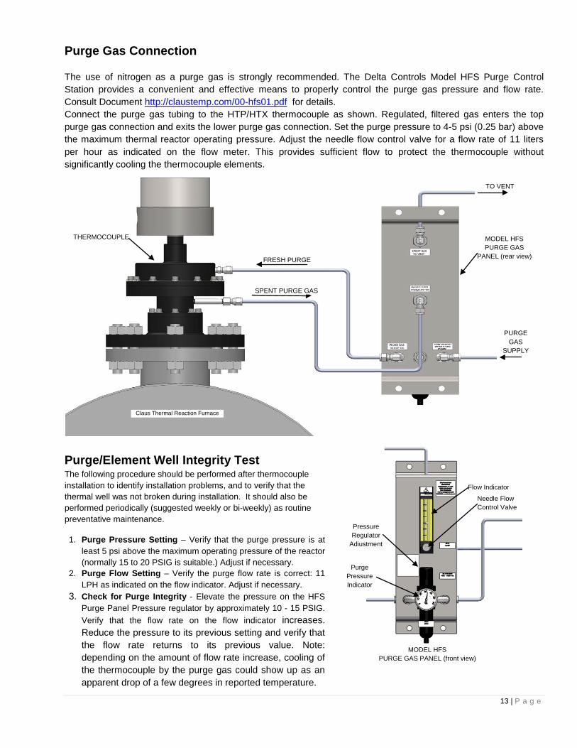
Purge Gas Connection
The use of nitrogen as a purge gas is strongly recommended. The Delta Controls Model HFS Purge Control Station provides a convenient and effective means to properly control the purge gas pressure and flow rate. Consult Document http://claustemp.com/00-hfs01.pdf for details. Connect the purge gas tubing to the HTP/HTX thermocouple as shown. Regulated, filtered gas enters the top purge gas connection and exits the lower purge gas connection. Set the purge pressure to 4-5 psi (0.25 bar) above the maximum thermal reactor operating pressure. Adjust the needle flow control valve for a flow rate of 11 liters per hour as indicated on the flow meter. This provides sufficient flow to protect the thermocouple without significantly cooling the thermocouple elements.
Purge/Element Well Integrity Test The following procedure should be performed after thermocouple installation to identify installation problems, and to verify that the thermal well was not broken during installation. It should also be performed periodically (suggested weekly or bi-weekly) as routine preventative maintenance.
1. Purge Pressure Setting – Verify that the purge pressure is at least 5 psi above the maximum operating pressure of the reactor (normally 15 to 20 PSIG is suitable.) Adjust if necessary.
2. Purge Flow Setting – Verify the purge flow rate is correct: 11 LPH as indicated on the flow indicator. Adjust if necessary.
3. Check for Purge Integrity - Elevate the pressure on the HFS Purge Panel Pressure regulator by approximately 10 - 15 PSIG. Verify that the flow rate on the flow indicator increases. Reduce the pressure to its previous setting and verify that the flow rate returns to its previous value. Note: depending on the amount of flow rate increase, cooling of the thermocouple by the purge gas could show up as an apparent drop of a few degrees in reported temperature.
TO VENT
PURGE GAS
SUPPLY
MODEL HFS PURGE GAS
PANEL (rear view)
FRESH PURGE
SPENT PURGE GAS
THERMOCOUPLE
Claus Thermal Reaction Furnace
14 | P a g e
Failure of the flow indicator to respond to changes in purge pressure can indicate: • Leaks – which will allow the purge gas to escape to atmosphere and not return to the flow indicator. • Breakage of the element well – Which allows purge gas to escape into the reaction vessel and allows reaction gases
to contact the thermocouple element, leading to increasing inaccuracy and ultimately complete failure from contamination and corrosion.
• Plugging of the purge lines – usually, this is caused by an element well breakage. Sulfur condenses in the purge lines and plugs them. Such a condition is often accompanied by a visible yellow sulfur deposit on the inside surface of the glass flow indicator.
Technical Operation and Maintenance .
Pre-Commissioning/Commissioning Procedure (Startup) Make sure that the purge is properly supplied to the thermocouple prior to reactor startup.
Use the Pressure Regulator adjustment on the HFS purge panel to set the Purge Pressure to approximately 5 psi above the maximum operating pressure of the reactor.
Using the Needle Flow Control Valve on the HFS purge panel, adjust the purge flow rate to 11 LPH as shown on the flow indicator.
Shutdown Continue purging the thermocouple during shutdown until the reactor has cooled and reaction gases are no longer present in the reactor.
Operation The thermocouple has no adjustments or controls. Operation consists of maintaining purge gas flow to the thermocouple.
Maintenance No periodic maintenance is required on the thermocouple. It is recommended that the Purge/Element Well Integrity Test on page 13 be performed on a weekly or bi-weekly basis in order to assure that purge is maintained to the thermocouple and to detect any breakage of the thermal well (which would lead to subsequent failure of the thermocouple due to exposure to corrosive gases.) Such breakage is sometimes cause by shifting of the refractory due to thermal expansion. When properly installed, the thermal well can withstand some shifting of the refractory, but large shifts can cause failures.
Troubleshooting For diagnostic procedures, see Delta Controls document AN-HTP39, available at www.claustemp.com/an-htp39.pdf

15 | P a g e
Specifications Absolute Maximum Ratings:
Maximum Operating Pressure: 10 bar (150psi) Maximum Gas Purge Pressure 10 bar (150psi) Maximum Operating Temperature: 1700ºC (3092ºF)* Minimum Operating Temperature: -20ºC (-4ºF) Maximum Flange Temperature: 260ºC (500ºF) Maximum Terminal Enclosure Temperature 195ºC (383ºF)
Terminal Enclosure Rating II 2 G EEx IIB+H2 T3 IP65 T/C types: B,S,R,K,T (“C” non-standard) Materials: Flange material: SA-516-70 Carbon Steel Trim/Bolting/Seats: Stainless Steel Protective well: Blended alumina, ceramic Purge Requirements: dry nitrogen, 0.4scfh * type ‘B’ thermocouple. Max operating temperature is limited by the thermocouple melting point.
Model Numbering System
The model HTX should only be used in industrial category 2 Hazardous Locations consistent with the device markings:
“X” behind the approval number indicates special conditions for safe use. The electrical enclosure body must not exceed the ignition temperature of the explosive gas that may be present, with a maximum temperature of 195 ºC
II d G/D, EEx d IIB+H2 IP65 T3
M/N MOUNTING FLANGE AA NONE NP NOZZLE PURGE CONNECTION 1/8” FNPT NIS NIST ACCURACY CERTIFICATION XPG CL1, DIV 1, GRPS BCD; HOSEPROOF XPB SAME, EXCEPT 300 S.S. HEAD; NACE
BV BLOCKVALVE FOR REDUNDANT SAFETY SHUTOFF, FIRESAFE TYPE
ZZ CUSTOM ADAPTATIONS & MODS
M/N DESCRIPTION HTP BASIC SENSOR
HTX BASIC SENSOR
NOTES: (1) Temperature shown is the maximum
recommended for continuous service (2) Accuracy of type “T” dryout T/C: ±0.9°F
(0.5°C) or better at 212°F (100°C); limited 660°F (320°C) in nitrogen
M/N DESCRIPTION °F 1 °C T2 COPPER vs. CONSTANTAN (DRYOUT ONLY) 660 320 R PLATINUM vs. PLATINUM +13% RHODIUM 2700 1480 B PLATINUM. +6%RH vs. PLATINUM. +30%RH. 3050 1675 ZZ SPECIAL ELEMENT MATERIAL AVAILABLE 4000 2200
M/N MOUNTING FLANGE 6”150RS ANSI 6 INCH 150# RAISED FACE, STEEL
ZZ OTHER STYLES, TYPES & SIZES
SPECIFY INCHES LENGTH (dimension F
on front cover)
HTP
BASICTYPE FLANGE
MOUNTINGOPERATING
R
T/CREFERENCE
R
T/CDRYOUT
T/C
T 11.5"
OPTIONS
6"/150 RS NP
INCHES OFINSERTION
HTX

16 | P a g e
Dimensions
3.6”(91)
6” (152)
9.3” (236)
13.8” (350)
Dim ‘F’ on front cover
1/8” NPTM (std)
3/4” NPT (std) 2.6”
(67)
3.5” (87)
Model HTX Thermocouple
3/4” NPT (std)
2.2” (55)
2.6” (67)
2.2” (55)
Model HTP Thermocouple
Dim ‘F’ on front cover
3.2”(80)
6.6” (167)
10.2” (258)
14.6” (371)
1/8” NPTM
1/8” NPTF

17 | P a g e
585 Fortson Street Shreveport, LA 71107 USA
Ph: +1(318) 424-8471 Fax: +1(318) 425-2421
E-mail: [email protected] Web: www.claustemp.com
Engineered Sensors – For Difficult Services