Maintenance and Safety Manual htx maintenance... · 704-0211-211 Maintenance and Safety Manual...
124
704-0211-211 Maintenance and Safety Manual VTX/HTX Machining Centers August, 2004 Maintenance and Safety Manual for Hurco VTX/HTX Machining Centers Hurco Manufacturing Company reserves the right to incorporate any modifications or improvements in machines and machine specifications which it considers necessary, and does not assume any obligation to make any said changes in machines or equipment previously sold. Hurco products and services are subject to Hurco’s then current prices, terms, and conditions, which are subject to change without notice.
Transcript of Maintenance and Safety Manual htx maintenance... · 704-0211-211 Maintenance and Safety Manual...
704-0211-211
Maintenance and Safety Manual
VTX/HTX Machining Centers
August, 2004
Maintenance andSafety Manual
for HurcoVTX/HTX Machining Centers
Hurco Manufacturing Company reserves the right to incorporate anymodifications or improvements in machines and machine specifications whichit considers necessary, and does not assume any obligation to make any saidchanges in machines or equipment previously sold.
Hurco products and services are subject to Hurco’s then current prices, terms,and conditions, which are subject to change without notice.
The information in this document is subject to change without notice and does not represent a commitment on the part of Hurco Companies, Inc. (Hurco). The software described in this document is furnished under the License Agreement to customers. It is against the law to copy the software on any medium except as specifically allowed in the license agreement. The purchaser may make copies of the software for backup purposes. No part of this document may be reproduced or transmitted in any form or by any means, electronic or mechanical, including photocopying, for any purpose without the express written permission of Hurco.
© 2001-2004 Hurco Companies, Inc. All rights reserved.
Patents:
U.S. Patents B14,477,754; 5,453,933; Canadian Patent 1,102,434; Japanese Patents 1,649,006 and 1,375,124; other Patents pending.
Hurco and Ultimax are Registered Trademarks of Hurco Companies, Inc.UltiPocket and AutoSave are trademarks of Hurco Companies, IncAutoCAD, Autodesk, and DXF are registered trademarks of Autodesk, Inc.Fanuc is a registered trademark of Fanuc LTD.IBM and PC/AT are registered trademarks of International Business Machines Corporation.MS-DOS and Microsoft are registered trademarks of Microsoft Corporation.
Many of the designations used by manufacturers and sellers to distinguish their products are claimed as trademarks. Hurco has listed here all trademarks of which it is aware. For more information about Hurco products and services, contact:
Hurco Companies, Inc.
One Technology WayP.O. Box 68180Indianapolis, IN 46268-0180Tel (317) 293-5309 (products)
(317) 298-2635 (service)Fax (317) 328-2812 (service)
For Hurco subsidiary contact information, go to Hurco’s website:
www.hurco.com

704-0211-211 August, 2004 VTX/HTX Maintenance & Safety Manual
VMX Maintenance Checklist
PageDaily (Every 8-10 Hours)
�
Clean and lubricate spindle taper . . . . . . . . . . . . . . . . . . . . . . . . . . . . . . . . . . . 3-1
�
Perform daily operational checks . . . . . . . . . . . . . . . . . . . . . . . . . . . . . . . . . . . 3-1
�
Clean machine. . . . . . . . . . . . . . . . . . . . . . . . . . . . . . . . . . . . . . . . . . . . . . . . . . 3-2
�
Inspect floppy drive and diskettes for dirt or damage . . . . . . . . . . . . . . . . . . . . 3-2
�
Make sure all lubricant levels are correct . . . . . . . . . . . . . . . . . . . . . . . . . . . . . 3-4
�
Inspect/clean tool lock pins . . . . . . . . . . . . . . . . . . . . . . . . . . . . . . . . . . . . . . . 3-13
�
Make sure the FRL Unit air pressure is correct . . . . . . . . . . . . . . . . . . . . . . . . 3-14
�
Inspect/clean coolant levels and filters . . . . . . . . . . . . . . . . . . . . . . . . . . . . . . . 3-18
�
Clean chip screens. . . . . . . . . . . . . . . . . . . . . . . . . . . . . . . . . . . . . . . . . . . . . . . 3-19
Weekly (Every 40-50 Hours)
�
Clean heat exchanger filter . . . . . . . . . . . . . . . . . . . . . . . . . . . . . . . . . . . . . . . . 3-3
�
Make sure the filler screen is clean . . . . . . . . . . . . . . . . . . . . . . . . . . . . . . . . . . 3-9
�
Refill the autolube reservoir . . . . . . . . . . . . . . . . . . . . . . . . . . . . . . . . . . . . . . . 3-10
�
Make sure the auto moisture drain on FRL unit operates correctly . . . . . . . . . 3-15
�
Clean oil chiller filter . . . . . . . . . . . . . . . . . . . . . . . . . . . . . . . . . . . . . . . . . . . . 3-16
Monthly (Every 150-200 Hours)
�
Inspect external conduit, cabling and wiring for signs of wear or damage . . . 3-3
�
Inspect tool holders for damage or excess wear . . . . . . . . . . . . . . . . . . . . . . . . 3-13
�
Make sure limit switch and dog fasteners are tight. . . . . . . . . . . . . . . . . . . . . . 3-20
Every 3 Months (Every 500 Hours)
�
Clean/replace FRL filter element . . . . . . . . . . . . . . . . . . . . . . . . . . . . . . . . . . . 3-15
�
Drain moisture from the air lines . . . . . . . . . . . . . . . . . . . . . . . . . . . . . . . . . . . 3-15
�
Clean/replace coolant filters and change coolant . . . . . . . . . . . . . . . . . . . . . . . 3-17
�
Clean chip conveyor tank . . . . . . . . . . . . . . . . . . . . . . . . . . . . . . . . . . . . . . . . . 3-19
�
Measure ground impedance (resistance to true earth) . . . . . . . . . . . . . . . . . . . 3-20
Every 6 Months (Every 1000 Hours)
�
Grease rotary (tilt axis) incline shaft side (VTXU only) . . . . . . . . . . . . . . . . . 3-4
�
Grease rotary (tilt axis) incline shaft side gearcase (VTXU only) . . . . . . . . . . 3-4
�
Grease rotary table gearbox (HTX500 only) . . . . . . . . . . . . . . . . . . . . . . . . . . 3-6
�
Grease rotary table side (refer to HTX500 lubrication table) . . . . . . . . . . . . . . 3-6
�
Grease rotary union bearing assembly . . . . . . . . . . . . . . . . . . . . . . . . . . . . . . . 3-11
�
Make sure the machine is level . . . . . . . . . . . . . . . . . . . . . . . . . . . . . . . . . . . . . 3-20
Annually (Every 2000 Hours)
�
Replace autolube reservoir suction filter. . . . . . . . . . . . . . . . . . . . . . . . . . . . . . 3-7
�
Replace ATC cam oil . . . . . . . . . . . . . . . . . . . . . . . . . . . . . . . . . . . . . . . . . . . . 3-11
�
Replace ATC gearbox oil (HTX500 only) . . . . . . . . . . . . . . . . . . . . . . . . . . . . 3-11

This Page Intentionally Left Blank.

VTX/HTX Maintenance & Safety Manual August, 2004 i
Using This Manual
Standard Text Icons
This manual may contain the following icons:
Caution
The machine may be damaged, or a part ruined, if the described procedure is not followed.
Hints and Tricks
Useful suggestions that show creative uses of the Ultimax features.
Important
Ensures proper operation of the machine and control.
Troubleshooting
Steps that can be taken to solve potential problems.
Warning
The operator may be injured and the machining center severely damaged if the described procedure is not followed.
Where can we go from here?
Lists several possible options the operator can take.
TOC
Displays the Table of Contents
HURCO

ii 704-0211-211 VTX/HTX Maintenance & Safety Manual
This Page Intentionally Left Blank.

VTX/HTX Maintenance & Safety Manual August, 2004 iii
Table of Contents
PageMachine Components
Overview. . . . . . . . . . . . . . . . . . . . . . . . . . . . . . . . . . . . . . . . . . . . . . . . . . . . . . 1-1Machine Model Name. . . . . . . . . . . . . . . . . . . . . . . . . . . . . . . . . . . . . . . . . . . . 1-1Frame . . . . . . . . . . . . . . . . . . . . . . . . . . . . . . . . . . . . . . . . . . . . . . . . . . . . . . . . 1-2
Table . . . . . . . . . . . . . . . . . . . . . . . . . . . . . . . . . . . . . . . . . . . . . . . . . . . 1-2Head . . . . . . . . . . . . . . . . . . . . . . . . . . . . . . . . . . . . . . . . . . . . . . . . . . . 1-3Guideways. . . . . . . . . . . . . . . . . . . . . . . . . . . . . . . . . . . . . . . . . . . . . . . 1-3Switches and Sensors . . . . . . . . . . . . . . . . . . . . . . . . . . . . . . . . . . . . . . 1-3
Enclosure. . . . . . . . . . . . . . . . . . . . . . . . . . . . . . . . . . . . . . . . . . . . . . . . . . . . . . 1-4Spindle and Drive System. . . . . . . . . . . . . . . . . . . . . . . . . . . . . . . . . . . . . . . . . 1-6
Spindle . . . . . . . . . . . . . . . . . . . . . . . . . . . . . . . . . . . . . . . . . . . . . . . . . 1-6AC Spindle Drive Unit . . . . . . . . . . . . . . . . . . . . . . . . . . . . . . . . . . . . . 1-7
Electronic Spindle Orientation . . . . . . . . . . . . . . . . . . . . . . . . . . . 1-7Proximity Sensor Spindle Orientation . . . . . . . . . . . . . . . . . . . . . 1-8
Spindle Motor . . . . . . . . . . . . . . . . . . . . . . . . . . . . . . . . . . . . . . . . . . . . 1-8Tool Retention Knobs . . . . . . . . . . . . . . . . . . . . . . . . . . . . . . . . . . . . . . 1-8
Axes Motion System. . . . . . . . . . . . . . . . . . . . . . . . . . . . . . . . . . . . . . . . . . . . . 1-9Servo Motors. . . . . . . . . . . . . . . . . . . . . . . . . . . . . . . . . . . . . . . . . . . . . 1-10Ballscrews and Bearings . . . . . . . . . . . . . . . . . . . . . . . . . . . . . . . . . . . . 1-10Feedback Systems. . . . . . . . . . . . . . . . . . . . . . . . . . . . . . . . . . . . . . . . . 1-10
Machine Electrical Cabinet. . . . . . . . . . . . . . . . . . . . . . . . . . . . . . . . . . . . . . . . 1-10Safety Procedures for Electrical Service. . . . . . . . . . . . . . . . . . . . . . . . 1-10
Handling Printed Circuit Boards. . . . . . . . . . . . . . . . . . . . . . . . . . 1-11Electrical Cabinet Components. . . . . . . . . . . . . . . . . . . . . . . . . . . . . . . 1-12
Electrical Cabinet Operating Temperature . . . . . . . . . . . . . . . . . . 1-12Electrical Cabinet Layout . . . . . . . . . . . . . . . . . . . . . . . . . . . . . . . 1-12Power Supply . . . . . . . . . . . . . . . . . . . . . . . . . . . . . . . . . . . . . . . . 1-12CNC Electronics . . . . . . . . . . . . . . . . . . . . . . . . . . . . . . . . . . . . . . 1-12
Ultimax ISA Control Card Rack. . . . . . . . . . . . . . . . . . . . . 1-13Main CPU Board. . . . . . . . . . . . . . . . . . . . . . . . . . . . . . . . . 1-13Peripheral Interface. . . . . . . . . . . . . . . . . . . . . . . . . . . . . . . 1-13VGA Board . . . . . . . . . . . . . . . . . . . . . . . . . . . . . . . . . . . . . 1-14Motion Control Board. . . . . . . . . . . . . . . . . . . . . . . . . . . . . 1-14CANbus Controller Board . . . . . . . . . . . . . . . . . . . . . . . . . 1-14CANbus DC I/O Backplane . . . . . . . . . . . . . . . . . . . . . . . . 1-14I/O Interface Board . . . . . . . . . . . . . . . . . . . . . . . . . . . . . . . 1-15CANbus DC I/O Node . . . . . . . . . . . . . . . . . . . . . . . . . . . . 1-15

iv 704-0211-211 VTX/HTX Maintenance & Safety Manual
Communication Ports. . . . . . . . . . . . . . . . . . . . . . . . . . . . . . . . . . 1-16RS-232-C Serial Ports. . . . . . . . . . . . . . . . . . . . . . . . . . . . . 1-17Indexer Port. . . . . . . . . . . . . . . . . . . . . . . . . . . . . . . . . . . . . 1-19Network Ports . . . . . . . . . . . . . . . . . . . . . . . . . . . . . . . . . . . 1-19
Operator Control Console . . . . . . . . . . . . . . . . . . . . . . . . . . . . . . . . . . . . . . . . . 1-19Flat Panel Node PCB . . . . . . . . . . . . . . . . . . . . . . . . . . . . . . . . . . . . . . . . . . . . 1-21Coolant System . . . . . . . . . . . . . . . . . . . . . . . . . . . . . . . . . . . . . . . . . . . . . . . . . 1-21Pneumatic System. . . . . . . . . . . . . . . . . . . . . . . . . . . . . . . . . . . . . . . . . . . . . . . 1-22VTX Automatic Tool Changer . . . . . . . . . . . . . . . . . . . . . . . . . . . . . . . . . . . . . 1-23
ATC Diagnostics for VTX Machines . . . . . . . . . . . . . . . . . . . . . . . . . . 1-24General Status Conditions. . . . . . . . . . . . . . . . . . . . . . . . . . . . . . . 1-26ATC Diagnostics Softkeys . . . . . . . . . . . . . . . . . . . . . . . . . . . . . . 1-27
IO Maps for VTX Machines . . . . . . . . . . . . . . . . . . . . . . . . . . . . . . . . . 1-29HTX Automatic Tool Changer . . . . . . . . . . . . . . . . . . . . . . . . . . . . . . . . . . . . . 1-31
ATC Diagnostics for HTX Machines . . . . . . . . . . . . . . . . . . . . . . . . . . 1-32Status Conditions . . . . . . . . . . . . . . . . . . . . . . . . . . . . . . . . . . . . . 1-33ATC Diagnostics Softkeys . . . . . . . . . . . . . . . . . . . . . . . . . . . . . . 1-34
IO Maps for HTX Machines . . . . . . . . . . . . . . . . . . . . . . . . . . . . . . . . . 1-36Machine Diagnostics. . . . . . . . . . . . . . . . . . . . . . . . . . . . . . . . . . . . . . . 1-40Machine Parameters . . . . . . . . . . . . . . . . . . . . . . . . . . . . . . . . . . . . . . . 1-42
Warm-up Cycle Time, Warm-up Spindle Speed 1, 2, and 3,and Warm-up Axis Feed Rate . . . . . . . . . . . . . . . . . . . . . . . . . . 1-43
Coolant Delay Time (sec) . . . . . . . . . . . . . . . . . . . . . . . . . . . . . . . 1-44Pulsating Washdown Enable . . . . . . . . . . . . . . . . . . . . . . . . . . . . . 1-44Alt Washdown Dwell (0.01 sec) . . . . . . . . . . . . . . . . . . . . . . . . . . 1-44Alt Dwell Lt Side (0.01 sec) . . . . . . . . . . . . . . . . . . . . . . . . . . . . . 1-44Alt Washdown Off Time (0.01 sec) . . . . . . . . . . . . . . . . . . . . . . . 1-45Cal to LS Velocity X, Y, Z, A, B, C. . . . . . . . . . . . . . . . . . . . . . . . 1-45Auto Balance Enable. . . . . . . . . . . . . . . . . . . . . . . . . . . . . . . . . . . 1-46ATC Disable . . . . . . . . . . . . . . . . . . . . . . . . . . . . . . . . . . . . . . . . . 1-46Rapid Override Disable. . . . . . . . . . . . . . . . . . . . . . . . . . . . . . . . . 1-46Tilt Axis Safety Position (deg) . . . . . . . . . . . . . . . . . . . . . . . . . . . 1-47Aux Output 1, 2, 3, 4 Confirmation Enable . . . . . . . . . . . . . . . . . 1-47Disable Aux Out 1, 2, 3, 4 During Interrupt . . . . . . . . . . . . . . . . . 1-48SSM Mouse Scaling Factor . . . . . . . . . . . . . . . . . . . . . . . . . . . . . 1-48Move to Safety Pos Manual Mode ATC . . . . . . . . . . . . . . . . . . . . 1-48
Automatic Pallet Changer System . . . . . . . . . . . . . . . . . . . . . . . . . . . . . . . . . . 1-49Pallet Changer Solenoids and Adjustment . . . . . . . . . . . . . . . . . . . . . . 1-49Squaring the APC Table . . . . . . . . . . . . . . . . . . . . . . . . . . . . . . . . . . . . 1-50
Table of Contents

VTX/HTX Maintenance & Safety Manual August, 2004 v
Manual Pallet Changer Operation. . . . . . . . . . . . . . . . . . . . . . . . . . . . . 1-50Example of Manual Pallet Changer Operation . . . . . . . . . . . . . . . 1-53
Manual APC Table Rotation . . . . . . . . . . . . . . . . . . . . . . . . . . . . . . . . . 1-54Automatic Pallet Changer Operation . . . . . . . . . . . . . . . . . . . . . . . . . . 1-55Pallet Changer Diagnostics . . . . . . . . . . . . . . . . . . . . . . . . . . . . . . . . . . 1-57
APC Diagnostics Softkeys . . . . . . . . . . . . . . . . . . . . . . . . . . . . . . 1-58Status Conditions . . . . . . . . . . . . . . . . . . . . . . . . . . . . . . . . . . . . . 1-59
Machine StandardsEuropean Community Machine Safety Standards . . . . . . . . . . . . . . . . . . . . . . 2-1
Directives . . . . . . . . . . . . . . . . . . . . . . . . . . . . . . . . . . . . . . . . . . . . . . . 2-1Harmonized Standards . . . . . . . . . . . . . . . . . . . . . . . . . . . . . . . . . . . . . 2-1
Safety . . . . . . . . . . . . . . . . . . . . . . . . . . . . . . . . . . . . . . . . . . . . . . 2-1EMC (Electromagnetic Compatibility). . . . . . . . . . . . . . . . . . . . . 2-1
Other Standards. . . . . . . . . . . . . . . . . . . . . . . . . . . . . . . . . . . . . . . . . . . 2-1Safe Installation of Guarding System and Machine . . . . . . . . . . . . . . . . . . . . . 2-2
Guarding System. . . . . . . . . . . . . . . . . . . . . . . . . . . . . . . . . . . . . . . . . . 2-2Machine. . . . . . . . . . . . . . . . . . . . . . . . . . . . . . . . . . . . . . . . . . . . . . . . . 2-2
Foundation Conditions . . . . . . . . . . . . . . . . . . . . . . . . . . . . . . . . . 2-2Electrical Service Requirements . . . . . . . . . . . . . . . . . . . . . . . . . . 2-3
Connecting Electrical Service. . . . . . . . . . . . . . . . . . . . . . . 2-3Recommended Isolation Transformer Configuration . . . . . 2-4Grounding Equipment. . . . . . . . . . . . . . . . . . . . . . . . . . . . . 2-5
Compressed Air Requirements . . . . . . . . . . . . . . . . . . . . . . . . . . . . . . . 2-5Compressed Air Specification. . . . . . . . . . . . . . . . . . . . . . . . . . . . 2-5Connecting Compressed Air . . . . . . . . . . . . . . . . . . . . . . . . . . . . . 2-5
Anti-Vibration Mountings. . . . . . . . . . . . . . . . . . . . . . . . . . . . . . . . . . . 2-6Initial Test and Examination . . . . . . . . . . . . . . . . . . . . . . . . . . . . . . . . . . . . . . . 2-6Safety Circuits. . . . . . . . . . . . . . . . . . . . . . . . . . . . . . . . . . . . . . . . . . . . . . . . . . 2-7
Guidelines . . . . . . . . . . . . . . . . . . . . . . . . . . . . . . . . . . . . . . . . . . . . . . . 2-7CE Safety Circuits Commissioning Checklist . . . . . . . . . . . . . . . . . . . 2-8
Mode: Manual Setup. . . . . . . . . . . . . . . . . . . . . . . . . . . . . . . . . . . 2-8Mode: Automatic Preparation . . . . . . . . . . . . . . . . . . . . . . . . . . . . 2-9Mode: Automatic Production . . . . . . . . . . . . . . . . . . . . . . . . . . . . 2-10
Safe Operation . . . . . . . . . . . . . . . . . . . . . . . . . . . . . . . . . . . . . . . . . . . . . . . . . 2-10Training for Operators . . . . . . . . . . . . . . . . . . . . . . . . . . . . . . . . . . . . . 2-10Setup . . . . . . . . . . . . . . . . . . . . . . . . . . . . . . . . . . . . . . . . . . . . . . . . . . . 2-11Operation and Maintenance . . . . . . . . . . . . . . . . . . . . . . . . . . . . . . . . . 2-11
Table of Contents

vi 704-0211-211 VTX/HTX Maintenance & Safety Manual
Safe Working Practices . . . . . . . . . . . . . . . . . . . . . . . . . . . . . . . . . . . . . 2-12Responsible Conduct . . . . . . . . . . . . . . . . . . . . . . . . . . . . . . . . . . 2-12Personal Care . . . . . . . . . . . . . . . . . . . . . . . . . . . . . . . . . . . . . . . . 2-13Wearing Apparel . . . . . . . . . . . . . . . . . . . . . . . . . . . . . . . . . . . . . . 2-13Heavy Lifting . . . . . . . . . . . . . . . . . . . . . . . . . . . . . . . . . . . . . . . . 2-13Housekeeping . . . . . . . . . . . . . . . . . . . . . . . . . . . . . . . . . . . . . . . . 2-13
Control Systems . . . . . . . . . . . . . . . . . . . . . . . . . . . . . . . . . . . . . . . . . . . . . . . . 2-14Noise Levels . . . . . . . . . . . . . . . . . . . . . . . . . . . . . . . . . . . . . . . . . . . . . . . . . . . 2-14Persons Trapped in Machine. . . . . . . . . . . . . . . . . . . . . . . . . . . . . . . . . . . . . . . 2-15
Machine Maintenance
Daily Operational Checks . . . . . . . . . . . . . . . . . . . . . . . . . . . . . . . . . . . . . . . . . 3-1Cleaning the Machine . . . . . . . . . . . . . . . . . . . . . . . . . . . . . . . . . . . . . . 3-2Floppy Disk Drive and Diskettes . . . . . . . . . . . . . . . . . . . . . . . . . . . . . 3-2Heat Exchanger. . . . . . . . . . . . . . . . . . . . . . . . . . . . . . . . . . . . . . . . . . . 3-3Exterior Wiring . . . . . . . . . . . . . . . . . . . . . . . . . . . . . . . . . . . . . . . . . . . 3-3
Lubrication . . . . . . . . . . . . . . . . . . . . . . . . . . . . . . . . . . . . . . . . . . . . . . . . . . . . 3-4Autolube System. . . . . . . . . . . . . . . . . . . . . . . . . . . . . . . . . . . . . . . . . . 3-7
Check Filler Screen and Fluid Level. . . . . . . . . . . . . . . . . . . . . . . 3-9Activate System Manually . . . . . . . . . . . . . . . . . . . . . . . . . . . . . . 3-9Adjust Autolube Discharge Rate. . . . . . . . . . . . . . . . . . . . . . . . . . 3-9Replace Oil and Suction Filter . . . . . . . . . . . . . . . . . . . . . . . . . . . 3-9
Automatic Tool Changer . . . . . . . . . . . . . . . . . . . . . . . . . . . . . . . . . . . . 3-11ATC Oil Unit. . . . . . . . . . . . . . . . . . . . . . . . . . . . . . . . . . . . . . . . . 3-11
Maintain the Oil Level . . . . . . . . . . . . . . . . . . . . . . . . . . . . 3-11Replace the ATC Oil . . . . . . . . . . . . . . . . . . . . . . . . . . . . . . 3-11
Greasing the Rotary Union Bearing Assembly CTSand CTS-Ready. . . . . . . . . . . . . . . . . . . . . . . . . . . . . . . . . . . . . 3-11
Lubricating the ATC Cam Unit . . . . . . . . . . . . . . . . . . . . . . . . . . . 3-12Greasing the ATC Magazine Chain. . . . . . . . . . . . . . . . . . . . . . . . 3-12Cleaning the Tool Lock Pins . . . . . . . . . . . . . . . . . . . . . . . . . . . . . 3-13Cleaning the Tool Holders . . . . . . . . . . . . . . . . . . . . . . . . . . . . . . 3-13
Pneumatic System FRL Unit . . . . . . . . . . . . . . . . . . . . . . . . . . . . . . . . 3-14Set Air Pressure. . . . . . . . . . . . . . . . . . . . . . . . . . . . . . . . . . . . . . . 3-14Maintain Lubricator Oil Level . . . . . . . . . . . . . . . . . . . . . . . . . . . 3-15Adjust Drip Rate Screw . . . . . . . . . . . . . . . . . . . . . . . . . . . . . . . . 3-15Check and Replace Air Filter Element . . . . . . . . . . . . . . . . . . . . . 3-15Check Auto Moisture Drain . . . . . . . . . . . . . . . . . . . . . . . . . . . . . 3-15
Table of Contents

VTX/HTX Maintenance & Safety Manual August, 2004 vii
Spindle Oil Chiller . . . . . . . . . . . . . . . . . . . . . . . . . . . . . . . . . . . . . . . . 3-16Maintain Oil Level in Spindle Oil Chiller Tank . . . . . . . . . . . . . . 3-16Inspect the Air Filter Screen . . . . . . . . . . . . . . . . . . . . . . . . . . . . . 3-16Maintain Oil in Chiller Tank. . . . . . . . . . . . . . . . . . . . . . . . . . . . . 3-16
Coolant System and Chip Conveyor . . . . . . . . . . . . . . . . . . . . . . . . . . . . . . . . . 3-17Selecting Coolant . . . . . . . . . . . . . . . . . . . . . . . . . . . . . . . . . . . . . . . . . 3-17Preparing Coolant . . . . . . . . . . . . . . . . . . . . . . . . . . . . . . . . . . . . . . . . . 3-18Maintaining the Coolant . . . . . . . . . . . . . . . . . . . . . . . . . . . . . . . . . . . . 3-18Replacing Coolant. . . . . . . . . . . . . . . . . . . . . . . . . . . . . . . . . . . . . . . . . 3-18Coolant Filter for CTS . . . . . . . . . . . . . . . . . . . . . . . . . . . . . . . . . . . . . 3-19Chip Conveyor Tank . . . . . . . . . . . . . . . . . . . . . . . . . . . . . . . . . . . . . . . 3-19
Limit Switches and Dogs . . . . . . . . . . . . . . . . . . . . . . . . . . . . . . . . . . . . . . . . . 3-20Machine Electrical Ground . . . . . . . . . . . . . . . . . . . . . . . . . . . . . . . . . . . . . . . . 3-20Machine Level. . . . . . . . . . . . . . . . . . . . . . . . . . . . . . . . . . . . . . . . . . . . . . . . . . 3-20Spindle Taper . . . . . . . . . . . . . . . . . . . . . . . . . . . . . . . . . . . . . . . . . . . . . . . . . . 3-20Troubleshooting . . . . . . . . . . . . . . . . . . . . . . . . . . . . . . . . . . . . . . . . . . . . . . . . 3-21
Power-Up Troubleshooting . . . . . . . . . . . . . . . . . . . . . . . . . . . . . . . . . . 3-21No Response on the Console . . . . . . . . . . . . . . . . . . . . . . . . . . . . 3-21
Initialization Error Messages . . . . . . . . . . . . . . . . . . . . . . . . . . . . . . . . 3-22Error Messages on Input Screen . . . . . . . . . . . . . . . . . . . . . . . . . . . . . . 3-23
Corrective Measures . . . . . . . . . . . . . . . . . . . . . . . . . . . . . . . . . . . 3-23Swap Out a Printed Circuit Board . . . . . . . . . . . . . . . . . . . 3-23Check Wiring . . . . . . . . . . . . . . . . . . . . . . . . . . . . . . . . . . . 3-23Perform a Reset. . . . . . . . . . . . . . . . . . . . . . . . . . . . . . . . . . 3-24
Emergency Stop Condition . . . . . . . . . . . . . . . . . . . . . . . . . . . . . . 3-24Machine Diagnostics. . . . . . . . . . . . . . . . . . . . . . . . . . . . . . . . . . . 3-24
Common Problems . . . . . . . . . . . . . . . . . . . . . . . . . . . . . . . . . . . . . . . . 3-25Power-on Self Test . . . . . . . . . . . . . . . . . . . . . . . . . . . . . . . . . . . . 3-25Machine Voltages . . . . . . . . . . . . . . . . . . . . . . . . . . . . . . . . . . . . . 3-25Coolant System . . . . . . . . . . . . . . . . . . . . . . . . . . . . . . . . . . . . . . . 3-27Motion and Spindle Rotation . . . . . . . . . . . . . . . . . . . . . . . . . . . . 3-28Environmental Conditions . . . . . . . . . . . . . . . . . . . . . . . . . . . . . . 3-30
Ordering Replacement Parts . . . . . . . . . . . . . . . . . . . . . . . . . . . . . . . . . . . . . . . 3-31Providing Information Required for Parts Orders. . . . . . . . . . . . . . . . . . . . . . . 3-31Returning Parts . . . . . . . . . . . . . . . . . . . . . . . . . . . . . . . . . . . . . . . . . . . . . . . . . 3-32
Record of Changes
Table of Contents

viii 704-0211-211 VTX/HTX Maintenance & Safety Manual
This Page Intentionally Left Blank.
VTX/HTX Maintenance & Safety Manual August, 2004 ix
Figure List
Page
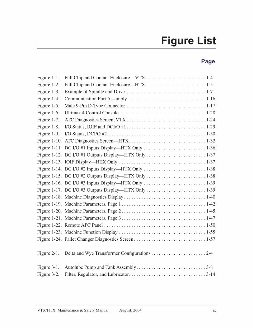
Figure 1-1. Full Chip and Coolant Enclosure—VTX . . . . . . . . . . . . . . . . . . . . . . . . 1-4
Figure 1-2. Full Chip and Coolant Enclosure—HTX . . . . . . . . . . . . . . . . . . . . . . . . 1-5
Figure 1-3. Example of Spindle and Drive . . . . . . . . . . . . . . . . . . . . . . . . . . . . . . . . 1-7
Figure 1-4. Communication Port Assembly . . . . . . . . . . . . . . . . . . . . . . . . . . . . . . . 1-16
Figure 1-5. Male 9-Pin D-Type Connector . . . . . . . . . . . . . . . . . . . . . . . . . . . . . . . . 1-17
Figure 1-6. Ultimax 4 Control Console . . . . . . . . . . . . . . . . . . . . . . . . . . . . . . . . . . . 1-20
Figure 1-7. ATC Diagnostics Screen, VTX . . . . . . . . . . . . . . . . . . . . . . . . . . . . . . . . 1-24
Figure 1-8. I/O Status, IOIF and DCI/O #1 . . . . . . . . . . . . . . . . . . . . . . . . . . . . . . . . 1-29
Figure 1-9. I/O Stauts, DCI/O #2. . . . . . . . . . . . . . . . . . . . . . . . . . . . . . . . . . . . . . . . 1-30
Figure 1-10. ATC Diagnostics Screen—HTX. . . . . . . . . . . . . . . . . . . . . . . . . . . . . . . 1-32
Figure 1-11. DC I/O #1 Inputs Display—HTX Only . . . . . . . . . . . . . . . . . . . . . . . . . 1-36
Figure 1-12. DC I/O #1 Outputs Display—HTX Only . . . . . . . . . . . . . . . . . . . . . . . . 1-37
Figure 1-13. IOIF Display—HTX Only . . . . . . . . . . . . . . . . . . . . . . . . . . . . . . . . . . . 1-37
Figure 1-14. DC I/O #2 Inputs Display—HTX Only . . . . . . . . . . . . . . . . . . . . . . . . . 1-38
Figure 1-15. DC I/O #2 Outputs Display—HTX Only . . . . . . . . . . . . . . . . . . . . . . . . 1-38
Figure 1-16. DC I/O #3 Inputs Display—HTX Only . . . . . . . . . . . . . . . . . . . . . . . . . 1-39
Figure 1-17. DC I/O #3 Outputs Display—HTX Only . . . . . . . . . . . . . . . . . . . . . . . . 1-39
Figure 1-18. Machine Diagnostics Display . . . . . . . . . . . . . . . . . . . . . . . . . . . . . . . . . 1-40
Figure 1-19. Machine Parameters, Page 1 . . . . . . . . . . . . . . . . . . . . . . . . . . . . . . . . . . 1-42
Figure 1-20. Machine Parameters, Page 2 . . . . . . . . . . . . . . . . . . . . . . . . . . . . . . . . . . 1-45
Figure 1-21. Machine Parameters, Page 3 . . . . . . . . . . . . . . . . . . . . . . . . . . . . . . . . . . 1-47
Figure 1-22. Remote APC Panel . . . . . . . . . . . . . . . . . . . . . . . . . . . . . . . . . . . . . . . . . 1-50
Figure 1-23. Machine Function Display . . . . . . . . . . . . . . . . . . . . . . . . . . . . . . . . . . . 1-55
Figure 1-24. Pallet Changer Diagnostics Screen . . . . . . . . . . . . . . . . . . . . . . . . . . . . . 1-57
Figure 2-1. Delta and Wye Transformer Configurations . . . . . . . . . . . . . . . . . . . . . . 2-4
Figure 3-1. Autolube Pump and Tank Assembly. . . . . . . . . . . . . . . . . . . . . . . . . . . . 3-8
Figure 3-2. Filter, Regulator, and Lubricator. . . . . . . . . . . . . . . . . . . . . . . . . . . . . . . 3-14
x 704-0211-211 VTX/HTX Maintenance & Safety Manual
Table List
Page
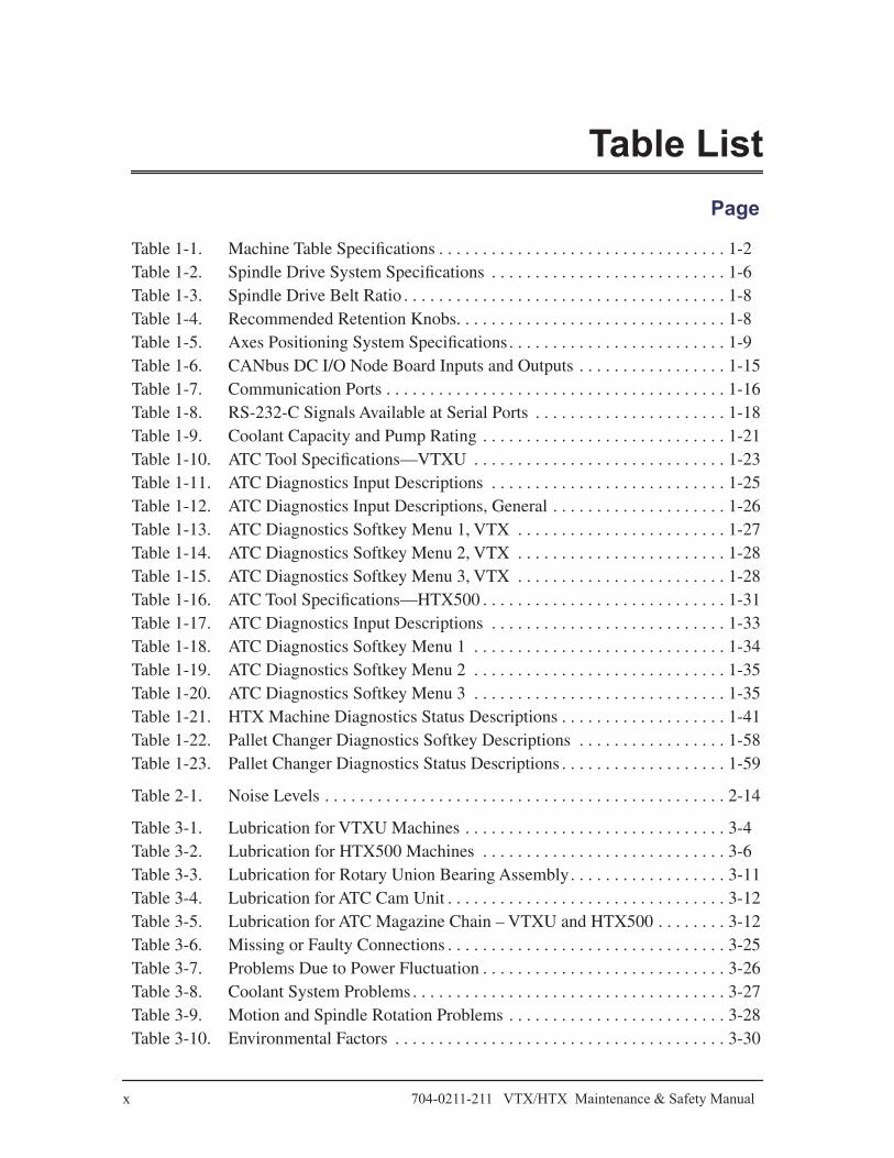
Table 1-1. Machine Table Specifications . . . . . . . . . . . . . . . . . . . . . . . . . . . . . . . . . 1-2Table 1-2. Spindle Drive System Specifications . . . . . . . . . . . . . . . . . . . . . . . . . . . 1-6Table 1-3. Spindle Drive Belt Ratio . . . . . . . . . . . . . . . . . . . . . . . . . . . . . . . . . . . . . 1-8Table 1-4. Recommended Retention Knobs. . . . . . . . . . . . . . . . . . . . . . . . . . . . . . . 1-8Table 1-5. Axes Positioning System Specifications. . . . . . . . . . . . . . . . . . . . . . . . . 1-9Table 1-6. CANbus DC I/O Node Board Inputs and Outputs . . . . . . . . . . . . . . . . . 1-15Table 1-7. Communication Ports . . . . . . . . . . . . . . . . . . . . . . . . . . . . . . . . . . . . . . . 1-16Table 1-8. RS-232-C Signals Available at Serial Ports . . . . . . . . . . . . . . . . . . . . . . 1-18Table 1-9. Coolant Capacity and Pump Rating . . . . . . . . . . . . . . . . . . . . . . . . . . . . 1-21Table 1-10. ATC Tool Specifications—VTXU . . . . . . . . . . . . . . . . . . . . . . . . . . . . . 1-23Table 1-11. ATC Diagnostics Input Descriptions . . . . . . . . . . . . . . . . . . . . . . . . . . . 1-25Table 1-12. ATC Diagnostics Input Descriptions, General . . . . . . . . . . . . . . . . . . . . 1-26Table 1-13. ATC Diagnostics Softkey Menu 1, VTX . . . . . . . . . . . . . . . . . . . . . . . . 1-27Table 1-14. ATC Diagnostics Softkey Menu 2, VTX . . . . . . . . . . . . . . . . . . . . . . . . 1-28Table 1-15. ATC Diagnostics Softkey Menu 3, VTX . . . . . . . . . . . . . . . . . . . . . . . . 1-28Table 1-16. ATC Tool Specifications—HTX500 . . . . . . . . . . . . . . . . . . . . . . . . . . . . 1-31Table 1-17. ATC Diagnostics Input Descriptions . . . . . . . . . . . . . . . . . . . . . . . . . . . 1-33Table 1-18. ATC Diagnostics Softkey Menu 1 . . . . . . . . . . . . . . . . . . . . . . . . . . . . . 1-34Table 1-19. ATC Diagnostics Softkey Menu 2 . . . . . . . . . . . . . . . . . . . . . . . . . . . . . 1-35Table 1-20. ATC Diagnostics Softkey Menu 3 . . . . . . . . . . . . . . . . . . . . . . . . . . . . . 1-35Table 1-21. HTX Machine Diagnostics Status Descriptions . . . . . . . . . . . . . . . . . . . 1-41Table 1-22. Pallet Changer Diagnostics Softkey Descriptions . . . . . . . . . . . . . . . . . 1-58Table 1-23. Pallet Changer Diagnostics Status Descriptions . . . . . . . . . . . . . . . . . . . 1-59
Table 2-1. Noise Levels . . . . . . . . . . . . . . . . . . . . . . . . . . . . . . . . . . . . . . . . . . . . . . 2-14
Table 3-1. Lubrication for VTXU Machines . . . . . . . . . . . . . . . . . . . . . . . . . . . . . . 3-4Table 3-2. Lubrication for HTX500 Machines . . . . . . . . . . . . . . . . . . . . . . . . . . . . 3-6Table 3-3. Lubrication for Rotary Union Bearing Assembly. . . . . . . . . . . . . . . . . . 3-11Table 3-4. Lubrication for ATC Cam Unit . . . . . . . . . . . . . . . . . . . . . . . . . . . . . . . . 3-12Table 3-5. Lubrication for ATC Magazine Chain – VTXU and HTX500 . . . . . . . . 3-12Table 3-6. Missing or Faulty Connections . . . . . . . . . . . . . . . . . . . . . . . . . . . . . . . . 3-25Table 3-7. Problems Due to Power Fluctuation . . . . . . . . . . . . . . . . . . . . . . . . . . . . 3-26Table 3-8. Coolant System Problems . . . . . . . . . . . . . . . . . . . . . . . . . . . . . . . . . . . . 3-27Table 3-9. Motion and Spindle Rotation Problems . . . . . . . . . . . . . . . . . . . . . . . . . 3-28Table 3-10. Environmental Factors . . . . . . . . . . . . . . . . . . . . . . . . . . . . . . . . . . . . . . 3-30

Chapter 1
VTX/HTX Maintenance & Safety Manual August, 2004 1-1
Machine Components
Overview
Hurco machining centers use microprocessor-based computer numerical control (CNC) digital control systems. Part programs are entered in either Conversational or Conventional NC (G-Code) format.
All machining centers described in this manual have either a vertical or horizontal spindle with programmable spindle speeds, and a multi-tool Automatic Tool Changer (ATC) and 4 or 5 axes. Options are available to accommodate various machining applications. Check with your full service distributor or Hurco about available options.
Closed loop servo drive systems and motors with rotary encoders power the mechanical drives that position the axes. The rotary encoders and linear scales provide positioning feedback information to the control. Limit switches mounted on each axis determine end-of-travel and establish reference points for initial machine zeros.
Ultimax positions an axis by sending a command to the appropriate servo drive, which in turn supplies voltage to the connected axis servo motor.
Refer to the Parts Listings and Wiring Diagrams Manual for mechanical and electrical component drawings for your machine.
Important
Machine linear positioning accuracy was set at the factory, in an ambient temperature of 68ºF (20ºC). Continual operation at higher or lower temperatures may require that you re-compensate the linear positioning accuracy.
Machine Model Name
The machine models described in this manual are:
• VTXU
• HTX500

1-2 704-0211-211 VTX/HTX Maintenance & Safety Manual
Machine Components
Frame
The major structural assemblies (base, column, head, and table) of each Hurco machine are constructed of thick-walled, fine-grain cast iron. This construction provides strength and excellent dampening characteristics, keeping deflection and resistance at a minimum during machining.
The machine base (including leveling bolts) is the substructure for the column and table. The column is a rigid box type, and allows for machining a variety of part sizes. The base supports the table and preserves “table flatness.”
Table
The machine table provides easy setup for a variety of part sizes.
• The VTX table is equipped with five (5) 14 mm (0.55 in.) wide T-slots, 100 mm (3.94 in.) spacing on centers.
• The HTX table contains two pallets, each with a 24-16 mm (0.63 in.) hole matrix, 100 mm (3.94 in.) spacing on centers.
Machine Table specifications appear below:
Table 1–1. Machine Table Specifications
Machine
Floor to Table
SurfaceWorking Surface
T-slot Width
T-slot Spacing
on centers
Number of
T-slotsLoad
Capacity
VTXUmm 1085 600 x 500 14 100
5kg 265
in. 42.7 23.6 x 19.7 0.5 3.9 lbs 584
HTX500mm 1190 500 x 500
each pallet 16 10024
kg 500
in. 46.9 19.7 x 19.7 each pallet 0.63 3.9 lbs 1100

VTX/HTX Maintenance & Safety Manual August, 2004 1-3
Machine Components
Head
The cast iron head assembly is designed to produce superior cutting accuracy. The VTX machine has a fixed vertical spindle and uses a motor brake for the Z axis. The HTX machine has a horizontal spindle and uses a motor brake for the Y axis. The Z axis on a VTX machine is perpendicular (vertical) to the machine table and on an HTX machine is parallel (horizontal) to the machine table.
Guideways
The X, Y and Z axes guideways are oversized, precision linear rails.
Switches and Sensors
Limit switches, proximity switches, and electrical sensors monitor machine functions. These devices report their state to the control. If a malfunction is detected, a stop condition shuts off power to the servo systems and spindle.

1-4 704-0211-211 VTX/HTX Maintenance & Safety Manual
Machine Components
Enclosure
Full chip enclosures are standard in Hurco machining centers.
Figure 1–1. Full Chip and Coolant Enclosure—VTX
VTXUVTXU

VTX/HTX Maintenance & Safety Manual August, 2004 1-5
Machine Components
Figure 1–2. Full Chip and Coolant Enclosure—HTX
Standard features include a wash down system, a chip auger, and a chip pan.

1-6 704-0211-211 VTX/HTX Maintenance & Safety Manual
Machine Components
Spindle and Drive System
The spindle and drive subsystem consists of a spindle, motor with encoder, pulley arrangement and drive unit. Different size spindles, motors and pulleys gives each machine its unique cutting power specification.
Table 1–2. Spindle Drive System Specifications
Note
VTX/HTX series machines can be equipped with a coolant-thru spindle option.
Spindle
VTX/HTX series machining centers have a cartridge type spindle. This spindle is precision balanced, and made of high-grade alloy steel. The spindle shaft (inside of the cartridge) is supported by ABEC-7 class angular contact bearings.
Heavy disc springs retain the tool holder in the spindle by clamping the tool holder pull stud via a drawbar. Pneumatics release the tool holder during a tool change. A dual-piston air cylinder supplies the necessary thrust force to the drawbar for tool release.
MachineMax RPM
Base Speed RPM
Motor HP – Continuous
MotorHP – Peak
(1 min. rating)
SpindleTorque –
Continuous(900 RPM)
SpindleTorque – Peak(1 min. rating @720 RPM)
kW HP kW HP N·m lb-ft N·m lb-ft
VTXU 12,000 900 11 15 18 24 119 87.5 237 175
HTX500 12,000 900 11 1518
@720 rpm
24 @720 rpm
119 87.5 237 175

VTX/HTX Maintenance & Safety Manual August, 2004 1-7
Machine Components
Figure 1–3. Example of Spindle and Drive
AC Spindle Drive Unit
The spindle drive unit contains closed-loop control and controls the spindle motor using an encoder. A microprocessor governs the closed-loop control, including monitoring.
The following messages are output at terminals via relay contacts:
• Ready/Fault
• Main Spindle Messages
• Heat Sink Temperature Monitoring
• Motor Over-temperature
Electronic Spindle Orientation
The standard spindle on VTX/HTX machines uses electronic spindle orientation. The spindle is stopped at a fixed position through signals sent from an electronic encoder assembly attached to the spindle motor shaft.
SpindleMotor
Air/Oil Unit
Tool ReleaseCylinder
DrawBar
SpindlePulley
SpindleBelt
SpindleAssy.
Spindle ToolHolder
MotorPulley

1-8 704-0211-211 VTX/HTX Maintenance & Safety Manual
Machine Components
Proximity Sensor Spindle Orientation
VTX/HTX machines with the Coolant-thru Spindle (CTS) option use proximity sensor spindle orientation. This method of orientation uses a proximity switch mounted on the spindle and a screw on the collar of the spindle shaft, or a slot on the spindle shaft, as its target.
Spindle Motor
The spindle motor and spindle are coupled using a no-slippage gear belt. The motor is fully enclosed, uses forced-air cooling, and has no brushes to inspect or replace.
Table 1–3. Spindle Drive Belt Ratio
To allow machining of a variety of parts, the spindle RPM is specified in the part program. A manual spindle speed override on the control console permits fine-tuning of the spindle RPM for a specific machining cycle, without changing the part program.
Tool Retention Knobs
Caterpillar V-Flange tooling is standard. BT tooling is optional.
Hurco recommends using the tool retention knobs listed in the following table. For information about which retention knobs to use with optional CTS, contact your full service distributor or Hurco.
Table 1–4. Recommended Retention Knobs
Machine Spindle Drive/Belt Ratio
VTXU 1:1.2HTX500 1:1.2
Machine Tooling Retention Knob Part No.
VTXUCat 40 V-Flange Hurco #802-1860-002
BT-40 Hurco #802-1860-004
HTX500Cat 40 V-Flange Hurco #802-1860-002
BT-40 Hurco #802-1860-004

VTX/HTX Maintenance & Safety Manual August, 2004 1-9
Machine Components
Axes Motion System
Hurco machining centers use AC servo drive systems to power the X, Y, and Z axes. Approximate positioning specifications appear below.
Table 1–5. Axes Positioning System Specifications
Machine
Motor Torque –
Continuous
Motor Torque –
Peak
Axis Thrust –
ContinuousAxis
Thrust – PeakRapid Feed
Rate
Axes N·m lb-in N·m lb-in kN lbs. kN lbs. m/min ipm
VTXURev B
X 28.4 252 71.1 630 12.5 2805 31.1 7000 35 1378
Y,Z 28.4 252 71.1 630 9.5 2137 23.8 5335 35 1387
VTXURev A
X 48.0 425 119 1050 21 4730 52 11,681 35 1378
Y 35 310 87.6 776 11.7 2629 29.3 6587 35 1387
Z 28.4 252 71.1 630 9.5 2137 23.8 5335 35 1387
HTX500X 28.4 252 71.1 630 9.5 2137 23.8 5340 32 1260
Y,Z 28.4 252 71.1 630 9.5 2137 23.8 5340 32 1260
Machine
Motor Torque—Continuous
MotorTorque—Peak
Rapid Feed Rate
Axes N·m lb-in N·m lb-in rpm
VTXUA 8.34 74 23.3 207 5.5
C 5.39 48 13.8 122 22.2
HTX500 B 48.0 425 48 425 33.3

1-10 704-0211-211 VTX/HTX Maintenance & Safety Manual
Machine Components
Servo Motors
Ultimax controls axes velocity and travel direction using AC servo motors. These motors are enclosed, transistor-driven, and self-cooled. Because they are designed without brushes, the motors are free from flashover and commutation loss.
In the VTX series, servomotors power ballscrews by belt drive on the X axis and by a direct drive transmission on the Y and Z axes.
In the HTX series, servomotors power ballscrews by a direct drive transmission on the X, Y, and Z axes.
Ballscrews and Bearings
The precision ballscrews are the double ballnut type. Ballscrews are hardened and ground to minimize “drag torque” and reduce backlash.
Axes positioning drives are supported at the drive-ends by ABEC-7 class bearings.
Feedback Systems
Each drive has circuitry to detect conditions in the servo’s closed-loop system.
Each axis motor is equipped with a rotary encoder that provides velocity and position feedback signals for each closed-loop system. These signals are required for motor control and accurate positioning.
Limit switches mounted on each axis establish reference points for initial machine zeros and for determining end-of-travel.
Machine Electrical Cabinet
The machine’s electrical control cabinet contains CNC-related electronics and power-related circuitry.
Safety Procedures for Electrical Service
Before removing or working on any printed circuit board (PCB), cables, fuses, breakers, or other machine components, make sure that the main disconnect switch on the electrical cabinet door is in the OFF position.
VTX/HTX Maintenance & Safety Manual August, 2004 1-11
Machine Components
Whenever work will be performed in an area away from the main disconnect switch, post a warning at the switch informing others that the machine is being serviced and the power must remain OFF.
Warning
High voltages inside the electrical cabinet can cause serious injury or death. Only qualified personnel may service the machine, and must follow all safety rules and precautions. The line-side of the main disconnect switch is energized (hot), unless the AC source is disconnected.
Handling Printed Circuit Boards
Use the following procedures to prevent damage when removing printed circuit boards (PCB), or when checking the boards for proper and secure connections.
Important
Avoid flexing PCBs. Rough handling can cause hairline cracks in the printed circuit etching. Problems caused by cracks in PC boards can be hard to isolate. Avoid touching the components on a PCB because they can be damaged by static electricity.
• Always put on a static safe handling wrist strap before touching PCB assemblies inside the cabinets, and before removing replacement boards from their static protective packaging.
• Visually inspect the wrist strap every time you put it on, making sure that the snap fasteners are properly connected.
• Be sure the strap fits snug to the wrist. Taking off the wrist strap should be the last thing you do when finished inside the cabinet.
• After the replacement PCB is properly mounted in the cabinet, place the defective PCB assembly into the static shielding and return it to Hurco.

1-12 704-0211-211 VTX/HTX Maintenance & Safety Manual
Machine Components
Electrical Cabinet Components
The electrical cabinet contains power circuitry and CNC electronics. The cabinet is attached to the machine column and connects to the machine systems via cable and harness assemblies.
Power-related circuitry distributes power, while CNC-related electronics control machine operation (e.g., spindle speed and axis positioning).
Electrical Cabinet Operating Temperature
The electronics inside the electrical cabinet are designed to tolerate reasonably high ambient temperatures. Fans on some of the electronic assemblies and a heat exchanger on the cabinet door circulate warm air away from components.
The cabinet contains a temperature sensor, mounted on the CANbus control board in the ISA control board rack. This sensor is preset to a high temperature limit. If the temperature exceeds the limit, the machine will enter an emergency stop condition.
Hurco Machining Centers that are not equipped with the air conditioning option may be operated in ambient temperatures up to 95ºF (35ºC), and in relative humidity (non-condensing) up to 95%.
Electrical Cabinet Layout
Electrical cabinet layouts may vary from machine to machine. See the
Parts Listings and Wiring Diagrams Manual
for your machine model.
Power Supply
The DC switching power supply mounted on the ISA control card rack converts the 115 VAC input power to the regulated DC voltages distributed by the DC distribution board. The DC distribution board supplies regulated DC voltages to all printed circuit board assemblies in the card cage, Ultimax console and control relays.
CNC Electronics
The primary CNC-related PC boards that are located in the machine’s electrical cabinet are described below.

VTX/HTX Maintenance & Safety Manual August, 2004 1-13
Machine Components
Ultimax ISA Control Card Rack
The Ultimax ISA Control Card Rack contains the following microprocessor control printed circuit boards:
• Main CPU (Single Board CPU and Passive Backplane)
• Peripheral Interface
• Dual VGA Board
• Motion Controller
• CANbus Controller
• CANbus DC I/O Backplane
• I/O Interface
Main CPU Board
The main CPU board is a single board computer with a microprocessor CPU.
The CPU board uses a passive backplane that provides both ISA and PCI buses, and is jumper-configurable to permit system performance enhancements. Since the board’s memory requirements are based upon the application requirements, memory is upgradeable.
Peripheral Interface
The Ultimax control supports standard AT compatible peripherals including:
• Hard disk
• Serial interface—COM1 and COM2
• Floppy disk
The interface for the hard disk is an integrated disk electronics (IDE) interface. It is considered integrated because the hard disk controller resides on the drive itself and the interface resides on the motherboard. The connector for this interface is typically a dual row, 40-pin header.
The main CPU board supports a standard, 34-pin, PC/AT style, floppy disk interface. The base level system has at least one 1.44 MB drive.
1-14 704-0211-211 VTX/HTX Maintenance & Safety Manual
Machine Components
VGA Board
The dual VGA board enables the CPU board to display text and graphics on the monitor. The dual VGA boards connect to the CPU board via the PCI bus.
Motion Control Board
The motion control subsystem uses a Digital Signal Processor (DSP) motion control board to control the servo amplifiers for the axes and the spindle pack.
A standard Matrix 4 board has the capability of controlling four servo axes or three servo axes and a spindle drive. The four identical servo channels on the board are updated and coordinated using two DSP integrated circuit microchips.
An optional Octavia DSP board may be installed on your machine. The Octavia DSP board has the capability of controlling eight servo axes.
CANbus Controller Board
The CANbus is a multi-master serial bus developed for the controller area network (CAN). This bus is the input/output (I/O) center of the Ultimax ISA platform.
The CANbus controller board and the DC I/O interface board handle the I/O control functions within the CNC controller. The external node used by the machining center is the console interface.
The CANbus controller board is an intelligent AT bus board for executing logic control programs, controlling CANbus I/O, controlling local 24-volt I/O, and monitoring the on-board A/D converter.
CANbus DC I/O Backplane
The CANbus DC I/O backplane distributes power and CANbus signals to the I/O interface board. The basic voltage levels are +5VDC, +/-12VDC, +24VDC. There are three isolated grounds: digital GND, machine GND, and analog GND. The backplane slot determines the node address of the board.)
VTX/HTX Maintenance & Safety Manual August, 2004 1-15
Machine Components
I/O Interface Board
The CANbus I/O interface board forms the interface between the motion subsystem and the CANbus controller I/O. The I/O signals on this board are buffered and then routed within the enclosure over a ribbon cable to the motion or CANbus subsystems. The board uses Honda connectors.
CANbus DC I/O Node
The CANbus DC I/O Node board mounts on the CANbus DC I/O backplane in the extension enclosure to the ISA card rack. This board communicates with the machine through 32 input and 32 output connections, and transfers information through the backplane to the CANbus controller.
The 24 volt solid state outputs are current limited to 150mA. Outputs are disabled at power up and when the Emergency Stop button is depressed.
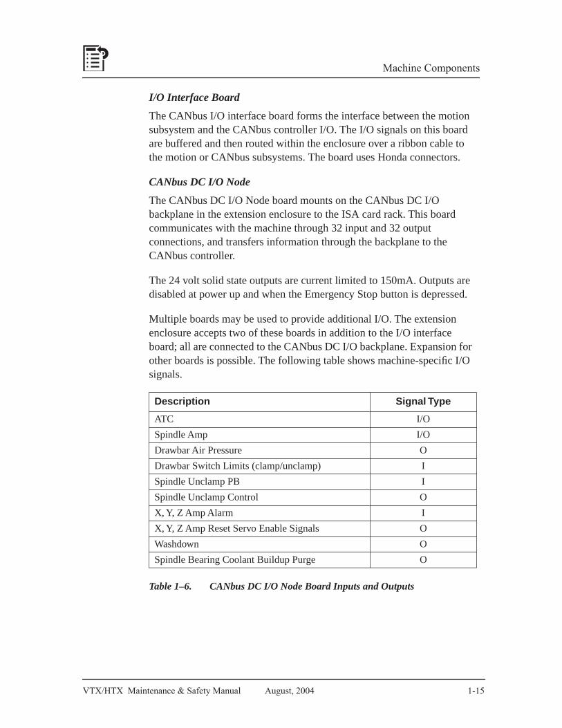
Multiple boards may be used to provide additional I/O. The extension enclosure accepts two of these boards in addition to the I/O interface board; all are connected to the CANbus DC I/O backplane. Expansion for other boards is possible. The following table shows machine-specific I/O signals.
Table 1–6. CANbus DC I/O Node Board Inputs and Outputs
Description Signal Type
ATC I/O
Spindle Amp I/O
Drawbar Air Pressure O
Drawbar Switch Limits (clamp/unclamp) I
Spindle Unclamp PB I
Spindle Unclamp Control O
X, Y, Z Amp Alarm I
X, Y, Z Amp Reset Servo Enable Signals O
Washdown O
Spindle Bearing Coolant Buildup Purge O

1-16 704-0211-211 VTX/HTX Maintenance & Safety Manual
Machine Components
Communication Ports
All communication ports are located on the Comm Port/Hour Meter/Light Switch panel assembly on machine control cabinet. The following connectors may be available:
Table 1–7. Communication Ports
The communication ports are typically arranged as follows:
Figure 1–4. Communication Port Assembly
Port Connector Type Use
PORTS 1 and 2 9-pin RS-232 C Serial Communications
Indexer 8-pin military Indexer
10-base T RJ45 Network (Ethernet)
Coax In/Out BNC Network (Ethernet)
10BASE-T PORT 1
PORT 2IN OUT
COAX
C
B DG
A F
E

VTX/HTX Maintenance & Safety Manual August, 2004 1-17
Machine Components
RS-232-C Serial Ports
The two RS-232-C serial ports (Port 1 and Port 2 in previous figure) can be used to connect peripherals to the machine. These ports may be addressed separately. The standard baud rates are software-selectable. Either port can be used as an output or input, depending upon the software.
The connector pin designated for each signal (RS-232-C) is shown below:
Figure 1–5. Male 9-Pin D-Type Connector
While the signals present at the serial ports conform to the RS-232-C standard, not all standard RS-232-C signals are available. Some peripheral devices may provide RS-232-C control signals that are not available at the ports described here. However, such devices can usually be adapted to these ports. In some cases, it may be necessary to add jumpers to the connector.
1 2 3 4 5
6 7 8 9

1-18 704-0211-211 VTX/HTX Maintenance & Safety Manual
Machine Components
Signals available at the serial ports are:
Table 1–8. RS-232-C Signals Available at Serial Ports
To connect a peripheral to the machine, fabricate an adapter cable. If a properly shielded low capacitance cable is used, cable lengths of up to 100 feet are permissible.
Be certain that you use the correct cabling before connecting the device to the machine. Consult the peripheral manual to determine whether the peripheral is a Data Terminal Equipment (DTE) or Data Communication Equipment (DCE) device. The Hurco machine is a DTE device, and in most cases, so is a personal computer. A printer may be either a DTE or DCE device.
COM 1/COM 2 Signal Name Signal on this Pin
1 Data Carrier Detect (DCD) Not used by the control.
2 Receive Data (RXD) Data received (by machine) in serial format from peripheral device.
3 Transmit Data (TXD) Data transmitted (by machine) to peripheral device in serial format.
4 Data Terminal Ready (DTR) Not used by the control.
5 Signal Ground (SG) Line establishing the common ground reference potential for all interface lines
6 Data Set Ready (DSR) Signal to notify printer that transmitter is ready for transmission.
7 Request to Send (RTS)
Line used by control to instruct periph-eral device to get ready to receive data. Data can be transmitted after the Clear-To-Send signal is received from con-nected peripheral device.
8 Clear to Send (CTS)Control line used by peripheral device to indicate that it is ready to receive data from machine.
9 Ring Indicator (RI) Signal indicates modem has received the ring of an incoming call.

VTX/HTX Maintenance & Safety Manual August, 2004 1-19
Machine Components
Indexer Port
Indexing signals are always present at the Indexer port, so there is no need to turn it on. It is the customer’s responsibility to provide a harness from the Indexer to the Indexer port. Before making this harness, see the machine’s
Parts Listings and Wiring Diagrams Manual
for the correct pin-outs.
Network Ports
The 10baseT (RJ45) and the two BNC connectors are used with the Ultinet option. This option requires an ethernet card, cabling from the ethernet card to the communications panel, V2.10 software or greater and an optikey diskette to enable the option.
Operator Control Console
Hurco VTX/HTX series machines come with a dual screen Ultimax 4 control console. Contact your full service distributor or Hurco for more information about features.
The dual screen Ultimax 4 console sits on a base-mounted pendant. Text is displayed on one screen of the console, and graphics on the other. A 3.5 in. floppy disk drive is located on the right side of the dual screen console.
For operating and programming information, refer to the
Getting Started Manual, Conversational Part Programming Manual
and the
NC Part Programming Manual
shipped with the machining center.

1-20 704-0211-211 VTX/HTX Maintenance & Safety Manual
Machine Components
An Ultimax 4 console is pictured below:
Figure 1–6. Ultimax 4 Control Console

VTX/HTX Maintenance & Safety Manual August, 2004 1-21
Machine Components
Flat Panel Node PCB
The CANbus Flat Panel Node PCB is an intelligent slave that processes the operator interface I/O functions related to the console. This printed circuit board is located in the Ultimax control console and has the following features:
• An 8 x 8 keyboard matrix for scanning, decoding and debouncing of keys
• Outputs to control 16 discrete LEDs and three 24-volt status lamps
• Emergency stop hardware contacts and software input
• Green “Run” LED and red system fail “Sysfail” LED
For operating and programming information, refer to the
Ultimax Getting Started, Conversational Part Programming and NC Part Programming
manuals shipped with the machine.
Coolant System
A flood coolant system is standard on each machining center. A washdown hose and nozzle to clean chips from inside the enclosure are also included.
Table 1–9. Coolant Capacity and Pump Rating
The flood coolant system cleans swarf from the cut and protects the part and tool. The system is self-contained. The operator can control the coolant system using console pushbuttons.
Tank Capacity Flood Pump RatingWash DownPump Rating
Machine Liters Gal. Liters/min. Gal./min. Liters/min Gal./min.
VTXU 350 92.5 60 16 60 16
HTX 580 153 60 16 60 16

1-22 704-0211-211 VTX/HTX Maintenance & Safety Manual
Machine Components
Pneumatic System The pneumatic system regulates the air valves that supply compressed air to machine systems, such as spindle blow out. Compressed air is used in the tool release and in ATC motion.
Important
A factory-set air pressure detecting switch monitors the air supply to the solenoid control valves. Do not tamper with this switch.
The Filter, Regulator and Lubricator (FRL) Unit is connected to the air manifold and meters lubricant into the pneumatic system. The FRL prevents moisture from contaminating the compressed air supply, promotes trouble-free operation of air cylinders and valves, and extends the service life of metal components that come in contact with the air stream.
Incoming air pressure can be adjusted using the knob on top of the filter assembly. For information about maintaining the FRL Unit, refer to the Lubrication section of the Machine Maintenance chapter in this manual.

VTX/HTX Maintenance & Safety Manual August, 2004 1-23
Machine Components
VTX Automatic Tool ChangerThe VTX machining center uses hydraulics, pneumatics, and switches to operate a tool pot, swing arm, and an ATC door to exchange tools between the ATC magazine and the machine spindle. The ATC is a random-pocket tool changer that tracks tools in the magazine using an ATC Map. All ATC operations require that the servo power is on, that the machine is calibrated, and that the ATC is at Home position. The table below lists tooling specifications:
Table 1–10. ATC Tool Specifications—VTXU
The basic sequence of operation, assuming that the magazine is positioned to the next tool required, is as follows:
1. The ATC door opens if the X and Y axes are at tool change position, the Z axis is at Height (refer to the following “ATC Diagnostics Screen, VTX” figure), and the spindle is oriented.
2. The tool pocket rotates from the Up position to the Down position.
3. The load arm rotates 60 degrees from the 0 degree position and simultaneously grasps the tool in the tool pocket and the tool in the spindle, if present.
4. The spindle unclamps the tool.
5. The load arm moves down, simultaneously pulling the tool from the tool pocket and the tool from the spindle, and rotates 180 degrees.
6. The load arm moves up and inserts the new tool into the spindle and the previous tool into the tool pocket, returning the load arm to the 60 degree position.
Machine Taper
Number of Tool
Pockets
Maximum Tool
Diameter
Maximum Tool Diameter
Adjacent Tool Pockets Empty
MaximumTool
Length
MaximumTool
Weight
mm in. mm in mm in kg lbs
VTXU 40 32 75 2.9 125 4.9 280 11.0 7 15

1-24 704-0211-211 VTX/HTX Maintenance & Safety Manual
Machine Components
7. The spindle clamps the tool in the spindle.
8. The load arm rotates 60 degrees back to the 0 degree position.
9. The tool pocket rotates back to the Up position.
10. The ATC door closes.
The ATC can be operated in Auto mode or in Manual mode using ATC Diagnostics.
ATC Diagnostics for VTX MachinesDisplay the ATC Diagnostics screen in Manual mode by selecting the TOOL IN SPINDLE softkey followed by the ATC DIAGNOSTICS softkey.
Figure 1–7. ATC Diagnostics Screen, VTX

VTX/HTX Maintenance & Safety Manual August, 2004 1-25
Machine Components
The ATC Diagnostics screen displays the status of inputs for the ATC.
Table 1–11. ATC Diagnostics Input Descriptions
Status Description
Spindle Orientation Indicates if the Spindle is Oriented or Not Oriented. Oriented is required for ATC to begin.
Spindle Clamp Indicates if the Spindle is clamped or unclamped.
ATC OK to Stop Indicates Off or On. On is set during Load Arm rotation and disables the Load Arm motor and enables the brake. Off should be set when Load Arm is at 0 degree or 60 degrees.
Tool Pocket Indicates Up or Down position. Up is required for ATC Status Home.
Load Arm Indicates 0 degree or 60 degrees position. 0 degree is required for ATC Status Home. Can-not move to 60 degrees unless ATC Door is Open, Tool Pocket is Down, Spindle is Oriented and Clamped.
Magazine Reference Indicates Reference Pos when the ATC calibra-tion sensor is detected.
Magazine In Position Indicates In Pos (1) or In Pos (2). In Pos (1) is required for ATC Status Home. In Pos (2) is active when magazine is rotating and not in position.
Magazine Lock VTX machines are not equipped with a Maga-zine Lock Pin. Status is for display only.
Magazine Position Indicates the current magazine position (note that this may not be the tool number).

1-26 704-0211-211 VTX/HTX Maintenance & Safety Manual
Machine Components
General Status Conditions
The following table indicates general status conditions:
Table 1–12. ATC Diagnostics Input Descriptions, General
Status Description
Start Pushbutton Indicates Off or On. On is displayed when the Start pushbutton is pressed.
SpindleUnclamp PB
Indicates Off or On. On is displayed when the Spindle Unclamp pushbutton is pressed.
MagazineRotate SW
Indicates the three settings for the Magazine Rotate switch, either CCW, Off, or CW. The magazine will rotate in the direction indicated until it is released back to Off.
Way Lube Level Indicates OK or Low Level. A Low Level alarm will not allow programs to start running.
Air Pressure Indicates OK or Low Pressure. OK is required to begin an ATC.
Tool CoolantSystem
Available with the Coolant Through Spindle (CTS) option. Indicates Filter OK and Pressure OK. Both are required for tool coolant operation.
Clamped w/o Tool Switch
This condition is not available. Indicates Off or On.
ATC Position Indicates Z At Height and X/Y at Position. Both inputs are required for ATC to begin.
ATC Status Indicates Home position. Home is required for ATC to begin.
ATC Door Indicates Closed or Open position. Closed is required for ATC Status Home.

VTX/HTX Maintenance & Safety Manual August, 2004 1-27
Machine Components
ATC Diagnostics Softkeys
There are three menus of softkeys for controlling the ATC operation. Pressing the PAGE softkey in each menu cycles the display to the next menu or to menu 1 from menu 3.
When all requirements for a softkey action are met, a prompt displays and the Cycle Start lamp flashes. Pressing Cycle Start executes the command. The Cycle Start lamp stops flashing during the execution of the command and is turned off when the command is completed.
Selecting another softkey before pressing the Cycle Start button cancels the pending command and stops the Cycle Start lamp flashing. If the requirements for a softkey action are not met, a message displays indicating why the action cannot be commanded.
Table 1–13. ATC Diagnostics Softkey Menu 1, VTX
Softkey Description
Orient Spindle Sets the command to orient the spindle. Oriented is required to begin an ATC cycle.
Tool PocketUp / Down
Sets the command to move the Tool Holder Down or Up. Each press of the softkey switches the com-mand between Down and Up.
Load Arm0 Degree /60 Degrees
Sets the command to move the Load Arm to 0 degree or 60 degrees. Tool Pocket must be Down and ATC Door Open before moving to 60 degrees. Each press of the softkey switches the command between 0 degree and 60 degrees.
Spindle Clamp /Unclamp
Sets the command to clamp or unclamp the spindle. Each press of the softkey switches the command between clamp and unclamp.
Exchange Arm Rotate
Sets the command to move the Exchange Arm down, rotate 180 degrees and up. Tool Pocket must be Down and ATC Door Open.
1-28 704-0211-211 VTX/HTX Maintenance & Safety Manual
Machine Components
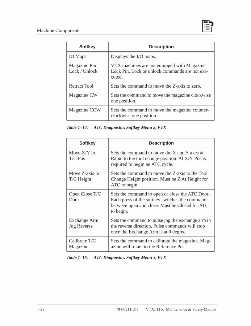
Table 1–14. ATC Diagnostics Softkey Menu 2, VTX
Table 1–15. ATC Diagnostics Softkey Menu 3, VTX
Softkey Description
IO Maps Displays the I/O maps.
Magazine Pin Lock / Unlock
VTX machines are not equipped with Magazine Lock Pin. Lock or unlock commands are not exe-cuted.
Retract Tool Sets the command to move the Z-axis to zero.
Magazine CW Sets the command to move the magazine clockwise one position.
Magazine CCW Sets the command to move the magazine counter-clockwise one position.
Softkey Description
Move X/Y toT/C Pos
Sets the command to move the X and Y axes at Rapid to the tool change position. At X/Y Pos is required to begin an ATC cycle.
Move Z-axis toT/C Height
Sets the command to move the Z-axis to the Tool Change Height position. Must be Z At Height for ATC to begin.
Open Close T/C Door
Sets the command to open or close the ATC Door. Each press of the softkey switches the command between open and close. Must be Closed for ATC to begin.
Exchange Arm Jog Reverse
Sets the command to pulse jog the exchange arm in the reverse direction. Pulse commands will stop once the Exchange Arm is at 0 degree.
Calibrate T/CMagazine
Sets the command to calibrate the magazine. Mag-azine will rotate to the Reference Pos.

VTX/HTX Maintenance & Safety Manual August, 2004 1-29
Machine Components
IO Maps for VTX MachinesSelecting the IO MAPS softkey displays a menu to select a display of the control’s input or output states. The outputs cannot be activated nor can the inputs be tested. Each of the softkeys identifies I/O boards in the control.
Displayed I/O maps include the input or output signal identifier list. The input or output signals are highlighted when the signal is activated or enabled. Refer to the machine’s Parts Listing and Wiring Diagram manual for schematics and harnesses that will identify the signals and boards.
Figure 1–8. I/O Status, IOIF and DCI/O #1

1-30 704-0211-211 VTX/HTX Maintenance & Safety Manual
Machine Components
Figure 1–9. I/O Status, DCI/O #2

VTX/HTX Maintenance & Safety Manual August, 2004 1-31
Machine Components
HTX Automatic Tool ChangerThe HTX machining center uses hydraulics, pneumatics, and switches to operate a tool pot, swing arm, and an ATC door to exchange tools between the ATC magazine and the spindle. The ATC is a random-pocket tool changer that tracks tools in the magazine using an ATC Map.
The the following table lists tooling specifications.
Table 1–16. ATC Tool Specifications—HTX500
All ATC operations require that the servo power is on, the machine is calibrated, and the ATC is at Home position. Refer to the following “ATC Diagnostics Screen — HTX” figure.
The basic sequence of operation, assuming that the magazine has positioned to the next tool required, is as follows:
1. The tool holder rotates 90 degrees from the 0 degree position to the 90 degree position and simultaneously the ATC door opens.
2. If the X, Y, and Z axes are at tool change position and the spindle is oriented, the exchange arm rotates 90 degrees from the 0 degree position to the 90 degree position and simultaneously grasps the tool in the tool holder and the tool in the spindle, if present.
3. The spindle unclamps the tool.
4. The exchange arm moves out, simultaneously pulling the tool from the tool holder and the tool from the spindle, the exchange arm rotates 180 degrees.
Machine Taper
Number of Tool
Pockets
Maximum Tool
Diameter
Maximum Tool Diameter
Adjacent Tool Pockets Empty
MaximumTool
Length
MaximumTool
Weight
mm in. mm in mm in kg lbs
HTX500 40 60 80 3.2 150 5.9 350 13.8 10 22

1-32 704-0211-211 VTX/HTX Maintenance & Safety Manual
Machine Components
5. The exchange arm moves in, inserting the new tool into the spindle and the removed tool into the tool holder. The exchange arm moves out and returns to the 90 degree position.
6. The spindle clamps the tool in the spindle.
7. The exchange arm rotates 90 degrees back to the 0 degree position.
8. The ATC door closes and the tool holder simultaneously rotates 90 degrees back to the 0 degree position.
The ATC can be operated in Auto mode or in Manual mode using ATC Diagnostics.
ATC Diagnostics for HTX MachinesDisplay the ATC Diagnostics screen in Manual Mode by selecting the TOOL IN SPINDLE softkey followed by the ATC DIAGNOSTICS softkey.
Figure 1–10. ATC Diagnostics Screen—HTX
VH08921.00.00

VTX/HTX Maintenance & Safety Manual August, 2004 1-33
Machine Components
Status Conditions
The ATC Diagnostics screen displays the status of inputs for the ATC.
Table 1–17. ATC Diagnostics Input Descriptions
Status Description
SpindleOrientation
Indicates if the Spindle is oriented or not oriented. Oriented is required for ATC to begin.
Spindle Clamp Indicates if the Spindle is clamped or unclamped.
Tool Holder Indicates 0 or 90 degree position. 0 degrees is required for ATC Status Home.
Exchange Arm Indicates 0 or 90 degree position. 0 degrees is required for ATC Status Home.
Magazine Position Indicates the current magazine position (note that this may not be the tool number).
Magazine InPosition
Indicates In Pos (1) or In Pos (2). In Pos (1) is required for ATC Status Home. In Pos (2) is active when magazine is rotating and not in position.
MagazineReference
Indicates Reference Pos when the ATC calibration sensor is detected.
Magazine Pin Indicates Locked or Unlocked position. Locked is required for ATC Status Home.
Z-axis Position Indicates At Zero position.
ATC Axis Position Indicates At X, At Y, and At Z positions. All three are required for ATC to begin.
ATC Status Indicates Home position. Home is required for ATC to begin.
ATC Door Indicates Closed or Open position. Closed is required for ATC Status Home.
ATC Calibrated Indicates Yes or No for ATC calibration
Tool in Spindle Indicates the tool number in the spindle.

1-34 704-0211-211 VTX/HTX Maintenance & Safety Manual
Machine Components
ATC Diagnostics Softkeys
There are three menus of softkeys for controlling the ATC operation. Pressing the MORE softkey in each menu cycles the display to the next menu or to menu 1 from menu 3.
When all requirements for a softkey action are met, a prompt displays and the cycle start lamp flashes. Pressing Cycle Start executes the command. The cycle start lamp stops flashing during the execution of the command and is turned off when the command is completed.
Selecting another softkey before pressing the Cycle Start button cancels the pending command and stops the cycle start lamp flashing. If the requirements for a softkey action are not met, a message displays indicating why the action cannot be commanded.
Table 1–18. ATC Diagnostics Softkey Menu 1
Status Description
Orient Spindle Sets the command to orient the spindle. Oriented is required to begin an ATC cycle.
ATC DoorOpen / Close
Sets the command to open or close the ATC Door. Each press of the softkey switches the command between open and close. Must be Closed for ATC to begin.
Tool Holder0 Degree /90 Degrees
Sets the command to move the Tool Holder to 0 degree or 90 degrees. Each press of the softkey switches the command between 0 degree and 90 degrees.
Exchange Arm0 Degree /90 Degrees
Sets the command to move the Exchange Arm to 0 degree or 90 degrees. Tool Holder must be at 90 degrees and ATC Door Open. Once rotated to 90 degrees, the Exchange Arm must be rotated 180 degrees or jog reversed back to 0 degree.
Spindle Clamp / Unclamp
Sets the command to clamp or unclamp the spindle. Each press of the softkey switches the command between clamp and unclamp.
Exchange Arm 180 Degrees
Sets the command to move the Exchange Arm out, rotate 180 degrees and in. Tool Holder must be at 90 degrees and ATC Door Open. Must be at 0 degree for ATC to begin.

VTX/HTX Maintenance & Safety Manual August, 2004 1-35
Machine Components
Table 1–19. ATC Diagnostics Softkey Menu 2
Table 1–20. ATC Diagnostics Softkey Menu 3
Status Description
Move Axes to TC Position
Sets the command to move the axes at Rapid to the tool change position. At X, At Y, and At Z are all required to begin an ATC cycle.
Move Z-axis to Zero Position
Sets the command to move the Z-axis to the Zero position.
Magazine CW Sets the command to move the magazine clockwise one position.
Magazine CCW Sets the command to move the magazine counter-clockwise one position.
Calibrate T/C Magazine
Sets the command to calibrate the magazine. Magazine will rotate to the Reference Pos.
Status Description
IO Maps Displays the I/O maps.
Exchange Arm Jog Reverse
Sets the command to pulse jog the exchange arm in the reverse direction. Once initiated, continue selecting until the Exchange Arm is at 0 or 90 degrees.
1-36 704-0211-211 VTX/HTX Maintenance & Safety Manual
Machine Components
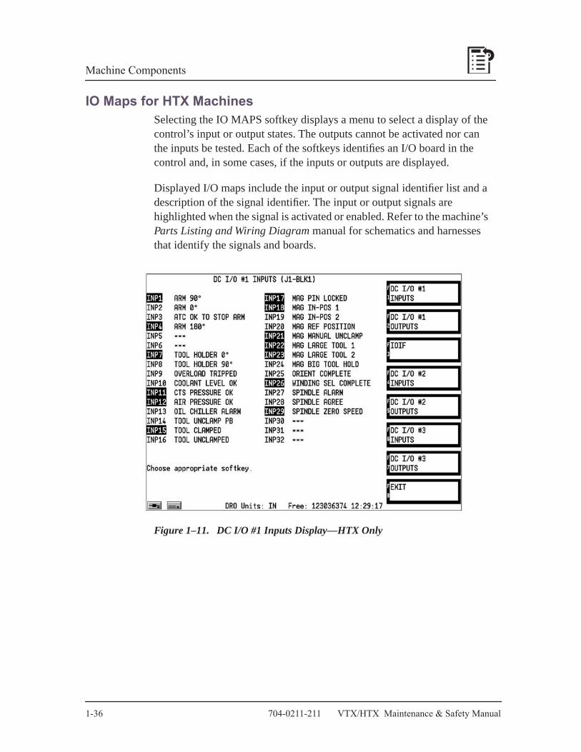
IO Maps for HTX MachinesSelecting the IO MAPS softkey displays a menu to select a display of the control’s input or output states. The outputs cannot be activated nor can the inputs be tested. Each of the softkeys identifies an I/O board in the control and, in some cases, if the inputs or outputs are displayed.
Displayed I/O maps include the input or output signal identifier list and a description of the signal identifier. The input or output signals are highlighted when the signal is activated or enabled. Refer to the machine’s Parts Listing and Wiring Diagram manual for schematics and harnesses that identify the signals and boards.
Figure 1–11. DC I/O #1 Inputs Display—HTX Only

VTX/HTX Maintenance & Safety Manual August, 2004 1-37
Machine Components
Figure 1–12. DC I/O #1 Outputs Display—HTX Only
Figure 1–13. IOIF Display—HTX Only

1-38 704-0211-211 VTX/HTX Maintenance & Safety Manual
Machine Components
Figure 1–14. DC I/O #2 Inputs Display—HTX Only
Figure 1–15. DC I/O #2 Outputs Display—HTX Only

VTX/HTX Maintenance & Safety Manual August, 2004 1-39
Machine Components
Figure 1–16. DC I/O #3 Inputs Display—HTX Only
Figure 1–17. DC I/O #3 Outputs Display—HTX Only

1-40 704-0211-211 VTX/HTX Maintenance & Safety Manual
Machine Components
Machine DiagnosticsA status of control states can be displayed from Manual mode by selecting the TOOL IN SPINDLE softkey followed by the MACHINE DIAGNOSTICS softkey.
Figure 1–18. Machine Diagnostics Display
VTX/HTX Maintenance & Safety Manual August, 2004 1-41
Machine Components
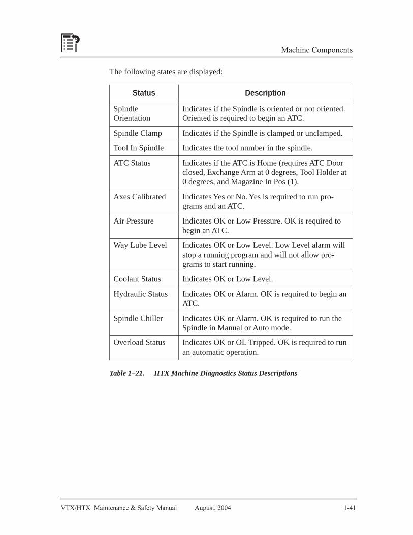
The following states are displayed:
Table 1–21. HTX Machine Diagnostics Status Descriptions
Status Description
SpindleOrientation
Indicates if the Spindle is oriented or not oriented. Oriented is required to begin an ATC.
Spindle Clamp Indicates if the Spindle is clamped or unclamped.
Tool In Spindle Indicates the tool number in the spindle.
ATC Status Indicates if the ATC is Home (requires ATC Door closed, Exchange Arm at 0 degrees, Tool Holder at 0 degrees, and Magazine In Pos (1).
Axes Calibrated Indicates Yes or No. Yes is required to run pro-grams and an ATC.
Air Pressure Indicates OK or Low Pressure. OK is required to begin an ATC.
Way Lube Level Indicates OK or Low Level. Low Level alarm will stop a running program and will not allow pro-grams to start running.
Coolant Status Indicates OK or Low Level.
Hydraulic Status Indicates OK or Alarm. OK is required to begin an ATC.
Spindle Chiller Indicates OK or Alarm. OK is required to run the Spindle in Manual or Auto mode.
Overload Status Indicates OK or OL Tripped. OK is required to run an automatic operation.

1-42 704-0211-211 VTX/HTX Maintenance & Safety Manual
Machine Components
Machine ParametersIn Manual mode, selecting the MACHINE PARAMETERS softkey displays a list of user-configurable parameters. There are three pages of Machine Parameters that can be changed by the operator. Each page lists a description of the parameter, the range of values that can be set for the parameter, and the current value. The values shown on the following figures are the default factory settings.
Caution
The machine, part, and/or tool may be damaged if parameters are changed without understanding the machine operation that may be affected by the change.
Figure 1–19. Machine Parameters, Page 1

VTX/HTX Maintenance & Safety Manual August, 2004 1-43
Machine Components
Warm-up Cycle Time, Warm-up Spindle Speed 1, 2, and 3, and Warm-up Axis Feed Rate
The first five parameters listed on Page 1 allow the operator to configure the machine’s warm-up cycle. Warm Up Machine is a softkey selection in Manual mode. During Warm Up Machine, the spindle rpm is at the Warm-up Spindle Speed 1 RPM for the Warm-up Cycle Time while the X and Y axes move diagonally from corner to corner at the Warm-up Axis Feed Rate in the units indicated.
Note
The Z-axis is at zero and does not move during the Warm Up Machine cycle. The Tool In Spindle setting must be 0 before begin-ning Warm Up Machine.
After the Warm-up Cycle time expires, the spindle speed changes to the Warm-up Spindle Speed 2 RPM. Axis motion continues and will run until the Warm-up Cycle Time expires. This is repeated a third and final time at the Warm-up Spindle Speed 3 RPM.
Note
A negative value for Warm-up Spindle Speed will turn the spindle counterclockwise; a positive value will turn the spindle clockwise.
The Warm Up Machine cycle default settings run each step for 300 seconds at the maximum feed rate. Step 1 turns the spindle clockwise at 100 rpm, step 2 turns the spindle counterclockwise at 1000 rpm, and step 3 turns the spindle clockwise at 3000 rpm.

1-44 704-0211-211 VTX/HTX Maintenance & Safety Manual
Machine Components
Coolant Delay Time (sec)The Coolant Delay Time parameter pauses the running part program for the indicated time whenever the program enables the primary or secondary coolant. Set the Coolant Delay Time parameter to pause the program long enough to allow the coolant to pump from the coolant tank to the head-mounted nozzles before the tool enters the work piece.
The default setting for Coolant Delay Time is 0 seconds.
Pulsating Washdown EnablePulsating Washdown Enable is not functional for VTX and HTX machines.
The default setting for Pulsating Washdown Enable is 0.
Alt Washdown Dwell (0.01 sec) Alternating Washdown Dwell is not functional for VTX and HTX machines.
The default setting for Alternating Washdown Dwell is 500 (or 5 seconds).
Alt Dwell Lt Side (0.01 sec)The Alternating Dwell Left Side is not functional for VTX and HTX machines.
The default setting for Alternating Dwell Left Side is 0 seconds.
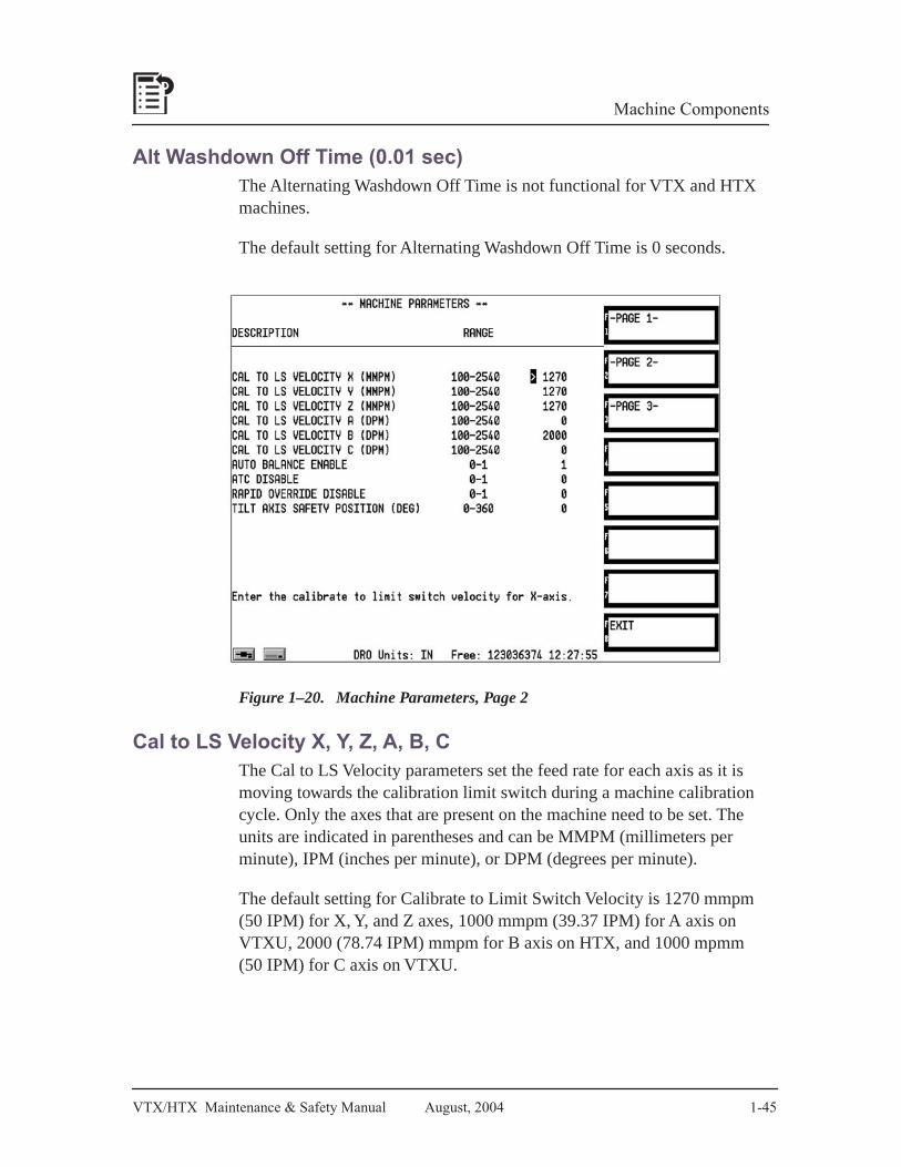
VTX/HTX Maintenance & Safety Manual August, 2004 1-45
Machine Components
Alt Washdown Off Time (0.01 sec)The Alternating Washdown Off Time is not functional for VTX and HTX machines.
The default setting for Alternating Washdown Off Time is 0 seconds.
Figure 1–20. Machine Parameters, Page 2
Cal to LS Velocity X, Y, Z, A, B, CThe Cal to LS Velocity parameters set the feed rate for each axis as it is moving towards the calibration limit switch during a machine calibration cycle. Only the axes that are present on the machine need to be set. The units are indicated in parentheses and can be MMPM (millimeters per minute), IPM (inches per minute), or DPM (degrees per minute).
The default setting for Calibrate to Limit Switch Velocity is 1270 mmpm (50 IPM) for X, Y, and Z axes, 1000 mmpm (39.37 IPM) for A axis on VTXU, 2000 (78.74 IPM) mmpm for B axis on HTX, and 1000 mpmm (50 IPM) for C axis on VTXU.

1-46 704-0211-211 VTX/HTX Maintenance & Safety Manual
Machine Components
Auto Balance EnableSet the Auto Balance Enable parameter to 1 for all normal operating modes of the control. Only a trained technician performing diagnostic tuning of the servo amplifiers should set the Auto Balance Enable value to 0.
The default setting for Auto Balance Enable is 1.
ATC DisableThe ATC Disable parameter allows the user to completely disable all automatic tool change functions. Setting the ATC Disable parameter to 1 disables the Auto Tool Change button (for performing tool changes in Manual mode or Tool Setup) and the Auto Tool Change in Auto mode button (for running programs). With ATC Disable set to 1, all tools will have to be inserted and removed manually using the Spindle Clamp/Unclamp button mounted on the head.
Caution
When ATC is disabled, the Control assumes that the ATC is in a safe position to allow normal X, Y, and Z axis movement. Input status for the ATC at home position will not be checked. Failure to ensure that the ATC is in a safe position may result in machine damage.
The default setting for ATC Disable is 0.
Rapid Override DisableThe Rapid Override Disable parameter allows the user to enable or disable the Rapid Override potentiometer on the console. Rapid Override Disable set to 1 disables the Rapid Override potentiometer so that all rapid movements in an automatic operation will be at the programmed setting. Rapid Override Disable set to 0 enables the Rapid Override so that rapid movements in an automatic operation may be adjusted slower than the programmed setting.
The default setting for Rapid Override Disable is 0.

VTX/HTX Maintenance & Safety Manual August, 2004 1-47
Machine Components
Tilt Axis Safety Position (deg)The Tilt Axis Safety Position parameter sets the position for the tilt axis during an ATC if either the Move to Safe Pos During TC parameter is set to Yes (for Auto Run mode) or the Move to Safety Pos Manual Mode ATC parameter (for Manual or Input modes) is set to 1. After the Z retracts before the ATC, the tilt axis moves to the position indicated in degrees. After the ATC, the tilt axis returns to the original position.
The Tilt Axis Safety Position parameter is functional only for VTXU machines. The default setting for Tilt Axis Safety Positioning (deg) is 0.
Figure 1–21. Machine Parameters, Page 3
Aux Output 1, 2, 3, 4 Confirmation EnableAux Output 1, 2, 3, 4 Confirmation Enable set to 1 enables a confirmation signal for completion of each Auxiliary M-code Output. The program pauses until the confirmation signal is detected. A setting of 0 will not require a confirmation signal and will not pause the program during the Auxiliary M-code Output.
The default setting for each Auxiliary Output Confirmation Enable is 0.

1-48 704-0211-211 VTX/HTX Maintenance & Safety Manual
Machine Components
Disable Aux Out 1, 2, 3, 4 During InterruptDisable Aux Output 1, 2, 3, 4 During Interrupt set to 1 disables each Auxiliary M-code Output when an Interrupt cycle is selected during Auto Run mode. Upon return to Auto Run mode, the Auxiliary M-code Output will automatically be re-enabled. However, if another mode is selected then the Auxiliary M-code Output will remain disabled until activated again in Auto Run mode. A setting of 0 will leave the Auxiliary M-code Output enabled when an Interrupt cycle is selected during Auto Run mode. It will remain enabled after exit from Interrupt cycle, even if to a different mode than Auto Run.
The default setting for Disable Auxiliary Output During Interrupt is 0.
SSM Mouse Scaling FactorThe SSM Mouse Scaling Factor parameter is not functional for VTX and HTX machines.
The default setting for SSM Mouse Scaling Factor is 0.450
Move to Safety Pos Manual Mode ATCWhen the Manual Mode ATC operations parameter is set to 0 for an ATC command, the Z axis moves to tool change height and the ATC is completed at the current X and Y axis position. If this parameter is set to 1 then the Z axis moves at rapid to zero, the X and Y axes move at rapid to the table safety position (consult with Hurco service engineer to change this position), the Z axis moves to tool change height, and the ATC is completed. After the ATC completes, the Z axis moves to zero and the X and Y axes move at rapid back to the previous X and Y position.
Note
The Move to Safety Position for Manual Mode ATC only applies to Manual mode. ATC operations in Auto Mode are not affected by this parameter. To move the table to the safety position during an ATC in Auto Mode, set the Move to Safe Pos During TC from Program Parameters in Input.
The default setting for Move to Safety Pos Manual Mode ATC is 0.

VTX/HTX Maintenance & Safety Manual August, 2004 1-49
Machine Components
Automatic Pallet Changer System The Automatic Pallet Changer (APC) system is standard on HTX machining centers only. Equipped with two pallets, the APC provides the ability to simultaneously setup a job on one pallet while a job is machined on the other pallet.
The APC is hydraulically controlled by solenoids, switches, and software to permit pallet switching automatically within the part program. In addition, manual controls are also provided. The APC has two pallets that are numbered one and two, respectively.
The basic sequence of operation of the APC is as follows:
1. The APC Table must be squared before any motion can occur.
2. The APC Pin is unlocked.
3. The APC Clamp is disabled.
4. The APC Table is raised hydraulically.
5. The APC Table rotates 180 degrees by engaging hydraulic solenoids to rotate in the proper direction.
Important
The APC Table does not rotate through 360 degrees. The APC table returns to the previous position by rotating in the opposite direction.
6. The APC Table is lowered hydraulically.
7. The APC Clamp is enabled.
8. The APC Pin is locked.
Pallet Changer Solenoids and AdjustmentThe APC solenoids are located at the bottom front of the enclosure beneath the remote APC Panel.
1. The top solenoid controls the speed adjustment. The left-hand adjustment is for high-speed rotation and the right-hand adjustment is for low-speed rotation. The high-speed rotation occurs from the beginning of the rotation until a proximity switch detects the Decel input. Then the low-speed rotation occurs until the Pallet is in position to be lowered. Adjust for smooth rotation into position.

1-50 704-0211-211 VTX/HTX Maintenance & Safety Manual
Machine Components
2. The second level of solenoids is for rotating to Position 1 (left-hand solenoid) and Position 2 (right-hand solenoid).
3. The third level of solenoids is for raising (left-hand solenoid) and lowering (right-hand solenoid) the APC table.
4. The fourth level of solenoids is for the APC Pin Lock.
5. The fifth level of solenoids is for the APC Clamp.
Squaring the APC TableBefore any APC operation can occur, the APC Table must be squared. The APC Table is driven by a servo motor and uses encoder feedback for positioning and a proximity switch for the home position. During machine calibration, the APC Table is not automatically squared. Squaring the APC Table requires selecting the softkey in Pallet Changer Diagnostics.
In Pallet Changer Diagnostics, selecting the SQUARE PALLET FOR ROTATION softkey followed by pressing the Cycle Start button will rotate the APC Table into the proper position for the pallet exchange cycle. If the B-axis is jogged away from the squared position, selecting the SQUARE PALLET FOR ROTATION softkey rotates the table at the maximum rpm back to the squared location.
Manual Pallet Changer OperationThe remote APC Panel (see the Remote APC Panel figure) is located on the front of the enclosure below the front enclosure doors. The APC Panel may be used to manually raise and lower the APC Table and to rotate between Position 1 and Position 2.
Figure 1–22. Remote APC Panel
1 1 20
VTX/HTX Maintenance & Safety Manual August, 2004 1-51
Machine Components
The basic function of each of the buttons, left to right:
• Emergency Stop — Disables all axis servo drives. Removes power to the hydraulic pump that moves the pallet changer. All pallet movement stops.
• Cycle Start — Initiates a selected operation that runs until the operation is completed. The Cycle Start lamp flashes while the operation is pending, the lamp is steady when the operation is in process, and the lamp is off when the operation is complete.
• Cycle Stop — Cancels any pending operation (if the Cycle Start lamp is flashing, it will turn the lamp off). Pressing Cycle Start after an operation is canceled with Cycle Stop action results in no APC motion.
• Workzone Confirmation Or Ready To Rotate — Used for automatic operation only (see Automatic Pallet Changer Operation section).
• Hydraulic Lift — Issues a command to either raise or lower the APC Table. If the table is in the lowered position the table raises and if in the raised position the table lowers. Pressing Hydraulic Lift illuminates the Hydraulic Lift lamp and causes the Cycle Start lamp to flash. A Cycle Start action is required to begin lifting or lowering the APC Table. The Hydraulic Lift lamp will be off when the raise or lower operation is completed or is canceled by a Cycle Stop action.
• If the APC Table is in the Down position, the Ultimax console will display the message, “APC unit will raise.”
• If the APC Table is in the Up position, the Ultimax console will display the message, “APC unit will lower.”
• APC Table Rotate To Position 1— If the external pallet is Table 1 then press this button to initiate the command to rotate the APC Table to place Table 1 into the machining area. The APC Table Rotate To Position 1 button functions only with the APC Table in the Up position. Pressing the APC Table Rotate To Position 1 button illuminates its lamp and causes the Cycle Start lamp to flash. The Ultimax console displays the message, “APC unit will rotate to position 1.” A Cycle Start action is required to begin the rotation of the APC Table. The APC Table Rotate to Position 1 lamp turns off

1-52 704-0211-211 VTX/HTX Maintenance & Safety Manual
Machine Components
when the operation is completed or the rotation is canceled by a Cycle Stop action.
• APC Table Rotate To Position 2— If the external pallet is Table 2 then press this button to initiate the command to rotate the APC Table to place Table 2 into the machining area. The APC Table Rotate to Position 2 button functions only with the APC Table in the Up position. Pressing the APC Table Rotate To Position 2 button illuminates its lamp and causes the Cycle Start lamp to flash. The Ultimax console displays the message, “APC unit will rotate to position 2.” A Cycle Start action is required to begin the rotation of the APC Table. The APC Table Rotate to Position 2 lamp turns off when the operation is completed or the rotation is canceled by a Cycle Stop action.
Note
When the Hydraulic Lift or either of the APC Table Rotate buttons are illuminated and the operation is waiting for a Cycle Start action, the Ultimax console Start Cycle button also flashes. Pressing the Ulti-max console Start Cycle button cancels the pending request and turns off the illuminated button’s lamp.

VTX/HTX Maintenance & Safety Manual August, 2004 1-53
Machine Components
Example of Manual Pallet Changer Operation
This example assumes that the APC Table has position 1 external or away from the machining area.
Important
Before initiating a manual APC operation:
• The Ultimax Control must be in Manual mode
• The machine must be calibrated
• Servo power must be on
• The ATC must be in Home position
• The Z-axis must be at zero
• Hydraulic Pressure must be OK
• The front enclosure doors must be closed
• The APC Table must be squared
Initiate a manual APC operation as follows:
1. Press the Hydraulic Lift button — the button lamp lights and the Cycle Start lamp flashes.
2. Press the Cycle Start button — the APC Table raises and the Cycle Start lamp stops flashing. When the APC Table is in the Up position, both the Cycle Start and the Hydraulic Lift lamps turn off.
3. Press the APC Table Rotate To Position 1 button — the button lamp lights and the Cycle Start lamp flashes.
4. Press the Cycle Start button — the APC Table begins a 180 degree high-speed rotation followed by low-speed rotation into position. The Cycle Start lamp stops flashing. When the APC Table is finished rotating, both the Cycle Start and the APC Table Rotate to Position 1 lamps turn off.
5. Press the Hydraulic Lift button — the button lamp lights and the Cycle Start lamp flashes.
6. Press the Cycle Start button — the APC Table lowers and the Cycle Start lamp stops flashing. When the APC Table is in the Down position, both the Cycle Start and the Hydraulic Lift lamps turn off.

1-54 704-0211-211 VTX/HTX Maintenance & Safety Manual
Machine Components
Manual APC Table RotationNear the front of the APC Table is a Manual Table Release Lever. This lever provides the input for the APC Pin Lock. To manually rotate the table without using the remote APC Panel, pull the Release Lever out. This allows the APC Table to be rotated by hand for part setup. After rotating the APC Table, the arrows on the Pallet must be aligned with the arrows on the APC Table’s platform before executing a pallet exchange.
Note
The APC Table must be in Down position before using the Manual Table Release Lever to rotate the table manually.
Caution
Failure to align arrows prior to executing a pallet exchange can result in the APC Table not positioning correctly in the machining area.

VTX/HTX Maintenance & Safety Manual August, 2004 1-55
Machine Components
Automatic Pallet Changer OperationThe APC Table can be operated in Auto mode within a Conversational or NC part program. M-code M51 is defined to initiate a complete APC cycle (see basic sequence of operation) for HTX machines only. Using M51 does not require indicating whether Position 1 or 2 is in the machining area or setup area but will perform a full APC cycle.
To program an M51 operation within a Conversational program, select the MISCELLANEOUS softkey in Part Programming of Input mode followed by the MACHINE FUNCTION softkey to display the Machine Function Display.
Figure 1–23. Machine Function Display

1-56 704-0211-211 VTX/HTX Maintenance & Safety Manual
Machine Components
Important
The front enclosure doors must be closed and the Workzone Confirmation button pressed before the M51 will initiate the APC cycle. This indicates to the program that the setup of the next workpiece is complete and ready for the machining area.
If the front enclosure doors are open when the M51 is requested, then the program will be in a Feed Hold state with a message to close the front enclosure doors displayed. Close the doors and press the Workzone Confirmation button to continue the part program.
If the Workzone Confirmation button has not been pressed when the M51 is requested then the program will be in a Feed Hold state with the following message displayed, “Pallet setup confirmation required to cycle pallet changer.” Press the Workzone Confirmation button and the Cycle Start button on the remote APC Panel to continue the program.
Note
Pressing Feed Hold during an APC cycle will stop the cycle. Releas-ing Feed Hold will resume the cycle. However, Feed Hold followed by Spindle Off (or the Stop Cycle button) during an APC cycle will abort the program and the APC cycle. The APC must be returned to the home position using the Pallet Changer Diagnostics before an Auto program can be run again.

VTX/HTX Maintenance & Safety Manual August, 2004 1-57
Machine Components
Pallet Changer DiagnosticsThe Pallet Changer Diagnostics screen displays after selecting the TOOL IN SPINDLE softkey on the Ultimax console while in Manual mode.
Figure 1–24. Pallet Changer Diagnostics Screen
V08923.00.00

1-58 704-0211-211 VTX/HTX Maintenance & Safety Manual
Machine Components
APC Diagnostics Softkeys
Pallet Changer Diagnostics softkeys are not functional unless servo power is on and the machine has been calibrated. Each softkey flashes the Start Cycle button on the Ultimax console if all conditions are met for the requested command. Pressing the Start Cycle button initiates the command and the Start Cycle lamp lights during the execution of the command. The Start Cycle lamp is turned off when the command is complete.
Table 1–22. Pallet Changer Diagnostics Softkey Descriptions
Softkey Description
Move Z Axis to Zero Position
Sets the command to move the Z-axis to the zero position.
Square Pallet for Rotation
Sets the command to square the pallet.
Cycle Pallet Changer
Sets the command to complete a full rotation of the APC Table (all eight steps of the basic sequence of operation).
Raise Pallet Changer
Sets the command to lift the APC Table to the Up position. The APC Table must be squared and the APC Table must not be Up.
Rotate APC to Position 1
Sets the command to rotate the APC Table to place Position 1 inside the machining area. The APC Table must be squared and Position 1 must not be in the machining area.
Rotate APC to Position 2
Sets the command to rotate the APC Table to place Position 2 inside the machining area. The APC Table must be squared and Position 2 must not be in the machining area.
Lower Pallet Changer
Sets the command to lower the APC Table to the Down position. The APC Table must be squared and the Table must not be Down.

VTX/HTX Maintenance & Safety Manual August, 2004 1-59
Machine Components
Status Conditions
The Pallet Changer Diagnostics screen also displays the status of inputs for the APC system (Table 1-22).
Table 1–23. Pallet Changer Diagnostics Status Descriptions
Status Description
APC Position Indicates whether the APC Table is in the Up or Down position.
Pallet in Machine Indicates whether the APC Table Position 1 or 2 is in the machining area.
APC Pin Indicates whether the APC Pin is Locked or Unlocked. The APC Pin must Unlock before the APC Table can be lifted and rotated and Locked to complete the cycle.
APC Decel Sw Indicates whether the Position 1 or 2 switch was seen during rotation. This switch enables low-speed rotation before the APC Table completes the 180 degree rotation.
APC Reference Indicates whether the Manual Table Release Lever is in the Reference Pos or has been retracted. The Manual Table Release Lever must be at Reference Pos to begin an APC cycle.
Hydraulic Status Indicates either OK or Alarm. Must be OK to begin an APC cycle.
Z-Axis Position Indicates if the Z-axis is At Zero (calibration point). Must be At Zero to begin an APC cycle.
ATC Status Indicates if the ATC is Home. Must be Home to begin an APC cycle.
Pallet Status Indicates Pallet Squared. Must be Pallet Squared to begin an APC cycle.

1-60 704-0211-211 VTX/HTX Maintenance & Safety Manual
Machine Components
This Page Intentionally Left Blank.

Chapter 2
VTX/HTX Maintenance & Safety Manual August, 2004 2-1
Machine Standards
European Community Machine Safety Standards
The information in this section complies with documentation requirements of the European Community’s machine safety standards.
Directives
These directives apply to all machining centers sold in Europe:
• European Machinery Directive 98/37/EC
• Electromagnetic Compatibility Directive 89/336/EEC(amended by 91/263/EEC and 92/31/EEC)
• European Low Voltage Directive 73/23/EEC(amended by 93/68/EEC)
Harmonized Standards
These standards apply to all machining centers sold in Europe:
Safety
EMC (Electromagnetic Compatibility)
Other Standards
• BS 5378 Parts 1 and 3
• EN 292-1 • EN 292-2• EN 294 • EN 349• EN 418 • EN 953• EN 954-1 • EN 60204-1
• EN 50081-2 • EN 50082-2

2-2 704-0211-211 VTX/HTX Maintenance & Safety Manual
Machine Standards
Safe Installation of Guarding System and Machine
Inspect the machining center to ensure that all parts are included and intact.
The owner is responsible for proper site preparation before the machine is installed. A Hurco Field Service Engineer must install the machine in the prepared location. This location must not subject the machine to uncontrolled cabinet temperatures or unfavorable work environment conditions that could cause electronic component failure.
If the owner decides later to move the machining center from its installed location, it is recommended that the owner call Hurco for assistance.
Warning
Improper moving of the machine may result in personal injury or damage to the machine.
Guarding System
Each machining center has a self-contained guarding system. Inspect the machine to ensure the guarding system is intact.
• The chip doors on the front of the machine lock during Automatic Run Mode to prevent access to the moving parts of the machine.
• The guards on each side of the machine are either movable or fixed. The movable guards can be opened to access the inside of the machine. A special key is required to open a fixed guard.
Machine
Check these items before the machine is installed:
Foundation Conditions
The foundation must be able to support the weight of the machining center, and should be constructed of continuous concrete (reinforced concrete is best). The thickness and consistency of the concrete must be compatible with industry standards for supporting the machine’s weight.
VTX/HTX Maintenance & Safety Manual August, 2004 2-3
Machine Standards
Actual requirements will depend upon the physical properties of underlying soil. Friction pads or machine anchors may be required to assure optimal machine performance.
Electrical Service Requirements
Follow all requirements below to help ensure personnel safety and to prevent equipment damage.
Warning
Always disconnect machine power before working with electrical connections.
Connecting Electrical Service
Observe the following guidelines when connecting electrical service:
• On-site wiring must comply with all established directives and standards.
• Dedicated, grounded 3-phase AC power is required to prevent high and/or low voltages, spikes, surges, and high frequency noise caused by inductive loads.
• The AC power source must match the voltage specifications listed on the machine’s data plate.
• Wiring to the machine must be capable of supplying continuous specified amperage.
• Failure to provide the required power parameters may affect machine safety, performance and warranty.
• A Hurco Certified Service Engineer must supervise final electrical connections to the machining center.
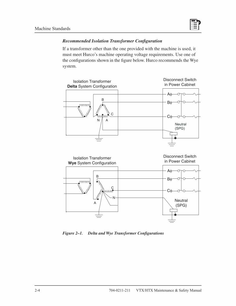
2-4 704-0211-211 VTX/HTX Maintenance & Safety Manual
Machine Standards
Recommended Isolation Transformer Configuration
If a transformer other than the one provided with the machine is used, it must meet Hurco’s machine operating voltage requirements. Use one of the configurations shown in the figure below. Hurco recommends the Wye system.
Figure 2–1. Delta and Wye Transformer Configurations
Isolation TransformerDelta System Configuration
Disconnect Switchin Power Cabinet
B
C
AN
Aφ
Bφ
Cφ
Isolation TransformerWye System Configuration
Disconnect Switchin Power Cabinet
Neutral(SPG)
C
A
Aφ
Bφ
Cφ
N
B

VTX/HTX Maintenance & Safety Manual August, 2004 2-5
Machine Standards
Grounding Equipment
The machine’s electrical and electronic control systems are interconnected, terminating at the Protective Earth (PE) or ground point.
• The ground point must be properly connected to the ground circuit of the AC power source. The ground point is located inside the machine’s power cabinet.
• The ground point provides only one conducting path between the machine and external ground, preventing an unwanted ground loop (ground differential voltage).
Compressed Air Requirements
A continuous supply of clean and dry air is essential for proper machine operation, and must be connected to the machine as described here.
Compressed Air Specification
Compressed air must conform to the specification: 5 CFM at 80-100 psi or 0.14 m
3
/min at 5.5 to 7.0 bar.
Connecting Compressed Air
The air supply line must meet these requirements:
• An NPT pipefitting must connect the air supply line to the machine.
• A regulator valve must be installed to control the air pressure into the machine.
• A factory-set pressure switch must be installed to shut off control voltages if the air pressure falls below the pre-set level.
• A minimum 1.27 cm diameter (1/2 inch, trade size) pipe, or an equivalent 1.99 cm (7/8 inch) diameter air hose supply line is required to provide adequate air volume.
• A drip leg should be installed in the line ahead of the filter/regulator assembly. The drip leg will help remove moisture accumulation in the supply, making the filter last longer.
• Quick coupler type fittings should not be used at the connection to the air filter/regulator, or within the supply line to the machine.

2-6 704-0211-211 VTX/HTX Maintenance & Safety Manual
Machine Standards
Anti-Vibration Mountings
Anti-vibration mountings, consisting of a spring-mounted ball bearing, are attached to each machine. Loose springs and balls are signs of excessive vibration.
Check the mountings before uncrating the machine to ensure that the machine has been handled properly prior to its arrival. Continue to inspect the mountings on a regular basis.
Initial Test and Examination
Follow the instructions below for performing the initial test and examination of the machine and its guarding system.
Contact your Hurco Distributor to arrange for a Hurco Service Engineer to perform the final machine setup. Complete these procedures prior to the Service Engineer’s arrival:
1. Provide utilities to the machine.
2. Check all machine lubrication levels.
3. Place the flood coolant tank, tubing, and coolant pump motor near the machine base.
The Hurco Service Engineer performs these tasks:
1. Inspects the machine level and makes required adjustments.
2. Checks and connects electrical service to the machine.
3. Installs the control console.
4. Measures voltages in the electrical cabinet and control enclosure and makes adjustments, if needed.
5. Installs the flood coolant tank, tubing, and coolant pump motor.
Caution
Hurco is not responsible for failures of the motor encoder and cable assemblies resulting from abuse and direct spray of coolant.
VTX/HTX Maintenance & Safety Manual August, 2004 2-7
Machine Standards
6. Installs covers and enclosures.
7. Checks fans and pumps for proper operation.
8. Checks all axes for calibration and correct limit switch operation.
9. Tests the disk drive.
Safety Circuits
If the owner or operator modifies the hardware or software by removing, altering, disabling, or tampering with any safety circuit, safety switch, or other safety operation and operates the machining center with those modifications, such operation is extremely hazardous and is a
foreseeable
misuse
of the machine, and voids the Hurco warranty. If such modifications are discovered, the machining center must be immediately shut off and not used. A Hurco service representative must be contacted for assistance in restoring the machine to safe operation.
Guidelines
The machining center safety circuit is designed to provide safe and reliable operation of Hurco products. The basic rules governing operation are as follows:
• The spindle cannot operate unless all enclosure doors are closed, not including doors that are fastened shut with bolts or screws.
• Enclosure doors must be closed and locked, or during automatic execution, warm-up cycle, calibration cycle, automatic tool changes, probing, or when running the spindle (excepting orient).
• In the event that the enclosure door is opened during automatic operation, or any time the doors are locked, an immediate command to stop all motion will be executed and control power will be removed.
• Redundancy is included in electrical design to detect single point failures.

2-8 704-0211-211 VTX/HTX Maintenance & Safety Manual
Machine Standards
• When the Emergency Stop button is pressed, power is cut off to the spindle, after allowing for deceleration (approximately 7 to 10 seconds).
• ATC electrical circuits will be isolated from source power when any door is open.
Tamper-resistant fasteners are used to hold combination door lock/switches in place and to prevent access to internal wiring.
CE Safety Circuits Commissioning Checklist
Periodically check the safety circuits, especially after changing component parts. Checklists are provided below for Manual Setup, Automatic Preparation, and Automatic Production Modes:
Mode: Manual Setup
• Door(s) Status— Open
• Access code: Enabled (Limited operation)A four-digit code is required for enabling limited safe operation such as jogging axes with the chip doors open. The code is entered in the CE Status & Diagnostics screen.
Safety Requirement Verification Pass Fail
1. Control shall not allow “Spindle On” to be selected.
<Error message> displayed when Spindle On key depressed.
2. Calibration cycle shall not be initiated.
<Error message> displayed when softkey is touched.
3. Control shall not allow tool change to be initiated.
<Error message> displayed when tool change cycle initiated.
4. Axes may be jogged at maximum feedrates of 2 M/min.
Initiate jog cycle at maximum allowable feedrate.
5.Chip auger shall not run. <Error message> displayed when auger softkey touched.
6. Part program execution shall not be initiated.
<Error message> displayed when automatic mode enabled.

VTX/HTX Maintenance & Safety Manual August, 2004 2-9
Machine Standards
Mode: Automatic Preparation
• Door(s) Status— Closed
• Mode— Manual
Safety Requirement Verification Pass Fail
1. The axes may be jogged at maximum allowable feedrate without restriction.
<Error message> displayed when doors opened with jog key depressed; all motion ceases upon opening.
2. All tool change cycles shall be permitted.
Verify all doors lock when tool change key selected.
•
Front enclosure
•
Side enclosure
•
ATC loading (CAT50)3. Chip auger functions shall be
permitted when function is selected.Verify all doors lock when softkey function is touched.
•
Front enclosure
•
Side enclosure
•
ATC loading (CAT50)

2-10 704-0211-211 VTX/HTX Maintenance & Safety Manual
Machine Standards
Mode: Automatic Production
• Door(s) Status— Closed.
Safe Operation
This section addresses the safe operation of the machining center. The information presented here is not a substitute for operator training, skill, and good judgment. Hurco does not accept any liability for operator error.
Training for Operators
Hurco or a Hurco authorized distributor must train all machining center operators. Hurco offers classes to demonstrate the programming capabilities of its CNC system. The training classes provide hands-on development of part programs.
Safety Requirement Verification Pass Fail
1. Doors shall remain locked throughout part program execution.
Verify all doors lock in auto mode when Start Cycle pushbutton is engaged.
•
Front enclosure
•
Side enclosure
•
ATC loading2. Doors shall unlock in auto mode
only after all motion ceases. Verify doors unlock after axis and spindle stop with program abort engaged (Stop Cycle pushbutton or Interrupt Key)
3. Doors shall remain locked during an Emergency Stop condition.
Verify all doors remain locked when Emergency Stop is engaged during part program execution.
•
Front enclosure
•
Side enclosure
•
ATC loading4. Doors shall unlock only after the
fault condition has been reset.Verify all doors unlock only after control power is restored (reset and Control On).

VTX/HTX Maintenance & Safety Manual August, 2004 2-11
Machine Standards
Study this manual before attempting to operate the machining center and become familiar with machine functions and safety features. Review all caution and warning messages, as well as all warning and instruction plates or decals on the machining center.
Setup
Follow these precautions during machine and production setup:
• Perform all setup work with the Emergency Stop engaged. Never put your hands near a part being machined.
• Clamp the work piece and fixtures securely before starting the machine. Loose objects such as wrenches and chuck keys can become flying projectiles if not removed before starting the machine.
• Wear gloves or use a shop cloth when handling tooling.
• Inspect tools and tool holders frequently. Use tools that are properly sharpened and in good condition.
• Never start the machine when the cutter is in contact with the work piece. Make sure the direction of spindle rotation is correct to prevent cutter breakage. Rotate the spindle clockwise for right-hand tools, and counterclockwise for left-hand tools.
• Keep the work area well lighted. Adjust lamps so that light does not shine directly into the operator’s eyes.
Operation and Maintenance
• Know where the Emergency Stop pushbuttons are located.
• Do not leave the machine unattended, but stand away while it is running. Never lean on the machine.
• Be aware of all pinch points caused by the motion of the table, head and automatic tool changer. Be aware of protruding machine parts.
• Keep the electrical cabinet doors closed while power is on. Before opening the electrical cabinet doors, verify that the main disconnect switch has been turned Off.

2-12 704-0211-211 VTX/HTX Maintenance & Safety Manual
Machine Standards
Warning
High voltages present in the machine’s electrical system can cause serious injury or even death.
• Do not remove or bypass safety limit switches, interlocks and other safeguards.
• Do not start the machine unless all systems contain the proper amount and type of lubricant.
• Make certain that all necessary guards and protective devices are in place before operating the machine.
• If unusual sounds, smoke, heat or damaged parts occur, turn off the machine.
Safe Working Practices
Follow the correct service and repair procedures to ensure safe operation of the machining center, and to reduce the likelihood of serious operator injury.
Observe these basic safety precautions when working near a machine:
Responsible Conduct
• Follow the instructions provided when performing a maintenance task.
• Keep all parts of your body away from moving parts.
• Be alert and keep safety in mind.
• Never attempt to operate or repair a machine if you have taken strong medication, used a prescription drug, or consumed an alcoholic beverage.
• Do not attempt to operate or repair a machine until you have read and understood all information that pertains to the machine, including all warning and instruction plates or decals mounted on the machine.
• Know how the machine functions, and understand its safety features.

VTX/HTX Maintenance & Safety Manual August, 2004 2-13
Machine Standards
Personal Care
Avoid frequent or prolonged skin contact with fresh or used cutting fluids and oils. If machining chemicals come in contact with your skin, wash the area immediately. Wash your hands thoroughly before eating. Change clothing that has become contaminated with machining fluids and oils.
For complete information about handling industrial chemicals used in machining, refer to the international Control of Substances Hazardous to Health (COSHH) materials from the chemical suppliers.
Wearing Apparel
• Wear eye protection and safety shoes while in the machining center work area. Safety glasses with side shields are recommended. Safety shoes should be in good condition, with steel toes and oil-resistant soles.
• Remove clothing and jewelry that could get caught in the machine’s moving parts. Do not wear loose-fitting clothing. Roll long shirt sleeves above the elbow.
• Keep long hair tied-back so that vision is not obstructed and hair cannot become caught in moving parts.
Heavy Lifting
• Do not attempt to lift more than you can safely handle. When lifting, keep your back straight and use your legs.
• Use a hoist for heavy lifting, making sure that the load is evenly balanced and is raised slowly.
• Do not raise a large load over aisles and make certain that the landing area is clear and level.
Housekeeping
• Maintain a clean and orderly workspace around the machine. The floor must be free of spills and obstructions.
• Use only sturdy work platforms with anti-slip surfaces around the machine.
• Do not store tools, shop cloths, and miscellaneous parts on the machine.

2-14 704-0211-211 VTX/HTX Maintenance & Safety Manual
Machine Standards
• When removing chips, make certain the cutter is completely stopped. Use a brush or chip scraper to remove chips - do not use compressed air to blow chips from the spindle, table, controls, cabinet or floor. Do not remove chips by hand, or while the spindle is turning. Dispose of chips frequently.
Control Systems
Circuit diagrams for electrical, hydraulic, and pneumatic systems are available in the machining center’s
Parts Listings and Wiring Diagram Manual
.
Noise Levels
The following noise level readings were taken in the vicinity of the Ultimax CNC, 1.6 meters from the floor, 1 meter from the machine’s enclosure. The maximum ambient noise level reading taken for each machine at the time was 60 dB.
Measurements were made with background noise present using a dB meter set on A-rated scale. The sensor head was placed vertical to the floor.
Table 2-1. Noise Levels
Note
The noise emission levels in the previous table are for reference only, and are not necessarily safe working levels. While there is a correlation between the emission and exposure levels, this cannot be used to determine whether further precautions are required. Factors that influence the actual level of exposure of the workforce include characteristics of the workroom, other sources of noise, the number of machines and other adjacent processes. Also the permissible exposure level can vary from country to country. This information, however, will enable the user of the machine to make a better evaluation of the hazard and risk.
Readings Measured From CNC
Machine dB Reading
VTXU
max 82 dBHTX
500
max 82 dB

VTX/HTX Maintenance & Safety Manual August, 2004 2-15
Machine Standards
Persons Trapped in Machine
If all safety circuits are intact, it is not possible to run a machining center while in direct contact with any axis, the tool changer, chip conveyor, or chip auger.
To release a person trapped in the machine, press the Emergency Stop button
• With machine power off, the relief valves will depressurize, allowing manual movement of machine components (e.g., ATC arm).
• With machine power on, counter motions can be activated using the Ultimax control. In addition, power-piloted valves can be activated by pressing corresponding pushbuttons.
Warning
Pressing the Emergency button will lock enclosure doors.
Enclosure doors should not be closed while performing maintenance inside the machine enclosure.
Personnel should not perform maintenance inside the machine enclosure without someone else present.
To release locked enclosure doors, you must power On the machine:
1. Press the Machine Mode Manual console key.
2. Turn the machine power On.
3. The enclosure doors automatically unlock.

2-16 704-0211-211 VTX/HTX Maintenance & Safety Manual
Machine Standards
This Page Intentionally Left Blank.
Chapter 3
VTX/HTX Maintenance & Safety Manual August, 2004 3-1
Machine Maintenance
The maintenance schedule in this chapter is a based on normal use (8 hours of operation per day). Your machine’s maintenance schedule may vary. Machines operated for longer periods each day, or in warm or humid environments should be serviced more often.
Daily Operational Checks
The operator should perform the following each day:
• Check that all shields, covers and doors operate properly.
• Jog each axis through its full travel, watching for smooth operation.
• Ensure that all axis limit switches are functioning correctly and are adjusted to their proper travel limits.
• Inspect the guideways for scratches or excessive wear.
• Check that the way wipers are not damaged.
• Touch the guideways to check for proper lubrication. All axis guideways should have a thin film of lubricant.
• Run the spindle at various speeds, including the minimum and maximum RPM, while observing for proper start, stop and spindle operation.
• Program a loop and tap at 800 RPM. The spindle rotation should not exhibit abnormal noise or vibration, and speed changes should be smooth.
• Turn power off and rotate the spindle by hand. It should rotate easily.
• Check that all console control buttons and keys light when pressed, and activate the intended functions.
• Clean chips from way covers, enclosure, ATC, and chip conveyor.
• Wipe spindle taper with a lint-free cloth dipped in clean, light oil.

3-2 704-0211-211 VTX/HTX Maintenance & Safety Manual
Machine Maintenance
Cleaning the Machine
Follow these recommendations when cleaning the machining center:
• Machined and unpainted surfaces should be wiped clean with a lint-free cloth dipped in a clean, light machine oil.
• Exterior painted surfaces may be cleaned with a soft cloth dampened with water and a mild detergent.
• The control console’s exterior may be cleaned with a soft cloth moistened (not wet) with water and a mild detergent.
• The console screens may be wiped with a damp, soft, lint-free cloth.
• The machine enclosure should be thoroughly cleaned annually, or as needed.
Floppy Disk Drive and Diskettes
Follow the recommendations below for diskettes and the disk drive:
• Keep dirt, dust, coolant and oils away from the floppy drive.
• Keep the drive door closed when not inserting or removing a diskette.
• Keep diskettes away from heat, extreme cold and electromagnetic fields. Do not touch the diskette surface. Store diskettes in closed containers to protect them from dust and dirt.

VTX/HTX Maintenance & Safety Manual August, 2004 3-3
Machine Maintenance
Heat Exchanger
The heat exchanger removes heat from the control cabinet. Filters inside the heat exchanger become dirty with dust, and must be cleaned weekly.
For VTX series machines:
1. Lift the filter inside each heat exchanger (at the rear of the machine) to remove it.
2. Rinse the filters with clean water and dry.
For HTX series machines:
1. Remove the filter from its mount on the outside of the electrical cabinet door.
2. Rinse the filters with clean water and dry.
3. Install the filter into its mount on the outside of the electrical cabinet door.
Exterior Wiring
Inspect conduit, connectors, cabling and wiring external to the machine every month for evidence of fraying, cracking and looseness.

3-4 704-0211-211 VTX/HTX Maintenance & Safety Manual
Machine Maintenance
Lubrication
Periodically check and maintain all lubricant levels to keep the machine in good operating condition. Lubrication points and recommended lubricants appear in the table below. This list is not exhaustive. Lubricants that meet the same specifications as those listed below may be substituted. Local suppliers should be able to cross reference recommended lubricants.
VTXU
Lube PointFill Level or Condition
Lubricant Type* Lubricant Manufacturer
ATC Cam Oil Sight glass 1/2 full I.S.O. VG150~220
Teresso 32 (Esso),DTE Oil Light (Mobil), Tellus Oil 32 (Shell), Turbo 32 (Shell),Magnus Oil 32 (Phillips), Hyken Golden (Kendall)
ATC Magazine Grease
Manually grease with brush
Mobil/M-Temp 78
ATC Tool Pot Slides Manually grease with brush
Mobil/M-Temp 78
Rotary Table Side 4.0 liter I.S.O. VG100~150
Rotary (Tilt axis)Incline Shaft Side
2.0 liter I.S.O. VG100~150
FRL Oil Between low and high marks on the lubricator unit.
I.S.O. VG 32 Teresso 32 (Esso),DTE Oil Light (Mobil),Tellus Oil 32 (Shell),Turbo 32 (Shell),Magnus Oil 32 (Phillips),Hyken Golden (Kendall)
(continued on next page)
Table 3–1. Lubrication for VTXU Machines

VTX/HTX Maintenance & Safety Manual August, 2004 3-5
Machine Maintenance
Tool Release Cylinder Oil
Maintain at 1/3 full, not to exceed 1/2 full.
I.S.O. VG 32 Teresso 32 (Esso),DTE Oil Light (Mobil),Tellus Oil 32 (Shell),Turbo 32 (Shell),Magnus Oil 32 (Phillips),Hyken Golden (Kendall)
Way Lube Oil Between high and low marks on reservoir. Refer to the “Autolube System” section of this chapter for more details.
I.S.O. VG 68 Febis K68(Esso),Vactra No. 2 (Mobil),Tonna Oil T68 (Shell)
Way Lube Volume 4 liter
* Viscosity ranges are based on ambient temperatures.
VTXU (Continued)
Lube PointFill Level or Condition
Lubricant Type* Lubricant Manufacturer

3-6 704-0211-211 VTX/HTX Maintenance & Safety Manual
Machine Maintenance
Table 3–2. Lubrication for HTX500 Machines
HTX500
Lube Point Fill Level or ConditionLubricant
Type* Lubricant Manufacturer
ATC Cam Oil Sight glass1/2 full minimum
I.S.O. VG150~220
Teresso 32 (Esso),DTE Oil Light (Mobil),Tellus Oil 32 (Shell),Turbo 32 (Shell),Magnus Oil 32 (Phillips),Hyken Golden (Kendall)
ATC Gearbox Oil Sight glass1/2 full minimum
MobilGear 460
ATC MagazineGrease
Manually grease withbrush
I.S.O. VG 68 Mobil/M-Temp 78
ATC Tool Pot Slides
Manually grease with brush
Mobil/M-Temp 78
Rotary TableGearbox
0.5 liter I.S.O. VG100~150
Rotary Table Side 1.8 liter I.S.O. VG 100~150
FRL Oil Between low and high marks on the lubricator unit.
I.S.O. VG 32 Teresso 32 (Esso),DTE Oil Light (Mobil),Tellus Oil 32 (Shell),Turbo 32 (Shell),Magnus Oil 32 (Phillips),Hyken Golden (Kendall)
Tool ReleaseCylinder Oil
Maintain at 1/3 full, not to exceed 1/2 full.
I.S.O. VG 32 Teresso 32 (Esso),DTE Oil Light (Mobil),Tellus Oil 32 (Shell),Turbo 32 (Shell),Magnus Oil 32 (Phillips),Hyken Golden (Kendall)
Way Lube Oil Between high and low marks on reservoir. Refer to the “Autolube System” section of this chapter for more details.
I.S.O. VG 68 Febis K68 (Esso),Vactra No. 2 (Mobil),Tonna Oil T 68 (Shell)
Way Lube Volume 4 liter
* Viscosity ranges are based on ambient temperatures.

VTX/HTX Maintenance & Safety Manual August, 2004 3-7
Machine Maintenance
Autolube System
The Autolube system automatically lubricates the slideways, guideways, and ballscrews. The pump cycles once every 15 minutes to send lube oil through the system when servos are On. The preset discharge rate is 3.0 cubic centimeters (cc) per pump cycle, and is adjustable.
If the machine will be idle for 30 days or more, add a rust preventative to the system lubrication. Initiate a manual lube cycle and move all axes for full travel several times to allow delivery throughout the system.
Note
Excess servo On time without table or head movement may cause oil to accumulate on the table and guideways. To eliminate excess lubrication, the Power Off Timer can be set to automatically shut off power to a machine that has been idle for a specified time.
The oil filter strainer prevents contamination from entering the system. The strainer must be checked periodically, and replaced if it becomes plugged.

3-8 704-0211-211 VTX/HTX Maintenance & Safety Manual
Machine Maintenance
Typical Autolube system diagram.
Figure 3–1. Autolube Pump and Tank Assembly
1 Set screw 9 Retaining ring 17 Motor cover2 Discharge
plunger 10 Reservoir 18 Grommet
3 Indicator rod 11 Screw 19 “Thru” coupling4 Electric motor 12 Float switch
assembly20 Reservoir gasket
5 Strainer, oil filter 13 O-ring 21 Mounting bracket, reservoir
6 Reservoir worm and gear lube
14 Suction filter group
22 Reservoir gasket
7 Screw, cover mounting
15 Screw, cover mounting
23 Outlet tube assembly
8 Screw, reservoir mounting
16 Gasket, motor cover
24 Outlet check valve assembly
2
1
3
4 5
6
7
8
9
10
11
121314
15 16 17
18
19
20
21
22
23
24

VTX/HTX Maintenance & Safety Manual August, 2004 3-9
Machine Maintenance
Check Filler Screen and Fluid Level
Maintain the fluid level and check the filler screen:
1. Lift the oil filler cap and check that the screen is clean. Clean and dry the screen before reinstalling it.
2. If needed, add oil to the tank. The level should be between the high and low marks (about 1/2 inch or 1.27 cm from top cover of tank). Replace the fill cap.
Activate System Manually
If the machine has been idle for a long time before powering up, or if the oil has just been replaced, follow these steps to manually activate the Autolube system:
1. Pull upward on the discharge plunger, then release it.
2. Stroke the plunger in this manner three to six times.
Adjust Autolube Discharge Rate
An indicator rod is located in the Autolube system’s discharge chamber. The scale graduations on the flat surface of the rod indicate the discharge rate in cubic centimeters (cc) per pump cycle. To adjust the discharge rate of the Autolube system, follow these steps:
1. Loosen (but do not remove) the setscrew in the center of the discharge plunger body.
2. Turn the plunger body clockwise to increase or counterclockwise to decrease the pump discharge rate.
3. Once the required discharge rate is obtained, align the setscrew with the flat surface on the rod. Tighten the setscrew to secure the rod position.
Replace Oil and Suction Filter
To drain the reservoir and replace the oil and suction filter, follow these steps:
1. Shut off power to the machine.
2. Loosen and remove the two thumbscrews that secure the reservoir to its mounting bracket.
3. Lower the reservoir downward from the threaded spacers.

3-10 704-0211-211 VTX/HTX Maintenance & Safety Manual
Machine Maintenance
4. Remove the suction filter group by first carefully prying out the retaining ring.
5. Remove the filter discs and screws. Note their order of assembly.
6. Insert the new coarse screen (filter disc support), fine screen (screen disc, filter disc), filter clamp ring and retaining ring.
7. Clean any contaminates from inside of the tank. Dry the inside with a clean, lint-free cloth.
8. Check that the strainer in the filler opening is clean and not damaged.
9. Make certain that the gasket is installed and is in good condition.
10. Place the tank on its mounting bracket, guiding it over the threaded spacers.
11. Carefully tighten the two thumb screws that secure the tank to its mounting bracket.
Caution
Over-tightening these thumbscrews can damage the tank.
12. Check that the screen is installed in the filler opening.
13. Fill the reservoir with the recommended oil.
14. Manually activate the system.

VTX/HTX Maintenance & Safety Manual August, 2004 3-11
Machine Maintenance
Automatic Tool Changer
The lubrication required depends upon the type of ATC.
ATC Oil Unit
Maintain the Oil Level
Follow these steps to maintain the oil level:
1. Check the level.
2. If the oil is low, add the recommended type. See the Lubrication for ATC Cam Unit table for oil types.
Replace the ATC Oil
To replace the ATC oil, follow these steps:
1. Open the drain plug located near the bottom of the swing arm transmission casting. Drain the oil.
2. Flush the system. Use a non-volatile flushing agent that is suitable for a mineral-type lubricating system.
3. Replace the drain plug.
4. Add the new oil.
Greasing the Rotary Union Bearing Assembly CTS and CTS-Ready
If the machine is equipped with a Coolant Thru Spindle (CTS) or is CTS-ready, the head contains a rotary union bearing assembly that requires grease. Grease is applied through a Zerk fitting.
Table 3–3. Lubrication for Rotary Union Bearing Assembly
MachineCoolant Thru
SpindleRecommended
Lubricant
Amountof
Lubricant Schedule
VTXU/HTX500
CTS-ready optional,CTS optional
Type: NLGI 2Product Name:
•
Isoflex NBU 15 (Kluber Lubrication)– or equivalent –
5 cc into the Zerk fitting
Every 3,000 hours of operation or every 6 months (whichever comes first)

3-12 704-0211-211 VTX/HTX Maintenance & Safety Manual
Machine Maintenance
Lubricating the ATC Cam Unit
The cam unit on the 32-station or 60-station ATC requires oil. The oil level should always be in the middle of the round sight glass, located on the right side of the swing arm unit.
Table 3–4. Lubrication for ATC Cam Unit
Important
The oil should be changed more often than annually if it appears to be darkening.
Greasing the ATC Magazine Chain
The magazine chain assemblies on 32-station and 60-station Automatic Tool Changers require grease.
Table 3–5. Lubrication for ATC Magazine Chain – VTXU and HTX500
Machine Type
Recommended Lubricant
Amount of Lubricant Schedule
VTXU Type: ISO VG 220Product Names:Kendall SR 12X (Kendall Refining)Mobiltac A (Mobil)– or equivalent –
5.8 quarts (5.5 liters)
Check every 3 months Change every year
HTX500
Machine Type
Tool Changer
Recommended Lubricant
Amount of Lubricant Schedule
VTXU 32-station Type: NLGI 1Product Name:Mobiltemp78 (Mobil)Kendall Grease L424 (Kendall Refining) – or equivalent –
Lightcoating
Grease every6 months
HTX500 60-station

VTX/HTX Maintenance & Safety Manual August, 2004 3-13
Machine Maintenance
To apply grease:
1. Using a brush, spread a light coating of grease over the chain assembly.
2. Avoid grease build-up.
Cleaning the Tool Lock Pins
To clean the tool lock pins located on the tool change arm:
1. Select Manual Mode.
2. Select the ATC and Machine Diagnostics utility. The machine must be in a calibrated state.
3. Position the arm down for cleaning.
4. E-stop the machine before cleaning.
5. Remove chips or debris with a lint-free cloth dipped in clean light machine oil.
Cleaning the Tool Holders
Check the condition of tool holders to ensure that they are clean and free of damage. To access tool holders in the magazine:
1. Open the enclosure maintenance door on the side of the machine to access the magazine.
2. Remove all tools from the magazine.
3. Move the magazine and the tool holder.
• Use the magazine direction switch, located on the outside of the machine near the enclosure maintenance door, to move the magazine either clockwise
• Use the rotate push button, also located on the outside of the machine near the enclosure maintenance door, to move a tool holder along the magazine.
4. Check each tool holder for damage. Clean tool holders with a lightly oiled, lint-free cloth.
5. Inspect tools and tool flanges for damage. Clean tools and tool flanges with a lint-free cloth dipped in light machine oil before replacing them in magazine’s tool holders.

3-14 704-0211-211 VTX/HTX Maintenance & Safety Manual
Machine Maintenance
Pneumatic System FRL Unit
The pneumatic system includes a Filter, Regulator and Lubricator (FRL) Unit. The filter cleans incoming compressed air and expels accumulated moisture through a drain. The lubricator meters oil into the air stream to lubricate cylinders and valves. The rate at which lubricant is released into the pneumatic system (i.e., drip rate) is adjustable.
Important
The air supply requirement for the machine is a continuous 5 CFM of clean, dry compressed air at 80-100 psi (0.14 M3/min at 5.5 to 7.0 bar).
Figure 3–2. Filter, Regulator, and Lubricator
Set Air Pressure
If the air pressure reading on the gauge does not meet the required specification, adjust the knob on top of the filter unit to set the correct system pressure. To adjust the knob, pull it up and turn. To lock the knob, push it back down.
1 Lubricator unit 5 Air pressure gauge2 Fill/Oil drip viewer 6 Filter unit3 Drip rate adjust 7 Auto moisture drain4 Air pressure adjust
1
2
3 4
5
6
7

VTX/HTX Maintenance & Safety Manual August, 2004 3-15
Machine Maintenance
Maintain Lubricator Oil Level
Maintain the lubricator oil level between the low and high marks on the lubricator unit. If oil must be added, do not overfill.
Important
Shut off the compressed air supply before adding lubricant or removing one of the housings. Use only recommended oils or equivalents.
Adjust Drip Rate Screw
The oil drip rate was factory-set and should not require adjustment. However, if the oil drip is not visible at the top of the lubricator unit, turn the drip rate adjustment screw to obtain one drop of lubricant for every second tool change.
Check and Replace Air Filter Element
Check the air filter element regularly, and replace it when necessary. If the filter becomes clogged, the air pressure may still measure as acceptable, but air flow to the pneumatic system will be restricted.
Caution
When you remove the bowl to access the filter element, clean the bowl using a soft, lint-free cloth dabbed with the recommended FRL Unit lubricant. Do not use any type of cleaning fluid.
Before connecting the air supply, install the metal bowl guard.
Check Auto Moisture Drain
Make sure the auto moisture drain is not stuck open and leaking air. If the drain is stuck open, follow these steps:
1. Shut off the compressed air supply to the machine.
2. Using a crescent wrench, turn the auto drain nut at the filter unit bottom counter-clockwise one turn.
3. Press upward on the nut to release any foreign material that may be lodged, and to reseat the drain valve.
4. Tighten the nut clockwise.

3-16 704-0211-211 VTX/HTX Maintenance & Safety Manual
Machine Maintenance
Spindle Oil Chiller
The optional spindle oil chiller is used to maintain the temperature of oil that circulates around the spindle cartridge. Cooling spindle oil reduces thermal growth, which improves machining accuracy. If the oil level in the tank is not maintained at or above the low mark, the system’s pump could be damaged and spindle cooling would be impaired.
Service the spindle oil chiller according to the schedule in the VTX/HTX Maintenance Checklist at the beginning of the manual.
Maintain Oil Level in Spindle Oil Chiller Tank
Follow these steps to maintain the oil level in the spindle oil chiller tank.
1. Check the oil level. Units typically have a sight gauge.
2. If the level is low, shut off the oil chiller.
3. Add the recommended oil to the tank. Leave space at the top to allow for hot oil expansion. Do not overfill.
Inspect the Air Filter Screen
To inspect the air filter screen, follow these steps:
1. Shut off the spindle oil chiller.
2. Clean the air filter screen if it is dirty.
Maintain Oil in Chiller Tank
Drain, flush, and refill the chiller tank yearly, and any time the oil shows signs of contamination or overheating.
Follow these steps to drain, flush, and refill the spindle oil chiller tank:
1. Shut off the spindle oil chiller.
2. Drain and flush the tank. Use a non-volatile flushing agent suitable for use in a mineral-type hydraulic system. This agent must be compatible with the oil.
3. Add the recommended oil to the tank. Leave space at the top for hot oil expansion. Be careful not to overfill.

VTX/HTX Maintenance & Safety Manual August, 2004 3-17
Machine Maintenance
Coolant System and Chip Conveyor
The flood coolant system pumps coolant to the tool in the spindle. The washdown system uses a large flow of coolant to move chips to the front of the machine and onto the chip conveyor. A washdown spray gun is externally mounted on the machine to spray chips from inside the enclosure.
Used coolant is cleaned of chips and oil and recirculated into the coolant tank. Filters remove contaminants from the coolant.
Selecting Coolant
Coolant should have these qualities:
• Suitable for the work piece material and machining operation.
• Soluble in water.
• Mineral content of at least 35%. When synthetic coolants and coolants that contain too little mineral oil contact guideway lube oil, they can gum the guideways.
• Adequate rust protection.
• Anti-foam, anti-bacteria, and anti-fungi agents.
• No skin irritation when prepared to the manufacturer’s specifications.
• Penetrating lubrication oil should float on the surface of the coolant (instead of dissolving in the coolant).
• Use the recommended coolant to prevent damage to the machine’s oil, guideways, precision ballscrews, and painted surfaces. Use a non- or semi-synthetic water soluble coolant.
• Failure of devices or performance problems related to coolant are not a defect in Hurco’s material or workmanship, and will not be covered by Hurco’s warranty.

3-18 704-0211-211 VTX/HTX Maintenance & Safety Manual
Machine Maintenance
Preparing Coolant
Follow these guidelines when preparing coolant:
• Mix the coolant according to the manufacturer’s instructions. Use deionized (preferred) or softened water for the coolant mixture. To prevent zinc contamination, do not store coolant in a galvanized container.
• Check coolant concentration regularly with a refractometer, or by titration.
• Screen off any residue floating in the coolant.
• Use coolant additives, such as bactericides, and anti-foam corrosion agents, only if recommended by the manufacturer.
• Do not allow foreign matter to mix with the coolant. Contaminated coolant can damage machine parts.
Maintaining the Coolant
Check the coolant level every day at the start of operation. If the machine is used more than 8 hours daily, check the coolant level every 8 hours. Find the level indicator on the coolant tank and maintain the level as follows:
1. If the flood coolant pump is off, then fill the coolant to the H (High) mark. Note that the machine should be off for at least 5 minutes before filling the tank with coolant.
2. If the flood coolant pump is delivering coolant to the machine, then fill to the MAX mark.
Caution
If the coolant level drops below the L (Low) level mark on the coolant tank, the coolant system may not operate properly
Replacing Coolant
To replace coolant, follow these steps:
1. Using a suitable brush, remove chips and other debris from the enclosure (and chip conveyor, if installed).
2. Drain used coolant from the system and tanks.

VTX/HTX Maintenance & Safety Manual August, 2004 3-19
Machine Maintenance
3. Clean, or change, pump filters and pick-up tubes.
4. Fill the coolant tank with a neutral aqueous cleaning agent and flush thoroughly.
5. Drain the cleaning agent.
6. Rinse the system thoroughly with a 1% coolant solution. If bacteria or fungi contaminate the system, use a cleaning agent recommended by the coolant manufacturer.
7. Drain the rinsing solution.
8. Dispose of used coolant and cleaning solution in compliance with applicable pollution control regulations.
Coolant Filter for CTS
The coolant through spindle (CTS) pump assembly has an internal filter to clean coolant used by the CTS system. The CTS pump assembly is located at the rear of the coolant tank.
The CTS coolant filter should be checked every week and cleaned when necessary. To access the CTS coolant filter:
1. Remove the filter housing unit from the CTS pump assembly. The CTS coolant filter resides inside.
2. Rinse the filter with clean, soapy water and dry. If the filter is damaged, replace it.
Chip Conveyor Tank
The optional chip conveyor runs horizontal to the machine base, near the floor. Chips that are not flushed out of the machining center collect in the chip conveyor tank. Hurco recommends cleaning the chip conveyor tank at the same time that you replace coolant. To clean the tank:
1. Attach a hose to the plug in the front of the chip conveyor tank to drain contaminated coolant.
2. Pull the tank forward and remove any remaining chips from the tank with a soft brush
3. Remove the two chip screens from the coolant tank (located on the ATC side of the machine). Rinse the screens and dry before replacing them.

3-20 704-0211-211 VTX/HTX Maintenance & Safety Manual
Machine Maintenance
Limit Switches and Dogs
Limit switches and dogs are mounted on each axis to determine end-of-travel and to establish reference points for initial machine zeros. Check the tightness of limit switch and dog fasteners:
1. Position the axes at their furthest negative location.
2. Open the enclosure maintenance door on the right-hand side of the machining center.
• VTX — The X and Y limit switches and both dogs are located on the machine base. The Z limit switches and dogs are located in the column head.
• HTX — The X and Z limit switches and dogs are located on the machine base. The Y limit switches and dogs are located in the column head.
Machine Electrical Ground
The machining center’s ground is located inside the control cabinet, near the disconnect switch. A licensed electrician should measure the ground impedance (resistance to true earth) every three months.
Machine Level
Inspect the machine’s level every six months by placing a precision level (resolution 0.0005 in/ft.) parallel and perpendicular to the worktable surface.
Spindle Taper
When the spindle is unclamped, air blows from the spindle taper hole. Any moisture in the air system will be detrimental to the taper, especially when the machine is stopped for an extended time.
Wipe the spindle taper clean each day with a lint-free cloth dipped in clean, light oil. If the machine will be idle, wrap the spindle taper in a cloth soaked with clean Autolube oil.

VTX/HTX Maintenance & Safety Manual August, 2004 3-21
Machine Maintenance
Troubleshooting
Failure conditions can be evident during power up and operation. Failure detection and prevention descriptions follow.
Power-Up Troubleshooting
Troubleshooting
If a problem occurs during power up, look for one of the following symptoms:
• No messages appear on the console screen. The system may beep, but does not start up.
• Error messages appear during the initialization process before the Input screen appears.
• Error messages appear on the Input screen.
Warning
Before testing live circuits or attempting any repairs to electrical connections, make sure that the power switch on the electrical cabinet is in the Off position. Follow all established safety practices. Remember that the power line from the source to the machine may be live even though the machine tool is not receiving power.
No Response on the Console
If no messages appear on the text screen after switching power on, make sure of the following:
• Power supply cord inside the electrical cabinet is properly connected to the power source.
• Power switch inside the electrical cabinet is in the On position.
• No floppy disk is in the floppy drive.
HURCO

3-22 704-0211-211 VTX/HTX Maintenance & Safety Manual
Machine Maintenance
Initialization Error Messages
After power has been switched on, initialization messages appear on the text screen. Errors indicated by the following error messages below can be easily remedied.
Other possible messages during initialization usually indicate missing or corrupted files. The usual solution for such problems is to restore or delete files. For help solving these problems, contact Hurco’s service department or the distributor’s service department.
Important
Before calling a Hurco service representative for assistance, always switch off the control at the power button, wait a few minutes, and then power on again.
“Non-system disk detected. Press any key.”
There is a diskette in the floppy drive. Remove the diskette and turn the power off and then back on.
“Security device is invalid or has failed.”
The software security device has been removed, is broken, or is not properly connected. Switch off the control and remove the security device. If the device is damaged, replace it. Reconnect the device and switch on power.

VTX/HTX Maintenance & Safety Manual August, 2004 3-23
Machine Maintenance
Error Messages on Input ScreenOccasionally, the system will go through all of the initialization steps, display the Input screen, and then refuse to respond when console keys are pressed.
If this occurs, take careful note of any error messages on the Input screen. If there are no error messages, the cable to the front panel may be loose or defective. Check the custom cable inside a conduit. If a custom cable needs to be replaced, call technical services to perform the operation.
Corrective Measures
One or more of the following corrective measures may be necessary:
Swap Out a Printed Circuit Board
Sometimes, the printed circuit (PC) board is bad or has an intermittent problem, or the connector on the board is not making sufficient contact. In this situation, the PC board is suspect. If possible, swap out the suspect PC board with a replacement.
If swapping out a board corrects the error, install the original PC board to see whether the error returns. If not, the connector probably was not seated properly or the contacts need cleaning.
Check Wiring
Perform these checks:
• Trace the wiring as far as possible.
• Wiggle connectors and ensure they are properly seated.
• Test the connections with an ohmmeter.
• Unplug and reseat circuit boards; sometimes connectors become tarnished and do not conduct well. If the contact points on a PCB are dull looking, polish them with a rubber eraser.

3-24 704-0211-211 VTX/HTX Maintenance & Safety Manual
Machine Maintenance
Perform a Reset
Technical assistance personnel may ask you to reset a circuit board or the machine.
• To reset a PC board, press the board’s reset button.
• To reset the machine, switch the main power off and then back on.
Emergency Stop Condition
Pressing the Emergency Stop button removes all servo power and power to the way lubrication pumps, and resets the current program to the beginning. A message on the screen indicates the Emergency Stop condition. To remove the Emergency Stop condition, execute these steps:
1. If the Emergency Stop button is depressed, twist and lift it.
2. Press these console buttons in this order:
a. Manual
b. Power On
c. Start Cycle
Machine Diagnostics
The control detects the status of various machine components, and presents this information on the Machine Diagnostics screen.
To reach the Machine Diagnostics screen, follow these steps:
1. Press the Machine Mode Manual console key.
2. Select the MANUAL FUNCTIONS SETUP softkey.
3. Select the CE DIAGNOSTICS softkey. The CE Status and Diagnostic screen appears.
If an error condition is displayed, follow these steps:
1. Follow the instructions on the CE Status and Diagnostic screen.
2. Once the error status is corrected, exit the CE Status and Diagnostic screen.
3. Restart and calibrate the machine.
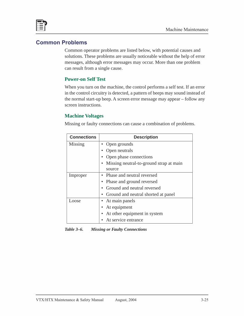
VTX/HTX Maintenance & Safety Manual August, 2004 3-25
Machine Maintenance
Common ProblemsCommon operator problems are listed below, with potential causes and solutions. These problems are usually noticeable without the help of error messages, although error messages may occur. More than one problem can result from a single cause.
Power-on Self Test
When you turn on the machine, the control performs a self test. If an error in the control circuitry is detected, a pattern of beeps may sound instead of the normal start-up beep. A screen error message may appear – follow any screen instructions.
Machine Voltages
Missing or faulty connections can cause a combination of problems.
Table 3–6. Missing or Faulty Connections
Connections Description
Missing • Open grounds• Open neutrals• Open phase connections• Missing neutral-to-ground strap at main
sourceImproper • Phase and neutral reversed
• Phase and ground reversed• Ground and neutral reversed• Ground and neutral shorted at panel
Loose • At main panels• At equipment• At other equipment in system• At service entrance

3-26 704-0211-211 VTX/HTX Maintenance & Safety Manual
Machine Maintenance
Fluctuating voltages to the machine often occur when power usage in your region is high (typically on a very hot or cold day).
Table 3–7. Problems Due to Power Fluctuation
If a machine malfunction occurs, consider the following issues:
• Is another machine that uses high current connected to the AC distribution power supply line?
• Is the ground impedance of the AC distribution power supply line sufficient?
• Are there fluctuations in the input voltage to the machine?
• Is there a source of “noise” nearby (crane, welder, etc.)?
• If other CNC or NC machines are connected to the same group of circuits, do any of those machines demonstrate similar problems?
• Was another machine operating at the same time the problem occurred?
• Does the problem occur mainly at a certain time of day?
Note
Power surges can occur when large loads are suddenly placed on, or removed from, an electrical system.
Problems Causes Solutions
Fuse blows. Power sag.
Repair faulty in-plant wiring.Move any other machines on the circuit to separate circuits.
Power is lost.Motor(s) overheat.Control PC boards and/or microprocessor fail.
Power spike.
Move any nearby high current switching devices (arc welders, inductive motors) away from the machine.
Machine stops. Properly ground equipment and install surge protection to insulate against lightning strikes.
Data is lost.

VTX/HTX Maintenance & Safety Manual August, 2004 3-27
Machine Maintenance
Coolant System
If a problem occurs with the coolant system, check these possibilities:
Table 3–8. Coolant System Problems
Machine operation failures can be a programming or a hardware problem. Hardware includes electronic components, wiring, and electro-mechanical devices.
Problem Cause Solution
Coolant flows slowly or stops.
Clogging due to dirty coolant.
Flush lines, clean filters, drain and refill the system with fresh coolant.
Pump is not working properly.
Check and service the pump. For mist system, check shop air pressure.
No liquid (only air) comes from mist nozzle.
Coolant tank is empty.
Fill coolant tank with fresh coolant.
There is too much air in the system.
Close off valve, then slowly open again to get desired flow.
Coolant fails to start when head lowers to Z up level or below.
Coolant valve is not turned On.
Turn on the valve (via the control).
Coolant is not programmed to be On.
Check the operating mode (auto or manual) or programming.
Coolant fails to stop when head is up to Z retract level.
Incorrect program parameters.
Check parameters and correct the setting.

3-28 704-0211-211 VTX/HTX Maintenance & Safety Manual
Machine Maintenance
Motion and Spindle Rotation
If the spindle or an axis does not move the way it was programmed to, moves without being instructed to, or spindle rotation is incorrect, refer to the following table.
Problem Cause Solution
Spindle does not turn.
Program might not have proper RPM setting.
Check the RPM setting in the program. If this setting is wrong, check and correct the entire program.
Spindle drive breaker is tripped.
Power down the machine, reset the breaker on the spindle amp and turn on power.
The machine’s control power is Off and the screen shows a Motion Error message
Chip buildup causes a Motion Error.
Look under chip covers for excessive chip buildup. Clean and maintain to avoid reoccurrence.
The X, Y and Z axes ballscrews are not well lubricated.
Check the lube oil level, lubrication to the way ballscrews, and lube pump operation. Correct as needed.
Servo cable connections are not making good contact.
Check each connector (by hand, visual check is not enough). Clean, press together and wiggle. Replace the connection if it is intermittent during wiggling.
Error LED is On servo(s).
Note the location of lighted LED(s). Phone for technical assistance.
Servo encoder or decoder not working properly.
Jog the machine while watching position numbers on the screen.
Actual collision or binding occurs between machine parts and product fixtures.
Examine the path, parts and fixtures for evidence of collision or rubbing.
(continued on next page)
Table 3–9. Motion and Spindle Rotation Problems

VTX/HTX Maintenance & Safety Manual August, 2004 3-29
Machine Maintenance
Problem Cause Solution
The machine chatters while machining or cutting.
Machine feeds too fast.
Check the program settings for Feed and Speed – reprogram if they are wrong.Make sure that the actual speed matches the programmed speed.
Wrong tool, tool is damaged, or tool is not sharp.
Make sure the right tool is being used for the application. Make sure the tool shaft is clean and not bent. Verify that the tool is sharp.
Fixture is not rigid enough.
Check the fixture. Tighten or reinforce it if needed.
Tool is not held perfectly straight.
Check the spindle taper for foreign material. Clean the taper if necessary.Check the tool holder to see that the tool is inserted straight. Reinsert the tool if needed.Check tool retention force on the draw bar.
Small errors in dimensions show up occasionally.
Temperature fluctuates as the part is machined.
Stabilize the temperature of the blank by providing enough coolant while machining.

3-30 704-0211-211 VTX/HTX Maintenance & Safety Manual
Machine Maintenance
Environmental Conditions
When the electrical cabinet overheats, the machine shuts down until the cabinet’s temperature sensor registers that the temperature has dropped to an acceptable level. If this error occurs, check the temperature around the electrical cabinet to be certain the cabinet is not subjected to an additional heat source, such as a space heater or bright sunlight from a nearby window.
Temperature and other environmental variables can cause problems that might otherwise be attributed to the machine.
Table 3–10. Environmental Factors
Problems Causes Solutions
Relatively small dimensional problems occur in the product.
Metal blanks stored in temperatures much higher or lower than the temperature of the machining area can expand or contract during and after machining.
Before machining, move the blanks to the machine area and allow the blanks time to reach ambient temperature.
Dust, debris, rust or discoloration accumulates on work surfaces.
Extreme temperatures are typical, and/or the environment is too humid or dusty.
Improve the machine’s environment. For example, close the machining area to outside dust, etc., and install air conditioning to lower room temperatures and humidity.
VTX/HTX Maintenance & Safety Manual August, 2004 3-31
Machine Maintenance
Ordering Replacement PartsImportant
If your local distributor is certified as a full service distributor, your call for replacement parts should be to that distributor.
Hurco maintains a large inventory of service parts. If your distributor is not a full service distributor, you may order parts from Hurco by telephone, fax, or mail:
Hurco Companies, Inc.One Technology WayP.O. Box 68180Indianapolis, IN 46268-0180Tel. (317) 293-5309 (products)
(317) 298-2635 (service)(800) 638-1849 (service parts)
Fax (317) 298-2621 (service)
Hurco subsidiary contact information can be found on the Hurco website:www.hurco.com
Providing Information Required for Parts OrdersIn order for your full service dealer or Hurco to process your order and supply you with the correct part(s), you must provide the detailed information described below.
• Your company’s purchase order number.
• Serial Number of the Hurco machining center. The machine serial number is located on the identification/data plate, which is attached to the electrical cabinet door.
• The part number, part name (description) and quantity desired. State where you found the part number. If you found the part number in a manual, include the manual’s part number, revision or date, and page. If you located the number on the part, write “old part.”
• Your company’s name and complete address.
3-32 704-0211-211 VTX/HTX Maintenance & Safety Manual
Machine Maintenance
• Name and telephone number of person ordering the parts.
• Complete shipping address for the parts, including name of the person to ship to, delivery date, department, etc.
• Provide any special shipping instructions, including mode of shipment. Parts will be shipped prepaid and billed via invoice.
• Indicate the condition of the machine (inoperable or functional, etc.).
• Address to which invoices are to be mailed.
Returning PartsWhen returning a part to Hurco, fill out a Return Authorization Tag and ship the part in its original container. All parts are subject to inspection before credit is issued. Non-warranty parts returned for credit are assessed a restocking charge. The purchaser is responsible for all shipping charges. Returned parts should be shipped prepaid. Hurco will not accept parts shipped COD or without a Return Authorization Number displayed clearly on the outside of the shipping container.
Important
After you contact either your full service dealer or Hurco, they will provide you with a Return Authorization Tag that includes the Return Authorization Number for you to display on the shipping container.
All defective parts replaced under warranty agreement must be returned within 30 days.

VTX/HTX Maintenance & Safety Manual August, 2004 704-0211-211
Record of Changes
Record of Changes
704-0211-211, 04/15/04, ECN 15691
Created by: Accent Technologies
Approved by: D. Skrzypczak 12/18/03
Page Subject Changes
New manual release, based on VMX Maintenance and Safety Manual, 704-0213-202

704-0211-211 August, 2004 VTX/HTX Maintenance & Safety Manual
Record of Changes
This Page Intentionally Left Blank.