Instability of multistage compressor K1501
13
N87-22203 INSTABILITY OF MULTISTAGE COMPRESSOR K1501 Zhou Ren-mu Hangzhou Steam Turbine Works Hangzhou ZheJlang, People's Republic of China The KlSOl compressor, driven by a steam turbine, is used to transport synthetic gas in fertilizer plants of lO00 tons daily production. The turbo- compressor set, which had been in operation since 1982, vibrated rather intensely, and its maximum load was only about 95 percent of the normal value. Damaging vibration to pads and gas-seallng labyrinths occurred three times from 1982 to 1983 and resulted in considerable economic loss. From the character- istics of the vibration, we suspected its cause to be rotor instability due to labyrlnth-seal excitation. But, for lack of experience, the problem was not addressed for two years. Finally, we determined that the instability was indeed produced by labyrlnth-seal excitation and corrected this problem by injecting gas into the mlddle-dlaphragm labyrinths. This paper primarily discusses the failure and the remedy described above. INTRODUCTION In recent years, China imported many large chemical plants that have var- ious kinds of compressors. Unacceptable vibration has occurred in some running compressors. The most serious occurrence was with the KTlSOI-KlSOl set that transported synthetic gas for a fertillzer-produclng process (at lO00 tons a day). Figure l shows the KTlSOl-1501 set, which consists of one steam turbine (including two cylinders) and three compressors. Its maximum power is 19 786 kW and its maximum continuous speed is II 230 rpm. It has a traditional concrete construction pad. Intensive vibration originated from the low-pressure compressor, KISOILP. Figure 2 shows the longitudinal section of its rotor. Table I shows the param- eters of the tilting pad of both bearings. Figure 3 shows the gas labyrinth construction of the middle diaphragm. Figure 4 provides a critical speed map and mode shapes for the rotor. Vibration occurred suddenly each time. May ?, 1982, when the speed was lO 800 rpm. observed: The first accident took place on The following characteristics were (1) The vibration of the shaft exceeded 80 _m suddenly. (2) The vibration accompanied intensive sound radiation (over 95 dB). (3) Sealing oil oozed out of the gas exit tube. (4) Intense floor vibration followed. When the cylinders were opened and examined, the following damages were observed: (1) The pads of radial bearing 074 were obviously deformed because of intensive journal vibration. 63 https://ntrs.nasa.gov/search.jsp?R=19870012770 2018-02-12T17:24:09+00:00Z
Transcript of Instability of multistage compressor K1501
N87-22203
INSTABILITY OF MULTISTAGE COMPRESSOR K1501
Zhou Ren-mu
Hangzhou Steam Turbine WorksHangzhou ZheJlang, People's Republic of China
The KlSOl compressor, driven by a steam turbine, is used to transport
synthetic gas in fertilizer plants of lO00 tons daily production. The turbo-
compressor set, which had been in operation since 1982, vibrated rather
intensely, and its maximum load was only about 95 percent of the normal value.
Damaging vibration to pads and gas-seallng labyrinths occurred three times from1982 to 1983 and resulted in considerable economic loss. From the character-
istics of the vibration, we suspected its cause to be rotor instability due to
labyrlnth-seal excitation. But, for lack of experience, the problem was not
addressed for two years. Finally, we determined that the instability was
indeed produced by labyrlnth-seal excitation and corrected this problem by
injecting gas into the mlddle-dlaphragm labyrinths.
This paper primarily discusses the failure and the remedy described above.
INTRODUCTION
In recent years, China imported many large chemical plants that have var-
ious kinds of compressors. Unacceptable vibration has occurred in some runningcompressors. The most serious occurrence was with the KTlSOI-KlSOl set that
transported synthetic gas for a fertillzer-produclng process (at lO00 tons a
day). Figure l shows the KTlSOl-1501 set, which consists of one steam turbine
(including two cylinders) and three compressors. Its maximum power is
19 786 kW and its maximum continuous speed is II 230 rpm. It has a traditional
concrete construction pad.
Intensive vibration originated from the low-pressure compressor, KISOILP.
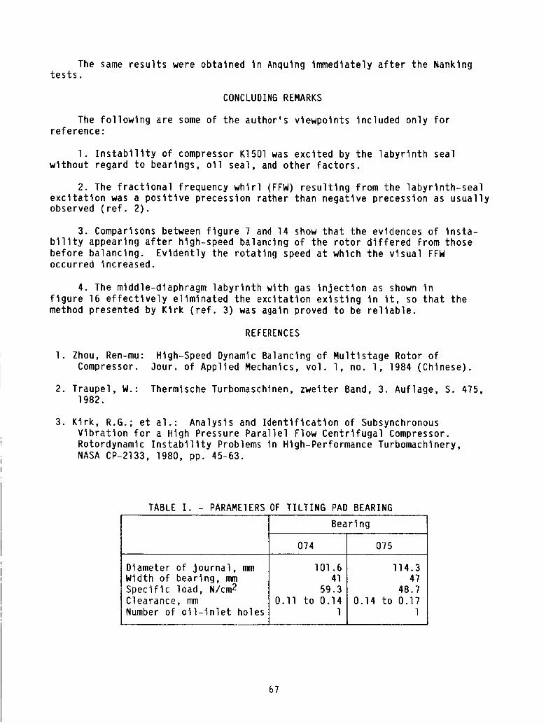
Figure 2 shows the longitudinal section of its rotor. Table I shows the param-
eters of the tilting pad of both bearings. Figure 3 shows the gas labyrinthconstruction of the middle diaphragm. Figure 4 provides a critical speed map
and mode shapes for the rotor.
Vibration occurred suddenly each time.
May ?, 1982, when the speed was lO 800 rpm.observed:
The first accident took place on
The following characteristics were
(1) The vibration of the shaft exceeded 80 _m suddenly.
(2) The vibration accompanied intensive sound radiation (over 95 dB).
(3) Sealing oil oozed out of the gas exit tube.
(4) Intense floor vibration followed.
When the cylinders were opened and examined, the following damages wereobserved:
(1) The pads of radial bearing 074 were obviously deformed because ofintensive journal vibration.
63
https://ntrs.nasa.gov/search.jsp?R=19870012770 2018-02-12T17:24:09+00:00Z

(2) The gas labyrinth of the middle diaphragm and the ends of the cylinderwere worn out. Somewear scars remained on the surface of the shaft.
Whenonly the damagedparts were replaced, the vibration and damagereoc-curred when the speed reached lO 820 rpm.
There are three identical sets of this kind in our nation - in Nanking,Anqlng, and Guangzhou. This type of failure occurred in all three compressors.The most serious failure was in Nanking. Becausethe failures were clearly notaccidental, the Chemical Engineering Ministry began and directly guided exper-imental research in Nanking. (All the phenomenadescribed above occurred inNanking.) The following is a description of the whole test, which was dividedinto three steps.
FIRSTOFSTEPOFTEST(May 1982 - January 1983)
At first we did what we could to minimize downtime and production losses.The origin of the vibration was rotor instability as will be detailed. Althoughthe labyrlnth-seal excitation was considered to be the cause of the instabil-ity, the posslbillty of oll whip had not been dismissed at that time. There-fore the following measureswere adopted:
(I) Six teeth in the middle of the diaphragm labyrinth were removed.
(2) The ratio of bearing width to diameter was decreased from 0.40 to0.39 mm.
(3) Additional displacement transducers were installed on bearings 074 and
075 (fig. l) to improve vibration monitoring.
Because none of these measures eliminated the rotor instability, a large
quantity of measurements and analyses were then made. This work was performed
mainly by ZheJlang University. Because vibration was monitored closely during
the experiments, no serious damage occurred.
Figure 5 shows frequency spectra of the shaft vibration in direction x
on bearings 074 and 075 at a speed of lO 220 rpm as measured by a transducer
on November 19, 1982. From flgure 5, the rotating speed was 170.3 Hz, and the
frequency of fractional frequency whirl (FFW) was 80 Hz. The frequency ratio
nF equalled 0.47. The vibration amplitudes of the components in this figureare almost equal. Figure 6 shows a frequency spectra of the shaft vibration
in direction y on bearing 074 and in direction x on bearing 075 at 9460 rpm
on November 19, 1982. Again, the vibration amplitudes were almost equal. The
frequency of FFW was 77 Hz (measured), the rotating frequency was 157.? Hz, and
the frequency ratio nF equalled 0.488. So obviously the FFW appeared at9460 rpm.
Figure 7, which gives a speed-spectrum map from an experimental recording,
indicates that the FFW appeared Just at 8000 rpm and that nF equalled 0.5.Amplitude increased rapidly with increasing speed, but frequency dropped
sllghtly_
Figure B shows an evolution of the shaft center orbit measured on bearing
0?4 at 9200 to 9480 rpm on December 18, 1982. It was photographed from the
cathode oscilloscope.
64

All of the test results fully demonstrated that the vibration came fromthe instability of the rotor, but the nature of the instability was not
determined. So a power spectrum referring to the vibration of bearing 074 and
to the pulse pressure of the gas outlet was made. The transfer function and
the coherent function were also calculated. However, the nature of the
instability was still not evident.
The following additional changes were performed in this step:
(1) The inlet temperature of the lubricant oll was changed from 40 to45 °C.
(2) The opening level of the compressor-protectlng valve was changed from
40 to lO0 percent.
(3) The inlet gas temperatures and pressures of the compressor were
changed.
Yet no consistent, useful results were obtained.
At the same time, some temporary measures were taken during the tests:
(1) A middle vertical slipping pin was added on the body of the compressor
to prevent motion caused by expansion of the cylinder.
(2) The supports were packed with insulation to prevent the cold currentheat losses from influencing them.
Attention was also paid to the pads and oil-seallng sllprlng of the cyl-
inder, but no effects were obtained.
SECOND STEP OF TEST (February - October 1983)
To clarify the nature of the instability, we decided to observe the
dynamic properties of the rotor KI5OILP on a balancing machine. This test was
performed by Hangzhou Steam Turbine Works (ref. l). The test included the
following:
(1) High-speed balancing of the rotor(2) Observation of the critical speed and its insensitivity to other
parameters
(3) Increasing the number of the oil-lnlet holes in the
bearings
(4) Increasing the clearance in the bearings
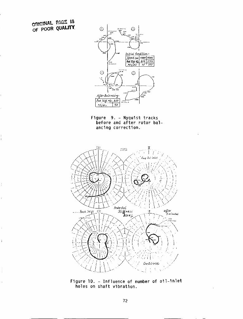
Figure 9 shows the Nyqulst tracks before and after the balancing cor-
rection. Before the correction the severity of the bearing vibration increased
quickly when the speed exceeded 9000 rpm. For the sake of safety the pedestal
stiffness was increased from 820 to 2250 N/_m. When the speed reached
II 230 rpm, the two bearings were vibrating at 6.5 and 2.2 mm/sec, respec-
tively. This result indicated poor balancing. We found that the mixed vibra-
tion of the second and third modes appeared before the second critical speed
was reached. Using the method of modal separation, we corrected the unbalanceof the rotor. The bearings were vibrating at only 0.3 and 0.35 mm/sec, res-
pectively, when the pedestal stiffness was restored to 820 N/_m. The first
65

critical speed was 4000 rpm and the second was lO 700 rpm; these speeds are in
agreement with the results of our calculation. The results of our experiment
on insensitivity indicate that the rotor Is sensitive to unbalance at
II 230 rpm. (This does not conform to American Petroleum Institute (API)
standards.)
The Nyqulst tracks of the rotor with one and with five oil-lnlet holes(one hole for each pad) in the bearing are shown in figure lO. The dotted
lines in the figure show a change of rotor vibration for one oil-inlet hole.
However, oll whip did not take place. The oil clearance was increased from
0.15 to 0.20 mm, but the state of the shaft vibration did not change. It was
impossible to test the labyrlnth-seal excitation, for the rotor was driven ina vacuum chamber.
In brief, hlgh-speed balancing showed clearly that the instability of the
rotor did not come from the oll whip.
THIRD STEP OF TEST (November 1983)
To eliminate the vibration failure rapidly, we cooperated with Mltsublshl
in completing a series of tests on November 5-8, 1983. The test speeds were
to lO 222 rpm on the first day, and to lO 550 rpm on the third day. All the
tests were within specifications. The test procedure for the fourth day is
shown in figure II. After reaching lO 750 rpm and running for an hour, the
shaft vibrated intensely.
Figure 12 shows a real-tlme analysis of the shaft vibration during stable
operation. Figure 13 shows the same analysis during a period of instability.
Figure 14 gives a three-dimenslonal spectrum analysis of the shaft vibration
in direction x on bearing 075. Figure 15 shows an orbit of the shaft center
during instability.
The tests just described make clear the inevitability of rotor instabil-
ity. But comparisons between figures 7 and 14 show that the latter tests didnot produce considerable FFW before instability appeared, and the amount was
less than that of the operational speed-frequency map by 25 dB (fig. 12). Just
before the rotor became unstable (fig. 14), the frequency of the FFW was
74 Hz/sec (which is the same as in fig. 12). This frequency suddenly rose to
80 Hz after 5 sec (which is in agreement with fig. 13). The frequency ratio
nF equalled 0.4465.
MEASURES TAKEN
Although much important data on the dynamic properties of the rotor were
acquired through the three steps of the tests, the nature of this instabilityhas not been directly determined. According to the information and inference,
however, the origin of the instability is labyrlnth-seal excitation. The com-
pressor manufacturer also provided some suggestions for improvements.
Finally, a decision was made that gas should be injected into the laby-rinths of the middle diaphragm. The new construction is shown in figure 16.
After this measure was taken, the instability was eliminated. Figure l? shows
a frequency spectrum of the shaft vibration on bearing 074 at lO 690 rpm before
corrective measures were taken, and figure 18 shows this spectrum after cor-rective measures were taken. It can be seen that the FFW was eliminated.
66
The sameresults were obtained In Anqulng immediately after the Nankingtests.
CONCLUDINGREMARKS
The following are someof the author's viewpoints included only forreference:
I. Instability of compressor Kl501 was excited by the labyrinth sealwithout regard to bearings, oll seal, and other factors.
2. The fractional frequency whirl (FFW)resulting from the labyrlnth-sealexcitation was a positive precession rather than negative precession as usuallyobserved (ref. 2).
3. Comparisonsbetween figure ? and 14 show that the evidences of insta-bility appearing after hlgh-speed balancing of the rotor differed from thosebefore balancing. Evidently the rotating speed at which the visual FFWoccurred increased.
4. The mlddle-dlaphragm labyrinth with gas injection as showninfigure 16 effectively eliminated the excitation existing in It, so that themethod presented by Klrk (ref. 3) was again proved to be reliable.
REFERENCES
I. Zhou, Ren-mu: Hlgh-Speed DynamicBalancing of Multistage Rotor ofCompressor. 3our. of Applied Mechanics, vol. l, no. l, 1984 (Chinese).
2. Traupel, W.: Thermlsche Turbomaschlnen, zwelter Band, 3. Auflage, S. 475,1982.
3. Kirk, R.G.; et al.: Analysis and Identification of SubsynchronousVibration for a High Pressure Parallel Flow Centrifugal Compressor.
Rotordynamlc Instability Problems in High-Performance Turbomachlnery,
NASA CP-2133, 1980, pp. 45-63.
TABLE I. - PARAMEIERS OF TILTING PAD BEARING
Diameter of journal, mmWidth of bearing, mmSpecific load, N/cm 2
Clearance, mmNumber of oll-lnlet holes
Bearing
074
I01.6
41
59.3
0.II to 0.14
1
075
114.3
47
48.7
0.14 to 0.17
1
67

KI5OILP KTI501 _I501MP KI5OIHP
!074-bmae_n_1-075 028a 028b 028c 108 ll5 126 133
Figure I. - Steam turbine compressor set of KT150-KI501.
Figure 2. - Rotor of KI5OILP.
,_\ "\\
it " \'\'7/'//,'/////I"L\ 'I
_/;I/' /KI:''/_ t
//ll:///l' "' 't ,'l//,.//
_ g
Figure 3. - Labyrinth construction.
68

ORIGINAL PI_G_ iS
OF POOR QUALITY
_0 20
_/0
•,..t 7"4._
4._05
q
3
I_i_ti!!!!:
Ill',lm
i _ ::l:::i I li it! ililm_li_IY'ii_"
!ii:H,_-H-+--_+-i _._L-.-.ii_h/:,,illI L I_! . ' ::
!L_-H3i't IlL:
_tL::7"iFr'_ i-i//i h'iq_-,_27.g!.
_I_tD71111i lilitftl]_t<_lh11": ii! i_71iifli I i illtlltltili_:iIltlI' I " t',_J'7,17......I.tlt.tltli_7,1+:-]!7
support sti£_nes._ 10 _ N/IG
' J _- _ 2 _ J IO #l IZ #J/14 ll" 17 21
I-]-i,;oLLI/I !17 oou_]._,_
I I i/I/<-, support
I_.I-I-/_' ""_'_',"_t__I -1 820 N/_i
Figure 4. - Critical speed and mode shapeof rotor KI501LP.
69

ORIGINAL PAGE IS
OF POOR QUAUTY
"°!! ++i_';t_!;-!=!;i__i:l HI+
_L___
+ +,- - . + LI I -,':I . +. ++......+,_-.. ++++I+_+,-,,'+I+-: ++-:,i,l+:,_++:,,o,.++,-,,++,pZ/+,t/9.._ :._ l)+' ;,+-:- ---_- ..,_ l+ll :.-._..+-,.,_+_,+ +I- I
• _+ - - p" • .... -I ...... q '- --+- ' : ___ • ..... _ ..... + " I - i I "
:_._.., r + + ..... I .... I+ ' __+. I., I ...... II--:--I--+-----..... _ I ' __ 1'1 _ _W ----_=I_ll--'--I +r+l:_'':+'+_ I + 1
.......... +]++.......... :.- --:::;-: +:: I = - I--': I_ I
-_+_...... +° ,L+ , _,zt,+:+.
lJJ;
ii.
Figure 5. - Frequency spectrum of shaftvibration in bearings 074x and 075x at10 220 rpm (Nov. 19, 1982).
.,,++iI,+....I!+-I-
+ ..... i-. i.._, it, w. :, ....
!i_o
Figure 6. - Frequency spectrum of shaft
vibration In bearings 074y and 075y at
9460 rpm (Nov. 19, 1982).
7O

ORIGINAL _"_
OF POOR QUALITY
FFW I _r, z _ R P_
_ ,.----_..,_ : ,
,___._--__ _--J,PN I
0 fo top I_-o /oo ?.5o 30o ,_(P _oo ._Jo-_o0
Figure 7. - Vlbr_,tlon zjeed-spec-
trum map.
Orbit shi_t of 074 journal
centre (9200-9480 rpm
82.12.18 __
F" ht_
!"i
F _
\
) [,_-_._
i
I
i
\ ¢
\ . /
Figure 8. - Orbit of shaft center on bearing0?4 from 9200 to 9600 rpm.
71
OF pOOR QUALITY. Q
Io.
_j,
o)
II ,)..I,) G
U,--- ,)
G .... ©
A_ler SaZ_ oc_'_J , .'7
"/_/d,', f O J
Figure 9. - Nyqulst tracksbefore and after rotor bal-
ancing correction.
J - t " / , \ # -_t " , }" / , -" P,vc O,b,'.A.t . ,'" "',
-.../\.i ,,'--. "..,,i >- " -,-I/ZT:,. -, .+-,,. /.-, '.,I.t -,-x ,
;.,+:>1<-.!>!--\--\_, :.', / -<<
-__./..,.-., 7_1.---,,,, ;, .,, I t \\ ,., ... ,,.-.,c" > "] "" " "'_ / ' \ )_'>\ \\<'"i ./
__x..i Pedefta_ -.. ) _t....
..... _,,_<._tc _c_p _t4_,ess ,Ti ,_(t_,-)_ - I / 7-_.. d, /i l_ ¢'\ _ i i _"_
,"_ .......t l I / ix /k \ ' , . , )" .....
/',,',C.-_m- I-/?-7L.>-,,,/'.,,.",--': (_ ,,-:-.?_"-',-_'",.S'\', i-- -.. .-..i ", ,:'"',' .\ ..... _......... •
--_ i ./\_ .......,___.... , \...I./'-,,.-. >.'.I;-__" . •
I ' : ..-':. .... II i .... :, , 1
.._.:-,\--']i./,/71i',",c%,'_<'-.,-,.:-","..,',' ." ,'"'. ./ \./ ll. /.1_ i _, \_k'_ ' t I \ \/ / ,',,1_'\', ' " '
\.-"::-"_:_ ll'_"J,..'• ,...i,>_...,,,.,. .. .. i", ./.."7'-_:'"" :,..t ., ".-_ I i ' • I
':...,-'.<' ," i \_ ". ,./"C , ,,' o,,ol-,,_,_ .""" " :-._.,'; '. ..:"
Figure I0. - Influence of number of oil-lnlet
holes on shaft vibration.
72

%_a
,-,,...-.,'-'IS%
OF POOR QUALITY
I0 76"0 rpm
fob_o "t" [
[__e.lll--"
O;L-lempereLZ_re "_l_q3 "C
,_ Measureme_F
[
/O 7O0 rt,_,
II
I--- 2 hntzrS
, i L ,
Figure 11. - Test procedure for November 8, 1983.
.+
_6_ 1 I/ FFW
LIH !OOHz
"r,'r ¢'; Cn:T
07=,y i loT_-Orp,_
C'l; i glrI_i PIP,) rJ;t
.; -7-I -I
Lrl I UILI
Lt I FFP/
l_t' I I'" rRi,
llr IH"Fgt
' 1r.._i _ O0 F.L_
X= 74.8 FLz Vt _3a.2dE_J _: 74.3 H_ yl -39.2deU
I _,r. g; BA _
-2 -?-} -1
4
L1i UI
FFW L, L,/ 1_'_, YFW "rpl,
I "e _
I +_ + _ I ' _ [;_ ; 1 , l [ "all;
• LIH " " 7EC'JHZ LIH ' 2_3P=
Xl 74.8 HZ V= -37.34B _J ×z 74._ H: V! -43._J_U
Figure 12. - Real-time analysls of shaft vibrationat I0 750 rpm before rotor instability.
73

ORIGINAL _:'_ ]S
OF. POOR QUALITY
¢@JO(PE'_) FH_'( _mJB
(
07#x_
dB
- 1 I,!,i
FFW/
E_< _ /2 _ e '" ' .... "'" _=' _ /7. ,_ g_
o 7#-y
LIN
XI B'_.G Hz V:;-17.9d@U
!
stlqP_J
_o_r-2
g_-Z1 -ui Ikt I
TRIG t
.l_I r
o7_-x{
dB
fo 7FO 9_..-.
yFW
t'1 , I ....
L]II
X! ,BO.O H: Yl -19,4dl_J
kill _-"0c2HZ
)_: _O.O H= W -14.1JE'J
_,_:'FFI'.) rl_ ,li') L'_IT_.NIC_H V:UF) (r6q.-_;
0 74->,
__or
F.O_t /
FF W
t _ ,-_-Drp-
iL
! /Vt -2._- |I_PU
_Lc:!
-1
3
rq[_
F! _.
F.I_l
ii 1_.
Figure 13. - Real-tlme analysis of shaft vibration
at lO ?50 rpm during rotor instability.
Figure 14. - Three-dlmenslonal spectrum of shaft vibra-
tion in bearing 075 at lO 750 rpm during instability.
0 74 /_
Figure 15. - Orbit ofshaft center on bear-
ing 074 at lO 750 rpm
during instability.
74

ORIGW_.L '""'_'" ""
OF. POOR QUALrfY
dHo/¢5 @6
/':
i /
7ord 2I teet_ 7_ Hoie_ ck4_6
Figure 16. - Construction of
new labyrinth.
, ..... h .... / .... ] ,obTot,
I : ; I _ "' /t ;-_ /t-T."!l- _-_ ...."'j "' ; " F -I :-- FFW :1 I --; "-./-T'_---_ -FT-Z-T-TI_--:"
' ' ' / .... 1 _ " " ' .... J
.!o/ : iLr_ ; I : 'f : I _ _-T-lz-:-i -
Figure 17. - Frequency spectrum of shaft vibra-tion on bearing 074y taken with old labyrinth.
'--5
F .it
"-;to
"-.-t3
o-_to
,. (
re f_ }I . _B w ,. =
_.e. fe " • .: - - I - i .._°____f__l_.
- i -I II0 70 H= 50 100 tOO Hz. _00 KX:)0 ZOO0
Figure 18. - Frequency spectrum of shaft vibra-
tion on bearing 074y taken wlth new labyrinth.
75