3my.chemeng.queensu.ca/courses/integratedDesign/Resources/... · Web viewThe complexity of using...
21
Mody and Marchildon: Chemical Engineering Process Design Chapter 13 TRANSFER OF GASES; COMPRESSION AND VACUUM P:/CEPDtxt/CEPDtxtCh13 13.1. Transport of Gases: In applications of low pressure (Inches of Water), thin walled (sheet metal) ducts and fans are used. In the range of up to 2 to 3 inches water differential pressure, an Axial Fan can be used. In the range up to typically about 20 or 30 inches water, a centrifugal fan can be used (though there are examples of these fans producing 100 inches of water differential). Axial Fan Centrifugal Fan Northern Blower www.northernblower.com Refer to such vendors as Chicago Blower (www.chiblo.com ), Northern Blower (www.northernblower.com ), and Howden Buffalo (www.howdenbuffalo.com ) for further information.
Transcript of 3my.chemeng.queensu.ca/courses/integratedDesign/Resources/... · Web viewThe complexity of using...

Mody and Marchildon: Chemical Engineering Process DesignChapter 13 TRANSFER OF GASES; COMPRESSION AND VACUUM
P:/CEPDtxt/CEPDtxtCh13
13.1. Transport of Gases:In applications of low pressure (Inches of Water), thin walled (sheet metal) ducts and fans are used.
In the range of up to 2 to 3 inches water differential pressure, an Axial Fan can be used. In the range up to typically about 20 or 30 inches water, a centrifugal fan can be used (though there are examples of these fans producing 100 inches of water differential).
Axial Fan Centrifugal Fan
Northern Blower www.northernblower.com
Refer to such vendors as Chicago Blower (www.chiblo.com), Northern Blower (www.northernblower.com ), and Howden Buffalo (www.howdenbuffalo.com) for further information.
The defining line between a high pressure fan and a blower is not really stated, but at differential pressures above several psi, usually a blower or a compressor is used. When a centrifugal device is desired, the small blowers such as regenerative type blowers are used (to about 10 psig). Multistage centrifugal blowers are available typified by ‘hoffman’ blowers (www.gardnerdenver.com) which can produce differential pressures in the order of 25 psi.

“Hoffman Blower”www.gardnerdenver.com
Positive displacement blowers, usually rotary lobe types, are common in these applications.
Rotary Lobe BlowerAerzen Blowers and Compressors (www.aerzen.ca)
Other vendors of the rotary lobe blower are Roots Blower (www.rootsblower.com) and several others.
Beyond this pressure range, people usually refer to the device as being a compressor of which there are several different designs, but they generally fall into the two categories of “dynamic” (typified by centrifugal and axial) and “positive displacement” (typified by

rotary screw compressors and reciprocating compressors). The centrifugal compressor operates very much like a centrifugal pump, with a high speed spinning impeller. Pressures to about 300 psi are not uncommon with centrifugal compressors (refer to the section below on process compressors). A few vendors of centrifugal devices are:Atlas Copco www.atlascopco.co Dresser Rand www.dresser-rand.comIngersol Rand www.irco.com Gardner Denver www.gardnerdenver.com
The screw compressor, is the commonly used device for pressure differentials up to about 150 psi.
Aerzen Canadawww.aerzen.ca
Reciprocating compressors can be obtained with about any differential pressure required.

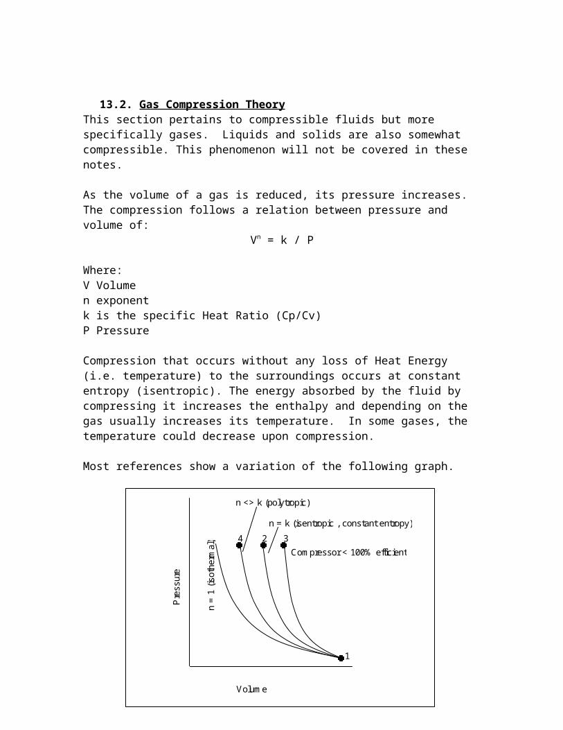
13.2. Gas Compression TheoryThis section pertains to compressible fluids but more specifically gases. Liquids and solids are also somewhat compressible. This phenomenon will not be covered in these notes.
As the volume of a gas is reduced, its pressure increases. The compression follows a relation between pressure and volume of:
Vn = k / P
Where:V Volumen exponentk is the specific Heat Ratio (Cp/Cv)P Pressure
Compression that occurs without any loss of Heat Energy (i.e. temperature) to the surroundings occurs at constant entropy (isentropic). The energy absorbed by the fluid by compressing it increases the enthalpy and depending on the gas usually increases its temperature. In some gases, the temperature could decrease upon compression.
Most references show a variation of the following graph.
In an ideal situation, the compression occurs along a single curve with the exponent n and constant k (ratio of the specific heats of the gas, cp/cv). When n = 1, the compression has been done isothermally (constant temperature). When n = k, the compression has been done at constant entropy (isentropic).
Volume
Pre
ssur
e
n =
1 (is
othe
rmal
)
n = k (isentropic , constant entropy)
n <> k (polytropic)
Compressor < 100% efficient
1
2 34
Using a mechanically perfect compressor, the work injected by the compressor to get the gas from one pressure to the other pressure is exactly the gain in enthalpy the gas experiences. However, since compressors are not ideal, they add to the enthalpy of the gas beyond what is required. The net effect is to increase the gas temperature, often substantially.
Calculating Exit Temperatures and Work
Here’s a simple example you can reproduce with a set of steam tables or better yet the graphical representation of the steam tables, a Mollier Chart for steam. The method used here (using pressure-enthalpy data) is the preferred method of doing compressor calculations. The method makes no assumptions about the physical properties in that it does not assume an ideal gas is being compressed.
We start with steam at 30 psia and 320 °F. The physical properties at those conditions (Point 1) are:Enthalpy (H) = 1198.9, Entropy (S) = 1.746, and the Volume (V) = 15.23 ft3/lb
1
2
3
4
Isothermal

The compression to 50 psia following a line of constant entropy takes us to a new set of conditions (Point 2) of:Temp (T) = 419.9 °F, Enthalpy (H) = 1244.8 BTU/lb, and the Volume (V) = 10.3 ft3/lb
The Change in enthalpy from (1) to (2) amounts to H = 45.9 BTU/lb. Point (2) would be the point we would reach if we had a mechanically perfect compressor. To calculate the work, or horsepower to reach this point, we need to know the gas flow. If the mass flow is 1000 lb/hr, then the horsepower is 45.9 * 1000 = 45,900 BTU/hr = 18 hp.
If we assume that a real compressor has an adiabatic efficiency of 50%, we can calculate the actual horsepower of a real compressor. The definition of adiabatic efficiency is the ideal enthalpy change to achieve the new conditions divided by the actual enthalpy change the gas has undergone.
eff = Enthalpyideal / Enthaplyactual
Therefore the Actual Enthalpy change would be 45.9 BTU/lb / 50% = 91.8 BTU/lb, and the horsepower requirement would be 36hp (assuming 1000 lb/hr is being compressed).
We find the exit point of a real compressor with a 50% efficiency (point 3) on the curve by following the constant pressure curve up to the enthalpy point of 1198.9 + 91.8 = 1290.7 BTU/lb where we find the properties of the steam are:Temp (T) = 513.5 °F, Entropy (S) = 1.796 the Volume (V) = 11.47 ft3/lb
It may be that this temperature and pressure is adequate for the process requirements. However, if it’s too hot and so we choose to cool the gas, (either by cooling the gas after it has been compressed or during the compression) we will follow a line of constant pressure to a new temperature value. Let’s assume we cool the gas down to 350 °F at constant pressure. The new properties at point 4 are:
Temp (T) = 350 °F, Enthalpy (H) = 1209.9 BTU/lb, Entropy (S) = 1.7 BTU/lb and the Volume (V) = 9.4 ft3/lb
Since the volume of the gas is now somewhere between the Isothermal Volume and the Isentropic Volume, we have effectively traveled from Point 1 to Point 4 via what’s known as polytropic compression. If the gas compressor had cooling during the compression, you could reach point 4 in one physical step.
Note that if we had cooled the gas during the compression the final enthalpy would be 1209.9 BTU/lb and therefore the horsepower requirements of the compressor would be 11,000 BTU/hr (4.3 Hp).
Where this becomes of practical importance, beyond that of merely calculating the horsepower and exit temperatures is when it’s chosen to split the compression up into stages and cool the gas between stages. By cooling the gas on the inlet to a stage, we reduce the horsepower requirement of that stage. The net effect of cooling the gas

between stages is to reduce the overall horsepower requirements, as compared to a single stage unit.
Most real compressors operate with a value of n somewhere between 1 and the value for k. The operating curve is called “polytropic” compression. The closer n is to a value of 1 (isothermal operation), the more efficient the device is from a horsepower requirement. Reciprocating compressors that utilize cooling of the cylinder walls can approach isothermal operation and any compressor that breaks the compression up into stages and uses a cooler between the stages reduces the value of n.
The number of stages to use:For most available compressors, compression ratios (Pdisch / Pinlet) usually vary from 1.05 to 7 per stage, however, a ratio of 3.5 to 4 per stage is reasonable for most process operations. Also, the sealing systems are usually limited to about 300 °F (148 °C). Some gases such as oxygen, chlorine and acetylene require that the temperatures be maintained below 200 °F (93 °C). The number of compression and cooling stages can be estimated based upon meeting this requirement.
Calculating Compressor HeadYou’ll see reference to compressor ‘head’ below. The required head can be calculated from the differential isentropic enthalpy as follows:
Headisentropic (ft)= enthalpyisentropic (BTU/lb) * (778 ft lb/BTU)
or, in consistent units
Headisentropic = enthalpyisentropic / g
Total Compressor HorsepowerThe horsepower calculated above was the “Gas Horsepower,” (GHP), however, to obtain the total horsepower requirements, the losses due to friction in bearings, seals and speed increasing gears must be added. An approximate equation for this is:
Brake Horsepower BHP = GHP + Mechanical LossesWhere: Mechanical Losses = GHP0.4

When Pressure – Enthalpy data is not availableAs mentioned above, the most accurate method for determining the horsepower requirement is to use Pressure-Enthalpy information. Using a process simulator or equations of state makes this a reasonable approach. However, when Pressure-Enthaply information is not available, the horsepower can be calculated based on the ideal gas equations. The required ‘head’ can be calculated and given the mass flow of gas passing through the compressor, the horsepower can be obtained.
The formula for an adiabatic compression is:
Where:Zavg is the average gas compressibility, a correction for non-ideal gases = (Z1 + Z2) /2His = Isentropic HeadGas_R = Gas ConstantT 1= Inlet Temperature (abs)P2 = Gas Discharge pressure (abs)P1 = Gas Inlet Pressure (abs)k = cp/cvMW = Molecular Weight
w = mass flow rateis is the Isentropic efficiency
The approximate theoretical exit temperature, at 100% efficiency is:
HisZavg Gas_R T1
MWk 1( )
k
P2P1
k 1
k
1
Ghpw His
is

where p’s are pressures absolute, and T’s are temperatures absolute.
If the compressor follows a polytropic path instead of an isentropic path, the polytropic head and horsepower can be calculated by substituting k with n and using the polytropic efficiency instead of the isentropic efficiency.
Polytropic and Isentropic head are related by:
Field Determination of Compression HorsepowerThe complexity of using these calculations to determine energy use or motor horsepower for a multistage compressor, in combination with having to know the adiabatic and mechanical efficiencies (which may not be available) has led to a simplified empirical approach. Using a current meter to determine the electrical power usage of the compressor and an air flow meter to determine the gas flow through the compressor, a value for the air flow SCFM (cu ft /min)/kW of electricity can be determined.

13.3. Selecting the Right CompressorLarge Scale Process Compressors tend to fall into two groups either Positive Displacement or Dynamic. A large proportion of the process compressors that are used are either reciprocating or centrifugal (usually multistage).
Compressor Coverage Chart (used with permission from GPSA, web: gpsa.gasprocessors.com)

A Comparison of Gas CompressorsType of Compressor
Oil Lubricated
ScrewOil Free Screw
Centrifugal
Oil Lubricated Reciprocati
ng
Oil Free Reciprocati
ngTypical Capacities, ACFM
150 – 10,000
250-50,000 200-100,000+
0-6000 0-6000
Maximum Inlet Pressure P1, psig
Generally 100, but can go to 700
Generally150, but can go to 225
Close to P2
Close to P2 Close to P2
Maximum Discharge Pressure P2, psig
865 400 1500 – 5000
6000
Maximum Discharge Temp T2, °F
250* 400 – 500 350 – 500 300 – 400 < 300
Maximum Compression Ratio per stage
23:1 5:1 1.5 – 3:1 5:1
Adiabatic Efficiency at design pt.
70 – 85%,50% at
15:1 compression ratio
70 – 85% 70 – 88% 80 – 92% 75 – ? %
Reliability/availability, %
98 – 99.5 99 – 99.5 98 – 99.5 92 – 95 92 – 95
* most lubricants break down at 280 °F
Centrifugal Compressors are Constant Head DevicesOne thing to note is that Centrifugal compressors are constant head devices (like centrifugal pumps). This means that when curves for a centrifugal device are shown in psi or kPa, they are for a particular gas molecular weight (usually air). When the same compressor is operating with a different gas, the compressor will not produce the same differential pressure. For this reason, low molecular weight gases (less than 10) are not practically handled by centrifugal devices because to achieve a reasonable pressure, the required head is too large for any industrially available centrfigual compressor; a reciprocating compressor is normally used instead.
Reciprocating CompressorsReciprocating compressors use a piston and cylinder to draw gas into the compressor and compress it into the discharge system. They can be multistaged easily and oil lubricated units can have adiabatic efficiencies in the 80 to 92% range. Non oil lubricated units have lower adiabatic efficiencies. If the compressor is oversized or the process is

operated at off-design points, the high efficiencies are generally lost. Non oil lubricated compressors typically have lower allowable gas exit temperatures.
Positive displacement reciprocating compressors are the most economical device where:-Discharge pressures are greater than 865 psig and flow is less than 2000 ACFM.-Discharge pressures above 500 psig when the flow is less than 300 ACFM-Any discharge pressure when the flow is less than 200 ACFM
Reciprocating compressors suffer from reliability / availability issues in comparison to centrifugal machines (see chart above).
A special type of reciprocating compressor (the diaphragm compressor) uses a moving metal diaphragm to compress the gas. These compressors provide the highest pressures of any compressor (about 15,000 psig), but are limited to no more than 100 ACFM.
Centrifugal CompressorsCentrifugal compressors are extremely popular because most are close to being oil-free. Although oil is used in the compressor which can create an aerosol, the special sealing systems used in most centrifugals reduce the level of oil contaminants to very low levels. Centrifugals are also popular because of the very large capacities (> 100,000 ACFM) that are possible with a single compressor, combined with fairly high pressures (1,500 to 5000 psig). Centrifugals are economically attractive when flows are high, and they are the only choice in many high flow / pressure situations.
If other compressors are available which will meet the same pressure/flow requirements, centrifugals are preferred when the process requirement allows for a fixed pressure ratio and requires oil-free gas. Normally, given the situation where centrifugal and reciprocating compressors have similar costs, the centrifugal is selected for its uptime advantages and lower lifecycle costs. Centrifugal units can be built to run without any installed spares (99+ reliability) if API (American petroleum Institute) 617 standards are followed, where reciprocating units usually require an installed spare.
Keep in mind, centrifugal units often have higher installed costs than recips and screw compressors for the same pressure/flow range, and they are inflexible to changes in pressure ratios (i.e. their capacities drop significantly as the discharge pressure rises).
Screw Compressors (Oil Lubricated and Oil Free)Screw compressors operate using two helical rotors. The rotors mesh together creating a cavity that draws gas from the inlet and delivers it to the discharge. The rotors have very tight clearances and are prevented from touching each other using timing gears. Oil Lubricated compressors inject oil for lubrication, sealing of the rotors and to draw away heat of compression (thus improving the isentropic n value). Although the oil is in contact with the process gas and the two contaminate each other, recent advances in filtration can ensure oil free gas to about 1 part per billion. Screw compressors are reported to be good in low molecular weight applications (i.e. hydrogen).

Aerzen Screw Compressor (www.aerzen.ca)
13.4. Gases with solidsScrew Compressors have the advantage of being capable of handling 200 micron sized particles without incident where this level of dirt in gas would cause damage to the rings and cylinder walls of a reciprocating compressor or create excessive wear on the impeller of a centrifugal machine. Polymer gases (such as styrene or butadiene) tend to coat the rotors and housing in a screw compressor. This has the effect of decreasing clearances, reducing gas leakage and thus improving the overall efficiency of the screw compressor. Centrifugal compressors in similar situations (i.e. low/high density polyethylene) must be shut down and cleaned to prevent impeller imbalance problems.
Harder solids (i.e. carbon) are not well suited for use in a oil-free screw compressor; an oil-lubricated machine can accommodate the solids.
13.5. Gases with Condensable ComponentsGases with high boiling point components that will condense upon compression must be carefully evaluated with any oil lubricated compressor. It’s recommended that an oil-free

screw compressor be used, which, usually has high temperatures and thus keeps the components from condensing, and can accept aerosols. In addition, the compression ratio limitations of an oil-free screw compressor may require that a multistage unit be provided, which allows for the cooling and separation of the condensables.
13.6. Gases with small liquid components (Aerosols)Similar to gases with condensables or solids, aerosols can cause physical damage (erosion on the impeller) to centrifugal machines, and in a reciprocating compressor either oil dilution (oil lubricated) or excessive wear/corrosion. Oil lubricated screw compressors share the same problem with recips of oil dilution, but are designed to accommodate liquids otherwise. Oil-free screw compressors can accommodate low levels of aerosol or be operated at higher temperatures (450 – 500 °F), which can flash the liquid.
The ability of an oil-free compressor to flash water (and other liquids) has been used to control the discharge temperature of the compressor and thus allowing an improvement in the compression ratio from 6:1 to 7:1.

Some Equipment Sources:Metal Diaphragm Compressors
Pressure Products Industries Inc.www.pressureproductsindustries.com
Multi Stage Reciprocating / Screw / Multi Stage Centrifugal Compressors
Aerzenwww.aerzen.ca
Arielwww.arielcorp.com
Dresser-Rand , Worthington, Clark, Ingersoll Randhttp://www.dresser-rand.com/
Elliotwww.elliot-turbo.com
Gardner Denverwww.gardnerdenver.com
Siemens (Demag Delaval)www.demagdelaval.com or www.pg.siemens.com
References:1. Gas Processors Suppliers Association Handbook, 11th Edition; 19982. Schultz, J.M.; “The Polytropic Analysis of Centrifugal Compressors”, Journal of Engineering for Power; Jan. 1962, pp 69-82.3. Jandjel D. G., “ Selecting the right compressor”; Chemical Engineering Progress, July 2000, pp15-29.4. Barnett J. M., Schramke T. M.; Cost-effective Compressor Selection and Specification; Chemical Engineering, Sept 2000, pp 70-76.