Inertial Odometry using AR Drone’s IMU and calculating ... · Inertial Odometry using AR...
17
Inertial Odometry using AR Drone’s IMU and calculating measurement’s covariance Welcome Lab 6 Dr. Ahmad Kamal Nasir 25.02.2015 Dr. Ahmad Kamal Nasir 1
Transcript of Inertial Odometry using AR Drone’s IMU and calculating ... · Inertial Odometry using AR...

Inertial Odometry using AR Drone’s IMU and calculating measurement’s
covariance
Welcome
Lab 6
Dr. Ahmad Kamal Nasir
25.02.2015 Dr. Ahmad Kamal Nasir 1

EE565: Mobile Robotics LabTask4: AR Drone setup with ROS and sensor data fusion using AR Drone’s accelerometer and gyroscope
Today’s Objectives
• Introduction to AR-Drone On-board control algorithm
• Orientation/Attitude Estimation using inertial sensors – Euler angles from gyroscope
– Roll, Pitch angles from accelerometer
– Yaw angle from magnetometer
• Inertial odometry – Linear acceleration from accelerometer
– Measurements covariance
25.02.2015 Dr. Ahmad Kamal Nasir 2

EE565: Mobile Robotics LabTask4: AR Drone setup with ROS and sensor data fusion using AR Drone’s accelerometer and gyroscope
AR Drone’s On-board Control Algorithm
25.02.2015 Dr. Ahmad Kamal Nasir 3

EE565: Mobile Robotics LabTask4: AR Drone setup with ROS and sensor data fusion using AR Drone’s accelerometer and gyroscope
AR-Drone with ROS
• Install ardrone_autonomy packages found at – sudo apt-get install ros-indigo-
ardrone_autonomy
• Use the following command to launch the quadrotor ROS driver, make sure wireless connection between AR-Drone and Computer is already established – rosrun ardrone_autonomy
ardrone_driver _realtime_navdata:=False _navdata_demo:=0
25.02.2015 Dr. Ahmad Kamal Nasir 4

EE565: Mobile Robotics LabTask4: AR Drone setup with ROS and sensor data fusion using AR Drone’s accelerometer and gyroscope
Euler Angles From Gyroscope (Review) 𝜙𝜃𝜓
𝑡
=𝜙𝜃𝜓
𝑡−1
+
1 sin 𝜙 tan(𝜃) cos 𝜙 tan(𝜃)
0 cos 𝜙 −sin(𝜙)
0 sin 𝜙 /cos(𝜃) cos 𝜙 /cos(𝜃)
⋅𝑝𝑞𝑟
⋅ Δ𝑡
25.02.2015 Dr. Ahmad Kamal Nasir 5

EE565: Mobile Robotics LabTask4: AR Drone setup with ROS and sensor data fusion using AR Drone’s accelerometer and gyroscope
Roll, Pitch angles from Accelerometer (Review)
𝜙𝜃
=
𝑎𝑡𝑎𝑛2 𝑎𝑦, 𝑎𝑥
−𝑎𝑡𝑎𝑛2 𝑎𝑥, 𝑎𝑦2 + 𝑎𝑧
2
25.02.2015 Dr. Ahmad Kamal Nasir 6

EE565: Mobile Robotics LabTask4: AR Drone setup with ROS and sensor data fusion using AR Drone’s accelerometer and gyroscope
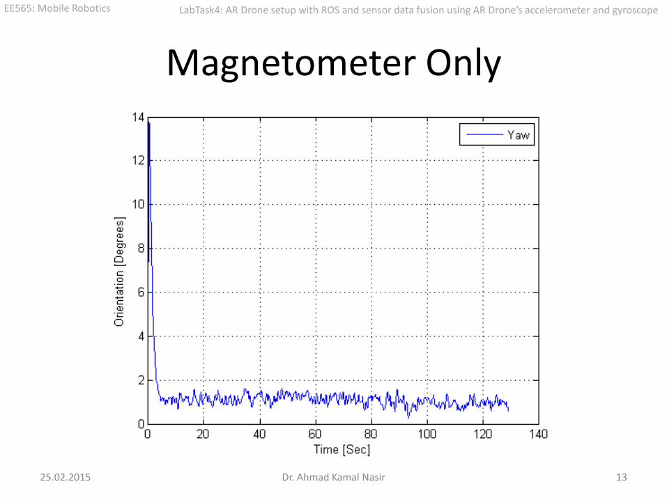
Yaw angle from magnetometer (Review)
𝑀𝑏 = 𝑅𝑥 𝜙 ∙ 𝑅𝑦 𝜃 ∙ 𝑅𝑧 𝜓 ∙ 𝑀𝑖 (𝑚𝑥) cos 𝜃 + (𝑚𝑦) sin 𝜙 sin 𝜃 + (𝑚𝑧)cos(𝜙)sin(𝜃)
(𝑚𝑦) cos 𝜙 − (𝑚𝑧)sin(𝜙)
−(𝑚𝑥) sin 𝜃 + (𝑚𝑦) sin 𝜙 cos 𝜃 + (𝑚𝑧)cos(𝜙)cos(𝜃)
=
𝐵 ∙ cos 𝛿 ∙ cos(𝜓)
−𝐵 ∙ cos 𝛿 ∙ sin(𝜓)
𝐵 ∙ sin 𝛿
𝑦 = 𝑚𝑦cos 𝜙 − 𝑚𝑧 sin 𝜙 𝑥 = 𝑚𝑥 cos 𝜃 + 𝑚𝑦 sin 𝜃 sin 𝜙 + 𝑚𝑧 sin 𝜃 cos 𝜙 𝜓 = −𝑎𝑡𝑎𝑛2(𝑦, 𝑥)
25.02.2015 Dr. Ahmad Kamal Nasir 7
EE565: Mobile Robotics LabTask4: AR Drone setup with ROS and sensor data fusion using AR Drone’s accelerometer and gyroscope
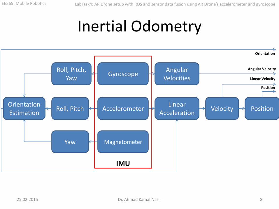
Inertial Odometry
25.02.2015 Dr. Ahmad Kamal Nasir 8
Gyroscope
Accelerometer
Roll, Pitch, Yaw
Roll, Pitch Velocity Position
Magnetometer Yaw
Orientation Estimation
Linear Acceleration
IMU
Angular Velocities
Orientation
Angular Velocity
Linear Velocity
Position

EE565: Mobile Robotics LabTask4: AR Drone setup with ROS and sensor data fusion using AR Drone’s accelerometer and gyroscope
Complementary Filter
𝜃𝑡 = 𝛼 ∙ 𝜃𝑡−1 + 𝜔𝑡 ∙ Δ𝑡 + 1 − 𝛼 ∙ 𝜃𝑎
Where 𝜃𝑡 = 𝐶𝑢𝑟𝑟𝑒𝑛𝑡 𝑒𝑠𝑡𝑖𝑚𝑎𝑡𝑒 𝜃𝑡−1 = 𝑃𝑟𝑒𝑣𝑖𝑜𝑢𝑠 𝑒𝑠𝑡𝑖𝑚𝑎𝑡𝑒 Δ𝑡 = 𝑆𝑎𝑚𝑝𝑙𝑖𝑛𝑔 𝑖𝑛𝑡𝑒𝑟𝑣𝑎𝑙 𝜃𝑎 = 𝐴𝑐𝑐𝑒𝑙𝑒𝑟𝑜𝑚𝑒𝑡𝑒𝑟 𝑚𝑒𝑎𝑠𝑢𝑟𝑒𝑚𝑒𝑛𝑡𝑠 𝜔𝑡 = 𝐺𝑦𝑟𝑜𝑠𝑐𝑜𝑝𝑒 𝑚𝑒𝑎𝑠𝑢𝑟𝑒𝑚𝑒𝑛𝑡𝑠 𝛼 = 𝑊𝑒𝑖𝑔𝑡𝑖𝑛𝑔 𝑐𝑜𝑛𝑠𝑡𝑎𝑛𝑡
25.02.2015 Dr. Ahmad Kamal Nasir 9

EE565: Mobile Robotics LabTask4: AR Drone setup with ROS and sensor data fusion using AR Drone’s accelerometer and gyroscope
Iterative Complementary Filter
Prediction
𝜃𝑡
+ = 𝜃𝑡−1 + 𝜔𝑡 ∙ Δ𝑡
Correction
𝜃𝑡 = 𝜃𝑡
+ + 𝛼 ⋅ 𝜃𝑎 − 𝜃𝑡+
25.02.2015 Dr. Ahmad Kamal Nasir 10
EE565: Mobile Robotics LabTask4: AR Drone setup with ROS and sensor data fusion using AR Drone’s accelerometer and gyroscope
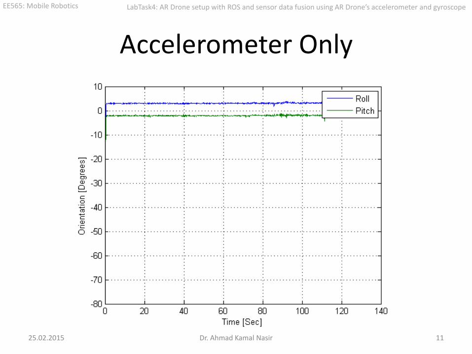
Accelerometer Only
25.02.2015 Dr. Ahmad Kamal Nasir 11

EE565: Mobile Robotics LabTask4: AR Drone setup with ROS and sensor data fusion using AR Drone’s accelerometer and gyroscope
Gyroscope Only
25.02.2015 Dr. Ahmad Kamal Nasir 12
EE565: Mobile Robotics LabTask4: AR Drone setup with ROS and sensor data fusion using AR Drone’s accelerometer and gyroscope
Magnetometer Only
25.02.2015 Dr. Ahmad Kamal Nasir 13

EE565: Mobile Robotics LabTask4: AR Drone setup with ROS and sensor data fusion using AR Drone’s accelerometer and gyroscope
Fused (Complementary Filter)
25.02.2015 Dr. Ahmad Kamal Nasir 14

EE565: Mobile Robotics LabTask4: AR Drone setup with ROS and sensor data fusion using AR Drone’s accelerometer and gyroscope
In-Lab Tasks • Start the AR Drone, make wireless connection, use ardrone/navdata topic to acquire sensor information.
• Write code for a node that reads the AR Drone navdata. You’ll get linear acceleration, gyro-rate and magnetometer readings about x, y and z axes.
• Now place the quadrotor in a static state. Ideally your IMU readings should give constant values.
• Estimate Euler angles (orientation) upon each callback (accelerometer + magnetometer):
– Using the linear acceleration (accelerometer) readings, find the Roll and Pitch angles (𝜙𝑎 , 𝜃𝑎). [See Class Lecture 6]
– Once you have the Roll and Pitch angles, find the Yaw angle (𝜓𝑚) using Magnetometer readings. [Slide 44]
• Use Gyro readings (𝑝, 𝑞, 𝑟) to get fused Euler angles (𝜙, 𝜃, 𝜓), upon each callback. Here you’d need values of (𝜙𝑎 , 𝜃𝑎, 𝜓𝑚) upon each iteration. Basically, implement the following equations (E.g. choose 𝛼 = 0.8) : [Slide 33]
𝜙𝜃𝜓
𝑡
= 𝛼𝜙𝜃𝜓
𝑡−1
+ 1 − 𝛼
𝜙𝑎𝑚
𝜃𝑎𝑚
𝜓𝑎𝑚 𝑡
𝑓𝑜𝑟 0 < 𝛼 < 1
𝜙𝜃𝜓
𝑡
=𝜙𝜃𝜓
𝑡−1
+
1 sin 𝜙 tan 𝜃 cos 𝜙 tan 𝜃0 cos 𝜙 − sin 𝜙0 sin 𝜙 / cos 𝜃 cos 𝜙 / cos 𝜃
𝑝𝑞𝑟
𝑡
𝛥𝑡
• 𝛥𝑡 can be found using timestamps.
• Publish fused Euler angles as an odometry message and visualize in RViz. Assume position to be 0, 0, 0 . Verify your implementation by moving and rotating the quadrotor by hand.
• Remember to record a bagfile having IMU data, it will be used in Lab Assignment.
25.02.2015 Dr. Ahmad Kamal Nasir 15

EE565: Mobile Robotics LabTask4: AR Drone setup with ROS and sensor data fusion using AR Drone’s accelerometer and gyroscope
Lab Assignment
• INERTIAL ODOMETRY • Estimate the position (pose) along the three axes from accelerometer:
– Convert the accelerometer readings from body frame to inertial frame. Use the Euler angles found in-Lab. [Lecture 6, Slide 22]
– Implement rectangular integration step to find linear velocities from linear accelerations (in inertial frame). You’d need to find 𝛥𝑡 using timestamps.
– Once you have linear velocities from accelerometer readings, find the position along the three axes by integration again.
• MEASUREMENT COVARIANCE • Estimate the covariance matrix for estimated Roll, Pitch and Yaw. For this,
run your code while keeping the robot in a static state. Record readings for about 60 seconds, and find all entries of the mean vector (3 x 1) and covariance matrix of the Euler angles statistically.
• Take a few different values of 𝛼 and see which gives most certain estimates.
25.02.2015 Dr. Ahmad Kamal Nasir 16

EE565: Mobile Robotics LabTask4: AR Drone setup with ROS and sensor data fusion using AR Drone’s accelerometer and gyroscope
Questions
25.02.2015 Dr. Ahmad Kamal Nasir 17