INDIAN OIL CORPORATION LTD. · 1.8.4 The materials, supplied by the Department shall be deemed to...
406
INDIAN OIL CORPORATION LTD. Marketing Division, Head Office Civil Work Specifications 2013 Volume - I
Transcript of INDIAN OIL CORPORATION LTD. · 1.8.4 The materials, supplied by the Department shall be deemed to...

INDIAN OIL CORPORATION LTD. Marketing Division, Head Office Civil Work Specifications 2013 Volume - I
00018005
Stamp

1 | P a g e H O C i v i l S p e c i f i c a t i o n s V o l u m e - I
CONTENTS (Vol.- I)
Sub Head NAME OF SUB-HEAD PAGE No.
1.0 GENERAL 04-06
2.0 EARTH WORK 07-39
3.0 MORTARS 40-54
4.0 CONCRETE WORK 55-81
5.0 REINFORCED CEMENT CONCRETE WORK 82-157
6.0 BRICK WORK 158-188
7.0 STONE WORK 189-223
8.0 MARBLE WORK 224-239
9.0 WOOD WORK AND PVC WORK 240-312
10.0 STEEL WORK 313-341
11.0 FLOORING 342-369
12.0 ROOFING 370-405

2 | P a g e H O C i v i l S p e c i f i c a t i o n s V o l u m e - I
1.0: GENERAL

3 | P a g e H O C i v i l S p e c i f i c a t i o n s V o l u m e - I
Clause No. Brief Description Page No
1.1 References 4
1.2 Rates 4
1.3 Interpretations 4
1.4 Floor and Levels 4
1.5 Special Structures 4
1.6 Foundations and Plinth 4-5
1.7 Measurements 5
1.8 Materials 5
1.9 Safety in Construction 5
1.10 Abbreviations 6

4 | P a g e H O C i v i l S p e c i f i c a t i o n s V o l u m e - I
0.0 GENERAL 1.1 Reference mentioned herein shall be appl icable to al l sections to the extent the context permits
and ar e i ntended t o s upplement t he pr ovisions i n t he par ticular s ection. I n c ase of any discrepancy/ deviation, the provisions in the particular section shall take precedence.
1.2 The rates for al l i tems of work unless clearly specified otherwise shall include cost of al l labour,
materials and other inputs involved in the execution of the items.
1.3 INTERPRETATIONS
1.3.1 Wherever any reference i s made to any Indian S tandard, i t shall be t aken as reference to the latest edition with al l amendments issued thereto. In the event of any variation between these specifications and the Indian Standard, the former shall take precedence over the latter.
1.3.2 IS: The standards, specification and code of practices issued by the Bureau of Indian Standards.
1.3.3 Best: The word ‘best’ when used shall mean that in the opinion of the Engineer-in-Charge, there is no superior material/ article and workmanship obtainable in the market and trade respectively. As far as possible the standard required shall be specified in preference to the word ‘best’.
1.4 FLOOR AND LEVELS 1.4.1 Building 1.4.1.1 Floor 1 is the lowest floor above the ground level in the building unless otherwise specified in a
particular case. The floors above floor 1 shall be numbered in sequence as floor 2, floor 3 and so on. The number shall increase upwards.
1.4.1.2 Floor level: For floor 1, top level of finished floor shall be the floor level and for all other floors above floor 1, top level of the structural slabs shall be the floor level.
1.4.1.3 Plinth level: Floor 1 level or 1.2 m above the ground level whichever is lower shall be the plinth level.
1.5 Special Structures 1.5.1 For structures like ret aining w alls, w ing w alls, c himneys, o ver he ad reservoirs/ tanks an d ot her
elevated structures, where elevations/ heights above a defined datum level have not been specified and identification of floors cannot be done as in case of building. Level, at 1.2 m above the ground level shall be the floor 1 level as well as plinth level. Level at a height of 3.5 m above floor 1 level will be reckoned as floor 2 level and level at a height of 3.5 m above the floor 2 level will be floor 3 level and so on, where the t otal hei ght abo ve floor 1 l evel i s not a w hole num ber multiple o f 3. 5 metre. T op m ost f loor level s hall be t he next i n sequence t o the floor level below e ven i f t he difference in height between the two upper most floor levels is less than 3.5 metres
1.6 FOUNDATION AND PLINTH The work in foundation and plinth shall include: (a) For buildings: All works upto 1.2 metre above ground level or upto floor 1 level whichever is lower: (b) For abutments, piers and well steining: all works upto 1.2 m above the bed level: (c) F or r etaining wall, wing w alls, c ompound walls, chimneys, over he ad r eservoirs/ tanks an d other elevated structures: All works upto 1.2 metre above the ground level: (d) F or res ervoirs/ t anks ( other t han ov erhead res ervoirs/ t anks): A ll works u pto 1. 2 m etre abov e the ground level:

5 | P a g e H O C i v i l S p e c i f i c a t i o n s V o l u m e - I
(e) For basements: All works upto 1.2 m above ground level or upto floor 1 level whichever is lower. Note: Specific provision shall be made in the estimate for such situations where the foundation level is more than 3 (three) metre depth from the plinth for all types of structures mentioned above.
1.7 MEASUREMENTS 1.7.1 In booking dimensions, the order shall be consistent and in the sequence of length, w idth and
height or depth or thickness.
1.7.2 Rounding off : Rounding off w here required shall be do ne in accordance with IS: 2-1960. The number of significant places rounded in the rounded off value should be as specified.
1.8 MATERIALS 1.8.1 Samples of all materials to be used on t he work shall be got approved by the contractor from the
Engineer-in-Charge well in time. The approved samples duly authenticated and sealed shall be kept in the custody of the Engineer-in-Charge till the completion of the work. All materials to be provided by the contractor shall be brand new and as per the samples approved by the Engineer-in-Charge.
1.8.2 Materials obtained by the contractor f rom the sources approved by the Corporation shall be
subjected t o t he M andatory t ests. Where s uch m aterials do no t conform t o t he re levant specifications, the matter shall be taken up by the Engineer-in-Charge for appropriate action against the defaulters. In all such cases, necessary documents in original and proof of payment relating to the procurement of materials shall be made available by the contractor to the Engineer-in-Charge.
1.8.3 Samples, whether submitted for approval to govern bulk supplies or required for testing before use and
also the sample of materials bearing ‘Standard mark,’ if required for testing, shall be provided free of cost by the contractor. All other incidental expenditure to be incurred for testing of samples e.g. packaging, sealing transportation, loading, unloading etc. except testing charges shall be borne by the contractor.
1.8.4 The materials, supplied by the Department shall be deemed to be complying with the specifications. 1.8.5 Materials stored at s ite, de pending u pon t he i ndividual c haracteristics, s hall be p rotected f rom
atmospheric effects due to rain, sun, wind and moisture to avoid deterioration. 1.8.6 Materials l ike timber, paints etc. shall be stored in such a w ay that there may not be an y possibility
of f ire hazards. I nflammable m aterials and ex plosives s hall be s tored i n accordance w ith t he relevant rules and regulations or as approved by Engineer-in-Charge in writing so as to ensure desired safety during storage.
1.8.7 The unit weight of materials unless otherwise specified shall be reckoned as given in IS: 1911-1967.
1.9 SAFETY IN CONSTRUCTION 1.9.1 The contractor shall employ only such methods of construction, tools and plant as are appropriate
for the type of work or as approved by Engineer-in-Charge in writing. 1.9.2 The contractor shall take al l precautions and m easures to ensure safety of works and w orkman
and s hall b e f ully r esponsible f or the s ame. S afety pe rtaining to c onstruction w orks such as excavation, centering and shuttering, t renching, bl asting, dem olition, el ectric c onnections, s caffolds, ladders, working platforms, gangway, mixing of bituminous materials, electric and gas welding, use of hoisting and construction machinery shall be governed by IOCL safety code, relevant safety codes and the direction of Engineer-in-Charge
6 | P a g e H O C i v i l S p e c i f i c a t i o n s V o l u m e - I
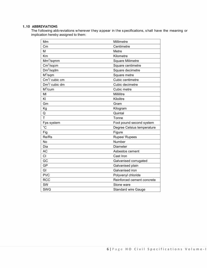
1.10 ABBREVIATIONS
The following abbreviations wherever they appear in the specifications, shall have the meaning or implication hereby assigned to them:
Mm Millimetre Cm Centimetre M Metre Km Kilometre Mm2/sqmm Square Milimetre Cm2/sqcm Square centimetre Dm2/sqdm Square decimetre M2/sqm Square metre Cm3/ cubic cm Cubic centimetre Dm3/ cubic dm Cubic decimetre M3/cum Cubic metre Ml Millilitre Kl Kilolitre Gm Gram Kg Kilogram Q Quintal T Tonne Fps system Foot pound second system °C Degree Celsius temperature Fig Figure Re/Rs Rupee/ Rupees No Number Dia Diameter AC Asbestos cement CI Cast Iron GC Galvanised corrugated GP Galvanised plain GI Galvanised iron PVC Polyvenyl chloride RCC Reinforced cement concrete SW Stone ware SWG Standard wire Gauge

7 | P a g e H O C i v i l S p e c i f i c a t i o n s V o l u m e - I
2.0: Earth Work

8 | P a g e H O C i v i l S p e c i f i c a t i o n s V o l u m e - I
CONTENTS
Clause No. Brief Description Page No.
List of Bureau of Indian Standard Codes 09 2.0 Definitions 10 2.1 Classification of Soils 10 2.2 Antiquities and Useful Materials 11 2.3 Protections 11 2.4 Site Clearance 11 2.5 Setting out and Making profiles 12 2.6 Blasting 12 2.7 Excavation in All kinds of soils 14 2.8 Excavation in Ordinary/ Hard rock 15 2.9 Earth work by mechanical means 16 2.10 Filling 18 2.11 Measurements 18 2.12 Rates 19 2.13 Surface Excavation 19 2.14 Rough Excavation and Filling 20 2.15 Excavation over Area (All kinds of Soil) 20 2.16 Excavation over Area (Ordinary/Hard rock) 20 2.17 Excavation in Trenches for Foundations and Drains (All kinds of Soil) 20 2.18 Excavation in Trenches for Foundation and Drains (Ordinary/ Hard rock) 21

9 | P a g e H O C i v i l S p e c i f i c a t i o n s V o l u m e - I
2.19 Excavation in Trenches for Pipes, Cables etc. and Refilling 21 2.20 Planking and Strutting 22 2.21 Excavation in Water, Mud or Foul position 23
2.22 Earth work for major works 24 2.23 Filling in Trenches, Plinth, under Floor etc. 25 2.24 Sand Filling in Plinth 25 2.25 Surface Dressing 26 2.26 Jungle Clearance 26 2.27 Felling Trees 27 2.28 Anti Termite Treatment 27 Fig. 2.1 The Design for Temporary Site Bench Mark 33 Fig. 2.2 Close and Open Planking and Strutting 34 Fig. 2.3 Anti-Termite Construction Stage 1 to 8 35 (i to viii) Fig. 2.4 Anti-Termite Construction - Final Recommendations 39
LIST OF BUREAU OF INDIAN STANDARD CODES
S. No. I.S . No. Subject 1 IS 632 Gamma - BHC (Lindane) emulsifiable concentrates 2 IS 1200 (Pt 1) Method of measurement of earth work 3 IS 1200 (Pt-27) Method of measurement of earth work (by Mechanical
Appliances ) 4 IS 4081 Safety code for Blasting and related drilling operation 5 IS 4988 (Part IV) Excavators 6 IS 6313 (pt-II) Anti Termite measures in buildings (pre -constructional) 7 IS 6313(pt.-III) Anti Termite Measures in Buildings for existing buildings 8 IS 6940 Methods of test for pesticides and their formulations 9 IS 8944 Chlorpyrifos emulsifiable concentrates 10 IS 8963 Chlorpyrifos - Technical specifications 11 IS 12138 Earth moving Equipments

10 | P a g e H O C i v i l S p e c i f i c a t i o n s V o l u m e - I
2.0 EARTH WORK
2.0 DEFINITIONS Deadmen or Tell Tales: Mounds of earth left undisturbed in pits dug out for borrowing earth
Burjis: Short pillars of br ick/ s tone having t op s urface f inished with c ement pl aster f or m arking et c.
Formation or Profile: Final shape of the ground after excavation or filling up.
Foul c ondition: Filthy an d unh ygienic c onditions w here ph ysical movements are h ampered s uch as s oil mixed with sewage or night soil.
Lead : All distances shall be measured over the shortest practical route and no t necessarily the rou te actually taken. R oute other than shortest practical route may be c onsidered in cases of unavoidable circumstances and approved by Engineer-in-charge along with reasons in writing.
Carriage by manual labour shall be reckoned in units of 50 metres or part thereof.
Carriage by animal and mechanical t ransport shall be reckoned in one km. unit. Distances of 0.5 km. or more shall be taken as 1 km. and distance of less than 0.5 km. shall be ignored. However, when the total lead is less than 0.5 km., it will not be ignored but paid for separately in successive stages of 50 metres subject to the condition that the rate worked on this basis does not exceed the rate for initial lead of 1 km. by mechanical/animal transport. Lift: The vertical distance for r emoval with reference to the ground level. The excavation up to 1 .5 metres depth below the ground level and depos iting the excavated materials upto 1.5 metres above the ground level are included in the rate of earth work. Lifts inherent in the lead due to ground slope shall not be paid for. Safety rules: Safety rules as laid down by the statutory authority and as provided in General Conditions of Contract shall be followed.
2.1 CLASSIFICATION OF SOILS 2.1.0 The earthwork shall be c lassified under the following categories and m easured separately f or each category:
(a) All kind of soils: Generally any strata, such as sand, gravel, loam, clay, mud, black cotton moorum, shingle, river or nallah bed boulders, siding of roads, paths etc. and hard core, macadam surface of any description (water bound, grouted tarmac etc.), lime concrete mud concrete and their mixtures which for excavation yields to application of picks, showels, jumper, sacrifiers, ripper and other manual digging implements. (b) Ordinary rock: Generally any rock which can be excavated by splitting with crow bars or picks and does not require blasting, wedging or similar means for excavation such as lime stone, sand stone, hard laterite, hard conglomerate and un-reinforced cement concrete below ground level.
If required l ight blasting may be resorted to for loosening the materials but this will not in any way entitle the material to be classified as ‘Hard rock’.
(c) Hard rock: Generally any rock or boulder for the excavation of which blasting is required such as quartzite, granite, basalt, reinforced cement concrete (reinforcement to be cut through but not separated from concrete) below ground level and the like.

11 | P a g e H O C i v i l S p e c i f i c a t i o n s V o l u m e - I
(d) Hard rock (blasting prohibited): Hard rock requiring blasting as described under (c) but where the blasting is prohibited for any reason and excavation has to be carried out by chiselling, wedging, use of rock hammers and cutters or any other agreed method.
2.2 ANTIQUITIES AND USEFUL MATERIALS 2.2.1 Any f inds of archaeological interest such as relics of antiquity, coins, fossils or other articles of value shall be delivered to the Engineer-in-Charge and shall be the property of the Government.
2.2.2 Any material obtained from the excavation which in the opinion of the Engineer-in-Charge is useful shall be stacked separately in regular stacks as d irected by the Engineer-in-Charge and shall be the property of the Corporation.
2.3 PROTECTIONS 2.3.1 Excavation where directed by the Engineer-in-Charge shall be securely barri caded and pro vided with proper caution signs, conspicuously displayed during the day and properly illuminated with red lights and/or written us ing fluorescent re flective pa int as directed by engineer in cha rge during the night to avoid accident. 2.3.2 The Contractor shall take adequate protective measures to see that the excavation operations do not damage the adjoining structures or dislocate the services. Water supply pipes, sluice va lve chambers, s ewerage pi pes, m anholes, dr ainage pipes and c hambers, c ommunication c ables, pow er supply cables e tc. met within the course of excavation shall be properly supported and adequately protected, so that these services remain functional. However, if any service is damaged during excavation shall be restored in reasonable time.
2.3.3 Excavation shall not be carried out below the foundation level of the adjacent bui ldings until underpinning, shoring etc. is done as per the di rections of the Engineer-in-Charge for which payment shall be made separately.
2.3.4 Any damages done by the contractor to any existing work shall be made good by him at his own cost. Existing drains pipes, culverts, over head w ires, water supply l ines and s imilar services encountered during the course of execution shall be protected against damage by the contractor. T he contractor shall not store material or otherwise occupy any part of the site in manner likely to hinder the operations of such services.
2.4 SITE CLEARANCE 2.4.1 Before the earth work is started, the area coming under cutting and fi lling shall be cleared of shrubs, rank vegetation, grass, brushwood, trees and saplings of girth up to 30cm measured at a height of one metre ab ove gr ound level an d rubbish removed up t o a distance of 50 metres out side the periphery of the area under c learance. The roots o f t rees and saplings shall be r emoved to a d epth o f 60cm below ground l evel or 30 c m below formation level or 15 c m below sub grade l evel, whichever is lower, and the holes or hollows filled up with the earth, rammed and levelled. 2.4.2 The trees of girth above 30 cm measured at a height of one metre above ground shall be cut only after permission of the Engineer-in-Charge is obtained in writing. The roots of trees shall also be removed as specified in 2.4.1. payment for cutting such t rees and removing the roots shall be m ade separately. 2.4.3 Existing structures and services such as old bu ildings, culverts, fencing, water supply pipe l ines, sewers, power cables, communication cables, drainage pipes etc. within or adjacent to the area if required to be diverted/removed, shall be diverted/dismantled as per directions of t he Engineer-in- Charge and payment for such diversion/dismantling works shall be made separately.

12 | P a g e H O C i v i l S p e c i f i c a t i o n s V o l u m e - I
2.4.4 In case of archaeological monuments within or adjacent to the area, the contractor shall provide necessary fencing all-round such monuments as per the di rections of the Engineer-in-Charge and pr otect the same properly during execution of works. Payment for providing fencing shall be made separately.
2.4.5 Lead of 50 m mentioned in the ‘Schedule Of Quantities’ is the average lead for the disposal of excavated earth within the site of work. T he actual lead for the lead for the disposal of earth may be more or less than the 50 m for which no cost adjustment shall be made in the rates.
2.4.6 Disposal of Earth shall be di sposed off at the specified location or a s decided by the Engineer-in- Charge. The contractor has to take written permission about place of disposal of earth before the earth is disposed off, from Engineer-in-Charge.
2.5 SETTING OUT AND MAKING PROFILES 2.5.1 A masonry pillar to serve as a bench mark will be erected at a suitable point in the area, which is visible from the largest area. This bench mark shall be constructed as per Fig. 2.1 and connected with the standard bench mark as approved by the Engineer-in-Charge. Necessary profiles with strings stretched on pegs, bamboos or ‘ Burjis’ shall be m ade to indicate the correct formation levels before the work is s tarted. The contractor shall supply labour and material for constructing bench mark, setting out and making profiles and connecting bench m ark with the s tandard bench mark at hi s own cost. The pegs, bamboos or ‘Burjis’ and t he bench mark shall be m aintained by the contractor at his own cost during the excavation to check the profiles. 2.5.2 The ground levels shall be taken at 5 to 15 metres intervals (as directed by the Engineer-in- Charge) in uni formly sloping ground and at closer intervals where local mounds, pi ts or undulations are met with. The ground levels shall be r ecorded in f ield books and pl otted on pl ans. The plans shall be drawn to a scale of 5 metres to one cm or any other suitable scale decided by the Engineer-in-Charge. North di rection l ine and pos ition of bench mark shall invariable be shown on the plans. These plans shall be signed by the contractor and the Engineer-in-Charge or their au thorized rep resentatives before the earth work is started. The labour required for taking levels shall be s upplied by the contractor at his own cost.
2.6 BLASTING 2.6.0 Where hard rock is met with and blasting operations are considered necessary, the contractor shall obtain the approval of the Engineer-in-Charge in writing for resorting to blasting operation.
Note: In ordinary rock blasting operations shall not be generally adopted. However, the contractor may resort to blasting with the permission of the Engineer-in-charge, but nothing extra shall be pai d for such blasting operations.
The contractor shall obtain license from the competent authority for undertaking blasting work as well as for obt aining and storing t he ex plosive as pe r t he E xplosive A ct, 1884 as am ended up to dat e and the Explosive Rules, 1983. The contractor shall purchase the explosives fuses, detonators, etc. only from a licensed dealer. The contractor shall be responsible for the safe transportation, storage and custody as per explosive rules and proper accounting of the explosive materials. Fuses and detonators shall be stored separately and away from the explosives. The Engineer-in-Charge or his authorized representative shall have the right to check the contractor’s store and account of explosives. The contractor shall provide necessary facilities for this.
The contractor shall be r esponsible for any damage ar ising out of accident to workmen, publ ic or property due to storage, transportation and use of explosive during blasting operation.
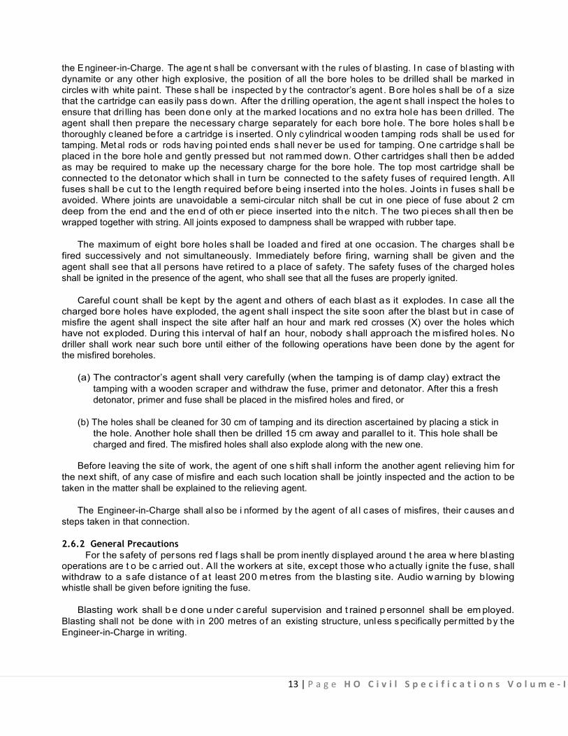
2.6.1 Blasting operations shall be c arried out under the supervision of a res ponsible authorized agent of the contractor (referred subsequently as agent only), during specified hours as approved in writing by
13 | P a g e H O C i v i l S p e c i f i c a t i o n s V o l u m e - I
the Engineer-in-Charge. The age nt s hall be c onversant w ith t he r ules o f blasting. I n case o f blasting w ith dynamite or any other high explosive, the position of all the bore holes to be drilled shall be marked in circles w ith white paint. These s hall be i nspected b y t he contractor’s agent . Bore holes s hall be o f a size that the cartridge can eas ily pass down. After the d rilling operat ion, the agent shall inspect the holes to ensure that dri lling has been done only at the marked locations and no extra hole has been drilled. The agent shall then prepare the necessary charge separately for each bore hole. The bore holes shall be thoroughly c leaned be fore a c artridge is i nserted. O nly c ylindrical wooden tamping rods shall be us ed for tamping. Metal rods or rods hav ing pointed ends s hall never be us ed for tamping. O ne c artridge s hall be placed in the bore hole and gently pressed but not rammed down. Other cartridges shall then be added as may be required to make up the necessary charge for the bore hole. The top most cartridge shall be connected to the detonator which shall in turn be connected to the safety fuses of required length. All fuses shall be cut to the length required before being inserted into the holes. Joints in fuses shall be avoided. Where joints are unavoidable a semi-circular nitch shall be cut in one piece of fuse about 2 cm deep from the end and the end of oth er piece inserted into the nitch. The two pieces shall then be wrapped together with string. All joints exposed to dampness shall be wrapped with rubber tape.
The maximum of eight bore holes shall be loaded and f ired at one occasion. The charges shall be fired successively and not simultaneously. Immediately before firing, warning shall be given and the agent shall see that all persons have retired to a place of safety. The safety fuses of the charged holes shall be ignited in the presence of the agent, who shall see that all the fuses are properly ignited.
Careful count shall be kept by the agent and others of each blast as it explodes. In case all the charged bore holes have exploded, the agent shall inspect the site soon after the blast but in case of misfire the agent shall inspect the site after half an hour and mark red crosses (X) over the holes which have not exploded. During this interval of hal f an hour, nobody shall approach the misfired holes. No driller shall work near such bore until either of the following operations have been done by the agent for the misfired boreholes.
(a) The contractor’s agent shall very carefully (when the tamping is of damp clay) extract the tamping with a wooden scraper and withdraw the fuse, primer and detonator. After this a fresh detonator, primer and fuse shall be placed in the misfired holes and fired, or
(b) The holes shall be cleaned for 30 cm of tamping and its direction ascertained by placing a stick in the hole. Another hole shall then be drilled 15 cm away and parallel to it. This hole shall be charged and fired. The misfired holes shall also explode along with the new one.
Before leaving the site of work, the agent of one s hift shall inform the another agent relieving him for the next shift, of any case of misfire and each such location shall be jointly inspected and the action to be taken in the matter shall be explained to the relieving agent.
The Engineer-in-Charge shall also be i nformed by the agent of al l cases of misfires, their causes and steps taken in that connection.
2.6.2 General Precautions For the safety of persons red f lags shall be prom inently displayed around t he area w here blasting
operations are t o be c arried out . All the workers at s ite, except those who actually ignite the fuse, shall withdraw to a safe d istance o f a t least 200 metres from the b lasting s ite. Audio warning by b lowing whistle shall be given before igniting the fuse.
Blasting work shall b e d one u nder c areful supervision and t rained p ersonnel shall be em ployed. Blasting shall not be done with in 200 metres of an existing structure, unless specifically permitted by the Engineer-in-Charge in writing.

14 | P a g e H O C i v i l S p e c i f i c a t i o n s V o l u m e - I
All p rocedures and safety p recautions for the use of explosives drilling and loading of explosives drilling and loading of explosives before and after shot firing and disposal of explosives shall be taken by the contractor as detailed in IS 4081, safety code for blasting and related drilling operation. 2.6.3 Precautions against Misfire
The safety fuse shall be cut in an ob lique direction with a knife. All saw dust shall be cleared from inside of the detonator. This can be done by blowing down the detonator and tapping the open end. No tools shall be inserted into the detonator for this purpose.
If there is water present or if the bore hole is damp, the junction of the fuse and detonator shall be made water tight by means of tough grease or any other suitable material.
The detonator shall be i nserted into the cartridge so that about one third of the copper tube is left exposed outside the explosive. The safety fuse just above the detonator shall be securely t ied in pos ition in the cartridge. Water proof fuse only shall be used in the damp bore hole or when water is present in the bore hole.
If a m isfire has been f ound to be due t o defective fuse, detonator or dynamite, the ent ire consignment from which the fuse detonator or dynamite was taken shall be got inspected by the Engineer-in-Charge or hi s aut horized r epresentative b efore r esuming th e blas ting or r eturning the consignment.
2.7 EXCAVATION IN ALL KINDS OF SOILS 2.7.1 All excavation operat ions manually or by mechanical means shall include excavation and ‘getting out’ the excavated materials. In case of excavation for t renches, basements, water tanks etc. ‘getting out’ shall include throwing the excavated materials at a distance of at least one metre or half the depth of excavation, whichever is more, clear off the edge of excavation. In all other cases ‘getting out’ shall include de positing the ex cavated m aterials a s s pecified. T he s ubsequent d isposal o f the ex cavated material shall be either stated as a separate item or included with the items of excavation stating lead.
2.7.2 During the excavation the natural drainage of the area shall be maintained. Excavation shall be done from top to bottom. Undermining or undercutting shall not be done.
2.7.3 In firm soils, the sides of the trenches shall be kept vertical upto a depth of 2 metres from the bottom. For g reater depths, the excavation p rofiles shall be w idened by al lowing s teps of 50 c ms on either s ide after every 2 metres from the bottom. Alternatively, the excavation can be done so as to give slope of 1:4 (1 horizontal : 4 vertical). Where the soil is soft, loose or slushy, the width of steps shall be suitably increased or sides sloped or the soil shored up as directed by the Engineer-in- Charge. It shall be the responsibility of the contractor to take complete instructions in writing f rom the Engineer-in-Charge regarding the stepping , s loping or shoring to be done for excavation deeper than 2 metres.
2.7.4 The excavation shall be done true to levels, slope, shape and pat tern indicated by the Engineer-in- Charge. Only the excavation shown on the drawings with additional allowances for centering and shuttering or as required by the Engineer-in-Charge shall be measured and recorded for payment. 2.7.5 In case of excavation for foundation in trenches or over areas, the bed of excavation shall be to the correct l evel or s lope and consolidated by watering and ramming. I f t he excavation for foundation i s done to a dep th greater than that shown in the drawings or as required by the Engineer-in-Charge, the excess depth shall be made good b y the contractor at his own cost with the concrete of the mix used for levelling/ bed concrete for foundations. Soft/defective spots at the bed of t he foundations s hall be d ug out and filled with concrete (to be paid separately) as directed by the Engineer-in-Charge.

15 | P a g e H O C i v i l S p e c i f i c a t i o n s V o l u m e - I
2.7.6 While carrying out the excavation for drain work care shall be taken to cut the side and bot tom to the required shape, s lope and gradient. The surface shall then be properly dressed. I f the excavation is done to a dept h grea ter than that shown on t he drawing or as required by the Engineer-in-Charge, the excess depth shall be made good by the contractor at his own cost with stiff clay puddle at places where the drains are required to be pitched and with ordinary earth, properly watered and rammed, where the drains are not required to be pitched. In case the drain is required is to be pitched, the back filling with clay puddle, i f requ ired, shall be done simultaneously as the p itching work p roceeds. The brick pi tched storm water drains should be avoided as far as possible in filled-up areas and loose soils. 2.7.7 In all other cases where the excavation is taken deeper by the contractor, it shall be brought to the required level by the contractor at his own cost by f illing in with ear th duly watered, consolidated and rammed. 2.7.8 In case the excavation is done wider than that shown on the drawings or as required by the Engineer-in-Charge, additional filling wherever required on the account shall be done by the contractor at his own cost. 2.7.9 The excavation shall be done manually or by mechanical means as directed by Engineer-in-charge considering feasibility, ur gency of work, availability of l abour /mechanical eq uipments and other factors involved. C ontractor shall ensure every safety measures for the workers. Neither any deduction will be made nor any extra payment will be made on this account.
2.8 EXCAVATION IN ORDINARY/HARD ROCK 2.8.1 All excavation op erations s hall include ex cavation an d ‘ getting out’ t he ex cavated m atter. I n c ase of excavation for trenches, basements, water tanks etc. ‘getting out’ shall include throwing the excavated materials at a distance of at least one metre or half the depth of excavation, whichever is more, clear off the edge or excavation. In all other cases ‘getting out’ shall include depositing the excavated materials as specified. The subsequent disposal of the excavated material shall be ei ther stated as a separate item or included with the item of excavation stating lead. 2.8.2 During the excavation, the natural drainage of the area shall be maintained. Excavation shall be done from top to bottom. Undermining or under cutting shall not be done. 2.8.3 Where hard rock is met with and blasting operations are considered necessary, the contractor shall obtain the approval of the Engineer-in-Charge in writing for resorting to the blasting operations. B lasting operations shall be done as specified in Para 2.6 and chiselling shall be done to obtain correct levels, slopes, shape and pattern of excavation as per the drawings or a s requi red by the Engineer-in-Charge and nothing extra shall be payable for chiselling. 2.8.4 Where blasting operations are prohibited or are not practicable, excavation in hard rock shall be done by chiselling. 2.8.5 In ordinary rock excavation shall be c arried out by crowbars, pick axes or pneumatic drills and blasting operation shall not be gene rally adopted. Where blasting operations are not prohibited and i t i s practicable to resort to blasting for excavation in ordinary rock, contractor may do so with the permission of the Engineer-in-Charge in writing but nothing extra shall be paid for this blasting. Blasting shall be done as specified in Para 2.6. 2.8.6 If the excavation for foundations or drains is done to a depth greater than that shown in the drawings or as required by the Engineer-in-Charge. The excess depth shall be made good by the contractor at his own cost with the concrete of the mix used for levelling/ bed concrete for foundations. Soft/ defective spots at the bed of foundations shall be dug out and fi lled with concrete (to be paid separately) as directed by the Engineer-in-Charge.
16 | P a g e H O C i v i l S p e c i f i c a t i o n s V o l u m e - I
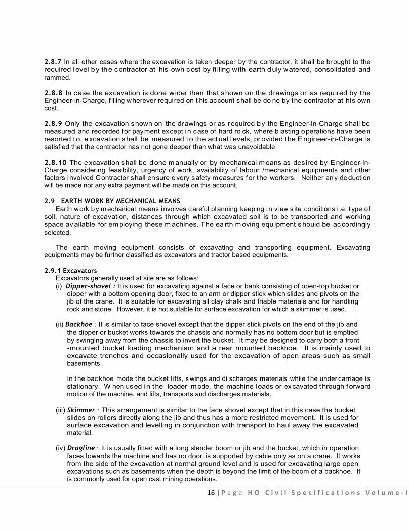
2.8.7 In all other cases where the excavation is taken deeper by the contractor, it shall be brought to the required level by the contractor at his own cost by fil ling with earth duly watered, consolidated and rammed.
2.8.8 In case the excavation is done wider than that shown on the drawings or as required by the Engineer-in-Charge, f illing wherever required on t his account shall be do ne by the contractor at his own cost.
2.8.9 Only the excavation shown on the drawings or as required by the Engineer-in-Charge shall be measured and recorded for payment except in case of hard ro ck, where b lasting operations have been resorted t o, excavation shall be measured to the actual l evels, provided the Engineer-in-Charge i s satisfied that the contractor has not gone deeper than what was unavoidable. 2.8.10 The excavation shall be done manually or by mechanical means as des ired by Engineer-in- Charge considering feasibility, urgency of work, availability of labour /mechanical equipments and other factors involved Contractor shall ensure every safety measures for the workers. Neither any deduction will be made nor any extra payment will be made on this account. 2.9 EARTH WORK BY MECHANICAL MEANS
Earth work by m echanical means involves careful planning keeping in v iew s ite conditions i .e. t ype of soil, nature of excavation, distances through which excavated soil is to be transported and working space av ailable for em ploying these m achines. T he ea rth m oving equ ipment s hould be ac cordingly selected.
The earth moving equipment consists of excavating and transporting equipment. Excavating equipments may be further classified as excavators and tractor based equipments. 2.9.1 Excavators
Excavators generally used at site are as follows: (i) Dipper-shovel : It is used for excavating against a face or bank consisting of open-top bucket or dipper with a bottom opening door, fixed to an arm or dipper stick which slides and pivots on the jib of the crane. It is suitable for excavating all clay chalk and friable materials and for handling rock and stone. However, it is not suitable for surface excavation for which a skimmer is used.
(ii) Backhoe : It is similar to face shovel except that the dipper stick pivots on the end of the jib and the dipper or bucket works towards the chassis and normally has no bottom door but is emptied by swinging away from the chassis to invert the bucket. It may be designed to carry both a front
-mounted bucket loading mechanism and a rear mounted backhoe. It is mainly used to excavate trenches and occasionally used for the excavation of open areas such as small basements.
In t he bac khoe mode t he buc ket l ifts, s wings and di scharges materials while t he under carriage i s stationary. W hen used in the ‘ loader’ mode, the machine loads or excavated through forward motion of the machine, and lifts, transports and discharges materials.
(iii) Skimmer : This arrangement is similar to the face shovel except that in this case the bucket slides on rollers directly along the jib and thus has a more restricted movement. It is used for surface excavation and levelling in conjunction with transport to haul away the excavated material. (iv) Dragline : It is usually fitted with a long slender boom or jib and the bucket, which in operation faces towards the machine and has no door, is supported by cable only as on a crane. It works from the side of the excavation at normal ground level and is used for excavating large open excavations such as basements when the depth is beyond the limit of the boom of a backhoe. It is commonly used for open cast mining operations.

17 | P a g e H O C i v i l S p e c i f i c a t i o n s V o l u m e - I
(v) Clamshell : It consists of two hinged half-buckets or jaws pivoted to a frame which is suspended by cable from a long jib of an excavation. The grab is used for deep excavations of limited area on all types of soil except rock. Crane and Grab is a variant of this type of equipment.
2.9.2 Tractor-based Equipment It is a self-propelled crawler or wheeled machine used to exert a pus h or pul l force through
mounted equipment. I t i s designed ei ther as attachments to normal t racked or wheeled t ractors or as machines in which the ear th moving at tachments and the t ractor are designed as a s ingle integrated unit. A tractor, which is hydraulically operated, can be rigged as :
(i) Loaders : It is used for loading, light dozing, scraping and grabbing operations, lifting and transporting the materials (loose earth, rubble, sand, gravel aggregate etc) at various sites through forward motion of the machine.
(ii) Tractor Shovel : This consists of a tipping bucket at the front attached by strong pivoted arms or booms to the frame of the machine. It is used for stripping top soil, excavating against a face, bulldozing and for loading spoil or loose materials. It is similar to crawler dipper-shovel.
(iii) Trench D igger : It operates on the same principle as a backhoe excavator except that the bucket is controlled by hydraulic rams instead of cables and pulleys. (iv) Scraper : Scrapers provide unique capability to excavate, load, haul and dump materials. Scrapers are available in various capacities by a number of manufacturers with options such as self - loading with elevators, twin engines or push-pull capability. They are cost effective where the haul distance is too long for bulldozers, yet too short for trucks. This distance typically ranges from 120 m to 1200 m; however, the economics should be evaluated for each project.
Scraper has an open bowl with a cutting edge positioned between the axles, which cuts, loads, transports, di scharges and s preads t hrough f orward m otion of t he machine. Loadi ng t hrough forward motion of the machine c an be assisted by a pow ered mechanism (elevator) f ixed to the scraper bowl.
(v) Bulldozer and Angle-dozer : The most common equipment used for clearing and levelling activities is a bulldozer. The terms bulldozer is used to define a tractor mounted with a dozing blade.
The bulldozer consists o f a r ectangular steel b lade with renewable cutting edge set at right angles (capable of only tilting but not angling) to the direction of travel and attached by steel arms to the side frames of a crawler tractor. It may be used for excavating natural soil or for moving loose soil or debris, which is pushed forward as the tractor forces it ahead.
(vi) Angledozer is capable of both tilting and angling
2.9.3 Transporting Equipment This implies horizontal movement primarily but it can involve some vertical movement too.
(i) Dumpers : These are self-propelled wheeled machines, having an open body. It is designed for the transport of excavated materials and consists of a shallow tipping hopper or skip mounted on a wheeled chassis, such as, power barrow, dumper, multi-skip dumpers, high discharge dumpers, dump truck, etc. These can be rear dump, side dump or bottom dump.
(ii) Vibratory Roller : It is a single Drum Vibratory Roller for compaction of embankments, etc. The smooth drum version is for compaction of granular and mixed soil. The sheepsfoot Roller consists of a hallow cylindrical steel drum or drums on which projecting feet are mounted. These

18 | P a g e H O C i v i l S p e c i f i c a t i o n s V o l u m e - I
feet penetrate into the fill as a rol ler moves forward and c ause compaction. T he geometry of the foot may be sheep, club pyramid, cone or cylinder foot. Such rollers are employed for compaction (densification) of cohesive and semi-cohesive soils.
2.10 FILLING 2.10.1 The earth used for f illing shall be f ree from all roots, grass, shrubs, rank vegetation, brushwood, tress, sapling and rubbish. 2.10.2 Filling with excavated earth shall be done in regular horizontal layers each not exceeding 20 cm in depth. All lu mps an d cl ods ex ceeding 8 cm i n a ny dir ection sh all b e br oken. E ach l ayer sh all be watered and consolidated with s teel rammer or ½ tonne roller. Where specified, every third and top must layer shall also be consolidated with power roller of minimum 8 tonnes. Wherever depth of filling exceeds 1.5 metre vibratory power roller shall be used to consolidate the filing unless otherwise directed by Engineer-in-charge. The top and sides of filling shall be neatly dressed. The contractor shall make good all subsidence and shrinkage i n ear th fillings, e mbankments, t raverses e tc. dur ing ex ecution and till t he completion of work unless otherwise specified.
2.11 MEASUREMENTS 2.11.1 The length and breadth of excavation or filling shall be measured with a s teel tape correct to the nearest cm. The depth of cutting or height of f illing shall be m easured, correct to 5 m m, by recording levels before the start of the work and af ter the completion of the work. The cubical contents shall be worked out to the nearest two places of decimal in cubic metres. 2.11.1.1 In case of open footings up to the depth of 1.5 metres, all-round excavation of 30 cm. beyond the outer dimension of footing shall be measured for payment to make al lowances for centering and shuttering. Any additional excavation beyond this l imit shall be at the risk and cost of the contractor and shall not be measured for payment. 2.11.1.2 In case of open footings/Rafts at a depth of more than 1.5 metre, all-round excavation of 75 cm shall be measured f or pa yment to m ake al lowance for c entering and s huttering. Additional ex cavation beyond this limit shall be at the risk and cost of the contractor and shall not be measured for payment. 2.11.2 In case the ground is fairly uniform and where the site is not required to be levelled, the Engineer-in-Charge may permit the measurements of depth of cutting or height of f illing w ith s teel tape, correct to the nearest cm. In case of bor row pi ts, diagonal r idges, c ross ridges or dead-men, the position of which shall be f ixed by the Engineer-in-Charge, shall be left by the contractor to permit accurate measurements being taken with steel tape on the c ompletion of the work Deduction of such ridges and dead men shall be made from the measurements unless the same are required to be removed later on and the earth so removed is ut ilized in the work. In the latter case nothing extra will be paid for their removal as subsequent operation. 2.11.3 Where ordinary rock and hard rock is mixed. The measurement of the excavation shall be made as specified i n 2. 11.1 and 2.11.2 T he t wo k inds of r ock s hall be s tacked s eparately and m easured i n stacks. The net quant ity of the two kinds of rocks shall be ar rived at by applying deduction of 50% to allow for voids in stacks. If the sum of net quantity of two kinds of rocks exceeds the total quantity of the excavated material, then the quantity for each type of rock shall be worked out from the total quantity in the ratio of net quan tities in stack m easurements o f the two types o f rocks. If in the op inion of t he Engineering-in-charge stacking is not feasible, the quantity of ordinary and hard rock shall be worked out by means of cross-sectional measurements. 2.11.4 Where soil, ordinary rock and hard rock are mixed, the measurements for the ent ire excavation shall be made as specified in 2.11.1 and 2.11.2 Excavated materials comprising hard rock and ordinary rock shall be stacked separately, measured, and each reduced by 50% to allow for voids to arrive at the
19 | P a g e H O C i v i l S p e c i f i c a t i o n s V o l u m e - I
quantity payable under hard rock and ordinary rock. The difference between the entire excavation and the sum of t he quantities payable und er ha rd rock and or dinary roc k shall be pa id for as ex cavation in ordinary soil or hard soil as the case may be. 2.11.5 Where it is not possible or convenient to measure the depth of cutting by recording levels as specified in 2.11.1 quantity of excavation s hall b e worked out from f illing. The ac tual measurements of the fill shall be calculated by taking levels of the original ground before start of the work after site clearance and after compaction of the fill as specified and the quantity of earth work so computed shall be reduced by 10% in case of consolidated fills and by 5% in case the consolidation is done by heavy mechanical machinery to arrive at the net quant ity of excavation for payment. No such deduction shall, however, be made in case of consolidation by heavy mechanical machinery at optimum moisture content, or when the consolidated filling is in confined situations such as under floors.
2.11.6. Recording Measurements for Earth Levelling Work
2.11.6.1 Level Books: In case of levelling operations and earthwork, measurements are required to be recorded in level books in addition to Measurement Books. The Level Books should be numbered, accounted for and handled like Measurement Books. 2.11.6.2 Preparatory Works: Before starting the earth work, following steps should be taken :
(1) Original ground levels should be recorded in the Level Book in the presence of the contractor or his authorized representative, and should be signed by him and the site engineer who records the levels.
(2) Plans showing initial levels, location of bench marks and reduced levels, should be prepared and signed by both the parties and at tached to the agreement before commencement of the work.
2.11.6.3 Final Levels (1) On completion of work, the levels should again be recorded in the Level Book and the contractor’s signatures obtained. (2) The formation levels as per f inal execution of the work should be c ompared with the proposed formation levels and the work got rectified within permissible tolerance.
2.12 RATES 2.12.1 Rates for Earthwork shall include the following:
(a) Excavation and depositing excavated material as specified. (b) Handing of antiquities and useful material as specified on 2.2. (c) Protection as specified in 2.3. (d) Site clearance as specified in 2.4. (e) Setting out and making profiles as specified in 2.5. (f) Forming (or leaving) dead - men or ‘Tell Tales’ in borrow pits and their removal after
measurements. (g) Bailing out or pumping of rain water from excavations. (h) Initial lead of 50 m and lift of 1.5 m. (i) Blasting operations for hard rock as specified in 2.6.
2.12.2 No deduction shall be m ade from the rate if in the opinion of the Engineer- in-charge, operations specified in 2.12.1 (b) to (h) are not required to be carried out on any account whatsoever.
2.13 SURFACE EXCAVATION 2.13.1 Excavations exceeding 1.5 m in width and 10 sqm. on plan but not exceeding 30 cm. in depth in all types of soils and rocks shall be described as surface excavation and shall be done as specified in 2.7 and 2.8.

20 | P a g e H O C i v i l S p e c i f i c a t i o n s V o l u m e - I
2.13.1 Measurements
The length and breadth shall be measured with a s teel tape correct to the nearest cm. and the area worked out to the nearest two places of decimal in square metres.
2.13.3 Rate shall be as specified in 2.12.
2.14. ROUGH EXCAVATION AND FILLING 2.14.1 Excavation for earth from borrow pits, cutting hi ll side slopes etc. shall be described as rough excavation and shall be done as specified in 2.7, 2.8 and 2.9. 2.14.2 Wherever f illing is to be done, the earth from excavation shall be directly used for filling and no payment for double hand ling of ear th shall be adm issible. F illing of excavated earth shall be done as specified in 2.10. In case of hill side cutting, where the excavated materials is thrown down the hill slopes, payment for filling excavated earth shall not be admissible.
2.14.3 Measurements shall be as specified in 2.11.
2.14.4 Rates shall be as specified in 2.12.
2.15 EXCAVATION OVER AREA (ALL KINDS OF SOIL) 2.15.1 This shall comprise:
(a) Excavation exceeding 1.5 m in width and 10 sqm on plan and exceeding 30 cm in depth. (b) Excavation for basements, water tanks etc. (c) Excavation in trenches exceeding 1.5 m in width and 10 sqm on plan.
2.15.2 Excavation shall be done as specified in 2.7.
2.15.3 Measurements shall be as specified in 2.11.
2.15.4 Rates shall be as specified in 2.12.
2.16 EXCAVATION OVER AREA (ORDINARY/ HARD ROCK) 2.16.1 This shall comprise:
(a) Excavation exceeding 1.5 m in width and 10 sqm on plan and exceeding 30 cm in depth. (b) Excavation for basements, water tanks etc. (c) Excavation in trenches exceeding 1.5 m in width and 10 sqm on plan.
2.16.2 Excavation shall be done as specified in 2.8 and 2.9.
2.16.3 Measurements shall be done as specified in 2.11.
2.16.4 Rates shall be as specified in 2.12.
2.17 EXCAVATION IN TRENCHES FOR FOUNDATIONS AND DRAINS (ALL KINDS OF SOIL) 2.17.1 This shall comprise excavation not exceeding 1.5 m in width or 10 sqm on plan and to any depth in trenches (excluding trenches for pipes, cables, conduits etc.)
2.17.2 Excavation shall be done as specified in 2.7.
2.17.3 Measurements shall be as specified in 2.11.
2.17.4 Rates shall be as specified in 2.12.

21 | P a g e H O C i v i l S p e c i f i c a t i o n s V o l u m e - I
2.18 EXCAVATION IN TRENCHES FOR FOUNDATION AND DRAINS (ORDINARY/ HARD ROCK) 2.18.1 This shall comprise excavation not exceeding 1.5m in width or 10 sqm. On plan and to any depth in trenches (excluding trenches for pipes, cables, conduits etc.)
2.18.2 Excavation shall be done as specified in 2.8. and 2.9.
2.18.3 Measurements shall be as specified in 2.11.
2.18.4 Rates shall be as specified in 2.12.
2.19 EXCAVATION IN TRENCHES FOR PIPES, CABLES ETC. AND REFILLING 2.19.1 This shall comprise excavation not exceeding 1.5 mts in width or 10 sqm in plan and to any depth t renches for pipes. Cables etc. and r eturning the excavated material to f ill the t renches after pipes, cables etc. are laid and their joints tested and passed and disposal of surplus excavated material upto 50 m lead.
2.19.2 Width of Trench (a) Upto one metre depth the authorized width of trench for excavation shall be arrived at by adding
25 cm to the ex ternal diameter of pipe (not socket/ collar) cable, conduit etc. Where a pipe is laid on concrete bed/ cushioning layer, the authorized w idth shall be the ex ternal diameter of pipe (not socket/ collar) plus 25 cm or the width of concrete bed/ cushioning layer whichever is more.
(b) For depths exceeding one metre, an allowance of 5 cm per metre of depth for each side of the trench shall be added to the authorized width (that is external diameter of pipe plus 25 cm) for excavation. This allowance shall apply to the entire depth of the trench. In firm soils the sides of the trenches shall be kept vertical upto depth of 2 metres from the bottom. For depths greater than 2 metres, the excavation profiles shall be widened by allowing steps of 50 cm on either side after every two metres from bottom. (c) Where more than one pipe, cable, conduit etc, are laid, the diameter shall be r eckoned as the horizontal distance from outside to outside of the outermost pipes, cable, conduit etc. (d) Where the soil is soft, loose or slushy, width of trench shall be suitably increased or side sloped or the soil shored up as directed by the Engineer-in-Charge. It shall be the responsibility of the contractor to take complete instructions in writing from the Engineer-in-Charge regarding increase in the width of trench. Sloping or shoring to be done for excavation in soft, loose or slushy soils.
2.19.3 Excavation : Shall be done as specified in 2.7, 2.8 and 2.9.
2.19.4 Refilling Filling in t renches shall be commenced soon after the joints of pipes, cables, conduits etc. have been
tested and passed. The space all-round the pipes, cables conduits etc. shall be cleared of all debris, brick bats etc. Where the trenches are excavated in hard/ soft soil, the filling shall be done with earth on the side and top of pipes in layers not exceeding 20 cm in depth. Each layer shall be watered, rammed and consolidated. A ll c lods and lumps of earth exceeding 8 c m in any di rection shall be broken or rem oved before the excavated earth is used for f illing. In case of excavation trenches in ordinary/ hard rock, the filling upto a depth of 30cm above the crown of pipe, cable, conduits etc. shall be done w ith fine material like earth, moorum or pulverized/ decomposed rock according to the availability at s ite. The remaining filling shall be do ne with boulders of s ize not exceeding 15cm mixed with f ine material l ike decomposed rock, moorum or earth as available to fill up the voids, watered, rammed and consolidated in layers not exceeding 30 cm. E xcavated m aterial c ontaining d eleterious m aterial, s alt pe ter ear th et c. s hall no t be used for f illing. Ramming shall be done with i ron rammers where feasible and with b lunt ends of crow bars where rammers cannot be used. Special care shall be taken to ensure that no damage is caused to the pipes, Cables, Conduits etc. laid in the trenches.

22 | P a g e H O C i v i l S p e c i f i c a t i o n s V o l u m e - I
2.19.5 Measurements 2.19.5.1 Trenches for pipes, cables, conduits etc. shall be measured in running metre correct to the nearest cm in stages of 1.5 m depth and described separately as under:
(a) Pipes, cables, conduits, etc. not exceeding 80 mm dia.
(b) Pipes, cables, conduits etc. exceeding 80 mm dia but not exceeding 300mm dia. (c) Pipes, cables, conduits etc. exceeding 300 mm dia.
2.19.5.2 Where two or more categories of each work are involved due to different classification of soil within the same stage of trench depth or w here the soil is soft loose or s lushy requiring increase in the width of trench or sloping sides or shoring, trenches for pipes, cables, conduits, etc. shall be measured in cubic m etres as s pecified i n 2. 10. E xtra ex cavation, i f any , on ac count of c ollar/ s ocket of pi pes s hall neither be measured nor paid for separately.
2.19.6 Rates The rate shall be as specified in 2.12 and shall also include the cost of refilling and all other
operations described above.
2.20 PLANKING AND STRUTTING 2.20.1 When the depth of trench in soft/loose soil exceeds 2 m etres, stepping, sloping and/ or pl anking and strutting of sides shall be done. In case of loose and slushy soils, the depths at which these precautions are t o be t aken, shall b e determined b y the Engineer-in-Charge according to the nature of soil.
Planking and s trutting shall be ‘close’ or ‘open’ depending on the nature of soil and the depth of trench. The type of planking and strutting shall be determined by the Engineer-in-Charge. I t shall be t he responsibility o f the c ontractor to take al l nec essary s teps to prevent t he s ides of trenches f rom collapse. Engineer-in-Charge should take guidance from IS: 3764 for designing the shoring and strutting arrangements and specifying the profile of excavation. 2.20.2 Close Planking and Strutting
Close planking and s trutting shall be done by completely covering the s ides of the trench genera lly with short upright, members called ‘poling boards’. These shall be 250x38 mm in section or as directed by the Engineer-in-Charge.
The boards shall generally be placed in position vertically in pairs. One boards on either side of cutting. These shall be kept apar t by horizontal wallings of s trong wood at a maximum spacing of 1.2 metres cross strutted with b allies, or a s di rected by Engineer-in-Charge. The length and diameter of the ba llies s trut shall depend upon the width of the trench. Typical sketch of close timbering is given in Fig. 2.2.
Where the soil is very soft and l oose, the boards shall be pl aced horizontally against the sides of the excavation and s upported by vertical ‘wallings’ which shall be s trutted to similar timber pieces on t he opposite face of the trench. The lowest boards supporting the s ides shall be taken in the ground for a minimum depth of 75 mm. No portion of the vertical side of the trench shall remain exposed.
The withdrawal of the timber members shall be done very carefully to prevent collapse of the trench. It shall be started at one end and proceeded systematically to the other end. Concrete or masonry shall not be damaged while removing the planks. No claim shall be e ntertained for any timber which cannot be withdrawn and is lost or buried, unless requ ired by the Engineer-in-Charge to be l eft permanently in position.
2.20.3 Open Planking and Strutting In case of open planking and strutting, the entire surface of the side of the trench is not required to be
covered. The vertical boards 250 mm wide & 38 mm thick, shall be spaced sufficiency apart to leave unsupported s trips of 50 cm average width. The detailed a rrangement, si zes of the timber and the distance apart shall be subject to the approval of the Engineer-in-Charge. In all other respect,

23 | P a g e H O C i v i l S p e c i f i c a t i o n s V o l u m e - I
specifications for close planking and s trutting shall apply to open pl anking and strutting. Typical sketch of open planking and strutting is given in fig. 2.2.
2.20.4 Measurements The dimensions shall be measured correct to the nearest cm and the area of the face supported
shall be worked out in square metres correct to two places of decimal.
2.20.4.1 Works shall be grouped according to the following: (a) Depth not exceeding 1.5 m. (b) Depth exceeding 1.5m in stages of 1.5 m.
2.20.4.2 Planking and strutting to the following shall be measured separately: (a) Trenches. (b) Areas- The description shall include use and waste of raking shores. (c) Shafts, walls, cesspits, manholes and the like (d) Where tightly driven close but jointed sheeting is necessary as in case of running sheeting is necessary as in case of running sand the item shall be measured separately and packing of cavities behind sheeting with suitable materials included with the item. (e) Planking and strutting required to be left permanently in position shall be measured separately.
2.20.5 Rates Rates shall include use and waste of al l necessary t imber work as mentioned above including f ixing
and subsequent removal.
2.21 EXCAVATION IN WATER. MUD OR FOUL POSITION 2.21.1 All water that may accumulate in excavations during the progress of the work from springs, tidal or river seepage, broken water mains or drains (not due to the negligence of the contractor), and seepage from subsoil aquifer shall be bailed, pumped out or otherwise removed. The contractor shall take adequate measures for bailing and/or pumping out water from excavations and/or pumping out water f rom excavations and construct diversion channels, bunds, sumps, coffer dams etc. as may be required. Pumping shall be done directly from the foundation trenches or from a sump out s ide the excavation in such a manner as to preclude the possibility o f movement o f water through any fresh concrete or masonry and washing away parts of concrete or mortar. During laying of concrete or masonry and for a period of at least 24 hours thereafter, pumping shall be done f rom a suitable sump separated from concrete or masonry by effective means.
Capacity and number of pumps, location at which the pumps are to be installed, pumping hours etc. shall be decided from time to time in consultation with the Engineer-in-Charge.
Pumping shall be done in such a way as not to cause damage to the work or adjoining property by subsidence etc. D isposal of water shall no t cause inconvenience or nu isance in the area or cause damage to the property and structure nearby.
To prevent slipping of sides, planking and strutting may also be done with the approval of the Engineer-in-Charge.
2.21.2 Classification The earth work for various classification of soil shall be categorised as under: (a) Work in or under water and/or liquid mud: Excavation, where water is met with from any of the sources specified in 2.21.1 shall fall in this category. Steady water level in the trial pits before the commencement of bailing or pumping operations shall be the sub-soil water level in that area. (b) Work in or under foul position: Excavation, where sewage, sewage gases or foul conditions are met with from any source, shall fall in this category. Decision of the Engineer-in-Charge whether the work is in foul position or not shall be final.

24 | P a g e H O C i v i l S p e c i f i c a t i o n s V o l u m e - I
2.21.3 Measurements 2.21.3.1 The unit, namely, metre depth shall be the depth measured from the level of foul position/ subsoil water level and upto the centre of gravity of the cross sectional area o f excavation actually done in the conditions c lassified in 2.21.2. Metre depth shall be rec koned correct to 0.1 m, 0.05 m or more shall be taken as 0.1 m and less than 0.05 m ignored. The extra percentage rate is applicable in respect of each item but t he measurements s hall be l imited onl y t o the quant ities o f ear th w ork a ctually ex ecuted i n t he conditions classified in 2.21.2. 2.21.3.2 In case earth work in or under foul position is also in or under water and/or liquid mud, extra payment shall be admissible only for the earth work actually executed in or under foul position. 2.21.3.3 Pumping or bailing out water met within excavations from the sources specified in 2.21.1 where envisaged and specifically ordered in writing by the Engineer-in-Charge shall be measured separately and paid. Quantity of water shall be recorded in kilolitres correct to two places of decimal. This payment shall be i n addition to the payment under respective i tems of earthwork and shall be admissible only when pumping or bailing out water has been specifically ordered by the Engineer-in-Charge in writing. 2.21.3.4 Planking and strutting or any other protection work done with the approval of the Engineer-in- Charge to keep the t renches dry and/or to save the foundations against damage by corrosion of rise in water levels shall be measured and paid for separately. 2.21.3.5 Bailing or pumping out water, accumulated in excavation, due to rains is included under respective items of earthwork and is not to be paid separately.
2.21.4 Rates The rates for respective i tems described above shall include cost of al l the operations as may be
applicable.
2.22 EARTH WORK FOR MAJOR WORKS 2.22.1 Excavation shall be undertaken to the width of the Basement/Retaining wall footing including necessary margins for construction oper ation as per drawing or d irected ot herwise. Where t he nat ure o f soil or the depth of the trench and season of the year, do not permit vertical sides, the contractor at his own expense shall put up the necessary shoring, strutting and planking or cut s lopes with or without steps, to a safer angle or both with due regard to the safety of personnel and works and to the satisfaction of the Engineer. M easurement of plan area of excavation for payment shall be per mitted only. 2.22.2 All the major excavation shall be carried out by mechanical excavator. No extra payment shall be made for that.
2.22.3 The contractor shall make at h is own cost all necessary arrangements for maintaining water level, in the area where works are under execution low enough so as not to cause any harm to the work shall be considered as inclusive of pumping out or ba iling out water, if re quired, for which no extra payment shall be made. This will include water coming f rom any source, such as rains, accumulated rain water, floods, leakages from sewer and water mains, subsoil water table be ing high or d ue to any other cause w hatsoever. The contractor shall make ne cessary pr ovision of pu mping, dr edging bailing out water coming from al l above sources and excavation and other works shall be k ept f ree of water by providing suitable system approved by the Engineer-in-charge.
Sub-soil water table at work s ite is reported to be about approx. 6.5 m. below the general ground level as observed in the month of April. The water level is likely to rise up to 1 to 2 m. during rainy season. I n order t o avoid possibility of basement floor of main bui lding being get ting upl ifted/damaged due to water pressure, the contractor shall lower the ground water table below the proposed foundation level by boring tube wells all around the proposed building using well point sinking method or any suitable method as approved by Engineer-in-charge. Sub soil water table shall be maintained at least 50 cm. below t he P.C.C. l evel d uring l aying of P .C.C. water proof ing t reatment, l aying of bas ement raf t and beams including filling of earth/sand under the basement floor. The water table shall not be allowed to rise

25 | P a g e H O C i v i l S p e c i f i c a t i o n s V o l u m e - I
above base of raft level until completion of outer retaining walls including water proofing of vertical surface of walls and back filling along the walls upto ground level and until the structure attains such height to counter balance the upl ift pressure. H owever, the contractor should inspect the s ite and make his own assessment about sub-soil water level likely to be encountered at the time of execution and quote his rates accordingly. Rate of all items are inclusive of pumping out or bailing out water, if required. Nothing extra on this account whatsoever shall be paid to him. The sequence of construction shall be got approved by the Engineer-in-charge.
2.22.4 The contractor shall take all necessary measures for the safety of traffic during construction and provide, e rect a nd m aintain s uch b arricades i ncluding s igns, m arkings, f lags, l ights a nd f lagman, a s necessary at either end of the excavation/embankment and at such intermediate points as directed by the Engineer-in-charge f or t he proper i dentification of c onstruction area. He shall b e res ponsible f or all damages and accidents caused due to negligence on his part. 2.22.5 The contractor shall provide suitable barricading w ith suitably painted s ingle row of G.I. Sheets about 3’- 0” wide (90 cms.) nailed or bolted with wooden poles spaced 2 to 3 metre apart and each pole 1.6 m to 2 m long 8 cm. to 10 cm. dia. The poles will be embedded in mobile iron pedestal rings suitably framed for giving stable support as per direction of the Engineer-in-charge. All management (including watch and ward) of barricades shall be the full responsibility of the contractor. The barricades shall be removed only after completion of the work or part of the work. The contractor’s rate shall include al l above items of work and nothing extra shall be paid to the contractor over and above his quoted rates.
2.23 FILLING IN TRENCHES, PLINTH, UNDER FLOOR ETC. 2.23.1 Earth
Normally excavated earth f rom same area shall be used for f illing. Earth used for f illing shall be f ree from shrubs, rank, vegetation, grass, brushwood, s tone shingle and bo ulders (larger than 75mm in any direction), organic o r any other foreign matter. Earth containing deleterious materials, salt peter ear th etc. shall not be us ed for f illing. All clods and l umps of earth exceeding 8 cm in any direction shall be broken or removed before the earth is used for filling.
2.23.2 Filling The space around the foundations and dr ains in t renches shall be c leared of al l debris, br ick bats
etc. The filling shall be done in layers not exceeding 20 cm in depth. Each layer shall be watered, rammed and consolidated. Ramming shall be done with iron rammers where possible and with blunt end of crow bars where rammers cannot be used. Special c are shall be t aken to ensure that no damage is caused to the pipes, drains, masonry or concrete in the trenches. In case of f illing under floor, the finished level of filling shall be kept to the slope intended to be given to the floor.
2.23.3 Measurements 2.23.3.1 Filling Side of Foundations: The cubical contents of bed concrete levelling course and masonry/ concrete in foundations upto the ground level shall be worked out and the same deduc ted from the cubical contents of e arthwork i n excavation for foundations al ready measured under the respective item of earth work to arrive at the quantity for filling sides of foundation. The quantity shall be calculated correct to two places of decimal.
2.23.3.2 Filling in Plinth and under Floors: Depth of filling shall be the consolidated depth. The dimensions of f illing shall be on the basis of pre-measurement correct to the nearest cm and cubical content worked out in cubic metres correct to two places of decimal.
2.23.4 Rates The rates include cost of all the operations described above.
2.24 SAND FILLING IN PLINTH 2.24.1 Sand
Sand shall be c lean and free from dust organic and foreign matter and its grading shall be w ithin the limits of grading zone IV or V specified in Section 3 ‘Mortars’.
26 | P a g e H O C i v i l S p e c i f i c a t i o n s V o l u m e - I
2.24.2 Filling
Sand filling shall be done i n a manner similar to ear th filling in pl inth specified in 2.23.3.2. except that consolidation shall be done by f looding w ith water. The surface of the consolidated sand filling shall be dressed to the required level or s lope and shall not be covered till the Engineer-in-Charge has inspected and approved the sand filling.
2.24.3 Measurements The length, breadth and depth of consolidated sand shall be measured with steel tape correct to the
nearest cm and cubical contents worked out in cubic metres correct to two places of decimal.
2.24.4 Rates The rates include the cost of material and labour involved in all the operations described above.
2.25 SURFACE DRESSING. 2.25.1 Surface dressing shall include cutting and filling upto a depth of 15 cm and clearing of shrubs, rank vegetation, grass, brushwood, trees and saplings of girth upto 30 cm measured at a height of one metre above the ground level and removal of rubbish and other excavated material upto a distance of 50 metres outside the per iphery of the area under surface dressing. H igh por tions of the ground shall be cut down and hollows depression f illed upto the required level with the excavated earth so as to give an even, neat and tidy look.
2.25.2 Measurements Length and br eadth of the dressed ground shall be measured correct to the nearest cm and t he area
worked out in square metres correct to two places of decimal.
2.25.3 Rates The rates shall include cost of labour involved in all the operations described above.
2.26 JUNGLE CLEARANCE 2.26.0 Jungle clearance s hall comprise upr ooting o f rank v egetation, gr ass, br ushwood, shrubs, stumps, trees and saplings of girth upto 30 cm measured at a height of one metre above the ground level. Where only clearance of grass is involved it shall be measured and paid for separately.
2.26.1 Uprooting of Vegetations The roots of trees and saplings shall be removed to a dep th of 60 cm below ground level or 30 cm
below formation level or 15 cm below sub-grade level, whichever is l ower. A ll holes or hollows formed due to removal of roots shall be filled up with earth rammed and levelled. Trees, shrubs, poles, fences, signs, monuments, pipe l ines, cable etc., w ithin o r adjacent to the area which are not required to be disturbed du ring jungle clearance s hall be properly pr otected by the c ontractor a t his ow n c ost and nothing extra shall be payable.
2.26.2 Stacking and Disposal All us eful materials obt ained from c learing and g rubbing oper ation shall be s tacked i n the manner as
directed by the Engineer-in-Charge. Trunks and b ranches of trees shall be c leared of l imbs and tops and stacked neatly a t p laces indicated by the Engineer-in-Charge. The materials shall be the property of the Government. A ll uns erviceable materials w hich i n t he opi nion o f the E ngineer-in-Charge c annot be us ed or auctioned shall be removed up to a distance of 50 m outside the periphery of the area under clearance. It shall be e nsured by the c ontractor that unserviceable materials are di sposed off i n such a manner t hat there is no likelihood of getting mixed up with the materials meant for construction.
2.26.3 Clearance of Grass Clearing and grubbing operation involving only the clearance of grass shall be measured and paid for
separately and shall include removal of rubbish upto a distance of 50 m outside the periphery of the area under clearance.
27 | P a g e H O C i v i l S p e c i f i c a t i o n s V o l u m e - I
2.26.4 Measurements The length and breadth shall be measured correct to the nearest cm and area worked out in square
metres correct to two places of decimal.
2.26.5 Rates The rate includes cost of all the operation described above.
Note: Jungle clearance and clearance of grass are not payable separately for the earth work specified in 2.13 to 2.19.
2.27 FELLING TREES 2.27.1 Felling
While c learing jungle, growth trees above 30 cm gi rth (measured at a hei ght of one metre above ground level) to be cut, shall be approved by the Engineer-in-Charge an d then m arked at site. Felling trees shall include taking out roots upto 60 c m below ground l evel or 30 c m below formation level or 1 5 cm below sub-grade level, whichever is lower.
All excavation below general ground level ar ising out of the removal of t rees, stumps etc. shall be filled w ith suitable material in 20 cm layers and compacted thoroughly so that the surfaces at these points conform to the surrounding area. The trunks and branches of trees shall be cleared of limbs and tops and cut into suitable pieces as directed by the Engineer-in-Charge.
2.27.2 Stacking and Disposal Wood, branches, twigs o f t rees and o ther useful material shall be the property of the Government.
The serviceable materials shall be s tacked in the manner as di rected by the Engineer-in-Charge upto a lead of 50m.
All unserviceable material, which in the opinion of Engineer-in-Charge cannot be us ed or auc tioned shall be re moved f rom the area and di sposed of f as per t he di rections o f the Engineer-in-Charge. Care shall be taken to see that unsuitable waste materials are disposed off in such a manner that there is no likelihood of these getting mixed up with the materials meant for construction.
2.27.3 Measurements Cutting of tr ees above 30 cm in gir th (measured at a height of o ne metre above level) shall be
measured in numbers according to the sizes given below: (a) Beyond 30 cm girth, upto and including 60cm girth. (b) Beyond 60 cm girth, upto and including 120 cm girth. (c) Beyond 120 cm girth, upto and including 240 cm girth. (d) Above 240 cm girth.
2.27.4 Rate The rate includes the cost involved in a ll the operations described above. The contract unit rate for
cutting trees above 30 cm in girth shall include removal of stumps as well.
2.28 ANTI-TERMITE TREATMENT 2.28.0 Sub-terranean termites are responsible for most of the termite damage in bui ldings. Typically, they form nests or colonies underground. In the soil near ground level in a stump or other suitable piece of timber i n a conical o r d ome s haped m ound. T he t ermites f ind access t o the s uper-structure of th e building ei ther through the t imber bur ied in the ground or by means of mud shelter tubes constructed over unprotected foundations.
Termite control in existing as well as new building structures is very important as the damage likely to be c aused by t he t ermites t o w ooden m embers of bui lding a nd ot her ho usehold art icle l ike f urniture, clothing, stationery etc. is considerable. Anti-termite treatment can be either during the time of
28 | P a g e H O C i v i l S p e c i f i c a t i o n s V o l u m e - I
construction i .e. pre-constructional chemical treatment or af ter t he bui lding has been c onstructed i .e. treatment for existing building.
Prevention of t he t ermite from re aching t he s uper-structure of the building an d i ts contents c an be achieved by creating a chemical barrier between the ground, f rom where the termites come and o ther contents of the bui lding which may form food for the termites. This is achieved by treating the soil beneath the building and around the foundation with a suitable insecticide.
2.28.1 Materials 2.28.1.0 Chemicals: Any one of the following chemicals in w ater emulsion to ac hieve the per centage concentration specified against each chemical shall be used:
(i) Chlorphriphos emulsifiable concentrate of 20% (ii) Lindane emulsifiable concentrate of 20%
Anti-termite t reatment chemical is available in concentrated form in the market and c oncentration i s indicated o n t he s ealed containers. T o achieve t he specified p ercentage of c oncentration, Chemical should be diluted with water in required quantity before it is used. Graduated containers shall be used for dilution o f chemical w ith water in the required proportion to achieve the desired percentage o f concentration. For ex ample, t o di lute chemical o f 20 % concentration. 19 par ts of water s hall be adde d to one part of chemical for achieving 1% concentration.
Engineer-in-Charge s hall procure t he c hemical of r equired c oncentration in s ealed original c ontainers directly from the reputed and authorized dealers, chemical shall be kept in the custody of the Engineerin-Charge or hi s a uthorized repres entatives a nd i ssued f or u se to m eet t he day’s requi rements. Empty containers af ter washing and c oncentrated chemical left unused at the end of the day’s work shall be returned to the Engineer-in-Charge or his authorized representative.
2.28.1.1 Measurements: Concentrated chemical in sealed containers shall be measured in litres. Chemicals of different types and concentration shall be measured separately. 2.28.1.2 Rate: The Rate for the concentrated chemical shall include the cost of material, containers and all the operations involved in transportation and delivery at the place specified. 2.28.2 Safety Precautions
Chemical used for anti-termite treatment are insecticides with a persistent action and are highly poisonous. This chemical can have an adverse effect upon health when absorbed through the skin, inhaled as vapours or spray mists or swallowed.
The c ontainers hav ing em ulsifiable concentrates shall be clearly l abelled and kept securely c losed i n stores so that children or pet cannot get at them. Storage and mixing of concentrates shall not be done near any f ire source or flame. Persons us ing these chemical shall be w arned that absorption though skin is the most likely source of accidental poisoning. Particular care shall be taken to prevent skin contact with concentrates and prolonged exposure to dilute emulsion shall al so be avoided. A fter handling the concentrates or dilute emulsion. Workers shall wash themselves with soap and water and wear clean clothing, especially before eating. In the event of severe contamination, clothing shall be removed at once and t he skin washed with soap and w ater. I f chemical has splashed into the eyes, they shall be flushed with plenty of soap and water and immediate medical attention shall be sought.
Care should be taken in the application of chemicals to see that they are not allowed to contaminate wells or springs which serve as source of drinking water.
2.28.3 Anti-Termite Treatment: Constructional Measures The c onstruction m easures s pecified bel ow s hould be adopt ed f or prot ection agai nst s ubterranean
termites or iginating both internally f rom within the plinth and ex ternally from the area surrounding the building.

29 | P a g e H O C i v i l S p e c i f i c a t i o n s V o l u m e - I
(i) E arth f ree f rom roots, dead leaves, or other organic matter shall be placed and compacted in successive horizontal layers of loose material not more than 200 m m thick. D ry br ick shall be inserted at last 50 m m in b rick masonry for providing apron floor around the per iphery. [See Fig. 2.3(i)]
(ii) Brick on edge masonry in cement mortar shall be laid on the pl inth wall. Dry brick shall be placed on the inner side of plinth wall for getting anticipated offset space for coarse sand and on the other side for installing anti-termite masonry groove. In the case of intermediate walls, dry bricks are placed on either side of the brick on edge masonry for getting offset space for coarse sand layer. [See Fig. 2.3(ii)]
(iii) The dry brick for the anti-termite groove shall be taken out and dense cement concrete 1:3:6 (1 cement : 3 sand : 6 coarse aggregate by volume) sub-floor carpet shall be laid casting the anti-termite groove in position. In case of internal partition walls, the cement concrete sub-floor shall be laid on either side over the dry bricks to sufficient extent for getting staggered vertical joints over the joint of plinth wall and earth filling. [See Fig. 2.3(iii)]
(iv) Superstructure m asonry s hall b e r aised over t he dense cement c oncrete s ub f loor carpet a nd over-head jobs completed. [See Fig. 2.3)(iv)]
(v) The dry brick for coarse sand layer shall be removed and graded sand (of size 3 to 5 mm) layer at least 100 mm thick shall be compacted ov er the ear th filling and under neath the par tially l aid dense cement concrete sub-floor carpet [See Fig. 2.3)(v)]
(vi) D ense cement concrete (1:3:6 m ix.) sub-floor at least 75 mm thick shall be laid over the sand filling. Necessary finish may be provided to the cement concrete sub-floor carpet. [See Fig. 2.3)(vi)] (vii) D ry brick provided for apron f loor shall be taken out and 600 mm wide formation of earth in
1:30 slope shall be made. Over the formation, 75 mm thick lime concrete 1:3:6 (1 lime:3 sand: 6 coarse aggregate, by volume) shall be laid. [See Fig. 2.3)(vii)]
(viii) Over the 75 mm thick like concrete bed at least 25 mm thick cement concrete topping 1:2:4 (1 cement: 2 sand: 4 fine aggregate, by volume) shall be laid and 12 mm thick cement plaster shall be applied on foundation and plinth. [See Fig. 2.3)(viii)] The f inal recommendations incorporating the constructional details given above ( i t o v iii) are shown in Fig. 2.4.
2.28.4 Anti Termite Treatment : Treatment for Existing Building: Post Construction Treatment 2.28.4.1 Material
(i) Chemica ls : Any one of the following chemicals conforming to relevant Indian Standards in water emulsion may be used for soil treatment in order to protect a building from termite attack.
Chemical with Percent Relevant Indian Standards Concentration by weight (Active ingredient)
Chlorpyrifos 20EC IS 8944 1.0 Lindane 20EC IS 632 1.0
These chemicals are available in concentrated form in the market and concentration i s i ndicated on the sealed containers. To achieve the specified percentage of concentration, chemicals should be di luted with water i n r equired quant ity bef ore i t i s used. G raduated containers shall be used for di lution of chemicals with water in the required proportion to achieve the desired percentage of concentration. F or example, to di lute chemical of 20% concentration, 19 p arts of water shall be adde d to one part of chemical for achieving 1% concentration. O il or kerosene based solution of chlorpyrifos 20 EC or Lindane 20 EC, 1.0 percent (by weight) concentration is useful for treatment of wood. Engineer-in-charge shall procure the chemical of required

30 | P a g e H O C i v i l S p e c i f i c a t i o n s V o l u m e - I
concentration in sealed original containers directly f rom the reputed and authorized representative. C hemical shall be kept i n the custody o f t he E ngineer-in-charge or hi s aut horized representatives and issued for use to meet the day’s requirements. Empty containers after washing and concentrated chemical left unused at the end o f the day’s work shall be r eturned to the Engineer-in-charge or his authorized representative.
(ii) Measurements : Concentrated chemical in sealed containers shall be measured in litres. Chemicals of different types and concentration shall be measured separately.
(iii) Rate : The rate for the concentrated chemical shall include the cost of material, containers and all the operations involved in transportation and delivery at the place specified.
(iv) Safe ty Precautions : Chemical used for antitermite treatment are insecticides with a persistent action and are highly poisonous. This chemical can have an adverse effect upon health when absorbed through the skin, inhaled as vapours or spray mists or swallowed.
The containers having emulsifiable concentrates shall be c learly labeled and kept securely c losed in stores so that children or pet cannot get at them. Storage and mixing of concentrates shall not be done near any fire source or flame. Persons carrying out chemical soil treatments should familiarize themselves and exercise due care when handling the chemicals whether in concentrated or in diluted form. After hand ling the concentrates or di lute emulsion, worker shall wash themselves with soap and water a nd wear c lean c lothing es pecially b efore ea ting a nd s moking. I n t he e vent of s evere contamination, c lothing s hall be removed at onc e and the skin washed with soap and w ater. I f chemical has splashed into the eyes, they shall be flushed with plenty of soap and water and immediate medical attention shall be sought.
The use of chemical shall be avoided where there is any r isk of wells or other water supplies becoming contaminated. 2.28.4.2 Treatment
(i) O nce the termites have an ingress into the building, they keep on multiplying and destroy the wooden and cellulosic materials, and as such it becomes essential to take measures for protection against termites. Anti termite measures described below are necessary for the eradication and control of termites in existing building. To facilitate proper penetrations of chemical in to the surface to be t reated, hand operated pressure pump shall be us ed. To have proper check for uniform p enetration o f c hemical, g raduated c ontainers s hall be used. P roper check should be kept so that the specified quantity of chemical is used for the required area during the operation. Chemical treatment for the eradication and control of sub-terranean termites in ex isting building shall be done as per IS 6313 (Part I II). Treatment shall be got done only f rom the approved specialized agenc ies u sing the chemical procured di rectly by the Engineer-in-Charge from reputed and authorized dealers. (ii) Treatment along outside of foundations: The soil i n contact w ith the external wall of the
building shall be treated with chemical emulsion at the rate of 7.5 litres per square metre of vertical surface of the sub-structure to a depth of 300 mm. To facilitate this treatment, a shallow channel shall be ex cavated along and c lose to the wall face. T he chemical emulsion shall be directed towards the wall at 1.75 l itres pe r running metre o f the channel. R odding with 12 mm diameter mild steel rods at 150 m m apart shall be d one in the channel. I f necessary, for uniform dispersal of the chemical to 300 mm depth f rom the ground level. The balance chemical of 0.5 litre per running metre shall then be used to treat the backfill earth as it is returned to the channel directing the spray towards the wall surface.
If there is a concrete or masonry apron around the bui lding, approximately 12 mm diameter holes shall be drilled as close as possible to the plinth wall about 300 mm apart, deep enough to reach the soil below and the chemical emulsion pumped into these holes to soak the soil below at the rate of 2.25 litres per linear metre.

31 | P a g e H O C i v i l S p e c i f i c a t i o n s V o l u m e - I
In soils which do not allow percolation of chemicals to desired depth, the uniform disposal of the chemical to a dept h of 300 mm shall be obt ained by suitably modifying the mode of treatment depending on site condition. In case of RCC foundations the soil (backfill) in contact w ith the column s ides and pl inth beams along with external perimeter of the building shall be treated with chemical emulsion at the rate of 7.5 l itres/sqm. of the vertical surface of the s tructure. T o facilitate this t reatment, t renches shall be excavated equal to the width of the shovel exposing the sides of the column and pl inth beams upto a depth of 300 mm or upto the bottom of the plinth beams, if this level is less than 300 mm. The chemical emulsion shall be sprayed on the backfill earth as i t is returned into the t rench directing the spray against the concrete surface of the beam or column as the case may be.
(iii) Treatment of Soil under Floors : The points where the termites are l ikely to seek entry through the floor are the cracks at the following locations:
(a) At the junction of the floor and walls as result of shrinkage of the concrete; (b) On the floor surface owing to construction defects; (c) At construction joints in a concrete floor, cracks in sections; and (d) Expansion joints in the floor.
Chemical treatment shall be provided in the plinth area of ground floor of the structure, wherever such cracks are noticed by drilling 12 mm holes at the junction of floor and walls along the cracks on the f loor and along the construction and expansion joints at the interval of 300 mm to reach the soil below. Chemical emulsion shall be squirted into these holes using a h and operated pressure pump to soak the soil below until refusal or upto a m aximum of one litre per hol e. T he holes shall then be sealed properly with cement m ortar 1:2 (1 cement: 2 coarse sand) f inished to match the existing f loors. T he cement mortar appl ied shall be c ured for at least 10 day s as per instruction of Engineer-in-charge.
(iv) Treatment of Voids in Masonry : The movement of termites through the masonry wall may be arrested b y dr illing hol es i n masonry wall a t plinth level and s quirting chemical emulsions i nto the holes to soak the masonry. The holes shall be drilled at an angle of 45 degree from both sides of the plinth wall at 300 mm intervals and emulsion squirted through these holes to soak the masonry us ing a hand operated pump. This treatment shall a lso be extended to internal walls having foundations in the soil. Holes shall a lso be dr illed at wall corners and where door and window frames are embedded in the masonry or floor at ground. Emulsion shall be s quirted through the holes till refusal or to a maximum of one litre per hole. Care shall be taken to seal the holes after the treatment.
(v) Treatment at Points of Contact of Wood Work : The wood work which has already been damaged beyond repai rs by term ites shall be replaced. The new t imber shall be dipped or liberally brushed at least twice with chemical in oil or kerosene. All existing wood work in the building which is in c ontact with the floor or walls and which is i nfested by termites, shall be treated by spraying at the points of contacts with the adjoining masonry with the chemical emulsion by dr illing 6 m m holes at a downward angle of about 45 degr ee at j unction of wood work and m asonry and s quirting chemical emulsion into these holes t ill refusal or t o a m aximum of half a litre per hole. The treated holes shall then be sealed.
Infested wood work in chaukhats, shelves, joints, pu rlins etc., in contact with the floor or the walls shall be provided with protective treatment by dri lling ho les o f about 3 m m diameter w ith a downward s lant to the core of the wood work on the inconspicuous surface of the frame. These holes should be at least 150 mm centre to centre and should cover in entire f rame work. Chemicals shall be liberally infused in these holes. If the wood is not protected by paint or varnish two coats of the chemicals shall be gi ven on al l the surfaces and c revices adjoining the masonry.
32 | P a g e H O C i v i l S p e c i f i c a t i o n s V o l u m e - I
2.28.4.3 Measurements : All dimensions shall be measured correct to a cm. The measurements shall be made of the surface actually provided with anti termite treatment. Measurements shall be done separately for treatment o f f oundations, soils under floors, voids in masonry and wood work as detailed below:
(i) Trea tment a long outs ide of founda tions : The m easurements s hall be m ade i n running m etres taking length along the plinth of the building. (ii) Treatment of soil under floors :The measurements shall be made in square metres, inside c lear dimensions of rooms, verandah etc. shall be taken. (iii) Treatment of voids in masonry : The measurements shall be made in running metres along the plinth of the building. (iv) Trea tment of wood work : The measurements shall be made in running metres for chowkhats, joints, purlins, beams etc.
2.28.4.4 Rates The rate shall include the cost of labour and all other inputs (except concentrated chemical) involved in
all the operations described above including drilling, refilling and making good the holes.
2.28.4.5 Treatment of Electrical Fixtures If infestation in electrical fixture (like switch boxes in the wall) is noticed, covers of the switch boxes
shall be removed and inside of such boxes shall be t reated l iberally with 5 per cent Malathion dusting powder. The covers of the switch boxes shall be refixed after dusting.

. 33 | Page HO Civil Specifications Volume - I
THE DESIGN FOR TEMPORARY SITE BENCH MARK
Sub Head : Earthwork Clause : 2.5.1
75 x 75 x 6 mm M.S. PLATE EMBEDED..IN CONCRETE & WELDED TO M.S. ROD
340150
25 mm M.S. HEMISPHERICAL BALL WELDED TO PLATE
25 mm M.S. ROD WELDED TO PLATE
CEMENT CONCRETE 1:2:4
BRICK WORK IN CEMENT MORTAR 1:4
LEVELGROUND
20 MM SLIT FOR DRAINAGE
150
150
150
100
350
CEMENT CONCRETE 1:5:10
850X - SECTIONAL ELEVATION
850 25
560150
340
PLAN
DRAWING NOT TO SCALE
ALL DIMENSIONS ARE IN M.M.
25
Fig. 2.1 : Design for Temporary Site Bench Mark

34 | P a g e H O C i v i l S p e c i f i c a t i o n s V o l u m e - I
CLOSE AND OPEN PLANKING AND STRUTTING Sub Head : Earthwork Clause : 2.20.2 and 2.20.3
WALING 100 x 100
POLING BOARD 250 x 38
2000
STRUTS 2000
MAX 1200
MAX 300 CLOSE PLANKING & S TRUTTING W ITH VERTICAL POLING BOARD
WALING 100 X 100 POLING BOARD 250 X 38
2000
OPEN PLANKING & STRUTTING
DRAWING NOT TO SCALE
ALL DIMENSIONS ARE IN M.M.
POLING BOARD 250 X 38
RAKE
BLOCKING
PLANKING & STRUTTING FOR SHALLOW-WIDE EXCAVATION
WALING 100 X 100
2000
POLING BOARD 250 X 38
STRUTS
CLOSE PLANKING & STRUTTING WITH LONGITUDINAL POLING BOARD
Fig. 2.2 : Close & Open Planking & Strutting

35 | Page HO Civil Specificfations Volume - I
ANTI-TERMITE CONSTRUCTION STAGE -1 Sub Head : Earthwork Clause : 2.28.3(i)
EARTHFILLING
50
100
GL
DRY BRICK FORAPRON FLOOR
Drawing not to Scale All dimensions in millimetres
Fig. 2.3(i) : Anti-Termite Construction – Stage 1
ANTI-TERMITE CONSTRUCTION STAGE -2 Sub Head : Earthwork Clause : 2.28.3(ii)
DRY BRICK
BRICK ON EDGE IN CEMENT MORTAR
DRY BRICK FORANTI-TERMITE GROOVE
100
GL
100 mm OFFSET PROVIDEDON THE INNER SIDE OF OUTER WALL FORSAND LAYER
Drawing not to Scale All dimensions in millimetres
Fig. 2.3(ii) : Anti-Termite Construction – Stage 2

36 | Page HO Civil Specificfations Volume - I
ANTI-TERMITE CONSTRUCTION STAGE -3
Sub Head : Earthwork Clause : 2.28.3(iii)
DRY BRICK
DENSE CEMENT CONCRETE (1:3:6)SUBFLOOR CARPET LAID CASTINGANT-TERMITE GROOVE IN POSITION
75
100
A
GL
Drawing not to Scale All dimensions in millimetres
12 mm THICKCEMENT PLASTER
75
10068
100
DETAIL AT A
Fig. 2.3(iii) : Anti-Termite Construction – Stage 3
ANTI-TERMITE CONSTRUCTION STAGE -4
Sub Head : Earthwork Clause : 2.28.3(iv)
SUPERSTRUCTUREWALL
50
GL
Drawing not to Scale All dimensions in millimetres
Fig. 2.3(iv) : Anti-Termite Construction – Stage 4

37 | Page HO Civil Specificfations Volume - I
ANTI-TERMITE CONSTRUCTION STAGE -5
Sub Head : Earthwork Clause : 2.28.3(v)
DRY BRICKS TAKEN OUT AND 100 mm THICK SANDLAYER LAID AND COMPACTED
GL
Drawing not to Scale
Fig. 2.3(v) : Anti-Termite Construction – Stage 5
ANTI-TERMITE CONSTRUCTION STAGE -6
Sub Head : Earthwork Clause : 2.28.3(vi)
SKIRTING
FLOORFINISH
COMPLETED 75 mm THICKDENSE CEMENT CONCRETESUBFLOOR
GL
Drawing not to Scale
Fig. 2.3(vi) : Anti-Termite Construction – Stage 6

38 | Page HO Civil Specificfations Volume - I
ANTI-TERMITE CONSTRUCTION STAGE -7
Sub Head : Earthwork Clause : 2.28.3 (vii)
Drawing not to ScaleAll dimensions in millimetres
DRY BRICK TAKEN OUT AND LIME CONCRETE BED (1:3:6)LAID FOR APRON FLOOR
50
GL
25600
100
50
Fig. 2.3(vii) : Anti-Termite Construction – Stage 7
ANTI-TERMITE CONSTRUCTION STAGE -8
Sub Head : Earthwork Clause : 2.28.3(viii)
12 mm THICK CEMENT PLASTER
25 mm THICK CEMENTCONCRETE (1:2:4) TOPPING
GL
Drawing not to Scale
Fig. 2.3(viii) : Anti-Termite Construction – Stage 8

39 | Page HO Civil Specifications Volume - I
ANTI-TERMITE CONSTRUCTION FINAL RECOMMENDATIONS
Sub Head : Earthwork Clause : 2.28.3(viii)(a)
FLOORFINISH
SANDFILLING
EARTHFILLING
CEMENT CONCRETE TOPPING
LIME CONCRETE APRON
50
25
GL100
50 600
12 mm THICK CEMENT PLASTER
100
75
BRICK ON EDGE
75 mm THICK CEMENTCONCRETE SUBFLOOR
SUPERSTRUCTURE
Drawing not to ScaleAll dimensions in millimetres
Fig. 2.4 : Anti-Termite Construction – Final Recommendations

40 | P a g e H O C i v i l S p e c i f i c a t i o n s V o l u m e - I
3.0: Mortars

41 | P a g e H O C i v i l S p e c i f i c a t i o n s V o l u m e - I
CONTENTS
Clause No. Brief Description Page No.
List of Bureau of Indian Standard Codes 42 3.0 General 43 3.1 Materials 43 3.2 Preparation of Mortars & its Grade 48 Appendix A Test for Organic Impurities 50 Appendix B Test for Particle size (Sieve Analysis) 51 Appendix C Test for Silt Content 52 Appendix D Bulking of Fine Aggregates/ Sand (Field Methods) 53 Appendix F Criteria for Selection of Masonry Mortars 54

42 | P a g e H O C i v i l S p e c i f i c a t i o n s V o l u m e - I
LIST OF BUREAU OF INDIAN STANDARD CODES
S. No. I.S. No. Subject 1 IS 269 Specification for 33 grade ordinary Portland cement 2 IS 383 Specification for coarse and fine aggregate from natural
source for concrete. 3 IS 455 Specification for Portland slag cement. 4 IS 460 (Part I) Specification for test sieves: wire cloth test sieves. 5 IS 650 Specification for standard sand for testing of cement 6 IS 12269 Specification for 53 grade ordinary Portland cement 7 IS 1344 Specification for calcined clay Pozzolana. 8 IS 1489 Specification for Portland pozzolana cement 9 IS 1542 Specification for sand for plaster 10 IS 1727 Methods of Test for Pozzolanic materials 11 IS 2116 Specification for sand for masonry mortar. 12 IS 2250 Code of practice for preparation and use of masonry
Mortar. 13 IS 2386 (Pt-I) Method of test for aggregate for concrete (Particle size
and shape) 14 IS 2386 (Pt-II) -Do- Estimation of deleterious materials and organic
impurities. 15 IS 2386 (Pt-III) -Do- Specific gravity, density, voids, absorption and
bulking. 16 IS 3025 Method of sampling and test for water 17 IS 3466 Specification for masonry cement. 18 IS 3812 (Part I) Specification for fly ash for use as pozzolana in cement
mortar and concrete 19 IS 3812 (Part II) Specification for fly ash for use as admixture in cement
mortar and concrete 20 IS 4031 (Part I) to Method of Physical test for hydraulic cement
(Part XIII) 21 IS 4032 Method of chemical analysis of Hydraulic cement. 22 IS 8041 Rapid hardening Portland cement. 23 IS 8042 Specification for white cement 24 IS 8043 Hydrophobic Portland cement 25 IS 8112 Specification for 43 grade ordinary Portland cement 26 IS 11652 Woven HDPE sacks for packing cement 27 IS 11653 Woven polypropylene sacks for packing cement 28 IS 12174 Jute synthetic union bags for packing cement

43 | P a g e H O C i v i l S p e c i f i c a t i o n s V o l u m e - I
3.0 MORTARS
3.0 GENERAL Desirable properties of mortars for use in masonry are: (a) Workability (b) Water retentivity (c) Rate of stiffing (d) Strength (e) Resistance to rain penetration (f) Durability
3.1 MATERIALS
3.1.1 Water 3.1.1.1 Water used for mixing and c uring shall be clean and f ree from injurious quantities of alkalies, acids, oils, salts, sugar, organic materials, vegetable growth or other substance that may be deleterious to bricks, stone, concrete or steel. potable water is generally considered satisfactory for mixing. The Ph value of water shall be not less than 6.
3.1.1.2 Water found satisfactory for mixing is also suitable for curing. However, water used for curing shall not produce any objectionable stain or unsightly deposit on the surface.
3.1.1.3 Sea water shall not be used for mixing or curing 3.1.1.4 Water from each source shall be tested before the commencement of the work.
3.1.2 Cement 3.1.2.1 The cement used shall be any of the following grade and the type selected should be appropriate for the intended use.
(a) 33 grade ordinary Portland cement conforming to IS 269. (b) 43 grade ordinary Portland cement conforming to IS 8112. (c) 53 grade ordinary Portland cement conforming to IS 12269. (d) Rapid hardening Portland cement conforming to IS 8041. (e) Portland slag cement conforming to IS 455. (f) Portland Pozzolana cement (flyash based) conforming to IS 1489 (Part 1). (g) Portland Pozzolona cement (calcined clay based) conforming to IS 1489 (part 2). (h) Hydrophobic cement conforming to IS 8043 (i) Low heat Portland cement conforming to IS 12600. (j) Sulphate resisting Portland cement conforming to IS 12330 (k) White cement conforming to IS 8042
Different types of cement shall not be mixed together. In case more than one type of cement is used in
any work, a record shall be kept showing the location and the types of cement used.
3.1.2.2 Caution in Use of Cement Grade 53 in Construction:
Because o f the faster h ydration pr ocess, the c oncrete rel eases hea t of hy dration at a much f aster rate initially and release of heat is the higher in case of Grade. 53. The heat of hydration being higher, the chances of micro-cracking of concrete is much greater. Thus, during initial setting period of concrete, the higher heat of hydration can lead to damaging micro-cracking within the concrete which may not be visible at surface. This cracking is different from shrinkage cracks which occurs due to faster drying of concrete in windy conditions.

44 | P a g e H O C i v i l S p e c i f i c a t i o n s V o l u m e - I
The situation can be worse when we tend to increase the quant ity of the cement in the concrete with
a belief that such increases are better for both s trength and durability of concrete. Thus, it is very essential t o be forewarned that higher grade c ement specially grade 53 s hould be us ed onl y where s uch use i s w arranted for making hi gher s trength concrete and al so w here good Q uality A ssurance measures are in place, b y which proper p recaution are taken to relieve the higher heat o f h ydration through chilling of aggregates or b y proper curing o f c oncrete. There are instances where higher grade cement is being used even for low s trength concrete, as , mortar or even for plastering. This can lead to unnecessary cracking of concrete/ surfaces.
Another issue to be cautioned against is the tendency of the manufacturers to p roject Grade 53 cement as s tronger cement, whereas Grade 33 or 43 ar e enough to produce the concrete of des ired characteristic strength. The scenario of method of production of cement by various manufacturers should also be k ept in mind while ordering various grades of cement. The ability to produce cements of particular f ineness get f ixed by the machinery installed by the manufacturers, and thus the ability to produce other various grades of cement by a particular manufacturer also gets limited. Whereas tendency today is to supply the consumer what he orders for by the manufacturers by s imply stamping such grades on the bags. Thus, it is often observed that cement bags marked as grade 33 or 43 may really be containing cements of much higher grade. 3.1.2.3 Compressive Strength : Compressive s trength requirement of each t ype of cement for various grades when tested in accordance with IS 4031 (part 6) shall be as under: Sample Strength in N/mm2 not less than for Age at testing Gr. 33 Gr.43 Gr. 53 72 + 1 hr 16 23 27 168 + 2 hrs 22 33 37 672 + 4 hrs 33 43 53
3.1.2.4 Setting Time: Setting time of cement of any type of any grade when tested by Vicat apparatus method described in IS 4031 shall conform to the following requirement:
(a) Initial setting time: Not less than 30 minutes (b) Final setting time: Not more than 600 minutes
3.1.2.5 Supply : The cement shall be packed in jute sacking bags conforming to IS 2580, double hessian b ituminized (CRI t ype) or w oven HDPE c onforming t o I S 11652. Woven polypropylene conforming to IS 11653, jute synthetic union conforming to IS: 12174, or any other approved composite bags, bearing the manufacturer’s name or his registered trade mark if any, with grade batch no. and type of cement, with date of manufacturing of batch of cement.
Every consignment of cement must have identification marks on packages indicating date of manufacturing grade and type of cement batch no. etc. Cement brought to works shall not be more than 6 weeks old from the date of manufacture. Effective precautionary measures shall be taken to eliminate dust-nuisance during loading or transferring cement. 3.1.2.6 Stacking and Storage : Cement in bags shall be stored and stacked in a shed which is dry, leak proof and as moisture-proof as possible. Flooring of the shed shall consists of the two layers of dry bricks laid on well consolidated earth to avoid contact of cement bags with the floor.
For extra safety during monsoon, or when cement is expected to be stored for an unusually long period, each s tack shall be completely enclosed by a water proofing membrane, such as polyethylene, which shall cover the top of the stack. Care shall be taken to see that the water proofing membrane is not damaged at any time during use.

45 | P a g e H O C i v i l S p e c i f i c a t i o n s V o l u m e - I
3.1.3 Fine Aggregate 3.1.3.1 Aggregate most of which passes through 4.75 mm IS sieve is known as fine aggregate. Fine aggregate shall consist of natural sand, crushed stone sand, crushed gravel sand stone dust or m arble dust, f ly ash and broken brick (Burnt clay). I t shall be hard, durable, chemically inert, clean and free from adherent coatings, organic matter etc. and s hall not contain any appreciable amount of clay balls o r pellets and harmful impurities e.g. iron pyrites, alkalies, salts, coal, mica, shale or similar laminated materials in such form or in such quantities as to cause corrosion of metal or affect adversely the hardening, the strength, the durabi lity or t he appearance of mortar, plaster o r concrete. The sum of the percentages of al l deleterious material shall not exceed 5%. F ine aggregate must be c hecked for organic impurities such as decayed vegetation humps, coal dust etc. in accordance with the procedure prescribed in Appendix ‘A’ of Chapter 3.
3.1.3.2 Silt Content : The maximum quantity of silt in sand as determined by the method prescribed in Appendix ‘C’ of Chapter 3 shall not exceed 8%.
Fine aggregate containing more than allowable percentage of silt shall be washed as many times as directed by Engineer-in-charge so as to br ing the silt content within allowable l imits for which nothing extra shall be paid.
3.1.3.3 Grading : On the basis of particle size, fine aggregate is graded in to four zones. The grading when determined in accordance with the p rocedure p rescribed in Appendix ‘B’ of Chapter 3 shall be within the l imits given in Table 3.1 below. Where the g rading falls outside the limits of any pa rticular grading zone o f s ieves, other than 600 micron IS sieve, by a t otal amount not exceeding 5 per cent, i t shall be regarded as falling within that grading zone.
TABLE 3.1 Fine Aggregates
(Clause 3.1.3 )
IS Sieve Percentage pass ing for Grading Zone I Grading Zone II Grading Zone III Grading Zone IV
10 mm 100 100 100 100 4.75 mm 90-100 90-100 90-100 95-100 2.36 mm 60-95 75-100 85-100 95-100 1.18 mm 30-70 55-90 75-100 90-100
600 microns 15-34 35-59 60-79 80-100 300 microns 5-20 8-30 12-40 15-50 150 microns 0-10 0-10 0-10 0-15
Note 1: For crushed stone sands, the permissible limit on 150 micron sieve is increased to 20 per cent. This does not affect the 5 per cent allowance permitted in 3.1.3.4 (e) (1) applying to other sieves. Note 2: Allowance of 5% permitted in 3.1.3.4 (e) (1) can be split up, for example it could be 1% on each of three sieves and 2% on another or 4% on one sieve and 1% on another. Note 3: Fine aggregate conforming to Grading Zone IV shall not be used in reinforced cement concrete unless tests have been made to ascertain the suitability of proposed mix proportions. Note 4: Sand requiring use for mortar for plaster work shall conform to IS 1542 and for masonry work shall conform to IS 2116.

46 | P a g e H O C i v i l S p e c i f i c a t i o n s V o l u m e - I
3.1.3.4 Type and grading of fine aggregate to be used shall be specified. It shall be coarse sand, fine sand, stone dust or marble dust, fly ash and surkhi. Use of sea sand shall not be allowed, unless otherwise specified.
(a) Coarse sand shall be either river sand or pit sand or a combination of the two. Badarpur sand available in Delhi generally falls in category of pit sand. It shall be clean, sharp, angular, gritty to touch and composed of hard siliceous material. Its grading shall fall within the limits of grading zone I, II, III of Table 3.1. Grading of sand shall conform to IS 2116 for use in Masonry work.
(b) Fine sand shall be either river sand or pit sand or a combination of the two. Its grading shall fall within the limits of Grading zone IV of Table 3.1. As a guideline, fine sand conforming to grading Zone IV can be generally obtained in Delhi by mixing one part of Badarpur sand and two parts of Jamuna Sand (by volume). Grading of sand shall conform to IS 1542 for use in plaster work.
(c) Stone dust shall be o btained by crushing hard stones or gravel. I ts grading shall fall within the limits of grading Zone, I, II, or III of Table 3.1. (d) Marble dus t shall be obtained by c rushing marble. I ts grading shall fall w ithin the l imits of Grading Zone IV of Table 3.1. Grading of Marble dust for use in Mortar shall be as per following table.
Grading of Marble Dust IS S ieve Percentage Pass ing 10 mm 100 4.75 mm 95-100 2.36 mm 95-100 1.18 mm 90-100 600 micron 80-100 300 micron 15- 50 150 micron 0- 15
(e) Sand for Masonry Mortar and for Plaster- Sand shall consist of natural sand, crushed stone sand or crushed gravel sand or a combination of any of these. Sand shall be hard durable, clean and free from adherent coating and organic matter and shall not contain the amount of clay, silt and fine dust more than specified as under.
Deleterious Material: Sand shall not contain any harmful impurities such as i ron, py rites, al kalis, salts, coal or ot her organic impurities, m ica, shale or s imilar laminated materials, soft f ragments, sea shale in such form or in such quantities as to af fect adversely the hardening, s trength or d urability of the mortar. The maximum quantities of clay, fine silt, fine dust and organic impurities in the sand / Marble dust shall not exceed the following limits:
(1) Clay, fine silt and fine dust when
determined i n ac cordance w ithin IS 2386 (Part I I). In natural sand o r crushed gravel sand & crushed stone sand
(2) Organic impurities when determined in accordance with IS 2386 (Part II)
Not more than 5% by mass
Colour of the l iquid shall be l ighter than that indicated by t he s tandard s pecified i n IS 2386 (Part II).
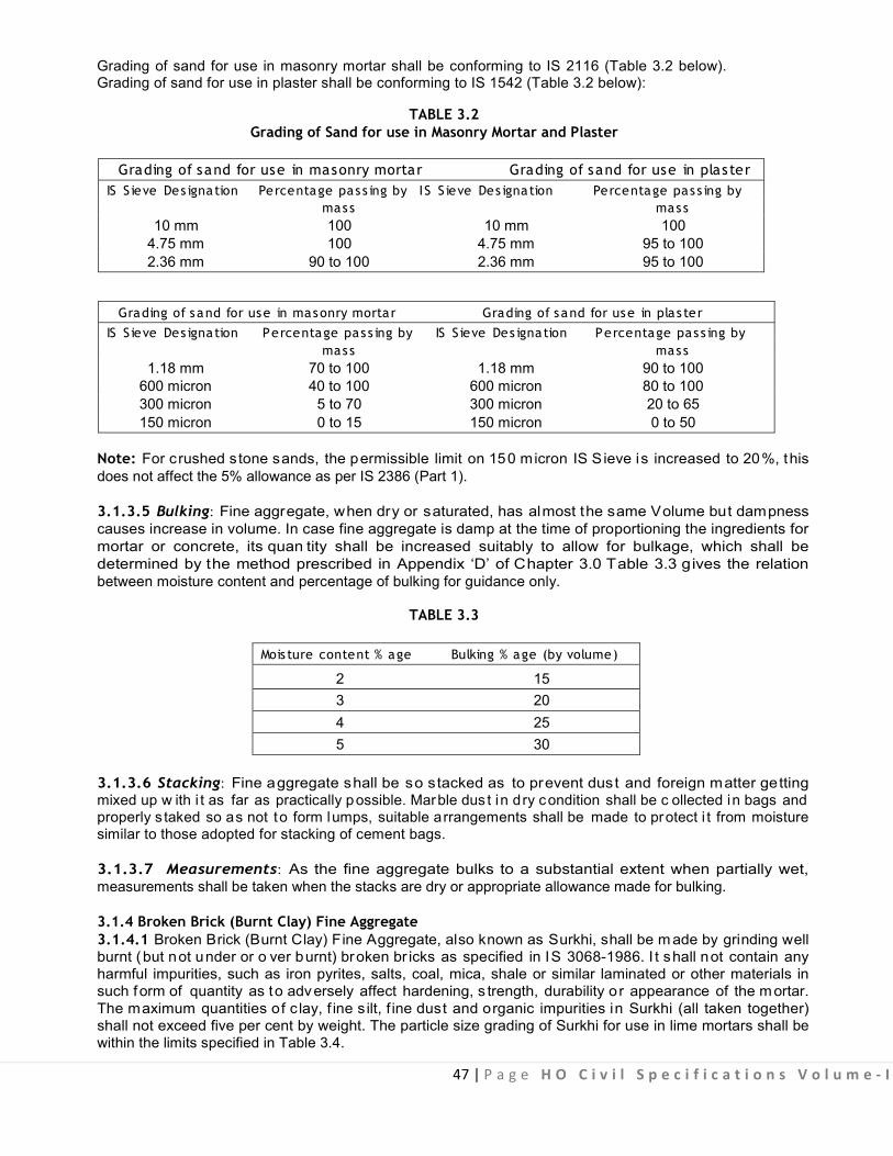
47 | P a g e H O C i v i l S p e c i f i c a t i o n s V o l u m e - I
Grading of sand for use in masonry mortar shall be conforming to IS 2116 (Table 3.2 below). Grading of sand for use in plaster shall be conforming to IS 1542 (Table 3.2 below):
TABLE 3.2 Grading of Sand for use in Masonry Mortar and Plaster
Grading of sand for use in masonry mortar Grading of sand for use in plaster
IS S ieve Des ignation Percentage pas s ing by I S S ieve Des ignation Percentage pas s ing by mass mass
10 mm 100 10 mm 100 4.75 mm 100 4.75 mm 95 to 100 2.36 mm 90 to 100 2.36 mm 95 to 100
Grading of sand for use in masonry mortar Grading of sand for use in plas ter
IS S ieve Des ignation Percentage pas s ing by IS S ieve Des ignation Percentage pas s ing by mass mass
1.18 mm 70 to 100 1.18 mm 90 to 100 600 micron 40 to 100 600 micron 80 to 100 300 micron 5 to 70 300 micron 20 to 65 150 micron 0 to 15 150 micron 0 to 50
Note: For crushed stone sands, the permissible limit on 150 micron IS S ieve is increased to 20%, this does not affect the 5% allowance as per IS 2386 (Part 1).
3.1.3.5 Bulking: Fine aggregate, when dry or saturated, has almost the same Volume but dampness causes increase in volume. In case fine aggregate is damp at the time of proportioning the ingredients for mortar or concrete, its quan tity shall be increased suitably to allow for bulkage, which shall be determined by the method prescribed in Appendix ‘D’ of Chapter 3.0 Table 3.3 gives the relation between moisture content and percentage of bulking for guidance only.
TABLE 3.3 Mois ture content % age Bulking % age (by volume)
2 15 3 20 4 25 5 30
3.1.3.6 Stacking: Fine aggregate shall be so stacked as to prevent dust and foreign matter getting mixed up w ith i t as far as practically possible. Marble dus t in dry condition shall be c ollected in bags and properly s taked so as not to form lumps, suitable arrangements shall be made to protect i t from moisture similar to those adopted for stacking of cement bags. 3.1.3.7 Measurements: As the fine aggregate bulks to a substantial extent when partially wet, measurements shall be taken when the stacks are dry or appropriate allowance made for bulking.
3.1.4 Broken Brick (Burnt Clay) Fine Aggregate 3.1.4.1 Broken Brick (Burnt Clay) Fine Aggregate, also known as Surkhi, shall be m ade by grinding well burnt (but not under or o ver burnt) broken br icks as specified in IS 3068-1986. I t shall not contain any harmful impurities, such as iron pyrites, salts, coal, mica, shale or similar laminated or other materials in such form of quantity as to adversely affect hardening, s trength, durability o r appearance of the mortar. The maximum quantities of c lay, f ine s ilt, f ine dust and organic impurities in Surkhi (all taken together) shall not exceed five per cent by weight. The particle size grading of Surkhi for use in lime mortars shall be within the limits specified in Table 3.4.

48 | P a g e H O C i v i l S p e c i f i c a t i o n s V o l u m e - I
TABLE 3.4 IS S ieve Des ignation Percentage pas s ing (by wt)
4.75 mm 100 2.36 mm 90-100 1.18 mm 70-100 600 microns 40-100 300 microns 5-70 150 microns 0-15
3.1.4.2 Stacking: Surkhi shall be stacked on a hard surface or platform so as to prevent the admixture of clay, dust, vegetation and other foreign matter. It shall be also protected form rain and dampness and kept under adequate coverings.
3.1.4.3 Measurements: Surkhi shall be measured in regular stacks in cubic metres. Alternatively it may be measured by weight when supplied in bags.
3.2 PREPARATION OF MORTARS AND ITS GRADE 3.2.0 Grade of Masonry Mortar
The grade of masonry mortar will be defined by its compressive strength in N/mm2 at the age of 28 days as determined by the standard procedure detailed in IS 2250. 3.2.0.1 For proportioning the ingredients by volume, the conversion of weight into volume shall be made on the following basis:
(a) Burnt Clay Pozzolana 860 Kg/cum (b) Coarse Sand (dry) 1280 kg/cum (c) Fine sand (dry) 1600 kg/ cum (d) Fly Ash 590 kg/ cum
For details of grades and criteria for selection of Masonry mortars see Appendix ‘F’ of chapter-3.
3.2.1 Cement Mortar 3.2.1.1 This shall be prepared by mixing cement and sand with or w ithout the addition of Pozzolana in specified proportions as per Appendix ‘F’.
3.2.1.2 Proportioning: Proportioning on w eight bas is shall be pr eferred taking i nto account specific gravity of sand and moisture content . Boxes of suitable size shall be prepared to facilitate proportioning on weight bas is. C ement ba g w eighting 50 k g s hall be t aken as 0. 035 c ubic m etre. O ther i ngredients i n specified proportion shall be measured using boxes of size 40 x 35 x 25 cm. Sand shall be measured on the basis of its dry volume in the case of volumetric proportioning.
3.2.1.3 Mixing 3.2.1.3.1 The mixing of mortar shall be done i n mechanical mixers operated manually or by power as decided by Engineer-in-Charge. The Engineer-in-Charge may, however, permit hand mixing at his discretion taking into account the nature, magnitude and location of the work and pr acticability of the use of mechanical mixers or where item involving small quantities are to be done or if in his opinion the use of mechanical mixer is not feasible. In cases, where mechanical mixers are not to be used, The contractor shall take permission of the Engineer-in-Charge in writing before the commencement of the work.
49 | P a g e H O C i v i l S p e c i f i c a t i o n s V o l u m e - I
(a) Mechanica l Mixing: Cement and sand in the specified proportions shall be mixed dry thoroughly in a mixer. Water shall then be added gradually and wet mixing continued for at least three minutes. only the required quantity of water shall be added which will produce mortar of workable consistency but not stiff paste. Only the quantity of mortar, which can be used within 30 minutes of its mixing shall be prepared at a time. Mixer shall be cleaned with water each time before suspending the work. (b) Hand Mixing: The measured quantity of sand shall be levelled on a clean masonry platform and cement bags emptied on top. The cement and sand shall be thoroughly mixed dry by being turned over and over, backwards and forwards, several times till the mixture is of a uniform colour. The quantity of dry mix which can be used within 30 minutes shall then be mixed in a masonry trough with just sufficient quantity of water to bring the mortar to a stiff paste of necessary working consistency.
3.2.1.4 Precautions: mortar shall be u sed as soon as possible after mixing and before it begins to set, and in any case within half hour, after the water is added to the dry mixture.

50 | P a g e H O C i v i l S p e c i f i c a t i o n s V o l u m e - I
APPENDIX ‘A’
TEST FOR ORGANIC IMPURITIES (Clause 3.1.3.1)
The aggr egate must al so be checked for or ganic impurities s uch as dec ayed v egetation hum us, coal dust etc.
What is called the colour test is reliable indicator of the presence of harmful organic matter in aggregate, except in the area where there are deposits of lignite.
Fill a 350 ml clear glass medicine bottle upto 70 ml mark with a 3% so lution of caustic soda or sodium hydroxide. The sand is next added gr adually until the volume measured by the sandy layer is 125 ml. The v olume is then made upto 200 ml by addition of more of solution. The bottle is then stoppered and shaken vigorously and allowed to stand for 24 hours. At the end of this period, the colour of the l iquid w ill indicate whether the sand contains a dangerous amount of matter. A colourless l iquid indicates a c lean sand f ree f rom organic m atter. A s traw c oloured solution i ndicates some organic matter but no t enough to be s eriously ob jectionable. D arker c olour means that the s and c ontains injurious amounts and should not be used unless it is washed, and a retest shows that it is satisfactory.
Add 2.5 ml of two per cent solution of tannic acid in 10 per c ent alcohol, to 97.5 ml of three per c ent sodium hydroxide solution. Place in a 350 ml bottle, fix the stopper, shake vigorously and allow to stand for 24 hours before comparison with the solution above the sand. Note: A three per cent solution of caustic soda is made by dissolving 3 g of sodium hydroxide in 100 ml of water, preferably distilled. T he solution should be kept in a glass of bottle tightly closed with a rubber stopper. Handling sodium hydroxide with moist hands may result in serious burns. Care should be taken not to spill the solution for it is highly injurious to clothing, leather, and other materials.
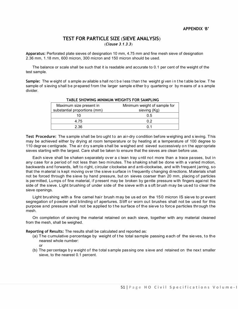
51 | P a g e H O C i v i l S p e c i f i c a t i o n s V o l u m e - I
APPENDIX ‘B’
TEST FOR PARTICLE SIZE (SIEVE ANALYSIS) (Clause 3.1.3.3)
Apparatus: Perforated plate sieves of designation 10 mm, 4.75 mm and fine mesh sieve of designation 2.36 mm, 1.18 mm, 600 micron, 300 micron and 150 micron should be used.
The balance or scale shall be such that it is readable and accurate to 0.1 per cent of the weight of the test sample.
Sample: The w eight of s ample av ailable s hall no t b e l ess t han t he weight gi ven i n t he t able be low. T he sample of s ieving s hall b e prepared f rom the larger sample e ither b y quartering or by m eans of a s ample divider.
TABLE SHOWING MINIMUM WEIGHTS FOR SAMPLING Maximum size present in Minimum weight of sample for
substantial proportions (mm) sieving (Kg) 10 0.5
4.75 0.2 2.36 0.1
Test Procedure: The sample shall be bro ught to an ai r-dry condition before weighing and s ieving. This may be achieved either by drying at room temperature or by heating at a temperature of 100 degree to 110 degr ee c entigrade. The ai r d ry s ample s hall be weighed and sieved successively o n t he appr opriate sieves starting with the largest. Care shall be taken to ensure that the sieves are clean before use.
Each s ieve shall be shaken separately over a c lean tray until no t more than a trace passes, but in any case for a period of not less than two minutes. The shaking shall be done with a varied motion, backwards and forwards, left to right, c ircular c lockwise and anti-clockwise, and w ith f requent jarring, so that the material i s kept moving over the s ieve surface in f requently changing di rections. Materials shall not be forced through the s ieve by hand pressure, but on sieves coarser than 20 mm, placing of particles is permitted, Lumps of fine material, i f present may be broken by gentle pressure with fingers against the side of the sieve. Light brushing of under side of the sieve with a s oft brush may be us ed to clear the sieve openings.
Light brushing with a fine camel hai r brush may be us ed on the 150 micron IS sieve to pr event segregation of powder and blinding of apertures. Stiff or worn out brushes shall not be used for this purpose and pressure shall not be applied to t he surface of the sieve to force particles through the mesh.
On completion of sieving the material retained on each sieve, together with any material cleaned from the mesh, shall be weighed.
Reporting of Results: The results shall be calculated and reported as: (a) The cumulative percentage by weight of t he total sample passing each of the sieves, to the nearest whole number:
or (b) The percentage b y weight o f the total s ample passing one s ieve and retained on the nex t smaller sieve, to the nearest 0.1 percent.

52 | P a g e H O C i v i l S p e c i f i c a t i o n s V o l u m e - I
APPENDIX ‘C’
TEST FOR SILT CONTENT (Clause 3.1.3.2)
The sand shall not contain more than 8% of silt as determined by field test with measuring cylinder. The method of determining silt contents by field test is given below:
A sample of sand to be t ested shall be p laced without drying in a 200 ml measuring cylinder. The volume of the sample shall be such that it fills the cylinder upto 100 ml mark
Clean water shall be added upto 150 ml mark. Dissolve a l ittle salt in the water in the proportion one tea spoon to half a l itre. The mixture shall be shaken v igorously, the last few shakes being s idewise direction to level off the sand and the contents allowed to settle for three hours.
The height of the silt visible as settled layer above the sand shall be expressed as a percentage of the height of sand below. The sand containing more than the above al lowable percentage of silt, shall be washed so as to bring the silt contents within allowable limits.

53 | P a g e H O C i v i l S p e c i f i c a t i o n s V o l u m e - I
APPENDIX ‘D’
BULKING OF FINE AGGREGATES/SAND (FIELD METHODS) (Clause 3.1.3.5)
Two methods are suggested for determining the bulking of sand/fine aggregate. The procedure may be
suitably v aried, i f nec essary. B oth depend on t he f act t hat t he v olume of i nundated s and/fine aggregate is the same if the sand/fine aggregate were dry. Method -1: Put sufficient quantity of sand loosely into a container until it is about two-third full. Level off the top of t he sand and push a s teel rule vertically down through the s and at th e middle to bo ttom, measure the height. Suppose this is ‘X’ cm.
Empty the sand ou t of the container into another container where none of i t is lost. Half fill the first container with water. Put back about half the sand and rod it with a steel rod, about 6 mm in diameter, so that its volume is reduced to a minimum. Then add the remainder and level the top surface of the inundated sand. Measure its depth at the middle with the steel rule. Suppose this is ‘Y’ cm.
The per centage of bul king of t he s and due t o moisture s hall b e c alculated f rom t he f ormula:
Percentage bulking = (X/Y -1) X 100
Method-2: In a 250 ml measuring cylinder, pour the damp sand, consolidate it by staking until it reached the 200 ml mark.
Then fill the cylinder with the water and stir the sand well (the water shall be sufficient to submerge the sand completely). It will be seen that the sand surface is now below its original level. Suppose the surface is at the mark of Yml, the percentage of bulking of sand due to moisture shall be calculated from the formula.
Percentage bulking= (200/Y - 1) x 100

54 | P a g e H O C i v i l S p e c i f i c a t i o n s V o l u m e - I
APPENDIX ‘F’
CRITERIA FOR SELECTION OF MASONRY MORTARS (Clauses 3.2.0, 3.2.0.1, 3.2.1.1)
(a) T he s election of masonry m ortars from dur ability c onsideration will ha ve t o c over bot h t he l oading a nd exposure condition of the masonry. The masonry mortar shall generally be as specified below in (b) to (g). (b) In case of masonry exposed frequent to rain and where there is further protection by way of plastering or rendering or other finishes, the grade of mortar shall not be less than 0.7 MM but shall preferably be of grade MM2. Where no protection is provided, the grade of mortar for external wall shall not be less than MM2. (c) In case of load bearing internal walls, the grade of mortar shall preferably be MM 0.702 or more for high durability but in no case less than MM 0.5. (d) In the case of masonry work in foundations laid below damp proof course, the grade of mortar for use in masonry shall be as specified below.
(i) Where soil has little moisture, masonry mortar of grade not less than MM 0.7 shall be used. (ii) Where soil is very damp, masonry mortar of grade preferably MM 2 or more shall be used. But in no case shall the grade of mortar be less than MM 2.
(e) For masonry in building subject to vibration of machinery, the grade of mortar shall not be less than MM 3. (f) For parapets, where the height is greater than thrice the thickness, the grade of masonry mortar shall not be less than MM3. In case of low parapets the grade of mortar shall be the same as used in the wall masonry. (g) The grade of mortar for bedding joints in masonry with large concrete blocks shall not be less than MM 3. (h) The compressive strength shall be determined in accordance with the procedure given in IS 2250. (i) While mixing the p ozzolanic m aterial l ike f ly ash in mortars Ordinary Portland cement only s hall be use. Grade of Masonry Mortar (IS 2250 )
(Clause 3.2.0)
S l. No. Grade Compress ive s trength at Cement Pozzolana Sand
28 days in N/mm2 (Fly Ash) 1 MM 0.7 0.7 to 1.5 1 --- 8 2 1 0.4* 10 3 MM 1.5 1.5 to 2.0 1 --- 7 4 1 0.4* 8.75 5 MM 3 3.0 to 5.0 1 ---- 6 6 1** 0.21 4.2 7 1 0.4* 7.5 8 MM 5 5.0 to 7.5 1 ---- 5 9 1 0.4 6.25
10 1 0.4 5 11 MM 7.5 7.5 & above 1 ---- 4 12 1** 0.2* 2.1 13 1 --- 3 14 1 0.4 3.75
* Note :Pozzolana of minimum lime reactivity of 4 N/MM2
** This ratio by volume correspondence approximately to cement Pozzolana ratio of 0.8:0.2 by weight. In this case, only ordinary Portland cement is to be used (see IS 269). Specifications for ordinary rapid hardening and low heat Portland Cement (Third revision).
Note : Compressive strength shall be determined in accordance with the Appendix -A-IS 2550.
. .

55 | P a g e H O C i v i l S p e c i f i c a t i o n s V o l u m e - I
4.0: Concrete Work

56 | P a g e H O C i v i l S p e c i f i c a t i o n s V o l u m e - I
CONTENTS
Clause No. Brief Description Page No.
List of Mandatory Tests 57 List of Bureau of Indian Standard Codes 58
4.1 Material 59 4.1.1 Coarse Aggregate 59 4.1.2 Chemical Admixtures 61 4.2 Cement Concrete 62 4.2.1 Grades of Cement Concrete 62 4.2.2 Workability of Concrete 64 4.2.3 Concrete Mix Proportioning 65 4.2.4 Batching 65 4.2.5 Mixing 67 4.2.6 Placing 69 4.2.7 Compaction 69 4.2.8 Construction Joints 69 4.2.9 Concreting under Special Conditions 69 4.2.10 Curing 70 4.2.11 Testing of Concrete 71 4.2.12 Form Work 71 4.2.13 Finishes 71 4.2.14 Durability of Concrete 71 4.2.15 Measurements 74 4.2.16 Rate 76 4.3 Cement Fly Ash Concrete – DELETED 76 4.4 Damp Proof Course 77 4.4.1 Cement Concrete Layer 77 4.4.2 Curing 77 4.4.3 Application of Hot Bitumen 77 4.4.4 Water Proofing Materials 77 4.4.5 Measurements 77 4.4.6 Rate 77 Appendix A Determination of Particle Size 78 Appendix B Test for Surface Moisture 78 Appendix C Determination of Ten Per cent Fine Value 79 Appendix D Slump Test 81
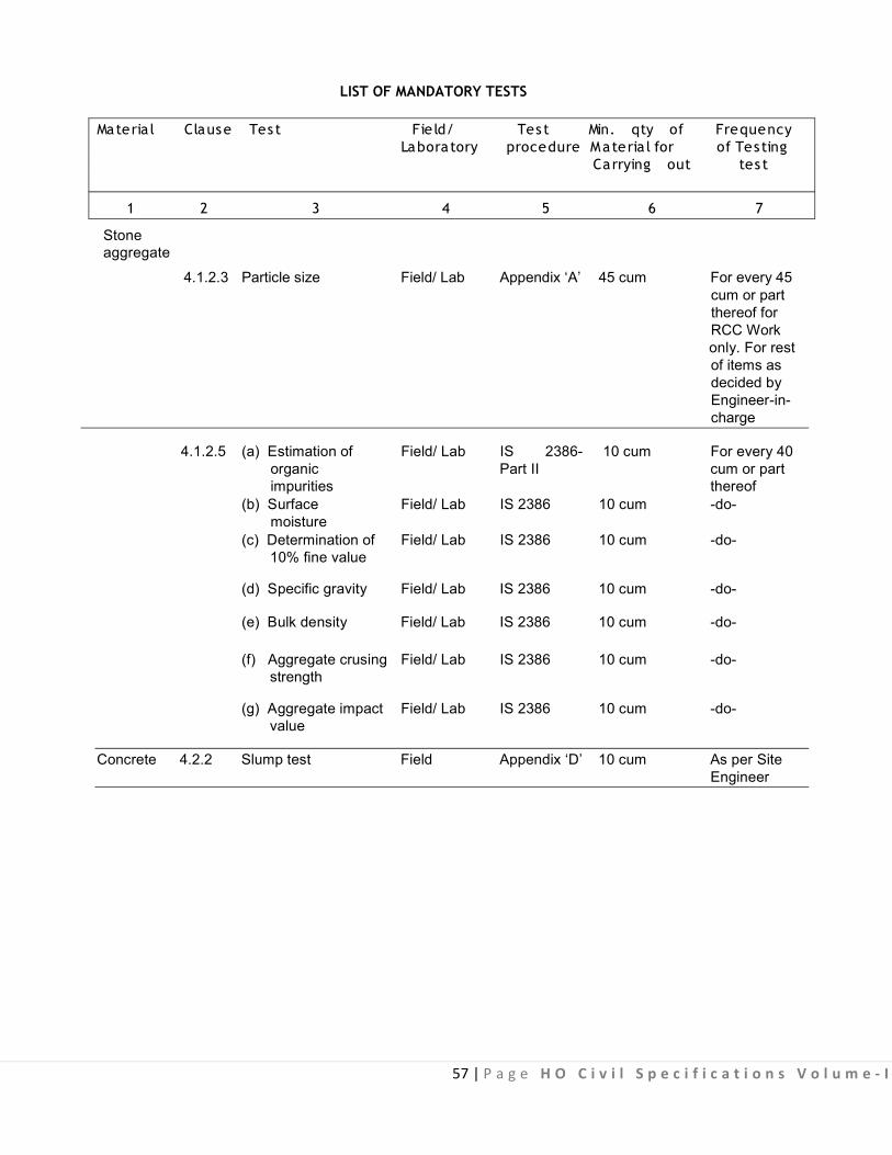
57 | P a g e H O C i v i l S p e c i f i c a t i o n s V o l u m e - I
LIST OF MANDATORY TESTS Materia l Clause Tes t Fie ld/ Tes t Min. qty of Frequency
Laboratory procedure M ateria l for of Testing Carrying out tes t
1 2 3 4 5 6 7
Stone aggregate
4.1.2.3 Particle size Field/ Lab Appendix ‘A’ 45 cum For every 45 cum or part thereof for RCC Work only. For rest of items as decided by Engineer-in- charge
4.1.2.5 (a) Estimation of Field/ Lab IS 2386- 10 cum For every 40 organic Part II cum or part impurities thereof
(b) Surface Field/ Lab IS 2386 10 cum -do- moisture
(c) Determination of Field/ Lab IS 2386 10 cum -do- 10% fine value
(d) Specific gravity Field/ Lab IS 2386 10 cum -do-
(e) Bulk density Field/ Lab IS 2386 10 cum -do-
(f) Aggregate crusing Field/ Lab IS 2386 10 cum -do- strength
(g) Aggregate impact Field/ Lab IS 2386 10 cum -do- value
Concrete 4.2.2 Slump test Field Appendix ‘D’ 10 cum As per Site Engineer

58 | P a g e H O C i v i l S p e c i f i c a t i o n s V o l u m e - I
LIST OF BUREAU OF INDIAN STANDARDS CODES
S. No. I. S . No. Subject
1. IS 383 Specification for coarse and fine aggregate from natural sources for concrete.
2. IS 456 Plain and reinforced concrete - Code of practice
3. IS 516 Method of test for strength of concrete
4. IS 1199 Method of sampling and analysis of concrete
5. IS 1200 Method of measurement of building and civil engineering work (concrete (Part II) work)
6. IS 1322 Specification for bitumen felt for water proofing and damp proofing.
7. IS 1791 General requirements for batch type conrete mixers
8. IS 2386 Method of test for aggregates for concrete
(a) Part I - Particle size and shape
(b) Part II - Estimation of deleterious materials and organic impurities
(c) Part III - Specific gravity, density, voids absorption and bulking.
(d) Part IV - Mechanical properties.
(e) Part V - Soundness
9. IS 2505 General requirements for concrete vibrators - immersion type.
10. IS 2506 General requirements for concrete vibrators - screed board concrete vibrators
11. IS 2645 Specification for integral water proofing compounds for cement mortar and concrete
12. IS 3068 Specification for broken brick (burnt clay) coarse aggregate for use in concrete.
13. IS 3812 Specification for fly ash for use as Pozzolana and admixture in cement mortar and concrete.
14. IS 4656 Specification for form vibrators for concrete.
15. IS 7861 Code of practice for extreme weather concreting (Part-I) recommended (Part-I) practice for hot weather concreting.
16. IS 7861 Code of practice for extreme weather concreting (Part-II) recommended. (Part-II)
17. IS 9103 Specification for concrete admixtures.
59 | P a g e H O C i v i l S p e c i f i c a t i o n s V o l u m e - I
4.0 CONCRETE WORK 4.1. MATERIAL
Water, c ement, fine aggregate or sand and Surkhi, shall be as specified in Chapter 3.0 - Mortar. 4.1.1 Coarse Aggregate
4.1.1.1 General: Aggregate most of which is retained on 4.75 mm IS Sieve and contains only as much fine material as is permitted in IS 383 for various sizes and grading is known as coarse aggregate. Coarse aggregate shall be specified as stone aggregate, gravel or br ick aggregate and it shall be obtained from approved/ authorized sources.
(a) Stone Aggrega te : It shall consist of naturally occurring (uncrushed, crushed or broken) stones. It shall be hard, strong, dense, durable and clean. It shall be free from veins, adherent coating, injurious amounts of disintegrated pieces, alkali, vegetable matter and other deleterious substances. It shall be roughly cubical in shape. Flaky and elongated pieces shall be avoided. It shall conform to IS 383 unless otherwise specified. (b) Grave l: It shall consist of naturally occurring (uncrushed, crushed or broken) river bed shingle or pit gravel. It shall be sound, hard and clean. It shall be free from flat particles of shale or similar laminated material, powdered clay, silt, loam, adherent coating, alkali, vegetable matter and other deleterious substances. Pit gravel shall be washed if it contains soil materials adhering to it. These shall conform to IS 383 unless otherwise specified.
(c) Brick Aggrega te : Brick aggregate shall be obtained by breaking well burnt or over burnt dense brick/ brick bats. They shall be homogeneous in texture, roughly cubical in shape and clean. They shall be free from unburnt clay particles. Soluble salt, silt, adherent coating of soil, vegetable matter and other deleterious substances. Such aggregate should not contain more than one percent of sulphates and should not absorb more than 10% of their own mass of water, when used in cement concrete. It shall conform to IS 3068 unless otherwise specified.
(d) Light weight aggregate such as sintered fly ash aggregate may also be used provided the Engineer-in-Charge is satisfied with the data on the proportion of concrete made with them.
4.1.1.2 Deleterious Material: Coarse aggregate shall not contain any deleterious material, such as pyrites, c oal, l ignite, mica, shale o r s imilar l aminated material, clay, al kali, s oft fragments, sea shells an d organic impurities in such quantity as to affect the strength or durability of the concrete. Coarse aggregate to be used for reinforced cement concrete. Coarse aggregate to be used for reinforced cement concrete shall not contain an y m aterial l iable t o at tack the steel reinforcement. Aggregates which are chemically reactive with alkalies of cement shall not be used. The maximum quant ity of deleterious material shall not be more than five percent of the weight of coarse aggregate when determined in accordance with IS 2386.
4.1.1.3 Size and Grading (i) Stone aggregate and grave l: It shall be ei ther g raded or single s ized as specified. Nominal s ize and grading shall be as under:-
(a) Nominal sizes of graded stone aggregate or gravel shall be 40, 20, 16, or 12.5 mm as specified. For any one of the nominal sizes, the proportion of other sizes as determined by the method prescribed in Appendix ‘A’ of Chapter 4 shall be in accordance with Table 4.1.
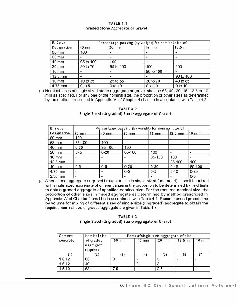
60 | P a g e H O C i v i l S p e c i f i c a t i o n s V o l u m e - I
TABLE 4.1
Graded Stone Aggregate or Gravel IS S ieve Percentage pas s ing (by we ight) for nominal s ize of Des ignation 40 mm 20 mm 16 mm 12.5 mm 80 mm 100 - - - 63 mm - - - - 40 mm 95 to 100 100 - - 20 mm 30 to 70 95 to 100 100 100 16 mm - - 90 to 100 - 12.5 mm - - - 90 to 100 10 mm 10 to 35 25 to 55 30 to 70 40 to 85 4.75 mm 0 to 5 0 to 10 0 to 10 0 to 10
(b) Nominal sizes of single sized stone aggregate or gravel shall be 63, 40, 20, 16, 12.5 or 10 mm as specified. For any one of the nominal size, the proportion of other sizes as determined by the method prescribed in Appendix ‘A’ of Chapter 4 shall be in accordance with Table 4.2.
TABLE 4.2 Single Sized (Ungraded) Stone Aggregate or Gravel
IS S ieve Percentage pas s ing (by we ight) for nominal s ize of Des ignation 63 mm 40 mm 20 mm 16 mm 12.5 mm 10 mm 80 mm 100 - - - - - 63 mm 85-100 100 - - - - 40 mm 0-30 85-100 100 - - - 20 mm 0- 5 0-20 85-100 100 - - 16 mm - - - 85-100 100 - 12.5 mm - - - - 85-100 100 10 mm 0-5 0-5 0-20 0-30 0-45 85-100 4.75 mm - - 0-5 0-5 0-10 0-20 2.36 mm - - - - - 0-5
(c) When stone aggregate or gravel brought to site is single sized (ungraded), it shall be mixed with single sized aggregate of different sizes in the proportion to be determined by field tests to obtain graded aggregate of specified nominal size. For the required nominal size, the proportion of other sizes in mixed aggregate as determined by method prescribed in Appendix ‘A’ of Chapter 4 shall be in accordance with Table 4.1. Recommended proportions by volume for mixing of different sizes of single size (ungraded) aggregate to obtain the required nominal size of graded aggregate are given in Table 4.3.
TABLE 4.3 Single Sized (Ungraded) Stone Aggregate or Gravel
Cement Nomina l s ize Parts of s ingle s ize aggregate of s ize concrete of graded 50 mm 40 mm 20 mm 12.5 mm 10 mm
aggregate required
(1) (2) (3) (4) (5) (6) (7) 1:6:12 63 9 - 3 - - 1:6:12 40 - 9 3 - - 1:5:10 63 7.5 - 2.5 - -
.

61 | P a g e H O C i v i l S p e c i f i c a t i o n s V o l u m e - I
(1) (2) (3) (4) (5) (6) (7) 1:5:10 40 - 7.5 2.5 - - 1:4:8 63 6 - 2 - - 1:4:8 40 - 6 2 - - 1:3:6 63 4.5 - 1.5 - - 1:3:6 40 - 4.5 1.5 - - 1:3:6 20 - - 4.5 - 1.5 1:2:4 40 - 2.5 1 - 1.5 1:2:4 20 - - 3 - 1 1:2:4 12.5 - - - 3 1 1: 11/2 :3 20 0 0 2 - 1
(i) The proportions indicated in Table 4.3 above are by volume when considered necessary, these proportions may be varied marginally by Engineer-in-Charge af ter making sieve analysis of aggregate brought to site for obtaining required graded aggregate. No adjustments in rate shall be made for any variation in the proportions so o rdered by the Engineer-in-Charge. I f single s ize coarse agg regate are no t premixed at site to obtain the graded coarse aggregate required for the m ix, the volume of s ingle s ize aggregates required for the mix shall be s uitably increased to account for reduction in total volume at the site of mixing.
(ii) Brick Aggregate : Nominal size of brick aggregate shall be 40 mm and its grading shall be as specified in Table 4.4 when tested for sieve analysis for the method prescribed in Appendix ‘A’ of Chapter 4.0.
TABLE 4.4 Brick Aggregate
IS S ieve Des ignation Percentage pass ing (by weight)
75 mm 100 37.5 mm 95-100 20.0 mm 45-100 4.75 mm 0.50
4.1.1.4 Stacking: Aggregate shall be s tacked on a ha rd, dry and level patch of ground. When stack piling, the aggregate shall not form pyramids resulting in segregation of different sized materials. It shall be stacked separately ac cording t o no minal s ize o f coarse aggr egates. S tacking s hall be done i n regular stacks, of height not exceeding 100 cm.
4.1.1.5 Testing: Coarse aggregate shall be tested for the followings (as per IS 2386) (a) Determination of particle size and shape (Appendix ‘A’ of Chapter 4) (b) Estimation of organic impurities (as per IS 2386 - Part II) (c) Surface moisture (Appendix ‘B’ of Chapter 4) (d) Determination of 10% fine value (Appendix ‘C’ of Chapter 4)
4.1.1.6 Measurements: The aggregates shall be measured in s tacks and paid for af ter making a deduction o f 7 .5% o f t he gross measurements o f stacks i n respect o f aggregates o f nominal s ize 40 mm and above. No deduction from the gross measurements o f the stacks is to be made in respect o f aggregate of nominal size below 40 mm.
4.1.2 Chemical Admixtures When required, admixtures of a pproved quality shall be m ixed w ith concrete, as specified. The
admixtures shall conform to IS 9103 and as specified in Chapter 5 - R.C.C.

62 | P a g e H O C i v i l S p e c i f i c a t i o n s V o l u m e - I
4.1.2.1 Admixtures may be any one of the following classes for use in concrete:-
(a) Water Reducing Admixtures (b) Retarding Admixtures (c) Accelerating Admixtures. (d) Water Reducing and Retarding Admixtures. (e) Water Reducing and Accelerating Admixtures. (f) Permeability Reducing (water proofing) Admixtures.
4.1.2.2 Liquid Admixtures: Admixtures introduced into the concrete as l iquids generally fall i nto the following categories.
(a) Air Entraining. (b) Water Reducing. (c) Water Reducing Retarders. (d) Retarders. (e) Water Reducing Accelerators. (f) Accelerators.
4.1.2.3 Dosage of these admixtures may vary according to manufacturers specification.
4.1.2.4 Two or more admixtures may not be compatible in the same solution. It is therefore mandatory that when two admixtures manufactured by the same manufacturers is being used simultaneously, the manufacturer shall certify the ir compatibility. In case the two or more admixtures are produces by different manufacturers, then, before their use in concrete, test shall be performed by the manufacturer to establish t heir compatibility, al l s uch t est re ports shall b e f urnished t o t he Engineer-in-Charge for hi s approval before their use in concrete.
4.1.2.5 Some admixture may be in the form of powder, particle or hi gh concentration liquids which may require mixing with water pr ior to dos ing. Under these conditions water in solution shall be considered as part of total water content in the batch in order to maintain the water-cement ratio.
4.1.2.6 Admixture manufacturer’s recommendation shall be c arefully followed so as to ensure complete solution of the product or to prepare a standard solution of uniform strength for easier use. 4.1.2.7 Certain admixtures may c ontain significant amounts o f finely di vided insoluble materials o r ac tive ingredients which may or may not be readily soluble. It is essential for such admixtures that precautions be taken to ensure that these constituents be kept in a state o f un iform s uspension be fore actual batching. When relatively small amounts of powered admixtures are to be u sed di rectly, these shall be pre-blended with cement. 4.1.2.8 Admixtures are sold under various trade names and may be in the form of liquids or powders. The proprietary name and the net quantity of content shall be c learly indicated in each package or container of admixtures. The admixtures shall be uniform within each batch and uniform between all batches. 4.1.2.9 No admixtures shall be accepted for use in concrete unless these are tested in accordance with IS 9103 and the test results are approved by the Engineer-in-Charge. 4.2. CEMENT CONCRETE 4.2.1 Grades of Cement Concrete
The concrete shall be in grade designated as under:
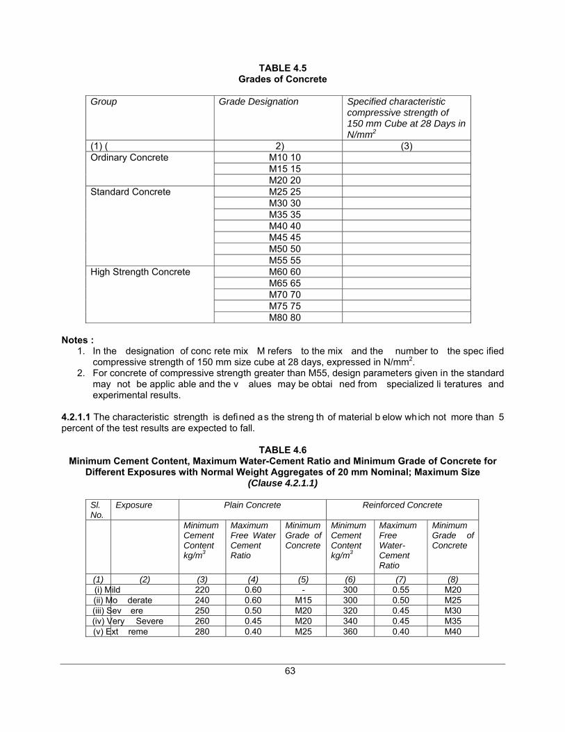
63
TABLE 4.5 Grades of Concrete
Group Grade Designation Specified characteristic
compressive strength of 150 mm Cube at 28 Days in N/mm2
(1) ( 2) (3) M10 10 M15 15
Ordinary Concrete
M20 20 M25 25 M30 30 M35 35 M40 40 M45 45 M50 50
Standard Concrete
M55 55 M60 60 M65 65 M70 70 M75 75
High Strength Concrete
M80 80 Notes :
1. In the designation of conc rete mix M refers to the mix and the number to the spec ified compressive strength of 150 mm size cube at 28 days, expressed in N/mm2.
2. For concrete of compressive strength greater than M55, design parameters given in the standard may not be applic able and the v alues may be obtai ned from specialized li teratures and experimental results.
4.2.1.1 The characteristic strength is defined as the streng th of material b elow which not more than 5 percent of the test results are expected to fall.
TABLE 4.6 Minimum Cement Content, Maximum Water-Cement Ratio and Minimum Grade of Concrete for
Different Exposures with Normal Weight Aggregates of 20 mm Nominal; Maximum Size (Clause 4.2.1.1)
Sl. No.
Exposure Plain Concrete Reinforced Concrete
Minimum Cement Content kg/m3
Maximum Free Water Cement Ratio
Minimum Grade of Concrete
Minimum Cement Content kg/m3
Maximum Free Water- Cement Ratio
Minimum Grade of Concrete
(1) (2) (3) (4) (5) (6) (7) (8) (i) Mild 220 0.60 - 300 0.55 M20 (ii) Mo derate 240 0.60 M15 300 0.50 M25 (iii) Sev ere 250 0.50 M20 320 0.45 M30 (iv) Very Severe 260 0.45 M20 340 0.45 M35 (v) Ext reme 280 0.40 M25 360 0.40 M40

64 | Page HO Civil Specifications Volume - I
Notes: 1. Cement content prescribed in this Table is i rrespective of the grades of c ement. The addi tions
such as fly or ground g ranulated blast furnace slag may be taken into account in the conc rete composition with respe ct to the c ement c ontent and water-cement ratio, if the s uitability is established and as long as the maximum amounts taken into account do not exceed the limit of pozzolona and slag specified in IS 1489 (Part 1) and IS 455 respectively.
2. Minimum grade for plain concrete under mild exposure condition is not specified. 3. The abo ve minimum c ement conte nt and ma ximum water ce ment rat io app ly only to 20 mm
nominal maximum size aggregate. For other sizes of aggregate, these should be changed as per Table 6 of IS 456.
The minimum grade of concrete for plain and reinforced concrete shall be as per Table 4.6. 4.2.1.2 Concrete o f grades lo wer than thos e given in Table 4.6 may be used for l ean conc rete, foundation for masonry walls or temporary reinforced concrete construction. 4.2.2 Workability of Concrete 4.2.2.1 The concrete mix proportion chosen should be such that the concrete is of adequate workability for the placing c onditions of the co ncrete and c an properly be compacted with the means a vailable. Suggested ranges of workability of concrete measured in accordance with IS 1199 are given below:
Placing Conditions
Degree of Workability Slump (mm)
(1) (2) (3) Blinding conc rete: s hallow sections: P avements using pavers
Very low See 4.2.2.2
Mass con crete: Li ghtly reinforced sections in s labs, beams, wall, columns, : floors
Low 25-75
Hand placed pa vements: cana l lining; Strip footing
Heavily re inforced se ctions in slabs, beams, walls, columns:
Medium 50-100
Slip for m work: Pumped concrete
Medium 75-100
Trench fill High 100-150 Tremie concrete Very High See 4.2.2.3
Note:- For mo st o f the p lacing con ditions, internal vibrators (needle vibrators) are s uitable. The
diameter of the needle shall be determined based on the density and spacing of reinforcement bars and thickness of sections. For tremie concrete, vibrators are not required to be used (see also 4.2.7)
4.2.2.2 In the ‘very low’ category of workability where strict control is necessary, for example, pavement quality con crete, measurement of workab ility be determination of c ompacting factor will b e more appropriate than slump ( see IS 1199) and a value of compacting factor of 0.75 to 0.80 is suggested. 4.2.2.3 In the ‘very high’ category of workability, measurement of workability by determination of flow will be appropriate (see IS 9103).

65 | Page HO Civil Specifications Volume - I
4.2.3 Concrete Mix Proportioning 4.2.3.1 The determination of the p roportion of cement, aggregate and water to attain the required strength shall be made as follows:
(a) By designing the concrete mix: such concrete shall be ca lled ‘Design mix concrete’, for detai ls reference may be made to RCC Chapter.
(b) By adopting nominal concrete mix: such concrete shall be called ‘Nominal mix concrete’.
Design mix concrete is preferred to nomina l mi x. If design mix concrete cannot be use d for any reason on the work for grades of M20 or lower, nomi nal mix es ma y be used with the permis sion of Engineer-in-Charge, which, however, is likely to involve a higher cement content. 4.2.3.2 Nominal Mix Concrete: Nominal Mix Concrete may be used for concrete of M20 or lower. The proportions of materials for nominal mix concrete shall be in accordance with Table 4.7. The cement content of t he mix specified in Tab le 4.7 for any nominal mix sha ll be proportionately increased if the quantity of water in the mix has to be increased to overcome the difficulty or placement and compaction, so that the water cement ratio as specified is not exceeded.
TABLE 4.7 Proportions for Nominal Mix Concrete
(Clause 4.2.3.2)
Grade of Concrete Total Quantity of Dry Aggregates by Mass per 50 kg of cement, to be taken as the Sum of the Individual Masses of Fine and Coarse Aggregates, Kg.
Max
Proportion of Fine Aggregate to Coarse Aggregate (by Mass)
Quantity of Water per 50 kg of Cement, max Ltr.
(1) (2) (3) (4) M5 800 60 M7.5 625 45 M10 480 34 M15 330 32 M20 250
Generally 1:2 but subject to an upper limit of 1: 1 ½ and a lower limit of 1:2 ½ 30
Note : - The proportion o f the fine to coa rse aggregate should be adjusted f rom upper limit
progressively as the grading of f ine aggregate bec omes finer and the ma ximum size o f coarse aggregate becomes larger. Graded coarse aggregate shall be used.
Note : - Quantity of water requi red from dur ability point of view may be less than the value given above.
Example For an average grading of fine aggregate (that is, Zone II of Table 4 of IS 383), the proportions shall be 1:1 ½ , 1:2 and 1:2 ½ for maximum size of aggregates 10 mm, 20 mm and 40 mm respectively. 4.2.4 Batching To a void confusi on an d error in batching, consideration shou ld be given to u sing the smalle st practical number of d ifferent concrete mixed on any site or i n any one plant. In batching concrete, the quantity of both cement and aggregate shall be determined by mass; admixture, if solid, by mass: liquid

66 | P a g e H O C i v i l S p e c i f i c a t i o n s V o l u m e - I
admixture may however be m easured in volume or m ass: water shall be w eighed or m easured by volume in a calibrated tank (see also IS 4925). Ready-mixed c oncrete s upplied b y ready-mixed c oncrete pl ant shall be p referred. For l arge and medium project sites the concrete shall be sourced from ready-mixed concrete plants or f rom on s ite or of f s ite batching and mixing plants (see IS 4926). 4.2.4.1 Except where it can be shown to the satisfaction of the Engineer-in-Charge that supply of properly graded aggregate of uniform quality can be m aintained over a period of work, the grading aggregate s hould be controlled b y obtaining the coarse aggregate i n di fferent s izes and bl ending them in the right proportions when required, the different sizes being stocked in separate stock-piles. The material should be stock-piled for several hours preferably a d ay before use. The grading of coarse and fine aggregate should be checked as frequently as possible, the frequency for a given job being determined by the Engineer-in-Charge to ensure that the specified grading is maintained.
4.2.4.2 The accuracy of the measuring equipment shall be within + 2 percent of the quantity of cement being measured and within + 3 percent of the quantity of aggregate, admixtures and water being measured.
4.2.4.3 Proportion/Type and grading of aggregates shall be made by trial in such a w ay so as to obtain densest possible concrete. All ingredients of the concrete should be used by mass only. 4.2.4.4 Volume batching may be al lowed only where weigh-batching is not practicable and provided accurate used in concrete have earlier been established. Allowance for bilking shall be made in accordance with IS 2386 ( Part 3) . The mass volume relationship should be c hecked as f requently as necessary, the frequency for the given job being determined by Engineer-in-Charge to ensure that the specified grading is maintained. 4.2.4.5 It is important to maintain the water cement ratio constant at its correct value. To this end, determination of moisture contents in both fine and coarse aggregates shall be made as frequently as possible, the frequency f or a given j ob be ing det ermined by the E ngineer-in-Charge a ccording t o weather conditions. The amount of t he added water shall be adjusted to compensate for any observed variations in the m oisture contents. For t he determination of m oisture c ontent in t he aggregates, IS 2386 (Part 3) may be referred to. To al low for the variation in mass for aggregate due to variations in their moisture c ontent, suitable adj ustments in t he m asses of aggregates s hall be made. In t he absence of exact data, only in the case of nominal mixes, the amount o f surface water may be estimated from the values given in Table 4.8.
TABLE 4.8 Surface Water Carried by Aggregate
(Clause 4.2.4.5)
S l No. Aggregate Approximate Quantity of Surface Water
Percent by l/m3
mass (1) (2) (3) (4) (i) Very wet sand 7.5 120 (ii) Moderately wet sand 5.0 80 (iii) Moist sand 2.5 40 (iv) 1) Moist gravel or crushed 1.25-2.5 20-40
rock 1) Coarser the aggregate, less the water it will carry.
.

67 | P a g e H O C i v i l S p e c i f i c a t i o n s V o l u m e - I
4.2.4.6 No substitutions in materials used on the work or alteration in the es tablished proportions, except as permitted in 4.2.4.4 and 4. 2.4.5 shall be m ade without additional tests to show that the qual ity and strength of concrete are satisfactory.
4.2.5 Mixing Concrete shall be m ixed in m echanical batch type concrete mixers conforming to IS 1791 having two
blades and fitt ed w ith power l oader (li fting hopper type ). Half bag mixers and mixers without lifti ng hoppers shall not be used for mixing concrete. In exceptional c ircumstances, such as mechanical break down of mixer, work in remote areas or power breakdown and when the quantity of concrete work is very small, hand mixing may be done with the specific p rior permission of the Engineer-in-Charge in writing subject to adding 10% extra cement. When hand mixing is permitted, it shall be carried out on a water tight platform and care shall be taken to ensure that mixing is continued until the concrete is uniform in colour and consistency. Before mixing the brick aggregate shall be well soaked with water for a minimum period of two hours and stone aggregate or gravel shall be washed with water to remove, dirt, dust and ot her f oreign materials. For guidance, t he m ixing t ime m ay be 11/2 to 2 m inutes, f or hydrophobic cement it may be taken as 21/2 to 3 minutes. 4.2.5.1 Power Loader: Mixer will be fitted with a power loader complying with the following requirements.
(a) The hopper shall be of adequate capacity to receive and discharge the maximum nominal batch of unmixed materials without spillage under normal operating conditions on a level site.
Note: In such a case the volume of the maximum nominal batch of mixed material is 50% greater than the nominal mixed batch capacity.
(b) The minimum inside width of the feeding edge of the hopper shall be as specified below in Table 4.9.
TABLE 4.9 Nomina l s ize of mixer (T, NT or R). Minimum ins ide width of hopper feeding edge
litre 140 1.0 200 1.1 280 1.2 375 1.4 500 1.5
1000 2.0 T = Tilting; NT = Non-tilting; R = Reverse
(c) The design of the loader shall be such that it allows the loading hopper to be elevated to such a height that the centre line of the chute plate of the hopper when in discharge position, is at an angle of not less than 50º to the horizontal. A mechanical device to aid discharge of the contents as quickly as possible from the hopper to the drum may also be provided. Even when a mechanical device is provided, it is recommended that the angle of centre line of the chute plate of the hopper when in discharge position, should be as larger as practicable, preferably not less than 40º to horizontal. (d) When the means of raising and lowering the loading hopper includes flexible wire ropes winding on to a drum or drums, the method of fastening the wire to rope to the drums shall be such as to avoid, as far as possible any tendency to cut the strands of the ropes and the fastening should preferably be positioned clear of the barrel of the drum for example, outside the drums flange. When the loading hopper is lowered to its normal loading position, these should be at least one and a half drums of rope on the drum.
.


69 | P a g e H O C i v i l S p e c i f i c a t i o n s V o l u m e - I
During hot or c old weather, c oncrete shall be t ransported in deep c ontainers, ot her s uitable m ethods to reduce the loss of water by evaporation in hot weather and heat loss in cold weather may also be adopted. 4.2.6 Placing
The concrete shall be deposited as nearly as p racticable in its f inal position to avoid rehandling. It shall be laid gently (not thrown) and shall be thoroughly vibrated and compacted before setting commences and should not be s ubsequently disturbed. Method of p lacing shall be such as to preclude segregation. Care shall be taken to avoid displacement of reinforcement or movement of form work and damage due t o rains. As a gener al guidance, the maximum free fall of concrete may be t aken as 1.5 metre. 4.2.7 Compaction
Concrete s hall be tho roughly c ompacted and ful ly w orked a round em bedded fixtures and into corners of the form work. Compaction shall be done by mechanical v ibrator of appropriate type t ill a dense concrete is obtained. The m echanical vibrators shall c onform to IS 250 5, IS 2506, IS 2514 and IS 4656. To prevent segregation, over vibration shall be avoided.
Compaction s hall b e c ompleted be fore the initial setting s tarts. F or the items w here m echanical vibrators are not to be u sed, the contractor shall take permission of the Engineer-in-Charge in writing before the start of the work. After compaction the top surface shall be f inished even and smooth with wooden trowel before the concrete begins to set.
4.2.8 Construction Joints Concreting shall be carried out continuously upto construction joints. The position and arrangement of
construction j oints shall be a s s hown i n t he structural d rawings o r a s di rected b y t he E ngineer-in- Charge. Number of su ch joints shall be kept minimum. Joints shall be kept as st raight as p ossible. Construction joints should comply with IS 11817.
4.2.8.1 When the work has to be resumed on a surface which has hardened, such surface shall be roughened. It shall then be swept clean and thoroughly wetted. For vertical joints, neat cement slurry, of workable consistency by using 2 kgs of cement per sqm shall be applied on the surface before it is dry. For horizontal joints, the surface shall be covered with a layer of mortar about 10-15 mm thick composed of cement and sand in the same ratio as the cement and sand in concrete mix. This layer of cement slurry of mortar shall be freshly mixed and applied immediately before placing of the concrete.
4.2.8.2 Where the concrete has not fully hardened, all laitance shall be removed by scrubbing the wet surface with wire or br istle brushes, care being taken to avoid dislodgement of particles of coarse aggregate. The surface shall be thoroughly wetted and all free water removed. The surface shall then be coated with neat cement s lurry @ 2 kgs of cement per sqm. On this surface, a l ayer of concrete not exceeding 150 mm in thickness shall first be pl aced and shall be well rammed against old work particular at tention be ing paid to corners and c lose spots; work, thereafter, shall proceed in the normal way.
4.2.9 Concreting under Special Conditions 4.2.9.1 Work in Extreme Weather Conditions: During hot and cold weather, the concreting shall be done as per the procedure set out in IS 7861 (Part-I)-1975 and IS 7861 (Part I I)-1981 respectively. Concreting shall not be done when t he t emperature falls below 4.5ºC. In cold weather, the concrete placed shall be protected against frost. During hot weather, it shall be ensured that the temperature of wet concrete does not exceed 38ºC.

70 | P a g e H O C i v i l S p e c i f i c a t i o n s V o l u m e - I
4.2.9.2 Under Water Concreting: Concrete s hall not be dep osited und er water i f i t i s p racticable to dewater the area and place concrete in the regular manner. When it is necessary to deposit concrete under water, the methods, equipment, materials and proportions of the m ix to be used shall be submitted to and approved by the Engineer-in-Charge before the work is started.
Under-water concrete should have a s lump recommended in 4.2.2. The water-cement ratio shall not exceed 0.6 and may need to be s maller, depending on t he grade of concrete or the type of chemical attack. For aggregates of 40 mm maximum particle size, the cement content shall be atleast 350 kg/m3
of concrete.
4.2.9.3 Concrete in Sea Water: Concrete in sea-water or exposed directly along the sea-coast shall be at least M20 Grade in the case of plain concrete and M30 in case of reinforced concrete. The use of slag or Pozzolana cement is advantageous under such conditions.
(i) Special attention shall be given to the design of the mix to obtain the densest possible concrete: slag, broken brick, soft lime stone, soft sandstone, or other porous or weak aggregates shall not be used. (ii) As far as possible, preference shall be given to precast members unreinforced, well-cured and hardened, without sharp corners, and having trowel-smooth finished surfaces free from crazing, cracks or other defect; plastering should be avoided.
(iii) No construction joints shall be allowed within 600 mm below low water-level or within 60 mm of the upper and lower planes of wave action. Where unusually severe conditions or abrasion are anticipated, such parts of the work shall be protected by bituminous or silico-fluoride coatings or stone facing bedded with bitumen.
(iv) In reinforced concrete structures, care shall be taken to protect the reinforcement from exposure to saline atmosphere during storage, fabrication and use. It may be achieved by treating the surface of reinforcement with cement wash or by suitable methods.
4.2.10 Curing
Curing is the process of preventing loss of moisture from the concrete. The following methods shall be employed for effecting curing.
4.2.10.1 Moist Curing : Exposed surfaces of concrete shall be k ept continuously in a damp or wet condition by ponding or by covering w ith a layer of sacking, canvas, Hessian or s imilar materials and kept constantly wet for at least 7 d ays f rom the date of placing concrete in case of ordinary Portland cement and at l east 10 days where mineral admixtures or blended cements a re used. The period o f curing shall not be less than 10 days for concrete exposed to dry and hot weather conditions. In the case of concrete w here m ineral ad mixtures or b lended c ements ar e u sed, it is r ecommended that abo ve minimum periods may be extended to 14 days.
4.2.10.2 Membrane Curing : Approved curing compounds may be used in l ieu of moist curing with the permission of the Engineer-in-Charge. Such compound shall be applied to al l exposed surfaces of t he concrete as soon as possible after the concrete has set. Impermeable membrane such as polythene sheet covering the concrete surface may also be u sed to provide effective barrier against the evaporation.
4.2.10.3 Freshly laid concrete shall be protected from rain by suitable covering.

71 | P a g e H O C i v i l S p e c i f i c a t i o n s V o l u m e - I
4.2.10.4 Over the foundation concrete, the masonry work may be started after 48 hours of its compaction but the curing of exposed surfaces of cement concrete shall be continued along with the masonry work for at eas t 7 day s. And where cement concrete i s used as base concrete for f looring, t he flooring may be commenced before the curing period of base concrete is over but the curing of base concrete shall be continued along with top layer of flooring for a minimum period of 7 days.
4.2.11 Testing of Concrete Testing of concrete shall be done as described in chapter of R.C.C.
4.2.12 Form Work Form work shall be as specified in R.C.C. chapter and shall be paid for separately unless otherwise
specified.
4.2.13 Finishes Plastering and special f inishes o ther than those, obtained through form work shall be specified and
paid for separately unless otherwise specified.
4.2.14 Durability of Concrete A durable concrete is one that performs satisfactorily in the working environment during i ts
anticipated exposure conditions during s ervice. T he m aterials and mix proportions s hall be such a s t o maintain its intergrity and, if applicable, to protect reinforcement from corrosion.
The factors influencing durability include: (a) The environment; (b) The cover to embedded steel; (c) The type and quality of constituent materials; (d) The cement content and water/ cement ratio of the concrete; (e) Workmanship, to obtain full compaction and efficient curing; and (f) The shape and size of the member.
4.2.14.1 Requirements for Durability
4.2.14.1.1 Genera l Environment : The general environment to which the concrete will be exposed during its working life is classified into f ive levels of severity, that is, mild, moderate, severe, very severe and extreme as described in Table 4.9.
TABLE 4.9 Environmental Exposure Conditions
S l. No Environment Exposure Conditions (1) (2) (3) (i) Mild Concrete surfaces protected against weather or aggressive conditions,
except those situated in coastal area. (ii) Moderate Concrete surfaces sheltered from severe rain or freezing whilst wet
Concrete exposed to condensation and rain Concrete continuously under water Concrete i n c ontact or b uried un der no n-aggressive s oil/ gr ound water Concrete surfaces sheltered from saturated salt air in coastal area
(iii) Severe Concrete surfaces exposed to severe rain, alternate wetting and drying or occasional freezing whilst wet or severe condensation. Concrete completely immersed in sea water. Concrete exposed to coastal environment.

72 | P a g e H O C i v i l S p e c i f i c a t i o n s V o l u m e - I
(1) (2) (3) (iv) Very severe Concrete surface exposed to sea water spray, corrosive fumes or
severe freezing conditions whilst wet. Concrete i n c ontact w ith or bur ied unde r aggr essive s ub-soil/ gr ound water.
(v) Extreme Surface of members in tidal zone. Members in direct contact with liquid/ solid aggressive chemicals.
Note: For the purpose of determining exposure conditions, all places within a distance of 10 kms. of coastal line, sea front would be treated as coastal area.
4.2.14.1.2 Fre e zing a nd Tha wing : Where freezing and thawing actions under wet conditions exist, enhanced du rability can be obt ained by the use o f suitable ai r ent raining admixtures. When concrete lower than grade M50 is used under these conditions, the mean total ai r content by volume of the fresh concrete at the time of delivery into the construction should be:
Nominal Maximum Size Aggregate (mm) Entra ined Air Percentage 20 5 + 1 40 4 + 1
4.2.14.1.3 Exposure to S ulpha te Attack : For the very high sulphate concentration in Class 5 c onditions given in Table 4.11, some form of lining such as polyethylene or polychloroprene sheet: or surface coating based on a sphalt, chlorinated rub ber, epo xy; or pol yurethane materials should also be us ed t o prevent access by the sulphate solution. 4.2.14.1.4 Chlorides in Concre te : The total amount of chlorides content (as CI) in the concrete at the time of placing shall be as under :
SI. No. Type of Use of Concrete
(1) (2) (i) Concrete containing metal and steam cured at
elevated t emperature an d pr e-stressed c oncrete (ii) Reinforced concrete or plain concrete containing
embedded metal (iii) Concrete not containing embedded metal or any
material requiring protection from chloride
Maximum T ota l Acid Soluble Chloride
Content expres sed as kg/ m3 of Concrete
(3) 0.4
0.6
3.0
4.2.14.1.5 Sulphates in Concrete : The total water-soluble sulphate content of the concrete mix, expressed as SO3 should not exceed 4 per cent by mass of the cement in the mix. The sulphate content should be calculated as the total from the various constituents of the mix. The 4 per cent limit does not apply to concrete made with super sulphate cement complying with IS 6909.

73 | P a g e H O C i v i l S p e c i f i c a t i o n s V o l u m e - I
TABLE 4.11
Requirements for Concrete Exposed to Sulphate Attack (Clause 4.2.14.1.3)
Sl No. Class
Total S O3 (%)
(1) (2) (3) (i) 1 Traces
(<0.2) (ii) 2 0.2 to 0.5
(iii) 3 0.5 to 1.0
(iv) 4 1.0 to 2.0 (v) 5 More than
2.0
Concentration of s ulphates, Expresed as SO3 Concrete.
In Soil
SO3 in 2:1 ( Wate r: Soil Extract) ( g /l)
(4) Less than 1.0
1.0 to 1.9
1.9 to 3.1
3.1 to 5.0
More than
5.0
In Ground Type of Ce ment Water (g/l)
(5) (6) Less than Ordinary Portland cement 0.3 or Portland slag
cement or Portland - Pozzolana cement
0.3 to 1.2 Ordinary Portland cement or Portland slag cement or Portland Pozzolana cement Super sulphated cement or sulphate resisting Portland cement
1.2 to 2.5 Super sulphated cement or sulphate resisting Portland cement Portland Pozzolana cement or Portland slag cement
2.5 to 5.0 Super sulphated or sulphate r esisting Portland cement
More than Sulphate resisting 5.0 Portland cement or
super sulphated cement with protective c oatings
Dense, Fully compacted made with 20 mm nomina l maximum size Aggregates complying with IS 383 Minimum Maximum Cement Free Content Water- kg/m3 Cement
Ratio (7) (8) 280 0.55
330 0.50
310 0.50
330 0.50
350 0.45
370 0.45
400 0.40
Notes 1. Cement content given in this Table is irrespective of grades of cement.
2. Use of super sulphated cement is generally restricted where the prevailing temperature is above 40°C. 3. Super sulphated cement gives an a cceptable l ife provided that the concrete is dense and prepared with a water-cement ratio of 0.4 or less, in mineral acids, down to pH 3.5. 4. The cement contents given in col. 7 of this Table are the minimum recommended. For SO3
contents near the upper limit of any class, cement contents above these minimum are advised. 5. For severe conditions, such as thin sections under hydrostatic pressure on one side only and sections partly immersed, considerations should be given to a further reduction of water-cement ratio. 6. P ortland slag cement conforming to IS 455 with slag content more than 50 per cent exhibits better sulphate resisting properties.
.

74 | P a g e H O C i v i l S p e c i f i c a t i o n s V o l u m e - I
7. Where chloride is encountered along with sulphates in soil or ground water, ordinary Portland cement with C3A content from 5 to 8 per cent shall be desirable to be used in concrete, instead of sulphate resisting cement. Alternatively, Portland slag cement conforming to IS 455 having more than 50 per cent slag or a blend of ordinary Portland cement and slag may be used provided sufficient information is available on performance of such blended cements in these conditions.
4.2.15 Measurements 4.2.15.1 Dimensions of length, breadth and thickness shall be measured correct to nearest cm. except for the thickness of s lab and partition which shall be measured to nearest 5 mm. Areas shall be worked out to nearest 0.01 sq.m and the cubic contents of consolidated concrete shall be worked out to nearest 0.01 cum. Any work done in excess over the specified dimension or sections shown in the drawing shall be ignored.
4.2.15.2 Concrete work executed in the following conditions shall be measured separately: (a) Work in or under water (b) Work in liquid mud (c) Work in or under foul positions
4.2.15.3 Cast-in-situ concrete and or precast concrete work shall be measured in s tages described in the item of work, such as:
(a) At or near the ground level (b) Upto specified floor level (c) Between two specified floor levels (d) Upto specified height above or depth below plinth level/ defined datum level. (e) Between tow specified heights or depths with reference to plinth/defined datum level.
4.2.15.4 No deduction shall be made for the following: (a) E nds of dissimilar materials for example beams, posts, girders, raf ters, purl ins, t russes, corbels and steps upto 500 sq cm in cross sections. (b) Opening upto 0.1 sq metre (1000 sq.cm) (c) Volume occupied by pipes, conduits, sheathing etc . not exceeding 100 sq c m each in c ross sectional areas. (d) Small voids such as shaded portions in Figure A to J below when these do not exceed 40 s q cm each in cross section.
Note: In calculating area of opening, the thickness of any separate lintel or sill shall be included in the height. Nothing extra shall be payable for forming such openings or voids.
Area of Fig. A to G shall be = L x B
Area of Fig. H & J shall be = L x {Average of B and B’}

75 | Page HO Civil Specifications Volume - I
L
B
A
L
B
B
L
B
C
L
B
D
L
B
E
L
B
F
B
G
B'
H
B'
J
L L L
B B
4.2.15.5 Cast-in-situ and precast concrete work shall be measured sperately. 4.2.15.6 Cast-in-situ concrete shall be classified and measured as follows:
(a) Foundation, footings, bases for columns (b) Walls (any thickness) including attached pilasters, buttresses, plinth and s tring courses, f illets
etc. (c) Shelves (d) Slabs (e) Chajjas including portions bearing on the wall (f) Lintels, beams and bressummers (g) Columns, piers abutments, pillars, post and struts (h) Stair case including stringer beams but excluding landings. (i) Balustrades, newels and sailing (j) Spiral staircase (including landings) (k) Arches (I) Domes, vaults (m) Shell roof, arch ribs and folded piates (n) Chimneys and shaft. (o) Breast walls, retaining, walls, return walls (p) Concrete filling to precast components (q) Kerbs, steps and the like (r) String or la cing courses, parapets , copings, bed block, anchor blocks, plain w indow sills and
the like (s) Cornices and moulded windows sills. (t) Louvers, fins, facia.
4.2.15.7 P recast ceme nt concrete solid article shall be measured separately and shall incl ude use of moulds, f inishing the to p surfaces e ven and smooth with wooden trowel, before setting in p osition in

76 | P a g e H O C i v i l S p e c i f i c a t i o n s V o l u m e - I
cement mortar 1:2 (1 cement : 2 coarse sand). Plain and moulded work shall be measured separately and the work shall be classified and measured as under:
Class ifications (a) Wall panels (b) String or lacing courses,
coping,bed plates, pl ain windows sills, shelves, louvers, steps etc.
(c) Kerbs, edgings etc. (d) Solid block work (e) Hollow block work (f) Light weight partitions
Method of measurement In square meters stating the thickness. In cubic meters.
In cubic meters. In square metres stating the thickness or in cubic meters. In square metres stating the thickness or in cubic metres. In square metres s tating t he partition’s thickness.
4.2.16 Rate The rate is inc lusive of t he cost o f labour and materials involved in all t he operations described
above.
4.3 CEMENT- FLY ASH CONCRETE DELETED
77 | P a g e H O C i v i l S p e c i f i c a t i o n s V o l u m e - I
4.4 DAMP PROOF COURSE 4.4.1 Cement Concrete Layer
This shall consist of cement concrete of specified proportions and thickness. The surface of brick or stone m asonry w ork s hall be levelled an d prepared be fore l aying the cement c oncrete. Edge of damp proof course s hall be s traight, even and v ertical. S ide s huttering s hall c onsist o f s teel forms and shall be strong and properly f ixed so that i t does not get disturbed during compaction and the mortar does not leak through. The concrete mix shall be of workable consistency and shall be tamped thoroughly to make a dens e m ass. W hen t he s ides are removed, t he s urface s hould c ome out s mooth w ithout honeycombing. C ontinuity s hall be m aintained w hile laying the c ement concrete layer and laying shall be terminated only at the predetermined location where damp proof course is to be discontinued. There shall be no construction joints in the Damp Proof Course.
4.4.2 Curing Damp proof course shall be cured for at least seven days, after which it shall be allowed to dry.
4.4.3 Application of Hot Bitumen Where so di rected, hot bi tumen in specified quant ity shall be appl ied over the dr ied up surface of
cement concrete, properly c leaned with brushes and f inally with a pi ece of c loth soaked in kerosene oi l. Bitumen of penetration A 90 or equ ivalent where used shall be heated to a temperature o f 160º ± 5ºC. The hot bitumen shall be applied uniformly all over, so that no blank spaces are left anywhere. It will be paid for separately.
4.4.4 Water Proofing Materials Where so specified, water p roofing material of approved quality shall be added to the concrete
mixture i n ac cordance w ith the m anufacturer’s s pecification s tating the quan tity o f w ater p roofing material in litres or kg per 50 kg or cement and will be paid for separately.
4.4.5 Measurements The length and b readth shall be m easured correct to a c m and i ts area s hall be c alculated in square
metres correct to two places of decimal. The depth shall not be less than the specified thickness at any section.
4.4.6 Rate The rate is in clusive of t he cost o f materials and labour involved in a ll the operations described
above ex cept for the appl ications o f a coat o f ho t bi tumen and addi tion o f water p roofing materials which shall be paid for separately, unless otherwise specified.
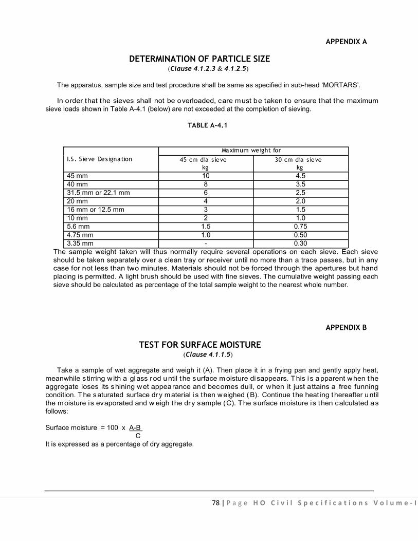
78 | P a g e H O C i v i l S p e c i f i c a t i o n s V o l u m e - I
APPENDIX A
DETERMINATION OF PARTICLE SIZE (Clause 4.1.2.3 & 4.1.2.5)
The apparatus, sample size and test procedure shall be same as specified in sub-head ‘MORTARS’.
In order that the sieves shall not be overloaded, care must be taken to ensure that the maximum sieve loads shown in Table A-4.1 (below) are not exceeded at the completion of sieving.
TABLE A-4.1 Maximum weight for
I.S . S ieve Des ignation 45 cm dia s ieve 30 cm dia s ieve kg kg
45 mm 10 4.5 40 mm 8 3.5 31.5 mm or 22.1 mm 6 2.5 20 mm 4 2.0 16 mm or 12.5 mm 3 1.5 10 mm 2 1.0 5.6 mm 1.5 0.75 4.75 mm 1.0 0.50 3.35 mm - 0.30
The sample weight taken will thus normally require several operations on each sieve. Each sieve should be taken separately over a clean tray or receiver until no more than a trace passes, but in any case for not less than two minutes. Materials should not be forced through the apertures but hand placing is permitted. A light brush should be used with fine sieves. The cumulative weight passing each sieve should be calculated as percentage of the total sample weight to the nearest whole number.
APPENDIX B
TEST FOR SURFACE MOISTURE (Clause 4.1.1.5)
Take a sample of wet aggregate and weigh it (A). Then place it in a frying pan and gently apply heat, meanwhile s tirring w ith a glass rod until t he surface m oisture disappears. This i s apparent when the aggregate loses its shining wet appearance and becomes dull, or when it just attains a free funning condition. The saturated surface dr y material i s t hen weighed ( B). Continue the heat ing thereafter u ntil the moisture is evaporated and w eigh the dry sample (C). The surface moisture is then calculated as follows:
Surface moisture = 100 x A-B C It is expressed as a percentage of dry aggregate.
.
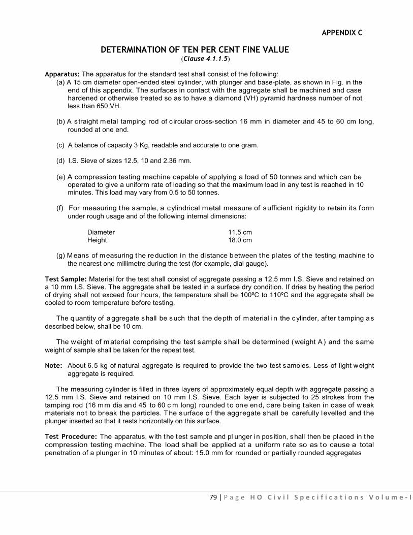
79 | P a g e H O C i v i l S p e c i f i c a t i o n s V o l u m e - I
APPENDIX C
DETERMINATION OF TEN PER CENT FINE VALUE (Clause 4.1.1.5)
Apparatus: The apparatus for the standard test shall consist of the following: (a) A 15 cm diameter open-ended steel cylinder, with plunger and base-plate, as shown in Fig. in the end of this appendix. The surfaces in contact with the aggregate shall be machined and case hardened or otherwise treated so as to have a diamond (VH) pyramid hardness number of not less than 650 VH.
(b) A straight metal tamping rod of c ircular cross-section 16 mm in diameter and 45 to 60 cm long, rounded at one end.
(c) A balance of capacity 3 Kg, readable and accurate to one gram.
(d) I.S. Sieve of sizes 12.5, 10 and 2.36 mm. (e) A compression testing machine capable of applying a load of 50 tonnes and which can be operated to give a uniform rate of loading so that the maximum load in any test is reached in 10 minutes. This load may vary from 0.5 to 50 tonnes.
(f) For measuring the sample, a cylindrical metal measure of sufficient rigidity to retain its form under rough usage and of the following internal dimensions:
Diameter 11.5 cm Height 18.0 cm
(g) Means of measuring the reduction in the distance between the plates of the testing machine to the nearest one millimetre during the test (for example, dial gauge).
Test Sample: Material for the test shall consist of aggregate passing a 12.5 mm I.S. Sieve and retained on a 10 mm I.S. Sieve. The aggregate shall be tested in a surface dry condition. If dries by heating the period of drying shall not exceed four hours, the temperature shall be 100ºC to 110ºC and the aggregate shall be cooled to room temperature before testing.
The quantity of aggregate shall be such that the depth of material i n the cylinder, af ter tamping as described below, shall be 10 cm.
The weight of material comprising the test sample shall be determined (weight A ) and the same weight of sample shall be taken for the repeat test.
Note: About 6.5 kg of natural aggregate is required to provide the two test samoles. Less of light weight aggregate is required.
The measuring cylinder is filled in three layers of approximately equal depth with aggregate passing a 12.5 mm I.S. Sieve and retained on 10 mm I.S. Sieve. Each layer is subjected to 25 strokes from the tamping rod (16 mm dia and 45 to 60 c m long) rounded to one end, care being taken in case of weak materials not to break the particles. The surface of the aggregate shall be carefully levelled and the plunger inserted so that it rests horizontally on this surface.
Test Procedure: The apparatus, with the test sample and pl unger in pos ition, shall then be placed in the compression testing machine. The load shall be applied at a uniform rate so as to cause a total penetration of a plunger in 10 minutes of about: 15.0 mm for rounded or partially rounded aggregates

80 | Page HO Civil Specifications Volume - I
(for ex ample uncrushed gravel) 20 mm for nomina l crushed aggreg ate & 24 mm for honey co mbed aggregate (for ex ample ex panded shales and s lags). These figures may be varied according to the extent of the rounding or honey combing. After reaching the required maximum penetration, the load shall be re leased and t he whole of the material removed from the cylinder and sieved on a 2.36 mm I.S . S ieve. The fines passing the s ieve shall be weighed, and this weight expressed as a percentage of the weight of the test sample. Normally, this percentage will fall within the range 7.5 to 12.5, but if it does not, a further test shall be ma de at a load adjusted appropriately, to bring the percentage fines within the range of 7.5 to 12.5. A repeat test shall be made at the load that gives as percentage fines within the range 7.5 to 12.5. Calculations: The mean percentage fines from the two tests at this load shall be used in the following formula to calculate the load required to give 10 percentage fines.
Load required for 10 percent fines = ×+
14 XY 4
Where X = Load in tonnes and Y= mean percentage fines from two test at X tonnes load. Reporting of Results: The load required to produce 10 percent fines shall be re ported to th e nearest whole number for loads of 10 tonnes or more, the nearest 0.5 tonne for loads of less than 10 tonnes. The value expressed to the nearest 0.5 tonne should be as follows:
(a) For normal concrete, not less than 5 tonnes. (b) For wearing surfaces, not less than 10 tonnes. (c) For granolithic concrete, not less than 15 tonnes.
100 to 150 φ
20 φ
< 25
152.00 ± 0.5
150 ± 0.5 dia of P iston
6.3
< 16< 16 200 to 230
130
to 1
40
Drawing not to Scale
Internal Diameter of Cylinder = 152.0 0.5
All dimensions in millimetres
±
Fig. C-4.1 : Apparatus for Determination of Ten per cent Fine Value

81 | P a g e H O C i v i l S p e c i f i c a t i o n s V o l u m e - I
APPENDIX D
SLUMP TEST (Clause 4.2.2)
Apparatus: Mould s hall c onsist of a m etal f rustum of c one h aving t he f ollowing internal d imensions:
Bottom diameter……………………………………………………..20 cm
Top d iameter…………………………………………………………10 c m
Height…………………………………………………………………30 cm
The mould shall be of a metal other than brass and al uminium of at least 1.6 mm (or 16 B G) thickness. The top and bottom shall be open and at right angles to the axis of the cone. The mould shall have a s mooth internal surface. I t shall be pr ovided with suitable foot pieces and handl es to facilitate lifting it from the moulded concrete test specimen in a vertical direction as required by the test. A mould provided with a suitable guide attachment may be used.
Tamping rod shall be of steel or other suitable material 16 mm in diameter 60 mm long and rounded at one end. Procedure: The internal surface of the mould shall be thoroughly cleaned and free form superfluous moisture and any set concrete before commencing the test. The mould shall be placed on a s mooth horizontal, ri gid and non-absorbent surface v iz. levelled metal p late. The op erator shall hol d the mould firmly in place while it is being filled with test specimen of concrete. The mould shall be filled in four layers, each approximately one q uarter of height of mould. Each layer shall be tamped with twenty f ive strikes of the rounded end of the tamping rod. The strokes shall be distributed in a uniform manner over the cross section of the mould and for the second and subsequent layers shall penetrate into the under- lying layer. The bottom layer shall be tamped through out its depth. After the top layer has been rodded, the concrete shall be struck off level with trowel or the tamping rod, so that the mould is exactly filled. Any mortar which shall leak out between the mould and the base p late shall be c leaned away. The mould shall be removed from the concrete immediately after filling by raising it slowly and carefully in a vertical direction. The moulded concrete shall then be allowed to subside and the slump shall be measured immediately by determining the difference between the height of the mould and t hat of the highest point of specimen.
The above operations shall be carried out at a place free from vibration or shock, and within a period of two minutes after sampling. Result: The s lump shall be recorded in terms of millimetres of subsidence of t he specimen during the test. Any s lump specimen which collapses or s hears of f laterally give incorrect result. I f this occurs, the test shall be repeated with another sample.
The slump test shall not be used for very dry mixes as the results obtained are not accurate.
82 | P a g e H O C i v i l S p e c i f i c a t i o n s V o l u m e - I
5.0: Reinforced Cement
Concrete Work

83 | P a g e H O C i v i l S p e c i f i c a t i o n s V o l u m e - I
CONTENTS
Clause No. Brief Description Page No.
List of Mandatory Tests 86
List of Bureau of Indian Standard Codes 89 5.0 General 90 5.1 Materials 90 5.1.1 Water, Cement, Fine and Coarse Aggregate 90 5.1.2 Fly Ash Admixed Cement Concrete (FACC) and Fly Ash Blended 90
Cements in Cement Concrete (PPCC) in RCC Structures 5.1.3 Steel for Reinforcement 91 5.1.4 Stacking & Storage 93 5.2 Form Work (Centring & Shuttering) 94 5.2.1 Form Work 94 5.2.2 Design & Tolerance in Construction 94 5.2.3 General Requirement 94 5.2.4 Surface Treatment 96 5.2.5 Inspection of Form Work 97 5.2.6 Measurements 98 5.2.7 Rate 99 5.3 Reinforcements 100 5.3.1 General Requirements 100 5.3.2 Welding of Bars 100 5.3.3 Placing in Position 100 5.3.4 Measurements 102 5.3.5 Rate 102 5.4 Concreting 102 5.4.1 Consistency 102 5.4.2 Placing of Concrete 102 5.4.3 Compaction 103 5.4.4 Construction Joints 103 5.4.5 Expansion Joints 104 5.4.6 Curing 104 5.4.7 Finishing 104 5.4.8 Strength of Concrete 105 5.4.9 Testing of Concrete 106 5.4.10 Standard of Acceptance for Nominal Mix 106 5.4.11 Measurements 107 5.4.12 Tolerances 109 5.4.13 Rate 109 5.5 Encasing Rolled Steel Sections 110 5.5.1 General Requirements 110 5.5.2 Wrapping 110
.
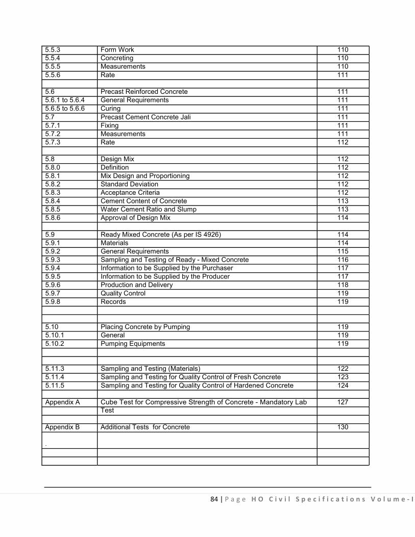
84 | P a g e H O C i v i l S p e c i f i c a t i o n s V o l u m e - I
5.5.3 Form Work 110 5.5.4 Concreting 110 5.5.5 Measurements 110 5.5.6 Rate 111 5.6 Precast Reinforced Concrete 111 5.6.1 to 5.6.4 General Requirements 111 5.6.5 to 5.6.6 Curing 111 5.7 Precast Cement Concrete Jali 111 5.7.1 Fixing 111 5.7.2 Measurements 111 5.7.3 Rate 112 5.8 Design Mix 112 5.8.0 Definition 112 5.8.1 Mix Design and Proportioning 112 5.8.2 Standard Deviation 112 5.8.3 Acceptance Criteria 112 5.8.4 Cement Content of Concrete 113 5.8.5 Water Cement Ratio and Slump 113 5.8.6 Approval of Design Mix 114 5.9 Ready Mixed Concrete (As per IS 4926) 114 5.9.1 Materials 114 5.9.2 General Requirements 115 5.9.3 Sampling and Testing of Ready - Mixed Concrete 116 5.9.4 Information to be Supplied by the Purchaser 117 5.9.5 Information to be Supplied by the Producer 117 5.9.6 Production and Delivery 118 5.9.7 Quality Control 119 5.9.8 Records 119 5.10 Placing Concrete by Pumping 119 5.10.1 General 119 5.10.2 Pumping Equipments 119 5.11.3 Sampling and Testing (Materials) 122 5.11.4 Sampling and Testing for Quality Control of Fresh Concrete 123 5.11.5 Sampling and Testing for Quality Control of Hardened Concrete 124 Appendix A Cube Test for Compressive Strength of Concrete - Mandatory Lab 127
Test Appendix B Additional Tests for Concrete 130 .

85 | P a g e H O C i v i l S p e c i f i c a t i o n s V o l u m e - I
Appendix C Register of Work Test of Concrete 134 Appendix D List of Equipments required for Site Laboratory 136
Annexure A - Sampling of Concrete 138 Annexure B - Concrete Mix Information to be Supplied by the 138 Purchaser Annexure C - Calibration and Weighing Equipment Accuracy 139 Annexure D - Delivery Ticket Information 140
Fig. 5.1, 5.2 & Typical set up of Steel Wall Form Work and Ties 141 5.3 Fig. 5.4 & 5.5 Typical Standard Units and Components of Form Work 144 Fig. 5.6 & 5.7 Typical Arrangements of Column Form Work. 146 Fig. 5.8 Typical details of Beam Head and Stiffener 148 Fig. 5.9 Typical details of Multi-Stage Shuttering 149 Fig. 5.10 to Details of Expansion Joints 150 5.23 Fig. 5.24 & Seismic Separation Joints, Details at Floor and Roof Level 155 5.25 Fig. 5.26 Construction Joints 156 Fig. 5.27 & 5.28 Encasing Rolling Steel Sections 157
.

86 | P a g e H O C i v i l S p e c i f i c a t i o n s V o l u m e - I
LIST OF MANDATORY TESTS
Materia l Clause Tes t Fie ld/ Tes t Min, quantity of Frequency of
labor- proce- materia l for tes ting atory te s t dure carrying out the
tes t 1 2 3 4 5 6 7
Reinforced 5.4.1 (a) Slump Field/Lab Appen- (i) 20 cum in (i) Every 20 cum or cement test dix ‘D’ of Cases of part thereof concrete Chapter column, (Nominal 4 slabs, beams
and connected columns
5.4.9.1 (b) Cube Lab Appen- (i) 5 cum in (i) Every 5 cum or Test dix ‘A’ case of part thereof
column (ii) 20 cum for (ii) Every 20cum or
slabs, beams part thereof and connected columns
(iii) 20 cum for (iii) -Do- other R.C.C. work for all other small items and where R.C.C. done in a day is less than 5 cum test may be Carried out as r equired by E ngineer- in-Charge
.

87 | P a g e H O C i v i l S p e c i f i c a t i o n s V o l u m e - I
1 2 3 4 5 6 7 Reinforced Coarse 50 cum or part Cement Aggre- thereof & also on Concrete gates each change of (Design source Mix) Fine 50 cum or part
Aggre- thereof & also on gates each change of
source Cement 50 MT or on each
change of source Fresh (a) Slump Field Appen- 10 cum 50 cum for R.C.C. Concrete test dix ‘D’ of work including in all
Chapter other small 4 location. R.C.C.
done in a day is less than 50 cum test may be carried out as required by Engineer-in-Charge
Fresh (b) Cube Lab Appen- 10 cum or part 50 cum or 10 Concrete Test dix ‘A’ thereof batches of 5-7 cum
each for R.C.C. work in all location taken together. R.C.C. done in a day is less than 50 cum test may be carried out as required by Engineer-in-Charge
Reinforced Coarse 50 cum or part Cement Aggre- thereof & also on Concrete gates each change of (Ready source Mix) Fine 50 cum or part
Aggre- thereof & also on gates each change of
source Cement 50 MT or on each
change of source Fresh (a) Slump Field/Lab Appendix 10 cum 50 cum for R.C.C. Concrete test ‘D’ of work including in all
Chapter 4 other small location. R.C.C. done in a day is less than 50 cum test may be carried out as required by Engineer-in-Charge
.

88 | P a g e H O C i v i l S p e c i f i c a t i o n s V o l u m e - I
1 2 3 4 5 6 7 Fresh (b) Cube Lab Appen- 10 cum or part 50 cum or 10 batches Concrete Test dix ‘A’ thereof of 5-7 cum each for
R.C.C. work i n al l location - taken together. R.C.C. done in a day is less than 50 c um t est may be carried out as required b y E ngineerin-Charge
Steel for 5.1.3 (A) Physical (a) For (b) For Reinforced Test and consign- consign- cement chemical ment below ment concrete tests 100 tonnes over 100
tonnes (i) under (i) Under
10 mm 10 mm dia, one dia, sample one for each sample 25 for tonnes each or part 40 thereof tonnes
(ii) 10 mm or part to 16 thereof mm dia (ii) 10 mm one to 16 sample mm, for each one 35 sample tonnes for or part each thereof 45
(iii) over 16 tonnes mm dia or part one thereof sample (iii) over for each 16 mm 45 dia, tonnes one or part sample thereof for
each 50 tonnes orpart thereof
.

89 | P a g e H O C i v i l S p e c i f i c a t i o n s V o l u m e - I
LIST OF BUREAU OF INDIAN STANDARDS CODES
S l. No. I.S . No. Subject
1. IS 226 Structural Steel 2. IS 432 (Part I) Specification for mild steel and medium tensile steel bars and hard drawn
steel wire for concrete reinforcement part-I mild steel and medium tensile steel bars.
3. IS 432 (Part II) Specification for mild steel and medium tensile steel bars and hard drawn steel wire for concrete reinforcement - Part-II hard drawn steel wire.
4. IS 456 Code of Practices for plain and Reinforced concrete. 5. IS 516 Method of test for strength of concrete. 6. IS 716 Specification for pentachlorophenol 7. IS 1199 Method of sampling and analysis of concrete. 8. IS 1200 (Part II) Method of measurement of building and civil engineering work - concrete
work 9. IS 1200 (Part V) Method of measurement of building and civil engineering work - concrete
work (Part 5- Form work) 10. IS 1566 Specification for hard drawn steel wire fabric for concrete requirement. 11. IS 1599 Method for bend test 12. IS 1343 Code of Practice for Pre-stressed Concrete 13. IS 1608 Method for tensile testing of steel products 14. IS 1786 Specification for high strength deformed steel and wires for concrete
reinforcement. 15. IS 1791 Specification for batch type concrete mixes 16. IS 2502 Code of practice for bending and fixing of bars for concrete
reinforcement. 17. IS 2751 Recommended practice for welding of mild steel plain and deformed bars
for reinforced construction. 18. IS 4925 Batch plants specification for concrete batching and mixing plant 19. IS 4926 Ready - Mixed Concrete 20. IS 6523 Specification for precast reinforced concrete door, window frames 21. IS 10262 Recommended guidelines for concrete mix design 22. IS 13311 Indian standard for non-destructive testing of concrete. Method of test for
(Part I) ultrasonic pulse velocity 23. IS 13311 Indian standard for non-destructive testing of concrete. Method of testing
(Part II) by rebound hammer. .

91 | P a g e H O C i v i l S p e c i f i c a t i o n s V o l u m e - I
(v) In env ironment subjected to aggressive chloride or sulphate at tach in particular, use of f ly ash admixed or PPC based concrete is recommended. In cases, where structural concrete is exposed to excessive magnesium s ulphate, fly a sh substitution/content s hall be l imited to 18% by weight. Special type of cement w ith low C3A content may also be al ternatively used. D urability criteria l ike minimum binder content and maximum water /binder ratio also need to be given due consideration in such environment.
(vi) Wet curing period shall be enhanced to a minimum of 10 days or its equivalent. In hot & arid regions, the minimum curing period shall be 14 days or its equivalent.
5.1.3 Steel for Reinforcement
5.1.3.1 The steel used for reinforcement shall be any of the following types: (a) Mild steel and medium tensile bars conforming to IS 432 (Part I)
(b) High strength deformed steel bars conforming to IS 1786
(c) Hard drawn steel wire fabric conforming to IS 1566
(d) Structural steel conforming to Grade A of IS 2062
(e) Thermo-mechanically treated (TMT) Bars.
5.1.3.2 Elongation percent on gauge length is 5.65 A where A is the cross sectional areas of the test piece. 5.1.3.3 Mild steel is not recommended for the use in structures located in earthquake zone subjected to severe damage and for structures subjected to d ynamic loading (o ther than w ind l oading) such as railway and highway bridges. 5.1.3.4 Welding of reinforcement bars covered in this specification shall be done in accordance with the requirements of IS 2751.
Nominal m ass/weight : The tolerance on m ass/ weight f or round and square bars shall be t he percentage g iven in Table 5 .1 of the mass/ weight calculated on the basis that the masses of the bar/ wire of nominal diameter and of density 7.85 kg/ cm3 or 0.00785 kg/mm3.

92 | P a g e H O C i v i l S p e c i f i c a t i o n s V o l u m e - I
TABLE 5.1 Tolerance on Nominal Mass
Nominal s ize in mm
(a) Upto and including 10 (b) Over 10, upto and
including 16 (c) Over 16
Tolerance on the Nominal Mass per cent
Batch Individua l sample + Individua l sample for coil (x)
+7 -8 +8
+5 -6 +6
+3 -4 +4
+ for individual sample plus tolerance is not specified (x) for coil batch tolerance is not applicable,
Tolerance shall be determined in accordance with method given in IS 1786. 5.1.3.5 High strength deformed bars & wires shall conform to IS 1786. The physical properties for all
sizes of steel bars are mentioned below in Table 5.2.
TABLE 5.2 Sl. No Property Fe Fe Fe Fe
415 415 D 500 D 550 D (i) 0.2 Per cent Proof 415.0 415.0 500.0 550.0
stress/ yield stress, Min, N/mm2
(ii) Elongation, per cent, 14.5 18.0 16.0 14.5 Min. on gauge length 5.65 A , where A is the corss-sectional area of the test piece.
(iii) Tensile strength, Min 10 Per cent 12 Per cent 10 Per cent 8 Per cent more more than more than the more than than the actual the actual actual 0.2 per the actual 0.2 per cent proof 0.2 per cent cent proof 0.2 per cent stress/yield stress proof stress/ stress/yield proof stress/ but not less than yield stress stress but not yield stress 600.0 N/mm2
but not less less than but not less than 485.0 500.0 N/mm2 than 565.0 N/mm2 N/mm2
(iv) Total elongation at - 5 5 5 maximum force, percent, Min on gauge length 5.65 A , where A is the cross-sectional area of the test piece.
.

93 | P a g e H O C i v i l S p e c i f i c a t i o n s V o l u m e - I
Tests: Selection and preparation of Test sample. All the tests pieces shall be selected by the Engineerin-Charge or his authorized representative either-
(a) From cutting of bars Or
(b) If he so desires, from any bar after it has been cut to the required or specified size and the test piece taken from and any part of it.
In neither case, the test p ieces shall be detached from the bar or coil except in the presence of the Engineer-in-Charge or his authorized representative.
The test pieces obtained in accordance with as above shall be full sections of the bars as rolled and subsequently cold worked and s hall be s ubjected to physical tests w ithout any further modifications. No deduction in s ize by machining or o therwise shall be permissible. No test p iece shall be enacted or otherwise subject to heat treatment. Any straightening which a test piece may require shall be done cold.
Tensile Test: 0.2% proof stress and percentage elongation - This shall be done as per IS 1608, read in conjunction with IS 226. RE- test: This shall be done as per IS 1786.
Rebend test: This shall be done as per IS 1786.
5.1.3.6 Chemical composition of reinforcement bars shall be as per Table 5.3 as follows:-
TABLE 5.3
Constituent Maximum Per cent
Fe 415 Fe 415 D Fe 500 D Fe 550 D Carbon 0.30 0.25 0.25 0.25 Sulphur 0.060 0.045 0.040 0.040 Phosphorus 0.060 0.045 0.040 0.040 Sulphur and 0.110 0.085 0.075 0.075 Phosphorus
5.1.3.7 Thermo Mechanically treated reinforcement bars:
(a) There is no BIS code for TMT bars. The available code BIS 1786 pertains to HSD Bars. Therefore there should be no stipulation that TMT bars should conform to relevant BIS code.
(b) The TMT bars are being produced under valid licence from either of the firms namely Tempcore, Thermex Evcon Turbo & Turbo Quench. These firms have acquired pa tents and are giv ing licences to various producers to produce TMT Bars.
(c) The TMT bars shall conform to IS 1786 pertaining to Fe 415 D or F e 500 D or F e grade of steel as specified.
(d) In design an d c onstruction of reinforced concrete bu ilding in s eismic z one III and ab ove, s teel reinforcement of Grade Fe 415 D shall be us ed. However, high s trength deformed s teel bars, produced by thermo mechanical treatment process of grade F e 415, Fe 500 and F e 550 ha ving elongation more than 14.5. % and conform to other requirements of Fe 415 D, Fe 500 D and Fe 550 D respectively of IS 1786 may also be used for reinforcement. In future, latest provision of IS 456 and IS 13920 or any other relevant code as modified from time to time shall be applicable.
5.1.4 Stacking and Storage Steel for reinforcement shall be s tored in such a w ay as to prevent distorting and c orrosion. Care
shall be taken t o pr otect t he r einforcement f rom ex posure t o s aline at mosphere dur ing s torage,
94 | P a g e H O C i v i l S p e c i f i c a t i o n s V o l u m e - I
fabrication and us e. It may be ac hieved by treating the surface of reinforcement with cement wash or by suitable methods. Bars of different classifications, sizes and lengths shall be stored separately to facilitate issue in such sizes and lengths to cause minimum wastage in cutting from standard length.
5.2 FORM WORK (CENTRING & SHUTTERING) 5.2.1 Form Work
Form work shall include all temporary or permanent forms or moulds required for forming the concrete which is cast-in-situ, together with all temporary construction required for their support.
5.2.2 Design & Tolerance in Construction Form work shall be des igned and c onstructed to the shapes, l ines and di mensions shown on t he
drawings with the tolerance given below. (a) Deviation f rom s pecified dimension of c ross section of columns and beams (b) Deviation f rom dimensions of f ootings (i) Dimension in Plan
(ii) Eccentricity in plan (iii) Thickness
+12 mm -6 mm
(+ 5 0 mm ( -12 mm 0.02 t imes t he w idth of t he f ooting in t he di rection of dev iation but n ot more than 50 mm. + 0.05 times the specified thickness.
(Note- These tolerance apply to concrete dimensions only, and n ot to pos itioning of vertical s teel or dowels).
5.2.3 General Requirement
It shall be strong enough to withstand the dead and l ive loads and forces caused by ramming and vibrations o f concrete and other incidental l oads, imposed upo n i t du ring and a fter casting o f concrete. I t shall be made sufficiently rigid by using adequate number of ties and braces, screw jacks or hard board wedges where required shall be provided to make up any settlement in the form work e ither before or during the placing of concrete.
Form shall be so constructed as to be removable in sections in the des ired sequence, without damaging the surface of concrete or disturbing other sections, care shall be taken to see that no piece is keyed into the concrete.
5.2.3.1 Material for Form Work (a) Propping a nd Cente ring : All propping and centering should be either of steel tubes with
extension pieces or built up sections of rolled steel.
5.2.3.2 (a) Centering/Staging : Staging should be as designed with required extension pieces as approved by Engineer-in-Charge to ensure proper slopes, as per design for slabs/ beams etc. and as per levels as shown in drawing. All the staging to be either of Tubular steel structure with adequate bracings as approved or made of built up structural sections made form rolled structural steel sections.

95 | P a g e H O C i v i l S p e c i f i c a t i o n s V o l u m e - I
(b) In case of structures with two or more floors, the weight of concrete, centering and shuttering of any upper floor being cast shall be suitably supported on one floor below the top most floor already cast.
(c) Form work and concreting of upper floor shall not be done until concrete of lower floor has set at least for 14 days.
5.2.3.3 Shuttering: Shuttering used shall be of sufficient stiffness to avoid excessive deflection and joints shall be tightly butted to avoid leakage of s lurry. If required, rubber ized lining of material as approved by the Engineer-in-Charge shall be provided in the joints. Steel shuttering used or c oncreting should be sufficiently stiffened. The steel shuttering should also be properly repaired before use and properly cleaned to avoid stains, honey combing, seepage of slurry through joints etc.
(a) Runner J ois ts : RSJ, MS Channel or any other suitable section of the required s ize shall be us ed as runners. (b) Assembly of beam head over props. Beam head is an ado pter that f its snugly on t he head plates of props to provide wider support under beam bottoms. (c) O nly steel shuttering shall be u sed, except for unavoidable portions and very small works for which 12 mm thick water proofing ply of approved quality may be used.
5.2.3.4 Form work shall be properly designed for self weight, weight of reinforcement, weight of fresh concrete, and in addition, the various l ive loads l ikely to be imposed during the construction process (such as workmen, materials and equipment). In case the height of centering exceeds 3.50 metres, the prop may be provided in multi-stages. A typical detail of multistage shuttering is given in Fig. 5.9.
5.2.3.5 Camber: Suitable camber shall be provided in horizontal members of structure, especially in cantilever spans to counteract the effect of deflection. The form work shall be so assembled as to provide for camber. The camber for beams and slabs shall be 4 mm per metre (1 to 250 ) or as directed by the Engineer-in-Charge, so as to offset the subsequent deflection, For cantilevers the camber at free end shall be 1/50th of the projected length or as directed by the Engineer-in-Charge. 5.2.3.5.1 Typical arrangement of form work for ‘beams, columns and walls’ are shown in Figures 5.1 to 5.8 and form secured by wall ties is shown in Fig. 5.3.
5.2.3.6 Walls : The form faces have to be kept at fixed distance apart and an arrangement of wall ties with spacer tubes or bolts is considered best. A typical wall form with the components identified is given in Fig. 5.1, 5.2 & 5.3. The two shutters of the wall are to be k ept in place by appropriate t ies, braces and studs, some of the accessories used for wall form are shown in Fig. 5.3. 5.2.3.7 Removal of Form work (Stripping Time) : In normal c ircumstance and w here various types of cements are used, forms, may generally be removed after the expiry of the following periods: Type of Form work Minimum pe riod Minimum pe riod Minimum pe riod
Be fore S triking Be fore S triking Be fore S triking Form work for Form work for OPC Form work for OPC 33 grade 43 grade PPC
(a) Vertical form work to columns, 16-24 h 16-24 h 24-36 h walls, beams
.


97 | P a g e H O C i v i l S p e c i f i c a t i o n s V o l u m e - I
The second categories of shuttering oils / leavening agents are Polymer based water soluble Compounds. They are available as concentrates and when used diluted with water in the ratio of 1:20 or as per manufacturer specifications. Th e di luted solution i s applied b y brush a pplications on t he shuttering both of steel as well as ply wood. The solution is applied after every use.
5.2.4.2 The design of form work shall conform to sound Engineering practices and relevant IS codes.
5.2.5 Form Work Proper form work should be adopted for concreting so as to avoid honey combing, blow holes, grout
loss, s tains or discoloration of concrete etc . P roper and accurate a lignment and profile o f f inished concrete surface will be ensured by proper designing and erection of form work which will be approved by Engineer-in-Charge.
Shuttering surface before concreting should be free from any defect/ deposits and full cleaned so as to give perfectly straight smooth concrete surface. Shuttering surface should be therefore checked for any damage to its surface and excessive roughness before use.
Contractor to take care of following before placing the reinforcement; (a) If there are any excavations nearby which may influence the safety of form works, corrective and strengthening action must be taken.
(b) (i) The bearing soil must be sound and well prepared and the sole plates shall bear well on the ground.
(ii) Sole plates shall be properly seated on their bearing pads or sleepers. (iii) The bearing plates of steel props shall not be distorted. (iv) The steel parts on the bearing members shall have adequate bearing areas.
(c) Safety measures to prevent impact of t raffic, scour due t o water etc. should be t aken. Adequate precautionary measures shall be taken to prevent accidental impacts etc.
(d) B racing, struts and ties shall be i nstalled along with the progress of form work to ensure strength and s tability of f orm work at intermediate s tage. Steel sections (especially deep sections) shall be adequately restrained against tilting, over turning and form work should be restrained against horizontal loads. All the securing devices and bracing shall be tightened.
(e) When adjustable steel props are used. They should: 1. be undamaged and not visibly bent. 2. have the steel pins provided by the manufacturers for use. 3. be restrained laterally near each end. 4. have means for centralizing beams placed in the forkheads.
(f) Screw adjustment of adjustable props shall not be over extended. (g) D ouble wedges shall be pr ovided for adjustment of the form to the required position wherever any settlement/ elastic shorting of props occurs. Wedges should be used only at the bottom end of single prop. Wedges should not be too steep and one of the pair should be tightened/ clamped down after adjustment to prevent shifting.
(h) No member shall be eccentric upon vertical member.
(i) The number of nuts and bolts shall be adequate.
(j) All provisions of the design and/or drawings shall be complied with.
98 | P a g e H O C i v i l S p e c i f i c a t i o n s V o l u m e - I
(k) Cantilever supports shall be adequate.
(l) Props shall be directly under one another in multistage constructions as far as possible.
(m) Guy ropes or stays shall be tensioned properly.
(n) There shall be ad equate provision for the movements and operation of v ibrators and o ther construction plant and equipment.
(o) Required camber shall be provided over long spans.
(p) Supports shall be adequate, and in plumb within the specified tolerances.
5.2.6 Measurements
5.2.6.1 General : The form work shall include the following: (a) Splayed edges, notching, allowance for overlaps and passing a t angles, sheathing battens, strutting, bolting, nailing, wedging, easing, striking and removal.
(b) All supports, struts, braces, wedges as well as mud sills, piles or other suitable arrangements to support the form work.
(c) Bolts, wire, ties, clamps, spreaders, nails or any other items to hold the sheathing together.
(d) Working scaffolds, ladders, gangways, and similar items.
(e) F illeting to form s top chamfered edges of splayed ex ternal angles no t exceeding 20mm w ide t o beams, columns and the like.
(f) Where required, the temporary openings p rovided in the forms for pouring concrete, inserting vibrators, and c leaning holes for removing rubbish from the interior of the sheathing before pouring concrete.
(g) Dressing with oil to prevent adhesion and
(h) Raking or circular cutting
5.2.6.2 Classification of Measurements : Where it is stipulated that the form work shall be paid for separately, measurements shall be t aken of the area of shuttering in contact with the concrete surface. Dimensions of the form work shall be measured correct to a cm. The measurements shall be taken separately for the following.
(a) Foundations, footings, bases of columns etc. and for mass concrete
(b) Walls (any thickness) including attached pilasters, buttresses, plinth and string courses etc.
(c) Suspended floors, roofs, landings, shelves and their supports and balconies.
(d) Lintels, beams, plinth beams, girders, bressummers and cantilevers.
(e) Columns, pillars, piers, abutments posts and struts.
(f) Stairs (excluding landings) except spiral staircase.
(g) Spiral staircases (including landings).

99 | P a g e H O C i v i l S p e c i f i c a t i o n s V o l u m e - I
(h) Arches, Domes, vaults, shells roofs, arch ribs, curvilinear shaped folded plates
(i) Extra for arches, domes, vaults exceeding 6 m span other than curvilinear shaped
(j) Chimneys and shafts.
(k) Well steining.
(l) Vertical and horizontal fins individually or forming box, louvers and bands.facias and eaves board
(m) Waffle or ribbed slabs.
(n) Edges of slabs and br eaks in f loors and w alls (to be m easured in running metres where below 200 mm in width or thickness).
(o) Cornices and mouldings.
(p) Small surfaces, such as cantilevers ends, brackets and ends of steps, caps and boxes to pilasters and columns and the like.
(q) Chullah hoods, weather shades, Chajjas, corbels etc. including edges and
(r) Elevated water reservoirs.
5.2.6.3 Centering, and shuttering where exceeding 3.5 metre height in one floor shall be measured and paid for separately. 5.2.6.4 Where i t is not specifically stated in the description of the item that form work shall be paid for separately, the rate of the RCC item shall be deemed to include the cost of form work. 5.2.6.5 No deductions from the shuttering due to the openings/ obstructions shall be made if the area of each open ings/ obstructions does not exceed 0.4 square metre. Nothing extra shall be pa id for forming such openings.
5.2.6.6 Form work of el ements measured under c ategories of ar ches, ar ch r ibs, dom es, s piral s taircases, well s teining, shell roofs, curvilinear folded plates & curvilinear eaves board, circular shafts & chimneys shall not qualify for extra rate for circular work.
5.2.6.7 Extra for circular work shall be admissible for surfaces circular or curvilinear in plan or in elevation beyond the straight edge of supporting beam in respective mode of measurement. However, there may be many different types of such structures. In such cases, extra payment shall be made judiciously after deducting areas where shuttering for circular form work is not involved.
5.2.7 Rate The rate of the form work includes the cost of labour and m aterials required for al l the operations
described above.

100 | P a g e H O C i v i l S p e c i f i c a t i o n s V o l u m e - I
5.3 REINFORCEMENTS 5.3.1 General Requirements
Steel conforming to Para 5.1.3 for reinforcement shall be c lear and f ree from loose mill scales, dust, loose rust, coats of paints, oil or other coating which may destroy or reduce bond. It shall be stored in such a way as to avoid d istortion and to prevent deterioration and corrosion. Prior to assembly o f reinforcement on no account any oily substance shall be used for removing the rust.
5.3.1.1 Assembly of Reinforcement : Bars shall be bent correctly and accurately to the size and shape as shown in the detailed drawing or as directed by Engineer-in-Charge. Preferably bars of full length shall be us ed. N ecessary cutting and s traightening i s al so i ncluded. O verlapping o f bar s, w here necessary shall be done as directed by the Engineer-in-Charge. The overlapping bars shall not touch each other and these shall be kept apart with concrete between them by 25mm or 1 1/4 times the maximum size of the coarse aggregate whichever is greater. But where this is not possible, the overlapping bars shall be bound together at intervals not exceeding twice the dia. of such bars with two strands annealed steel wire of 0.90 mm to 1.6 mm twisted tight. The overlaps/ splices shall be staggered as per directions of the Engineer-in-Charge. But in no case the overlapping shall be pr ovided in more than 50% of cross sectional area at one section.
5.3.1.2 Bonds and Hooks Forming End Anchorages: Reinforcement s hall be bent and f ixed i n accordance with procedure specified in IS 2502, code of practice of bending and fixing of bars for concrete reinforcement. The details of bends and hooks are shown below for guidance.
(a) U-Type Hook In case of mild steel plain bars standard U type hook shall be provided by bending ends of rod into semicircular hooks having clear diameter equal to four times the diameter of the bar. Note: In case of work in seismic zone, the size of hooks at the end of the rod shall be eight times the diameter of bar or as given in the structural drawings.
(b) Bends Bend forming anchorage to a M.S. plain bar shall be bent with and internal rad ius equal to two times the diameter of the bar with a m inimum length beyond the bend equal to four t imes the diameter of the bar.
5.3.1.3 Anchoring Bars in Tension : Deformed bars m ay be used without en d anchorages pr ovided, development length equipment is satisfied. Hooks should normally be provided for plain bars in tension. Development length of bars will be determined as per IS: 456.
5.3.1.4 Anchoring Bars in Compression : The anchorage length of straight bar in compression shall be equal to th e ‘Development le ngth’ of bar s in compression as specified in IS: 45 6. T he proj ected length of hooks, bend and straight lengths beyond bend, i f provided for a bar in compression, shall be considered for development length.
5.3.1.5 Binders, stirrups, links etc. : In case of binders, stirrups, links etc. the straight portion beyond the curve at the end shall be not less than eight times and nominal size of bar.
5.3.2 Welding of Bars Wherever facility for electric arc welding or gas pressure welding is available, welding of bars can be
done i n l ieu o f o verlap. T he l ocation a nd t ype of welding shall be go t app roved by t he Engineer-in- Charge. Welding shall be as per IS 2751 and 9417.
5.3.3 Placing in Position 5.3.3.1 Fabricated reinforcement bars shall be placed in position as shown in the drawings or as directed by the Engineer-in-charge. The bars c rossing one another shall be t ied together at every intersection with two strands of annealed steel wire 0.9 to 1.6 mm thickness twisted t ight to make the skeleton of the steel work rigid so that the reinforcement does not get displaced during deposition of concrete.

101 | P a g e H O C i v i l S p e c i f i c a t i o n s V o l u m e - I
Tack welding in crossing bars shall also be permitted in lieu of binding with steel wire if approved by Engineer-in-Charge.
5.3.3.2 The bars shall be kept in correct position by the following methods: (a) In case of beam and slab construction pre-cast cover blocks in cement mortar 1:2 (1 cement : 2 coarse sand) about 4x4 cm section and of thickness equal to the specified cover shall be placed between the bars and shuttering, so as to secure and maintain the requisite cover of concrete over reinforcements. (b) In case of cantilevered and doubly reinforced beams of slabs, the vertical distance between the horizontal bars shall be maintained by introducing chairs, spacers or support bars of steel at 1.0 mere or at shorter spacing to avoid sagging. (c) In case of columns and walls, the vertical bars shall be kept in position by means of timber templates with slots accurately cut in them: or with clock of cement mortar 1:2 (1 cement: 2 coarse sand) of required size suitable tied to the reinforcement to ensure that they are in correct position during concreting. (d) In case of other R.C.C. s tructure such as arches, domes, shells, storage tanks etc. a combination of cover blocks, spacers and templates shall be used as directed by Engineer-in-Charge.
5.3.3.3 Tolerance on Placing of Reinforcement : Unless otherwise s pecified by t he E ngineer-in- Charge, reinforcement shall be placed within the following tolerances:
Tolerance in spacing (a) For effective depth, 200 mm or less +10 mm (b) For effective depth, more than 200 mm + 15 mm
5.3.3.4 Bending at Construction Joints : Where reinforcement bars are bent as ide at construction joints and afterwards bent back into their original position care should be t aken to ensure that at no time the radius of the bend is less than 4 bar diameters for plain mild steel or 6 bar diameter for deformed bars. Care shall also be taken when bending back bars to ensure that the concrete around the bar is not damaged.
5.3.3.5 Cover : The minimum nominal cover to meet durability requirements shall be as under:-
Exposure Nomina l Concrete cover in mm not le s s than Mild 20 Moderate 30 Severe 45 Very severe 50 Extreme 75
Notes : 1. For main reinforcement upto 12 mm diameter bar for mild exposure the nominal cover may be reduced by 5 mm.
2. U nless specified otherwise, ac tual concrete cover should not deviate f rom the required nominal cover by + 10 mm.
3. For exposure c ondition ‘severe’ and ‘ very s evere’ reduction o f 5 mm may b e made, where concrete grade is M35 and above.
4. Nominal cover to meet specified period of fire resistance shall not be less than as given in Table 16A of IS 456.

102 | P a g e H O C i v i l S p e c i f i c a t i o n s V o l u m e - I
5.3.4 Measurement
Reinforcement in cluding authorized s pacer bar s and lappages s hall be m easured in length o f different diameter, as actually (not more than as specified in the drgs.) used in the work nearest to a centimetre and their weight calculated on the basis of standard weight given in Table 5.4 below. In case actual unit weight of the bars is less than standard unit weight, but within variation, in such cases weight of reinforcement shall be calculated on the basis of actual unit weight. Wastage and unauthorized overlaps shall not be paid for. Annealed steel wire required for b inding or tack welding shall not be measured, its cost being included in the rate of reinforcement.
Where tack welding is used in lieu of binding, such welds shall not be measured. Chairs separators etc. shall be provided as directed by the Engineer-in-Charge and measured separately and paid for.
TABLE 5.4
Cross Sections Area and Mass of Steel Bar Nomina l Size mm Cros s sectiona l Area Sq.mm Mass per metre Run Kg.
6 28.3 0.222 8 50.3 0.395
10 78.6 0.617 12 113.1 0.888 16 201.2 1.58 20 314.3 2.47 25 491.1 3.85 28 615.8 4.83 32 804.6 6.31 36 1018.3 7.99 40 1257.2 9.86
Note: These are as per clause 6.2 of IS 1786.
5.3.5 Rate The ra te for re inforcement shall i nclude the cost of labour and materials required for all operations
described abo ve s uch as cleaning of reinforcement ba rs, straightening, c utting, hook ing bending, binding, placing in position etc. as required or directed including tack welding on crossing of bars in lieu of binding with wires. 5.4 CONCRETING 5.4.0 The concrete shall be as specified under chapter 4 concrete work. The proportion by volume or by the weight of ingredients shall be as specified. 5.4.1 Consistency
The concrete which will flow s luggishly into the forms and around the reinforcement w ithout any segregation of coarse aggregate f rom the mortar shall be used. The consistency shall depend on whether the concrete is vibrated on or hand tamped, it shall be determined by slump test as prescribed in sub-head “concrete” under workability - requirement. 5.4.2 Placing of Concrete 5.4.2.1 Concreting shall be commenced only after Engineer-in-Charge has inspected the centering, shuttering and reinforcement as placed and pas sed the same. Shuttering shall be c lean and free from al l shavings, saw dust, pieces of wood, or other foreign material and surfaces shall be t reated as prescribed in 5.2.4.
.


104 | P a g e H O C i v i l S p e c i f i c a t i o n s V o l u m e - I
in-Charge. Number of such joints shall be kept to minimum. The joints shall be kept at places where the shear force is the minimum. These shall be straight and shall be at right angles to the direction of main reinforcement. Construction joints should comply with IS 11817.
5.4.4.2 In case of columns the joints shall be hor izontal and 10 t o 15 c m below the bottom of the beam running into the column head. The portion of the column between the stepping off level and the top of the slab shall be concreted with the beam.
5.4.4.3 When stopping the concrete on a vertical plane in slabs and beams, and approved stop board (see Fig. 26C) shall be pl aced with necessary slots for reinforcement bars or any other obstruction to pass the bars freely without bending. The construction joints shall be keyed by providing a triangular or trapezoidal fillet nailed on the stop board. Inclined or feather joints shall not be permitted. Any concrete flowing through the joints of stop board shall be removed soon after the initial set. When concrete is stopped on a horizontal plane, the surface shall be roughened and cleaned after the initial set.
5.4.4.4 When the work has to be resumed, the joint shall be thoroughly cleaned with wire brush and loose particles removed. A coat of neat cement slurry at the rate of 2.75 kg of cement per square metre shall then be applied on the roughened surface before fresh concrete is laid.
5.4.5 Expansion Joints Expansion joints shall be provided as shown in the structural drawings or as indicated in Fig. 5.10 to 5.25 or as directed by Engineer-in-Charge, for the purpose of general guidance. However i t is recommended that structures exceeding 45 m in length shall be divided by one or more expansion joints. The f illing of these joints with bi tumen f iller, bi tumen felt or any such material and provision of copper plate, etc. shall be pai d for separately in running metre. The measurement shall be t aken two places of decimal stating the depth and width of joint.
5.4.6 Curing After the concrete has begun to harden i .e. about 1 to 2 hours after i ts laying, i t shall be protected
from quick drying by covering with moist gunny bags, sand, canvass Hessian or any other material approved by the Engineer-in-Charge. After 24 hours of laying of concrete, the surface shall be c ured by ponding with water for a minimum period of 7 d ays from the date of placing of concrete in case of OPC and at least 10 days where mineral admixtures or blended cements are used. The period of curing shall not be less than 10 days for concrete exposed to dry and hot weather condition.
5.4.7 Finishing 5.4.7.1 In case of roof slabs the top surface shall be finished even and smooth with wooden trowel, before the concrete begins to set. Sprinkling of dry cement while finishing shall not be resorted to.
5.4.7.2 Immediately on removal of forms, the R.C.C. work shall be examined by the Engineer-in-Charge, before any defects are made good.
(a) The work that has sagged or contains hone y c ombing to an ex tent det rimental t o structural safety or architectural concept shall be rejected as given in Para 5.4.9.4 for visual inspection test. (b) Surface defects of minor nature may be accepted. On acceptance of such a work by the Engineer-in-Charge, the same shall be rectified as follows:
1. Surface defects which require repair when forms are removed, usually consist of bulged due to movement of forms, ridges at form joints, honey-combed areas, damage resulting from the stripping of forms and bolt holes, bulges and ridges are removed by careful chipping or tooling and the surface is then rubbed with a grinding stone. Honey-combed and other defective areas must be chipped out, the edges being cut as straight as possible and perpendicularly to the surface, or preferably slightly under cut to provide a key at the edge of the patch.

105 | P a g e H O C i v i l S p e c i f i c a t i o n s V o l u m e - I
2. Shallow patches are first treated with a coat of thin grout composed of one part of cement and one part of fine sand and then filled with mortar similar to that used in the concrete. The mortar is placed in layers not more than 10mm thick and each layer is given a scratch finish to secure bond with the succeeding layer. The last layer is finished to match the surrounding concrete by floating, rubbing or tooling on formed surfaces by pressing the form material against the patch while the mortar is still plastic. 3. Large and deep patches require f illing up with concrete held in place by forms. Such patches are reinforced and carefully dowelled to the hardened concrete.
4. Holes left by bolts are filled with mortar carefully packed into places in small amounts. The mortar is mixed as dry as possible, with just enough water so that it will be tightly compacted when forced into place.
5. T iered holes ex tending r ight through the concrete may be f illed w ith mortar w ith a pr essure gun similar to the gun used for greasing motor cars.
6. Normally, patches appear darker than the surrounding concrete, possibly owing to the presence on their surface of less cement laitance. Where uniform surface colour is important, this defect shall be remedied by adding 10 to 20 percent of white Portland cement to the patching mortar, the exact quantity being determined by trial. 7. The same amount of care to cure the materials in the patches should be taken as with the whole structure. Curing must be started as soon as possible, after the patch is finished to prevent early drying. Damp Hessian may be used but in some locations it may be difficult to hold it in place. A membrane curing compound in these cases will be most convenient.
(c) The exposed surface of R.C.C. work shall be plastered with cement mortar 1:3 (1 cement : 3 fine sand) of thickness not exceeding 6 mm to give smooth and even surface true to line and form. This plastering will be measured and paid separately under plastering item.
(d) The surface which is to receive plaster or where it is to be joined with brick masonry wall, shall be properly roughened immediately after the shuttering is removed, taking care to remove the laitance completely without disturbing the concrete. The roughening shall be done by hacking. Before the surface is plastered, it shall be cleaned and wetted so as to give bond between concrete and plaster.
RCC work shall be done carefully so that the thickness of plaster required for finishing the surface is not more than 6 mm.
(e) The surface of RCC slab on which the cement concrete or mosaic floor is to be laid shall be roughened with brushes while the concrete is green. This shall be done without disturbing the concrete.
5.4.8 Strength of Concrete The compressive strength on the work tests for different mixed shall be as given in Table 5.5 below:-

106 | P a g e H O C i v i l S p e c i f i c a t i o n s V o l u m e - I
TABLE 5.5
Concrete Mix (Nominal Mix on Compress ive Strength in (Kg/ sq cm)
Volume bas is ) 7 days ’ 28 days ’
1:1:2 210 315 1:1.5:3 175 265 1:2:4 140 210
5.4.9 Testing of Concrete
5.4.9.0 Regular mandatory tests on the workability of the fresh concrete shall be done to achieve the specified compressive strength of concrete. These will be of two types
(a) Mandatory Lab, Test (b) Mandatory Field Test Results of Mandatory Field Test will prevail over mandatory Lab. Test.
5.4.9.1 Cube Test for Compressive Strength of Concrete - Mandatory Lab Test : Mandatory tests shall be carried out as prescribed in Appendix A of Chapter 5.
5.4.9.2 Additional Test : Additional test, if required, shall be carried out as prescribed in Appendix B of Chapter 5.
5.4.9.3 Slump Test : This test shall be carried out as prescribed in sub-head 4 of concrete.
5.4.9.4 Visual Inspection Test : The concrete will be inspected after removal of the form work as described in Para 5.4.7.2 The question of carrying out mandatory test or o ther tests described in Appendix A and B (Para 5.4.9.1 and 5.4.9.2) will arise only after satisfactory report of visual inspection.
The concrete is liable to be rejected if: (i) It is porous or honeycombed as per Para 5.4.7.2 (a). (ii) Its placing has been interrupted without providing a proper construction joint. (iii)The r einforcement has be en displaced bey ond t olerance s pecified or construction t olerances have not been met.
However, the hardened concrete may be accepted after carrying out suitable remedial measures to the
satisfaction of the Engineer-in-Charge at the risk and cost of the contractor.
5.4.10 Standard of Acceptance - for Nominal Mix
5.4.10.1 Mandatory Lab. Test : For concrete sampled and tested as prescribed in Appendix A of Chapter 5, the following requirement shall apply.
5.4.10.2 Out of six sample cubes, three cubes shall be tested at 7 days and remaining three cubes at 28 days.
5.4.10.3 7 days’ Tests Sampling: The average of the strength of three specimen shall be accepted as the compressive
strength of the concrete provided the variation in strength of individual specimen is not more than + 15% of the average. D ifference between t he m aximum and m inimum strength s hould not e xceed 3 0% of average s trength o f t hree s pecimen. I f the di fference bet ween maximum and m inimum strength ex ceeds 30% of the average strength, then 28 days’ test shall have to be carried out.

107 | P a g e H O C i v i l S p e c i f i c a t i o n s V o l u m e - I
S trength: If the actual average strength of sample accepted in para ‘sampling’ above is equal to or
higher than specified strength upto +15% then strength of the concrete shall be considered in order.
In case the actual average strength of sample accepted in the above para is lower than the specified or higher b y m ore t han 15% then 28 da ys’ test shall hav e t o be c arried out t o det ermine the compressive strength of concrete cubes.
5.4.10.4 28 days’ Test (a) The average of the strength of three specimen be accepted as the compressive strength of the concrete provided the strength of any individual cube shall neither be less than 70% nor higher than 130% of the specified strength. (b) If the actual average strength of accepted sample exceeds specified strength by more than 30% the Engineer-in-Charge, if he so desires, may further investigate the matter. However, if the strength of any individual cube exceeds more than 30% of specified strength, it will be restricted to 130% only for computation of strength.
(c) If the actual average strength of accepted sample is equal to or higher than specified strength upto 30% then strength of the concrete shall be considered in order and the concrete shall be accepted at full rates.
(d) If the actual average strength of accepted sample is less than specified strength but not less than 70% of the specified strength, the concrete may be accepted at reduced rate at the discretion of Engineer-in-Charge (see Para 5.4.13.2).
(e) If the actual average strength of accepted sample is less than 70% of specified strength, the Engineer-in-Charge shall reject the defective portion of work represented by sample and nothing shall be paid for the rejected work. Remedial measures necessary to retain the structure shall be taken at the risk and cost of contractor. If, however the Engineer-in-Charge so desires, he may order additional tests (See Appendix B of Chapter 5) to be carried out to ascertain if the structure can be retained. All the charges in connection with these additional tests shall be borne by the contractor.
5.4.11 Measurements 5.4.11.1 Dimensions shall be m easured nearest to a cm except for the thickness of slab which shall be measured correct to 0.5 cm. The areas shall be worked out nearest to 0.01 Sq. mt. The cubical contents shall be worked out to nearest 0.01 cubic metre.
5.4.11.2 Reinforced cement concrete whether cast-in-situ or pre cast s hall be c lassified and measured separately as follows.
(a) Raft, footing, bases of columns and mass concrete etc. all work up to plinth level, column up to plinth level, plinth beams.
(b) Wall (any thickness) including a ttached pil asters, buttresses plinth and s tring course, fill ets, column, pillars, piers, abutments, post and struts etc.
(c) Suspended floors, roofs, landings and balconies.
(d) Shelves
(e) Chajjas
(f) Lintel, beams and bressummers.
(g) Columns, pillars, piers, abutments, posts and struts.

108 | P a g e H O C i v i l S p e c i f i c a t i o n s V o l u m e - I
(h) Stair-cases including waist or waist less slab but excluding landing except in (i) below.
(i) Spiral stair-case (including landing).
(j) Arches, arch ribs, domes and vaults.
(k) Chimneys and shafts.
(l) Well steining.
(m) Vertical and horizontal fins individually or forming box, louvers and facias.
(n) Kerbs, steps and the like.
(o) String courses, bands, coping, bed plates, anchor blocks, plain window sills and the like.
(p) Mouldings as in cornices, window sills etc.
(q) Shell, dome and folded plates.
(r) Extra for shuttering in circular work in plan.
5.4.11.3 Work under the following categories shall be measured separately. (a) Rafts, footings, bases of columns etc. and mass concrete. (b) All other items upto floor two level. (c) From floor two level to floor three level and so on. (d) R.C.C. above roof level shall be measured along with R.C.C. Work in floor just below.
5.4.11.4 No deduction shall be made for the following:
(a) Ends of dissimilar materials (e.g. Joists, beams, post, girders, rafter, purlins, trusses, corbels steps etc.) upto 500 sq cm in cross-section.
(b) Opening upto 0.1. sqm. Note: In calculating area of openings upto 0.1 sqm the size of opening shall include the thickness of any separate lintels or sills. No extra labour for forming such openings or voids shall be paid for.
(c) The volume occupied by reinforcement. (d) The volume occupied by water pipes, conduits etc. not exceeding 25 sq cm each in cross sectional area. Nothing extra shall be paid for leaving and finishing such cavities and holes.
5.4.11.5 Measurement shall be t aken before any rendering is done i n concrete members. Measurement will not include rendering. The measurement o f R .C.C. work bet ween v arious uni ts shall be r egulated as below:
(a) Slabs shall be taken as running continuously through except when slab is monolithic with the beam. In that case it will be from the face to face of the beam. (b) Beams shall be measured from face to face of columns and shall be including haunches, if any, between columns and beam. The depth of the beam shall be from the bottom of slab to the bottom of beam if beam and slab are not monolithic. In case of monolithic construction where slabs are integrally connected with beam, the depth of beam shall be from the top of the slab to the bottom of beam.
(c) The columns measurements shall be taken through.

109 | P a g e H O C i v i l S p e c i f i c a t i o n s V o l u m e - I
(d) Chajjas along with its bearing on wall shall be measured in cubic metre nearest to two places of decimal. When Chajjas is combined with lintel, slab or beam, the projecting portion shall be measured as Chajjas, built in bearing shall be measured as per item of lintel, slab or beam in which Chajjas bears.
(e) Where the band and lintels are of the same height and the band serves as lintel the portion of the band to be measured as lintel shall be for clear length of opening plus twice the over all depth of band.
5.4.12 Tolerances Subject to the condition that structural safety is not impaired and architectural concept does not
hamper, t he tolerances i n di mensions of R.C.C. m embers shall be as s pecified in t he d rawings. Whenever these a re not s pecified, the permissible t olerance s hall be dec ided b y t he E ngineer in-Charge after consultations with the Designer, if necessary.
When tolerances in dimensions are permitted, following procedure for measurement shall apply.
(a) If the actual dimension of R.C.C. members do not exceed or decrease the design dimensions of the members plus or minus tolerance limit specified above, the design dimensions shall be taken for the purpose of measurement. (b) I f t he actual d imensions exceed the design dimensions by more than the tolerance l imit, the design dimensions only shall be measured for the purpose of payment. (c) I f the ac tual dimensions decrease more than the tolerance l imit specified, the ac tual dimensions of the RCC members shall be taken for the purpose of measurement and payment. (d) For acceptance of RCC members whose dimensions are not exactly as per design dimensions, the decision of Engineer-in-Charge shall be final. For the purpose of payment, however, the clarification as given in Para a, b & c above shall apply.
5.4.13 Rate
5.4.13.1 The rate included the cost of materials and labour involved in all the operations described above except for the cost of centring and shuttering. 5.4.13.2 On the bas is of mandatory lab tests, in case of actual average compressive s trength being less than specified strength but upto 70% of specified strength, the rate payable shall be in the same proportion as actual average compressive strength bears to specified compressive strength.
Example: 1. Average compressive strength in 80% of specified strength. Rate payable shall be 80% of agreement rate.
2. In case average compressive strength is less than 70% of the specified strength, the work represented by the sample shall be rejected. 3. However, on the basis of mandatory field tests, where they prevail, the rates of the work represented by samples showing actual compressive strength less than specified strength shall be worked out as per Para 5.4.10.5 (D-3) above. In addition, Engineer-in-charge may order for additional tests (see Appendix ‘B’ of chapter 5) to be carried out at the cost of contractor to ascertain if the portion of structure where in concrete represented by the samples had been used, can be retained on the basis of these tests. Engineer-in-Charge may take further remedial measured as necessary to retain the structure at the risk and cost of the contractor.

110 | P a g e H O C i v i l S p e c i f i c a t i o n s V o l u m e - I
5.4.13.3 Where throating or plaster drip or moulding is not required to be provided in RCC Chajjas, deduction for not providing throating or plaster drip or moulding shall be made from the i tem of R .C.C. in Chajjas. The measurement for deduction item shall be m ade in running metres correct to a c m of the edge of Chajjas. 5.4.13.4 No extra payment for richer mix which projects into any member from another member during concreting of junctions of beams and columns etc. will be made except to the extent structurally considered necessary and when so indicated in the structural drawings. The payment for work done under items of different mixed shall be limited strictly to what is indicated in the structural drawings.
5.5 ENCASING ROLLED STEEL SECTIONS
5.5.1 General Requirements Before concrete work is started, the Engineer-in-Charge shall check that all rolled steel sections to be
encased, have been erected truly in position. The sections shall be unpainted and shall be wire brushed to remove the loose rust/ scales etc. Where so specified, un-galvanised metal, having mesh or perforations large enough to permit the f ree passage of 12.5 mm nominal s ize aggregate through them shall be wrapped round the section to be encased and paid for separately.
5.5.2 Wrapping 5.5.2.1 In case of columns, the wrapping shall be arranged as illustrated in Fig. 5.27 to pass through the centre of the concrete covering. The wrapping of the e ntire length o f the columns be carried out in stages and no stage shall cover more than 1.5 metre of height of columns. Successive wrappings shall be carried out only after the immediate adjacent wrapping has been encased in concrete. The surface and edges of the flanges of the steel columns shall have a concrete cover of not less than 50mm. The wrappings of the successive stages shall be tied together. 5.5.2.2 In the case of beams and grillages, the wire mesh or expanded metal shall be wrapped round the lower flange of the beam as illustrated in Fig. 5.28 and the wrapping shall be suspended by wire hangers 5 mm diameter p laced at about 1.2 metres centres. The surfaces and edges of the s teel sections shall have a concrete cover of not less than 50mm. The wrapping shall pass through the centre of the concrete covering at the edges and soffits of the flanges.
5.5.3 Form Work shall be as prescribed in 5.2.
5.5.4 Concreting Concrete shall consist of a mix of 1:2:4 (1 cement : 2 coarse and : 4 graded stone aggregate of 12.5
mm nominal s ize) un less a r icher mix is specified. The mix shall be poured solidly around the steel sections and a round the wrapping by vibrating the concrete into position. Consistency of concrete, Placing of concrete and i ts compaction, curing, f inishing and s trength of concrete shall be a s described in 5.4.
5.5.5 Measurements The length shall be measured correct to one cm and other dimensions correct of 0.5 cm. The cement
concrete shall be measured as per gross dimensions of the encasing exclusive of the th ickness of plaster. No deduction shall be m ade for the volume of s teel sections, expanded m etal, mesh or any other reinforcement used therein. However, in case of boxed stanchions or girders, the boxed portion only shall be deducted.
Fabric r einforcement such as expanded m etal s hall be m easured s eparately in s quare m etres s tating the mesh and size of strands.
The description shall include the bending of the fabric as necessary, Racking or c ircular cutting and waste shall be included in the description.

111 | P a g e H O C i v i l S p e c i f i c a t i o n s V o l u m e - I
5.5.6 Rate The r ate s hall i nclude t he cost of materials and labour r equired f or al l t he op erations des cribed a bove
except the cost of fabric reinforcement. The cost of providing and erecting steel section and wire hangers shall be paid for separately.
5.6 PRECAST REINFORCED CONCRETE 5.6.1 General Requirements
Precast reinforced concrete uni ts such as columns, fencing po sts, door an d w indow f rames, l intels, Chajjas, copings, sills , shelves, slabs, louvers etc. shall be of grade of mix as specified and cast in forms or moulds. The forms/ moulds shall be of fibre glass or of steel sections for better finish. Provision shall be made i n t he f orms and moulds t o ac commodate fixing d evices su ch a s n ibs, cl ips, h ooks, b olts a nd forming o f notches and holes. The contractor may precast the units on cement or steel p latform which shall be adequately oiled provided the surface finish is of the same standard as obtained in form. Each unit shall be cast in one operation. 5.6.2 Concrete used for precasting the uni ts should be w ell proportioned, mixed, placed and t horoughly compacted by vibrations or tamping to give a dense concrete free from voids and honey combing. 5.6.3 Precast ar ticles shall have a dens e surface finish showing no coarse aggregate and shall have not cracks or crevices l ikely to assist in disintegration of concrete or rusting of steel or other defects that would interfere with the proper placing of the units. All angle of the precast units with the exception of the angles resulting from the splayed or chamfered faces shall be true r ight angles. The arises shall be clean and sharp except those specified or shown to be rounded. The wearing surface shall be true to the lines. On being fractured, the interior of the units should present a clean homogeneous appearance. 5.6.4 The longitudinal reinforcement shall have a minimum cover of 12 mm or twice the diameter of the main bar, w hichever i s m ore, un less ot herwise di rected in respect of all items ex cept fencing posts or electric posts where the minimum cover shall be 25 mm.
5.6.5 Curing After having been cast in the mould or form the concrete shall be adequately protected during setting in
the first stages of hardening from shocks and from harmful effects of frost, sunshine, drying winds and cold. The concrete shall be cured at least for 7 days from the date of casting.
5.6.6 The precast articles shall be matured for 28 days before erection or being built in so that the concrete shall have sufficient strength to prevent damage to units when first handled. 5.6.8 Precast units shall be s tored, transported and placed in position in such as manner that they will not be overstressed or damaged.
5.7 PRECAST CEMENT CONCRETE JALI 5.7.0 The jali shall be of cement concrete 1:2:4 (1 cement 2 coarse sand:4 stone aggregate 6 m m nominal size) reinforced with 1.6 mm thick mild steel wire, unless otherwise specified.
5.7.1 Fixing The jali shall be set in position true to plumb and level before the joints sills and soffits of the
openings are plastered. I t shall then be properly grouted with cement mortar 1:3 (1 cement :3 coarse sand) and rec hecked for levels. F inally the jambs, sills and soffits shall be p lastered embedding the jali uniformly on all sides.
5.7.2 Measurements The jali shall be measured for i ts gross superficial area. The length and breadth shall be m easured
correct to a cm. The thickness shall not be less than that specified.

112 | P a g e H O C i v i l S p e c i f i c a t i o n s V o l u m e - I
5.7.3 Rate The rate shall be inclusive of materials and labour involved in all the operations described above
except plastering of jambs, sills and soffits, which will be paid for under relevant items of plastering.
5.8 DESIGN MIX 5.8.0 Definition
Design mix concrete is that concrete in which the design of mix i .e. the determination of proportions of c ement, a ggregate & water is ar rived as t o hav e target mean s trength for s pecified grade o f concrete. The minimum mix of M25 shall be us ed in al l structural elements in both load bearing & RCC framed construction.
5.8.1 Mix Design and Proportioning 5.8.1.1 Mix proport ions shall be designed to ensure that the workability of fresh concrete is suitable for conditions of handling and placing, so that after compaction it surrounds all reinforcement and completely fills the formwork. When concrete is hardened, it shall have the stipulated strength, durability and impermeability.
5.8.1.2 Determination of the proportions by weight of cement, aggregates and water shall be based on design of the mix.
5.8.1.3 As a t rial the manufacturer of concrete may prepare a p reliminary mix according to provisions of SP: 23. Reference may also be made to ACI 211.1-77 for guidance. 5.8.1.4 Mix design shall be tried and the mix proportions checked on the basis of tests conducted at a recognized laboratory approved by the Engineer-in-Charge.
5.8.1.5 All concrete proportions for various grades of concrete shall be designed separately and the mix proportions established keeping in view the workability for various structural elements, methods of placing and compacting. 5.8.1.6 Before using an admixture in concrete, i ts performance shall be evaluated by comparing the properties of concrete with the admixture and concrete without any admixture. Chloride content of admixture should be dec lared by the manufacturer of adm ixture and shall b e w ithin l imits s tipulated by IS:9103.
5.8.2 Standard Deviation 5.8.2.1 Standard deviation calculations of test results based on tests conducted on the same mix design for a particular grade designation shall be done in accordance with IS 456.
5.8.3 Acceptance Criteria 5.8.3.1 Compressive Strength : The concrete shall be deemed to comply with the strength requirements when both the following condition are met:
(a) The mean s trength determined f rom any group of four consecutive test results complies w ith the appropriate limits in col 2 of Table 5.6. (b) Any individual test result complies with the appropriate limits in col. 3 of Table 5.6.
5.8.3.2 Flexural Strength : When both the following conditions are met, the concrete complies with the specified flexural strength.
(a) The mean s trength determined from any group of four consecutive test results exceeds the specified characteristic strength by at least 0.3 N/mm2.
(b) The strength determined from any test result is not less than the specified characteristic strength/ 0.3 N/mm2.
113 | P a g e H O C i v i l S p e c i f i c a t i o n s V o l u m e - I
5.8.3.3 Quantity of Concrete Represented by Strength Test Results : The quantity of concrete represented b y a g roup o f four consecutive t est results shall i nclude the batches from which the first and last samples were taken together with all intervening batches.
For the individual test result requirements gi ven in col 3 of Table 5.6 or i n i tem (b) of 5.8.3.2. Only t he particular batch from which the sample was taken shall be at risk.
Where the mean rate of sampling is not specified the maximum quantity of concrete that four consecutive test results represent shall be limited to 60 m3. 5.8.3.4 If the concrete is deemed not to comply pursuant to 5.8.3 the structural adequacy of the parts affected shall be investigated and any consequential action as needed shall be taken. 5.8.3.5 Concrete of each grade shall be assessed separately.
5.8.3.6 Concrete is liable to be rejected if it is porous or honey-combed, its placing has been interrupted without providing a proper construction joint, the reinforcement has been displaced beyond the tolerances specified, or construction tolerances have not been met. However, the hardened concrete may be accepted af ter carrying out suitable remedial measured to the satisfaction of t he E ngineer-in- Charge.
5.8.4 Cement Content of Concrete 5.8.4.1 For al l grades of concrete manufactured/produced, minimum cement content in the concrete shall be 330 kg per c ubic metre of concrete. Also, i rrespective of the gr ade of concrete the m aximum cement content shall not be more than 500 kg per cubic metre of concrete. These limitations shall apply for all types of cements of all strengths. 5.8.4.2 Actual cement content in each grade of con crete for various conditions of variable shall be established by design mixes within the limits specified in Para 5.8.4.1 above. 5.8.5 Water Cement Ratio and Slump 5.8.5.1 In proportioning a particular mix, the manufacturer/ producer/ contractor shall give due consideration to the moisture content in the aggregates, and the mix shall be so designed as to restrict the maximum free water cement ratio to less than 0.5.
5.8.5.2 Due consideration shall be given to the workability of the concrete thus produced. Slump shall be controlled on the basis o f placement in different s ituations. For normal m ethods of placing concrete, maximum slump shall be restricted to 100 mm when measured in accordance with IS 1199.

114 | P a g e H O C i v i l S p e c i f i c a t i o n s V o l u m e - I
TABLE 5.6
Characteristic Compressive Strength Compliance Requirement (Clause 5.8.3.1 and 5.8.3.3)
Specified Grade Mean of the Group of 4 Non- Individual Test Results in N/mm3
Overlapping Consecutive test Results in N/mm3
(1) (2) (3) M15 ≥ fck + 0.825 x established standard ≥ fck-3 N/mm2
deviation (r ounded off t o n earest 0.5 N/mm2) or fck +3 N/mm2
Whichever is greater M20 ≥ fck + 0.825 x established standard ≥ fck-4 N/mm2
or deviation (rounded off to nearest 0.5 above N/mm2)
or fck +4 N/mm2, Whichever is greater
NOTE - In the absence of established value of standard deviation, the values given in Table may be assumed, and attempt should be made to obtain results of 30 samples as early
as possible to establish the value of standard deviation.
5.8.6 Approval of Design Mix 5.8.6.1 The producer/ manufacturer/ contractor of concrete shall submit details of each trial mix of each grade of concrete designed f or v arious workability c onditions t o t he Engineer-in-Charge f or h is comments and approval. Concrete of any particular design mix and grade shall be produced/ manufactured for works only on obtaining written approval of the Engineer-in-Charge. 5.8.6.2 For any change in quality/ quantity in the ingredients of a particular concrete, for which mix has been des igned ear lier and app roved by the E ngineer-in-Charge, the m ix has to b e r edesigned and approval obtained again. 5.9 READY MIXED CONCRETE (as per IS 4926) 5.9.1 Materials 5.9.1.1 Selection and Approval of Materials : Materials used should satisfy the requirements for the safety, structural performance durability and appearance of t he f inished s tructure, taking full account of the environment to which it will be s ubjected. The selection and use of materials shall be in accordance with IS 456. Materials used shall conform to the relevant Indian Standards applicable. Where materials are used which are not covered by th e provisions of the relevant Indian Standard, there should be satisfactory dat a on their s uitability and as surance o f qual ity c ontrol. R ecords and det ails o f performance of such m aterials should be m aintained. A ccount should be t aken of po ssible i nteractions an d compatibility between IS 4926 and materials used. A lso, prior permission of the purchaser shall be obtained before use of such materials. 5.9.1.2 Cement : Cement used for concrete shall be in accordance with the requirements of IS 456. 5.9.1.3 Mineral Admixtures : Use of mineral admixtures shall be permitted in accordance with the provisions of IS 456.

115 | P a g e H O C i v i l S p e c i f i c a t i o n s V o l u m e - I
5.9.1.4 Aggregates : Aggregates used for concrete shall be i n accordance with the requirement o f IS 456. Unless otherwise agreed testing frequencies for aggregates in plant shall be as given IS 4926.
5.9.1.5 Chemical Admixtures (i) U se of chemical admixtures shall be permitted in accordance, with the p rovisions o f IS 456 and IS 9103.
(ii) It shall be the responsibility of the producer to establish compatibility and suitability of any admixture with the other ingredients of the mix and the determine the dosage required to give the desired effect.
(iii) Admixtures should be stored in a manner that prevents degradation of the product and consumed within the time period indicated by the admixture supplier. Any vessel containing an admixture in the plant or taken to site by the producer shall be clearly marked as to its content.
(iv) When offering or delivering a mix to a purchaser it should be indicated if such a mix contains an admixture or combination of admixtures or not. The admixtures may be identified generically and should be declared on the delivery ticket.
(v) The amount of admixture added to mix shall be recorded in the production record. In special circumstances, if necessary, additional dose of admixture may be added at project site to regain the workability of concrete with the mutual agreement between the producer and the purchaser.
5.9.1.6 Water : Water used shall be in accordance with the requirement of IS 456. Unless otherwise agreed, the testing frequencies for water shall be as given in Annex A.
The use of re-cycled water is encouraged as long as concrete of satisfactory performance can be produced and steps are taken to monitor the build up of chlorides in any recirculated water and that any subsequent ad justments t o the mix des ign are made to ens ure that an y o verall l imit on c hloride c ontents is satisfied. The addition of any recycled water shall be monitored and controlled to meet these requirements.
The total amount of water added t o the mix shall be r ecorded in the production record. The water content of concrete shall be regulated by controlling i ts workability or by measuring and adj usting the moisture contents of its constituent materials. The producer’s production staff and truck-mixer, drivers shall be m ade aware of the appropriate responses to variations in concrete consistency of a par ticular mix caused by normal variations in aggregate moisture content or grading.
5.9.2 General Requirements
5.9.2.1 Basis of Supply : Ready-mixed concrete shall be supplied having the qual ity and the quantity in accordance with the requirement agreed with the purchaser or his agent. Notwithstanding th is, the concrete supplied shall generally comply with requirements of IS 456.
All concrete w ill be supplied and invoiced in terms of cubic metres (full or pa rt) of compacted f resh concrete. All proportioning is to be carried out by mass except water and admixture, which may be measured by volume.
5.9.2.2 Transport of Concrete : Ready-mixed concrete shall be t ransported from the mixer to the point of placing as rapidly as practicable by m ethods that will maintain the required workability and will prevent segregation, loss of any constituents or ingress of foreign matter or w ater. The concrete shall be placed as soon as possible after delivery, as close as is practicable to its final position to avoid re-handling or moving the concrete horizontally by vibration. If required by the purchaser the producer can utilize

116 | P a g e H O C i v i l S p e c i f i c a t i o n s V o l u m e - I
admixtures to slow down the rate of workability loss, however this does not remove the need for the purchaser to place the concrete as rapidly as possible. The purchaser should plan his arrangements so as to enable a full load of concrete to be discharged within 30 minutes of arrival on site.
Concrete shall be transported in a truck-mixer unless the purchaser agrees to the use of nonagitating v ehicles. W hen non -agitating v ehicles ar e us ed, t he m ixed c oncrete s hall be pr otected from gain or loss of water. 5.9.2.3 Time in Transport : The general requirement is that concrete shall be discharged from the truck-mixer within 2 h of the time of loading. However, a longer period may be permitted if retarding admixtures are used or in cool humid weather or when chilled concrete is produced. The time of loading shall start from adding the mixing water to the dry mix of cement and aggregate or of adding the cement to the wet aggregate whichever is applicable.
Ready-mixed concrete plant shall have test facilities at its premises to carry out routine tests as per the requirement of the standard.
5.9.3 Sampling and Testing of Ready-Mixed Concrete 5.9.3.1 Point and Time of Sampling : For the assessment of compliance of ready-mixed concrete, the point and time of sampling shall be at discharge from the producer’s delivery vehicle or from the mixer to the s ite or w hen delivered i nto t he purchaser’s vehicle. I t i s c ritical t hat t he s ampling procedure a nd equipment used enables as representative a sample as possible to be taken of the quantity of concrete delivered (see Annex A).
The sampling may be carried out jointly by the purchaser and the supplier with its frequency mutually agreed upon. However, it will not absolve the supplier of his responsibility from supplying in concrete as per the requirement given in this standard or otherwise agreed to where so permitted in the standard. 5.9.3.2 Workability : The test for acceptance is to be performed upon the producer’s delivery vehicle discharge on site or upon discharge into the purchaser’s vehicle. lf discharge from the producers’ vehicle is delayed on site due to lack of preparedness on behalf of the purchaser then the responsibility passes to the purchaser after a delay of more than 30 min.
The w orkability s hall be within t he f ollowing limits o n t he s pecified v alue as a ppropriate: Slump ± 25 mm or 1/3 of the specified value, whichever is less. Compacting factor : ± 0.03, where the specified value is 0.90 or greater,
± 0.04, where the specified value is less than 0.90 but more than 0.80, ± 0.05, where the specified value is 0.80 or less.
Flow table test may be s pecified for concrete, for very high workability (see IS 9103) Acceptance
criteria for spread (flow) are to be established between the supplier and the purchaser.
5.9.3.3 Specified Strength (i) Compliance shall be assessed against the requirements of IS 456 or other agreed Indian Standard. The purchaser may perform his sampling and testing or may enter into an arrangement with the producer to provide his testing requirements. (ii) Unless otherwise agreed between the parties involved, the minimum testing frequency to be applied by the producer in the absence of a recognized ready-mixed concrete industry method of production control should be one sample for every 50 m3 of production or every 50 batches, whichever is the greater frequency. Three test specimens shall be made up for each sample for testing at 28 days (see also IS 456).
117 | P a g e H O C i v i l S p e c i f i c a t i o n s V o l u m e - I
In order to get a r elatively quicker idea of the quality of c oncrete, optional test on beams for modulus of rupture at 72 ± 2 h or at 7 days or compressive strength test at 7 days may be carried out in addition to 28 days compressive strength t est. F or t his p urpose t he v alue should b e arrived at based on actual testing. In al l cases 28 days compressive strength shall alone be the criteria for acceptance or rejection of the concrete.
(iii) The purchaser shall i nform the producer if hi s requirements for sampling and t esting are higher than one sample every 50 m3 or 50 batches, whichever is the greater frequency.
5.9.3.4 Additional Compliance Criteria : Any addi tional compliance criteria shall be dec lared to the producer by the purchaser prior to supply and shall be mutually agreed upon in terms of definition, tolerance frequency of assessment, method of test and significance result. 5.9.3.5 Non-Compliance : The action to be t aken in case of non-compliance shall be declared and mutually agreed upon. 5.9.4 Information to be Supplied by the Purchaser 5.9.4.1 The purchaser shall provide to the producer the details of the concrete mix or mixes required by him and all pertinent information on the use of the concrete an d t he s pecified req uirements. P rior t o supply taking place, it is recommended that a meeting is held between the purchaser and the producer. Its objective to clarify operational matters such as notice to be given prior to delivery, delivery rate, the name of t he purc hasers aut horized repr esentative w ho w ill coordinate del iveries, an y req uirements f or additional services such as pumping, on site testing or training, etc. 5.9.4.2 Designed Mixes : Where the purchaser specifies a designed mix to be supplied i t is essential that al l relevant information is conveyed to the producer. In order to assist in this, the format given in Annex B may be completed and forwarded to the producer at the time of enquiry. 5.9.4.3 Prescribed Mixes : The concrete mix shall be specified by i ts constituent materials and the properties or quantities of those constituents to produce a concrete with the required performance. The assessment of the mix proportions shall f orm an essential par t of the compliance requirements. The purchaser shall provide the producer w ith al l pertinent i nformation on the use of the concrete and the specified requirements. In order to assist in t his, the format given in Annex B may be followed with suitable modifications as applicable to prescribed mixes.
5.9.5 Information to be Supplied by the Producer When requested, the producer shall provide the purchaser with the following information before any
concretes is supplied: (a) Nature and source of each constituent material,
(b) Source of supply of cement,
(c) Proposed proportions or quantity of each constituent/ m3 of fresh concrete.
(d) Generic type(s) of the main active constituent(s) in the admixture;
(e) Whether or not the admixture contains chlorides and i f so, the chloride content of the admixture expressed as a percentage of chloride ion by mass of admixture;
(f) Where more than one admixture is used, confirmation of their compatibility and
(g) Initial and final setting t ime o f c oncrete when ad mixture is us ed at adopted dos age (tested as per IS 8142).

118 | P a g e H O C i v i l S p e c i f i c a t i o n s V o l u m e - I
5.9.6 Production and Delivery 5.9.6.1 Materials Storage and Handling
(i) Cement : Separate storage for Different types and grades of cement shall be provided. Containers may be us ed to s tore cement o f di fferent t ypes provided these are emptied before loading new cement. Bins or silos shall be weatherproof and permit free flow and efficient discharge of the cement. In case, the cement remains in storage for more than 3 months, the cement shall be retested before use and shall be rejected, if it fails to conform to any of the requirements given in the relevant Indian Standard.
(ii) Dry Pulverized Fue l Ash and Other Minera l Admixture s : Suitable separate arrangement for storage of pulverized fuel ash, silica fume, metakeolin, rice husk ash, ground granulated blast furnace slag such as for cement, shall be provided, in the plants utilizing these materials.
(iii) Aggregates (Coa rse and Fine) : Stockpiles shall be free draining and arranged to avoid contamination and to prevent intermingling with adjustment material.
(iv) Water : An adequate supply shall be provided and when stored on the plant such storage facilities shall be designed to minimize the risk of contamination.
(v) Chemica l Admixture s : Tanks or drums containing liquid admixtures shall be clearly labelled for identification purposes and stored in such a way to avoid damage, contamination or the effects of prolonged exposure to sunlight (if applicable). Agitation shall be provided for liquid admixture, which are not stable solutions.
5.9.6.4 Mixing
(i) Washing Out Water : Before loading concrete materials or mixed concrete into either a stationary mixer or truck mixer any water retained in the mixing drum for washing out purposes shall be completely discharged. (ii) Stationary or Centra l Mixers : Stationary mixers shall not be loaded in excess of the manufacturer’s rated capacity. The mixing time shall be measured from the time all the materials required for the batch, including water, are in the drum of the mixer. The mixing time shall not be less than that recommended by the manufacturer. Where a continuous mixing plant is used, the complete mixing time shall be sufficient to ensure that the concrete is of the required uniformity. (iii) Truck Mixers : When a truck mixer is used for the partial or complete mixing of concrete, mixing shall be considered to commence from the moment when all the materials required for the batch, including water, are in the rotating drum of the mixer.
Truck or agitators shall not be loaded in excess of the manufacturer’s rated capacity. In order to produce a satisfactory mix, and where there is no data available to establish di fferent period and speed of revolutions, mixing shall continue for not less than 60 revolutions of the truck mixer drum at a r ate of not less than 7 r evolutions/min. All completely truck mixed concrete shall be visually inspected for uniformity prior to leaving the plant.
When a t ruck mixer or agi tator is used for t ransporting concrete which has been m ixed before leaving the plant, the concrete shall be agitated during transit and remixed at the site for at least 2 min so that the concrete is of the required uniformity.
(iv) Condition of Mixers : Stationary and truck mixers shall be maintained in an efficient and clean condition with no appreciable build up of hardened concrete or cement in the mixing drum, on the mixing blades, or on the loading hopper or discharge chutes.

119 | P a g e H O C i v i l S p e c i f i c a t i o n s V o l u m e - I
5.9.6.5 Delivery Ticket : Immediately before discharging the c oncrete at the po int of del ivery, the producer or h is representative s hall pr ovide the pur chaser w ith a preprinted de livery ticket for ea ch delivery of concrete on which is printed, s tamped or written the m inimum information detailed invoicing as per Annex D. 5.9.7 Quality Control
Quality control of ready-mixed concrete to be achieved through, forward control, immediate control and retrospective control. 5.9.7.4 Mix Performance : The producer shall be responsible for ensuring that suitable control procedures are in place ensure for Design and Prescribed mixes.
5.9.7.5 Stock Control of Materials : The producer shall operate a materials stock control procedure to enable verification of total quantities used and to confirm that only approved materials have been received.
5.9.7.6 Complaints : The producer shall have a procedure in place to enable the diagnosis and correction of faults identified from complaints.
5.9.8 Records Records shall be m aintained by the producer to provide confirmation of the quality and q uantity and
quantity of concrete produced. The records shall be retained for the purposes of these requirements for a period of at least one year. They shall cover the following aspect:
(a) Production and delivery: (i) Batching instruction (ii) Batching Records, (iii) Delivery tickets, and (iv) Equipment calibration and plant maintenance.
(b) Materials and production control: (i) Concrete production and materials purchase, usage and stocks, and (ii) Certificates or test results for materials.
(c) Production quality Control: Control test results.
5.10 PLACING CONCRETE BY PUMPING 5.10.1 General
Concrete conveyed by pressure through either rigid pipes or flexible hoses and discharged directly into the desired area is termed as pumped concrete.
Method of applying pressure to concrete is by pumps. Pumps to be used shall be ei ther of the two types as mentioned below:-
(A) Piston type pumps (B) Squeeze pressure type pumps.
Compressed air pressure pumps shall not be used in the works.
5.10.2 Pumping Equipments 5.10.2.1 Piston Pumps : P iston pump to be used in the works shall consist of a r eceiving hopper for mixed concrete, an inlet valve, an outlet valve, and the pump shall be a twin-piston pump.
The two pistons shall be so arranged that one piston retracts when the other is moving forward and pushing concrete into the pipe line to maintain a reasonably steady f low of co ncrete. S ingle piston pumps shall not be acceptable.
120 | P a g e H O C i v i l S p e c i f i c a t i o n s V o l u m e - I
Inlet and outlet valve shall be any one of the following types:- - Rotating plug type - Sliding plate type - Guided plunger type - Swing type - Flapper type - Or any combination of the above. The p istons shall be mechanically dri ven using a c rank or chain or hydraulically driven using oil o r
water.
The receiving hopper shall have a minimum capacity of 1.0 cum and the hopper shall be f itted with remixing rotating blades capable of maintaining consistency and uniformity of concrete.
The pr imary power f or pu mps may be s upplied b y gasoline, di esel, or el ectric motors.
The primary power unit and the pump unit may be truck, trailer or skid mounted.
5.10.2.2 Squeeze Pressure Pumps : Squeeze p ressure pum ps s hall c onsist o f a receiving hopp er fitted with re-mixing blades. Re-mixing blades shall be s uch that these can push the concrete into the f lexible hose connected at the bottom of the hopper.
The flexible hose shall pass through a metal drum around the inside per iphery of the drum and come out through the top part of the drum.
The drum shall be m aintained under a very high degree of a v acuum dur ing operation. The drum shall be so f itted with hydraulically operation metal rollers., which when rotating, create a sq ueeze pressure on the flexible hose carrying concrete and forces the concrete out into the pipe line. 5.10.2.3 Effective Range and Discharge of Pumps : Effective range of pumps to be us ed in the work shall be dec ided a fter studying the s ite conditions. However, the minimum horizontal range shall not be less than 150 metres and minimum vertical range shall not be less than 50 metres.
Selection o f pumps bases on di scharge capacity s hall be dec ided a fter s tudying t he requirements for the project. Discharge capacity shall be worked out by the contractors and approval obtained f rom the Engineer-in-Charge. As a gui de l ine f igure the contractor may assume a di scharge capacity of 15 c ubic metre/hour/pump. 5.10.2.4 Pipe Lines : All concrete carrying pipe lines shall generally be rigid pipe lines. Flexible pipe lines may only be used at bend curves in l ines or at discharge ends i f required. Placements of flexible units shall be done j udiciously and c onnected to the pipe l ines only when it meets the approval of the Engineer-in-Charge.
(i) Rigid Line/ Hard Line/ Slick line : Such lines shall be made either of steel or plastic. Aluminium alloy pipes shall not be used.
Minimum pipeline diameter shall be 100 millimetres and shall have normal maximum length of 3 metre in each section connected through couplers.
(ii) Flexible Pipe Line : Flexible lines shall be made out of rubber or spiral wound flexible metal or plastic. The pipe shall again be such that they are in sections of 3 metre length each and connected through couplers. These pipes shall be such that they are interchangeable with rigid lines. While installing flexible units, care shall be taken that there are no links in the pipeline, which is a normal tendency with these pipes having diameter 100 mm and above.

121 | P a g e H O C i v i l S p e c i f i c a t i o n s V o l u m e - I
5.10.2.5 Couplers : Couplers to be used for connecting pipe line sections (either hard or flexible) shall have adequ ate s trength to w ithstand s tresses due to handl ing, misalignments, poor support to pi pe l ines etc.
For hor izontal runs of pipes and for vertical run upto 30 metre height the couplers shall be rated for a minimum pressure of 35 kg/ cm square. Couplers used for rising runs between 30 metre and 50 metre heights shall have a minimum pressure rating of 50 kg/cm square. Couplers shall be designed to allow for replacement of any pipe s ection without displacing other sections. These shall provide for the full internal cross section. These shall provide for the full internal cross section with no constructions or service. Which m ay disrupt the smooth f low of concrete. For pipelines o f size 150m m and abo ve, doubl e togged t ype c oupler with a thick rubber gasket and secondary wedge-take-up is recommended. T ypes of couplers that may be used shall be any of the following:-
- Grooved end coupler
- One piece extended lever swing type couplers
- And full flow oil line type couplers.
5.10.2.6 Other Accessories : Other accessories which shall be catered for, are as under:-
(a) Back up pump of rigid and flexible pipes of varying lengths of similar rating/specifications
(b) Curved sections of rigid pipes
(c) Swivel joints and rotary distributors
(d) Pin and gate valves to prevent back flow in pipe lines
(e) Switch valves to direct the flow into another pipe line
(f) Connection devices to fill forms from the bottom up (g) Splints, ro llers, and other devices for protection of conduit over rock concrete Reinforcing steel and form and to provide lifting and lashing points in the pipe line. (h) Transitions for connecting different sizes of pipe sections
(i) Air vents for downward pumping.
(j) Clean out equipment.
For concreting of columns, walls and scattered small placement, recommendation is made for special cranes or power controlled booms carrying pipe lines with a pendant type concrete delivery hose.
5.10.2.7 Lubricating of Pipe Line Before pumping concrete into the pipeline, the line shall be lubricated with a properly designed
mortar/grout lubricant. This shall be ens ured by starting the pumping operation with a pr operly designed mortar, or w ith a bat ch of regular concrete w ith the coarse aggregate omitted. The quant ity of mortar required as lubricant is dependent on the smoothness and cleanliness of the pipelines. As a guide line, for a 100 mm diameter pipe line of 100 metre length, 0.08 cum to 0.10 cum of mortar should normally be adequate, but this shall not be taken as specified, and the contractor shall establish his requirements.


123 | P a g e H O C i v i l S p e c i f i c a t i o n s V o l u m e - I
Certificate confirming that the use o f a particular brand o f admixture shall not be harmful to concrete in any way.
Certificate confirming the exact dosage of admixture of a particular brand.
Certificate stating the specific purpose for which the admixture is to be used.
Special precautionary measures to be taken in the manufacturer o f concrete when us ing the particular brand of admixture.
Certificate c onfirming that t he ad mixture c onforms t o specifications o f IS 9103 o r to A STM-C260, ASTM - C10, ASTM - C 595 or to ASTM- C 618.
(ii) Engineer-in-Charge at his discretion may require tests to be performed to reconfirm the characteristic properties of any admixture. All such tests shall be done in accordance with IS: 9103.
(iii) All test shall be done in the presence of a representative nominated by the Engineer-in-Charge and a representative of the concrete Manufacturer/ Contractor when tests are performed at the site laboratory. (iv) Expenses for all materials used for testing, sampling procedures and testing including preparing reports shall be borne by the concrete Manufacturer/ Contractor. (v) Rate of concrete is inclusive of cost of admixtures. The contractor shall not be paid anything extra for admixtures required for achieving direct workability without any change in specified water cement ration for RCC/CC work.
5.11.4 Sampling and Testing for Quality Control of Fresh Concrete Fresh concrete shall be tested for (a) Slump (b) Compacting Factor/ Workability (c) Consistency (d) Weight per cubic metre, cement factor and air content
5.11.4.1 Slump
(i) For concrete totally mixed in a central plant, slump shall be checked at:- (a) Immediately during loading of trucks (b) Final placement location (d) At placement location the slump measured shall conform to the design slump. Manufacturer of concrete shall adjust for loss of slump in transit and establish the requirements of design mix. All slump measurements shall be done within a period of 20 minutes from the time cement is added to the mixer.
(ii) For concrete entirely mixed in transit or for shrink mix concrete, slump reading shall be taken at:- (a) Point of discharge from delivery trucks (b) Final placement location In this case also, the slump measured at the final placement location shall conform to the design slump.
(iii) At placement locations, samples for checking slump shall be collected as desired by Engineer-in-charge
(iv) For all s lump checks in the f ield at least two recordings shall be made and the average value taken as the recorded slump.

124 | P a g e H O C i v i l S p e c i f i c a t i o n s V o l u m e - I
(v) Slump readings shall only be a guideline for concrete consistency and shall not be taken as the acceptability criteria for concrete placed at location. All slump test shall be carried out in accordance with IS 1199.
5.11.4.2 Compacting Factor
(i) For concrete whose ordered slump is 50 mm or less, compacting factor test shall be conducted at central batch plant in addition to slump tests mentioned above.
(ii) Compacting factor check shall be done at central batch plant if concrete is totally mixed in plant.
(iii) Laboratory tests for determining compacting factor of concrete shall be done as per manufacturer’s requirements for establishing and controlling the design mix of concrete.
(iv) Compacting factor test shall not be taken as an acceptance criteria and s hall be t reated only as a guideline to workability of concrete.
5.11.4.3 Consistency of Concrete : This test shall be performed only at t he batching p lant l aboratory using a Vee-Bee Consist meter, for determining and predicting the slump of concrete. Number and frequency of these tests shall be based on requirements of the manufacturer of concrete. Care shall be taken in producing mix design of requ ired c haracteristic s trengths o f concrete within l imits of Vee-Bee- Degrees between 1.6 and 4.5 for concrete transported and placed by normal method and between 0.8 and 3.5 for concrete transported and placed by pumping methods.
5.11.4.4 Weight, Cement Factor and Air contents Test : Freshly mixed concrete for every type shall be tested in the batch pl ant laboratory for each batch of concrete produced to determine weight pe r cubic metre of f reshly mixed concrete, cement factor in concrete and the ai r content of the concrete. Frequency and number of test shall be finalized by the manufacturer of concrete in consultation with the Engineer-in-Charge for his requirement of the mode of measurement of concrete produced.
The Engineer-in-Charge may at his discretion require further tests over and above those specified above in para 5.11.4.1 to be conducted on fresh concrete. The manufacturer and the placement contractor shall have to comply with all such requirements.
5.11.5 Sampling and Testing for Quality Control of Hardened Concrete (i) Test on cube crushing strength of concrete in accordance and compliance with IS 456 and IS 456 shall be done as under:-
(a) Sample of fresh concrete shall be taken from concrete at central batch plant mixer while loading delivery trucks or other transport .
(b) Test in specimens made from samples at the batch plant shall only be taken as guidelines test. Only in the case of doubtful result, the Engineer-in-Charge may refer to such guideline results for deciding on the quality of concrete.
(c) For truck mix concrete and shrink mix concrete guideline test specimens shall be made from samples collected at discharge location from mixing trucks. For this purpose first and last 15% of the load shall be omitted while collecting samples.
(d) Frequency of sampling shall be as given below in Table 5.8 for each grade of concrete of different workability’s and for each type of specimens (field test specimens and guideline test specimens) for conducting 28 days crushing strength tests.

125 | P a g e H O C i v i l S p e c i f i c a t i o n s V o l u m e - I
TABLE 5.8
Quantity of concrete Delivered (cum) Number of samples Less than 5 1 6 to 15 2 31 to 50 3 51 and above sample for each 4 plus one additional 50 cum or part
thereof Each sample shall be of adequate quantity so that a minimum of 3 specimen cubes can be made test of the sample in accordance with IS 516.
(e) A ll test specimens shall be made compacted cured and tested in compliance with IS 516 and test result interpreted in accordance with IS 456 for acceptance of concrete strength, field specimens test results shall not be less than values given in Table 5.6.
(f) In addition to 28 d ay crushing strength test on specimens m ade at frequencies specified in para 4 ab ove, early strength tests at 7 day s shall also be c onducted on f ield specimens as well as gu ideline test specimens. Frequency of s ampling for t his set of te st shall also be same as those specified in Table 5.8 above. 7 da y strength shall conform to values g iven in Table 5.5. But these test results even i f conforming to specified values shall only be t aken a guideline values for projecting concrete strength and shall not be construed as conforming to specifications. (g) For each g rade of concrete and for al l workability conditions w ith di fferent water - cement ratios and compositions of admixtures, preliminary test shall be conducted for crushing strength on f inalization to design mix for each type of concrete. Such test shall be c onducted both at 7 days and 28 days under laboratory conditions. Six test specimens shall be made for
7 days test and six test specimens shall be made for 28 days test.
Average of the six test results of di fferent periods shall not be less than those specified in Table 5.5.
(h) Crushing strengths on cubes shall also be conducted during the process of finalization of concrete design m ix. F requency and num ber of such t ests shall be as pe r M ix of requirements of concrete manufacturer.
(i) All test specimens for conducting crushing strength shall be properly labelled for identification indicating:-
(i) Date of making specimen (ii) Grade of concrete (iii) Placement location
(j) In a ddition to c rushing s trength t est o n c oncrete, the Engineer-in-Charge m ay c all f or other tests on hardened concrete. The placement contractor and t he manufacturer of concrete shall comply with all such instructions.
(ii) Non-destructive Tests (a) When the 28 days c rushing values on f ield specimens and / or s pecimens and/or specimens made fo r guideline tes t fall sh ort of s pecified values, or in c ase o f doubtful placement of concrete, t he Engineer-in-Charge s hall c all for no n-destruction t ests on t he s tructure. Such tests may be any one or a combination of the following:- Rebound hammer test Windsor Penetration Probe test Pulse velocity (sonic or Ultrasonic) test Core test Load test

126 | P a g e H O C i v i l S p e c i f i c a t i o n s V o l u m e - I
(b) Interpretation of rebound hammer, Windsor Probe and Pulse velocity test results shall rest with the Engineer-in-Charge.
(c) Core test, if ordered by the Engineer-in-Charge, shall be done in accordance with IS 516. Samples for such test shall be taken from locations to be identified by the Engineer-in-Charge and such samples shall be collected in compliance with IS:1199.
(d) If felt necessary, the Engineer-in-Charge may instruct load testing for any part of the structure based on doubtful concrete strengths. Such test shall be carried out as per details to be provided by the Engineer-in-Charge in consultation with the structural consultants.
(e) The concrete manufacturer/ concrete placement contractor shall arrange for all test to be conducted in accordance with these specifications, including all necessary tools, plants, equipment and material, and shall be responsible for conducting all test at his cost.
(f) All test conducted shall be carried out by qualified technicians employed by th e concrete manufacturer/ concrete placement contractor, in presence of authorized representative of the Engineer-in-Charge.
(g) Engineer-in-Charge shall alone decide where such tests are to be conducted. He may instruct tests to be conducted at laboratories other than the laboratory at concrete manufacturer place and such instructions shall be followed without claiming extra charges on this account.

127 | P a g e H O C i v i l S p e c i f i c a t i o n s V o l u m e - I
APPENDIX A
CUBE TEST FOR COMPRESSIVE STRENGTH OF CONCRETE - MANDATORY LAB TEST
(Clause 5.4.9.1) A-0 One sample (consisting of six cubes 15x15x15 cm shall be taken as often as considered necessary by the Engineer-in-Charge. The test of concrete cubes shall be carried out in accordance with the procedure as described below. A register of cubes shall be maintained at the site of work in Appendix C. The casting of cubes, concrete used for cubes and all other incidental charge, such are curing, carriage to the testing laboratory and testing fees shall be borne by the contractors. A-1 Test Procedure A-1.1 Mould
The mould shall be of size 15 cmx15 cmx15 cm for the maximum nominal s ize of aggregate not exceeding 40 mm. For concrete with aggregate size more than 40 mm size of mould shall be specified by the Engineer-in-charge, keeping in view the fact that the length of size of mould should be about four times the size of aggregate.
The m oulds for t est specimens shall be m ade of non-absorbent material and shall be substantially strong enough t o hold their form dur ing the moulding of test specimens. They shall not vary f rom the standard dimensions by more than one percent. The moulds shall be so constructed that there is no leakage of water f rom the test specimen during moulding. All the cube moulds for particular s ite should, prior to use, be checked for accuracy in dimensions and geometric form and such test should at least be made once a year.
Each mould shall be pr ovided with a bas e plate having a pl ane surface and made of non-absorbent material. This plate shall be large enough in diameter to support t he moulds properly without leakage. Glass plates not less than 6.5mm thick or plain metal not less than 12mm thick shall be us ed for this purpose. A similar p late shall be prov ided for covering the top surface of the test specimen when moulded. Note: Satisfactory moulds can be m ade f rom machine or s teel castings, rolled metal plates or galvanized.
A-1.2 Sample of Concrete Sample of co ncrete for test specimen shall be taken at the mixer or in th e case of ready mixed
concrete f rom the transportation vehicle di scharge or as di rected by Engineer-in-Charge. Such samples shall be obtained by repeatedly passing a scoop or pai l through the discharge stream of concrete. The sampling operation should be s pread over evenly to the ent ire discharging operation. The samples thus obtained shall be transported to the p lace o f moulding of t he specimen to c ounteract segregation. The concrete shall be mixed with a shovel until i t is uniform in appearance. The location in the work of the batch of concrete this sampled shall be noted for further reference. In case of paving concrete, samples shall be t aken f rom the batch immediately af ter deposition of the sub grade. At least f ive samples shall be taken f rom different portion of the pile and these samples shall be t horoughly mixed before being used to form the test specimen. The sampling s hall be s pread as evenly as possible t hroughout t he da y. When wide changes occur during concreting, additional sample shall be taken if so desired by the Engineer-in-Charge.

128 | P a g e H O C i v i l S p e c i f i c a t i o n s V o l u m e - I
A-1.3 Preparation of Test Specimens
The interior surfaces of the mould and base plate shall be lightly oiled before the concrete is placed in
the mould. The samples of concrete obtained as described under the test specimen shall be immediately moulded by one of the following methods as indicated below:-
When the job concrete is compacted by manual methods, the test specimen shall be m oulded by
placing the fresh concrete in the mould in three layers, each approximately one third of the volume of the mould. In placing each scoopful of concrete the scoop shall be moved around the top edge do the mould as the concrete there sided from it, in order to ensure a uniform distribution of concrete within the mould. Each layer shall be rodded 35 t imes with 16 mm rod, 60 cm in length, bullet pointed at the lower end. The strokes s hall be d istributed i n un iform m anner ov er t he c ross s ection of t he m ould and s hall penetrate into underlying layer. The bo ttom layer shall be rodded through i ts depth. A fter the top layer has been rodded, the surface of the concrete shall be struck off with a trowel and covered with a glass plate at least 6.5 mm thick or a machined plate. The whole process of moulding shall be carried out in such a manner as to preclude the change of the water cement ratio of the concrete, by loss of water either by leakage from the bottom or over flow from the top of the mould.
When the job concrete is placed by vibration and the consistency of the concrete is such that the test specimens cannot be properly moulded by hand rolling as described above, the specimens shall be vibrated to gi ve a c ompaction corresponding to that of the job concrete. The f resh concrete shall be placed in mould in two layers, each approximately hal f the volume of the mould. In placing each scoopful of concrete the scoop shall be moved around the top edge of the mould as the concrete there slides from it, in order to ensure a symmetrical distribution of concrete within the mould. Either internal or external vibrators may be used. The vibration of each layer shall not be continued longer than is necessary to secure the required density. Internal vibrators shall only be used when the concrete is required to be c ompacted in layers. In compacting the f irst layer, the vibrators shall not be al lowed to rest on the bottom of the mould. In placing the concrete for top extent that there will be no mortar loss during v ibrations. After v ibrating the second layer enough concrete shall be added t o bring level above the top of the mould. The surface of the concrete shall then the struck off with a t rowel and covered with a glass or steel plate as specified above. The whole process of moulding shall be carried out in such a manner as to preclude the al teration of water-cement ratio of the concrete by loss of water, ei ther by leakage for the bottom or over flow from the top of the mould. A-1.4 Curing and Storage of Test Specimen
In order to ensure reasonably uniform temperature and moisture conditions during the first 24 hours for curing t he s pecimen and t o pr otect t hem f rom da mage, m oulds s hall be c overed w ith w et s traw or gunny sacking and placed a storage box so constructed and kept on the work site that its air temperature w hen containing c oncrete specimens s hall remain 2 2ºC to 33ºC. O ther suitable m eans which provide such a temperature and moisture conditions may be used.
Note:- It is suggested that the storage box be made of 25 mm dressed tongued and grooved timber, well braced with battens to avoid warping. The box should be well painted inside and outside and should be provided with a hinged cover and padlock.
The test specimen shall be removed from the moulds at the end of 24 hours and stored in a moist
condition at a temperature within 24ºC to 30ºC until the time of test. If storage in water is desired, a saturated lime solution shall be used.
129 | P a g e H O C i v i l S p e c i f i c a t i o n s V o l u m e - I
A-1.5 Testing
The specimens shall be tested in accordance with procedure as described below:
(a) The tests shall be made at an age of concrete corresponding to that for which the strengths are specified.
(b) Compression tests shall be m ade immediately upon removal of the concrete test specimen f rom the curing room i .e. the test specimen shall be loaded in damp condition. The dimensions of the test specimens shall be measured in mm accurate to 0.5 mm. (c) The metal bearing plates of the testing machine shall be placed in contact with the ends of the test specimens. Cushioning materials shall not be used. In the case of cubes, the test specimen shall be pl aced i n t he machine i n such a manner t hat t he l oad i s ap plied t o sides of t he specimens as cast. An adjustable bearing block shall be used to transmit the load to the t est specimen. The size of the bearing block shall be the same or slightly larger than that of test specimen. The upper or lower section of the bear ing block shall be kept in motion as the head of the testing machine is brought to a bearing on the test specimen.
(d) The load shall be applied axially without shock at the rate of approximately 140 kg. per sq.cm. per minute. The total load indicated by the testing machine at failure of test specimen shall be recorded and the unit compressive strength is calculated in kg per sq. cm. using the area computed f rom the measured dimension of t he t est specimen. The type of f ailure and Appearance of the concrete shall be noted.

130 | P a g e H O C i v i l S p e c i f i c a t i o n s V o l u m e - I
APPENDIX B
ADDITIONAL TESTS FOR CONCRETE (Clause 5.4.9.2)
B-0 In case the concrete fails when tested as per the method prescribed in Appendix A, one o r more of the following c heck tests m ay be c arried ou t a t t he d iscretion of E ngineer-in-Charge t o s atisfy the strength of the concrete laid. A ll t esting expenditure shall be borne by the contractor, the number o f additional tests to be c arried out shall be det ermined by the Engineer-in-Charge. He shall be the final authority for i nterpreting the r esults o f addi tional t est and s hall dec ide upon t he ac ceptance or otherwise. His decision in this regard shall be final and binding. For the purpose of payment, the Hammering test results only shall be the criteria. Some of the tests are outlined below:-
B-1 REBOUND HAMMER TEST If a rebo und hammer is regularly used by t rained personnel in accordance with procedure described
in IS 13311 (part II) and a continuously maintained individual charts are kept showing a large number of reading and the r elation between the reading and s trength o f concrete cubes m ade from the s ame batch of concrete, such charts may be us ed in conjunction with hammer readings to obtain an appr oximate indication o f t he strength of concrete in a s tructure for element. I f calibration charts are available f rom manufactures, it can be used. When making rebound hammer test each result should be the average of at least 12 readings. Reading should not be taken within 20mm of the edge of concrete members and it may be necessary to distinguish between readings taken on a trawled face and those on a m oulded face. When making the tests on a precast unit, special care should be taken to bed them firmly against the impact of the hammer.
B-2 CUTTING CORES This method involves drilling and testing cores from the concrete for determination o f compressive
strength. In suitable c ircumstances, the compressive s trength of the concrete in the s tructure may be assessed by drilling cores f rom the concrete and testing. The procedure used shall comply w ith the requirements of IS 1199 and IS 516.
The points from which cores shall be taken shall be representative of the whole concrete and at least three cores shall be obt ained and tested. If the average of the s trength of al l cores cut from the structure is less than the specified strength, the concrete represented by the cores shall be liable to rejection and shall be r ejected if a static load test (B-5) either cannot be carried out or is not permitted by the Engineer-in-Charge.
B-3 ULTRASONIC TEST If an ultrasonic apparatus is regularly used by trained personnel in accordance with IS 13311 (part I)
and continuously maintained individual charts are kept showing a large number o f readings & the relation between the reading and s trength of cubes made from the same batch of concrete, such charts may be used to obtain approximate indications of the strength of concrete in the structures. In cases of suspected lack of compaction or low cube strength the results obtained from the ultrasonic test results on adjacent acceptable section of the s tructures may be used for the purpose of assessing the strength of concrete in the suspected portion.
B- 4 LOAD TESTS ON INDIVIDUAL PRECAST UNITS The load tests described in this clause are intended as check on the quality of the units and should
not be used as substitute for normal des ign procedure. Where members require special t esting. Such special testing procedures shall be in a accordance with the specification. Test loads shall be applied and removed incrementally. B-4.1 Non Destructive Tests
The unit shall be supported at its designed point of support and loaded for five minutes with a load equal to the sum of the characteristic dead load plus one and a quarter time the characteristic imposed load. The deflection is then recorded. The maximum deflection af ter application of t he load shall be in accordance w ith the requirements def ined by the Engineer-in-Charge. The recovery i s measured f ive minutes after the removal of the load and the load then reimposed.
131 | P a g e H O C i v i l S p e c i f i c a t i o n s V o l u m e - I
The percentage recovery after the second loading shall be not less than that after the first loading
nor l ess t han 90% of t he def lection recorded d uring t he s econd l oading. A t no t ime dur ing t he tests, shall the unit show any sign of weakness or faulty construction as defined by the Engineer-in-Charge in the light of reasonable interpretation of relevant data.
B-4.2 Destructive Tests The unit is loaded while supported at its design point of support and must not fail at its design load for
collapse, within 15 minutes of time when the test load becomes operative. A deflection exceeding 1/40 of the test span is regarded as failure of the unit.
B-4.3 Special Tests For very large uni ts or uni ts not readily am enable to the above test e .g. columns, the precast parts of
composite beams and members designed for continuity o r fi xity, the testing arrangements shall be agreed upon before such units are cast.
B-5 Load Test of Structures or Parts of Structures The test des cribed in t his c lause are i ntended as a c heck where there is a doubt regarding s tructural
strength. Test loads are to be applied and removed incrementally.
B-5.1 Age at Tests The test is to be carried as soon as possible after the expiry of 28 days from the time of placing of the
concrete. When the test is for a reason other than the quality of concrete in the structure being in doubt, the test may be carried out earlier, provided that the concrete has already reached its specified characteristic strength.
B-5.2 Test Load The test loads to be applied for the l imit state of deflection and local damage are the appropriate
design loads i .e., the characteristic dead and s uperimposed loads. When the l imit state of collapse is being considered the test load shall be equal to the sum of characteristic dead load plus one and a quarter times the characteristic imposed load and shall be maintained or a period of 24 hours. In any of the test temporary supports of sufficient strength to take the whole load shall be placed in position underneath b ut not i n c ontact with t he members being tested. Sufficient precautions m ust be taken t o safeguard persons in the vicinity of the structure.
B-5.3 Measurement During Tests Measurements o f de flection and crack w idth shall be taken immediately a fter appl ications o f t he l oad
and, in the case of 24 hour sustained load test, at the end of 24 hour loaded period, after removal of the load and after 24 hour recovery period. Sufficient measurements shall be taken to enable side effect to be taken in account. Temperature and weather conditions shall be recorded during the tests.
B-5.4 Assessment of Results In assessing the strength of a structure or a part of the structure following a loading test, the possible
effects of variation in temperature and humidity during the period of the test shall be considered.
The following requirements shall be met: (a) The maximum width o f any crack measured immediately on app lication of the test load for local damage, is to be not more than 2/3 of the value of the appropriate limit state requirement.
(b) For members spanning between two supports the deflection measured immediately on application of the test load for deflection is to be not more than 1/500 of the effective span limits shall be agreed upon before testing cantilevered portions of structure.

132 | P a g e H O C i v i l S p e c i f i c a t i o n s V o l u m e - I
(c) I f maximum deflection in mm shown during 24 hour under load is less than 40L2/D where L is effective span in mm and D is overall depth of construction in mm, it is not necessary for the recovery to be measured and the requirement (D) does not apply, and
(d) If within 24 hours of the removal of test load for collapse as calculated in clause (a) a reinforced concrete structure does not show a recovery of a t least 75 per cent of the maximum deflection shown during the 24 hour under load, the loading should be repeated. The structure should be considered to have failed to pass the test if the recovery after second loading is not at least 75 per cent of the maximum deflection shown during the second loading.
B-6 DETERMINATION OF WATER SOLUBLE AND ACID SOLUBLE CHLORIDES IN CONCRETE Determination of water soluble and acid soluble chlorides in Concrete is done as per method of test
given in IS 14959 (Part 1) which covers volumetric method of test as described below :
(a) Quality of Reagents Unless o therwise specified, pu re c hemicals o f anal ytical r eagent gr ade and di stilled water ( see I S 1070) shall be used in the test.
(b) Nitric Acid (HNO3) Concentrated (Specific Gravity 1.42)
Prepare the solution, (6N (approx imately), by diluting 38ml of concentrated Nitric acid to 100 ml with distilled water.
(c) Ferric Alum(FeNH4 (SO4)2 12 H2O) Dissolve 10 g of ferric alum in 100 ml of distilled water and add 1 ml of Nitric acid.
(d) Potass ium Chromate 5% Solution Dissolve 5 g of potassium chromate (K2 CrO4) 100 ml of distilled water to form 5% Solution.
(e) Nirabenzene
(f) S ilver Nitrate (AgNO3)Solution, 0.02 N Weigh 1.7 g of silver nitrate, dissolve in distilled water and dilute to 500 ml in a volumetric flask. Standardize the silver nitrate solution against 0.02 N sodium chloride solution using potassium chromate solution as indicator ( 5 p ercent m/v) in accordance with the procedure given in IS 3025 (Part 32).
(g) Ammonium thiocyanate (NH4 SCN) S olution
Weigh 1.7 g of ammonium thiocyanate (NH4 SCN) and dissolve in one l itre of distilled water in a volumetric f lask. S hake well and s tandardize by t itrating w ith 0.02 N s ilver nitrate solution us ing ferric alum solution as an indicator. Adjust the normality exactly to 0.02 N.
(h) Sodium chloride (NaCl) 0.02N Weigh 1.1692 g of sodium chloride (NaCl) dr ied a t 105 + /- 2ºC, dissolve in distilled water and make upto 1000 ml in a volumetric flask.
(i) Use of Filter Paper
(j) I n the methods prescribed in this s tandard, relative numbers of Watman f ilter paper only have been prescribed since these are commonly used. However, any other suitable brand of filter papers with equivalent porosity may be used.
(k) Procedure for Water Soluble Chloride Weigh 1 000+/-5 g of fresh mortar or concrete sample in a 2 litre capacity beaker and add 500 ml of distilled water (chloride f ree). S tir the mixture v igorously for 15 m inutes. A fter al lowing the mixture to stand for 10 to 15 minutes for settling, decant about 200 ml of the supernatant solution
133 | P a g e H O C i v i l S p e c i f i c a t i o n s V o l u m e - I
into a c lean dry 250 ml capacity beaker. I mmediately, filter the solution through Watman f ilter paper No.1 and collect the filtrate. Pipette 50 ml of filtrate in a 250 ml capacity conical flask. Add 5 ml of 6 N Nitric acid. Add a known volume (X), preferably 25 ml of nitrobenzene. Shake vigorously to coagulate the precipitate. Titrate the excess s ilver nitrate w ith 0.02 N ammonium thiocyanate solution until a permanent faint reddish brown colour appears. Note down the volume (Y) of ammonium thiocyanate used.
(l) Procedure for Acid Soluble Chloride Weigh about 1000 + /- 5 g of the fresh mortar or concrete sample in a 2 litre capacity beaker and add 50 ml of 6 N nitric acid and 450 ml of distilled water (chloride free) after stirring for few Minutes. Stir the mixture vigorously for 15 minutes. After allowing the mixture to stand for 10 to 15 minutes for settling, decant about 200 ml of the supernatant solution into a c lean dry 250 ml capacity b eaker. Immediately, filter t he solution through Watman filter paper No.1 and c ollect t he filterate.
Pipette 50 ml of filtrate in a 250 ml capacity conical flask. Add 5 m l of 6 N nitric acid. Add a known volume ( X ) preferably 25 ml of standard silver nitrate solution. Add 1 ml ferric alum and 5 ml of nitrobenzene. Shake vi gorously t o coagulate t he precipitate. Titrate th e e xcess s ilver nitrate w ith 0.02 N ammonium thiocyanate solution unt il a perm anent faint r eddish brown colour appears. Note down the volume (Y) of ammonium thiocyanate used.
(m) Calculation Calculate the percentage of chloride(acid soluble/water soluble) by mass of mortar or concrete as follows: Chloride, per cent = 0 .0007 1 ( X - Y), Where X = volume of silver nitrate added, in ml; and Y = volume of 0.02 N ammonium thiocyanate consumed. Note: Interference of silver chloride particles (which are generated in situ) in titration by reacting with thiocyanants can be avoided by the addition of nitrobenzenes which forms a film on silver chloride particles.

134 | P a g e H O C i v i l S p e c i f i c a t i o n s V o l u m e - I
APPENDIX C
REGISTER OF WORK TEST OF CONCRETE (Clause A-O of Appendix A)
(a) Name of work Concrete mix, (by volume) Compressive strength in
kg/cm2 on 7 days (b) Name of Contractor 1:1:2 210 (c) Agreement No. 1:1.5:3 175 (d) Sample No. 1:2:4 140 (e) Identification mark (f) Portion of work any
quantity r epresented by sample
(g) D ate and t ime of casting cube (h) Proportion o f m ix/ grade of concrete
7 Days’ Test
(Clause 5.4.10.3) (1) Due date of test (2) Actual date of test (3) (a) Minimum strength
(b) Maximum strength (c) Average strength of three cubes (d) Difference between 3a and 3b (e) Difference in % age in terms of
average strength i.e 3b -3a x 100
3c (4) S pecified c ompressive s trength of concrete mix used (5) (a) If 3(e) is more than 30%
(b) If 3(e) is equal to or less than 30% then proceed as below:-
(i) Difference between column 4 specified compressive strength
and column 3 (c) i.e., actual average is higher, it will be denoted (+) and (-) if it is less. (ii) Difference in column 5(b) (i)
terms of % age of specified strength
(iii) I f the di fference in column 5(b) (i) is +ve and the same in
terms of % age of specified strength (4) i.e., value of col . 5(b) (ii) is within (+15% range)
Cube No.
Sample is not acceptable, then 28 days strength test shall be carried out.
3(c)- (4) x 100% 4
Acceptable & strength is considered in order
Site Engineer
.

135 | P a g e H O C i v i l S p e c i f i c a t i o n s V o l u m e - I
REGISTER OF WORK TEST FOR CONCRETE
(a) Name of Work Concrete mix, (By volume) Compressive strength
kg/cm2 in 28 days (b) Name of contractor 1:1:2 315 (c) Agreement No. 1:1.5:3 265 (d) Sample No. 1:2:4 210 (e) Identification mark (f) Portion of work any quantity represented by sample (g) D ate and time o f casting cube (h) Proportion of mix/Grade of concrete
28 Days’ Test (Clause 5.4.10.4)
(1) Due date of test (2) Actual date of test (3) Actual compressive strength of cubes (min. no. of cubes to be tested -three)
(a) Minimum strength (b) Maximum strength (c) Average strength of three cubes (d) Specified compressive strength of
concrete mix used (e) 70% specified strength (f) 130% of specified strength
(4) If 3(b) = 3(f) and 3(a) > 3(e) (5) If 3 (c) is more than 3(f) (6) If any test value exceeds 3(f) (7) If 3 (c) > 3(d) but < 3(f) (8) If 3 (c) < 3(d) and > 3(e) (9) If 3(c) < 3(e)
. Cube No
i.e. 70% of 3( d) i.e. 130% of 3(d) Value of 3(c) s hall be c ompressive strength of sample EE may order further investigation It should be restricted to 3(f) for computation of strength Strength i s i n or der and concrete a ccepted at full rates. Concrete may be accepted at r educed rates in accordance with para 5.4.13.2 Work represented by this sample shall be rejected and ac tion taken as pr escribed i n clause 5.4.10.4
.
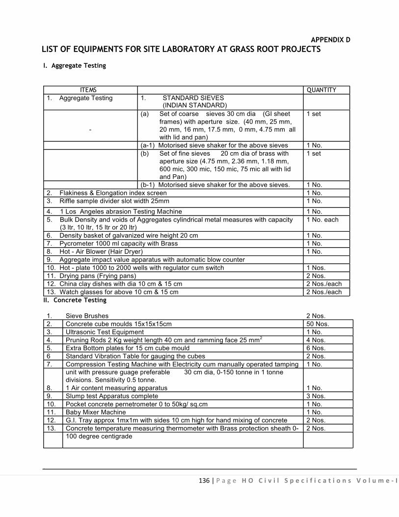
136 | P a g e H O C i v i l S p e c i f i c a t i o n s V o l u m e - I
APPENDIX D
LIST OF EQUIPMENTS FOR SITE LABORATORY AT GRASS ROOT PROJECTS
I. Aggregate Testing
ITEMS QUANTITY
1. Aggregate Testing 1. STANDARD SIEVES (INDIAN STANDARD)
(a) Set of coarse sieves 30 cm dia (GI sheet 1 set frames) with aperture size. (40 mm, 25 mm,
- 20 mm, 16 mm, 17.5 mm, 0 mm, 4.75 mm all with lid and pan)
(a-1) Motorised sieve shaker for the above sieves 1 No. (b) Set of fine sieves 20 cm dia of brass with 1 set
aperture size (4.75 mm, 2.36 mm, 1.18 mm, 600 mic, 300 mic, 150 mic, 75 mic all with lid and Pan)
(b-1) Motorised sieve shaker for the above sieves. 1 No. 2. Flakiness & Elongation index screen 1 No. 3. Riffle sample divider slot width 25mm 1 No. 4. 1 Los Angeles abrasion Testing Machine 1 No. 5. Bulk Density and voids of Aggregates cylindrical metal measures with capacity 1 No. each
(3 ltr, 10 ltr, 15 ltr or 20 ltr) 6. Density basket of galvanized wire height 20 cm 1 No. 7. Pycrometer 1000 ml capacity with Brass 1 No. 8. Hot - Air Blower (Hair Dryer) 1 No. 9. Aggregate impact value apparatus with automatic blow counter 10. Hot - plate 1000 to 2000 wells with regulator cum switch 1 Nos. 11. Drying pans (Frying pans) 2 Nos. 12. China clay dishes with dia 10 cm & 15 cm 2 Nos./each 13. Watch glasses for above 10 cm & 15 cm 2 Nos./each
II. Concrete Testing 1. Sieve Brushes 2 Nos. 2. Concrete cube moulds 15x15x15cm 50 Nos. 3. Ultrasonic Test Equipment 1 No. 4. Pruning Rods 2 Kg weight length 40 cm and ramming face 25 mm2 4 Nos. 5. Extra Bottom plates for 15 cm cube mould 6 Nos. 6 Standard Vibration Table for gauging the cubes 2 Nos. 7. Compression Testing Machine with Electricity cum manually operated tamping 1 No.
unit with pressure guage preferable 30 cm dia, 0-150 tonne in 1 tonne divisions. Sensitivity 0.5 tonne.
8. 1 Air content measuring apparatus 1 No. 9. Slump test Apparatus complete 3 Nos. 10. Pocket concrete pernetrometer 0 to 50kg/ sq.cm 1 No. 11. Baby Mixer Machine 1 No. 12. G.I. Tray approx 1mx1m with sides 10 cm high for hand mixing of concrete 2 Nos. 13. Concrete temperature measuring thermometer with Brass protection sheath 0- 2 Nos.
100 degree centigrade .

137 | P a g e H O C i v i l S p e c i f i c a t i o n s V o l u m e - I
III. Cement Testing 1. Mortar Cube Moulds 7.07x7.07x7.07 cm 10 Nos. 2. Standard sand Grade I,II,III 50 kgs./each 3. Mortar Cube vibrator 1 No. 4. Vicate needle apparatus Computer 1 No. 5. Blaine’s Apparatus 1 No.
IV. Weighing Equipment
1. Physical Balance Capacity 200 gms with weight pony 1 No. 2. Dial type spring balance preferable with zero correction knob capacity 100 kgs 2 Nos.
reading to ½ kg. 3. Counter scale capacity 1 kg and 10 kg 1 No./ each 4. Weighing platform capacity 100 kg 1 No. 5. Iron Weight of 5 kg, 2 kg, 1 kg, 500 gm, 200 gm, 100 gm 2 No./each 6. Brass Weight of 50 gm, 20 gm, 10 gm, 5 gm, 2 gm, 1 gm 2 No./each
V. Water Measuring 5 litres, 2 litres, 1 litre, ½ litre 5 Nos./each VI. Glass and Plastic Ware 1. Measuring cylinder TPX or Poly propylene capacity 100 ml, 500 ml, 250 ml, 2 Nos./each
100 ml 2. Pyrex, corning or Borosil beakers with cover capacity 500 ml, 200 ml, 50 ml 2 Nos./each 3. Wash Bottles capacity 500 ml 2 Nos./each 4. Thermometers 1-100 degree centigrades/ max. and Min/ Dry and wet with 1 No.
table VII. Laboratory Tools
1. Set of box spanner ratchet 2 Nos. 2. Hammer 1lb 2 Nos. 3. Rubber Hammer 2 Nos. 4. Hacksaw with 6 blades 1 Nos. 5. Measuring tape 2 mtr 2 Nos. 6. Depth gauge 20cm 2 Nos. 7. Steel Foot Plate 2 Nos. 8. Vernier Calliper 2 Nos.
VIII. Miscellaneous Items
1. Trowels made from saw blade, 3 mm thick 16x10cm wooden handle 6 Nos. 2. Showels & Spade 6 Nos./each 3. Steel plates 5 mm thick 75x75 cm 2 Nos. 4. Plastic or G.I. Buckets 15 ltr, 10 ltr, 5 ltr 2 Nos. 5. Wheel Barrow 3 Nos. 6. Floor Brushes, hair dusters, scrappers, wire brush, paint brushes, shutter 3 Nos.
steel plat oil, kerosene with stove etc.
.
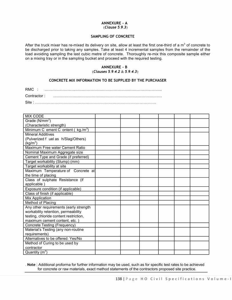
138 | P a g e H O C i v i l S p e c i f i c a t i o n s V o l u m e - I
ANNEXURE - A
(Clause 5.9.3) SAMPLING OF CONCRETE
After the truck mixer has re-mixed its delivery on site, allow at least the first one-third of a m3 of concrete to be discharged prior to taking any samples. Take at least 4 incremental samples from the remainder of the load avoiding sampling the last cubic metre of concrete. Thoroughly re-mix this composite sample either on a mixing tray or in the sampling bucket and proceed with the required testing.
ANNEXURE - B (Clauses 5.9.4.2 & 5.9.4.3)
CONCRETE MIX INFORMATION TO BE SUPPLIED BY THE PURCHASER
RMC : ………………………………………………………………………………..
Contractor : ………………………………………………………………………….
Site : ………………………………………………………………………………….
MIX CODE Grade (N/mm2) (Characteristic strength) Minimum C ement C ontent ( kg./m3) Mineral Additives (Pulverized f uel as h/Slag/Others) (kg/m3) Maximum Free water Cement Ratio Nominal Maximum Aggregate size Cement Type and Grade (if preferred) Target workability (Slump) (mm) Target workability at site Maximum Temperature of Concrete at the time of placing Class of sulphate Resistance (if applicable ) Exposure condition (if applicable) Class of finish (if applicable) Mix Application Method of Placing Any other requirements (early strength workability retention, permeability testing, chloride content restriction, maximum cement content, etc. ) Concrete Testing (Frequency) Material’s Testing (any non-routine requirements) Alternatives to be offered: Yes/No Method of Curing to be used by contractor Quantity (m3)
. Note : Additional proforma for further information may be used, such as for specific test rates to be achieved for concrete or raw materials, exact method statements of the contractors proposed site practice.

139 | P a g e H O C i v i l S p e c i f i c a t i o n s V o l u m e - I
ANNEXURE - C
(Clauses 5.9.6.2 and 5.9.6.3)
CALIBRATION AND WEIGHING EQUIPMENT ACCURACY
C-1. The following limits shall apply to all ready-mixed concrete plants : (a) The accuracy, sensitivity and ar rangement of the weighing dev ices shall be such as to enable the materials to be batched within the following tolerances :
(1) Cement, mineral : Within + 2 percent of the quantity of the constituent Admixtures being measured.
(2) Aggregate, chemical : Within + 3 percent of the quantity of the constituent admixtures and water being measured.
(b) Analogue scales shall have scale increments not exceeding 5 kg. for cement and mineral admixtures, 25 kg. for aggregate and 2 kg. for water. (c) Preset controls shall be calibrated in increments not exceeding 5 kg. for cement and mineral admixtures, 10 kg. for aggregate and 2 kg. for water. (d) F or continuous mixer plants calibration shall be in increments not exceeding 10 kg./m3 for cement and mineral admixtures, 25 kg./m3 for aggregates and 10 l/m3 for water. (e) Digital readous shall have a scale increments not exceeding 2 kg. for cement and mineral admixtures, 10 kg. for aggregate and 10 for water. (f) At the time of installation, or reconditional the accuracy of the indicated mass at any point on the scale shall be within 0.25 percent of the full scale reading. (g) Any other t ime during the masonry operation the accuracy shall be within 0.50 percent of the full scale reading. (h) Chemical Admixture dispensers shall have scale increment for exceeding.
Ranger of sca le in kg/l Sca le increment in Kg/l
0.1 - 0.5 0.01 0.5 - 1.0 0.02 1.0 - 10.0 0.2
more than 10.0 0.4(i)
All weighing and measuring equipment shall be tested and calibrated over its full working range at the following intervals : (1) Mechanical /knife edge systems : At least once every two month
(2) Electrical /load cell systems : At least once every three months
Adequate and identified facilities shall be provided for the application of the test loads. (j) I n the case of batch weighing systems testing and calibration shall be based on the application test loads to the weigh hoppers. (k) Checks on continuous weigh systems shall be based on comparison of p reset quantities w ith those actually produced.
140 | P a g e H O C i v i l S p e c i f i c a t i o n s V o l u m e - I
(l) To achieve the required accuracy of calibration, a minimum of 500 kg. of stamped weights are required, except that for low capacity scale an acceptable limit on the total mass of calibration weight would be 20 percent of the scale capacity.
(m) When calibration of weighing equipment is carried out all personnel involved should be competent and fully trained, the procedures should be fully documented, and special attention should be paid to the health and safety aspects of the procedure.
ANNEXURE - D
DELIVERY TICKET INFORMATION (Clause 5.9.6.5)
D-1 The following information shall be included in the delivery t icket to accompany the load to the purchaser :
(a) Name or number of the ready-mixed concrete depot (b) Serial number of the ticket (c) Date (d) Truck number (e) Name of the Purchaser (f) Name and location of site (g) Grade or mix description of the concrete (h) Specified target workability (i) Minimum cement content (if specified) (j) Type of cement and grade (if specified) (k) Maximum free water-cement ratio (if specified) (l) Nominal maximum size of aggregate (m) Generic Type or name of any chemical and mineral admixtures included. (n) Quantity of concrete in m3
(o) Time of loading (p) Signature of the plant operator (q) A statement warning the purchaser o f the precautions needed to be taken when working w ith cement and wet concrete.
D-2 On site the following information will be added. : (a) Time of arrival on site. (b) Time when discharge was completed. (c) Any water/admixture added by the supplier to meet the specified workability. (d) Any ex tra water /admixture added at the request of the purchaser of the concrete, or his representative, and his signature. (e) Pouring location. (f) Signature of the purchaser or his representative conforming discharge of the load.

141 | P a g e H O C i v i l S p e c i f i c a t i o n s V o l u m e - I
TYPICAL SET UP OF STEEL WALL FORM WORK
Sub Head : R.C.C. (Form Work) Clause : 5.2.3.6
Fig. 5.1A : Single Sided Wall Form (Adjustable)
CLIP
Fig. 5.1B : Double Sided Wall Form All Members are of Steel
Fig. 5.1 : Typical Set Up of Steel Wall Form Work

142 | P a g e H O C i v i l S p e c i f i c a t i o n s V o l u m e - I
WALL FORM
Sub H ead : R .C.C. ( Form W ork) Clause : 5.2.3.6
CLIPS
All Members are of Steel Fig. 5.2 : Adjustable Curved Wall Form (Double Sided)

143 | Page HO Civil Specifications Volume - I
TYPICAL FIXING DETAILS OF WALL TIES
Sub Head : R.C.C. (Form Work) Clause : 5.2.3.6.
WALL THICKNESS47.5 47.5
COILPENETRATION
37.53030
37.5
PLASTIC CONES
COIL T IELENGTH
SOLDIER
WASHER
75 LONG BOLT
Fig. 5.3A : Wall Tie for Two Sided Shuttering
All Members are of Steel
ELEVATION3RD &SUBSEQUENTPOUR
2NDPOUR
1STPOUR
100 STARTER
CHANNELSOULDIER
WALL TIEWALL TUBES
WALL FORM PANELS
CHANNEL SOULDIER 2.5 M LONG
A - ASSEMBLY CLIP
S - SINGLE CLIPB - BRIDGE CLIP
1000
500
500
175
250WALLING
TUBE
175
G
C=175D=1125E=1250F=1375G=2500
50
LAP
C
E
C
D
E
50 L
AP
C
C
Fig. 5.3B : Position of Wall Ties & Walling Tubes (Shuttering for 1st Pour should be properly Strutted by Rakers)
Drawing not to scale All dimensions are in MM
Fig. 5.3 : Typical Fixing Details of Wall Ties
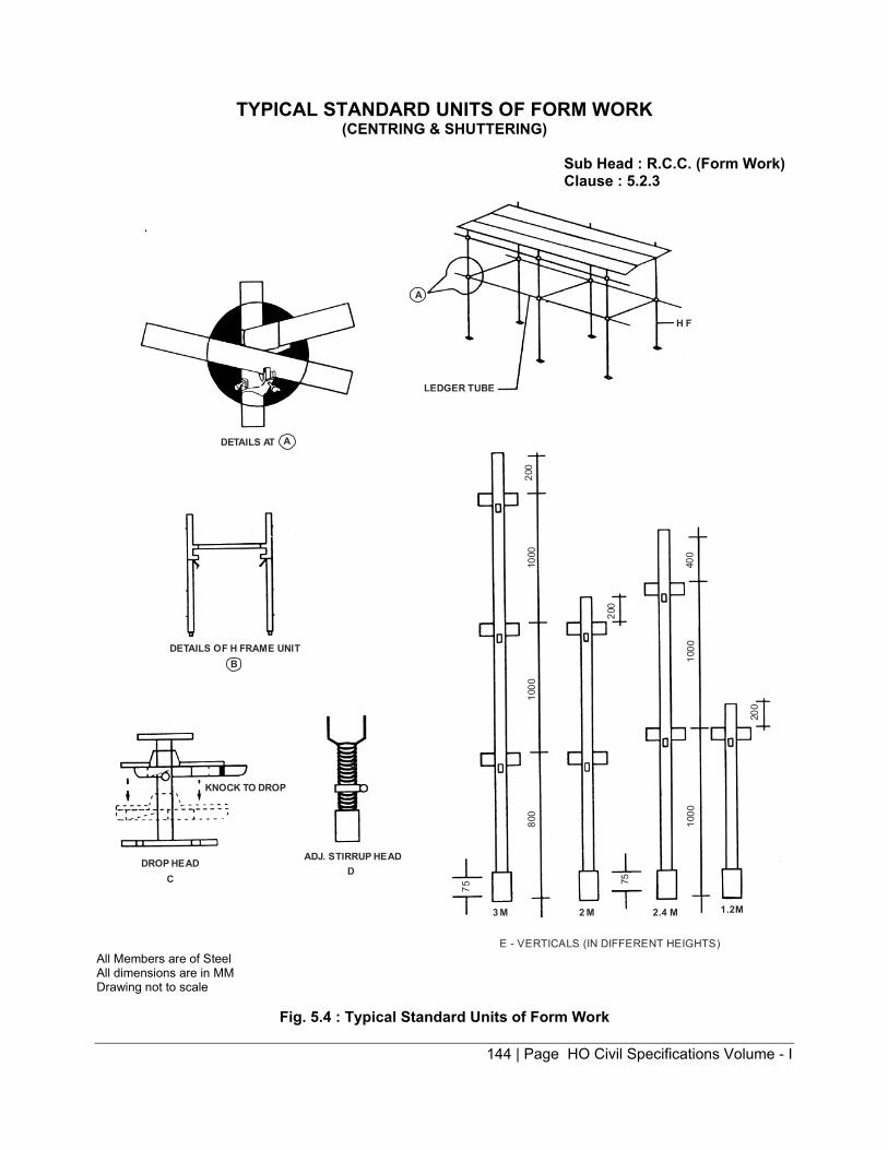
144 | Page HO Civil Specifications Volume - I
TYPICAL STANDARD UNITS OF FORM WORK (CENTRING & SHUTTERING)
Sub Head : R.C.C. (Form Work) Clause : 5.2.3
2.4 M 1.2M
E - VERTICALS (IN DIFFERENT HEIGHTS)
KNOCK TO DROP
DROP HEADC
ADJ. STIRRUP HEAD
D
DETAILS OF H FRAME UNITB
DETAILS AT A
A
H F
LEDGER TUBE
2 M3 M
75
75
800
1000
1000
200
200
1000
1000
400
200
D
All Members are of Steel All dimensions are in MM Drawing not to scale
Fig. 5.4 : Typical Standard Units of Form Work

145 | Page HO Civil Specifications Volume - I
TYPICAL COMPONENTS OF FORM WORK
Sub Head : R.C.C. (Form Work) Clause : 5.2.3.2
ANGLE TRANSOME TUBULAR TRANSOM/LEDGER/HANDRAIL
DIAGONAL
ADJUSTABLE BASEHOP-UP BRACKET ANGLE TIE
A B C
D E F
SCAFFOLD BOARD FIXED BASE PLATE
COLLAR-GRIPSPIGOT LOCK CLIP LOCK
G
I J K
H
Fig. 5.5 : Typical Components of Form Work

146 | Page HO Civil Specifications Volume - I
TYPICAL ARRANGEMENT OF COLUMN FORM WORK
Sub Head : R.C.C. (Form Work) Clause : 5.2.3.2
CORNER ANGLE BRACKET
Fig. 5.6A : Four Sides Adjustable Column Form
CORNER ANGLEBRACKET
EXTERNAL CORNER ANGLE
Fig. 5.6B : Two Sides Adjustable Column Form
TUBESINGLE CLIP
THROUGH TIE/WIRE TIE
Fig. 5.6C : Column Form with Adjustable Shuttering Wall Form Type Panels
All Members are of Steel
Fig. 5.6 : Typical Arrangement of Column Form Work
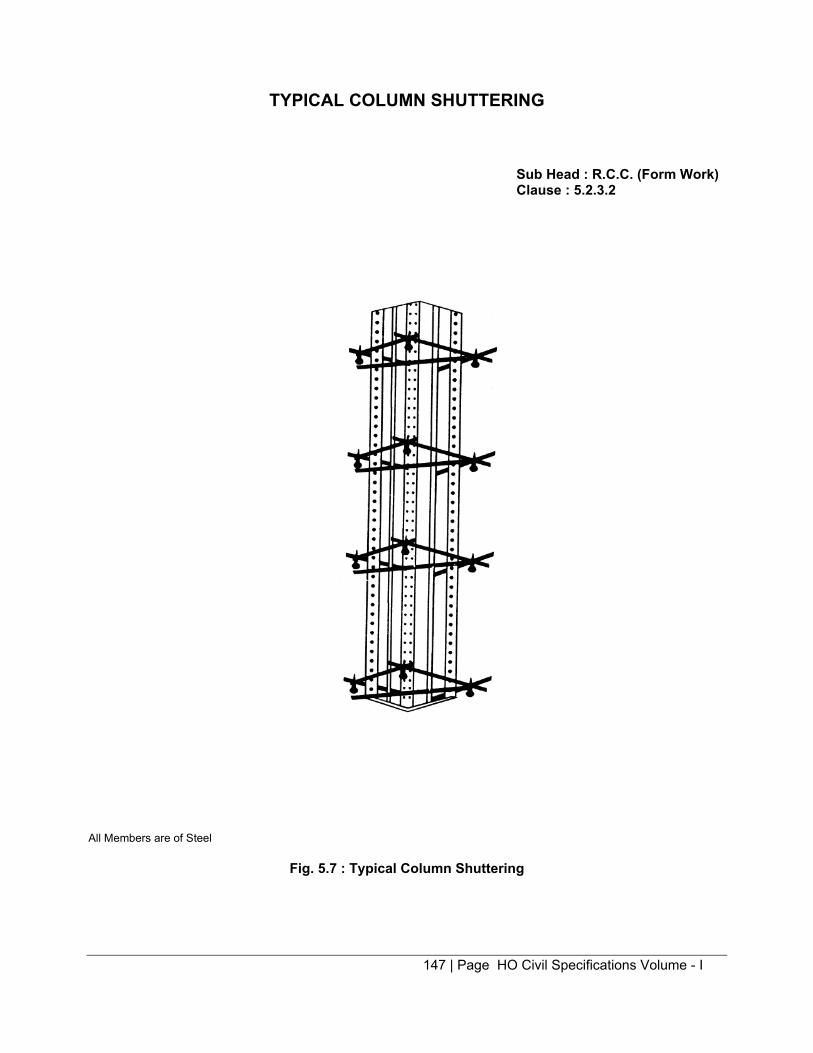
147 | Page HO Civil Specifications Volume - I
TYPICAL COLUMN SHUTTERING
Sub Head : R.C.C. (Form Work) Clause : 5.2.3.2
All Members are of Steel
Fig. 5.7 : Typical Column Shuttering

148 | Page HO Civil Specifications Volume - I
TYPICAL DETAIL OF BEAM HEAD AND STIFFNER
Sub Head : R.C.C. (Form Work) Clause : 5.2.3.3
BEAM HEADPROP
ASSEMBLY OF BEAMHEAD OVER PROP
B
BEAM HEAD A BEAM HEAD C
VARYING WIDTH
38 MM
STIFFNER
STIFFNER10 MM
FLOOR FORMS(OUT OF 14 GAUGE M.S. SHEET) (ADJUSTER
FLOOR FORMS AVAILABLE IN VARIOUS SIZES
E
PLAN OF FLOOR (SLAB) FORMS
D
All Members are of Steel
Fig. 5.8 : Typical Detail of Beam Head and Stiffner

149 | Page HO Civil Specifications Volume - I
TYPICAL DETAILS OF MULTI STAGE SHUTTERING
Sub Head : R.C.C. (Form Work) Clause : 5.2.3.4
BEAMHEAD
PROPS./VERTICALS
HEIGHT < 3.5 M
HEIGHT< 3.5 M
SUSPENDED FLOOR/SLAB TO BE CAST
SHU
TTE
RIN
G
STE
EL
CEN
TRIN
G
All Members are of Steel
Fig. 5.9A : Suspended Floor – Multi Stage Shuttering
(Vertical Section)
TRANSOM
VERTICALS
DIAGONALS
Fig. 5.9B
Fig. 5.9 : Typical Details of Multi-State Shuttering

DETAILS OF EXPANSION JOINTS (IN VARIOUS LOCATIONS)
Sub Head: R.C.C. Clause : 5.4.5
5 Cm
10 MM WIDE JOINTS GROOVE AT R.C.C. -MASONRY JUNCTION
Fig. 5.10 : Expansion Joints in Long Sun Shade
R.C.C. COPING
CRAFT PAPER OR BITUMEN PAINTING
BRICK TILE
BITUMEN FILLER R.C.C. BEAM
A.C. SHEET
BITUMEN PAINTING LIME TERRACING/MUD PHUSKA CEILING P LASTER
R.C.C. SLAB METAL CRADLE
RAWL PLUG & SC REWS WITH OVAL SHAPED SLOT & WASHER
RAWL PLUG & SCREWS
Fig. 5.11 : Details of Raised Type Expansion Joint at Roof
150 | Page HO Civil Specifications Volume - I

151 | Page HO Civil Specifications Volume - I
EXPANSION JOINTS (CONTD.) Sub Head : R.C.C. Clause : 5.4.5
A.C. SHEET
RAWL PLUG & SCREWSRAWL PLUGS & SCREWS WITH OVALSHAPED SLOT & WASHER
R.C.C. BEAMPLASTER
METAL CRADLE FILLED UP WITH BITUMEN FILLER (ABOVE)
R.C.C. SLAB
12 MM GAP FILLED WITH JOINT FILLER
R.C.C. PRECAST TILE 25 MM THICK TO MATCH THE FLOOR FINISH & LAID OVER A COAT OF HOTBITUMEN
Fig. 5.12 : Typical Details of Expansion Joint at Floor
R.C.C. COPING 75 MM THICK
THROATINGC.C. GOLA
BITUMEN FILLER
25 MM GAP
METAL CRADLEBEARING PLASTER WITH A THICK COATOF LIME WASH OR KRAFT PAPER
GROOVE
R.C.C. SLABMUD PHUSKA/LIME CONC.BRICK TILES
BITUMEN PAINTING
Fig. 5.13 : Typical Details of Expansion Joint at Wall & Beam Junction
MASONRY TO BE CONSTRUCTEDAFTER PLACING CANTILEVER SLAB
BRICK WALLPLASTER
SKIRTINGFLOOR FINISH
R.C.C. CANTILEVER SLAB EMBEDDED INMASONRY AT ONE END, FREE AT THEOTHER END
R.C.C. SLABBITUMEN FILLERMETAL CRADLE
25 MM GAPR.C.C. BEAM
PLASTER
MUD PHUSKA
C.C. GOLA
Fig. 5.14 : Typical Details of Expansion Joint at Roof & Floor Junction

152 | Page HO Civil Specifications Volume - I
EXPANSION JOINTS (CONTD.) Sub Head : R.C.C. Clause : 5.4.5
Twin B eams
Twin columns
A
PLAN300
A Twin B eams
150 Coppercradle for beam
External face
Twin columns
Mud fuskalaid to slopeR.C.C. Slab
PlasterR.C.C. Beam
SECTION A – A ON FLOOR
Gap 12DGap 25
FlooringR.C.C.Slab
12 mm open joint infloor staggered fromexpansion joint f illedwith bitumen
SECTION A – A ON ROOF
D25
A. TWIN BEAM WITH TWIN COLUMNS
Fig. 5.15 : Twin Beam with Twin Columns
Unfilled gap
6 mm expansion jointfilled with bitumen filler
(T-Beam changed into rectangular beam to provide intermediate expansion joint)
T-Beam
B. SLAB & T-BEAM CONSTRUCTION OF LONG LENGTH
Bitumen felt12 mm expansion joint filledwith bitumen filler or impregnated f ibre board
R.C.C. Rectangular Beam
Flooring
R.C.C. Slab
Fig. 5.16 : Slab & T-Beam Construction of Long Length
PLAN
12000-13000 12000-13000
KEY PLAN
AAAA
C. LONG VERANDAH SLAB D. LONG WATER-RESERVOIR SLAB
12 12
R.C.C. SlabPlaster 6 mm
Earth filling
SECTION A – A
Bitumen felt
Butt joint in floor & slab
R.C.C. SlabCeiling plaster
Flooring
PART SEC. A–A Fig. 5.17 : Long Verandah Slab Fig. 5.18 : Long Water Reservoir Slab A Hot bitumen painting @ 1.7 k.g/sqm. B Bitumen filler C Rawl plugs & 50 mm screws @ 300 mm c/c D Asbestos sheet 150 mm wide or P.V.C. sheet E Rawl plugs & screws with oval shaped slot & washers @ 300 mm c/c Drawing not to scale F Copper cradle All dimensions are in mm

153 | Page HO Civil Specifications Volume - I
EXPANSION JOINTS (CONTD.) Sub Head : R.C.C. Clause : 5.4.5
R.C.C. COLUMN
25 MM GAP
12 MM GAP
RAWL PLUG & SCREWWITH OVAL SHAPEDSLOT & WASHER
200 MM ASBESTOS CEMENT FLAT SHEET OR ALUMINIUMPLATE OR SIMILAR MATERIALRAWL PLUG & SCREW
INSIDE PLASTER
Fig. 5.19 : Typical Details of Expansion Joint Covering on Outer Face of Columns (Plan)
STEEL OR ALUMINIUM ANGLEFIXED WITH RAWL PLUG &50 MM SCREW @ 300 MM C/C
PLASTER
25 MM G AP
BRICK WORK
12 MM GAP
R.C.C. COLUMN
Fig. 5.20 : Typical Details of Expansion Joints at Corner Column
JOINT FILLER
EXPANDEXBOARD
SEALING COMPOUNDCOLUMN
Fig. 5.21 : Typical Details of Expansion Joint at Isolated Twin Columns
REINFORCEMENT
P.V.C. W ATERSTOP/BAR
JOINT FILLER
DISCONTINUTY IN BOTHCONCRETE & STEEL
Fig. 5.22 : Expansion Joint Subjected to Water Pressure (For water Tanks)
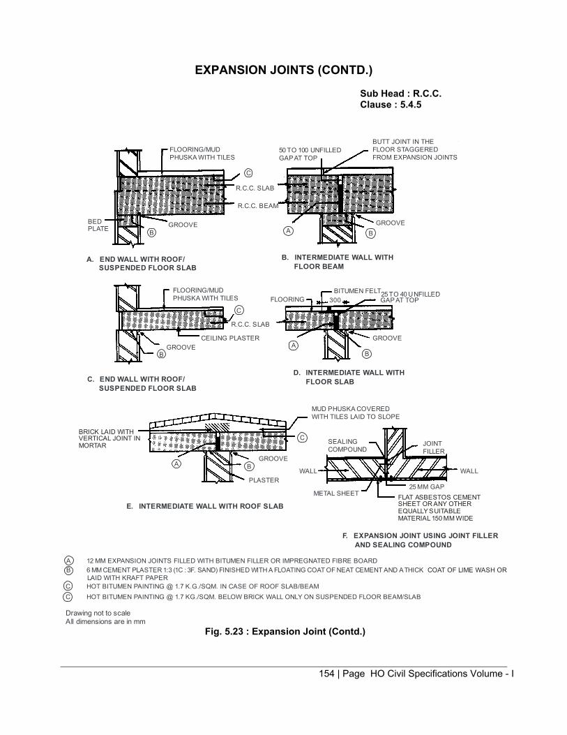
154 | Page HO Civil Specifications Volume - I
EXPANSION JOINTS (CONTD.) Sub Head : R.C.C. Clause : 5.4.5
FLOORING/MUDPHUSKA WITH TILES
C
R.C.C. SLAB
R.C.C. BEAM
GROOVEBEDPLATE B
A. END WALL WITH ROOF/SUSPENDED FLOOR SLAB
FLOORING/MUDPHUSKA WITH TILES
C
R.C.C. SLAB
CEILING PLASTERGROOVE
B
C. END WALL WITH ROOF/SUSPENDED FLOOR SLAB
AGROOVE
B
PLASTER
METAL SHEET25 MM GAP
WALL
JOINTFILLER
WALL
SEALINGCOMPOUND
MUD PHUSKA COVEREDWITH TILES LAID TO SLOPE
D. INTERMEDIATE WALL WITHFLOOR SLAB
BA
GROOVE
300BITUMEN FELT
FLOORING25 TO 40 UNFILLEDGAP AT TOP
BAGROOVE
50 TO 100 UNFILLEDGAP AT TOP
BUTT JOINT IN THEFLOOR STAGGEREDFROM EXPANSION JOINTS
B. INTERMEDIATE WALL WITHFLOOR BEAM
C
E. INTERMEDIATE WALL WITH ROOF SLAB
F. EXPANSION JOINT USING JOINT FILLERAND SEALING COMPOUND
C HOT BITUMEN PAINTING @ 1.7 K.G./SQM. IN CASE OF ROOF SLAB/BEAMC HOT BITUMEN PAINTING @ 1.7 KG./SQM. BELOW BRICK WALL ONLY ON SUSPENDED FLOOR BEAM/SLAB
Drawing not to scaleAll dimensions are in mm
A 12 MM EXPANSION JOINTS FILLED WITH BITUMEN FILLER OR IMPREGNATED FIBRE BOARDB 6 MM CEMENT PLASTER 1:3 (1C : 3F. SAND) FINISHED WITH A FLOATING COAT OF NEAT CEMENT AND A THICK
LAID WITH KRAFT PAPER
BRICK LAID WITH VERTICAL JOINT INMORTAR
FLAT ASBESTOS CEMENTSHEET OR ANY OTHER EQUALLY SUITABLEMATERIAL 150 MM WIDE
COAT OF LIME WASH OR
Fig. 5.23 : Expansion Joint (Contd.)

155 | Page HO Civil Specifications Volume - I
SEISMIC SEPARATION JOINTS Sub Head : R.C.C. Clause : 5.4.5
BITUMENRECTANGULAR BAR
PRE-CAST SLAB/TILES
GAP
RAWL PLUG & SCREW
MASTIC
RAWL PLUG WITH OVALSHAPED SLOT
A.C. SHEET
GAP
RUBBERISED PAD
SHEET METAL FLASHING
FLOORING FLAT BAR SET IN FORMS
CEILING PLASTERR.C.C. SLAB
Fig. 5.24: Seismic Separation at Floor Level
R.C.C. COPING
BRICK TILESTHROATINGC.C. GOLA
GAP
R.C.C. BEAM
GAPRAWL PLUG WITH OVAL SHAPED SLOT
A.C. SHEET
RAWL PLUG & SCREWS
LIME TERRACING/MUD FUSKA
BITUMEN PAINTING
R.C.C. SLAB
CEILING PLASTER
METAL CRADLE
FILLED UP WITH BITUMEN FILLER
Fig. 5.25 : Seismic Separation Joints Detail at Roof
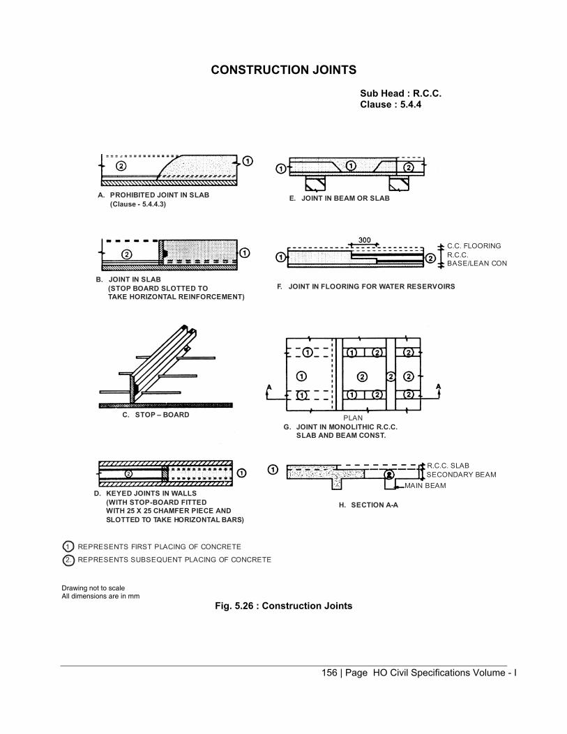
156 | Page HO Civil Specifications Volume - I
CONSTRUCTION JOINTS Sub Head : R.C.C. Clause : 5.4.4
C. STOP – BOARD PLANG. JOINT IN MONOLITHIC R.C.C.
SLAB AND BEAM CONST.
D. KEYED JOINTS IN WALLS(WITH STOP-BOARD FITTEDWITH 25 X 25 CHAMFER PIECE ANDSLOTTED TO TAKE HORIZONTAL BARS)
H. SECTION A-A
R.C.C. SLABSECONDARY BEAM
MAIN BEAM
1 REPRESENTS FIRST PLACING OF CONCRETE
2. REPRESENTS SUBSEQUENT PLACING OF CONCRETE
A. PROHIBITED JOINT IN SLAB(Clause - 5.4.4.3)
E. JOINT IN BEAM OR SLAB
B. JOINT IN SLAB(STOP BOARD SLOTTED TOTAKE HORIZONTAL REINFORCEMENT)
C.C. FLOORINGR.C.C.BASE/LEAN CON
F. JOINT IN FLOORING FOR WATER RESERVOIRS
Drawing not to scale All dimensions are in mm
Fig. 5.26 : Construction Joints

157 | Page HO Civil Specifications Volume - I
ENCASING ROLLED STEEL SECTION Sub Head : R.C.C. Clause : 5.5.2
LAP NOT LESS THAN 100
50
EXPANDED METALOF UNGALVANIZEDWIRE MESH
R.S. JOIST
Fig. 5.27 : Steel Column
5 DIA WIRE HANGER AT 1200 C/C
R.S. JOIST
R.C.C. SLAB
25 25
EXPANDED METAL OR UNGALVANIZED WIRE MESH
Fig. 5.28 : Steel Beam with Slab
Normally Cement Concrete 1 : 2 : 4 (1 Cement : 2 Coarse Sand : 4 Graded Stone Aggregate 12.5 Nominal Size) shall be used. Drawing not to scale All dimensions are in mm

158 | P a g e H O C i v i l S p e c i f i c a t i o n s V o l u m e - I
6.0: Brick Work

159 | P a g e H O C i v i l S p e c i f i c a t i o n s V o l u m e - I
CONTENTS
Clause No. Brief Description Page No.
List of Mandatory Tests 160
List of Bureau of Indian Standard Codes 161
6.0 Terminology 162
6.1 Bricks/ Brick Tiles/ Brick Bats/ 164
6.2 Brick Work 169
6.3 Brick Work in Arches 174
6.4 Half Brick Work 176
6.5 Brick Tile Work 176
6.6 Honey Comb Brick Work 176
6.7 Joining Old Brick Work with New Brick Work 176
6.8 Moulding and Cornices 177
6.9 Brick Work under Water and Foul Conditions 178
6.10 Exposed Brick Work - DELETED 178
6.11 Cavity Wall - DELETED 178
6.12 Gypsum Partition Panels 179
6.13 Brick Edging 179
Appendix A Test for Dimensional Tolerance 180
Appendix B Test for Compressive Strength 181
Appendix C Test for Water Absorption 182
Appendix D Test for Efflorescence 183
Fig. 6.1 Brick Work 184
Fig. 6.2 Brick Pillars 185
Fig. 6.3 & 6.4 Brick Bonds 186
Fig. 6.5 Brick Work in Arches. 188
.

160 | P a g e H O C i v i l S p e c i f i c a t i o n s V o l u m e - I
LIST OF MANDATORY TESTS
Sl. Materia Clause Test Field/ Tes Minimum Q ty. No. laboratory Procedure of material
Test for carrying out test
(i) Bricks/ 6.1.3, Testing of Laboratory Appendix As per Table 6.3 Brick 6.1.4, Bricks/Brick A, B, C & D and 6.4 Tiles 6.1.5 Tiles for of Chapter 6
dimensions, Compressive strength, Water absorption and efflorescence
(ii) Sewer 6.1.4 Dimensions, Laboratory Appendix As per Table 6.3 Bricks Compressive A, B, C & D and 6.4
strength, of Chapter 6 Water absorption and Efflorescence
(iii) Burnt 6.1.5 --do-- -- do -- -- do-- -- do-- clay perforated building bricks
.

161 | P a g e H O C i v i l S p e c i f i c a t i o n s V o l u m e - I
LIST OF BUREAU OF INDIAN STANDARDS CODES
S. No. IS. No. Subject 1. IS 712 Specification for building limes. 2. IS 1077 Common burnt clay building bricks. 3. IS 1200 (Part 3) Method of measurements of brick works 4. IS 2212 Code of practice for brick work. (1st Revision) 5. IS 2222 Specification for burnt clay perforated building bricks. 6. IS 2849 Specification for non load bearing gypsum partition blocks, (Solid
and hollow types) 7. IS 3495 Method of test for burnt clay building bricks. 8. IS 3812 Specification for fly ash for use as pozzolana and admixture. 9. IS 4139 Specification of calcium silicate bricks 10. IS 4885 Specification for sewer brick 11. IS 5454 Methods of sampling of clay building bricks. 12. IS 12894 Pulverized fuel ash lime bricks specification, 13. IS 13757 Specification of burnt clay fly ash bricks.
.

162 | P a g e H O C i v i l S p e c i f i c a t i o n s V o l u m e - I
6.0 BRICK WORK
6.0. TERMINOLOGY
Bond The ar rangement o f t he b ricks in successive c ourses to t ie t he br ick work t ogether both l ongitudinally
and t ransversely. The arrangement is usually designed to ensure that no v ertical joint of one course is exactly over the one in the next course above or below it, and there is greatest possible amount of lap.
Bed Joint Horizontal joint in brick work or masonry.
Closer Any portion of a brick used in constructing a wall, to close up the bond next to the end brick of a
course (See Fig. 6.3).
Coping or Weathering The cover applied over or the geometrical form given to a part of structure to enable i t to shed rain
water.
Corbel A cantilever projecting from the face of a wall to form a bearing (see Fig. 6.1D)
Cornice Horizontal or ornamental feature projecting from the face of a wall (see Fig. 6.1D)
Course A layer of bricks including bed mortar.
Cross joint A joint other than a bed joint normal to the wall face.
Efflorescence A powdery incrustment o f salts left by evaporation. This may be visible on the surface or may be
below surface. In the latter case, this is termed as crypto Efflorescence. Header
A brick laid with its length across the wall.
Indenting The leaving recesses into which future work can be bonded.
Jamb The part of the wall at the side of an opening.
Joint A junction of bricks.
Jointing
The operation of finishing joints as the masonry work proceeds.
Pier A thickened section forming integral part of the wall placed at intervals along the wall primarily to
increase the stiffness of the wall or to carry a v ertical concentrated load. The thickness of a pi er is the over a ll thickness including the thickness of the wall, or w hen bonded into one leaf of a c avity wall the thickness obtained by treating this leaf as an independent wall (see Fig. (6.1A, 6.1B)).

163 | P a g e H O C i v i l S p e c i f i c a t i o n s V o l u m e - I
Pillar
Pillar means a d etached masonry support. This can be rec tangular, c ircular, el liptical etc. In case of rectangular pillar, the breadth shall not exceed three times the thickness and thickness itself shall not exceed more than thrice the length of brick (See Fig. 6.1C).
Quoin An external corner in brick work, the term may also denote the brick used to form the quoin.
Scaffolding A temporary erection of timber or steel work used in the construction, alteration, demolition or repairs of
a bui lding t o support or to at tend of t he hoisting or l owering of w orkmen, t heir t ools a nd m aterials. Scaffoldings are of two types, namely s ingle and doubl e scaffoldings. S ingle scaffolding consists of a row of verticals connected to wall by horizontal supported on and t ied to the structure. Double scaffolding consists of two rows of verticals secured or leashed together w ith hor izontal and di agonal bracings forming essentially a structure independent of the building. It may also connect to the structure at convenient points for the sake of better stability.
Sill A brick work forming the lower boundary of door or window opening (see Fig. 6.1D).
Spandrel The space between the haunches and the road decking of an arch.
Strecher A brick laid with its length in the direction of the wall.
String course A hor izontal c ourse projecting from a wall usually i ntroduced at every floor l evel or w indows or below
parapet for imparting architectural appearance to the s tructure and also keeping of f the rain water. (see Fig. 6.1D).
Templet A pattern of sheet metal used as a guide for setting out specific section and shape.
Toothing Bricks left projecting in alternate courses to bond with future work.
Wall joint A joint parallel to the wall face.
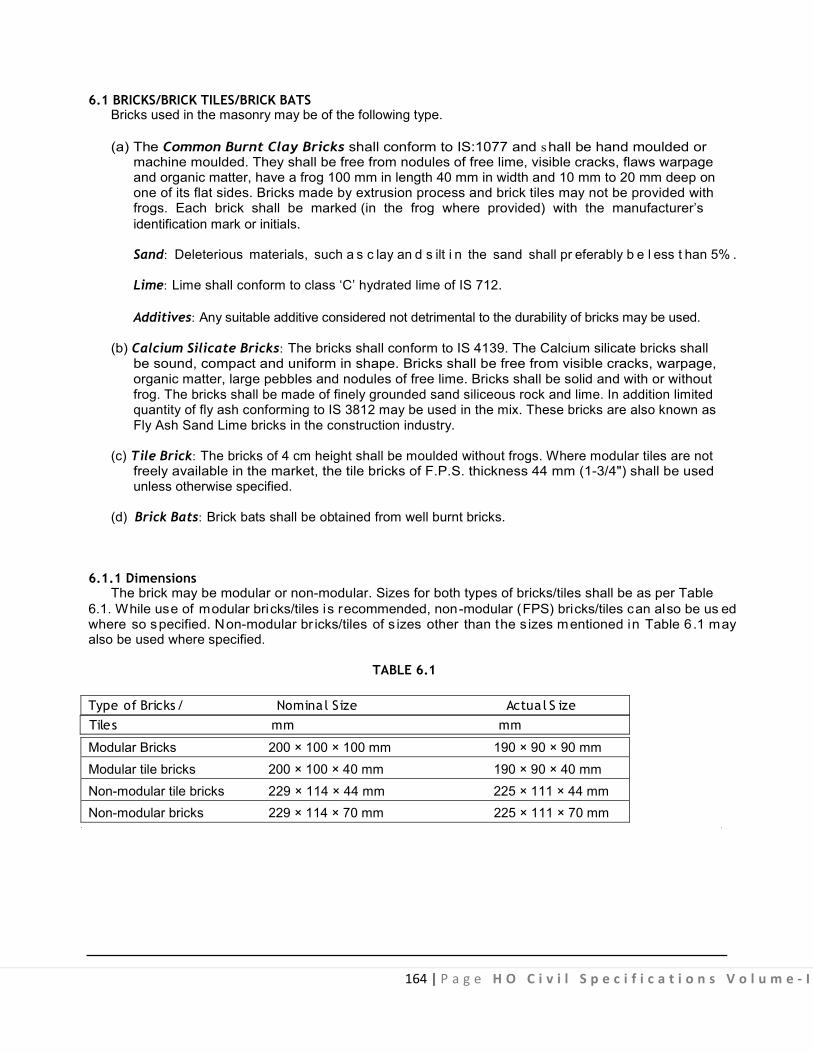
164 | P a g e H O C i v i l S p e c i f i c a t i o n s V o l u m e - I
6.1 BRICKS/BRICK TILES/BRICK BATS Bricks used in the masonry may be of the following type. (a) The Common Burnt Clay Bricks shall conform to IS:1077 and shall be hand moulded or machine moulded. They shall be free from nodules of free lime, visible cracks, flaws warpage and organic matter, have a frog 100 mm in length 40 mm in width and 10 mm to 20 mm deep on one of its flat sides. Bricks made by extrusion process and brick tiles may not be provided with frogs. Each brick shall be marked (in the frog where provided) with the manufacturer’s
identification mark or initials.
Sand: Deleterious materials, such a s c lay an d s ilt i n the sand shall pr eferably b e l ess t han 5% .
Lime: Lime shall conform to class ‘C’ hydrated lime of IS 712.
Additives: Any suitable additive considered not detrimental to the durability of bricks may be used.
(b) Calcium Silicate Bricks: The bricks shall conform to IS 4139. The Calcium silicate bricks shall be sound, compact and uniform in shape. Bricks shall be free from visible cracks, warpage, organic matter, large pebbles and nodules of free lime. Bricks shall be solid and with or without frog. The bricks shall be made of finely grounded sand siliceous rock and lime. In addition limited quantity of fly ash conforming to IS 3812 may be used in the mix. These bricks are also known as Fly Ash Sand Lime bricks in the construction industry.
(c) Tile Brick: The bricks of 4 cm height shall be moulded without frogs. Where modular tiles are not freely available in the market, the tile bricks of F.P.S. thickness 44 mm (1-3/4") shall be used unless otherwise specified.
(d) Brick Bats: Brick bats shall be obtained from well burnt bricks.
6.1.1 Dimensions The brick may be modular or non-modular. Sizes for both types of bricks/tiles shall be as per Table
6.1. While use of modular bricks/tiles is recommended, non-modular (FPS) bricks/tiles can also be us ed where so specified. Non-modular br icks/tiles of s izes other than the s izes mentioned in Table 6.1 may also be used where specified.
TABLE 6.1 Type of Bricks/ Nominal Size Actua l S ize Tiles mm mm
Modular Bricks 200 × 100 × 100 mm 190 × 90 × 90 mm Modular tile bricks 200 × 100 × 40 mm 190 × 90 × 40 mm Non-modular tile bricks 229 × 114 × 44 mm 225 × 111 × 44 mm Non-modular bricks 229 × 114 × 70 mm 225 × 111 × 70 mm

165 | P a g e H O C i v i l S p e c i f i c a t i o n s V o l u m e - I
6.1.2 Classification Bricks/Brick tiles shall be classified on the basis of their minimum compressive strength as given below :
TABLE 6.2
Class Average compress ive strength Des ignation Not less than Less than
N/mm2 (kgf/cm2) N/mm2 (Kgf/cm2) 12.5 (125) 12.5 (125) 15.0 150 10 (100) 10 (100) 12.5 125 7.5 (75) 7.5 (75) 10 100 5 (50) 5 (50) 7.5 75 3.5 (35) 3.5 (35) 5.0 50 The bricks shall have smooth rectangular faces with sharp corner and shall be uniform in colour and
emit clear ringing sound when struck. (Note: Upper l imits specified in Table 6.2 are for calculating the average compressive s trength in
accordance with Appendix B of Chapter 6).
6.1.3 Sampling and Tests Samples of bricks shall be subjected to the following tests : (a) Dimensional tolerance. (b) Water absorption. (c) Efflorescence. (d) Compressive strength.
6.1.3.1 Sampling: For carrying out compressive strength, water absorption, efflorescence and dimensional tests, the samples of br icks shall be taken at random according to the size of lot as given in Table 6.3 below. The sample thus taken shall be stored in a dry place until tests are made. For the purpose of sampling, the following definition shall apply.
(a) Lot: A collection of bricks of same class and size, manufactured under relatively similar conditions of production. For the purpose of sampling a lot shall contain a maximum, of 50,000 bricks. In case a consignment has bricks more than 50,000 of the same classification and size and manufactured under relatively similar conditions of production, it shall be divided into lots of 50,000 bricks or part thereof. (b) Sample : A collection of bricks selected for inspection and/or testing from a lot to reach the decision regarding the acceptance or rejection of the lot.
(c) Defective : A brick failing to meet one or more of the specified requirements.
6.1.3.2 The samples shall be taken as below: (i) Sampling from a Stack: When it is necessary to take a sample from a stack, the stack shall be divided into a number of real or imaginary sections and the required number of bricks drawn from each section. For this purpose bricks in the upper layers of the stack shall be removed to enable units to be sampled from places within the stack.
Note: For other methods of sampling i.e. sampling in motion and sampling from lorries or trucks, IS :5454 may be referred.
Scale of sampling and criteria for conformity for visual and dimensional characteristics:— Visual characteristics: The br icks shall be s elected and i nspected for ascertaining their conformity to the requirements of the relevant specification.

166 | P a g e H O C i v i l S p e c i f i c a t i o n s V o l u m e - I
The number of bricks to be selected from a lot shall depend on the size of lot and shall be in accordance of Col. 1 and 2 of Table 6.3 for v isual characteristics in al l cases and di mensional characteristics if specified for individual bricks.
(ii) Visual Characteristics: All the bricks selected above in accordance with Col. 1 and 2 of Table 6.3 shall be examined for v isual characteristics. I f the number of defective br icks found in the sample is less than or equal to the corresponding number as specified in Col. 3 of Table 6.3 the lot shall be considered as satisfying the requirements of visual characteristics, otherwise the lot shall be deemed as not having met the visual requirements.
(iii) Dimensional Characteristics: The number of bricks to be selected for inspecting the dimensions and tolerance shall be in accordance with Col. 1 and 4 of Table 6.3. These bricks will be divided into groups of 20 bricks at random and each of the group of 20 bricks thus formed will be tested for all the dimensions and tolerances. A lot shall be considered having found meeting the requirements of dimensions and tolerance if none of the groups of bricks inspected fails to meet the specified requirements.
TABLE 6.3 Scale of Sampling and Permissible Number of Defectives for Visual and Dimensional Characteristics
No. of For characteristics For dimens iona l bricks in specified for characteristics for the lot individual b rick group of 20 bricks
No. of Permiss ible No. of bricks to be no.of defective bricks to be selected in the sample selected
(1) (2) (3) (4) 10001—35000 20 1 40 35001—50000 32 2 60 Note: In case the lot contains 10000 or less bricks the sampling shall be as per decision of the
Engineer-in-Charge.
(iv) Scale of Sampling and Criteria for Physical Characteristics: The lot which has been found satisfactory in respect of visual and dimensional requirements shall be next tested for physical characteristics like compressive strength, water absorption, efflorescence as specified in relevant material specification. The bricks for this purpose shall be taken at random from those already selected above. The number of bricks to be selected for each of these characteristics shall be in accordance with relevant columns of Table 6.4.
TABLE 6.4 Scale of Sampling for Physical Characteristics
Lot s ize Sample size for compres - Permiss ible No. Warpage
s ive strength, water of d e fectives Sample Permiss ible abs orption and efflore scence for e fflores cence Size No of defects
(1) (2) (3) (4) (5) 10001—35000 5 0 10 0 35001—50000 10 1 20 1
Note: In case the lot contains 10000 or less bricks, the sampling shall be as per decision of Engineer-in-Charge.
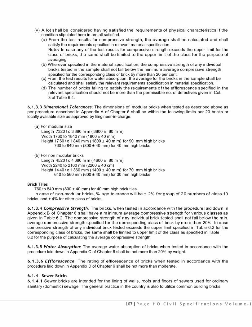
167 | P a g e H O C i v i l S p e c i f i c a t i o n s V o l u m e - I
(v) A lot shall be considered having satisfied the requirements of physical characteristics i f the condition stipulated here in are all satisfied.
(a) From the test results for compressive strength, the average shall be calculated and shall satisfy the requirements specified in relevant material specification.
Note: In case any of the test results for compressive strength exceeds the upper limit for the class of bricks, the same shall be l imited to the upper l imit of the class for the purpose of averaging.
(b) Wherever specified in the material specification, the compressive strength of any individual bricks tested in the sample shall not fall below the minimum average compressive strength specified for the corresponding class of brick by more than 20 per cent. (c) From the test results for water absorption, the average for the bricks in the sample shall be
calculated and shall satisfy the relevant requirements specification in material specification. (d) The number of b ricks failing to satisfy the requirements o f the ef florescence specified in the relevant specification should not be more than the permissible no. of defectives given in Col.
3 of Table 6.4.
6.1.3.3 Dimensional Tolerances: The dimensions of, modular bricks when tested as described above as per procedure described in Appendix A of Chapter 6 shall be within the following limits per 20 bricks or locally available size as approved by Engineer-in-charge.
(a) For modular size Length 7320 t o 3 880 m m ( 3800 ± 80 m m) Width 1760 to 1840 mm (1800 ± 40 mm) Height 17 60 t o 1 840 m m (1800 ± 40 m m) for 90 mm hi gh br icks 760 to 840 mm (800 ± 40 mm) for 40 mm high bricks
(b) For non modular bricks Length 4520 t o 4 680 m m ( 4600 ± 80 m m) Width 2240 to 2160 mm (2200 ± 40 cm) Height 14 40 t o 1 360 m m (1400 ± 40 m m) for 70 mm hi gh br icks 640 to 560 mm (600 ± 40 mm) for 30 mm high bricks
Brick Tiles 760 to 840 mm (800 ± 40 mm) for 40 mm high brick tiles In case of non-modular bricks, % age tolerance will be ± 2% for group of 20 numbers of class 10
bricks, and ± 4% for other class of bricks.
6.1.3.4 Compressive Strength: The bricks, when tested in accordance with the procedure laid down in Appendix B of Chapter 6 shall have a m inimum average compressive s trength for various c lasses as given in Table 6.2. The compressive strength of any individual brick tested shall not fall be low the min. average compressive strength specified for the corresponding c lass of brick by more than 20%. In case compressive strength of any individual brick tested exceeds the upper limit specified in Table 6.2 for the corresponding class of bricks, the same shall be limited to upper limit of the class as specified in Table 6.2 for the purpose of calculating the average compressive strength.
6.1.3.5 Water Absorption: The average water absorption of bricks when tested in accordance with the procedure laid down in Appendix C of Chapter 6 shall be not more than 20% by weight.
6.1.3.6 Efflorescence: The rating of efflorescence of bricks when tested in accordance with the procedure laid down in Appendix D of Chapter 6 shall be not more than moderate.
6.1.4 Sewer Bricks 6.1.4.1 Sewer bricks are intended for the lining of walls, roofs and floors of sewers used for ordinary sanitary (domestic) sewage. The general practice in the country is also to utilize common building bricks
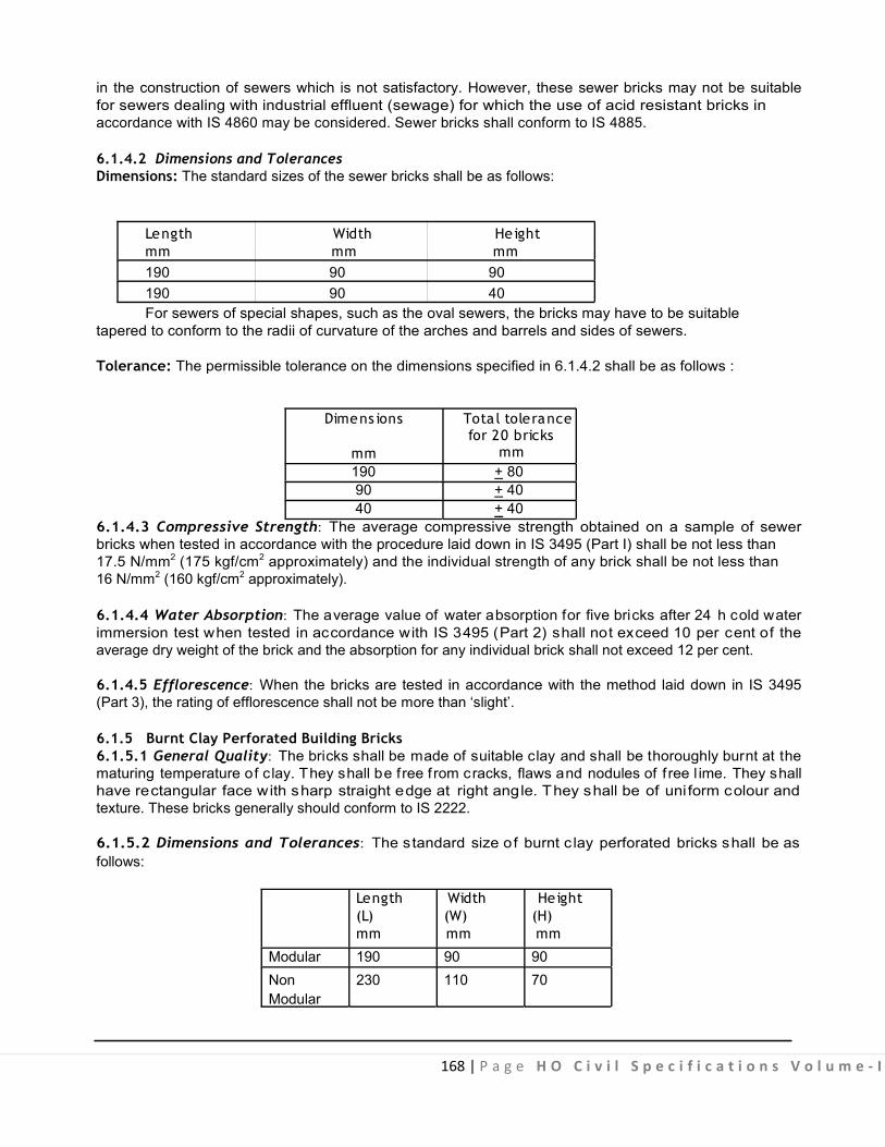
168 | P a g e H O C i v i l S p e c i f i c a t i o n s V o l u m e - I
in the construction of sewers which is not satisfactory. However, these sewer bricks may not be suitable for sewers dealing with industrial effluent (sewage) for which the use of acid resistant bricks in accordance with IS 4860 may be considered. Sewer bricks shall conform to IS 4885. 6.1.4.2 Dimensions and Tolerances Dimensions: The standard sizes of the sewer bricks shall be as follows:
Length Width Height mm mm mm 190 90 90 190 90 40 For sewers of special shapes, such as the oval sewers, the bricks may have to be suitable
tapered to conform to the radii of curvature of the arches and barrels and sides of sewers. Tolerance: The permissible tolerance on the dimensions specified in 6.1.4.2 shall be as follows :
Dimens ions Tota l tolerance
for 20 bricks mm mm 190 + 80 90 + 40 40 + 40
6.1.4.3 Compressive Strength: The average compressive strength obtained on a sample of sewer bricks when tested in accordance with the procedure laid down in IS 3495 (Part I) shall be not less than 17.5 N/mm2 (175 kgf/cm2 approximately) and the individual strength of any brick shall be not less than 16 N/mm2 (160 kgf/cm2 approximately). 6.1.4.4 Water Absorption: The average value of water absorption for five bricks after 24 h cold water immersion test when tested in accordance with IS 3495 (Part 2) shall not exceed 10 per cent of the average dry weight of the brick and the absorption for any individual brick shall not exceed 12 per cent.
6.1.4.5 Efflorescence: When the bricks are tested in accordance with the method laid down in IS 3495 (Part 3), the rating of efflorescence shall not be more than ‘slight’. 6.1.5 Burnt Clay Perforated Building Bricks 6.1.5.1 General Quality: The bricks shall be made of suitable clay and shall be thoroughly burnt at the maturing temperature of clay. They shall be free f rom cracks, flaws and nodules of f ree l ime. They shall have rectangular face with sharp straight edge at right angle. They shall be of uni form colour and texture. These bricks generally should conform to IS 2222.
6.1.5.2 Dimensions and Tolerances: The standard size of burnt c lay perforated bricks shall be as follows:
Length Width Height (L) (W) (H) mm mm mm
Modular 190 90 90 Non 230 110 70 Modular

169 | P a g e H O C i v i l S p e c i f i c a t i o n s V o l u m e - I
The permissible tolerances on the dimensions shall be as follows: Dimens ion Tolerance
mm mm
70, 90 + 4 110, 190 + 7
230 + 10 Note: The tolerances specified above shall apply to measurements on individual bricks.
6.1.5.3 Perforations: The area of perforation shall be between 30% and 45% of the total area of the corresponding face of the bricks.
The pe rforation shall be uni formly di stributed over the surface. In t he case of rectangular perforations, the larger dimension shall be parallel to the longer side of the brick. The shorter side of the perforation shall be less than 20 mm in case of rectangular perforations and less than 25 mm diameter in case of circular perforations.
The area of each perforation shall not exceed 500 mm2.
The thickness of any shell shall not be less then 15 mm and that of any web not less than 10 mm. 6.1.5.4 Compressive Strength: The bri cks when tested in accordance w ith the procedure laid down in IS 3495 (Parts 1 to 4) shall have a minimum average compressive strength of 7 N/ mm2 on net area.
The compressive strength of any i ndividual brick t ested shall not f all bel ow t he minimum compressive strength specified for the corresponding c lass of bri cks. The lot shall t hen be c hecked f or next lower class of brick.
6.1.5.5 Water Absorption: The bricks when tested in accordance with the procedure laid down in IS 3495 (parts 1 to 4): after immersion in cold water for 24 hours water absorption shall not be more than 20 percent by weight.
6.1.5.6 Efflorescence: The bricks when tested in accordance w ith the procedure laid down in IS 3495 (Parts 1 to 4) shall have a rating of efflorescence not more than ‘slight’.
6.1.5.7 Warpage: The bricks when tested in accordance with the procedure laid down in IS 3495 (parts 1 to 4) the average warpage shall not exceed 3%. 6.2 BRICK WORK 6.2.1 Classification
The brick work shall be classified according to the class designation of bricks used. 6.2.2 Mortar
The mortar for the brick work shall be as specified, and conform to accepted s tandards. Lime shall not be used where reinforcement is provided in brick work.
6.2.3 Soaking of Bricks Bricks shall be soaked in water before use for a period for the water to just penetrate the whole
depth of the bricks. Alternatively bricks may be ade quately soaked in s tacks by profusely spraying w ith clean water at regular intervals for a period not less than six hours. The bricks required for masonry work
.
170 | P a g e H O C i v i l S p e c i f i c a t i o n s V o l u m e - I
using mud mortar shall not be s oaked. When the bricks are s oaked they shall be re moved from the tank sufficiently ear ly so that at the t ime of laying they are skin-dry. Such soaked b ricks shall be stacked on a clean place where they are not again spoiled by dirt earth etc.
Note I: The period of soaking may be easily found at site by a field test in which the bricks are soaked in water for different per iods and then broken to find the ex tent of water penetration. The least period that corresponds to complete soaking will be the one to be allowed for in construction work.
Note II : If the bricks are soaked for the required time in water that is frequently changed the soluble salt in the bricks will be leached out, and subsequently efflorescence will be reduced.
6.2.4 Laying 6.2.4.1 Bricks shall be laid in English Bond (Fig. 6.2, 6.3, 6.4) unless otherwise specified. For brick work in half brick w all, b ricks s hall b e l aid i n stretcher b ond. H alf or c ut bricks shall not b e used e xcept as closer where necessary to complete the bond. Closers in such cases, shall be cut to the required s ize and used near the ends of the wall. Header bond shall be used preferably in all courses in curved plan for ensuring better alignment.
Note: Header bond shall also be used in foundation footings un less thickness of walls (width of footing) makes the use of headers impracticable. Where thickness of footing is uni form for a num ber of courses, the top course of footing shall be headers. 6.2.4.2 All loose materials, dirt and set lumps of mortar which may be lying over the surface on which brick work is to be freshly started, shall be removed with a wire brush and surface wetted. Bricks shall be laid on a full bed of mortar, when laying, each brick shall, be properly bedded and set in position by gently pressing with the handle of a trowel. Its inside face shall be buttered with mortar before the next brick is laid and pressed against it. Joints shall be fully f illed and packed with mortar such that no hollow space are left inside the joints. 6.2.4.3 The walls shall be taken up truly in plumb or true to the required batter where specified. All courses shall be laid t ruly horizontal and al l vertical joints shall be t ruly vertical. Vertical joints in the alternate c ourse s hall c ome di rectly one ov er the ot her. Q uoin, J ambs and ot her angl es s hall be properly plumbed as the work proceeds. Care shall be taken to keep the perpends properly aligned within following maximum permissible tolerances :
(a) Deviation from vertical within a storey shall not exceed 6 mm per 3 m height. (b) Deviation in verticality in total height of any wall of building more than one storey in height shall not exceed 12.5 mm. (c) Deviation from position shown on plan of any brick work shall not exceed 12.5 mm. (d) Relative displacement between load bearing wall i n adjacent storeys intended to be vertical alignments shall not exceed 6 mm. (e) A set of tools comprising of wooden straight edge, masonic spirit levels, square, 1 metre rule line and plumb shall be kept on the site of work for every 3 masons for proper check during the progress of work.
6.2.4.4 All quoins shall be accurately constructed and the height of brick courses shall be kept uniform. This will be checked using graduated wooden straight edge or sto rey rod indicating height of ea ch course including thickness of joints. The position of damp proof co urse, w indow si lls, bottom of lintels, top of the wall etc. along the height of the wall shall be m arked on the graduated straight edge or storey rod. Acute and obt use quoins shall be bonded, where practicable in the same way as square quoins. Obtuse quoins shall be formed with squint showing three quar ters br ick on one face and quarter br ick on the other.

171 | P a g e H O C i v i l S p e c i f i c a t i o n s V o l u m e - I
6.2.4.5 The brick work shall be built in uniform layers.
No part of the wall during its construction shall rise more than one metre above the general construction level. Parts of wall left at different levels shall be raked back at an angle of 45 degrees or less with the horizontal. Toothing shall not be permitted as an alternative to raking back. For half brick partition to be keyed into main walls, indents shall be left in the main walls.
6.2.4.6 All pipe fittings and specials, spouts, hold fasts and other f ixtures which are re quired to be bu ilt into the walls shall be embedded, as specified, i n their correct position as the work p roceeds unless otherwise directed by the Engineer-in-Charge.
6.2.4.7 Top courses of all plinths, parapets, steps and top of walls below floor and roof slabs shall be laid with brick on edge, unless specified otherwise. Brick on edge laid in the top courses at corner of walls shall be p roperly radiated and keyed into pos ition to form cut (maru) corners as shown in Fig 6.4. Where bricks cannot be cut to the required shape to form cut (maru) corners, cement concrete 1:2:4 (1 cement : 2 coarse sand : 4 gr aded stone aggregate 20 m m nominal size) equal to thickness of course shall be provided in lieu of cut bricks.
6.2.4.8 Bricks shall be laid with frog (where provided) up. However, when top course is exposed, bricks shall be laid with frog down. For the br icks to be laid with frog down, the frog shall be filled with mortar before placing the brick in position.
6.2.4.9 In case of walls one brick thick and under, one face shall be kept even and in proper plane, while the other face may be slightly rough. In case of walls more than one brick thick, both the faces shall be kept even and in proper plane. 6.2.4.10 To facilitate taking service lines later without excessive cutting of completed work, sleeves (to be paid separately) shall be provided, where specified, while raising the brick work. Such sleeves in external walls shall be sloped down outward so as to avoid passage of water inside.
6.2.4.11 Top of the brickwork in coping and sills in external walls shall be slightly t ilted. Where brick coping and s ills are proj ecting beyond the face of the wall, drip course/throating (to be pai d separately) shall be provided where indicated.
6.2.4.12 Care shall be taken during construction that edges of jambs, sills and projections are not damaged in case of rain. New built work shall be covered with gunny bags or tarpaulin so as to prevent the mortar f rom be ing w ashed a way. D amage, if any, s hall be made g ood to the satisfaction of th e Engineer-in-Charge. 6.2.4.13 Vertical reinforcement in the form of bars (MS or high strength deformed bars or thermo mechanically treated bar s a s per di rection o f E ngineer-in-Charge)), c onsidered nec essary at the c orners and junction of walls and j amb opening doors, windows etc. shall be enc ased with cement mortar not leaner than 1:4 (1 cement : 4 coarse sand), or cement concrete mix as specified. The reinforcement shall be suitably tied, properly embedded in the foundation and at roof level. The dia. of bars shall not be less than 8 m m and c oncrete grade shall be m inimum 1:3:6 (1 cement : 3 c oarse sand : 6 g raded stone aggregate 20 mm nominal size). 6.2.4.14 In retaining walls and the like, where water is likely to accumulate, weep holes, 50 to 75 mm square shall be provided at 2 m vertically and horizontally unless otherwise specified. The lowest weep hole shall be at about 30 cm above the ground level. All weep holes shall be surrounded by loose stones and shall have sufficient fall to drain out the water quickly.
Note : Work of providing loose stone will be payable extra.

172 | P a g e H O C i v i l S p e c i f i c a t i o n s V o l u m e - I
6.2.4.15 Work of cutting chases, wherever required to be made in the walls for housing G.I. pipe, CI pipe or any other fixtures shall be carried out in various locations as per guidelines given below :
(a) Cutting of chases in one brick thick and above load bearing walls. (i) As far as possible services should be planned with the help of vertical chases. Horizontal chases should be avoided. (ii) The depths of vertical chases and hori zontal chases shall not exceed one-third and one-sixth of the thickness of the masonry respectively. (iii) When narrow stretches of masonry (or short length of walls) such as between doors and windows, cannot be avoided they should not be pierced with openings for soil pipes or waste pipes or timber joints, etc. Where there is a possibility of load concentration such narrow lengths of walls shall be checked for stresses and high s trength bricks in mortar or c oncrete walls provided, if required. (iv) H orizontal chases when unavoidable should be located in the upper or lower one-third of height of storey and not more than three chases should be permitted in any stretch of a wall. No c ontinuous hor izontal chase s hall ex ceed o ne m etre in leng th. W here unav oidable, stresses in the affected area should be checked and kept within the permissible limits. (v) Vertical chases should not be closer than 2 m in any stretch of a wall. These shall be kept away from bear ings o f be ams and l intels. If unav oidable, s tresses i n t he a ffected ar ea should be checked and kept within permissible limits. (vi) Masonry directly above a recess, if wider than 30 cm horizontal dimension) should be supported on lintel. Holes in masonry may be provided upto 30 cm w idth and 30 cm height without any lintel. In the case of circular holes in the masonry, no lintel need be provided for holes upto 40 cm in diameter.
(b) Cutting of chases in half brick load bearing walls. No chase shall be permitted in half brick load bearing walls and as such no recessed conduits and concealed pipes shall be provided with half brick thick load bearing walls.
(c) Cutting of chases in half brick non-load bearing wall : Services should be pl anned with the help o f vertical chases. Horizontal c hase should be p rovided only when unavoidable.
6.2.5 Joints The thickness of al l types of joints including brick wall joints and c ross joints shall be s uch that four
course and three joints taken consecutively shall measure as follows: (i) I n case of modular bricks conforming to IS 1077 s pecification for common burnt c lay bui ldings bricks, equal to 39 cm. (ii) In case of non-modular bricks, it shall be equal to 31 cm.
Note : Specified thickness of joints shall be of 1 c m. Deviation f rom the specified thickness of al l joints shall not exceed one-fifth of specified thickness.
6.2.5.1 Finishing of Joints: The face of brick work may be f inished flush or by pointing. In flush finishing either the face joints of the mortar shall be worked out while still green to give a finished surface flush with the face of the brick work or the joints shall be squarely raked out to a depth of 1 cm while the mortar is still green for subsequently plastering. The faces of brick work shall be cleaned with wire brush so as to remove any splashes of mortar during the course of raising the brick work. In pointing, the joints shall be squarely raked out to a depth of 1.5 cm while the mortar is still green and raked joints shall be brushed to remove dust and loose particles and well wetted, and shall be later refilled with mortar to give ruled finish. Some such finishes are ‘flush’, ‘weathered’, ruled, etc.
6.2.6 Curing The brick work shall be c onstantly kept moist on al l faces for a m inimum period of seven days. Brick
work done during the day shall be suitably marked indicating the date on which the work is done so as to keep a watch on the curing period.
173 | P a g e H O C i v i l S p e c i f i c a t i o n s V o l u m e - I
6.2.7 Scaffolding
Scaffolding shall be s trong to withstand al l dead, live and impact loads which are l ikely to come on them. Scaffolding shall be provided to allow easy approach to every part of the work. 6.2.7.1 Single Scaffolding: Where plastering, pointing or any other f inishing has been indicated f or brick work, single scaffolding may be provided, unless otherwise specified. In single scaffolding, one end of the put-logs/pole shall rest in the hole provided in the header course of brick masonry. Not more than one header for each put-log/pole shall be l eft out. Such holes shall not be allowed in the case of pillars, brick work l ess t han o ne m etre i n l ength bet ween t he op enings o r ne ar t he s kew ba cks of a rches or immediately under or near the s tructural member supported by the walls. The holes for put logs/poles shall be made good with brick work and wall finishing as specified. 6.2.7.2 Double Scaffolding: Where the brick work or tile work is to be exposed and not to be finished with plastering etc. double scaffolding having two independent supports, clear of the work, shall be provided.
6.2.8 Measurements
6.2.8.1 Brick work shall be measured in cubic metres unless otherwise specified. Any extra work over the specified dimensions shall be ignored. Dimensions shall be measured correct to the nearest 0.01 m i.e. 1 cm. Areas shall be calculated to the nearest 0.01 sq mtrs and the cubic contents shall be worked out to the nearest 0.01 cubic metres.
6.2.8.2 Brick work shall be measured separately in the following stages: (a) From foundation to floor one level (Plinth level) (b) Plinth (floor one) level to floor two level (c) Between two specified floor levels above floor two level Note : (i) Brick work in parapet walls, mumty, lift machine room and water tanks constructed on the
roof up to 1.2 m height above roof shall be measured together w ith the corresponding work of the f loor next below.
6.2.8.3 No deductions or additions shall be done and no extra payment made for the following :
Note : Where minimum area is de fined for deduction of an opening, void or both, such areas shall refer only to opening or void within the space measured.
(a) Ends of dissimilar materials (that is, joists, beams, l intels, posts, gi rders, raf ters, purl ins, t russes, corbels, steps, etc.); up to 0.1 m2 in section; (b) Opening up to 0.1 m2 in area (see Note); (c) Wall plates, bed plates, and bearing of s labs, Chajjas and the l ike, where thickness does not exceed 10 cm and bearing does not extend over the full thickness of wall; (d) Cement concrete blocks as for hold fasts and holding down bolts; (e) Iron f ixtures, such as wall t ies, pipes upto 300 mm diameter and ho ld fasts for doors and windows; and (f) Chases of section not exceeding 50 cm in girth. (g) Bearing portion of drip course, bearing of moulding and cornice.
Note : In calculating area of an openi ng, any separate l intel or s ills shall be i ncluded with the size of
the opening but end portions of lintel shall be excluded. Extra width of rebated reveals, if any, shall also be excluded.
6.2.8.4 Walls half brick thick and less shall each be measured separately in square metres stating thickness.

174 | P a g e H O C i v i l S p e c i f i c a t i o n s V o l u m e - I
6.2.8.5 Walls beyond half br ick thickness shall be measured in multiples of hal f br ick which shall be deemed to be i nclusive of mortar joints. For the s izes of br icks specified in 6.1.1, hal f br ick thickness shall mean 100 mm for modular and 115 mm for non-modular bricks.
Where fractions of half brick occur due to architectural or other reasons, measurement shall be as follows :
(a) upto 1/4th brick-actual measurements and
(b) exceeding 1/4 brick-full half bricks.
6.2.8.6 String courses, projecting pi lasters, aprons, sills and ot her projections shall be f ully described and measured separately in running metres stating dimensions of each projection.
6.2.8.7 Square or rectangular pillars shall be measured separately in cubic metres in multiple of half brick.
6.2.8.8 Circular pillars shall be measured separately in cubic metres as per actual dimensions.
6.2.8.9 Brick work curved on plan shall be measured like the brick work in straight walls and shall include al l cutting and wastage of bricks, tapered vertical joints and use of extra mortar, i f any. Brick work curved on plan to a mean radius not exceeding six metres shall be m easured separately and extra shall be payable over the rates for brick work in straight walls. Nothing extra shall be payable i f the mean radius of the brick work curved in plan exceeds six metres.
6.2.8.10 Tapered walls shall be m easured net as walls and ex tra payment shall be al lowed for making tapered surface for brick work in walls.
6.2.8.11 Brick work with brick tiles shall be measured and paid for separately.
6.2.9 Rate The r ate s hall i nclude t he cost of materials and labour r equired f or al l t he op erations des cribed a bove
except the vertical reinforcement and i ts encasement in cement mortar or cement concrete. The rate shall also include the following :
(a) Raking out joints or finishing joints flush as the work proceeds; (b) Preparing tops of existing walls and the like for raising further new brick work. (c) Rough cutting and waste for forming gables, splays at eaves and the like. (d) Leaving holes for pipes upto 150 mm dia. and encasing hold fasts etc. (e) Rough cutting and waste for brick work curved in plan and for backing to stone or o ther types of facing. (f) Embedding in ends of beams, joists, slabs, lintels, sills, trusses etc. (g) Bedding wall plates, lintels, sills, roof tiles, corrugated sheets, etc. in or on walls if not covered in respective items and (h) Leaving chases of section not exceeding 50 cm in girth or 350 sq cm in cross-section. (i) Brick on edge courses, cut brick corners, splays reveals, cavity walls, brick works curved on plan to a mean radius exceeding six metres.
6.3 BRICK WORK IN ARCHES (FIG. 6.5)
6.3.0 The detailed specifications for brick work mentioned in 6.2 shall apply, in so far as these are applicable. Arch work shall include masonry for both gauged as well as plain arches. In gauged arches, cut or moulded bricks shall be used. In plain arches, uncut bricks shall be used.
Brick forming skew-backs shall be dr essed or cut so as to gi ve proper radial bearing to the e nd voussiors. Defects in dressing of bricks shall not be covered by extravagant use of mortar, nor shall the use of chips or bats etc. be permitted.

175 | P a g e H O C i v i l S p e c i f i c a t i o n s V o l u m e - I
The bricks of the spandrel wall at their junctions with the extrudes of the arch shall be cut to fit the curvature of the arch. 6.3.1 Circular Arches
These shall be either (a) plain arches, and shall be bu ilt in half br ick concentric r ings with break joints, or (b) gauged arches built with bricks cut or moulded to proper shape. The arch work shall be carried up f rom both ends s imultaneously and keyed in the centre. The bricks shall be f lush with mortar and well pressed into their positions so as to squeeze out a part of their mortar and leave the joints thin and compact. All joints shall be full of mortar and thickness of joints shall not be less than 5 m m nor more than 15 mm.
After the arch is completed, the haunches shall be l oaded by f illing up the spandrels upto the crown level of the arch. Care shall be taken to load the haunches on two sides of the spandrels.
When the arch face is to be pointed (and not plastered), the face bricks shall be cut to proper shape or moulded, so as to have the joints not more than 5 mm thick. These shall be laid with radial joints to the full depth of the arch. The voussoirs shall break joints to the full depth of the arch.
6.3.2 Flat Arches These shall be gauged arches of brick cut or moulded to proper shape. The extrados shall be kept
horizontal and the intrados shall be given slight camber of 1 in 100 of the span. The centre of the arch from which joints shall radiate, shall be determined by the point of the inter-section of t he two lines drawn from the ends of the arch at the springing level and at 60° to horizontal.
In f lat arches, bricks shall be l aid with radial joints to the full depth of arch and v oussoirs breaking joints with each other. The arch work shall be carried up from both ends simultaneously and keyed in the centre. The thickness of the joints shall not exceed 5 mm. Flat arches may be used for the sake of appearance but for purpose of carrying loads of the wall above, these shall be used in conjunction with relieving arches, lintels placed below.
6.3.3 Centring and Shuttering The centring and shuttering for the arch shall be got approved by the Engineer-in-Charge before the
arch work is started. It shall be strong enough to bear the dead load of the arch and the l ive loads that are likely to come upon it during construction, without any appreciable deflections.
The shuttering shall be t ightened with hard wood wedged or sand boxes, so that the same could be eased without jerks being t ransmitted to the arch. The sequence of easing the shuttering shall be g ot approved f rom the Engineer-in-Charge. The shuttering shall be s truck w ithin 48 hours of the completion of the arch but not before 24 hours. This shall be done after the spandrel has been filled in and t he arch loaded.
6.3.4 Measurements The length of the arch shall be measured as the mean of the extrados and intrados of the arch
correct to a cm. The thickness of the arch shall be measured in multiples of the half brick.
The breadth in the direction of the thickness of wall shall be measured as specified.
The cubical contents shall be calculated in cubic metre, correct to two places of decimal.
For arches exceeding 6 m in spans extra payment shall be made on the actual area of the soffit for additional cost of centring including all strutting, bolting, wedging, easing, striking and its removal. 6.3.5 Rate
The rate is inclusive of the cost of the materials and labour required for all the operations described above.

176 | P a g e H O C i v i l S p e c i f i c a t i o n s V o l u m e - I
6.4 HALF BRICK WORK
Brick work in half brick walls shall be done in the same manner as described above in 6.2.4 except that the bricks shall be laid in stretcher bond. When the half brick work is to be reinforced, 2 Nos. M.S. bars of 6 mm dia., shall be embedded in every third course as given in the i tem (the dia of bars shall not exceed 8 mm). These shall be s ecurely anchored at their end where the par titions end. The free ends of the reinforcement shall be keyed into the mortar of the main brick work to which the half brick work is joined. Lime mortar shall not be us ed. O ver l aps i n reinforcement, i f an y s hall not be less than 30 cm.
The mortar interposed between the reinforcement bars and t he brick shall not be l ess than 5 mm. The mortar covering in the direction of joints shall not be less than 15 mm.
6.4.1 Measurements The length and height of the wall shall be measured correct to a cm. The area shall be calculated in
sq.m. where half brick wall is joined to the main walls of one brick or greater thickness and measurements for half brick wall shall be taken for its clear length from the face of the thicker wall.
6.4.2 Rate The rate includes the cost of the materials and labour involved in all the operations described above
except reinforcement which is to be paid for separately.
6.5 BRICK TILE WORK 6.5.0 The work shall be done in the same manner as described in 6.2.4 except that brick tile shall be used instead of bricks. The measurement and rate shall be same as specified under 6.2. 6.6 HONEY COMB BRICK WORK
The honeycomb br ick work shall be done w ith specified c lass of br ick, laid in specified mortar. A ll joints and edges shall be struck flush to give an even surface.
The thickness of the brick honeycomb work shall be half-brick only, unless otherwise specified. Openings shall be equal and alternate with half brick laid with a bearing of 2 cm on either side.
6.6.1 Measurements The length and height shall be measured correct to a c m. Area shall be calculated in square metres
correct to two places of decimal. Honeycomb openings shall not be deducted.
6.6.2 Rate The rate includes the cost of materials and labour involved in all the operations described above.
6.7 JOINING OLD BRICK WORK WITH NEW BRICK WORK 6.7.1 In case the height of the bricks of old as well as new work is same, the old work shall be toothed to the full width of the new wall and to the depth of a quarter of brick in alternate courses. In case the height of the bricks is unequal, then the height of each course of new work shall be made equal to the height of the old work by adjusting thickness of horizontal mortar joints in the new wall. Where necessary, adjustment shall be made equal to thickness of old wall by adjusting the thickness of vertical joints. 6.7.2 For joining new cross wall to old main walls, a number of rectangular recesses of width equal to the thickness of cross wall, three courses in height and half a brick in depth shall be cut in the main
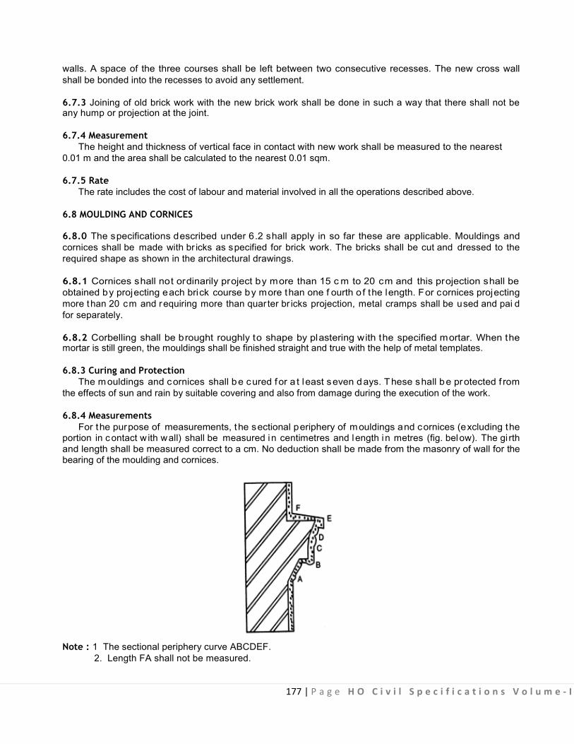
177 | P a g e H O C i v i l S p e c i f i c a t i o n s V o l u m e - I
walls. A space of the three courses shall be left between two consecutive recesses. The new cross wall shall be bonded into the recesses to avoid any settlement. 6.7.3 Joining of old brick work with the new brick work shall be done in such a way that there shall not be any hump or projection at the joint. 6.7.4 Measurement
The height and thickness of vertical face in contact with new work shall be measured to the nearest 0.01 m and the area shall be calculated to the nearest 0.01 sqm.
6.7.5 Rate The rate includes the cost of labour and material involved in all the operations described above.
6.8 MOULDING AND CORNICES
6.8.0 The specifications described under 6.2 shall apply in so far these are applicable. Mouldings and cornices shall be made with br icks as specified for brick work. The bricks shall be cut and dressed to the required shape as shown in the architectural drawings.
6.8.1 Cornices shall not ordinarily project by more than 15 c m to 20 cm and this projection shall be obtained by projecting each brick course by more than one f ourth o f the length. For cornices projecting more than 20 cm and requiring more than quar ter br icks projection, metal cramps shall be used and pai d for separately. 6.8.2 Corbelling shall be brought roughly to shape by plastering with the specified mortar. When the mortar is still green, the mouldings shall be finished straight and true with the help of metal templates. 6.8.3 Curing and Protection
The mouldings and cornices shall be cured for a t least seven days. These shall be protected f rom the effects of sun and rain by suitable covering and also from damage during the execution of the work.
6.8.4 Measurements For the purpose of measurements, the sectional periphery of mouldings and cornices (excluding the
portion in c ontact w ith wall) shall be measured in centimetres and length i n metres (fig. below). The gi rth and length shall be measured correct to a cm. No deduction shall be made from the masonry of wall for the bearing of the moulding and cornices.
Note : 1 The sectional periphery curve ABCDEF. 2. Length FA shall not be measured.
178 | P a g e H O C i v i l S p e c i f i c a t i o n s V o l u m e - I
6.8.5 Rate
The rate includes the cost of materials and labour involved in all the operations described above.
6.9 BRICK WORK UNDER WATER OR FOUL CONDITIONS Brick Work under following conditions :
(i) Work in or under w ater/or l iquid mud; (ii) Work in or under foul positions Shall be measured separately for payment of extra rate over and above the quantity measured
and paid under para 6.2.8.
6.10 EXPOSED BRICK WORK - DELETED
6.11 CAVITY WALL - DELETED

179 | P a g e H O C i v i l S p e c i f i c a t i o n s V o l u m e - I
6.12 GYPSUM PARTITION PANELS
6.12.1 The material shall conform to IS:2849.
6.12.2 Dimensions As per the item nomenclature.
6.12.3 Laying (i) Panels are stored in a dry place and water should not come in contact with panels during or after
construction. If the panels get wet, they should be dried before use. (ii) The floor should be perfectly level before laying the first course. All panels must be properly
aligned to the plumb. Successive layer of panels must be al ternatively s taggered so that vertical joints are not in the same line.
(iii) The recommended quantity of Gypsum Bonding Plaster must be used for joints and filling the grooves made for conduits, pipelines, etc. Excess Bonding Plaster must be scooped and
removed, so that the joints and the places where the grooves are filled in are flush and even. (iv) The walls should be dry and sanding done properly especially at joints before the primer is applied so that the surface is even and joints will not be visible after painting. Avoid chasing with chisel and hammer. Use electrical saw or grooving tools for conduiting etc. (v) The recommended span of walls is maximum 6 meters and maximum height is 4.5 meters. (vi) Gypsum panel can easily be cut with coarse tooth hand saw, electric jigsaw, etc. The panels can be cut, sawn, drilled, milled or dowelled on the job. For concealed piping and conduit, the depth of groove should not exceed 50 mm. Hammer and chisel techniques to form chases must be avoided. (vii) Sanding: This application is to make the surface level without undulations. To make the gypsum wall surface level (in particular at joints, where there is excess bonding plaster), do sanding with sand paper at joints and other places, wherever you find uneven surface, otherwise joints will be visible after painting. It is important to sand all joints uniformly. (viii) Primer Application: The purpose of the primer is to give a better adhesion to the paint and also to reduce consumption of paint on the wall. Water thinable primers shall be used only.
6.12.4 Measurements The length and height shall be measured correct to a c m. Area shall be calculated in square meters
correct to two place of decimal. No deduction shall be made for ducts, opening made f rom the standard size of panel.
6.12.5 Rate The rate shall include the cost of materials and labour involved in all the operations described above.
6.13 BRICK EDGING 6.13.1 The edging shall be of bricks of class specified in the item. The specifications of bricks shall be as described in 6.1. Trenches of required depth and width shall first be made along the edge of the plinth protection to receive the bricks for edging. The bed of trenches shall be compacted to a firm and even surface. The brick shall be laid true to line in cement mortar 1:4 (1 cement: 4 fine sand) with length parallel and butting the plinth protection. The top face of the brick edging shall be in one level to conform to the finished le vel of th e pli nth pr otection adjacent to the ed ging. A fter t he co ncreting is do ne, no portion of t he brick edging shall project above the adjacent concrete surface. Cement mortar shall conform to the specification described in chapter 3.0.
6.13.2 Measurements The brick edging shall be measured in running metere correct a cm.
6.13.3 Rate Rate shall include the cost of materials and labour involved in all operations.

180 | P a g e H O C i v i l S p e c i f i c a t i o n s V o l u m e - I
APPENDIX A
TEST FOR DIMENSIONAL TOLERANCE (Clause 6.1.3.3)
A -1. Sampling As per para 6.1.3.1 and 6.1.3.2.
A -2. Procedure All the bl isters, loose particles of c lay and small projections shall be removed f rom the surface of
bricks. Each specimen of 20 bricks shall then be arranged upon a level surface successively as indicated in Fig. A, B and C of para A -4 below in contact with each other and in straight line. The overall length of the assembled bricks (20 Nos) shall be measured with a steel tape sufficiently long to measure the whole row at one stretch.
A-3. Tolerance The actual dimensions of bricks when tested as described in A-2 shall be within the following limits per
20 bricks.
Modular Bricks Length 3720 to 3880 mm (3800 ± 80 mm) Width 1760 to 1840 mm (1800 ± 40 mm) Height 1760 to 1840 mm (1800 ± 40 mm) for 90 mm high brick
760 to 840 mm (800 ± 40 mm) for 40 mm high brick
Non-Modular Bricks For class 10 Length (4520 to 4680) mm (4600 ± 80 mm) Width (2240 to 2160) mm (2200 ± 40 mm) Height (1440 to 1360) mm (1400 ± 40 mm) for 70 mm high bricks
(640 to 560) mm (600 ± 40 mm) for 30 mm high bricks
For other classes Length (4320 to 4680) mm Width (2130 to 2310) mm Height (1340 to 1460) mm for 70 mm high bricks
(840 to 920) mm for 44 mm high bricks A-4. Criteria for Conformity
A lot shall be considered conforming to the requirements of d imensions and tolerances if a ll the groups of bricks are tested to meet the specified requirements.
1 to 2 CM
4 CM
'A' Measurement of Length 10 CM
'B' Measurement of Width 'C' Measurement of Height

181 | P a g e H O C i v i l S p e c i f i c a t i o n s V o l u m e - I
APPENDIX B
TEST FOR COMPRESSIVE STRENGTH (Clause 6.1.3.4)
B-1. Specimen Five whole bricks shall be taken from the samples as specimens for this test. Length and w idth of
each specimen shall be measured correct to 1 mm. B-2. Apparatus
The app aratus consists o f compression testing machine, t he c ompression plate o f which s hall have a ball seating in the form of portion of a s phere the centre of which shall coincide with the centre of the plate.
B-3. Procedure (a) Pre-conditioning: The specimen shall be immersed in the water for 24 hours at 25º to 29ºC. Any surplus moisture shall be allowed to drain at room temperature. The frog of the bricks should be filled flush with mortar 1:3 (1 cement : 3 clean coarse sand of grade 3 mm and down) and shall be kept under damp jute bags for 24 hours, after that these shall be immersed in clean water for three days.
After removal from water, the bricks shall be wiped out of any traces of moisture. (b) Actual Testing: Specimen shall be placed with flat faces horizontal and mortar filled face upward between three 3 ply plywood sheets each of thickness 3 mm and carefully centred between plates of the testing machine. Plaster of Paris can also be used in place of plywood sheets to ensure a uniform surface.
Load shall be appl ied carefully ax ially at uni form rate of 14 N/mm2 per minute t ill the failure of the specimen occurs.
B-4. Reporting the Test Results The compressive strength of each specimen shall be calculated in N/mm2 as under :
Maximum load at failure (in N) Compressive Strength = ———————————————— Area of Specimen (in sq mm)
In case the compressive strength of any individual brick tested exceeds the upper l imit of the average compressive s trength specified f or the corresponding class of brick, the same shall be limited to the upper l imit of the c lass specified in 6.1.2 for the purpose of calculating the average compressive strength. Compressive s trength of al l the individual bricks comprising the sample shall be averaged and reported.
B-5. Criteria for Conformity A lot shall be considered having satisfied the requirements of average compressive strength if the
average compressive s trength specified in 6.1.2 for the corresponding c lass of brick tested is not below the minimum average compressive strength specified for the corresponding class of bricks by more than 20 per cent.

182 | P a g e H O C i v i l S p e c i f i c a t i o n s V o l u m e - I
APPENDIX C
TEST FOR WATER ABSORPTION (Clause 6.1.3.5)
C-1. No. of Specimen Five whole bricks shall be taken from samples as specimen for this test.
C-2. Apparatus A balance required for this test shall be sensitive to weigh 0.1 percent of the weight of the specimen.
C-3. Procedure (a) Pre-conditioning: The specimen shall be allowed to dry in a ventilated oven at a 110°C to 115°C till it attains a substantially constant weight. If the specimen is known to be relatively dry, this would be accomplished in 48 hours, if the specimen is wet, several additional hours may be required to attain a constant weight. It shall be allowed to cool at room temperature. In a ventilated room, properly separated bricks will require four hours for cooling, unless electric fan passes air over them continuously in which case two hours may suffice.
The cooled specimen shall be weigh (W1) a warm specimen shall not be used for this purpose.
(b) Actua l Te sting: Specimen shall be completely dried before immersion in the water. It shall be kept in clean water at a temperature of 27°C ± 2°C for 24 hours. Specimen shall be wiped out of the traces of water with a damp cloth after removing from the water and then shall be weighed within three minutes after removing from water (W2).
C-4. Reporting the Test Results The water absorption of each specimen shall be calculated as follows and the average of f ive tests
shall be reported.
⎛W − W ⎞ Water Absorption =
C-5. Criteria for Conformity
2 1 ×100
W 1
A lot shall be considered having satisfied the requirements of water absorption if the average water absorption is not more than 20% by weight.
183 | P a g e H O C i v i l S p e c i f i c a t i o n s V o l u m e - I
APPENDIX D
TEST FOR EFFLORESCENCE (Clause 6.1.3.6)
D-1. No. of Specimen Five whole bricks shall be taken as specimen for this test.
D-2. Apparatus Apparatus required for this test shall be a shallow flat bottom dish containing distilled water.
D-3. Procedure (actual testing) The brick shall be placed vertically in the dish with 2.5 cm immersed in the water. The room shall be
warm (18ºC to 30ºC) and w ell ventilated. The br icks should not be removed u ntil it abs orbs whole water. When the whole water is absorbed and the brick appears to be dry, place a similar quantity of water in that dish and allow it to evaporate as before. The brick shall be examined after the second evaporation.
D-4. Reporting the Test Results The rating t o efflorescence i n a scending order shall b e re ported as ‘NIL’, ‘ SLIGHT’, ‘MODERATE’,
‘HEAVY’ or ‘SERIOUS’ in accordance with the following :
(a) NIL: When there is no perceptible deposit of efflorescence.
(b) SLIGHT: When not more than 10 per cent of the area of the brick is covered with a thin deposit of salts.
(c) MODERATE: When there is heavier deposit and covering upto 50% of the area of the br ick surface but unaccompanied by powdering or flaking of the surface.
(d) HEAVY: When there is a heav y deposit of salts covering 50% or more of the brick surface but unaccompanied by powdering or flaking of the surface.
(e) SERIOUS : When there i s heavy deposit of salts, accompanied powdering and/or f laking of t he surface and tending to increase in the repeated wetting of the specimen.
D-5. Criteria for Conformity A lot be considered having satisfied the requirements of efflorescence if for 4 out of the specimen of
5 bricks, the rating of efflorescence is not beyond “Moderate”.
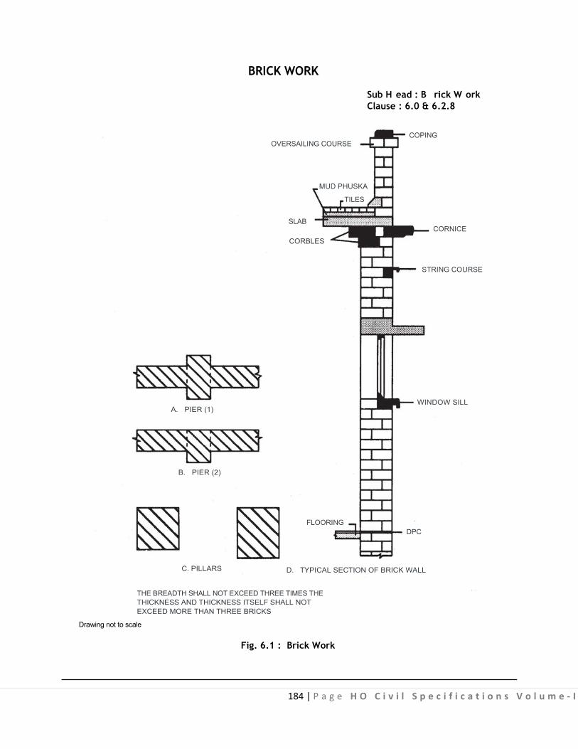
184 | P a g e H O C i v i l S p e c i f i c a t i o n s V o l u m e - I
BRICK WORK
Sub H ead : B rick W ork Clause : 6.0 & 6.2.8
COPING
OVERSAILING COURSE MUD PHUSKA
TILES
SLAB CORNICE
CORBLES
STRING COURSE
WINDOW SILL A. PIER (1)
B. PIER (2)
FLOORING DPC
C. PILLARS D. TYPICAL SECTION OF BRICK WALL
THE BREADTH SHALL NOT EXCEED THREE TIMES THE THICKNESS AND THICKNESS ITSELF SHALL NOT EXCEED MORE THAN THREE BRICKS
Drawing not to scale
Fig. 6.1 : Brick Work

185 | Page HO Civil Specifications Volume - I
BRICK PILLARS Sub Head : Brick Work Clause : 6.2.4.1
EVEN COURSESODD COURSES
1 X 1½ BRICK
1 X 2 BRICK
1 X 2 BRICK½
1 X 2 BRICK ½
2 X 2 BRICK
1 X 1 BRICK ½ ½
150 100
200100 50
50 100 200
150 200 150100
50 100 200
150100
100
100
200
200
100 20
0
100
300
100
50
400
30015
0
100
Drawing not to scale All dimensions are in mm
Fig. 6.2 : English Bond

186 | Page HO Civil Specifications Volume - I
BRICK BONDS Sub Head : Brick Work Clause : 6.2.4.1
ODD COURSES EVEN COURSES
1 BRICK WALL200 100
Q U E E NCLOSER
1½ BRICK WALL
200200
2 BRICK WALL
200
200
200
100
200
100
50
100 100200
Drawing not to scale All dimensions are in mm
Fig. 6.3 : English Bond
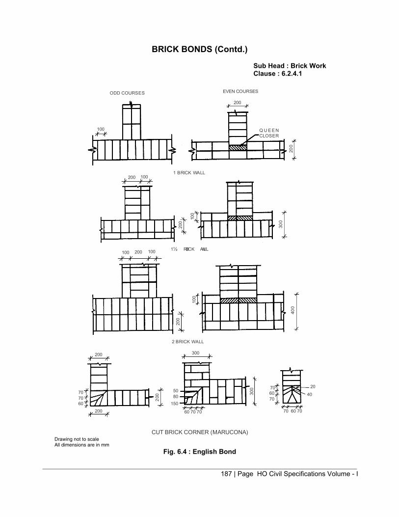
187 | Page HO Civil Specifications Volume - I
BRICK BONDS (Contd.) Sub Head : Brick Work Clause : 6.2.4.1
ODD COURSES EVEN COURSES
200
100
1002001 BRICK WALL
1 BRICK WALL½
Q U E E NCLOSER
200
200
200 100
200 300
200
100
300
100
400
707060
200
200 60 70 70
5080
150
706070
70 60 70
300
2 BRICK WALL
CUT BRICK CORNER (MARUCONA)
20
40
100
Drawing not to scale All dimensions are in mm
Fig. 6.4 : English Bond
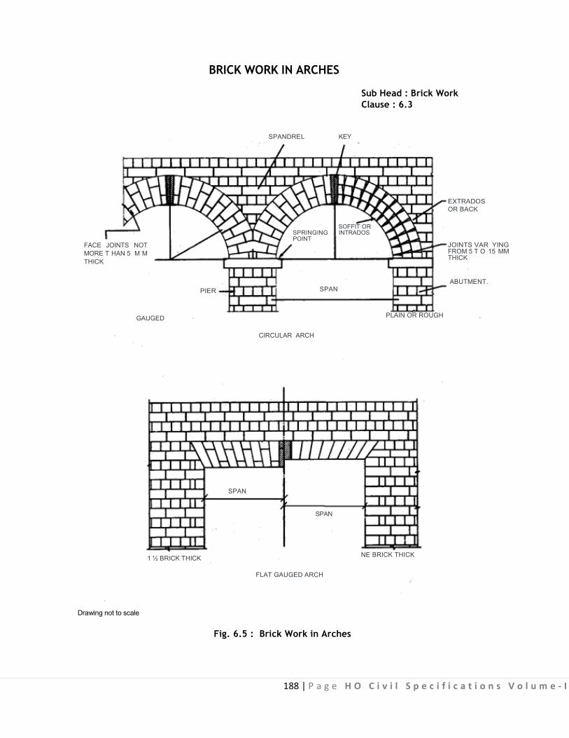
188 | P a g e H O C i v i l S p e c i f i c a t i o n s V o l u m e - I
BRICK WORK IN ARCHES
Sub Head : Brick Work Clause : 6.3
FACE JOINTS NOT MORE T HAN 5 M M THICK
PIER
GAUGED SPAN
1 ½ BRICK THICK
Drawing not to scale
SPANDREL KEY
EXTRADOS OR BACK
SOFFIT OR
SPRINGING INTRADOS POINT
JOINTS VAR YING FROM 5 T O 15 MM THICK
ABUTMENT. SPAN
PLAIN OR ROUGH
CIRCULAR ARCH
SPAN
NE BRICK THICK
FLAT GAUGED ARCH
Fig. 6.5 : Brick Work in Arches

189 | P a g e H O C i v i l S p e c i f i c a t i o n s V o l u m e - I
7.0: Stone Work

190 | P a g e H O C i v i l S p e c i f i c a t i o n s V o l u m e - I
CONTENTS
Clause No. Brief Description Page No.
List of Mandatory Tests 192
List of Bureau of Indian Standard Codes 193
7.0 Terminology 194
7.1 Random Rubble Stone Masonry 196
7.2 Coursed Rubble Masonry - First Sort 201
7.3 Coursed Rubble Masonry - Second Sort 202
7.4 Plain Ashlar Masonry 202
7.5 Punched Ashlar (Ordinary) Masonry 205
7.6 Moulded, Sunk, Carved Ashlar Masonry 205
7.7 Stone Veneering Work 206
7.8 Stone Chajja 208
7.9 Shelves, Coping, Plain, Cornices, String Courses etc. 209
7.10 Stone Jali 209
7.11 Dry Stone Cladding 210
7.12 Structural Steel Frame Work for Dry Stone Cladding 211
7.13 Adjustable Stainless Steel Cramps 212
Fig. 7.1 Stone Work 213
Fig. 7.2 to 7.7 Terminology 214
Fig. 7.8 Random Rubble Masonry 215
Fig. 7.9 Rubble Stone Masonry - Coursed 216
.

191 | P a g e H O C i v i l S p e c i f i c a t i o n s V o l u m e - I
Fig. 7.10 Ashlar Stone Masonry 217
Fig. 7.11 Ashlar Stone Masonry (with Brick Backing) 218
Fig. 7.12 Moulded, Sunk, Carved - Stone Work 219
Fig. 7.13 Stone Work in Arches & Chajjas 220
Fig. 7.14, 7.15 Stone Veneering 221
Fig. 7.16 General Arrangement of Cramps 223
.


194 | P a g e H O C i v i l S p e c i f i c a t i o n s V o l u m e - I
7.0 STONE WORK
7.0 TERMINOLOGY
Ashlar Stone masonry using dressed square stone blocks of given dimensions having faces perpendicular to
each other and laid in courses.
Bed Joint The joint where one stone presses on another for example, a hor izontal joint in a w all or radiating
joint between the voussoirs or arch (See Fig. 7.1 and 7.13)
Block (a) Hollow (Open a nd C losed Cavity) Block: A concrete masonry unit with any one of the external
dimension greater than the corresponding d imension of a br ick and having one or more large holes or cavities which either pass through the block (open cavity) or do ef fectively pass through the block (closed cavity) and having the solid material between 50% and 75% of the total volume of the block calculated from the overall dimensions.
(b) Solid Block: A concrete masonry unit with external dimensions greater than corresponding dimension of a brick and having solid material not less than 75% of the total volume of the block calculated from over all dimension.
Bond An interlocking arrangement of structural units in a wall to ensure stability.
Bond Stone (through Stone) Selected long stone used to hold a wall together transversely (See Fig. 7.8).
Corbel
Stone bonded well into the wall with part of it projecting out of the face of wall to form a bearing surfaces.
Cornice A horizontal moulded projection which crowns or finishes either a wall, any horizontal division of wall, or
any architectural feature (See Fig. 7.1C).
Cramp A small piece of metal or the hardest or toughtest stone procurable, sunk in mortices and fixed
across joints as addi tional ties. The ends o f metal cramps are bent at right an gles and s tone cramps are dovetailed (See Fig. 7.1B).
Course A layer of stones in wall including the bed mortar.
Dowels Dowels a re small sections of metal, s tone or pebbles bedded with m ortar in corresponding m ortice in
bed or side joint or adjacent stones (See Fig. 7.1A). Jamb
The part of the wall at the side of an opening.

195 | P a g e H O C i v i l S p e c i f i c a t i o n s V o l u m e - I
Joggle
A k ey b etween the s tones b y providing a gr oove i n on e s tone t o t ake a c orresponding c oncealed projection in the edges on the other stone (See Fig. 7.1B).
Natural Bed The planes of stratification that occurs in a sedimentary rocks.
Parapet
A solid or pierced guard wall for f lat stone terrace or balcony (or a bridge) or a c urb wall at the lower part of a pitched roof which is exposed to atmosphere on face back and top (See Fig. 7.1C).
Quoin A quoin is the external angle of wall or bu ilding. The term is also applied to stone specially selected
and neatly dressed for forming such angle.
Random Random or irregular size and shapes.
Reveal
The part of the jamb between the frame and the arris.
Rubble Masonry Masonry bu ilt of s tones ei ther i rregular in shapes as quarried or s quared and only hammer dressed
and having comparatively thick joints. As far as possible, stones for rubble masonry shall be angular. Skewback
Sloping surface against which the springing of an arch rests.
Spandrel Space between the haunches below the decking level.
String Course A horizontal band, plain or moulded, usually projecting slightly from the face of wall (See Fig. 7.1C).
Surfacing or Dressing of Stones The stones are dressed to have different surfaces as indicated below.
Template or Bed Block A block of stone or concrete bedded on a wall to distribute the pressure from a concentrated load.
Self Faced Surfaces Surfaces of stone slabs used for roofing, flooring, lintels etc. as obtained from quarry.
Squared Back Surface Means the surface shall be dressed back at right angles to the face of the stone.
Chisel Drafted Margin The dressing done with a drafting chisel in narrow strips of width generally 2 to 5 cm. Chisel drafted
margin shall be punch dressed.
Hammer Dressed Surface A hammer dressed stone shall have no sharp and i rregular corners and shall have a comparatively
even surface so as to fi t well in masonry. Hammer dressed stone is also known as hammer faced, quarry faced and rustic faced. The bushing from the general wall face shall not be more than 40 mm on exposed face and 10 mm on faces to be plastered (Fig. 7.2).
196 | P a g e H O C i v i l S p e c i f i c a t i o n s V o l u m e - I
Rock Faced Surface
A rock faced stone shall have a minimum of 25 mm wide chisel drafted margin at the four edges, all the edges being in the same plane (Fig. 7.3).
Rough Tooled Surface A rough tooled surface shall have a s eries of bands, made by means of a pl ane chisel 4 to 5 cm
wide, more or less parallel to tool marks al l over the surface. These marks may be ei ther horizontal, vertical or at an angle of 45° as directed (Fig. 7.4). The edges and corners shall be square and true. The depth or gap bet ween the surface and s traight edge, held against the surface shall not be m ore than 3 mm (Rough tooled stones are used where fairly regular plane faces are required for masonry work).
Punched Dressed Surface A rough surface is further dressed by means o f punch chisel to show series of parallel ridges. The
depth of gap between the surface and a straight edge held against the surface shall not exceed 3 mm (Fig. 7.5). Punched dressed stones are used where even surfaces are required.
Close Picked Surface A punched s tone is further dressed by means of point chisel so as to obtain a finer surface, ridges or
chisel marks left over being very t iny. The depth of gap bet ween the surface and a s traight edge k ept over the surface shall not exceed 1.5 mm (Fig. 7.6).
Fine Tooled Surface Close picked surface is further dressed so that all the projections are removed and fairly smooth
surface is obtained. The surfaces shall have 3 to 4 lines per centimetre width depending on the degree of hardness of stone and degree of fineness r equired (Fig. 7.7). This type of dr essing is commonly adopted for ashlar work. Polished Surface
Surfaces having a hi gh gloss f inish. Polishing of s tones shall be done by rubbing them with suitable abrasive, wetting the surface where necessary with water. Alternatively polishing of stones shall be done by holding them firmly on t he t op of revolving t able to w hich some abrasive m aterial like sand or carborundum is fed. The final polishing shall be performed by rubber or felt, using oxide of lime (called by trade name as putty powder) as a polishing medium.
Moulded Cut to profile of a moulding with punched dressed surfaces, unless otherwise specified.
7.1 RANDOM RUBBLE STONE MASONRY
7.1.0 Material
7.1.1 Stone The stone shall be o f the type specified such as g ranite, t rap, l imestone, sand stone, quartzite, etc.
and shall be obtained from the quarries, approved by the Engineer-in-Charge. Stone shall be hard, sound, durable and free from weathering decay and defects like cavities, cracks, flaws, sand holes, injurious veins, patches of loose or s oft materials and other s imilar defects that may adversely af fect i ts strength and appearance. As far as possible stones shall be of uniform colour, quality or texture. Generally stone shall not contain crypst crystalline silica or chart, mica and other deleterious materials like iron-oxide organic impurities etc.
Stones with round surface shall not be used.
The compressive strength of common types of stones shall be as per Table 7.1 and the percentage of water a bsorption sh all g enerally n ot ex ceed 5% for sto nes oth er t han s pecified in T able 7. 1. F or laterite this percentage is 12%.

197 | P a g e H O C i v i l S p e c i f i c a t i o n s V o l u m e - I
TABLE 7.1
Type of stone Maximum Water Absorption Minimum Compress ive
Percentage by weight Strength kg./sq.cm. Granite 0.5 1000 Basalt 0.5 400 Lime stone (Slab & Tiles) 0.15 200 Sand stone (Slab & Tiles) 2.5 300 Marble 0.40 500 Quartzite 0.40 800 Laterite (Block) 12 35
Note 1: Test for compressive strength shall be carried out as laid down in IS 1121 (Part I). Note 2: Test for water absorption shall be carried out as laid down in IS 1124.
7.1.2 Size of Stones Normally s tones used should be s mall enough to be lifted and placed by hand. Unless otherwise
indicated, the length of stones for stone masonry shall not exceed three times the height and the breadth on base shall not be greater than three-fourth of the thickness of wall, or not less than 150 mm. The height of stone for rubble masonry may be upto 300 mm.
The selection and grading of stones for rubble masonry is largely done at s ite and the smaller s tones are used in the hearting of wall. 7.1.3 Random Rubble Masonry shall be uncoursed or brought to courses as specified (Fig. 7.8 and 7.9). Uncoursed random rubble masonry shall be c onstructed with stones of s izes as referred to in para 7 .0 and shapes picked up random from the s tones brought from the approved quarry. Stones having sharp corners or round surfaces shall, however, not be used.
7.1.4 Random rubble masonry brought to the course is s imilar to uncoursed random rubble masonry except that the courses are roughly levelled at in tervals varying from 300 mm to 900 mm in h eight according to the size of stones used.
7.1.5 Dressing Each stone shall be hammer dressed on the face, the sides and the beds. Hammer dressing shall
enable the stones to be laid c lose to neighbouring stones such that the bushing in the face shall not project more than 40 mm on the exposed face.
(i) Face stone: At least 25% stones shall be headers tailing into the work at least 2/3rd the thickness of wall in super structure masonry. Such stones shall not be less than 200 sq. cm in cross sections.
(ii) Hearting Stones: The hearting or interior filling of a wall face shall consist of rubble stones not less than 150 mm in any direction, carefully laid, hammered down with a wooden mallet into position and solidly bedded in mortar. The hearting should be laid nearly level with facing and backing.
(iii) Quoin Stone: Quoin stone shall be less than 0.03 cum in volume.
(iv) Jamb stones: The jambs shall not be made with stones specified for quoins except that the stones which were required to be p rovided at 1 metre centre to centre on bot h the exposed faces shall here be provided only on the jamb and the length shall be equal to the thickness of the wall for wall u pto 60 cm and a l ine of head ers s hall be provided fo r w alls thicker than 60 c m as specified for bond.
198 | P a g e H O C i v i l S p e c i f i c a t i o n s V o l u m e - I
7.1.5 (A) Courses The masonry shall be c arried out in regular courses of height not exceeding 50 c m and masonry on
any day w ill not be ra ised more than 60 c m in height when us ing mortars having compressive strength less than 20 kg./sq. cm at 28 days and 100 cm when using mortars exceeding this strength.
7.1.5 (B) Thickness of Joints The joint thickness shall not exceed 30 mm at any point on the face. Chips of the stone and spalls
shall be wedged into seating bed of face s tones to avoid excessive bed t hickness. No pinning shall be allowed to avoid excessive joint thickness.
7.1.6 Mortar The mortar used for joining shall be as specified.
7.1.7 Laying Stone shall be laid on t heir natural bed and s hall be solidly bedded f ull in mortar with c lose joints,
chips of stone spalls be wedged into the work wherever necessary. No dry work or hollow spaces shall be allowed and ev ery stone whether large or small shall be carefully selected t o fit snugly the interstices between the large stones. Masonry shall be built b reaking joints in a ll the three directions. Bond stone and headers shall be properly laid into the work and shall be marked by the contractor w ith white lead paint. The bond stones shall be provided as specified in para 7.1.8.
The masonry work in wall shall be carried up true to plumb or to specified batter.
Random rubble masonry shall be brought to the level courses at plinth, w indow s ills, lintel and roof levels. Levelling shall be done with concrete comprising of one part of the mortar as used for masonry and two parts of graded stone aggregate of 20 mm nominal size.
The masonry in structure shall be carried uniformly. Where the masonry of one part is to be delayed, the work shall be raked back at an angle not steeper than 45°.
7.1.7 (A) Raking out joints All the joints on the faces to be pointed or plastered shall be racked out with racking tool to a depth of
20mm while the mortar is still green.
7.1.8 Bond Stones Though bond s tones shall be provided in walls up to 600 mm thickness, a s et of two or more bond
stones overlapping each other by at least 150 mm shall be prov ided in a l ine from face to back. I n case of highly absorbent types of stones (porous l ime stone and s and stone etc.) the bond s tone shall extend about two-third into the wall, as through stones in such walls a set of two or more bond stones overlapping each other by at least 150 mm shall be provided. Each bond stone or a set of bond stones shall be p rovided for every 0.5 m2 of the wall surface and shall be p rovided at 1.5 m to 1.8 m apart clear in every course.
In case of highly absorbent types of s tones (porous l ime stone and sand s tone etc.) single piece bond stones may give rise to dampness. For al l thicknesses of such walls a set of two or more bond stones overlapping each other by at least 15 cm shall be provided. Length of each such bond stone shall not be less than two-third of the thickness of the wall.
.

199 | P a g e H O C i v i l S p e c i f i c a t i o n s V o l u m e - I
Where bond stones of suitable lengths are not available pre-cast cement concrete block of 1:3:6 mix (1 cement : 3 coarse sand: 6 graded stone aggregate 20 mm nominal size) of cross section not less than 225 square centimetres and length equal to the thickness.
At least one bond s tone or a s et of bond s tones shall be pr ovided at 1.5 m to 1.8 m apart clear in every course. (Bond stones shall be marked suitably with paint as directed by the Engineer-in-Charge).
7.1.9 Quoin and Jamb Stones The quoin and jamb stones shall be of selected stones neatly dressed with hammer or chisel to form the
required angle. Quoin stones shall not be less than 0.01 cum in volume. Height of quoins and jamb stones shall not be less than 15 cm. Quoins shall be laid header and stretcher alternatively.
7.1.10 Joints Stones shall be so laid that all joints are f ully packed with mortar and chips. Face joints shall not be
more than 20 mm thick.
The joints shall be struck flush and finished at the time of laying when plastering or pointing is not to be done. For the surfaces to be plastered or pointed, the joints shall be raked to a minimum depth of 20 mm when the mortar is still green.
7.1.11 Scaffolding Single scaffolding having one set of vertical support shall be allowed. The supports shall be sound
and strong, t ied together by horizontal pieces, over which the scaffolding planks shall be f ixed. The inner end of the horizontal scaffolding member may rest in a hole provided in the masonry. Such holes, however, shall not be allowed in pillars under one metre in width or near the skew back of arches. The holes left in masonry work for supporting scaffolding shall be filled and made good with cement concrete 1 : 3 : 6 (1 cement : 3 coarse sand : 6 stone aggregate 20 mm nominal size).
7.1.12 Curing Masonry work in cement or composite mortar shall be kept constantly moist on all faces for a
minimum period of seven days. In case of masonry with fat lime mortar curing shall commence two days after laying of masonry and shall continue for at least seven days thereafter.
7.1.13 Protection Green work shall be protected from rain by suitable covering. The work shall also be suitably
protected from damage, mortar dropping and rain during construction.
7.1.14 Measurements 7.1.14.1 The length, height and thickness shall be measured correct to a cm. The thickness of wall shall be measured at joints e xcluding the bus hing. O nly s pecified di mensions shall be al lowed; an ything ex tra shall be ignored. The quantity shall be calculated in cubic metre nearest to two places of decimal.
7.1.14.2 The work under the following categories shall be measured separately. (i) From foundation to plinth level (level one) :
(a) work in or under water and or liquid mud, (b) work in or under foul positions.
(i) Above plinth level and upto floor five level. (ii) Above floor five level to every floor/floors or part thereof.
(iv) S tone masonry in parapet shall be measured together w ith the corresponding i tem in the wall o f the storey next below.
7.1.14.3 No deduction shall be made nor extra payment made for the following : (i) E nds of d issimilar materials ( that i s joists, beams, l intels, posts, g irders, rafters purlins, trusses, corbels, steps etc.) upto 0.1 sqm in section.

200 | P a g e H O C i v i l S p e c i f i c a t i o n s V o l u m e - I
.
(ii) Openings each upto 0.1 sqm in area. In calculating the area of openings, any separate lintels or sills shall be included along with the size of opening but the end por tions of the l intels shall be excluded and the extra width of rebated reveals, if any, shall also be excluded. (iii) Wall plates and bed pl ates, and bear ing of chajjas and t he l ike, where the thickness does not exceed 1 0 c m and t he be aring d oes n ot ex tend over t he f ull t hickness of t he wall. Note: The bearing of floor and roof shall be deducted from wall masonry. (iv) Drain holes and r ecesses for cement concrete blocks to embed hold fasts for doors, w indows etc. (v) Building in masonry, i ron fixture, pipes upto 300 m m dia, hold fasts of doors and windows etc. (vi) Forming chases in masonry each upto section of 350 sq cm.
Masonry (excluding fixing brick work) in chimney breasts with smoke of air flues not exceeding 20 sq dm (0. 20 s q m ) i n s ectional area s hall be m easured as s olid and no ex tra payment s hall be m ade f or pargetting and coring such f lues. Where f lues exceed 20 s q dm (0.20 sq m) sectional are a, de duction shall be made for the same and pargetting and coring flues shall be measured in running metres stating size of flues and paid for separately. Aperture for fire place shall not be deducted and no extra payment made for splaying of jambs and throating.
7.1.14.5 Apertures for f ire places shall not be deducted and extra labour shall not be measured for splaying of jambs, throating and making arch to support the opening.
7.1.14.6 Square or Rectangular Pillars: These s hall be measured as walls, but ex tra pa yment s hall be allowed for stone work in square or rectangular pillars over the rate for stone work in walls. Rectangular pillar shall mean a detached masonry support rectangular in section, such that its breadth does not exceed two and a half times the thickness. 7.1.14.7 Circular Pillars (Columns): These shall be measured as per actual dimensions, but extra payment shall be a llowed for stone work in c ircular pillars over the rate for stone work in walls. The diameter as well as length shall be measured correct to a cm.
7.1.14.8 Tapered walls shall be measured net, as per actual dimensions and paid for as other walls. 7.1.14.9 Curved Masonry: Stone masonry curved on plan to a mean radius exceeding 6 metres shall be measured and included with general s tone work. Stone work c ircular on plan to a mean radius not exceeding 6 m etres shall be measured separately and shall include all cuttings and waste and templates. It shall be measured as the mean length of the wall.
7.1.15 Rate The rate shall include the cost of materials and labour required for all the operations described above and
shall include the following : (a) Raking out joints for plastering or poi nting done as a s eparate item, or f inishing flush as the work proceeds. (b) Preparing tops and sides of existing walls for raising and extending. (c) Rough cutting and waste for forming gables cores, skew backs or spandrels of arches, splays at eaves and all rough cutting in the body of walling unless otherwise specified. (d) Bond stones or cement concrete bond blocks. (e) Leading and making holes for pipes etc. (f) Bedding and pointing wall plates, lintels, s ills etc. in or on walls, bedding roof t iles and corrugated sheets in or on walls. (g) Building in ends of joists, beams, lintels etc.

201 | P a g e H O C i v i l S p e c i f i c a t i o n s V o l u m e - I
7.2 COURSED RUBBLE MASONRY - FIRST SORT (FIG. 7.9)
7.2.1 Stone: Shall be as specified in 7.1.1.
7.2.2 Size of Stone: Shall be as specified in 7.1.2.
7.2.3 Dressing Face stones shall be hammer dressed on all beds, and joints so as to give them approximately
rectangular block shape. These shall be s quared on al l joints and beds . The bed j oint shall be r ough chisel dressed for at least 80 mm back from the face, and side joints for at least 40 mm such that no portion of t he dressed surface is more than 6 mm from a straight edge placed on i t The remaining unexposed portion of the stone shall not project beyond the surface of bed and side joint. The bushing on the face shall not project more than 40 mm as an exposed face and 10 mm on a face to be plastered. The hammer dressed stone shall also have a rough tooling for minimum width of 25 mm along the four edges of the face of the stone, when stone work is exposed. 7.2.4 Mortar
The mortar for jointing shall be as specified.
7.2.5 Laying All stones shall be wetted before use. The walls shall be carried up truly plumb or to specified batter. All
courses shall be laid truly ho rizontal and al l v ertical j oints shall be truly v ertical. The he ight of ea ch course shall not be less than 15 cm nor more than 30 cm.
Face stones shall be laid alternate headers and stretchers. No pinning shall be allowed on the face. No face stone shall be less in breadth than its height and at least one third of the stones shall tail into the work for length not less than twice their height.
The hearting or the interior filling of the wall shall consist of stones carefully laid on their proper beds in mortar; chips and spalls of stone being used where necessary to avoid thick beds of joints of mortar and at the same time ensuring that no hollow spaces are left anywhere in the masonry. The chips shall not be used bel ow t he he arting s tone t o bri ng t hese up to t he l evel of f ace s tones. T he us e of c hips s hall be restricted t o t he f illing of i nterstices between t he adjacent stones i n hearting and these shall not exceed 10% of the quantity of stone masonry.
The masonry in a structure shall be carried up uni formly but where breaks are unavoidable, the joints shall be raked back at angle not steeper than 45°. Toothing shall not be allowed.
7.2.6 Bond Stones Shall be as specified in 7.1.8 except that a bond stone or a set of bond stones shall be inserted 1.5 to
1.8 metres apart, in every course. 7.2.7 Quoins
The quoins shall be of the same height as the course in which these occur. These shall be at least 450 mm long and shall be laid stretchers and headers al ternatively. These shall be laid square on the beds, which shall be rough-chisel dressed to a depth of at least 100 mm. In case of exposed work, these stones shall have a m inimum of 25 mm wide chisel drafts at four edges, all the edges being in the same plane. 7.2.8 Joints
All bed joints shall be horizontal and al l side joints vertical. All joints shall be fully packed with mortar, face joints shall not be more than one cm thick.
When plastering or pointing is not required to be done, the joints shall be struck flush and finished at the time of laying. Otherwise, joints shall be raked to a minimum depth of 20 mm by raking tool during the progress of work, when the mortar is still green.

202 | P a g e H O C i v i l S p e c i f i c a t i o n s V o l u m e - I
. 7.2.9 Curing, Scaffolding, Measurements and Rates. Shall be as specified under 7.1.
7.3 COURSED RUBBLE MASONRY - SECOND SORT (FIG. 7.9)
7.3.1 Stone : Shall be as specified in 7.1.1.
7.3.2 Size of Stone : Shall be as specified in 7.1.2.
7.3.3 Dressing: Shall b e as s pecified in 7.2.3 e xcept that no por tion of dr essed surface of joints shall show a d epth of g ap more than 10 mm from a st raight edge placed on it an d use of chips shall not exceed 15 per cent of the quantity of stone masonry.
7.3.4 Mortar The mortar for jointing shall be as specified.
7.3.5 Laying: Shall be as specified in 7.2.5 except that the use of chips shall not exceed 15% of the quantity of stone masonry and s tone, in each course need not be of the same height but not more than two stones shall be used in the height of a course.
7.3.6 Bond Stone, Quoins: Shall be as specified in 7.2.6 and 7.2.7 respectively.
7.3.7 Joints All bed joints shall be horizontal and all side vertical. All joints shall be fully packed with mortar, face
joints shall not be more than 20 mm thick. When plastering or pointing is not required to be done, the joints shall be struck f lush and finished at
the time of laying. Otherwise, the joints shall be raked to a minimum depth of 20 mm by raking tool during progress of work, where the mortar is still green.
7.3.8 Curing, Scaffolding, Measurement and Rates. Shall be as specified under 7.1.
7.4 PLAIN ASHLAR MASONRY (FIG. 7.10) 7.4.1(A) Stone shall be of the type specified. It shall be hard, sound, durable and tough, f ree from cracks, decay and weathering and defects like cavities, cracks, flaws, sand holes, veins, patches of soft or loose m aterials et c. bef ore s tarting t he w ork, t he c ontractor s hall get t he s tones appr oved by Engineer-in-Charge.
7.4.1(B) Kota Stone for Vineering Kota stone shall be of selected quality, hard, sound, dense & homogeneous in texture f ree f rom
cracks, decay, weathering and f laws. They shall be machine cut to requisite s ize and thickness. They shall be of colour indicated in the drawings or as instructed by the Engineer-in-Charge. The stone shall have the top (exposed) f ace pol ished before being brought to s ite unless otherwise specified. Before starting the work, the contractor shall get t he samples of kota stone approved f rom the Engineer-in- Charge.
Dressing : Every stone shall be cut to the required size and shape and fine machine dressed to the full depth so that a straight edge laid along the side of stone shall be in full contact with it. The thickness of the slab after it is dressed shall be 20, 25, 30 or 40 mm as specified in the item. Tolerance of ± 2 mm shall be allowed for the thickness.
7.4.1(C) Red Sand Stone & White Sand Stone Ashlar Masonry The stone shall be red or white as specified in the description of i tem. The stone shall be hard,
sound, tough, free from cracks, decay & weathering. In case of red sand stone, white patches or streaks
.

203 | P a g e H O C i v i l S p e c i f i c a t i o n s V o l u m e - I
shall not be allowed. However scattered spots upto 10 mm diameter will be permitted. Before starting the work the contractor shall get samples of stone approved by the Engineer-in-Charge.
7.4.2 Size of Stone Normally stones used should be small enough to be l ifted and placed by hand. The length of the
stone shall not exceed three times the height and the b readth on base shall no t be greater than three fourth of the thickness of wall nor less than 15 cm. The height of stone may be upto 30 cm.
7.4.3 Dressing Every stone shall be cut to the required size and shape chisel dressed on all beds and joints so as to
be free from waviness and to gi ve truly vertical and horizontal joints. I n ex posed masonry, t he faces that are to remain exposed in the final position and the adjoining faces to a depth of 6 mm shall be the fine chisel dressed so that when checked with 60 cm straight edge, no point varies from it by more than 1 mm. The top and bottom faces that are to form the bed joints shall be chisel dressed so that variation from 60 cm straight edge at no point exceeds 3 mm. Faces which are to form the vertical joints should be chisel dr essed s o t hat v ariation at any poi nt w ith 60 c m s traight edge do es not ex ceed 6 m m. A ny vertical face that is to come against backing of masonry shall be dressed such that variation f rom straight edge does not exceed 10 mm. All angles and edges that are to remain exposed in the final position shall be true, square and free from chippings.
A sample of dressed stone shall be prepare d for approv al of Engineer-in-Charge. I t shall be k ept at the worksite as a sample after being approved.
7.4.4 Mortar The mortar for jointing shall be as specified.
7.4.5 Laying
All stones shall be wetted before placing in position. These shall be f loated on mortar and bedded properly in position with wooden mallets without the use of chips or under pinning of any sort.
The walls and pi llars shall be carried up t ruly plumb or battered as shown in drawings. All courses shall be laid truly horizontal and all vertical joints shall be truly vertical.
In case of ashlar work without backing of brick work or c oursed rubble masonry, face stone shall be laid h eaders a nd s tretchers al ternately u nless otherwise directed. T he headers s hall b e a rranged t o come as nearly as possible in the m iddle of s tretchers above and below. Stone shall be laid in regular courses of not less than 30 cm in height and all the courses shall be of same height, unless otherwise specified.
For ashlar facing w ith backing of b rick work or coursed rubble masonry (See F ig. 7 .11) face stone shall be l aid in al ternate courses of headers and stretchers unless otherwise directed. Face s tone an d bond stone course shall be maintained throughout. All connected masonry in a structure shall be carried up nearly at one uniform level throughout, but where breaks are avoidable, the joint shall be made in good long steps so as to prevent cracks developing between new and old work. Bond stone provided in the masonry shall be payable in the i tem of Ashlar masonry. Neither any deduction will be made f rom the brick masonry for embedding the bond stone in the backing nor any extra payment shall be made for any extra labour involved in making holes in brick masonry backing.
When necessary, j ib c rane or other mechanical app liances shall be used to hoist the heavy pieces of stones and place these into correct positions, care being taken that the corners of the stone a re no t damaged. Stone shall be covered with gunny bags, before tying chain or rope is passed over i t, and it shall be handled carefully. No piece which has been damaged shall be used in work.

204 | P a g e H O C i v i l S p e c i f i c a t i o n s V o l u m e - I
. 7.4.6 Bond Stones : Shall be as specified in 7.1.8.
7.4.7 Joints All joints shall be full of mortar. These shall be not more than 6 mm thick. Face joints shall be uniform
throughout and a uniform recess of 20 mm depth from face shall be left with the help of the steel plate during the progress of work.
7.4.8 Pointing All exposed joints shall be pointed with m ortar as specified. The pointing when f inished shall be sunk
from stone face by 5 m m or as specified. The depth of mortar in pointing work shall not be less than 15 mm.
7.4.9 Curing Masonry work in cement or composite mortar shall be kept constantly moist on all faces for a
minimum period of seven days. In case of masonry w ith fat l ime mortar, curing shall commence two days after laying of masonry and shall continue for at least seven days thereafter.
7.4.10 Protections Green work shall be protected from rain by suitable covering. The work shall also be suitably
protected from damage, mortar dropping and rain during construction.
7.4.11 Scaffolding Double scaffolding having two sets of vertical supports shall be provided. The supports shall be
sound and strong, tied together with horizontal pieces over which scaffolding planks shall be fixed.
7.4.12 Measurements The finished work shall be measured c orrect to a c entimetre i n respect o f length, breadth and hei ght.
The cubical contents shall be calculated in cubic metre nearest to two places of decimal.
7.4.12.1 No deduction nor any extra payment shall be made for the following : (i) E nds o f di ssimilar materials (that i s joists, beams, pos ts, gi rders, rafters, pur lins, t russes, corbels, steps etc.) upto 0.1 sqm in section. (ii) Openings upto 0.1 sqm in area. In calculating the area of opening, any separate lintels or sills shall be included alongwith the size of the opening but the end portion of the lintels shall be excluded and extra width of rebated reveals, if any, shall also be excluded. (iii) Wall plates and bed plates and bearing of chajja and the like, where the thickness does not exceed 10 cm and the bearing does not extend over the full thickness of the wall. Note : The bearing of floor and roof slabs shall be deducted from wall masonry. (iv) Drainage holes and recesses left for cement concrete blocks to embed hold-fasts for doors and windows, building in the masonry iron fixture and pipes upto 300 mm diameter. (v) Stone walling in chimney breasts, chimney stacks, smoke or air flues not exceeding 0.20 sqm in sectional area shall be measured as solid and no extra measurement shall be made for pargetting and coring such flues. Where flues exceed 0.20 sqm in sectional area, deduction shall be made for the same and pargetting and coring flues paid for separately.
7.4.12.2 Square, Rectangular or Circular Pillars: Shall be m easured and paid for as walls, bu t extra payment shall be allowed for such pillars and columns over the rate for stone work in walls.
Rectangular pillars shall mean a detached masonry support, rectangular in section, such that its breadth shall not exceed two and half times the thickness. 7.4.12.3 Curved Stone Work: Stone work curved on a plan to a mean radius exceeding six metres shall be measured net and included with general stone work. Stone work circular on a plan to a mean radius not exceeding six metres shall be measured separately and extra payment shall be allowed and shall include all cutting and waste and templates. It shall be measured as the mean length of wall.

205 | P a g e H O C i v i l S p e c i f i c a t i o n s V o l u m e - I
7.4.13 Rate
The rate shall include the cost of materials and labour required for al l the operations described above. Stone facing or wall lining upto and not exceeding 8 cm thickness shall be paid for under “Stone work for wall l ining etc. (Veneer work)”. The stone work of thickness exceeding 8 cm shall be pai d under relevant items of work.
7.5 PUNCHED ASHLAR (ORDINARY) MASONRY (FIG. 7.10)
7.5.1 Stone: Shall be a s specified in 7.4.1. In case of red or white sand stone, stone shall be red or white as specified in the i tem. I n red sand stone, white patches or streaks shall not be al lowed. However, scattered spots upto 10 mm diameter will be permitted.
7.5.2 Size of Stone : Shall be as specified in 7.4.2.
7.5.3 Dressing: Shall be as specified in 7.4.3 except that the faces exposed in view shall have a f ine dressed chisel draft 2.5 cm wide all round the edges and s hall be ro ugh tooled between the drafts, such that the dressed surface shall not be more than 3 mm from a straight edge placed over it.
7.5.4 Other Details The s pecifications f or m ortars, l aying a nd f ixing, bond stone, j oints, pointing, curing, p rotections,
scaffolding, measurements and rates shall be same as specified in 7.4.
7.6 MOULDED, SUNK, CARVED ASHLAR MASONRY (FIG. 7.12)
7.6.1 Stone : Shall be as specified in 7.4.1.
7.6.2 Dressing Every stone shall be cut to the required size and shape and chisel dressed on all beds and joints so as
to be f ree f rom a ny w aviness a nd t o gi ve p erfectly v ertical, h orizontal, r adial o r c ircular j oints w ith adjoining stones as the case may be. The dressed surface shall not be more than 3 mm from a straight edge p laced on i t. The face shall be gauged, cut, chamfered, grooved, rebated sunk or plain moulded and fine tooled as shown in t he working drawings. The joints 6 mm from the face shall also be fine tooled so that straight edge laid along it is in contact with every point. It shall be finest surface which can be given to a stone with the chisel and without rubbing.
In case of sunk or moulded masonry, the corner stone shall be dressed at true right angles or true to the shape as specified. The corners being straight and vertical.
For arch (See Fig. 7.13), dome or circular work (See Fig. 7.12) the stone shall be dres sed to require wedge shape so that joints shall be truly radial.
7.6.3 Sample The full s ize layout of the moulding etc. shall be prepared on platform f rom which sheet templates
shall be cut and the stone dressed to templates to a uniform and fine f inish. All visible angles and edge shall be t rue square and free f rom chippings. A sample of dressed stone shall be pre pared for approval and it shall be kept as sample after being approved by Engineer-in-Charge.
In case of ashlar moulded and c arved columns a full size model of the required moulding, carving etc. shall be prepared in plaster of paris and kept at s ite of work as sample work after being approved by the Engineer-in-Charge. The stones shall be moulded and carved in accordance with the approved model to a uniform and fine finish. 7.6.4 Other Details: Shall be as specified in 7.4.4., 7.4.5 and 7.4.7 to 7.4.11.
7.6.5 Centering and Shuttering Centering and shuttering required for arch dome or circular moulded work shall be constructed as
directed by the Engineer-in-Charge.

206 | P a g e H O C i v i l S p e c i f i c a t i o n s V o l u m e - I
7.6.6 Measurements The d imensions of the c ircumscribing rectangles of the dressed s tone used in the work shall be
measured correct to a cm and cubical contents shall be calculated in cubic metres, nearest to two places of decimal.
7.6.6.1 In case of sunk or moulded work the measurements for the work shall be taken course by course. The plain stone used in conjunction with sunk or moulded stone shall be measured and paid for under the relevant item of stone work.
7.6.6.2 Sunk or moulded work in rectangular, square and c ircular pi llars, moulded cornices and s tring courses shall be measured under s tone work sunk or moulded but ex tra payment shall be al lowed over the general work in each case. No such extra payment shall be al lowed for moulded string and pl inth courses.
7.6.6.3 In case of arch dome or circular moulded work for arches exceeding six metres in clear span extra payment for additional cost of centering shall be made on the actual area of soffit including strutting, bolting, wedging, easing, striping and removal.
7.6.7 Rate The rate includes the cost of al l materials and labour involved in al l the operations described above,
including centering and shuttering for arch, dome or circular moulded work.
7.7 STONE VENEERING WORK (FIG. 7.14, 7.15 & 7.16) Stone l ining upto 8 c m shall be t reated as veneering work and l ining of greater thickness as plain
Ashlar Masonry.
7.7.1 Stone : Shall be as specified in 7.4.1. The s tone shall be gang saw cut into s labs of required thickness along the planes parallel to the
natural bed of stone.
7.7.2 Dressing: Shall be as specified in 7.4.3 except that dressing at the back shall not be done, so as to ensure b etter g rip w ith t he hearting or b acking. The dr essed s labs s hall b e of t he t hickness a s specified, with permissible tolerance of ± 2 mm.
7.7.3 Mortar Mortar for fixing shall be as specified.
7.7.4 Laying The stone shall be wetted before laying. They shall then be fixed with mortar in position without the
use of chips or underpinning of any sort.
7.7.4.1 Where so desired, the adjoining stones shall be secured to each other by means of copper pins 75 mm long and 6 mm diameter or as specified. 7.7.4.2 Further the stones shall be secured to the backing by means of cramps. The material for cramps shall hav e hi gh resistance to corrosion under c onditions o f dampness and aga inst the chemical action o f mortar or concrete in which cramps are usually embedded. Cramps shall be of 25 mm x 6 mm and 30 cm long in case of backing of stone masonry walls and brick masonry walls thicker than 230 mm. In case of backing with brick masonry walls 230 mm or less thick or RCC members, cramps shall be of 25 x 6 mm and length as per requirement made out of stainless steel or any other metal specified in para 7.7.4.6. Generally the outer length of cramp in half brick work backing shall be 115 mm and in one brick work backing it shall be 150 mm. Typical shape and details of cramps for such backing are indicated in Fig. 7.15 for general guidance. This can be modified as directed by the Engineer-in-Charge, if so required at site. Cramps shall be spaced not more than 60 cm apart horizontally.

207 | P a g e H O C i v i l S p e c i f i c a t i o n s V o l u m e - I
Alternatively the stone may be s ecured to the backing by means of stone dowels 10 x 5 x 2.5 cm as
per shape indicated in Fig. 7.14 and t he adjoining stone secured to each other by means of stainless steel cramps or copper p ins of the specified s ize. M inimum one c ramp/stone dowel shall be used to secure one slab to the backing.
7.7.4.3 Cramps may be attached to its sides (see Fig. 7.16A, 7.16B) or top and bottom (see Fig. 7.16C to F) o r s ides, t op and b ottom (s ee F ig. 7. 16G & H). T he minimum number of c ramps r equired f or f ixing facing unit to the wall are i llustrated in Fig. 7.16. The actual number of cramps and their sections, however, shall be as per requirements of design to carry the loads.
7.7.4.4 Where cramps are used to hold the unit in position only, the facings shall be provided with a continuous support on which the stones rest at the g round level and other s torey levels, the support being in the form of projection from or recess into the concrete floor s lab, or a beam between the columns or a m etal angle at tached to the f loor s lab o r beams. These supports shall preferably be at vertical intervals not more than 3.5 m apar t and al so over the heads of al l openings. Such supports shall also be provided where there is transition from thin facings below to thick facings above.
7.7.4.5 Alternatively cramps may be used to hold the units in position and in addition to support the units thus transferring the weight of the units to the backing. Such cramp should be properly designed as per IS 4101 (Part 1).
7.7.4.6 The cramps shall be of copper alloyed with zinc or nickel or of stainless steel of grade 304.
7.7.4.7 The pins, cramps and dowels shall be l aid in cement mortar 1:2 (1 cement : 2 f ine sand) and their samples got approved by the Engineer-in-Charge and kept at site.
7.7.4.8 The walls shall be carried up truly plumb. All courses shall be laid truly horizontal and all vertical joints t ruly vertical. The stone shall break joints on the face for at least half the height of the course, unless otherwise shown in the drawings. The stone shall be laid in regular courses not less than 20 cm height and all the stones shall be of the same height unless otherwise specified. No stone shall be less in length than one and a half times its height unless otherwise specified. 7.7.4.9 As far as possible the backing shall be c arried up s imultaneously with the face work. In case of reinforced cement concrete backing, the lining shall be secured to the backing after i t has set and got cured. The cramps shall be fixed in concrete at the required positions, while laying.
7.7.5 Joints The joints shall be done with cement mortar 1: 3 (1 cement : 3 coarse sand). All joints shall be full of
mortar. Special care shall be t aken to see that the groundings for veneer work are f ull of mortar. I f any hollow groundings are detected by taping the face stones, these shall be taken out and relaid. The thickness of joints shall be as small as possible, not exceeding 5 m m. For a close butt jointed facing the thickness shall not exceed 1.5 mm. The face joints shall be uniform throughout.
Where joint f iller or compound is to be used, the joints shall be raked out to a depth of at least 25 mm after t he m ortar i n t he j oints has s et s ufficiently and t he f iller or c ompound applied. T he j oints m ay b e subsequently f inished with a mortar suited to the appearance of the work. It is preferable to use joint sealing c ompounds w here the facings ar e ex posed to heavy r ainfall and w inds an d their selections would depend upon local experience and availability of joint sealing compounds. In their absence only masonry mortars 1:3 (1 cement : 3 coarse sand) which are proved to be successful from local exposure conditions shall be used.
7.7.6 Other Details Specifications for pointing, curing, protections and scaffolding shall be specified under 7.4.

208 | P a g e H O C i v i l S p e c i f i c a t i o n s V o l u m e - I
7.7.7 Measurements The length and breadth of the f inished work shall be measured in metre correct to cm. The area
should be calculated in sq. metre correct to two places of decimal.
The veneering work curved on plan shall be measured as plain work, but extra payment shall be allowed for radii not exceeding six metres on external face. For radius beyond six metres the work shall be measured as plain work only, even the face may have to be dressed to curve.
7.7.8 Rate The rate includes the cost of materials and l abour involved in al l the operations described above,
except for the cost of providing and fixing pins, dowels and metal cramps and ledges and supports, which shall be paid for separately unless otherwise stipulated in the item of work.
7.8 STONE CHAJJA (FIG. 7.13) 7.8.1 Stone slabs shall be hard, sound and durable. These shall be chisel dressed on all faces which are exposed to v iew and rou gh dressed at other surface. Angles shall be t rue and edge l ines s traight. The finished thickness shall be as stipulated with permissible tolerance of ± 2 mm. The length of stone slabs in chajja shall not be less than 60 cm unless otherwise specified.
7.8.2 In case of sloping chajja the stone shall be sloped as specified. It shall have minimum bearing of 20 cm measured horizontally on the wall and the bearing shall also be similarly sloped. Each slab shall have a hole in the centre of the bearing area through which the anchoring M.S. holding down bolt shall pass. The holding down bol ts shall be 12 mm diameter and shall be bent at right angles at its lowest end and buried horizontally for at least 7 cm in a joint 30 cm below the bearing surface. Each holding down bolt shall be secured at top by suitable washer and nut.
The Chajjas shall be provided with cove supports, where cove is in brick masonry, it shall project out from the wall as under.
45 cm wide Chajjas, cove projection 15 cm, depth of cove 3 courses. 60 cm wide Chajjas, cove projection 20 cm, depth of cove 4 courses. 75 cm wide Chajjas, cove projection 25 cm, depth of cove 5 courses. 90 cm wide Chajjas, cove projection 30 cm, depth of cove 6 courses.
7.8.3 In case of horizontal Chajjas, the stone shall be fixed horizontally with a slight outer slope of about 1 cm. It shall have minimum bearing of 15 cm on the wall. Holding down bolts shall be provided, only where so specified.
7.8.4 Pointing The joints shall be poi nted with 1:2 cement mortar (1 cement : 2 s tone dust) with an adm ixture of
pigment to match the stone shade, and properly cured.
7.8.5 Other Details Specifications for curing, protections and scaffolding shall be as specified under 7.4.
7.8.6 Measurements The length and breadth of the finished work shall be measured correct to a cm. The area of Chajjas
projecting beyond the wall shall be calculated in sq m correct to two places of decimal.
In case of sloping Chajjas, the sloping breadth shall be measured correct to a cm and the area of Chajjas projecting beyond the wall shall be calculated in sq m correct to two places of decimal.
7.8.7 Rate The rate shall include the cost of all materials and labour involved in all the operations described
above. Anchoring the coves shall be deemed to be included in the rate.
209 | P a g e H O C i v i l S p e c i f i c a t i o n s V o l u m e - I
7.9 SHELVES, COPING, PLAIN, CORNICES, STRING COURSES ETC.
7.9.1 Stone Stone shall be of uniform colour and texture and of the kind as stipulated.
7.9.2 Dressing The exposed faces and sides of shelves shall be chisel dressed such that the dressed surface shall not
be m ore t han 3 m m f rom a s traight edge pl aced o n i t. A ll v isible angl es and edges s hall be f ree f rom chippings. The surfaces to be burried in the masonry shall be rough dressed.
7.9.3 Laying These shall be l aid in mortar of specified mix and f ixed as shown in drawing or as directed by the
Engineer-in-Charge.
7.9.4 Other Details Specifications for pointing, curing, protections and scaffolding shall be as specified under 7.4.
7.9.5 Measurements
7.9.5.1 Shelves: The length and breadth shall be measured inclusive of bearings correct of a cm. The thickness shall be as specified with permissible tolerance of ± 2 mm. The area shall be calculated in sqm correct to two places of decimal.
7.9.5.2 Copings: The dimensions of the c ircumscribing rectangles of the dressed stones as used in work shall be measured correct to a cm. The cubical contents shall be calculated correct to two places of decimal in cum.
7.9.5.3 Plain Cornices, String Courses and Plinth Courses: The l ength, br eadth and dept h of t he stone including bearing shall be measured correct to a c m. The cubical contents shall be calculated correct to two places of decimal in cu. m.
7.9.5.4 No deduction shall be m ade from the masonry of wall for the bearing of stone shelves, cornices, string courses.
7.9.6 Rate The rate shall include the cost of al l materials and labour required in all the operations described
above.
7.10 STONE JALI
7.10.1 Stone shall be as specified in 7.4.1. 7.10.2 Dressing and Fixing
The stone shall be cut into slabs of required thickness so as to make jali of the specified thickness. The jali shall be cut as per pattern shown on the drawings. All exposed faces shall be fine tooled to a uniform and smooth finish. F ixing shall be done w ith the ad joining work in grooves, rebates etc., as shown in the drawing or as directed by the Engineer-in-Charge. A tolerance of + 2 mm shall be allowed in the specified thickness of the jali.
7.10.3 Stone jalis shall be fixed in grooves/rebates etc. to adjoining Stone work/Brick work/RCC as shown in t he drawing or as directed b y Engineer-in-Charge. Necessary s ample for the s ame shall be g ot approved from the Engineer-in-charge before execution. The breakage of stone jail during fixing shall be the responsibilities of the contractor and replacement shall be provided at his risk and cost.

210 | P a g e H O C i v i l S p e c i f i c a t i o n s V o l u m e - I
7.10.4 Measurements
The length and breadth of the stone forming the jali including its borders shall be measured correct to a cm and the area shall be calculated in square metres nearest to two places of decimal.
7.10.5 Rate It includes the cost of labour and m aterials required for al l the operations described above. I t also
includes the cost of making grooves or rebates in the adjoining work for fixing jali.
7.11 DRY STONE CLADDING
7.11.1 Material Stone shall be of the type as specified in the i tem. I t shall be hard, sound durable and tough free
from cracks, decay and weathering and defects like cavities cracks, flaws, holes, veins, patches of soft or loose materials etc. Thickness of stone shall be as specified
Stone shall be cut with the gang saw to the required size and shape on all beds and joints so as to free from any waviness and to give truly vertical horizontal surface as required. The exposed face and sides of s tones forming joints shall be such that the straight edge laid along the face of the stone is in contact with every point on it. All the visible angle and edges shall be square and free from chipping. The dressed stone shall be of the thickness specified with permissible tolerance of + 2 mm.
Before starting the work, the contractor shall get the samples of s tone approved by Engineer-In- charge. Approved sample shall be kept in custody of Engineer-in-Charge and stones supplied and used on the work shall conform to sample with regard to soundness, colour, veining and general texture. The stone shall be cut by gang saw into slabs of r equired thickness along the p laces parallel t o the natural bed. When necessary double scaffolding for fixing the stone at grea ter he ights, jib crane or other mechanical appl iances shall be us ed to hoist the heavy pieces of s tone and pl aced them into correct positions. Care shall have to be taken that corners of the stone are not damaged. Stone shall be covered with gunny bags before tying chain or rope is passed over and it shall be handled carefully. No pieces which has been damaged shall be used that work
7.11.2 Stacking and Storing Stone slabs are thin and britt le and should never be s tacked flat across timber supports. They
should therefore, be stacked on edge on t imber or l ike runners. Packing pieces inserted between the slabs may be ro pe or t imber. S labs shall be w ell covered with plastic sheeting to protect them from any possible staining.
7.11.3 Scaffolding As specified in 7.4.11.
7.11.4 Fixing The size & shape of the c ramps shall be a s per drawing and as per di rections of Engineer-in-charge.
The samples o f steel cramps should be approved in advance before s tarting the s tone c ladding work. The cramp shall be attached to top and bottom of the stone. The cramps shall have inbuilt adjustment for vertical and hor izontal alignment. The cramps used to hold support and t ransfer the l oad of stone unit to the supporting structured steel shall be designed by the manufacturer and approval of the same shall be obtained from the Engineer-in-Charge.
The minimum number of clamps required shall be as per requi rement of des ign to carry the load o f individual s tone s labs. The cramps shall be spaced not more than 60 c m horizontally and vertically along the stone side for insertion of pins / bolt attached with the steel cramps. Adequate cutting in stone shall be made with precision instrument to hold the cramps pins at the joints.
211 | P a g e H O C i v i l S p e c i f i c a t i o n s V o l u m e - I
Stone shall be secured w ith c lamps w ith high quality workmanship. The walls shall be carried up truly plumb. All the courses shall be laid truly horizontal and all the vertical joints truly vertical. T he sequence of execution for cladding work shall be approved by the Engineer-in-Charge.
Jointing: Joints horizontal and vertical shall be filled with weather sealant of make as approved by Engineer-in-charge with the help o f pouring gun for filling the sealant. Before f illing the joint with sealant, masking tape are required to be f ixed on stones surface on both edges of joints o f the s tones, so that sealant may not spoil the surface of the stone. When all the joints are f illed and sealant has dried, the masking tape may be removed. Protection: Work shall be p rotected f rom rain by suitable covering. The work shall also be suitably protected from damage and rain during construction. Measurement: The length and breadth shall be measured correct to a cm. The area shall be calculated in square metre correct to two places of decimal. Any opening of area 0.01 sqm. or less shall not be deducted.
Rate: The rate includes the cost of materials and labour involved in a ll operations described above including cost of support scaffolding s taging, sealant, pouring guns but excluding the cost of s teel cramps drilling holes / making recesses in stones which shall be paid for separately.
7.12 STRUCTURAL STEEL FRAME WORK FOR DRY STONE CLADDING Specification for structural f rame work for d ry s tone cladding a re same specifications as for steel
work in built up sections (welded or bolted). 7.12.1 Fixing of Frame
The properly des igned s tructural f rame for w ithstanding the weight of s tone slab are f ixed/supported on wall surface with the help of M.S. brackets/lugs of angle iron/flat etc. which is welded at each junctions of member of f rame and also embedded in cement concrete block 1:2:4 (1 cement: 2 coarse sand: 4 graded stone aggregate 20 mm nominal size) of size 300 x 230 x 300 mm. The concrete block can be made by cutting the hole of size as mentioned in brick wall and fil ling th e hole with cement concrete including provision of necessary centring/shuttering for holding of concrete. The frame can also be supported on RCC surface with the help of approved expansion hold fastener by drilling the holes in RCC surface.
Steel c ramps are ei ther welded or bol ted to t he frame (by making nec essary holes i n frame work) for holding of stone.
7.12.2 Measurement The mode of measurement shall be the same, as specified for s teel work in bui lt up section except
that t he w eight of welding m aterial s hall not be added i n w eight of m embers f or pay ment and not hing extra shall be paid for making holes for temporary fastening of members during erection before welding, which also includes cost of cement concrete block, centring and shuttering and making holes in walls, but excluding the cost of expansion fastener, steel clamps which shall be paid for separately.
7.12.3 Rate The rate shall inc lude the cos t of all la bour and material involved in all t he operation described
above.
7.13 ADJUSTABLE STAINLESS STEEL CRAMPS The cramps shall be stainless steel of make approved by the Engineer-in-charge.
7.13.1 The weight of the stainless steel clamp (including weight of nut and washer) shall not be less than 260 gms.
7.13.2 Necessary holes at suitable locations are to be done on steel frame work for dry stone cladding to be fixed.

212 | P a g e H O C i v i l S p e c i f i c a t i o n s V o l u m e - I
7.13.3 Necessary recessed are required to be done in stone slab which is required to be supported by clamps.
7.13.4 The one end of steel clamp is fixed on frame with nut and bolt and other end is inserted into recesses/hole for fixing the dry cladding stone on frame.
7.13.5 The rate includes cost of materials and other operations mentioned as above.

213 | Page HO Civil Specifications Volume - I
STONE WORK Sub Head : Stone Work Clause : 7.0
DOWEL
BED JOINT
COPING
DOWEL JOINT
METAL CRAMP
JOGGLE JOINT
JOGGLE
CORNICE
PARAPET
COPING
PARAPET
CORNICE
STRING COURSE
BED JOINT
WINDOW SILL
JOGGLE JOINT
SECTION OF ASHLAR WITH BRICK BACKING
BC
A
Drawing not to scale
Fig. 7.1 : Stone Work

214 | Page HO Civil Specifications Volume - I
STONE WORK (Terminology)
Sub Head : Stone Work Clause : 7.0
Fig. 7.2 : Hammer Dressed Stone Surface Fig. 7.3 : Rock Faced Stone Surface
Fig. 7 5 : Punched Stone Face Surface .(Chisel drafted)
Fig. 7.4 : Rough Tooled Stone Surface Fig. 7.6 : Closed Picked Stone Surface
Fig. 7.7 : Fine Tooled Stone Surface
D
A B
C
Drawing not to scale

215 | Page HO Civil Specifications Volume - I
RANDOM RUBBLE MASONRY
Sub Head : Stone Work Clause : 7.1
Exposed face bushing not more than 40
Plastered face bushing not more than 10
Bond or through stone one per 0.5 sqm of wall surface
Chips not to exceed 20% of the quantity of stone masonry
Face Joints not more than 25ELEVATION
ELEVATION SECTION
Drawing not to scale All dimensions are in mm
Fig. 7.8 : Random Rubble Masonry

216 | Page HO Civil Specifications Volume - I
RUBBLE STONE MASONRY - COURSED
Sub Head : Stone Work Clause : 7.2 & 7.3
FIRST SORT SECOND SORT
ODD COURSE
ELEVATION ELEVATION
ODD COURSE
EVEN COURSE EVEN COURSE
Chips not to Exceed10% of the Quantity of Stone Masonry
Bond or Through Stones 1500 to 1800 Apart (Clear)
Exposed faceBushing to be not more than 40
Quoin Stone450 Long Min.
Plaster Surface Bushingnot more than 10
Chips not to Exceed 15% of the Quantity of Stone Masonry
Bond or ThroughStone1500 to 1800 Apart (Clear)
Quoin Stone 450 Long Min.
Face Joints to be not more than 10
Face Joints to be not more than 20
Drawing not to Scale All dimensions are in mm
Fig. 7.9 : Rubble Stone Masonry – Coursed

217 | Page HO Civil Specifications Volume - I
ASHLAR STONE MASONRY
Sub Head : Stone Work Clause : 7.4 & 7.5
ELEVATION
ODD COURSE ODD COURSE
EVEN COURSE EVEN COURSE
Bond or Through Stone1500 to 1800 Apart Clear Bond or Through Stone
1500 to 1800 Apart Clear
ELEVATION Face Joints to be not more than 5 m m thick
PLAIN PUNCHED (ORDINARY)
Drawing not to scale All dimensions are in mm
Fig. 7.10 : Ashlar Stone Masonry

218 | Page HO Civil Specifications Volume - I
ASHLAR STONE MASONRY (WITH BRICK BACKING)
Sub Head : Stone Work Clause : 7.4.5
Brick Backing
Face Stone
ODD COURSE
EVEN COURSE
300
200
100
ELEVATION SECTION
Mortar
200
200
Drawing not to scale All dimensions are in mm
Fig. 7.11 : Ashlar Stone Masonry (with Brick Backing)

219 | Page HO Civil Specifications Volume - I
MOULDED, SUNK, CARVED – STONE WORK
Sub Head : Stone Work Clause : 7.6
DOME COLUMN
ELEVATION OF A COLUMN ELEVATION OF DOME WITH FINIAL
Stone Work in Dome
Exposed Facesand Side Joints6 mm from Faceshall be F ine Tooled
Stone Work in Ashlar Specially Moulded & Carved
Plain AshlarStone Work in Column
Stone Work in Ashlar P lain, Moulded & Carved Column
Sunk or MouldedStone Work in Circular P illars(Columns)
Backing
Plain Ashlar
Sunk
L
B
SECTIONAL PLAN OF A WALL WITH A PROJECTION
SECTION OF A WALL SECTIONAL PLAN OF A PORCH PILLAR
B
HMoulded
Moulded Plinth CoursePlain Ashlar
Sunk Work
SunkB
L
Note : Sunk or Moulded Stone Work shown Shaded, to be measured as l x b x h
Finial
Drawing not to scale
Fig. 7.12 : Moulded, Sunk, Carved – Stone Work
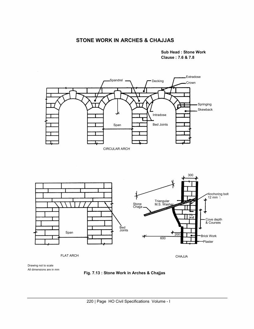
STONE WORK IN ARCHES & CHAJJAS
Sub Head : Stone Work Clause : 7.6 & 7.8
Extradose
Span
Spandrel Span
CIRCULAR ARCH
Bed Joints
Stone Chajja
Decking
Intradose
Bed Joints
Triangular M.S. Washer
200
600
Crown 300 70
Springing Skewback
Anchoring bolt 12 mm
Cove depth & Courses
Brick Work
Plaster Drawing not to scale
FLAT ARCH
CHAJJA
All dimensions are in mm Fig. 7.13 : Stone Work in Arches & Chajjas
220 | Page HO Civil Specifications Volume - I
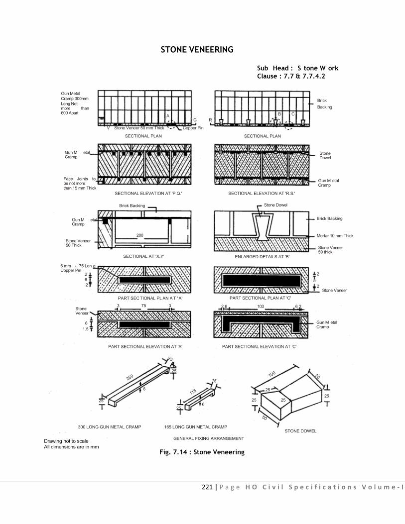
221 | P a g e H O C i v i l S p e c i f i c a t i o n s V o l u m e - I
STONE VENEERING Sub Head : S tone W ork Clause : 7.7 & 7.7.4.2
Gun Metal Cramp 300mm Long Not more than 600 Apart
Gun M etal Cramp
Face Joints to be not more than 15 mm Thick
Gun M etal Cramp
Stone Veneer 50 Thick
6 mm - 75 Lon g Copper Pin
2 6 2
Stone Veneer
6
1.5
25
A G R
V Stone Veneer 50 mm Thick Copper Pin
SECTIONAL PLAN
SECTIONAL ELEVATION AT 'P.Q.'
Brick Backing
200
SECTIONAL AT 'X.Y'
PART SEC TIONAL PL AN A T ' A'
3 75 3
PART SECTIONAL ELEVATION AT 'A'
25
6
6
Brick Backing
B C
SECTIONAL PLAN
Stone Dowel
Gun M etal Cramp
SECTIONAL ELEVATION AT 'R.S.'
Stone Dowel
Brick Backing
Mortar 10 mm Thick
Stone Veneer 50 thick
ENLARGED DETAILS AT 'B'
2 5
2 Stone Veneer
PART SECTIONAL PLAN AT 'C'
2 6 103 6 2
Gun M etal Cramp
PART SECTIONAL ELEVATION AT 'C'
25 25
25 25
25
300 LONG GUN METAL CRAMP
Drawing not to scale All dimensions are in mm
165 LONG GUN METAL CRAMP STONE DOWEL
GENERAL FIXING ARRANGEMENT
Fig. 7.14 : Stone Veneering

222 | Page HO Civil Specifications Volume - I
STONE VENEERING (Typical Fixing Arrangement)
Sub Head : Stone Work Clause : 7.7.4.2 & 7.7.4.6
50 25
Brick Wall
PLAN PLAN
L
25
30
20620 20
2420
6
25
V = Variable as per Site Requirement Based on Thickness of Veneer Use 6 mm Square Gun
Metal Pin
20
6V
Non Corrosive Dash Fastener with Washer including Bolt of Min. S ize 55 x 7 mm
Stone Veneering
Mortar as Specified
R.C.C. Wall
Mortar 10 mm Thick
80 mm or as Specified
SECTION FRONT ELEVATION
Face Joints not to be more than 5 mm
Fig. 7.15A : Cramp for Brick Backing
ELEVATION
FRONT ELEVATION SIDE ELEVATION
Fig. 7.15B : Cramp for R.C.C. Work Backing
Fig. 7.15C :Typical Details of Cramps for R.C.C. Backing
70
6
70
8 9 8
L = 115 MM for Half Brick BackingL = 150 MM for Full Brick Backing
Drawing not to scale All dimensions are in mm
Fig. 7.15 : Stone Veneering (Typical Fixing Arrangement)

223 | Page HO Civil Specifications Volume - I
GENERAL ARRANGEMENT OF CRAMPS
Sub Head : Stone Work Clause : 7.7.4.3
A B C
D E F
G H
Note : Cramps arrangement is shown above for veneerings with longer sides vertical. For veneerings having the longer sides horizontal, cramps would be arranged to suit the altered positions.
Drawing not to scale
Fig. 7.16 : General Arrangement of Cramps

224 | P a g e H O C i v i l S p e c i f i c a t i o n s V o l u m e - I
8.0: Marble Work

225 | P a g e H O C i v i l S p e c i f i c a t i o n s V o l u m e - I
CONTENTS
Clause No. Brief Description Page
List of Mandatory Tests 226
List of Bureau of Indian Standard Codes 227 8.0 General 228 8.1 Classification 228 8.2 Sizes and Tolerances 229 8.3 Physical Properties 229 8.4 Sampling 230 8.5 Marble Work - Table Rubbed and Polished (Plain Work) 230 8.6 Wall Lining / Veneer Work 233 8.7 Marble Stone Flooring and Marble Stone in Risers of Steps and 235
Skirting Fig. 8.1 Marble Stone Veneering (General Fixing Arrangement) 236 Fig. 8.2 Marble Stone Veneering (Typical Fixing Arrangement) 237 Fig. 8.3 General Arrangement of Cramps 238 Fig. 8.4 Marble Slab Urinal Partition 239
.

226 | P a g e H O C i v i l S p e c i f i c a t i o n s V o l u m e - I
LIST OF MANDATORY TESTS
Materia l Clause Test Field/ Test Minimum Qunatity Frequency
Laboratory Procedure o f materia l/ of te sting Test work for carrying
out the te s t Marble 8.3 (i) Moisture Laboratory IS 1124 100 Sq.m. 100 sqm. or
(Table 8.2) Absorption part thereof. (ii) Hardness Test -do- Mho’s Scale -do- -do- (iii) Specific Gravity -do- IS 1122 -do- -do-
Granite (i) Moisture -do- IS 1124 -do- -do- (ii) Specific Gravity -do- IS 1122 -do- -do-
.

227 | P a g e H O C i v i l S p e c i f i c a t i o n s V o l u m e - I
LIST OF BUREAU OF INDIAN STANDARDS CODES
S. No. IS . No. Subject
1. IS 1122 Method of test for determination of true specific gravity of natural building stones.
2. IS 1124 Method of test for determination of water absorption, apparent specific gravity and porosity of natural building stones.
3. IS 1130 Marble (blocks, slabs and tiles). 4. IS 4101 (Part 1) Code of practice for external facing and veneers: Stone facing. 5. IS 3316 Specifications for structural granite 6. IS 14223 (Part 1) Polished Building Stones (Part-1) Granite
.

228 | P a g e H O C i v i l S p e c i f i c a t i o n s V o l u m e - I
8.0 MARBLE WORK
8.0 GENERAL Marble shall be har d, sound, dense and hom ogeneous in texture w ith crystalline texture as far as
possible. It shall generally be uniform in colour and free from stains, cracks, decay and weathering.
8.0.1 Marbles are m etamorphic rocks capable of taking polish, formed from the re-crystallization of lime stones or dolomitic l ime stones and are distinguished f rom l ime s tone by even v isibly c rystalined nature and no flaggy stratification.
Note : Marble is a product of nature hence it is difficult to guarantee uniformity of colour, veining or other characteristics that may be represented in any sample submitted. A sample will indicate only an average of colour, veining and other general texture and specified finish.
8.1 CLASSIFICATION The marble blocks, slabs and tiles shall be classified broadly in the following two categories:
8.1.1 White Marble Raj Nagar (pla in white ) Marble :
It shall be plain white marble with coarse grains predominantly showing mica particles giving reflection in light.
8.1.2 Coloured Marble (i) Plain Black Marble
Black marble sawn along veins locally known as ‘Peta Pasu sawing’ available at Bhainslana. (ii) Black Zebra Marble/ Cuddapa Balck
(a) Bha ins lana Black Zebra Marble : Black marble hav ing grey or white veins available at Bhainslana. (b) Kishangarh Black Zebra Marble : Black marble with g rey and/or white veins available at Kishangarh. (c) Abu Black Zebra Marble : Black marble having white patches and streaks available at Abu. (d) Narnaul Black Zebra Marble s : Black marble with thin white veins available at Narnaul. (e) Cudappa Black Marbles: Black Marble from Cuddapa
(iii) Green Marble (a) Baroda Green Marble : Dark green marble with flowery pattern available at Baroda. (b) Abu G re e n Ma rble : Light green marble with green and/or brown streaks on white ground available at Ambaji. (c) Fa lna Green Marble : Green marble with prominent yellowish pattern available at Falna. (d) Bundi G reen Marble : Green m arble w ith pi nkish shades av ailable at U mar, ( Bundi).
(iv)Grey Marble (a) Kumari Grey Marble : Grey marble having light blue shades available at Makrana. (b) Bundi G rey Marble : Grey Marble with pink or green or black streaks available at Umar (Bundi).
(v) Brown Marble (a) Bar Brown Marble/Brown Marble with light and dark brown shades available at Bar. (b) Narnaul Brown Marble
Brown marble having teak wood shades available at Narnaul.
8.1.3 Granite Stone It shall be of any colour and size as directed by Engineer-in-Charge. Granite shall be plain machine cut
and mirror polished. The stone shall be smooth and of even surface without holes or pits. .

229 | P a g e H O C i v i l S p e c i f i c a t i o n s V o l u m e - I
8.2 SIZES AND TOLERANCES
The size of marble blocks, slabs and tiles shall be as mentioned in Table 8.1.
TABLE 8.1 Sizes of Marble Blocks, Slabs and Tiles
Length Width Thickness
1. Blocks 30 to 250 30 to 100 30 to 90 2. Slabs 70 to 250 30 to 100 2 to 15 3. Tiles 10 to 60 10 to 60 0.8 to 2.4
(1) All dimensions are in centimetre. (2) The length and width, of the blocks shall be in multiple of 30 cm. (3) Length and width of slab shall be in multiple of 10 cm. and thickness in multiple of 1 cm. (4) Tiles shall be square cut and linear dimensions in multiple of 10 cm. (5) Only slabs and tiles shall be machine cut and factory made. (6) For 8 mm thick tiles, special precautions will be required for fixing them like using special adhesive as per manufacturer’s specifications. Such tiles are not suitable for outside veneering work exposed to rains/sun if used in large areas in continuous stretches. For tiles of thickness 20 mm and above cramps may be provided if approved by Engineer-in-Charge.
Tolerance The following tolerances shall be allowed in the dimension of blocks, slabs and tiles: Tolerance
Blocks (a) Length + 2 per cent (b) Width + 2 per cent (c) Thickness + 2 per cent
S labs (a) Length + 2 per cent (b) Width + 2 per cent (c) Thickness + 3 per cent
Tiles (a) Linear dimension + 3 per cent (b) Thickness + 1 per cent The s izes other than those mentioned abov e may be provided as di rected b y the Engineer-in-Charge
and nothing extra shall be payble on this account.
8.3 PHYSICAL PROPERTIES
8.3.1 The physical properties of marble for blocks, slabs and tiles and method of tests are mentioned in Table 8.2.
TABLE 8.2 Physical Properties of Marble & Granite
Marble Granite Characteris tic Marble Requirements Method of te s t Granite Requirement Method of tes t
(1) Moisture absorp- Max. 0.4% IS 1124 Max. 0.50% IS 1124 tion after 24 hrs by weight immersion in cold water
(2) Hardness Min. 3 Mhos scale __ __
(3) Specific Gravity Min. 2.5 IS 1122 Min. 2.6 IS 1122
.

230 | P a g e H O C i v i l S p e c i f i c a t i o n s V o l u m e - I
8.3.2 Approval of Sample
Before s tarting the work, the contractor shall get samples of marble approved by the Engineer-in- Charge. Approved samples shall be ke pt in the cus tody of the Engineer-in-Charge and the marble supplied and us ed on t he work shall conform to samples w ith regard t o soundness, colour, veining and general texture. 8.4 SAMPLING
In any consignment al l t he bl ocks/slabs/tiles of the same g roup, s ize and finish shall be g rouped together to constitute a l ot. Sample shall be s elected and t ested separately for each lot for determining its conformity or otherwise to the re quirements of t he specification. The nu mber of blocks/slabs/tiles to be selected for the samples shall depend upon t he size of the lot and s hall be in accordance with the Table 8.3.
TABLE 8.3 Sample Size and Criteria for Conformity
Number of Blocks Number of blocks Permiss ible number Sub sample s labs/Tiles in the lo t s labs/ Tiles to be of defectives S ize in no.
selected in s ample (1) (2) (3) (4)
Up to 50 As per site Engineer 0 2 50 to 200 5 0 2 201 to 500 8 0 3 501 to 1000 20 1 4
Note: The blocks/slabs/tiles in the sample shall be taken at random and in order to ensure to randomness of selection, random tables may be used. Explanation 1 : All the blocks/slabs/tiles, selected in the sample, shall be examined for dimensions workmanship and general requirements.
Any block/slab/tile fa iling in any o ne o r more of t he above requirements shall be c onsidered as defective. A lot shall be considered as conforming to these requirements i f the number of defectives obtained is not more than permissible no. of defectives given in Col. 3 of table 8.3
Explanation 2 : The lot having been found satisfactory with respect to dimensions, workmanship and general requirement shall be tested for physical properties of the marble. For this purpose a sub sample of the s ize g iven i n Col. 4 of T able 8. 3 shall b e s elected a t ra ndom. T hese bl ocks/slabs/tiles i n t he s ub sample shall be tested for moisture absorption, hardness and specified gravity. The lot shall be considered having satisfied the requirements of the physical properties if none of the blocks/slabs/tiles tested for the requirements fails in any of these tests. 8.5 MARBLE WORK - TABLE RUBBED AND POLISHED (PLAIN WORK)
Marble work in steps, jambs, columns and other plain work shall be as specified below: Joints in staircase treads, kitchen platforms shall be permitted only at curvature or when width/length is
more than 0 .6/2 m trs. respectively. N umber of joints in eac h d irection s hall no t be m ore than o ne number for every 2 mtrs. length beyond the initial 2.00 m length. Additional joints due to curvature or for providing fixture shall be provide judiciously as given in sketch ‘A’ below.

231 | P a g e H O C i v i l S p e c i f i c a t i o n s V o l u m e - I
0.6
m
1 m
3.8 m
0.6m 1.0m
0.9 m 0.6 m
(I) T READ/STEPS IN STAIR CASE
8.5.1 Dressing, Cutting and Rubbing
(II) TYPICAL KITCHEN PLATFORM INDICATING LOCATION OF
JOINT IN MARBLE TOP
SKETCH (A)
Every marble stone shall be gang saw/machine cut to the required s ize and shape, chisel dressed machine f inished on al l beds and j oints, so as to be f ree f rom any waviness and t o give truly vertical, horizontal, radial or circular joints as required. The exposed faces and sides of stones forming joints upto 6mm. from the face shall be f ine tooled machine cut such that a straight edge laid along the face of the stone is in contact with every point on it. All window sills, tread of steps, counters vanities moulding edges etc. shall be machine cut & polished to give high gloss mirror finish as per direction of Engineer- in-Charge. These surfaces shall then be rubbed smooth. All v isible angles and edges shall be t rue, square and free from chipping. Beyond the depth of 6 mm from face, the joints shall be dressed with a slight splay so that the thickness of joint increases, in an i nverted V shape as shown in Fig. below. The surfaces of the stones coming in contact with backing need not be chisel dressed.
EXTERNAL FACE 1.5 mm
6 mm
INVERTED V-SHAPE JOINT
A sample of dressed and rubbed stone shall be prepared for approval and i t shall be kept on worksite after being approved by the Engineer-in Charge.
8.5.2 Mortar The mortar used for jointing shall be as specified.
8.5.3 Laying All marble stones shall be wetted before p lacing in position. These shall then be f loated on mortar
and bedded properly in position with wooden mallets without the use of chips or under pinning of any sort.
The walls and pillars shall be carried up truly in plumb or battered as shown in the drawings. All courses shall be laid truly horizontal and all vertical joints shall be truly vertical.
In case of work without backing of br ick work or c oursed rubble masonry, face stone shall be laid in headers and s tretchers al ternatively unless otherwise di rected. The headers shall be arrang ed to come

232 | P a g e H O C i v i l S p e c i f i c a t i o n s V o l u m e - I
as near ly as pos sible in t he middle o f stretchers above and bel ow. S tone s hall be l aid i n regular courses of not less than 15 cm in height and all courses shall be of the same height unless otherwise specified.
For work facing with backing of br ick work or coursed rubble masonry, face stone shall be l aid in alternate courses of header and stretchers unless otherwise directed. Face stone and bond stone courses shall have break joint on t he face of atleast half the height of the standard course and the bond shall be c arefully maintained through ou t. A ll the connected masonry in a structure shall be carried up nearly at one uniform level throughout but where breaks are unavoidable the joints shall be m ade in good long steps so as to prevent cracks developing between new and old work.
When necessary jib crane or other mechanical appliances shall be used to hoist the heavy pieces of stones and place these in to correct positions, care being taken that the corners of the stone are not damaged. Stone shall be covered with gunny bags, before putting chain or rope is passed over it, and it shall be handled carefully. No piece which has been damaged shall be used in work. The matching of grains shall be carried out as directed by the Engineer-in-Charge.
8.5.4 Bond Stone Bond or through stones running right through the thickness of walls, shall be provided in walls upto
60 cm thick and i n case of wall above 60 c m thickness a s et of two or more bond s tones overlapping each other by atleast 15 cm shall be provided in a line from face to back.
At least one bond stone or a set of bond stones shall be provided for every 0.5 sqm of the wall surface. All bond stones shall be marked suitably as directed by the Engineer-in-Charge.
8.5.5 Joints The depth of joints 6 mm from the face shall be uniform and as fine as possible but shall be not more
than 1.5 mm thick on the exposed face. Beyond the depth of 6 m m from face, the thickness of joints shall increase in an inverted V shape so as to give good mortar bond between two stones. The inverted portion of the joints shall be filled with bedding mortar and the face 6 mm portion with pointing mortar.
8.5.6 Curing The work shall be kept constantly moist on all faces for a period of atleast seven days.
8.5.7 Finishing After the marble work is cured, it shall be rubbed with carborandum stone of different grades no. 60,
120 and 320 i n succession or with electrical rubbing machines rubbed with carborandum i tems 0 to 6 nos.in succession, so as to give a pl ane true and h ighly smooth surface. It shall then be cleaned with a solution of oxalic acid, washed and finished clean.
8.5.8 Protection Green work shall be protected from rain by suitable coverings. The work shall a lso be suitably
protected from damage during construction.
8.5.9 Scaffolding Double s caffolding hav ing two sets o f v ertical supports s hall be pr ovided w here nec essary. The
supports shall be sound and strong, t ied together by horizontal pieces over which the scaffolding plank shall be fixed.
8.5.10 Tolerances As per para 8.2 Note: The above Para 8 .5. also app lies to the Ashlar masonry referred in Chapter No. 7.0 - Stone Work.

233 | P a g e H O C i v i l S p e c i f i c a t i o n s V o l u m e - I
8.5.11 Measurements
For plain work: Measurements shall be taken correct to a cm in length and breadth and correct to 0.5 cm in thickness.
8.5.11.1 In the case of radially dressed or circular stone used in the work, the dimensions of the circumscribing rectangle of the dressed stone, shall be m easured correct to a centimetre and t hickness, correct to 0.5 cm.
The cubical contents shall be calculated in cubic decimetre nearest to two places of decimal.
8.5.11.2 The marble work in arches and dom es shall be m easured as for plain work, but extra shall be allowed for such work over the rate for plain work. 8.5.11.3 Sunk or moulded work in marble shall be measured by volume as per plain marble work or work in arches or domes as the case may be on the basis of circumscribed rectangular block of the finished work but extra s hall be paid f or s uch work over t he r ate f or plain w ork for work i n ar ches and do mes. For the purpose of extra payment, volume of every stone sunk or moulded shall be considered.
8.5.12 Rate The rate includes the cost of materials and labour required for all the operations i/c cutting of
recesses in wall cutting moulding corners edge rounding finishing & polishing as specified.
8.5.13 Use of Finished Marble Slabs and Tiles In case such finished tiles are used, these shall be measured and paid for separately.
8.6 WALL LINING/VENEER WORK
8.6.1 Unless and otherwise specified in the nomenclature of the i tem, the marble slabs used for wall lining/veneer work shall be gang saw cut (polished & machine cut) and conform to dimensions given in Table 8.1 above.
Back shall not be polished/ cut in order to ensure a good grip with the hearting of backing. The cut slabs shall be of the thickness as specified w ith a tolerance permissible under para 8.2 above. The tolerance in wall lining when straight edge of 3 m length is placed should not be more than 2 mm.
8.6.2 Laying The stone shall be wetted before laying. They shall then be fixed with mortar in position without the
use of chips or under pinning of any sort. Care shall be taken to match the grains of veneer work as directed by the Engineer-in-Charge. For purpose of matching the g rains, the marble slabs shall be selected judiciously hav ing uni form pattern of veins/streaks. Preferably the slabs shall be those got out of the same block from the quarry. The area to be veneered shall be reproduced on the ground and the marble slabs laid in position and arranged in the manner to give the desired matching of grains. Any adjustment needed for achieving the best results shall be then carried out by replacing or interchanging the particular slabs. Special care shall be taken to achieve the continuity of grains between the two slabs one above t he other along the horizontal j oints. This shall t hen be got approved by the Engineer-in- Charge and eac h marble s labs num bered properly and the same number shall be marked on a s eparate drawing as well as on t he surface to be ac tually veneered, so as to ensure the f ixing of the particular slabs in the correct location.
For the facing of the columns also the same procedure as mentioned above shall be followed.
8.6.2.1 Where so desired, the adjoining stones shall be secured to each other by means of copper pins 75 mm long and 6 mm diameter or as specified.

234 | P a g e H O C i v i l S p e c i f i c a t i o n s V o l u m e - I
8.6.2.2 The stones shall be secured to the backing by means of cramps. The material for cramps shall have h igh resistance to corrosion under conditions of dampness and against the chemical action of mortar or concrete in which cramps are usually embedded.
Cramps shall be of 25 × 6 mm and 3 0 cm long in case of backing of stone masonry walls and brick masonry walls thicker than 230 mm. In case of backing with brick masonry walls 230 mm or less thick or RCC members cramps shall be of 25 × 6 mm and length as per requirement made out of gun metal or any other metal specified in para 8 .6.2.6. Generally the outer length of cramp in hal f brick work backing shall be 115 mm and in one brick work backing it shall be 150 mm. Typical shape & details of cramps for such backing are as indicated in Fig. 8.2 for general guidance. This can be modified as directed by the Engineer-in-Charge if so, required at site. Cramps shall be spaced not more 60 cm apart horizontally.
Alternatively the stone may be secured to the backing by means of stone dowels 10 x 5 x 2.5 cm as per shape indicated in Fig. 8.1.
8.6.2.3 The adjoining stones shall be secured to each other by means of gun metal cramps or copper pins of the specified size. Cramps may be attached to its sides (see Fig. 8.3A, 8.3B) or top and bottom (See Fig. 8.3C, D, E, F) or sides, top and bottom (see Fig. 8.3G, 8.3H). The general arrangement of cramps required for fixing facing unit to the wall are illustrated in Fig 8.3. The actual number of cramps and their sections, however, shall be as per requirements of design to carry the loads.
8.6.2.4 Where cramps are used to hold the unit in position only, the facings shall be provided with a continuous support on which the stones rest at the g round level and other s torey levels, the support being in the form of projection from or recess into the concrete floor s lab, or a beam between the columns or a m etal angle at tached to the f loor s lab o r beams. These supports shall preferably be at vertical intervals not more than 3.5 m apar t and al so over the heads of al l openings. Such supports shall also be provided where there is transition from thin facing below to thick facings above.
8.6.2.5 Alternatively cramps may be used to hold the units in position and in addition to support the units thus transferring the weight of the units to the backing. Such cramps should be properly designed as per IS 4101 (Part 1).
8.6.2.6 The cramps may be of copper alloyed with zinc, tin, nickel, lead or stainless steel.
8.6.2.7 The pins, cramps and dowels shall be laid in cement mortar 1:2 (1 cement : 2 fine sand) and their samples got approved by the Engineer-in-Charge and kept at site.
8.6.3 Joints All joints shall be full of mortar. Special care shall be taken to see that groundings for veneer work
are full o f mortar. If any h ollow groundings are detected b y t apping the face s tones, these shall be taken out and relaid. The thickness of the face joints shall be uniform, straight and as f ine as possible, not more than 1.5 mm and in the face joint, the top 6 mm depth shall be f illed with mortar specified for the pointing.
8.6.4 Mortar The mortar used for jointing slabs shall be as specified.
8.6.5 Curing, Finishing, Protection and Scaffolding It shall be as specified under 8.5.6, 8.5.7, 8.5.8 and 8.5.9.
8.6.6 Measurements The length and breadth shall be measured correct to a c m. In case of radially dressed or c ircular
slabs used in the work, the dimensions of the circumscribing rectangles of the dressed s tone used in the work, shall be measured & paid for. The area shall be calculated in sqm nearest to two places of decimal.
235 | P a g e H O C i v i l S p e c i f i c a t i o n s V o l u m e - I
Marble work in lining upto 4 cm thickness shall be paid by area under veneer work and lining of greater thickness paid by volume under plain marble work.
8.6.7 Rate The rate includes the cost of materials and l abour required for al l the operations described above
except for the cost of providing and fixing of dowel and cramps which shall be paid for separately, unless otherwise stipulated in the item of work.
When factory made finished slabs and tiles are used, no further finishing as mentioned in para 8.5.7 shall be required nor anything extra shall be payable.
8.7 MARBLE STONE FLOORING AND MARBLE STONE IN RISERS OF STEPS AND SKIRTING Refer to relevant clause in subhead 11.0 of flooring of Specifications.
8.7.0 Marble Slab Urinal Partitions The partitions shall be of marble slab embedded in the wall. The size and shape of the marbles slab
shall be as per direction of Engineer-in-Charge. The finished thickness shall be 18 mm. The specifications for marble/granite stone work, in general, shall be as specified. The marble granite stone shall be cut into slabs of required thickness and shall be one piece. (Fig. 8.4).
8.7.1 Finishing The partition of the slab to be embedded in t he masonry shall be rough dressed. Dressing and
rubbing of the exposed portion of the slab shall be as described. The dressed slab shall be of the thickness as specified with a tolerance of + 1.5mm. The s lab shall be got approved from the Engineer-in- Charge before fixing.
8.7.2 Fixing shall be as specified except that the recess shall be 7.5 cm wide. Fixing shall be done by cutting c hase with chase cutter/fine tools in a recess of 7.5 cm X 7.5 cm f illed with cement concrete 1:2:4 (1 cement : 2 coarse sand : 4 graded stone aggregate 6mm nominal size). Fixing can also be done by epoxy grout in a chase of 2.0 X 7.5 cm as per direction of Engineer-in-Charge.
8.7.3 Measurement shall be as per para 8.6.6. 8.7.4 Rate shall include the cost of labour and materials involved in all the operations described above including the leaving/cutting of recess in the wall, moulding, curves, edge rounding, f inishing and polishing as specified.

236 | P a g e H O C i v i l S p e c i f i c a t i o n s V o l u m e - I
MARBLE STONE VENEERING Sub Head : Marble Work Clause : 8.6.2.2
Gun Metal Cramp 600mm Long Not more than 600 Apart
Gun Metal Cramp
Face Joints to be not more than 15 mm Thick
Gun Metal Cramp
Stone Veneer 50 Thick
6 mm - 75 Long Copper Pin
2 6 2
Stone Veneer
5
1.5
25
A G R
V Stone Veneer 50 mm Thick Copper Pin
SECTIONAL PLAN
SECTIONAL ELEVATION AT 'P.Q.'
Brick Backing
200
SECTION AT 'X.Y'
PART SECTIONAL PLAN AT 'A'
3 75 3
PART SECTIONAL ELEVATION AT 'A'
250 25
15
6 115
25 6
Brick Backing
B C
SECTIONAL PLAN
Stone Dowel
Gun Metal Cramp
ENLARGED DETAILS AT 'R.S.'
Stone Dowel
Brick Backing
Mortar 10 mm Thick
Stone Veneer 50 thick
ENLARGED DETAILS AT 'B'
2 5
2 Stone Veneer
PART SECTIONAL PLAN AT 'C'
2 6 103 6 2
Gun M etal Cramp
PART SECTIONAL ELEVATION AT 'C' 100 50
25 25
25 25
50
300 LONG GUN METAL CRAMP 165 LONG GUN METAL CRAMP STONE DOWEL
Drawing not to scale All dimensions are in mm
Fig. 8.1 : Marble Stone Veneering (General Fixing Arrangement)
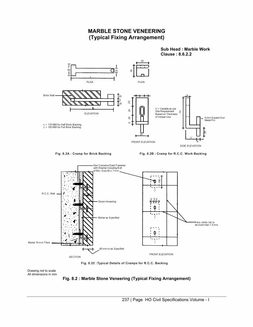
237 | Page HO Civil Specifications Volume - I
MARBLE STONE VENEERING (Typical Fixing Arrangement)
Sub Head : Marble Work Clause : 8.6.2.2
50 25
Brick Wall
PLAN PLAN
L
25
30
20620 20
2420
6
25
V = Variable as per Site Requirement Based on Thickness of Veneer Use 6 mm Square Gun
Metal Pin
20
6V
Non Corrosive Dash Fastener with Washer including Bolt of Min. S ize 55 x 7 mm
Stone Veneering
Mortar as Specified
R.C.C. Wall
Mortar 10 mm Thick
80 mm or as Specified
SECTION FRONT ELEVATION
Face Joints not to be more than 1.5 mm
Fig. 8.2A : Cramp for Brick Backing
ELEVATION
FRONT ELEVATION SIDE ELEVATION
Fig. 8.2B : Cramp for R.C.C. Work Backing
Fig. 8.2C :Typical Details of Cramps for R.C.C. Backing
70
6
70
8 9 8
L = 115 MM for Half Brick BackingL = 150 MM for Full Brick Backing
EQEQ
Drawing not to scale All dimensions in mm
Fig. 8.2 : Marble Stone Veneering (Typical Fixing Arrangement)

238 | Page HO Civil Specifications Volume - I
GENERAL ARRANGEMENTS OF CRAMPS
Sub Head : Marble Work Clause : 8.6.2.3
A B C
D E F
G H
Note : Cramps arrangement is shown above for veneerings with longer sides vertical. For veneerings having the longer sides horizontal cramps would be arranged to suit the altered positions.
Drawing not to Scale
Fig. 8.3 : General Arrangements of Cramps
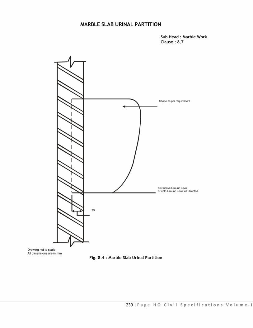
239 | P a g e H O C i v i l S p e c i f i c a t i o n s V o l u m e - I
MARBLE SLAB URINAL PARTITION Sub Head : Marble Work Clause : 8.7
Shape as per requirement
450 above Ground Level or upto Ground Level as Directed
75 Drawing not to scale All dimensions are in mm
Fig. 8.4 : Marble Slab Urinal Partition
240 | P a g e H O C i v i l S p e c i f i c a t i o n s V o l u m e - I
9.0: Wood Work

241 | P a g e H O C i v i l S p e c i f i c a t i o n s V o l u m e - I
CONTENTS
Clause No. Brief Description Page No.
List of Mandatory Tests 244
List of Bureau of Indian Standard Codes 245 9.0 Terminology 247 9.1 Timber 248 9.2 Panelling Material 251 9.3 Door, Window and Ventilator Frames 257 9.4 False Ceiling and Partition Frames 258 9.5 Trusses 258 9.6 Panelled Glazed or Panelled and Glazed Shutters 259 9.7 Flush Door Shutters 264 9.8 Wire Gauze Fly Proof Shutters 266 9.9 Wall Lining 267 9.10 Shelves 268 9.11 Trellis (Jaffri) Work 268 9.12 Pelmets 268 9.13 Hold Fasts 269 9.14 Expanded Metal, Hard Drawn Steel Wire Fabric and Wire Gauze in 269
Wooden Frames 9.15 Fittings 269 9.16 Laminated Veneer Lumber (LVL) - DELETED 278 9.17 Partitions 279 9.18 UPVC Door Frames - DELETED 279 9.19 PVC Door Shutters - DELETED 279 9.20 PVC Door Frame 279 9.21 30mm Thick Panel PVC Door Shutter 280
.

242 | P a g e H O C i v i l S p e c i f i c a t i o n s V o l u m e - I
9.22 Fibre Glass Reinforced Plastic (FRP) Door Frames - DELETED 280 9.23 Fibre Glass Reinforced Plastic (FRP) Shutters - DELETED 281 9.24 Solid PVC Foam Profile Doors - DELETED 281 9.25 Solid PVC Foam Shutters - DELETED 281 9.26 Factory Made Fibre Glass Reinforced Plastic Chajja - DELETED 281 9.27 Wall Panelling 281 Appendix A Permissible Defects for Various Grade of Timbers 282 Appendix B Different Climatic Zones for Moisture Content of Timber 283 Appendix C Moisture Content of Timber 284 Appendix D Physical and Mechanical Properties of Plywood 285 Appendix E Physical and Mechanical Properties of FPT or Graded Particle Board. 285 Appendix F Test for Flush Door Shutters 286 Appendix G Test for Mortice Locks 288 Appendix H Schedule of Fitting for Doors and Windows 289 Appendix I Method of Test for Edge Straightness and Squareness of Plywood 290 Appendix J Method of Test for Edge Straightness and Squareness of Coir Veneer
Board - DELETED Appendix K Method for Test of Coir Veneer Board for Determination of Glue Shear
Strength - DELETED Fig. 9.1 Joints in Timber 291
Fig. 9.2 Terminology Timber Door, Window and Ventilator Components 292
Fig. 9.3 Wooden Flush Door Shutters 293
Fig. 9.4 Hold Fast 294
Fig. 9.5 to 9.6 Hinges 295
Fig. 9.7 Sliding Door Bolts 297
Fig. 9.8 Barrel Tower Bolts 298
Fig. 9.9 Pull Bolt Locks 299
.

243 | P a g e H O C i v i l S p e c i f i c a t i o n s V o l u m e - I
Fig. 9.10 Mortice Lock & Latch 300 Fig. 9.11 Mortice Night Latch 301 Fig. 9.12 Handles for Doors & Windows 302 Fig. 9.13 Floor Door Stopper - Cast Type 304 Fig. 9.14 Window Stay & Hooks & Eyes 304 Fig. 9.15 Hasps & Staples 305 Fig. 9.16 LVL Shutter 306 Fig. 9.17 Partitions 307 Fig. 9.18 UPVC Door Frame - DELETED 307 Fig. 9.19 24 mm Thick PVC Door Shutters - DELETED 307 Fig. 9.20 30 mm Thick PVC Door Shutters - DELETED 307 Fig. 9.21 PVC Door Frame 308 Fig. 9.22 30 mm Thick Panel PVC Door Shutter 309 Fig. 9.23 FRP Door Frame Fig. 9.24 Typical Sketch of FRP Door Shutter Fig. 9.24 B Sketch Illustrating Dimensions of shutter 310 Fig. 9.25 Solid PVC Foam Profile Shutter 311 Fig. 9.26 Solid PVC Foam Shutter (28 mm Thick) - DELETED Fig. 9.27 FRP Chajja - DELETED Fig. 9.28 Wall Panelling 312
.

244 | P a g e H O C i v i l S p e c i f i c a t i o n s V o l u m e - I
LIST OF MANDATORY TESTS
Materia l Clause Tes t Fie ld/ Tes t Min. Frequency
Laboratory Tes t Procedure Quantity of of Testing Materia l for carrying out the te st
1 2 3 4 5 6 7 Timber 9.1.6 Moisture Field (by Appendix ‘C’ 1 cum Every one
content moisture meter) cum or part laboratory test thereof. as required by Engineer-in- Charge
Flush door 9.7.10 End immersion Laboratory IS 2202 26 shutters As per Test knife test Appendix ‘F’ sampling Adhesion Test and testing
specified in clause 9.7.11
Mortice 9.15.13 Testing of Laboratory IS 2209- 50 Nos 100 or part Locks spring Appendix ‘G’ thereof.
.


247 | P a g e H O C i v i l S p e c i f i c a t i o n s V o l u m e - I
9.0 WOOD WORK AND P.V.C. WORK
9.0 TERMINOLOGY
Ballies : Thin round poles usually without bark. Beam : A s tructural timber generally long in proportion to i ts width and thickness and used for supporting load primarily by its internal resistance to bending.
Block Board : A Board having a c ore made up of s trips of wood, each no t exceeding 25 mm in width, laid separately or glued or otherwise joined to form a slab which is glued between two or more outer veneers with the direction of the grain of the core blocks running at right angles to that of the adjacent outer veneers. Core : The inner layers of a composite wood product.
Cross B and : A general term i ndicating a t ransverse l ayer of veneer or v eneers i n composite w ood products. Decorative Veneers : Veneers having attractive appearance due to figure, colour, grain, lusture, etc.
Hard Wood : A conventional term used to denote the wood obtained f rom broad-leaved t rees. I t has no relationship to the physical properties of hardness or s trength. On account of the confusion this word might cause, its use is discouraged.
Freeze Rail : Horizontal member, mortised or otherwise secured to the stiles of a door , provided just below the freeze panel usually provided for decorative purposes in the uppermost portion of the door.
Joint : A prepared connection for joining adjacent pieces of wood, veneer, etc.
Dovetail Joint : A joint at the corner of two pieces in such a way that the notches made to one are fitted exactly into projections of corresponding size and shape made in the other. There are v arious k inds of dovetail joints for instance, lapped dovetail joint, wedge shaped dovetail joint, etc. joined in a w ay which will resist withdrawal except in the direction in which it was assembled (Fig. 9.1C).
Mitred Joint : A joint, between two members at an angle which bisects the joining angle usually the joining faces are cut at 45° to form a right angle (Fig. 9.1B).
Mortise and Tenon Jo int : A j oint i n w hich t he reduc ed e nd (tenon) of one member f its i nto t he corresponding slot (mortise) in another member (Fig. 9.1D). Tongue and Groove Joint : A joint in which a tongue is provided on edge of one member to fit into a corresponding groove on the other (Fig. 9.1A).
Knot : Base of a branch or limb embedded in the tree which becomes visible when it is cut.
Diameter of a Knot : The maximum distance between two points farthest apart on the pe riphery of a round knot, on the face where i t becomes visible. In the case of a spike or splay knot, the maximum width of the knot visible on the face on which it appears shall be taken as its diameter.
Muntin : Small hor izontal or v ertical d ividing bar s w ithin bas ic framework o f a w indow, or door subdividing and supporting the glass panes or panels of doors.

248 | P a g e H O C i v i l S p e c i f i c a t i o n s V o l u m e - I
Particle Board : A board manufactured f rom pa rticles o f wood o r other l ignocellulose material, fo r example, f lakes, granules, s havings, slivers, s plinter aggl omerated, f ormed and pressed t ogether by use of an or ganic binder together with one or more of the agents, such as heat, pressure, moisture and a catalyst. Particle : Distinct particle o r f raction of wood, or other l ignocellulose m aterial p roduced m echanically for use as the aggregate for making a par ticle board. This may be i n the form of f lake, granule, shaving, splinter and sliver. Plywood : A board formed of three or more layers of veneers cemented or glued together, usually with the grain of adjacent veneers running at right angles to each other.
Rebate : A recess along the edge of a piece of timber to receive another piece or a door, sash or a frame. Sapwood : The outer layers of the log, which in the growing tree contain living cells and feed material. The sapwood is usually lighter in colour, and is readily attacked by insects and fungi.
Seasoning : A process involving the reduction of moisture content in timber under more or less controlled conditions towards or to an amount suitable for the purpose for which it is to be used. Seasoned T imber : Timber w hose moisture c ontent has bee n reduced t o the specified minimum, und er more or less controlled processes of drying.
Structural Timber : Timber used in framing and load bearing structures or timber used or intended for use in buildings where strength is the primary consideration.
First Class Wood Individual hard and sound knots shall not be more than 25 mm in diameter and the aggregate area of all
the knots shall not exceed one per cent of the area of the piece.
Second Class Wood Individual hard and sound knot shall not be more than 40 mm in diameter and aggregate of all the
knots shall not exceed one and hal f per cent of the area of the piece. Wood shall be gen erally free from sapwood, but traces of sapwood may be allowed.
9.1 TIMBER Timber is classified as under : (i) Teak wood (ii) Deodar wood (iii) N on-coniferous t imbers o ther t han teak (iv) Coniferous timber other than deodar.
The t imber shall be f ree from decay, fungal growth, boxed heart, pitch pockets o r s treaks on the exposed edges, splits and cracks. The t imber shall be graded as f irst grade and second grade on the basis of the permissible defects in the timber as given in Appendix ‘A’ of Chapter 9.0. For both the grades, knots should be avoided over a specified limit.
9.1.1 Teak Wood (Tectona Grandis) It is of outstanding merit in retention of shape and durability. The heart wood is one of the most
naturally durable woods of the world. It usually remains immune to white ant attack and insect attack for very long periods. It is, however, not always immune from fungus attack (rot). Taken as a whole, good quality teak is very durable, it is relatively easy to saw and work. It can be furnished to a fare surface and takes polish well. It is generally used for making furniture and all important timber construction.
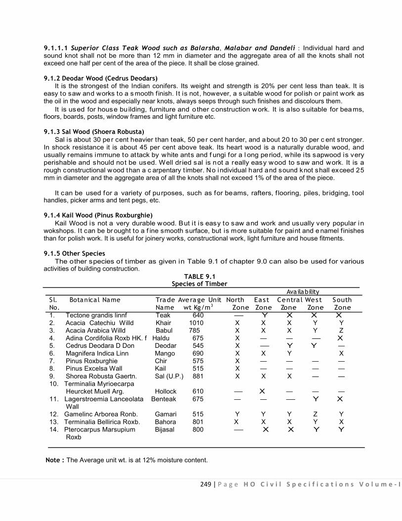
249 | P a g e H O C i v i l S p e c i f i c a t i o n s V o l u m e - I
9.1.1.1 Superior Class Teak Wood such as Balarsha, Malabar and Dandeli : Individual hard and sound knot shall not be more than 12 mm in diameter and the aggregate area of all the knots shall not exceed one half per cent of the area of the piece. It shall be close grained.
9.1.2 Deodar Wood (Cedrus Deodars) It is the strongest of the Indian conifers. Its weight and strength is 20% per cent less than teak. It is
easy to saw and works to a s mooth finish. It is not, however, a s uitable wood for polish or paint work as the oil in the wood and especially near knots, always seeps through such finishes and discolours them.
It is used for house building, furniture and other construction work. It is a lso suitable for beams, floors, boards, posts, window frames and light furniture etc.
9.1.3 Sal Wood (Shoera Robusta) Sal is about 30 pe r cent heavier than teak, 50 pe r cent harder, and about 20 to 30 per c ent stronger.
In shock resistance it is about 45 per cent above teak. Its heart wood is a naturally durable wood, and usually remains immune to attack by white ants and f ungi for a l ong period, while its sapwood is very perishable and should not be used. Well dried sal is not a really easy wood to saw and work. It is a rough constructional wood than a c arpentary t imber. No individual hard and sound knot shall exceed 25 mm in diameter and the aggregate area of all the knots shall not exceed 1% of the area of the piece.
It can be used for a variety of purposes, such as for beams, rafters, f looring, piles, bridging, tool handles, picker arms and tent pegs, etc.
9.1.4 Kail Wood (Pinus Roxburghie) Kail Wood is not a very durable wood. But i t is easy to saw and work and usually very popular in
wokshops. It can be br ought to a f ine smooth surface, but is more suitable for paint and e namel f inishes than for polish work. It is useful for joinery works, constructional work, light furniture and house fitments.
9.1.5 Other Species The other species of timber as given in Table 9.1 of chapter 9.0 can also be used for various
activities of building construction. TABLE 9.1
Species of Timber Availability
S l. Botanica l Name No. 1. Tectone grandis linnf 2. Acacia Catechiu Willd 3. Acacia Arabica Willd
Trade Average Unit North East Centra l West South Name wt Kg/m3 Zone Zone Zone Zone Zone Teak 640 — Y X X X Khair 1010 X X X Y Y Babul 785 X X X Y Z
4. Adina Cordifolia Roxb HK. f Haldu 5. Cedrus Deodara D Don Deodar 6. Magnifera Indica Linn Mango 7. Pinus Roxburghie Chir 8. Pinus Excelsa Wall Kail 9. Shorea Robusta Gaertn. Sal (U.P.) 10. Terminalia Myrioecarpa
Heurcket Muell Arg. Hollock 11. Lagerstroemia Lanceolata Benteak
Wall 12. Gamelinc Arborea Ronb. Gamari 13. Terminalia Bellirica Roxb. Bahora 14. Pterocarpus Marsupium Bijasal
Roxb
675 X — — — X 545 X — Y Y — 690 X X Y X 575 X — — — — 515 X — — — — 881 X X X — —
610 — X — — — 675 — — — Y X
515 Y Y Y Z Y 801 X X X Y X 800 — X X Y Y
Note : The Average unit wt. is at 12% moisture content.
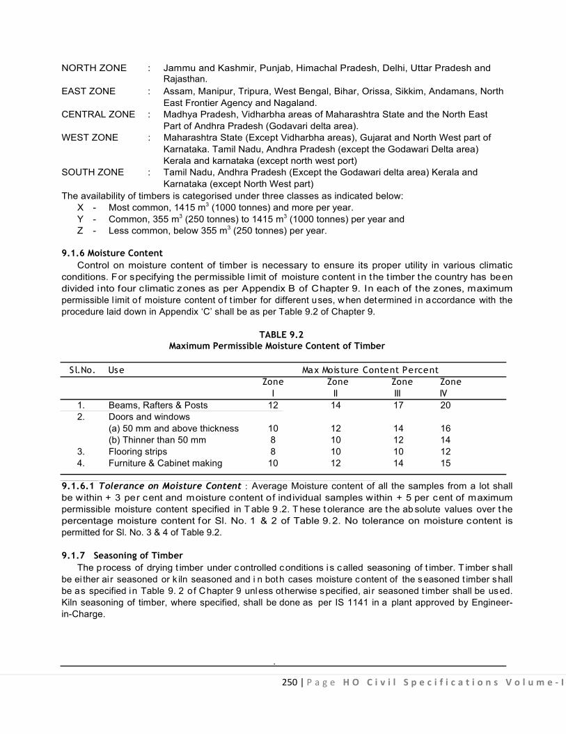
250 | P a g e H O C i v i l S p e c i f i c a t i o n s V o l u m e - I
NORTH ZONE : Jammu and Kashmir, Punjab, Himachal Pradesh, Delhi, Uttar Pradesh and
Rajasthan. EAST ZONE : Assam, Manipur, Tripura, West Bengal, Bihar, Orissa, Sikkim, Andamans, North
East Frontier Agency and Nagaland. CENTRAL ZONE : Madhya Pradesh, Vidharbha areas of Maharashtra State and the North East
Part of Andhra Pradesh (Godavari delta area). WEST ZONE : Maharashtra State (Except Vidharbha areas), Gujarat and North West part of
Karnataka. Tamil Nadu, Andhra Pradesh (except the Godawari Delta area) Kerala and karnataka (except north west port)
SOUTH ZONE : Tamil Nadu, Andhra Pradesh (Except the Godawari delta area) Kerala and Karnataka (except North West part)
The availability of timbers is categorised under three classes as indicated below: X - Most common, 1415 m3 (1000 tonnes) and more per year. Y - Common, 355 m3 (250 tonnes) to 1415 m3 (1000 tonnes) per year and Z - Less common, below 355 m3 (250 tonnes) per year.
9.1.6 Moisture Content
Control on moisture content of timber is necessary to ensure its proper utility in various climatic conditions. For specifying the permissible l imit of moisture content in the t imber the country has been divided into four climatic zones as per Appendix B of Chapter 9. In each of the zones, maximum permissible l imit o f moisture content of t imber for different uses, when determined in accordance with the procedure laid down in Appendix ‘C’ shall be as per Table 9.2 of Chapter 9.
TABLE 9.2
Maximum Permissible Moisture Content of Timber S l.No. Use Max Moisture Content Percent
Zone Zone Zone Zone I II III IV
1. Beams, Rafters & Posts 12 14 17 20 2. Doors and windows
(a) 50 mm and above thickness 10 12 14 16 (b) Thinner than 50 mm 8 10 12 14
3. Flooring strips 8 10 10 12 4. Furniture & Cabinet making 10 12 14 15
9.1.6.1 Tolerance on Moisture Content : Average Moisture content of all the samples from a lot shall be within + 3 per cent and moisture content of individual samples within + 5 per cent of maximum permissible moisture content specified in T able 9 .2. T hese t olerance are the ab solute values over t he percentage moisture content for Sl. No. 1 & 2 of Table 9.2. No tolerance on moisture content is permitted for Sl. No. 3 & 4 of Table 9.2. 9.1.7 Seasoning of Timber
The process of drying t imber under controlled conditions i s called seasoning of t imber. T imber shall be ei ther ai r seasoned or k iln seasoned and i n both cases moisture content of the seasoned t imber shall be as specified in Table 9. 2 of Chapter 9 unless otherwise specified, ai r seasoned t imber shall be used. Kiln seasoning of timber, where specified, shall be done as per IS 1141 in a plant approved by Engineer- in-Charge.
.

251 | P a g e H O C i v i l S p e c i f i c a t i o n s V o l u m e - I
9.1.8 Preservation of Timber
Preservative t reatment does not improve b asic pr operties of t imber but g ives varying de gree of protection against deterioration due t o a ttacks b y f ungi, t ermites, b orers and m arine organisms. P reservative t reatment, where specified, shall be done using Oil type, Organic solvent type or Water-soluble type preservative. Oil type preservatives s hall be us ed i f t he t imber i s not r equired t o be p olished or painted. B efore pr eservative treatment, t he t imber shall be s awn an d seasoned. All surfaces exposed af ter treatment, e xcept due to planing, s hall be t horoughly brushed with t he pr eservation b efore j ointing. P reservative t reatment of t imber shall be done as per IS 401 in a plant approved by the Engineer-in-Charge.
9.2 PANELLING MATERIAL
9.2.1 Timber Timber panels shall be preferably made of timber of larger width. The minimum width and thickness of
a panel shall be 150 mm and 15 mm respectively. When made from more than one piece, the pieces shall be joined with a continuous tongue and groove joint, glued together and reinforced with metal dowels. The grains of t imber panels shall run along the longer dimensions of the panels. The panels shall b e designed such that no single panel exceeds 0.5 square metre in area.
9.2.2 Plywood /Plywood Boards
9.2.2.1 Plywood boards are formed by gluing and pressing three or more layers of veneers with the grains of adjacent veneers running at right angles to each other. The veneers shall be either rotary cut or sliced and s hall be s ufficiently smooth to permit an ev en spread of glue. Face veneers may be ei ther decorative on bot h s ides or one s ide commercial and t he other decorative. P lywood shall be of BWP grade or BWR grade as per IS 303.
9.2.2.2 Adhesive : Adhesive used for bonding BWP grade of plywood boards shall be BWP type synthetic resins conforming to IS 848 .
9.2.2.3 The thickness of all veneers shall be uni form, within a t olerance of ± 5 per c ent. Corresponding veneers on either side of the centre one shall be of the same thickness and species. The requirements of thickness and core veneers shall be as follows:
(a) In 3 pl y boards upto 5 mm thick. The combined thickness of the face veneers shall not exceed twice the thickness of centre ply. (b) In multiply boards, the thickness of any veneer shall not be m ore than thrice the thickness of any other veneer. (c) The sum of the thickness of the veneers in one direction shall approximate to the sum of the thickness of the veneers at right angle to them and shall not be greater than 1.5 times this sum except for 3 ply as specified in (a).
9.2.2.4 Thickness :Plywood boards are available in thickness ranging f rom 3 t o 25 mm. Tolerance in thickness shall be ± 10% for boards upto and including 5 mm; ± 7% for boards from 6 to 9 mm and ± 5% for boards above 9 mm thickness. The boards shall be of uniform thickness and the surfaces of the boards shall be sanded to a smooth finish. Number of plys in plywood boards shall be as per Table 9.3.
TABLE 9. 3
Thickness No. of ply Thickness No. of ply in mm in mm
3,4,5,6 3 12,15,16,19 9 5,6,8,9 5 19,22,25 11 9,12,15,16 7 (Above 11 Ply as ordered)
Note : Plywood of 9 mm thick of 5 or 7 ply may be used generally. .

252 | P a g e H O C i v i l S p e c i f i c a t i o n s V o l u m e - I
9.2.2.5 Moisture content of the plywood boards when tested in accordance with IS 1734 (Part 1) shall not be less than 5 per cent and not more than 15 per cent.
9.2.2.6 Testing : One sample for every 100 sqm or part thereof shall be taken and t esting done a s per IS 303. However, testing may not be done i f the total requirement of plywood boards is less than 30 sqm. All the samples tested shall meet the requirements of physical and mechanical properties of plywood boards specified in Appendix D of Chapter 9. 9.2.3 Particle Boards
9.2.3.1 Particle boards shall be of medium density and manufactured from particles of agro waste, wood or lignocellulose i.e. material blended with adhesive and formed into solid panels under the influence of heat, moisture, pressure etc. The particle boards shall be flat pressed three layered or graded and of Grade-I as per Table 1 of IS 3087. Both surfaces of the boards shall be sanded to obtain a smooth finish and shall conform to IS 3087. 9.2.3.2 Adhesives : Adhesives used for bonding shall be BWP type synthetic resin conforming to IS 848.
9.2.3.3 Thickness and Tolerance : Thickness o f par ticle boards shall be as specified. Tolerance in thickness shall be ± 5% for boards upto and including 25 mm thick and ± 2.5 per cent for boards above 25 mm thickness. Each board shall be of uniform thickness.
9.2.3.4 Testing : One sample for every 100 sqm or part thereof shall be taken and testing done as per IS 3087. However, testing may not be done if the total requirement of particle boards in a work is less than 30 sqm. All the samples tested shall meet the requirement of physical and mechanical properties of particle boards specified in Appendix E of Chapter 9.0. 9.2.4 Veneered Particle Boards
9.2.4.1 Veneered Particle Boards with core of FPT-1 or graded board G rade-I part icle board (I S 3087) with commercial or general purpose veneer (Type-1) or decorative veneers on both faces or with decorative veneer on one face and commercial /general purpose veneers on the other Type-2. Face veneers are bonded using adhesives under the influence of heat and pressure.
9.2.4.2 Adhesives : The adhesive used for bonding veneers shall be BWP or BWR type conforming to IS 848 for grade I veneered particle board.
9.2.4.3 Thickness & Tolerance : Veneered particle boards are available in various thickness 6, 10, 12, 20, 25, 30, 35, 40, 45 & 50 mm.
Tolerance in thickness shall be ± 5%.
9.2.4.4 Testing : One sample for every 100 sqm or part thereof shall be taken and testing done as per IS 3097. However, testing may not be done i f the total requirement of veneered par ticle boards in a work is less t han 30 s qm. A ll t he s amples t ested s hall meet t he requirements o f ph ysical and m echanical properties of veneered particle boards as under:

253 | P a g e H O C i v i l S p e c i f i c a t i o n s V o l u m e - I
Physical and Mechanical properties of Veneered particle board
1. Moisture Content 5-15% 2. Water Absorption
(a) 2 hrs. soaking Not more than 25% (b) 24 hrs. soaking Not more than 50%
3. Water Resistance No sign of disintegration or delamination after 3 hrs. boiling in water.
4. Swelling in Water (a) General absorption for 2 hrs. immersion Not more than 7% (b) Surface absorption for 2 hrs. Not more than 5%
5. Adhesion of plies Knife test
9.2.4.5 Type of face veneers, thickness of veneered par ticle boards and adhesive used for bonding shall be as specified. Unless otherwise stated, exterior grade veneered particle boards with BWP type synthetic resin adhesive shall be used.
9.2.5 Non-Asbestos Fibre Boards
9.2.5.1 Fibre boards shall be of medium density cement board reinforced with wood fibre, produced by fiberizing steamed wood under pressure, blended with adhe sive and wax a nd formed into solid pan els under controlled conditions of heat and pressure as per IS 14862. 9.2.5.2 Adhesives : The adhesive used for bonding shall be BWP type synthetic resin conforming to IS 848. 9.2.5.3 Thickness : Fibre boards are available in thickness 6, 9, 12, 15, 18, 22, 25, 30, 35 & 40 mm. The tolerance in thickness shall be ± 0.3 mm. Thickness of f ibre boards and adhesive used for bonding shall be as specified. Unless otherwise s tated, exterior grade f ibre boards bonded with BWP type synthetic resin adhesive shall be used.
9.2.6 Float Glass, Frosted Glass Float glass used shall be as specified in sub-head 21.0 of this specifications.
For panel exceeding 0.5 sqm in area, the nominal thickness of the g lass to be used shall be as specified.
9.2.7 Wire Cloth (Wire Gauze)
9.2.7.1 Wire Cloth which shall generally conform to IS 1568 shall be regularly woven with equally spaced galvanised mild steel wires in both warp and weft directions. The wire cloth shall be properly selvedged by one or more wires in each edge.
9.2.7.2 Mesh : Average width of aperture and the nominal diameter of the wire shall be as under:
Average width of Aperture Nominal dia. of wire mm mm 1.40 0.63 1.18 0.56 1.00 0.50
9.2.7.3 Width of aperture and dia of wire cloth shall be as specified. Unless otherwise stated, wire cloth of 1.40 mm average aperture width woven with 0.63 mm nominal dia galvanised mild steel wire shall be used.
.

254 | P a g e H O C i v i l S p e c i f i c a t i o n s V o l u m e - I
9.2.7.4 Fly-proof wire cloth (aperture 1.40 mm) is generally provided in Kitchen and dining areas while wire cloth of smaller aperture is used in mosquito proof shutters.
9.2.8 Veneered Decorative Plywood Decorative pl ywood s hall be o f two grades nam ely BWR and MR Decorative P lywood shall be o f two
types. Type I and type 2 and shall conform to IS 1328.
9.2.8.1 Requirement of Type-I Veneered decorative plywood shall be as under:
(a) Open slits checks or open joints not more than 150 mm in length and 0.5 mm in width shall be permissible provided the same are rectified with a veneer insert bounded with synthetic resin adhesive, as the case may be and further provided that the insert matches with the surrounding veneer in colour as well as figure. (b) The decorative veneered surface shall be free from torn grain, dead knots discolourisation and sapwood. (c) The decorative veneered surface shall be selected for figure, texture, colour and grain etc. It shall be free from all manufacturing and wood defects except to the Engineer-in-charge permitted under para 9.2.8.1(a). All veneers shall be matched or mismatched to achieve a decorative effect in colour figure and grain.
9.2.8.2 Adhesive : The adhesive for bonding veneers shall be MR and BWR type synthetic resin adhesive conforming to IS 848 for MR and BWR grade veneered decorative plywood respectively. 9.2.8.3 Dimensions and Tolerances:
9.2.8.3.1 The dimensions of plywood boards shall be as follows: 2400 mm x 1200 mm 2100 mm x 900 mm 2100 mm x 1200 mm 1800 mm x 900 mm 1800 mm x 1200 mm
9.2.8.3.2 Thicknes s : The thickness of plywood board shall be 3 mm, 4 mm, 6 mm, 9 mm, 12 mm, 19 mm and 25 mm.
Note: Any other dimensions (length, width and thickness) as agreed to b etween t he manufacturer and the purchaser may also be used.
9.2.8.3.3 Tolerances: Tolerances on the nominal sizes of finished boards shall be as follows: Dimens ion Tolerance Length +6 mm
- 0 Width +3 mm
-0 mm
Thickness: (i) Less than 6 mm + 10 per cent (ii) 6 mm and above + 5 per cent Edge straightness 2 mm per 1000 mm
Or 0.2 per cent Squareness 2 mm per 1000 mm
Or 0.2 per cent Note : Edge straightness and squareness shall be tested as per Appendix I.
.

256 | P a g e H O C i v i l S p e c i f i c a t i o n s V o l u m e - I
9.2.9.3.2 Tolerances : Tolerances on the nominal sizes of finished boards shall be as given below :
Dimension Tolerance Length + 6 mm
- 0 Width + 3 mm
- 0 Thickness 5 per cent Edge straightness 2 mm per 1000 mm or 0.2 per cent Squareness 2 mm per 1000 mm or 0.2 per cent
Note : Edge straightness and squareness shall be tested as per IS 12823. 9.2.10 Coir Veneer Board for General Purposes : DELETED
9.2.11 Marine Plywood : DELETED
9.2.12 Fire Retardant Plywood : DELETED
9.2.13 Decorative Thermosetting Synthetic Resin Bonded Laminated Sheets
9.2.13.1 Scope : Decorative thermosetting synthetic resin bonded laminated sheets shall generally conform to IS 2046. This material is intended for interior use and is not intended for load bearing applications.
9.2.13.2 Terminology : For the purpose of this standard, the definition given under para 2 o f IS 1998 shall apply.
9.2.13.3 Types : The material shall be of two types namely:- (a) Type 1 - Having only one side bearing decorative surface the other side being roughened or given an
appropriate treatment to promote adhesion to the base. This type shall generally be used, unless specified otherwise.
(b) Type 2 - Having both sides bearing the decorative surface, the two sides may be dif ferent in colour or pattern or both.
9.2.13.4 Requirements (i) Appearance : The types of surface finish of decorative and reverse side, edge finish, colour and pattern shall be as agreed to between the purchaser and the supplier. The sheets shall be reasonably free from local deformation.
Note : Since sheets may vary s lightly in colour and appearance, i t is recommended that sheets for any one scheme may be matched.
(ii) Flatness : For nominal thickness 1.5 mm - when a sheet is tested for flatness in accordance with the method given in Appendix -C of IS 2046, the height above the flat surface at the edge of full manufactured and trimmed width shall nowhere exceed 150 mm. (iii) Tolerance to nom inal thickness : The depar ture f rom nominal thickness of sheet at any po int, shall not exceed the value given below:
Nominal Thickness Tolerance Upto 1.5 mm + 0.25 mm
(iv) Straightness of edges of rectangular finished panels, resistance to dry heat, resistance to boiling water, resistance to staining, gross breaking strength, packing and marking, sampling and criteria for conformity etc. shall be as per IS 2046.

257 | P a g e H O C i v i l S p e c i f i c a t i o n s V o l u m e - I
9.3 DOOR, WINDOW AND VENTILATOR FRAMES
9.3.1 Timber for door, window and ventilators frames shall be as specified. Timber shall be sawn in the direction of the g rains. All members of a fra me shall be of th e same species of ti mber and shall be straight w ithout any warp or bow. Frames shall have smooth, well-planed (wrought) surfaces except the surfaces touching the walls, l intels, sill etc., which may be l eft clean sawn. Rebates, rounding or moulding s hall be done be fore t he members are jointed into frames. The dep th o f t he r ebate for hous ing the shutters shall be 15 mm, and the width of the rebates shall be equal to the thickness of the shutters. A tolerance of ± 2 m m shall be permitted in the specified f inished d imensions of t imber sections in frames.
9.3.2 Joints The Jamb posts shall be through tenoned in to the mortise of the transoms to the full thickness of the
transoms and the thickness of the tenon shall be not less than 2.5 cm. The tenons shall closely fit into the mortise without any wedging or filling. The contact surface o f tenon and mortise before putting together shall be gl ued w ith polyvinyl acetate di spersion based adhesive conforming to IS 4835 or adhesive conforming IS 851 and pinned with 10 mm dia hard wood dowels, or bamboo p ins or s tar shaped metal pins. The joints shall be at r ight angles when checked from the inside surfaces of the respective members. The joints shall be pres sed in pos ition. Each assembled door f rame shall be f itted with a temporary stretcher and a temporary diagonal brace on the rebated faces.
9.3.3 Fixing of Frames The frames shall be got approved by the Engineer-in-Charge before being painted, oi led or
otherwise t reated and before f ixing in position. The surface of the f rames abutting masonry or concrete and the portions of the frames embedded in floors shall be given a coating of coal tar. Frames shall be fixed to the abutting masonry or concrete with holdfasts or metallic f asteners as specified. After f ixing, the jamb posts of the f rames shall be pl ugged suitably and f inished neat . Vertical members of the door frames shall be embedded in the f loor for the full thickness of the floor f inish and shall be suitably strutted and w edged in o rder to prevent warping dur ing c onstruction. A minimum of three hol d f asts shall be fixed on each side of door and window frames one at centre point and other two at 30 cm from the top and bottom of the frames. In case of window and ventilator frames of less than 1 m in height two hold fasts shall be f ixed on eac h side at quarter point of the frames. Hold fasts and m etallic fasteners shall be measured and paid for separately.
9.3.4 Measurements Wood work wrought, framed and fixed shall be measured for finished dimension without any
allowance for t he wastage or for di mensions be yond specified di mension. H owever, i n case o f members having mouldings, roundings or rebates and members of c ircular o r varying sections, f inished dimensions shall be t aken as the sides of the smallest square or rectangle from which such a s ection can be cut. Length of each member shall be measured over all to the nearest cm so as to include projection for tenons. Width and thickness shall be measured to the nearest mm and the quantity shall be worked out in unit of upto three places of decimal.
9.3.5 Rate The rate shall include the cost of material and labour involved in all the operations described above
except the hold fasts or metallic fasteners which will be paid for separately.
258 | P a g e H O C i v i l S p e c i f i c a t i o n s V o l u m e - I
9.4 FALSE CEILING AND PARTITION FRAMES This work shall be done as specified in 9.3 except that the scantlings need not be planed unless
otherwise specified.
9.5 TRUSSES
9.5.0 The work shall be carried out as per detailed drawings and as directed by the Engineer-in-Charge specified timber shall be u sed. Sawing shall be truly straight and s quare, and in the direction of the grains. The scantlings shall be ac curately planed smooth to the full dimensions and r ebate roundings and mouldings shown in the drawings, before the same are f ramed. Patching or plugging of any k ind shall not be permitted. A tolerance of +3 mm and -2 mm shall be allowed in the finished cross sectional dimension.
9.5.1 Joints Joints shall be simple, neat and strong. All mortise and tenon joints, mitred joints, scarfs etc. shall fit in
fully and accurately without wedging or fillings. The joints shall be as per detailed drawings. Holes of correct s izes shall be dri lled before inserting screws/bolts. Driving in screws with hammer is proh ibited. Holes for bolts shall be of uniform diameter. The screws, bolts and nails shall be dipped in oi l before using. The heads of nails and screws shall be sunk and puttied or dealt with as instructed by Engineerin-Charge. T he ga uge and length of nails, scr ews and bolt s shall be ap proved by the E ngineer-in- Charge before using on works.
9.5.2 Shaping Form and Cutting The wood sections, as specified or required, shall be straightened, cut square and to correct lengths. A
fine accuracy shall be en sured in the fabrication of various member so that these can be assembled without being unduly packed, strained or forced into position and when built up, shall be t rue to shape and free from twist, kinks, buckles or open joints.
9.5.3 Fabrication As per drawing, a full size truss diagram shall first be drawn on a l evelled platform. From this full size
diagram, templates of all joints as for tenons, mortises, scarves etc. shall be made for use in the fabrication. The template shall be m ade to correspond to each member and plate holes for screws and bolts shall be marked accurately on t hem and dri lled. The templates shall be laid on wooden members and the holes for screwing and bol ting marked on them. The ends of the wooden members shall also be marked for cutting. The base of columns and the posi tion of anchor bolts shall be carefully set out. Before fabrication of the t russ individual members shall be as sembled together to ensure c lose abutting or lapping of the surfaces of the different members and fitted close together as per drawing.
9.5.4 Hoisting and Placing in Position The t russes shall be hoisted and placed in position carefully, w ithout any damage to i tself and other
building work and injury to workman. The t russes shall be s ecured to walls by means of holding down bolts or as directed by the Engineer-in-Charge. The necessary mechanical appliances such as lifting tackel, winch etc. for hoisting the truss shall be us ed. The trusses shall be stayed temporarily till they are permanently s ecured i n pos ition and c onnected with eac h ot her b y means o f purlins. H olding do wn bol ts cleats used for purlins and bottom plates used for tie and rafter member shall be paid for separately.
9.5.5 Surface Treatment Wood work shall not be painted, oiled or otherwise treated before it h as been approved by t he
Engineer-in-Charge. All portions of timber built into or against or close to masonry or concrete or burried in ground shall be gi ven two coats of boi ling c oal tar. A ll junctions of rafters, purlins, b eams an d w all plates shall be painted with approved wood primer.
259 | P a g e H O C i v i l S p e c i f i c a t i o n s V o l u m e - I
9.5.6 Measurements
Wood work shall be measured for f inished dimensions. No al lowance shall be made for dimensions supplied beyond those specified. Length of each piece shall be measured over al l nearest to a cm, so as to include projections for tenons, scarves or mitres. W idth and thickness shall be measured to the nearest mm. Cubical contents can be worked out in uni ts cubic meters upto 3 places of decimal in whole numbers.
9.5.7 Rate The rate includes the cost of materials and l abour involved in a ll the operations described above.
Unless otherwise specified, iron fixtures such as bolts and nuts, M.S. steel plates, holding down bolts and staining, priming, painting or polishing of the work shall be paid for separately.
9.6 PANELLED GLAZED OR PANELLED AND GLAZED SHUTTERS (FIG. 9.2)
9.6.0 Panelled or gl azed shutters for doors, windows, ventilators and c upboards shall be c onstructed in the form of timber frame work of st iles and rails with panel inserts of timber, p lywood, block board, veneered particle board, f ibre board wire gauze or f loat g lass. The shutters may be s ingle or multipanelled, as shown in the drawings or as directed by the Engineer-in-Charge. T imber for f rame work, material for panel inserts and thickness of shu tters shall be as specified. A ll members of th e shutters shall be straight without any warp or bow and shall have smooth well planed face at right angles to each other.
Any warp or bow shall not exceed 1.5 mm for door shutter and 1 mm for window and ventilator shutters The right angle for the shutter shall be c hecked by measuring the diagonals and the di fference between the two diagonals should not be more than 3 m m. Generally panelled glazed or pane lled and glazed shutter shall conform to IS 1003 (Pt. 1 & 2). 9.6.1 Frame Work
9.6.1.1 Timber for stiles and rails shall be of the same species and shall be sawn in the directions of grains. Sawing shall be truly s traight and square. The t imber shall be pl aned smooth and ac curate to the required dimensions. The stiles and rails shall be joined to each other by plain or haunched mortise and tenon joints and the rails shall be inserted 25 mm short of the width of the stiles. The bottom rails shall have double tenon joints and for other rails single tenon joints shall be provided. The lock rails of door shutter shall have its centre line at a height of 800 mm from the bottom of the shutters unless otherwise specified. The thickness of each tenon shall be approximately one-third the f inished thickness of the members and the width of each tenon shall not exceed three times its thickness. 9.6.1.2 Gluing of Joints : The contact surfaces of tenon and m ortise shall be t reated, before put ting together, with bulk type synthetic res in adhesive conforming to IS 851 suitable for construction in wood or synthetic resin adhesive (Phenolic and aminoplastic) conforming to IS 848 or polyvinyl acetate dispersion based adheshive conforming to IS 4835 and pinned w ith 10 m m dia ha rdwood dowels or bamboopins o r s tar shaped m etal pi ns; after t he f rames a re put together and pressed in position by means of press. 9.6.1.3 Stiles and bottom rail shall be m ade out of one pi ece of t imber only. Intermediate rail exceeding 200 mm in width may be of one or more pieces of timber. The width of each piece shall be not less than 75 mm. Where more than one pi ece of timber is used for rails, they shall be joined with a c ontinuous tongued and grooved joint glued together and re inforced with metal dowels at r egular intervals not exceeding 200 mm.
9.6.1.4 Door Shutters
9.6.1.4.1 Finished dimensions and tolerances of components of door shutters has been given in Table 9.5 below.


261 | P a g e H O C i v i l S p e c i f i c a t i o n s V o l u m e - I
TABLE 9.7
Dimensions and Tolerances of Components of Window and Ventilator Shutters
Description of Window Shutters Ventilator S hutters components
Width Thickness Width Thickness mm mm mm mm
Stiles and rails 80 ± 3 25 ± 1 80 ± 3 20 ± 1 30 ± 1 22.5 ± 1
25 ± 1 27.5 ± 1
30 ± 1 Munting 60 ± 3 25 ± 1 60 ± 3 -do-
30 ± 1 Glazing bars 40 ± 1 25 ± 1 40 ± 1 -do-
30 ± 1
9.6.1.5.2 Designation : Window and ventilator shutters shall be designated by symbols denoting the width, type and height of window and ventilators in following manner.
(a) Width : It shall be indicated by the number of modules in the width of opening (b) It shall be indicated by the following letters of alphabet:
W-window, V- Ventilator , S-Single shutter, T-Double shutter (c) Height : It shall be indicted by the number of modules in the height of opening.
Example : 10 WT 12 would mean a window shutter suitable for a double shutter window of 10 modules width and 12 modules height.
12 V 6 w ould mean ventilator shutter suitable for a v entilator of 12 m odules w idth and 6 m odules height.
9.6.1.5.3 Sizes : Sizes of window and ventilator shutters shall generally conform to the modular sizes specified in Tables 9.8 and 9.9 respectively. These sizes are derived after allowing the thickness of the frame and a margin of 5 mm all round based on 100 mm module. 9.6.1.5.4 Tolerances on the overall dimensions of window and ventilator shutter shall be + 3 mm.
TABLE 9.8 Dimensions of Timber Window Shutters
Des ignation Width mm Height mm (1) (2) (3)
6 WS 12 500 1100 10WT 12 460 1100 12 WT 12 560 1100 6 WS 13 500 1200 10 WT 13 460 1200 12 WT 13 560 1200
.

262 | P a g e H O C i v i l S p e c i f i c a t i o n s V o l u m e - I
TABLE 9.9
Dimensions of Timber Ventilator Shutters
Des ignation Width mm Height mm
(1) (2) (3) 6 V 6 500 500 10 V 6 900 500 12 V 6 1100 500
9.6.2 Mounting and glazing bars where required shall be stubtenoned to the maximum depth which the size of the member would permit or to a depth of 25 mm whichever is less. Unless otherwise specified the finished dimensions of the components of frame work of shutters shall be as given in Table 9.7. The tolerance on width of styles and rail shall be ± 3 mm. The tolerance in thickness will be ± 1 mm. The thickness of all components of frame work shall be the same as the thickness of the shutter. Tolerance on over all dimensions of the shutter shall be ± 3 mm. 9.6.3 Rebating
The shutters shall be s ingle-leaf or double leaved as shown in the drawings or as di rected by the Engineer-in-Charge. In case of double leaved shutters, the m eeting of the stiles shall be rebated b y on e- third the thickness of the shutter. The rebating shall be either splayed or square type as shown in Fig. 9.2.
9.6.4 Panelling The panel inserts shall be either framed into the grooves or housed in the rebate of stiles and rails.
Timber, plywood, and pa rticle board pa nels as given in para 9. 2 of this sub head and s hall be f ixed only with grooves. The depth of the groove shall be 12 mm and its width shall accommodate the panel inserts such that the faces are closely f itted to the sides of the groove. Panel inserts shall be f ramed into the grooves of stiles and rails to the full depth of the groove leaving space of 1.5 mm. Width and depth of the rebate shall be equal to half the thickness of stiles and rails. Glass panels, asbestos panels wire gauze panels and panel inserts of cupboard shutters shall be housed in the rebates of stiles and rails. 9.6.4.1 Timber Panels : Timber panels shall be preferably made of timber of large width; the minimum width and thickness of th e panel shall be 100 mm, and 15 m m respectively. When made from more than one piece, the pieces shall be jointed with a continuous tongued and grooved joint glued together and reinforced with headless nails at regular intervals not exceeding 100 mm. Depth and thickness of such joint shall be equal to one-third of thickness of panel. The panels shall be designed such that no s ingle panel exceeds 0.5 square metre in a rea. The grains of ti mber panels shall run along the longer dimensions of the panels. All panels shall be of the same species of timber unless otherwise specified. 9.6.4.2 Plywood Panels : Plywood boards used for panel ling of shutters shall be BWP t ype or grade as specified in 9.2.2. Each panels shall be a single piece of thickness, 9 m m for two or more panel construction and 12 mm thickness for single panel construction unless otherwise specified. 9.6.4.3 Veneered Particle Board Panels : Veneered Particle board used for panelling of shutters shall be Exterior Grade bonded with BWP type synthetic resin adhesive as specified in 9.2.4.2. Each panel shall be a single piece of thickness 12 mm unless otherwise specified.
9.6.4.4 Fibre Board Panels : Fibre board used for panelling of shutters shall be E xterior Grade bonded with BWP type synthetic resin adhesive Each f ibre board panel shall be a s ingle piece unless otherwise specified.
.

263 | P a g e H O C i v i l S p e c i f i c a t i o n s V o l u m e - I
9.6.4.5 Wire Gauze Panels: Wire Gauze used for panelling of shutters shall be woven with 0.63 mm dia ga lvanised mild s teel wire to form average aperture s ize of 1 .40 mm as specified in 9 .2.7. Wire gauze shall be s ecurely housed into the rebates of s tiles and r ails by giving r ight angles bend t urned back and fixed by means of suitable staples at intervals of 75 mm and over this wooden beading shall be fixed. The space between the rebate and the beading shall be fixed with putty to give a neat finish. Each wire gauze panel shall be a single piece, and the panels shall be so designed that no s ingle panels exceeds 0.5 sqm in area. However, care shall be taken to prevent sagging of w ire gauge, of panel by providing and fixing 20 x 20 mm square or equivalent beading to the external face to the required patterns as decided by the Engineer-in-Charge.
9.6.4.6 Glass Panels : Glass panelling (Glazing) shall be d one as specified in 9.2.6. Glazing in the shutters of doors, w indows and v entilators of bath, WC and Lav atories shall be pr ovided w ith f rosted glass the weight of which shall be not less than 10 kg/sqm. Frosted glass panes shall be f ixed with frosted face on the inside. Glass panels shall be f ixed by providing a t hin layer of putty conforming to IS 419 ap plied between glass pane and all along the length of the rebate and also between glass panes and wooden beading.
9.6.4.7 Putty can be prepared by mixing one part of white lead with three parts of finely powdered chalk and then adding boi led l inseed oil to the mixture to form a s tiff paste and ad ding varnish to the paste at the rate of 1 l itre of varnish to 18 kg of paste. Fixing of glass panes without beading shall not be permitted. Glazing shall be done after the shutters have been primed and prepared for painting, so that wood may not draw oil out of putty.
9.6.4.8 Finish : Panels of shutters shall be flat and well sanded to a smooth and level surface.
9.6.5 Beading Beadings in panelled shutter shall be provided . Each length of beading shall be single piece. Joints at
the c orners s hall b e mitred and ex posed edges s hall be rounded. B eading shall be f ixed with headless nails at 75 mm intervals. For external shutters, the beading shall be fixed on the outside face.
9.6.6 Machine/Factory made Shutters Machine m ade shutters, where specified, shall be procured f rom an ap proved factory. For machine
made s hutters, op erations l ike sawing, p lanning, making t ongue a nd t enons, c utting groov es, m ortises and rebates, drilling holes and pressing of joints shall be done by suitable machines. Machines made shutters shall be brought to the site fully assembled but without any priming coat. Panel inserts of sheet glass and wire gauze may, however, be fixed at site.
9.6.7 Fixing of Shutters For side hung shutters of height upto 1.2 m, each leaf shall be hung on two hinges at quarter points and for
shutter of height more than 1.2 m, each leaf shall be hung on three hinges one at the centre and the other two at 200 mm from the top and bottom of the shutters. Top hung and bottom hung shutters shall be hung on two hinges fixed at quarter points of top rail or bottom rail. Centre hung shutter shall be suspended on a suitable pivot in the centre of the frame. Size and type of hinges and pivots shall be as specified. Flap of hinges shall be neatly counter sunk into the recesses cut to the exact dimensions of flap. Screws for fixing the hinges shall be screwed in with screw driver and not hammered in. Unless otherwise specified, shutters of height more than 1.2 mm shall be hung on butt hinges of size 100 mm and for all other shutters of lesser height butt hinges of size 75 mm shall be used. For shutter of more than 40 mm thickness butt hinges of size 125 × 90 × 4 mm shall be used. Continuous (piano) hinges shall be used for fixing cup-board shutters where specified.
9.6.8 Fittings Fittings shall be provided as per schedule of f ittings decided by Engineer-in-Charge. Appendix H
gives f or guidance the schedule of f ittings and screws usually provided. Cost of p roviding and f ixing shutter shall include cost of hinges and necessary screws for f ixing the same. All other fittings shall be paid for separately. The f ittings shall conform to specifications laid down in 9 .15. Where the f ittings are stipulated to be supplied by the department free of cost, screws for fixing these fittings shall be provided by contractor and nothing extra shall be paid for the same.

264 | P a g e H O C i v i l S p e c i f i c a t i o n s V o l u m e - I
9.6.9 Wooden Cleats and Blocks
Wooden c leats and bl ocks shall be f ixed to doors and w indows as di rected by Engineer-in-Charge, as per size and shape approved by him. These are included in the cost of providing and f ixing the shutters.
9.6.10 Measurements Framework and panelling shall be measured separately.
9.6.10.1 Framework of Shutters : The overall length and width of the framework of the shutters shall be measured nearest to a c m in fi xed position (overlaps not to be measured in case of double leaved shutters) and the area calculated in square metres correct to two places of decimal. No deduction shall be made to form panel openings or louvers. No extra payments shall be made for shape, joints and labour involved in all operations described above.
9.6.10.2 For panelling of each type or for glazed panel length and w idth of opening for panels inserts or glazed panels shall be measured correct to a c m before f ixing the beading and the area shall be calculated to the nearest 0.01 sq.m. The portions of the panel inserts or glazed panel inside the grooves or rebates shall not be measured for payment.
9.6.11 Rate Rate includes the cost of materials and labour i nvolved i n al l the operations described above. The
framework and panelling of each type or glazed panels shall be paid separately. The rate for framework includes the cost of butt hinges and necessary screws as specified in 9.6.7. However, extra shall be paid for providing moulded beading where specified. Nothing extra shall be paid for plain beading as stated in 9.6.5. 9.7 FLUSH DOOR SHUTTERS (Fig. 9.3)
9.7.0 Flush door shutters shall have a solid core and may be of the decorative or non-decorative (Paintable type as per IS 2202 (Part I). Nominal thickness of shutters may be 25, 30 or 35 mm. Thickness and type of shutters shall be as specified. 9.7.1 Width and height of the shutters shall be as shown in the drawings or as indicated by the Engineer in-Charge. All four edges of the shutters shall be square. The shutter shall be f ree from twist or warp in its plane. The moisture content in timbers used in the manufacture of flush door shutters shall be not more than 12 per cent when tested according to IS 1708.
9.7.2 Core The core of the flush door shutters shall be a b lock board having wooden strips he ld in a frame
constructed of stiles and rails. Each stile and rail shall be a single piece without any joint. The width of the stiles and rails including lipping, where provided shall not be less than 45 mm and not more than 75 mm. The width of each wooden s trip shall not exceed 30 mm. Stiles, rails and wooden s trips forming the core of a shutter shall be of equal and uniform thickness. Wooden strips shall be parallel to the stiles.
End joints of the pieces of wooden strips of small lengths shall be staggered. In a shutter, stiles and rails shall be of one species of timber. Wooden strips shall also be o f one species only but i t may or may not be of the same species as that of the stiles and rai ls. Any species of timber may be used for core of flush door. However, any non-coniferous (Hard wood) timber shall be used for stiles, rails and lipping.
9.7.3 Face Panel The face panel shall be formed by gluing, by the hot-press process on both faces of the core, either
plywood or cross-bands and face veneers. The thickness of the cross bands as such or in the plywood shall be between 1.0 mm and 3.0 mm. The thickness of the face veneers as such or in the plywood shall be between 0.5 mm and 1.5 mm for commercial veneers and between 0.4 mm and 1.0 mm for
265 | P a g e H O C i v i l S p e c i f i c a t i o n s V o l u m e - I
decorative veneers, provided that the combined thickness of both is not less than 2.2 mm. The direction of the veneers adjacent to the core shall be at right angles to the direction of the wooden strips. Finished faces shall be sanded to smooth even texture. Commercial face veneers shall conform to marine grade plywood and decorative face veneers shall conform to type I decorative plywood in IS 1328. 9.7.4 Lipping
Lipping, where specified, shall be pr ovided internally on al l edges of the shutters. Lipping shall be done with battens of first class hardwood or as specified of depth not less than 25 mm. For double leaved shutters, depth of the lipping at meeting of stiles shall be not less than 35 mm. Joints shall not be permitted in the lipping. 9.7.5 Rebating
In the case of double leaves shutters the meeting of stiles shall be rebated by 8 m m to 10 m m. The rebating shall be either splayed or square type as shown in drawing where lipping is provided. The depth of lipping at the meeting of stiles shall not be less than 30 mm. 9.7.6 Opening for Glazing
When required by the purchaser opening for glazing shall be provided and unless otherwise specified the opening for glazing shall be 250 mm in height and 150 mm or 200 mm in width unless directed otherwise. The bottom of th e opening shall be at a h eight o f 1.4 m from the bottom of the shutter. Opening for glazing shall be l ipped internally with wooden bat ten of width not less than 25 mm. Opening for glazing shall be provided where specified or shown in the drawing. 9.7.7 Venetian Opening
Where specified the height of the venetian opening shall be 350 mm from the bottom of the shutter. The width of t he opening shall be as directed but shall provide for a cle ar space of 75 mm between the edge of the door and venetian opening but in no case the opening shall extend beyond the s tiles o f the shutter. The top edge of the opening shall be lipped internally w ith wooden battens of width not less than 25 mm. Venetian opening shall be provided where specified or shown in the drawing. 9.7.8 Tolerance
Tolerance on w idth and h eight shall be + 3 mm and tolerance on nom inal thickness shall be ± 1.2 mm. The thickness of the door shutter shall be u niform throughout w ith a permissible variation of not more than 0.8 mm when measured at any two points. 9.7.9 Adhesive
Adhesive used for bonding various components of flush door shutters namely, core, core frame, lipping, c ross-bands, face veneers, plywood e tc. and for bonding plywood shall conform to BWP type, phenol formaldehyde synthetic resin adhesive conforming to IS 848. 9.7.10 Tests
Samples of flush door shutters shall be subjected to the following tests: (a) End Immersion Test (b) Knife Test (c) Glue Adhesion Test
One end of each sample shutter shall be t ested for End Immersion Test. Two specimens of 150 x
150 mm size shall be cut from the two corners at the other end of each sample shutter for carrying out Glue Adhesion Test. Knife Test shall be done on the remaining portion of each sample shutter. Test shall be done as laid down in Appendix F of Chapter 9.

266 | P a g e H O C i v i l S p e c i f i c a t i o n s V o l u m e - I
9.7.11 Sample Size
Shutters of decorative and non -decorative t ype from each manufacturer, i rrespective of t heir thickness, shall be gr ouped separately and e ach group shall constitute a l ot. The number of shutters (sample size) to be selected at random from each lot for testing shall be as specified in Table 9.10. If the total number of shutters of each type in a work (and not the lot) is less than twenty five, testing may be done at the discretion of the Engineer-in-Charge and in such cases extra payment shall be made for the sample shutter provided the sample does not fail in any of the test specified in 9.7.10.
For knife test, g lue adhesive test, s lamming test, the end immersion test, the number of shutters shall be as per col. 4 of Table 9.10.
TABLE 9.10 Sample Size and Criteria for Conformity
Lot S ize Sample S ize Permiss ible no. of Sub. Sample s ize defective
(1) (2) (3) (4) Upto 50 As per site Engineer 0 1 51 - 300 13 1 2 300 and above 20 1 2
9.7.12 Criteria for Conformity All the sample shutters when tested shall satisfy the requirements of the tests laid down in Appendix
F of Chapter 9. The lot shall be d eclared as conforming to the requirements when numbers of defective sample does not exceed the permissible number given in col. 3 of Table 9.10. I f the number of sample shutters found unsatisfactory for a t est is one, twice the number of samples ini tially tested shall be selected and tested for the test. All sample shutters so tested shall satisfy the requirement of the test. If the number of samples found unsatisfactory for a t est is two or m ore, the entire lot shall be c onsidered unsatisfactory.
9.7.13 Fixing This shall be as specified in 9.6.7.
9.7.14 Measurements Length and width of the shutters shall be measured to the nearest cm in c losed pos ition covering the
rebates of the frames but excluding the gap between the shutter and the frame. Overlap of two shutters shall not be measured.
All work shall be measured net as fixed and area calculated in square metres to nearest two places of decimal. No deduction shall be made for providing venetian opening and opening for glazing.
9.7.15 Rates The rate includes t he cost of material and labour involved in al l t he operations described above.
Extra rate shall be payable for providing rebates in double leaved shutters. Glazing when provided shall be measured & paid for separately as specified in 9.6.10.2.
9.8 WIRE GAUZE FLY PROOF SHUTTERS 9.8.0 Specified timber shall be us ed, and i t shall be sawn in the direction of the grains. Sawing shall be truly straight and square. The timber shall be planed smooth and accurate to the fu ll dimensions, rebates, roundings and mouldings as shown in the drawings made, before assembly. Patching or plugging of any kind shall not be permitted except as provided.
.

267 | P a g e H O C i v i l S p e c i f i c a t i o n s V o l u m e - I
9.8.1 Stile and Rails
The Specifications shall be a s described under 9.6.1.3. The stiles and r ails shall be gi ven a rebate to receive the wire gauze which shall form the panels.
9.8.2 Wire Gauze This shall be unless specified otherwise conform to para 9.2.7 and 9.6.4.5. The wire gauze shall be
bent at right angles in the rebates of stiles and rails, turned back and fixed tight with blue tacks at about 75 mm centres, f ixed alternately in the two faces of the rebates. Over this, wooden beading shall be fixed with brads or small screws at about 75 mm centres.
The space between the beading and rebates, where the wire gauze is bent, shall be neatly finished with putty, so that the end of the wire gauze may not be visible.
9.8.3 Fixing Fittings, Wooden cleats, blocks and Measurement shall be as specified under 9.6.
9.8.4 Rate This includes the cost of materials and labour involved in all the operations described above, and as
specified under 9.6.
9.9 WALL LINING
9.9.0 Specified timber shall be u sed, and it shall be sawn in the direction of the grains. Sawing shall be truly straight and square. The timber shall be planed smooth and accurate to the fu ll dimensions, rebates, roundings, and mouldings as shown in the drawings made, before assembly. Patchings or plugging of, any kind shall not be permitted except as provided.
9.9.1 Grounds Grounds shall be pro vided where so specified. These shall consist of f irst class hard w ood plugs or
the class of wood used for fabricating the frames, of trapezoidal shape having base of 50 × 50 m m and top 35 × 35 mm with depth of 5.0 cm and embedded in the wall with cement mortar 1:3 (1 cement : 3 fine sand) and batten of first class hard wood or as specified of size 50 × 25 mm or as specified, fixed over the plugs with 50 mm long wood screws. The plugs shall be spaced at 45 to 60 centimetres centre to centre, depending upon the nature of work. The battens shall be painted w ith priming coat, of approved wood primer before fixing.
9.9.2 Panelling
9.9.2.1 Material : This panelling shall be decorative or non-decorative (Paintable) type as per design and thickness specified by the Engineer-in-Charge, of 2nd class teak wood, FPT-1 or graded wood prelaminated particle board or as specified in item. 9.9.2.2 Ornamental Work : The ornamental wood work shall be painted on the back with priming coat of approved wood primer be fore f ixing the same to the grounds w ith screws, which shall be s unk into the wood work and their tops covered with putty. The ornamental work shall be made true and accurate to the dimensions shown in the working drawings. The fixing shall be done true to lines and levels. The planks for wall lining shall be tongued and grooved, unless otherwise specified. 9.9.2.3 Measurements : Length and breadth shall be measured correct to a cm. Wall panelling such as teakwood panelling and block panelling, plain lining, and plain skirting each shall be measured separately i n square metre nearest to two p laces o f decimal. The moulded work shall be measured in cm running metre i .e. in running metres stating the girth in cm. The s ectional periphery (girth) of moulding excluding the portion in contact with wall shall be measured in cm correct to 5 mm and length in metre correct to a cm.

268 | P a g e H O C i v i l S p e c i f i c a t i o n s V o l u m e - I
The measurements for ground shall be taken on the bas is of cubical contents of bat tens and paid for separately, unless otherwise specified.
Where only plugs are required to be f ixed for the ornamental work, the cost for the same shall be deemed to be included in the rate of ornamental work and no separate payment shall be made for plugs. 9.9.2.4 Rate : The rate includes the cost of materials and labour required for all the operation described above. 9.10 SHELVES
9.10.0 Shelves and v ertical part itions of cupboards shall be o f t imber planks fibre board, particle board, block board or veneered particle board as specified. Thickness and type of planks or boards shall be as specified. Each shelf shall be a s ingle piece and vertical partitions between two consecutive shelves shall be w ithout any joint. Exposed edges of boards having particle board core shall be s ealed with 3 mm thick s ingle piece teak wood strips of width equal to the thickness of board with headless pins. The arrangement of shelves and vertical partitions shall be as per drawings or a s di rected by the Engineer- in-Charge.
9.10.1 Fixing Planks for shelves shall be planed on all faces and ed ges. In case of boards they shall be sawn to
the required size truly straight and square. Timber battens 25 x 40 mm unless otherwise specified shall be planed smooth and fixed inside the cupboard with wooden plugs and screws. Shelves shall be fixed to the battens and v ertical portions shall be held in position by f ixing them to the battens and s helves using screws. Teakwood strips for edge sealing of the boards shall be planed smooth and fixed with headless nails. Tolerance in width shall be ± 1.5 mm and in thickness 1 mm.
9.10.2 Measurements Length and width of shelves and vertical partitions shall be measured correct to a cm. separately for
each type of board stating its thickness. Area shall be calculated correct to 0.01 sqm.
9.10.3 Rate It includes the cost of materials and labour required for all the operations described above.
9.11 TRELLIS (JAFFRI) WORK : DELETED 9.12 PELMETS
9.12.0 Planks and curtain rods of specified timber shall be used, and i t shall be sawn in the direction of the grains. Sawing shall be truly s traight and square. The timber shall be pl aned smooth and ac curate to the full d imensions, rebates, roundings, and m ouldings as shown in the drawings made, before assembly. Patching or plugging of any kind shall not be permitted.
9.12.1 Sides, front and top of the pelmets shall be of 12 mm planks or boards of specified quality and width unless otherwise stated. These shall project from the wall face by 15 cm or as specified, and shall be securely fixed to walls with wood screws by means of wooden plugs and 10 cm long 25 × 3 mm M.S. flat bent in the form of angle or by any other device approved by the Engineer-in-Charge. The pelmets shall be pr ovided w ith c urtain rods and br ackets or c urtain r ails w ith r ollers, stop e nds an d b rackets wooden, brass or chromium plated brass as specified. Intermediate wooden brackets shall be provided, if the front length of pelmet exceeds 1.5 metres.
9.12.2 Measurements The pelmets box shall be measured along the sides and front planking correct to a centimetre.
9.12.3 Rate The rate includes the cost of s ides, f ront and t op p lanking curtain rods with brackets or curtain rai ls
with rollers labour and materials required for all the operations described above.

269 | P a g e H O C i v i l S p e c i f i c a t i o n s V o l u m e - I
9.13 HOLD FASTS
9.13.0 These shall be made from mild steel flat 40 × 5 mm size conforming to IS 7196 without any burns or dents. 5 cm l ength o f M. S. flat at one end s hall be bent at r ight angl e and one hol e 11 mm dia shall b e made in it f or fix ing to w ooden frame with 10 mm dia nut bolt. The bol t head shall be sunk into the wooden frame, 10 mm deep and plugged with wooden plug. At the other end 10 cm length of the hold fast flat shall be forked and bent of length as specified at right angle in opposite direction and embedded in cement concrete block of size 30 x 10 x 15 cm of mix 1:3:6 (1 cement : 3 c oarse sand : 6 grade d stone aggregate, 20 mm nominal size) or as specified (see Fig. 9.4).
9.13.1 Measurements Measurements for the hold fasts shall be in number.
9.13.2 Rate
It includes the cost of labour and material involved in all the operations described above including fixing bolt and cement concrete blocks.
9.14 EXPANDED METAL, HARD DRAWN STEEL WIRE FABRIC AND WIRE GAUZE IN WOODEN FRAMES
9.14.0 Expanded metal, hard drawn steel wire fabric or wire gauge or weld mesh as described in the item of work shall be fixed to the window frames on the outside or inside as per detailed drawings or as directed by the Engineer-in-Charge. These shall be free from rust and other defects.
Expanded Metal This shall be in the form of rhombus with its opening diagonals 20 × 60 mm and strands 3.25 mm
wide and 1.6 mm thick weighing 3.633 kg/m2 unless otherwise specified.
Welded Steel Drawn Wire Fabric This shall conform to IS 4948 and shall have rectangular mesh of 75 × 25 mm size with wires of
diameter not less than 5 mm longitudinally and 3.15 mm transversely. Its weight shall be not less than 7.75 kg/m2 unless otherwise specified. Wire-Gauze
This shall be as per clause 9.2.7. 9.14.1 Fixing
Expanded metal, hard drawn steel wire fabric and w ire gauze shall be c ut in one piece to the size of the frame (out to ou t). Expanded metal and hard d rawn steel w ire fabric shall be fixed on to the f rame with staples, over which wooden beading 60 x 20 mm shall be fixed with wood screws.
9.14.2 Measurements The length and breadth shall be measured correct to a cm, the area from outside to outside of
beading shall be calculated in square metre nearest to two places of decimal. 9.14.3 Rate
It includes the cost of labour and materials required for all the operations described above. 9.15 FITTINGS
9.15.0 Fitting shall be o f mild steel brass, aluminium or as specified. Some mild steel f ittings may have components of cast i ron. These shall be well made, reasonably smooth, and free f rom sharp edges and corners, f laws and ot her defects. Screw holes shall be counter sunk to suit the head of specified wood screws. These shall be of the following types according to the material used.

270 | P a g e H O C i v i l S p e c i f i c a t i o n s V o l u m e - I
(a) Mild Steel F ittings : These s hall be b right finish black stone enam elled or copper ox idised (black finish), nickel chromium plated or as specified.
(b) Brass Fittings : These shall be finished bright satin f inish or n ickel chromium plated or copper oxidised or as specified.
(c) Aluminium Fittings : These shall be anodised to natural matt f inish or d yed anodic coating not less than grade AC 10 of IS 1868.
The fi ttings generally used for d ifferent type of doors and windows are indicated in Appendix H attached. The fittings to be actually provided in a particular work shall, however, be decided by the Engineer-in-Charge.
Screws used for f ittings shall be o f the same metal, and finish as the fittings. However, chromium plated brass screws or stainless steel screws shall be used for fixing aluminium fittings. These shall be of the size as indicated in respective figures.
Fittings shall be f ixed in proper position as shown in the drawings or as di rected by the Engineer-in- Charge. These shall be truly vertical or horizontal as the case may be. Screws shall be driven home with screw driver and not hammered in. Recesses shall be c ut to the exact size and depth for the counter sunking of hinges.
9.15.1 Butt Hinges (Fig. 9.5A) These shall be of the following types according to the material used. (a) Mild steel butt hinges (Medium). (b) Cast brass butt hinges light/ordinary or heavy. (c) Extruded aluminium alloy butt hinges.
9.15.1.1 Mild Steel (Medium) (Fig. 9.5A) : These shall be m edium type manufactured from M.S. sheet. These shall be well made and shall be free from flaws and defects of all kinds. All hinges shall be cut clean and s quare and al l sharp edges and corners shall be rem oved. These shall generally conform to IS 1341. Hinge Pin : Hinge pin shall be made of mild steel wire. It shall fit inside the knuckles firmly and rivetted head shall be well formed so as not to allow any play or shake, and shall allow easy movement of the hinge, but shall not cause looseness.
Knuckles : The number of knuckles in the hinges of di fferent s izes shall be as per I S 1341. The s ize of knuckles shall be straight and at right angle to the f lap. The movement of the hinges shall be free and easy and working shall not have any play or shake.
Screw Holes : The screw holes shall be c lean and c ounter sunk. These shall be s uitable for counter sunk head w ood screws and of the specified size for d ifferent t ypes, and sizes of h inges. The size of the holes shall be such that when it is counter sunk it shall be able to accommodate the full depth of counter sunk head of the wood screws. The nos. of screw holes shall as specified in IS 1341. 9.15.1.2 Cast Brass : These shall be light/ordinary or heavy as specified. These shall be well made and shall be f ree f rom flaws and defects of al l k inds. These shall be f inished bright or chromium plated or oxidised or as specified. These shall generally conform to IS 205.
Hinge Pin : Hinge pin shall be made of brass or of stainless steel. The hinge pins shall be firmly rivetted and shall be properly f inished. The movement of the hinge pin shall be f ree, easy and square and shall not have any play or shake.
Knuckles : The num ber o f knuckles in eac h hinge shall not be l ess than five. The num ber o f knuckles i n case of sizes less than 40 mm shall be three. The sides of the knuckles shall be straight and at right angle to the flap. The movement of the hinge pin shall be free and easy and working shall not have any play or shake.
271 | P a g e H O C i v i l S p e c i f i c a t i o n s V o l u m e - I
Screw Holes : The screw holes shall be c lean and counter sunk and of the specified size for d ifferent types and size of hinges. The size of the holes shall be such that when it is counter sunk it shall be able to accommodate the full depth of counter sunk head of wood screw specified.
9.15.1.3 Extruded Aluminium Alloy : These s hall be manufactured from extruded s ections. These s hall be well made and free from flaws and defects of all kinds. These shall generally conform to IS 205.
Hinge Pin : Hinge p in shall be m ade of mild s teel (galvanised or al uminium alloy). The a luminium a lloy hinge pin shall be anodised. The hinge pin shall be f inally r ivetted and s hall be pr operly f inished. The movement of hinges shall be free easy and square and shall not have any play or shake. Knuckles : Number of knuckles in each hinge pin shall not be less than 5. The number of knuckles in case of sizes less than 40 mm be straight and at right angle to the flap. The movement of the hinge pin shall be free and easy and working shall not have any play or shake. Screw Holes : The screw holes shall be s uitable for counter sunk head wood screws, and of specified sizes for different type of hinges. The size of the holes shall be such that when it is counter sunk it shall be able to accommodate the full depth of counter sunk head of wood screw specified. 9.15.2 Parliament Hinges (Fig. 9.5B) 9.15.2.1 These shall be of mild steel cast brass or as specified, and shall generally conform to IS 362. The s ize of parliament hinges shall be taken as the w idth between open f langes. M ild s teel parliament hinges shall be c opper oxidised (thick finish) or a s specified. The brass parliament hinges shall be finished bright, chromium plated or oxidised or as specified.
9.15.2.2 The hinge pin shall be made of mild steel in the case of brass hinges. The hinge pin shall be mild s teel (galvanised) in the case of aluminium al loy hinges. The hinge p in shall be f irmly rivetted and shall be pr operly f inished. The movement of the hinges shall be f ree, easy and s quare, and s hall not have any play or shake.
All screw holes shall be c lean and c ounter sunk to suit the counter sunk head of wood screws specified.
9.15.3 Spring Hinges (Single or double acting)
9.15.3.1 These shall be single acting when the shutter is to open on one side only or double acting when the shutter opens on both sides. These shall be made of M.S. or brass as specified, and shall generally conform to IS 453.
Hinges shall work smoothly and shall hold the door shutter t ruly vertical i n c losed position. Each double-acting s pring hinge shall w ithstand the following tests which s hall be carried out a fter fixing i t to a swing door in the normal manner.
(a) When the door is pushed through 90° and released 2000 times on each side in quick succession the hinge shall show no sign of damage or any appreciable deterioration of the components during or on completion of the test. (b) The door shall require a force of 2.0 ± 0.5 kg for 100 mm hinges and 3.0 ± 0.5 kg for 125 mm and 150 mm hinges at a distance of 45 cm from the hinge pin to move the door through 90º.
The size of spring hinge shall be taken as the length of the plate.
9.15.3.2 These shall be of the following type: (a) Mild S teel : The cylindrical casing shall be m ade either from M.S. sheet of 1.60 mm thickness, lap jointed and brazed, welded and rivetted, or from solid drawn tube of thickness not less than
1.60 mm; or fr om mild sheet of 1. 60 mm thi ckness pressed to fr om the two casing and the distance piece. It shall be stove enamelled black or copper oxidized or as specified.

272 | P a g e H O C i v i l S p e c i f i c a t i o n s V o l u m e - I
(b) Cast Brass : The cylindrical casing shall be made either from brass sheet of 1.60 mm thickness, lap jointed and brazed, or from solid drawn brass tube of not less than 1.60 mm thickness. It shall be satin, bright nickle plated or copper oxidized or as specified.
9.15.4 Rising Hinges These shall be made of brass, f inished b right or chromium plated o r ox idised or as specified. I ts
shape and pat tern shall be appr oved by the Engineer-in-Charge. The size of the r ising hinge shall be taken as the length of its plate. 9.15.5 Continuous Piano Hinges (Fig. 9.6B)
9.15.5.1 These shall be made from mild steel or aluminium alloy sheet, these shall generally conform to IS 3818. All screw holes shall be clean and counter sunk. Piano hinges shall be fixed in the entire length of the cup board shutters. Its size will be the width of the two flaps when open. 9.15.5.2 M.S. Piano Hinges : These shall be made from 1 mm or 0.80 mm thick M.S. sheets and shall be protected with anti-corrosive treatment, such as bright polished, chromium plated or oxidised finish.
Hinge pin shall be of galvanised mild steel. It shall fit in the knuckle firmly so as not to allow any play or shake and shall allow easy movement of hinge, but shall not cause looseness.
The sides of the knuckles shall be straight and at right angles to the flap. The movement of the hinge shall be free and easy and working shall not have any play and shake.
9.15.5.3 Aluminium Piano Hinges : These shall be made of aluminium al loy sheet and shall be anodised. The anodic coating shall not be less than the grade AC 15 of IS 1868.
Hinge pin shall be made of aluminium alloy with anodic coating not less than the grade of AC-15 of IS 1868. The hinge pin shall fit in the knuckle firmly so as not to allow any play or shake and shall allow easy movement of hinge but shall not cause looseness.
The sides of the knuckles shall be straight and at right angles to the flap. The movement of the hinge shall be free and easy, and working shall not have any play and shake.
9.15.5.4 Sampling and Criteria for Conformity : It shall be same as specified in clause 9.15.1.4. 9.15.6 Tee Hinges (Fig. 9.6A)
These shall be made from M.S. sheets and shall be either bright finished or stove enamelled black or as specified. These shall generally conform to IS 206 ( Tee hinges shall be well made, free from burrs, f laws, and de fects of any k ind. The movement shall be square, and t he working shall be free and eas y without any play or shake. The hole for the hinge shall be c entral to the bore and s hall be square.
The hinge pin shall be firm and rivetted over, so that the heads are well formed. All screw holes shall be clear and counter sunk and shall be suitable for the counter sunk head of wood screws.
9.15.7 Sliding Door Bolts (Aldrops) (Fig. 9.7) 9.15.7.1 These shall be of mild steel, cast brass, aluminium or as specified, and shall be capable of smooth sliding action.
9.15.7.2 M.S. Sliding Door Bolts : These shall be made of M.S. sheets and M.S. rods and shall generally conform to IS 281. M.S. sliding door bolts shall be c opper oxidised (black f inish) or as specified.

273 | P a g e H O C i v i l S p e c i f i c a t i o n s V o l u m e - I
9.15.7.3 Cast Brass Sliding Door Bolts : These shall be made from rolled brass and shall generally conform to IS 2681. The hasp shall be of cast brass and secured to the bolt as shown in Fig. 9.7. Alter- natively, the hasp and the bolt may be cast in one piece. The fixing and staple bolts shall be c ast with 6 mm studs. Bolts shall be finished to shape and hav e threaded ends and pr ovided with robs washers and nuts o f square or hex agon type. A ll c omponents s hall be finished smooth an d pol ished be fore as sembly. Cast brass sliding bolts shall be finished bright or chromium plated or oxidised or as specified.
9.15.7.4 Aluminium Sliding Door Bolts : These s hall b e made of aluminium al loy a nd s hall genera lly conform to IS 2681. Aluminium sliding door bolts shall be anodized. All screw holes shall be counter sunk to suit the counter sunk head of screws of specified sizes. All edges and corners shall be finished smooth. In case of single leaf door, when iron socket plate or a brass or aluminium fixing bolts (or sliding door bolt) cannot be f ixed, hole of suitable size shall be dr illed in the door frame and an i ron or brass plate cut to shape shall be f ixed at the face of the hole. The leading dimensions of the sliding door bolts are illustrated.
9.15.8 Tower Bolts (Fig. 9.8)
9.15.8.0 These shall generally conform to IS 204 (Part. I) & IS 204 (Part. II). Tower bolts shall be well made and shall be free from defects. The bolts shall be finished to the correct shape and shall have a smooth action. All tower bolts made with sheet of 1.2 mm thickness and above shall have counter sunk screw holes to suit counter sunk head of wood screws. All sharp edges and corners shall be removed and finished smooth.
The height of knob of tower bolt when the door, window etc. is in closed position from the floor level shall be not more than 1.9 metre.
9.15.8.1 Tower bolts shall be of the following types:
(a) A luminium bar rel tower bol ts w ith bar rel and b olt of extruded sections of aluminium a lloy. The knob shall be properly screwed to the bolt and rivetted at the back.
(b) Brass tower bolts with cast brass barrel and rolled or cast brass bolt. or
Brass tower bolts with barrel of extruded sections of brass and rolled or drawn brass bolt. The knobs of brass tower bolts shall be c ast and t he bolt f ixed with knob, steel spring and bal l shall be provided between the bolt and the barrel.
(c) Mild steel barrel tower bolts with mild steel barrel and mild steel bolt. or
Mild steel tower bolts with mild steel barrel and cast iron bolts.
The plates and straps after assembly shall be firmly rivetted or spot welded. The rivet head shall be properly formed and the rivet back shall be flush with the plate. These shall be made in one piece.
9.15.8.2 Unless otherwise specified bolt shall have finish as given below :
(a) Mild steel tower bolts (Types 1 and 2) Bolts bright finished or plated as specified and barrel and socket stove enamelled black.
(b) Brass tower bolts (type 3 to 5) Bolt and barrel polished or plated as specified.
(c) Aluminium alloy tower bolts (type 6) Bolt and barrel anodized.
The anodic film may be either transparent or dyed as specified. The quality of anodized finish shall not be less than grade AC-10 of IS 1868.

274 | P a g e H O C i v i l S p e c i f i c a t i o n s V o l u m e - I
9.15.9 M.S. Locking Bolt with Holes for Pad Locks
9.15.9.1 This shall conform to IS 7534. 9.15.9.2 This shall be of mild steel polished bright or copper oxidised batch electrogalvanised or stove enamelled. In case of stove enamelled locking bolts, the bolt may be finished bright.
9.15.10 Pull Bolt Locks (Fig. 9.9) 9.15.10.1 These shall be of M.S. cast brass or aluminium as specified. M.S. pull bolt locks shall be copper oxidized (black finish) or as specified.
9.15.10.2 Brass pull bolt locks shall be finished bright, chromium plated or oxidised as specified. Aluminium pull bolt locks shall be anodised and the anodic coating shall not be less than grade. A.C. 10 of IS 1868. The bol t shall be 10 mm in diameter and the fixing plate 3 m m thick. The stop block shall be screwed to the fixing plate by a small ball and spring over which the bolt shall slide.
9.15.10.3 The fixing plate shall have four holes for fixing it to the door leaf, two of which shall be square to receive 6 mm dia. bolts with round heads, the remaining two shall receive machine screwed with lock nuts. The receiving plate shall be of the same width and thickness as the fixing plate and shall have 3 counter sunk holes.
Where the bo lt s lides into wooden members, l ike the chowkhat, which ha ve a rebat e, t he receiving plate shall also be correspondingly shaped so as to fit into the rebate. The screws and bolts shall have the same f inish as the main bolt. The leading dimensions of pull bolt locks are given i n the drawing. The denominating s ize of the pull bolt locks shall be length of the fixing plate between guides plus the thickness of the guides.
9.15.11 Door Latch
9.15.11.1 This shall be o f mild steel, cast brass, or as specified and s hall be capable of smooth sliding action. In case, of mild steel latch, it shall be copper oxidized (black finish) or as specified and in case of brass, it shall be finished bright, chromium plated or oxidized or as specified. The size of door latch shall be taken as the length of the latch.
9.15.12 Indicating Bolt (Vacant/Engaged) These shall be of cast brass f inished bright chromium plated, or ox idized or as specified. The shape
and pattern shall be approved by the Engineer-in-Charge.
9.15.13 Mortice Lock and Latch (Fig. 9.10)
9.15.13.0 This should generally conform to IS 2209.
9.15.13.1 The size of the mortice lock shall be denoted by the length of the body towards the face and it shall be 65 mm, 75 mm and 100 mm as specified. The measured length shall not vary more than 3 mm from the length specified.
9.15.13.2 Non-interchangeable Keys : Testing of non-interchangeable keys shall be as per IS 2209.
9.15.13.3 The clear depth of the body shall not be more than 15 mm. The fore end shall be firmly fitted to the b ody s uitably by c ounter s unk head s crew. T he l atch b olt s hall b e of s pecified m aterial a nd of section not less than 12 x 16 mm for all sizes of locks. If made of two piece construction both parts shall be rivetted. Ordinary lever mechanism with not less than two levers shall be provided. False levers shall not be used. Lever shall be fitted w ith one spring of phosphor bronze or s teel wire and shall w ithstand the tests as provided in IS 2209.

275 | P a g e H O C i v i l S p e c i f i c a t i o n s V o l u m e - I
9.15.13.4 Locking bolts, spring and strike plate shall conform to IS 2209.
9.15.13.5 Handles : These shall conform to IS 4992.
9.15.13.6 Keys : Each lock shall be provided with two keys.
9.15.13.7 Sampling, Criteria for Conformity : It shall be the same as specified in clause 9.15.1.4.
9.15.13.8 Tests : The finally assembled locks shall be tested as prescribed in Appendix ‘G’ of Chapter 9.
9.15.14 Mortice Latch (with Locking Bolt)
9.15.14.1 These are generally used in doors of bath rooms, WC’s and private rooms.
9.15.14.2 Mortice latch shall, in respect of shape, design and mechanism of the latch and its components parts, generally conform to IS 5930. The material used for the different component parts of the latch shall comply with Tables 1 and 2 of IS 5930, unless otherwise specified.
9.15.14.3 The size of the latch shall be denoted by the length of the body towards the face and shall be 65 mm, 75 mm or 100 mm as specified. The depth of the body shall not be more than 15 mm.
9.15.14.4 The latch shall be of size 10 × 18 mm of shape as shown in Fig. 1 of IS 5930. The locking bolt shall be of section not less than 8 x 25 mm for all size of locks. The mechanism of the latch bolt, its spring, striking plate etc. shall be as described in IS 5930.
9.15.14.5 The handles provided shall conform to IS 4992.
9.15.14.6 Sampling, criteria for conformity shall be same as per clause 9.15.1.4.
9.15.15 Mortice Lock and Latch (Rebated)
9.15.15.1 These are slightly different from mortice lock described in 9.15.14 and are designed for use in double leaved doors. These should generally conform to IS 6607. 9.15.15.2 Handles, Keys, Sampling, Criteria for Conformity and Test : These shall be same as specified in clause 9.15.14.
9.15.16 Mortice Night Latch (Fig. 9.11)
9.15.16.1 This is a mortice lock having a single spring bolt withdrawn from the outside by using the key and f rom inside by turning the knob and with an arrangement whereby the lock can be prevented f rom being opened by its key from outside while the night latch is used from inside the room.
9.15.16.2 This should generally conform to IS 3847. 9.15.16.3 It shall be c ast or sheet brass, cast or s heet aluminium alloy or M ild steel as specified and of best quality of approved make. These shall be bright finished or copper oxidised (black) finish as specified. Nominal size of the latch shall be denoted by the length of the face over the body in milli- metres. These shall have not less than two levers. False (Dummy) levers shall not be allowed.
9.15.16.4 Keys : Each latch shall be provided w ith two keys which should work smoothly and w ithout any appreciable friction in the lock.

276 | P a g e H O C i v i l S p e c i f i c a t i o n s V o l u m e - I
9.15.17 Cupboard or Wardrobe Lock This should generally conform to IS 729. The s ize of the cupboard lock shall be 40, 50, 65 & 75 mm.
This shall be made of cast brass and shall be of the best make of approved quality. These shall be finished bright or chromium plated or oxidised or as specified. The size of the lock shall be denoted by the length of the face across the body in mm.
These locks shall be fitted with four, f ive or s ix levers as specified. False (dummy) levers shall not be used.
9.15.18 Kicking Plates
9.15.18.1 This shall be of brass (finished bright or chromium plated or oxidised) bronze, stainless steel, aluminium or as specified. A luminium k icking plates shall be a nodised and t he anodic coating shall not be less than grade AC-10 of IS 1868. It shall be m ade from a pl ate of minimum thickness 3.0 mm & 1.5 mm in case of stainless steel. Shape of the plate shall be as specified. This shall have bevelled or straight edges and shall be f ixed by m eans of counter sunk or rounded screws of the same m aterial and finish as that of the plate. The shape and pat tern shall be according to the drawings and as approved by the Engineer-in-Charge.
9.15.19 Door Handles (Doors and Windows) (Fig. 9.12)
9.15.19.1 These should generally conform to IS 208. The door handles shall be well made and free from defects. These shall be f inished correct to shape and d imensions. A ll edges and corners shall be removed a nd f inished s mooth s o as to facilitate ea sy h andling. C ast handle shall be f ree from casting defects. Where the grip portion of the handle is joined with the base piece by mechanical means, the arrangement shall be such that the assembled handle shall have adequate strength comparable to that of integrally cast type handles.
9.15.19.2 Door handles shall be of the following types according to the material used: (a) Cast or Sheet Aluminium Alloy Handles : These shall be of aluminium of specified size, and of shape and pattern as approved by the Engineer-in-Charge. The size of the handle shall be determined by the inside grip of the handle. Door handles shall be of 100 mm size and window handles of 75 mm size unless, otherwise specified. These shall be fixed with 25 mm long wood screws of designation No. 6. Aluminium handles, shall be anodi zed and t he anodic coating shall not be less than grade AC 15 - IS 1868 as specified. The finish can be bright natural, matt or satin or dyed as specified.
(b) Cast Brass Handles: These shall be of cast brass of specified s ize and of the shape and pattern as approved by the Engineer-in-Charge. The size of the handle shall be determined by the inside grip of the handle. Door handles shall be of 100 m m s ize and w indow handles of 75 m m s ize, unless otherwise specified. These shall be fixed with 25 mm long wood screws of designation No 6. Brass handles shall be finished bright satin or nickel chromium plated or copper oxidised or as specified.
(c) Mild Steel Handles : These shall be of mild s teel sheet, pressed into oval section. The size of the handles will be determined by the inside grip of the handle. Door handles shall be 10 mm size and window handles of 75 mm size unless otherwise specified. These shall be fixed with 25 mm long wood screws of des ignation No. 6. , I ron handles shall be copper ox idised (black finish) or s tove enamelled black or as specified.
9.15.20 Floor Door Stopper (Fig. 9.13) 9.15.20.1 The floor door stopper shall conform to IS 1823. This shall be made of cast brass of overall size as specified and s hall have rubber cushion. The shape and pat tern of stopper shall be appr oved by the Engineer-in-Charge. I t shall be of brass f inished bright, chromium plated or ox idised or as specified.

277 | P a g e H O C i v i l S p e c i f i c a t i o n s V o l u m e - I
The size of floor stopper shall be determined by the length of its plate. It shall be well made and shall have four counter sunk holes for f ixing the door stoppers to the floor by means of wood screws. The body for housing of the door stopper shall be cast in one piece and it shall be fixed to the cover plate by means of brass or mild steel screws and cover plate shall be of casting or of sheet metal. The spring shall be fixed firmly to the pin. Tongue which would be p ressed while closing or opening of the door shall be connected to the lower part by means of copper pin. On the extreme end a r ubber piece shall be attached to absorb shock. All parts of the door s topper shall be of good workmanship and finish, burrs and sharp edges removed. It shall be free from surface and casting defects. Aluminium stopper shall be anodised and anodic film shall not be less than grade AC-10 of IS 1868.
TABLE 9.18 Requirements for Rubber for Use in Floor Door Stoppers
Particulars Requirements Testing Procedure Relative density Max. 1.3 IS 3400 (Part IX) Hardness 60 + 5 IS 3400 (Part 2) Ageing for 24 hours at 100o + (a) Change in initial hardness IS 3400 (Part II) 1oC (b) Shall not develop brittleness -do-
+ 5, - 0
9.15.21 Hanging Rubber Door Stopper 9.15.21.1 These shall be of cast brass, finished bright, chromium plated or as specified. Aluminium stopper shall be anodi sed and t he anodic coating shall not be l ess than grade AC-10 of IS 1868. The size and pattern of the door stopper shall be approved by the Engineer-in-Charge. The s ize shall be determined by its length.
9.15.22 Universal Hydraulic Door Closer (Exposed Type)
9.15.22.1 These shall be made of cast iron/aluminium alloy/zinc al loy and of sh ape and pattern as approved by the Engineer-in-Charge.
9.15.22.2 These shall generally conform to IS Specifications for door closers (Hydraulically regulated) IS 3564.
9.15.22.3 The door closers may be polished or painted and finished with lacquer to desired colour. Aluminium al loy door closer shall be anodized and the anodic coating shall not be less than grade AC 15 of IS 1868. All dents, burrs and sharp edges shall be removed from various components and they shall be pickled, scrubbed and rinsed to remove grease, rus t, sca le or an y other foreign elements. After pickling, all the M.S. parts shall be given phosphating treatment in accordance with IS 3618.
9.15.22.4 The nominal size of door closers in relation to the weight and the width of the door size to which it is intended to be fitted shall be given in Table 9.19.
TABLE 9.19 Type and Designation of Door Closers
Des ignation Mass of Width of the door Remarks of closers the door (mm)
(kg) 1. Upto 35 Upto 700 For light doors such as double leaved and toilet doors. 2. 36 to 60 701 to 850 Interior doors, such as of bed rooms, kitchen and store 3. 61 to 80 851 to 1000 Main doors in a building, such as entrance doors

278 | P a g e H O C i v i l S p e c i f i c a t i o n s V o l u m e - I
9.15.23 Casement Brass Stays (Straight Peg Type) (Fig. 9.14) 9.15.23.1 These shall be made of mild steel, cast brass, aluminium (extruded section) or plastic (Polypropylene) as specified. M ild s teel casement stays shall be a copper oxidised (black f inish) or a s specified. Cast brass s tays shall be f inished bright or chromium plated or as specified. A luminium stays shall be anodi sed and the anodic coating shall not be less than grade AC-10 of IS 1868. Aluminium and M.S. stays shall be made from channel section. The stays shall not weigh less than that indicated below:
200 mm 0.24 kg each 250 mm 0.28 kg each 300 mm 0.33 kg each
9.15.23.2 The shape and pattern of the stays shall be app roved by the Engineer-in-Charge. The size of stays shall be det ermined by i ts length as shown in the plate. The plastic (Polypropylene) s tays shall conform to IS 6318.
9.15.24 Quadrant Stays 300 mm These shall be made of cast brass and finished bright or chromium plated or as specified. The shape
and pattern shall be approved by the Engineer-in-Charge. It shall not weigh less than 0.20 kg each.
9.15.25 Hasp and Staple Safety Type (Fig. 9.15) 9.15.25.1 This shall be made of mild steel, cast brass or aluminium as specified. This shall generally conform to IS 363. M.S. Hasp and staples shall be f inished black enamelled, or copper ox idised (black finish) or as specified. B rass has p and staples s hall be finished br ight chromium plated or oxidised or as specified. Aluminium hasp and s taples shall be an odized and the anod ic coating shall not be l ess than grade AC 15 of IS 1868.
9.15.25.2 M.S. hasp and staples shall be manufactured from M.S. sheet and brass hasp and staples by casting and A luminium hasp and staples shall be made f rom dye section. The hinge pin which in a ll cases shall be of mild steel, shall be firm and its rivetted heads well formed. The movement of hasp shall be free, easy and square and shall not have any play or shake.
The hasp shall fit, in the staple correctly. The size shall be determined by the length of the bigger of the hasp. 9.15.25.3 The staple except in the case of cast one, shall be rivetted properly to its plate. The ends of the hinge pin for the safety type hasp shall be r ivetted and pr operly f inished. All screw holes shall be clean and counter sunk to suit counter sunk wood screw. All edges and corners shall be rounded.
9.15.26 P.T.M.T (Polytetra Methyline Tetraphthalate) Fittings : DELETED
9.16 LAMINATED VENEER LUMBER (LVL) : DELETED
279 | P a g e H O C i v i l S p e c i f i c a t i o n s V o l u m e - I
9.17 PARTITIONS
9.17.1 Materials (i) Gypsum Board conforming to IS 2095 (Pt.-I) (ii) Non asbestos multi-purpose cement board conforming to IS 14862 (iii) Tapered edge calcium silicate board
Tapered Edge Calcium Silicate Board are manufactured from Siliceous and Calcareous materials
reinforced w ith fibres. The boards are made in a laminar process and then autoclaved to give a stable crystalline s tructure. I t i s l ightweight and can be fixed to e ither s ide o f timber, aluminum or lightweight galvanized metal sections. The partitions are non-load bearing and can easily be assembled at site.
9.17.2 Installation The G.I. frame and board partitions shall be fixed as per nomenclature of the item and directions of
Engineer-in-Charge. (Fig. 9.17). 9.17.3 Jointing & Finishing
Joints of the boards are finished w ith specially f ormulated Jointing compound and f ibre tape to provide seamless finish. Board surface can be decorated with any type of paint, wall paper, wood veneer & hard laminates. Services should be incorporated before commencement of board fixing.
9.17.4 Fitting and Fixtures It is easy and simple to attach different fittings to wall panelling boards. Inclined nails can be f ixed to the
boards itself for l ight materials. For heavier materials the fastening should be centered on internal stud work o r steel o r wood f rame b ehind t he b oards, f ixed before boarding. Services should b e incorporated before commencement of board fixing.
9.17.5 Tolerance Tolerance in dimensions shall be + 5 mm.
9.17.6 Measurements 9.17.6.1 Length and breadth of superficial area of the finished work shall be measured correct to a cm. Area shall be calculated in square meter correct to two places of decimal. No deduction will be made of openings of areas upto 0.40 sqm nor shall ex tra payment be made ei ther for any ex tra material or labour involved in forming such openings. 9.17.6.2 For openings exceeding 0.40 sqm. in area, deduction in measurements shall be made but extra will be payable for any extra material or labour involved in making such openings.
9.17.7 Rate The rate shall include the cost of all materials and labour involved in all the operations described
above including all scaffolding, staging etc.
9.18 UPVC DOOR SHUTTERS : DELETED 9.19 PVC DOOR SHUTTERS : DELETED 9.20 PVC DOOR FRAME : 9.20.0 Material
Polyvinyl chloride Resin suspension grade is the basic raw m aterial f or f orming PVC compound.PVC resin t hen is mixed w ith c hemicals l ike Calcium, S tearate, H ydrocarbon Wax, T itanium D ioxide,Calcium Carbonate, Acrylic processing a ids. Further, add itives like impact modifiers, pigments, epox y plasticizer, UV stabilizer, lubricants, chemical blowing agent etc. are added. The purpose of adding the chemicals and

281 | P a g e H O C i v i l S p e c i f i c a t i o n s V o l u m e - I
9.21.6 Fittings
Fittings shall be provided as per schedule of fittings decided by Engineer-in-Charge. In moisture prone areas M.S. fittings and screws should not be used. Hardware such as handles, tower bolt,stopper, buffer etc. hould be directly screwed (not pre-drilled) and fitted on the door. 9.21.7 Measurements
Length and width of the shutters shall be measured to the nearest cm in closed position covering the rebates of the frames but excluding the gap between the shutter and the frame. Area is calculated to the nearest 0.01 sqm.. 9.21.8 Rate
The specified rate include the cost of the door shutter and labour involved in fixing of the shutter. Fittings & fixtures on the door shutter except hinges & screws shall be paid extra as provided.
9.22 FIBRE GLASS REINFORCED PLASTIC (FRP) DOOR FRAMES : DELETED 9.23 FIBRE GLASS REINFORCED PLASTIC (F.R.P.) SHUTTERS :DELETED
9.24 SOLID PVC FOAM PROFILE DOORS :DELETED 9.25 SOLID PVC FOAM SHUTTERS : DELETED
9.26 FACTORY MADE FIBRE GLASS REINFORCED PLASTIC CHAJJA : DELETED
9.27 WALL PANELLING (Fig. 9.28) All specification same as per clauses 9.17.1 to 9.17.7.

282 | P a g e H O C i v i l S p e c i f i c a t i o n s V o l u m e - I
APPENDIX A
TABLE FOR PERMISSIBLE DEFECTS FOR VARIOUS GRADES OF TIMBERS (Clause 9.1)
S l. No. Defects Firs t Grade Second Grade
(1) (2) (3) (4) (i) Cross-grain Not steeper than 1 in 15 Not steeper than 1 in 10 (ii) Sound knots (i) Stiles and Rails
and live knots (a) Short Exposed Face: Not more than 15 mm size and
not more than 1 knot/metre (b) Long Exposed Face- Not
more than 15 mm size and not more than 1 knot/m. No knot s hall oc cur within 20 mm of the edges
(ii) Panels - Not more than 20 mm size and not more than 2 knots/m2. No knot shall occur on edge of any component of a panel.
(i) Stiles and rails
(a) Short exposed Face - Not more than 15 mm size and not more than
3 knots per stile and 1 knot per rail (b) Long Exposed Face- Not more
than 20 mm size and not more than 3 knots per stile and 1 knot per rail
(ii) Panels - Not more than 20 m m size and not more the 4 knot/m2. No knots
shall occur on edge of any component of a panel.
(iii) Dead and loose (i) Stils and Rails - Not more than 10 (i) Stiles and Rails - Not more than 10 knots (plugged) mm size - centrally located and
not more than 1 knot / m
(ii) Panels - Not more than 15 mm size and not more than 2 knots/m2. No knot shall occur on edges of any component of a panel.
(iv) Pitch pockets or None streaks
(v) Sapwood Total not exceeding 5 mm wide and 150 mm long per metre. (This restriction ap plies o nly t o super group species).
(vi) Pin holes Permitted provided they are not in cluster
(vii) Worm holes None
mm size, centrally l ocated and not more than 3 knots per stile and 1 knot per rail.
(ii) Panels - Not more than 15 m m size and not more than 4 knots/m2. No
knot shall occur on edge of any component of a panel.
Permissible except on e xposed edges provided that they a re c lean and filled up with suitable putty or filler when pitch pockets or streaks are located on the exposed edges of the core, they shall be cut out and filled with piece of wood of similar s pecies with grain r unning in the same direction. The piece shall be well glued. Total not exceeding 10 m m w ide and 300 mm long per metre. (This r estriction applies only to super group species).
Permitted.
Permitted provided they are not more than 10 mm in diameter and not more than one per metre and provided such worm holes are plugged with s imilar t imber in such a manner that the pluging merges with the surrounding area both as to colour and grain.
Note : (i) Dead and loose knots are permitted only if they are suitably plugged. (ii) Knot shall not occur where hinges or locks are to be fixed.

283 | P a g e H O C i v i l S p e c i f i c a t i o n s V o l u m e - I
APPENDIX B
DIFFERENT CLIMATIC ZONES FOR MOISTURE CONTENT OF TIMBER (Clause 9.1.6)
68° 72°AFGHANISTAN 76° 36°
Gilgit
J AMMU AND KASHMIR
Srinagar Leh 32°
HIMACHAL PRADESH PUNJ AB Shimla
80° 84° 88° 92° 96°
36° INDIA
SHOWING DIFFERENT C LIMATIC ZO NES FOR MOISTURE CONTENTS
FOR SEASONED WOOD 32°
Chandigarh Dehradun
HARYANA 28°
Bikaner RAJ ASTHAN Jaipur Jodhpur
Barmer
Delhi 28° ARUNACHAL P RADES H
Agra BHUTAN Itanagar
NAGALAND Kohima
Gwalior Kanpur MEGHALAYA Patna Shilong MANIP UR
Bhagalpur 24° Gaya
Imphal B ANGL ADESH 24°
GUJ ARAT
Ahmedabad
BIHAR I N D I A
Indore Bhopal Jabalpur Durgapur
Aizwal
MIZORAM 20° 16°
12°
Diu Daman
Dadra & N agar Haveli Bombay
ARABIAN S EA
Pananji
(Goa, Daman & Diu) Goa
MADHYA P RADESH Raipur
Silvasa Nagpur
Pune
Hyderabad
Bijapur
Madras Bangalore
PONDICHERRY
Calicutta
ORIS S A Bhubaneshwar
BAY OF BENGAL
Vishakhapatnam
NOTE OF S HADING
Zone I
Zone I I
Zone III
20°
16°
Narcondam Ireland (India) Barren I reland (India) Port Blair
TAMIL NADU
Kavaratti
Madurai 8° Trivandrum
I N D I A N
72° 76°
O C E A N
80° 84°
Zone IV
8°
88° 92°
Note 1 : Based upon Survey of India map with the permission of the Surveyor General of India. Note 2 : The territorial waters of India extend into the sea to a distance of twelve nautical miles measured from the appropriate base line. Note 3 : The boundary of Meghalaya shown on this map is as interpreted from the North-Eastern Area (Reorganisation) Act, 1971, but has
yet to be verified. Note 4 : The administrative headquarters of Chandigarh, Haryana and Punjab are at Chandigarh.
.

284 | P a g e H O C i v i l S p e c i f i c a t i o n s V o l u m e - I
APPENDIX C
MOISTURE CONTENT OF TIMBER (Clause 9.1.6)
C-1 Moisture content of timber shall be checked for every 1 cum or part thereof by electrical moisture meters as per IS 287.
C-2 Electrical moisture meters are of resistance type and shall be used when the moisture content is within a range of 8 to 25 per cent. When checking moisture content with electrical moisture meter, it shall be ensured that :
(a) Timber is not hot or surface wet and the moisture gradient is not large due to wet cores. (b) Electrode probes are of adequate depth (not less than one-fifth the thickness of the timber).
C-3 Sufficient number of reading at different positions are taken on each piece of timber to eliminate localised variations in surface moisture and species corrections are applied for the make of electrical resistance type moisture meter.
C-4 If for any reason, whatsoever, the result of e lectrical moisture are not to be relied upon the moisture content shall be checked by the oven drying method.
C-5 For checking moisture content by oven drying method, a complete test cross section, 12 to 19 mm long in the direction of timber grain, free from all defects shall be cut from each piece of timber selected for test as follows :
(a) I f weighing can be do ne immediately, the test section shall be cut from a point at least 45 cm from one end of the piece or from its centre. (b) In case cutting of test section from the piece is not permissible the moisture content in the whole section can also be determined by collecting a boring to a depth of half of the thickness of the piece by means of an auger, in a preweighed weighing bottle which should then be sealed properly.
C-6 The test sections obtained above shall be weighed, immediately after cutting, on a balance the sensitivity of which is not less than 10 mg. They shall be dried in a ventilated, and preferably thermostatically controlled, oven at a temperature of 100°C to 105°C untill the weight is constant. The weight of the test section shall be deemed to have become constant if successive weighing at intervals of 2 to 5 hours do not differ from one another by more than 50 mg. The test weight shall be taken to be the oven dry weight of the test section.
C-7 The percentage moisture content in the test section shall be calculated as follows : W1 - WO
Moisture content (Per cent) = ——————— × 100 WO
Where : W1 = initial weight of t est s ection and WO = oven dry weight of test section
C-8 When m oisture c ontent of t imber is c hecked by oven drying m ethod, r esults of electrical m oisture meter shall be ignored.
.

285 | P a g e H O C i v i l S p e c i f i c a t i o n s V o l u m e - I
APPENDIX D
PHYSICAL AND MECHANICAL PROPERTIES OF PLYWOOD (Clause 9.2.2.6)
D-1 Moisture content
5 to 15 per cent.
D-2 Shear Strength Dry S tate Res istance to Moisture
Average 135 100 Individual 110 80
APPENDIX E
PHYSICAL AND MECHANICAL PROPERTIES OF FPT OR GRADED PARTICLE BOARD
(Clauses 9.2.3.4 )
Sl. No. Properties Flat pressed Three layer multi layer & graded Grade- I Grade-II
(i) Density variation, percent ± 10 ± 10 (ii) Water absorption, percent
(a) 2 h soaking 10 40 (b) 24 h soaking 20 80
(iii) Linear expansion (swelling in water). 2 h soaking-percent (a) Length 0.5 0.5 (b) Width 0.5 0.5
(iv) Thickness, swelling, percent 2 h soaking 8 12 (v) Swelling in thickness due to surface absorption, 6 9
percent (vi) Modulus of rupture, N/mm2
(a) Average 15 11 (b) Minimum 13 10
(vii) Modulus of elasticity, N/mm2
(a) Average 2500 2000 (b) Minimum 2250 1800
(viii) Tensile strength perpendicular to surface, N/mm2
(a) Upto 20 mm thickness 0.45 0.3 (b) Above 20 mm thickness 0.40 0.3
(ix) Tensile strength perpendicular to surface, N/mm2
(a) After cyclic test 0.2 - (b) Accelerated water resistance test2) 0.15 -
(x) Screw withdrawal strength, N (a) Face 1250 1 250 (b) Edge (for thickness >12mm) 850 700
1) Cyclic Test— Specimen are immersed in water at 27 ± 2°C for a period of 72 h, followed by drying in air at 27 ± 2°C for 24 H and then heating in dry air at 70°C for 72 h. Three such cycles are to be followed and then the specimens are tested for tensile strength perpendicular to surface.
2) Accelera ted Water Res is tance Tes t— Specimen are immersed in water at 27 ± 2°C and water is brought to boiling and kept at boiling temperature for 2 h. Specimen are then cooled in water to 27 ± 2°C and then tested for tensile strength perpendicular to surface.
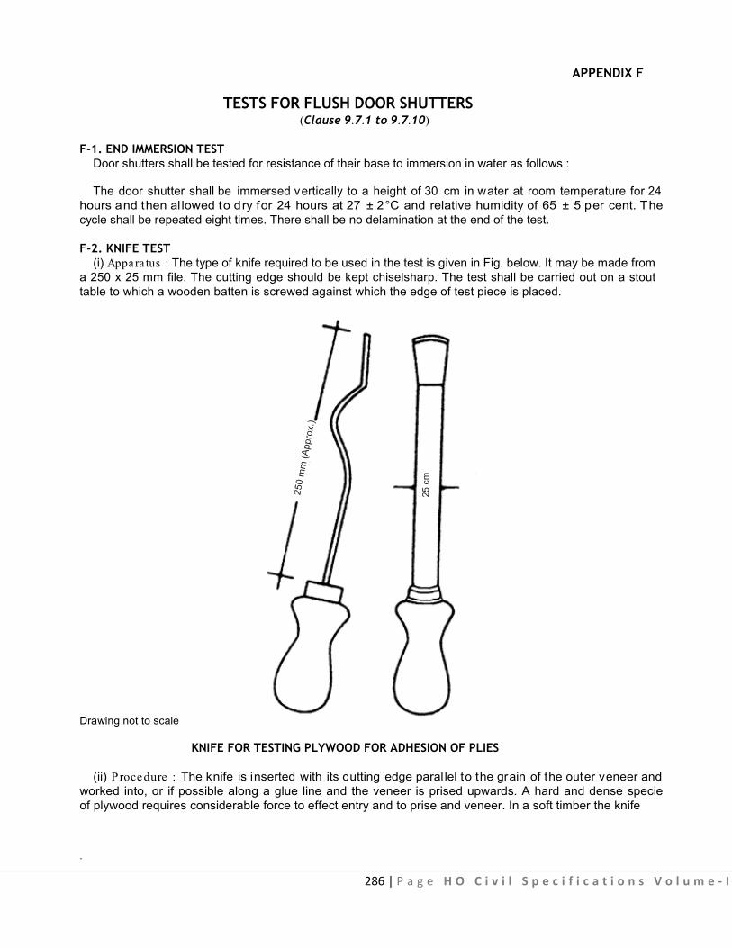
286 | P a g e H O C i v i l S p e c i f i c a t i o n s V o l u m e - I
25 c
m
APPENDIX F
TESTS FOR FLUSH DOOR SHUTTERS (Clause 9.7.1 to 9.7.10)
F-1. END IMMERSION TEST Door shutters shall be tested for resistance of their base to immersion in water as follows :
The door shutter shall be immersed vertically to a height of 30 cm in water at room temperature for 24 hours and then al lowed to dry for 24 hours at 27 ± 2°C and relative humidity of 65 ± 5 per cent. The cycle shall be repeated eight times. There shall be no delamination at the end of the test.
F-2. KNIFE TEST (i) Appara tus : The type of knife required to be used in the test is given in Fig. below. It may be made from
a 250 x 25 mm file. The cutting edge should be kept chiselsharp. The test shall be carried out on a stout table to which a wooden batten is screwed against which the edge of test piece is placed.
Drawing not to scale
KNIFE FOR TESTING PLYWOOD FOR ADHESION OF PLIES
(ii) Procedure : The knife is inserted with its cutting edge paral lel to the grain of the outer veneer and worked into, or if possible along a glue line and the veneer is prised upwards. A hard and dense specie of plywood requires considerable force to effect entry and to prise and veneer. In a soft timber the knife
.

287 | P a g e H O C i v i l S p e c i f i c a t i o n s V o l u m e - I
tends to follow an easy course through the wood and in this case it is essential that the knife be firmly guided along the glue line.
The bond should just pass the requirement, it is judged by the relative amount of wood fibre left on the core veneer, and the area pr ised of f. The grading is assessed chiefly on the appearance of the b reak. The force needed to effect separation is also an accompanying requirement.
The bond is ‘excellent’, when it is difficult to find the glue line and impossible to keep the tool within it for more than 6 mm without cutting adjacent wood. On prising upwards, the veneer usually breaks off over a width slightly greater than that of the tool.
The bond is ‘poor’ when knife meets little opposition in the glue line and the prise results in the easy removal of almost al l the veneers f rom one s ide of the test piece. The separated veneers are usually almost free from adherent fibre.
(iii) Reporting of test results : The results shall be reported as ‘pass standard’ ‘excellent’ or ‘poor’. F-3.
GLUE ADHESION TEST
Four square sections, 150 x 150 mm shall be cut from the corners of the door. These four corner sections as cut from the door shall be i mmersed in boiling water for 4 hou rs, then dried at 27 ± 2°C and relative humidity of 65 ± 5 per cent for 24 hours. At the end of the drying period, the samples shall be examined for delamination. In the case of the glue l ines in the plywood, all the four exposed edges of the plywood on both faces of a specimen shall be examined for delamination.
A specimen shall be considered to have passed the test i f no de lamination has occured in the g lue lines in the plywood and if no single delamination more than 50 mm in length and more than 3 mm in depth has occured in the assembly glue l ines between the plywood faces and the stile and rail. Delamination at the corner shall be measured continuously around the corner. Delamination at a knot, knot hole, a pi tch pocket and worm hole or other permissible wood defects shall not be c onsidered in assessing the sample. A door shall be deemed to have passed this test i f three of the four specimens tested pass the test.

288 | P a g e H O C i v i l S p e c i f i c a t i o n s V o l u m e - I
APPENDIX G
TEST FOR MORTICE LOCKS (Clause 9.15.13)
The finally assembled lock shall withstand the test given as below :
The locking bolt shall be f irst locked in the forward position. A load of 40 kg. shall be appl ied without
shock in the direction perpendicular to securing face as well as on both the locking faces of protruding bolt in turn. Then the load shall be applied by means of a f ixed steel board 3 mm thick by rounded edge held in such a position that the centre line is approximately 3 mm from the fore end. A typical arrangement for the purpose of this test is shown in Fig. below :
Beam 75 c m Long Approx
Lock
Base
Fixed Bearer
Fixed Block
Steel Bar 75 cm Long Approx.
Movable Weight 40 kg
Fig. : Strength Test for Locking Bolt
When the spindle with handle is inserted into hole in the follower and turned, the latch bolt shall draw smoothly into the lock body and shall be within one millimetre from the face of the fore end.
When the latch bolt is pressed in to the lock body by pressure, the action shall be smooth and when fully pressed the latch bolt shall not project more than one millimetre from the face of the fore end.
When a k ey is inserted in key hole from one side of the lock and turned to withdraw the locking bolt the action shall be s mooth and w ithout impediment. When the direction of turn is reversed to lock the locking bolt then also the action shall be smooth and without impediment. In the locked position the locking bolt shall project 12 mm from the face of the fore end, although one millimetre free movement is permissible. I n the withdrawn pos ition t he locking bo lt s hall not p roject more than one millimetre from the face of the fore end. The locking bolt shall be worked by turning key in both the direction 6000 times. At the end of the test, the lock shall continue to work smoothly.
The test shall be repeated with the key inserted from the other side of the lock.
Note : The clearance for levers while in the operating condition shall not exceed 0.25 mm.
When the key is turned to lock the locking bolt at the same time applying a reasonable pressure by finger on it, after completion of the key rotation the locking bolt shall be positively locked in the forward position. This test shall be repeated with the key inserted from the other side of the lock.

289 | P a g e H O C i v i l S p e c i f i c a t i o n s V o l u m e - I
APPENDIX H
SCHEDULE OF FITTING FOR DOORS AND WINDOWS (Clause 9.6.8)
S l. Name o f Fittings Double S ingle S ingle S ingle S ingle S ingle Fan Des i- Length Remarks No leaf leaf door leaf door leaf leaf leaf light/ gna- in mm
doors shutters shutters wire wardrobe/ window clear tion of shutters exte rnal inter guaze cup- shutte rs s torey no. of wood pane lled pane lled commu- door board panelled window wood screws
or or glazed nicating shu- shutters or shutters screw IS glazed pane lled tte rs glazed 6760
or glazed 1 2 3 4 5 6 7 8 9 10 11 12
1. Butt Hinges 100 6 3 3 3 - - - 9 40 mm
2 Butt Hinges 75 mm - - - - - 2 2 8 20 3 Butt Hinges 50 mm - - - - 1 1 - 6 20 For fixing
wooden cleat
4 Piano Hinges - - - - - - - 6 20 5 Tower Bolt 250 mm 3 2 3 2 - 1 - 10 30 6 Tower Bolt 150 mm - - - - - 1 - 8 30 7 Tower Bolt 100 mm - - - - - - - 6 30 8 Sliding door Bolt 1 - - - - - - 9 35
300 mm 9 Sliding door Bolt - 1 - - - - - 9 35
250 mm 10 Floor door stopper 2 1 1 - 1 - - 9 30 11 Door handle with 2 2 2 1 - - - 6 25
plate 100 mm 12 Window handle with - - - - - 1 - 6 20
plate 75 mm 13 Casement stay 300 - - - - - 1 - 6 30
mm 14 Helical door spring - - - 1 - - - 6 30
(Superior quality) 15 Cupboard - - - 1 1 - - 6 20
/Wardrobe Lock 16 Fanlight Catch - - - - - - 1 8 30 Notes :
A : Door Shutters 1. Door of room adjoining the verandah, corridor, lobby or hall, shall be considered as external door. 2. Where the height of the door leaf exceeds 2.15 metres above the floor level, one extra hinge shall be provided for every additional height of 0.50 metre, or part thereof and the length of top bolts shall be increased by the height of the leaf above 2.15 metres from floor level. 3. Single leaf door shutters of more than 0.80 m in width shall be provided with one extra hinge. 4. Fan light shutters of more than 0.80 metre width shall be provided with one extra hinge and extra quadrant stay. 5. In double leaf shutters of doors, two door bolts shall be fixed to the first shutter and one to the closing shutter at the top. 6. In case of single leaf inter communicating, panelled, glazed or panelled door shutter for bath and w.c. one tower bolts will be replaced by a bathroom latch. 7. For shutter exceeding 40 mm thickness, heavy type M.S. butt hinges of 125 x 90 x 4 mm shall be used. 8. In case of external door shutters, instead of sliding door ball mortice lock can be provided where specified. 9. Cupboard and wardrobe shutters will have ball catches where specified.
10. Finger plates shall be provided in case of bath and wc shutters in office buildings.
B : Window Shutters 11. In case of windows with double shutters, two tower bolts shall be fixed to the closing shutters and one tower bolt to the first shutter at the top. 12. In case of window shutters, hooks and eyes may be provided in lieu of casement stays where specified. 13. Where the height of window shutter exceeds 1.20 metres one extra hinge shall be provided and length of top bolts shall be increased by height of the leaf above 2.15 metres from the floor level. 14. Window shutter with steel f rames shall be provided with s ix hinges in case of double leaf shutters and three hinges in case of single leaf shutters, irrespective of height and width of shutters.
C : Fanlight and Cleres tory Window or Ventilator 15. Centrally hung and bottom hung CS windows and fan lights, will be provided with chain and hook bamboo pole with hook for opening ventilators shall be provided for each residence or for set of 4 rooms in case of office building. 16. Centrally hung clerestory windows or fan lights will have fan light pivots in lieu of hinges.
.

290 | P a g e H O C i v i l S p e c i f i c a t i o n s V o l u m e - I
APPENDIX I
METHOD OF TEST FOR EDGE STRAIGHTNESS AND SQUARENESS OF PLYWOOD
(Clause No. 9.2.8.3) I.1 PROCEDURE FOR EDGE STRAIGHTNESS I.1.1 The straightness of the edge and ends of plywood shall be verified against a s traight edge not less than the full length of the plywood. If the edge on the end of the plywood is convex, it shall be held against the straight edge i n such a w ay as to give approximately equal gap at each end. T he largest gap between the straight edge and the edge shall be measured to the nearest millimeter and recorded.
I.2 PROCEDURE FOR SQUARENESS
I.2.1 The squareness of plywood shall be c hecked with a 120 0 mm x 1200 mm square by applying one arm of the square to the plywood. The maximum width of the gap shall be recorded.
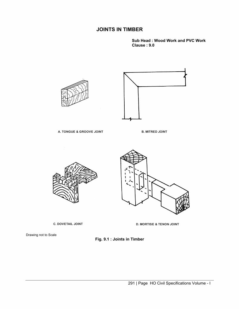
291 | Page HO Civil Specifications Volume - I
JOINTS IN TIMBER
Sub Head : Wood Work and PVC Work Clause : 9.0
A. TONGUE & GROOVE JOINT B. MITRED JOINT
C. DOVETAIL JOINT D. MORTISE & TENON JOINT
Drawing not to Scale
Fig. 9.1 : Joints in Timber

292 | Page HO Specifications Volume - I
TERMINOLOGY TIMBER DOOR, WINDOW & VENTILATOR COMPONENTS
Sub Head : Wood Work and PVC Work Clause : 9.6
Head of Frame
Hold Fast
Glazed PanelDoor Frame
StileMeeting Stile
Lock Rail
Wooden Panel
Bottom Rail
FinishedFloor Level
Metal PinStructural Floor Level
GLAZED AND PANELLED DOOR SQUARE TYPE REBATE
8 to 10 mm
T/2
T/2
SPLAYED TYPEREBATE
T/3
T/3
T/3
8 to 10 mm
DETAILS AT A
Head of Frame
Glass PanelTransome
Hold Fast
Glass PanelStile
Bottom Rail
TOP HUNG VENTILATOR
CENTRE HUNGVENTILATOR
BOTTOM HUNG VENTILATOR
WINDOWS AND VENTILATORS
Top Rail
45°
A
Width of Opening
Drawing not to Scale All dimensions are in mm
Fig. 9.2 : Terminology Timber Door, Window & Ventilator Components

293 | Page HO Civil Specifications Volume - I
WOODEN FLUSH DOORS SHUTTERS
Sub Head : Wood Work and PVC Work Clause : 9.7
TOP RAIL
Lipping Where Provided
Stile
Cross Band
Face Veneer
BLOCK BOARD & PARTICLEBOARD CORE
PARTICLE BOARD CORE
CELLULAR CORE BLOCK BOARD CORE HOLLOW CORE
Battens
EquallyDistributed Voids
Battens
Intermediate Rail
Equally Distributed Voids
Drawing not to Scale
Fig. 9.3 : Wooden Flush Doors Shutters

294 | Page HO Civil Specifications Volume - I
HOLD FAST
Sub Head : Wood Work and PVC Work Clause : 9.13
4020
100 100
200
5
50
Door Frame Hold Fast
Nut & Bolt10 mm dia
C.C. BlockEnlarged Section of Bolt
1510 11 mm Hole
Wooden Plug
50
Drawing not to Scale All dimensions are in mm
Fig. 9.4 : Hold Fast

295 | Page HO Civil Specifications Volume - I
HINGES
Sub Head : Wood Work and PVC Work Clause : 9.15.1 to 9.15.2
A
B
D D
C C
Counter SunkHoles
KnucklesUncranked C ranked
A. DIMENSION OF MEDIUM WT. MILD STEEL BUTT HINGES
Size of Length Breadth Thickness Dai of No. of No. of Screw Holes for Hinge (A) (B) of Flap (C) Hinge Pin (D) Knuckles Holes Screw No. 1 2 3 4 5 6 7 8 50 50 ± 0.5 37 ± 1 1.50 ± 0.06 3.15 ± 0.08 3 4 6 75 75 ± 0.5 47 ± 1 1.70 ± 0.06 4.00 ± 0.08 5 6 8 100 100 ± 0.5 58 ± 1 1.90 ± 0.06 5.60 ± 0.08 5 8 10
Min 7A C
D
Min 7
Min 7
Kunckle
Counter Sunk HoleC
R6
B
B. PARLIAMENT HINGES Drawing not to Scale All dimensions are in mm
Fig. 9.5 : Hinges

296 | Page HO Civil Specifications Volume - I
HINGES
Sub Head : Wood Work and PVC Work Clause : 9.15.5, 9.15.6
D
E
BF
CA
A. T EE HINGES
R
X
G
XX
DIMENSIONS
Size A B C D E F G R Screw Desig- No. of Holes No. of nation No. in Strap Holes in Tee 250 250 ±3 100 ±2 30 ±15 5.6 ±0.10 2.24 ±0.10 45 ±2 40 ±1 8 ±1 9 5 3 300 300 ±3 115 ±2 30 ±1.5 6.30 ±0.10 2.26 ±0.10 50 ±2 50 ±1 8 ±1 9 5 3
B. PIANO HINGES
L2 L1 L1
L1L1L1
1825 ± 5
L3
Min 0.80 Max. 1.0Thick
2.5 mmφ PinB
DIMENSIONS
Nominal Size B L1 L2 L3 40 40 ± 1 25 ± 2 25 ± 1 20 ± 1 30 30 ±1 75 ± 2 25 ± 1 15 ± 1 Drawing not to Scale All dimensions are in mm
Fig. 9.6 : Hinges

297 | Page HO Civil Specifications Volume - I
SLIDING DOOR BOLTS
Sub Head : Wood Work and PVC Work Clause : 9.15.7
250
6.0±5
Bolt
10.0±5 45±1
100±2
40±1
BackPlate
17.5±5φ
3.15
17.5±5 φ
20±12 2.15
60±2
8 mm sq hole for Carriage Bolt
CLIP
8 sq Hole for Carriage Bolt
Bore to be Countersunk
STAPLE
55±1
12±13.15
11±5
40±1
8±.5
MILD STEEL
A
F
E
B
C
CAST TYPE
M
HASP
17.5±5 φ
25±1
27±1
12 sq ±1
12± 0.5φ
50±2
Hex or Sq Nut
Washer
C.I. BOLT
DIMENSIONS
Size A B C E F M Screw Designation No. 250 250 ± 2 100 ± 2 45 ± 1 55 ± 1 15 ± 1 16.0 ± 0.5 9 300 300 ± 2 100 ± 2 45 ± 1 55 ± 1 15 ± 1 16.0 ± 0.5 9 Drawing not to Scale All dimensions are in mm
Fig. 9.7 : Sliding Door Bolts
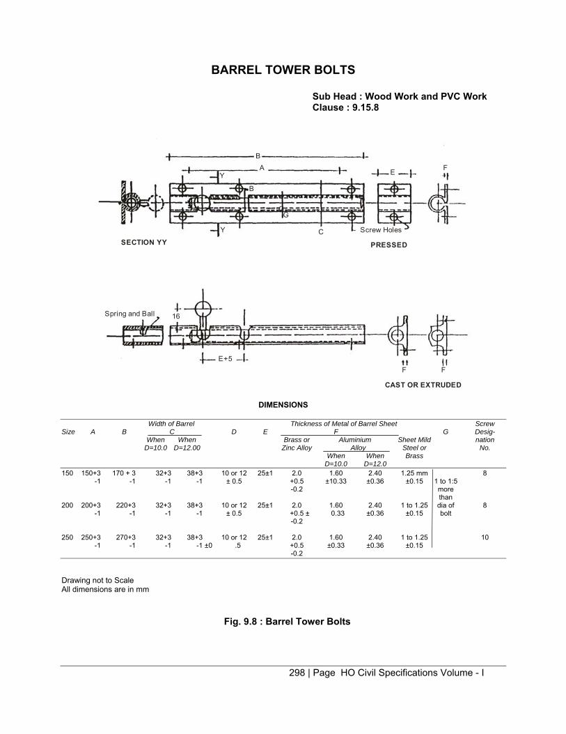
298 | Page HO Civil Specifications Volume - I
BARREL TOWER BOLTS
Sub Head : Wood Work and PVC Work Clause : 9.15.8
SECTION YYY
Y
BA E F
Screw Holes
PRESSED
C
G
B
16Spring and Ball
E+5F F
CAST OR EXTRUDED
G
DIMENSIONS
Width of Barrel Thickness of Metal of Barrel Sheet Screw Size A B C D E F G Desig- When When Brass or Aluminium Sheet Mild nation D=10.0 D=12.00 Zinc Alloy Alloy Steel or No. When When Brass D=10.0 D=12.0 150 150+3 170 + 3 32+3 38+3 10 or 12 25±1 2.0 1.60 2.40 1.25 mm 8 -1 -1 -1 -1 ± 0.5 +0.5 ±10.33 ±0.36 ±0.15 1 to 1:5 -0.2 more than 200 200+3 220+3 32+3 38+3 10 or 12 25±1 2.0 1.60 2.40 1 to 1.25 dia of 8 -1 -1 -1 -1 ± 0.5 +0.5 ± 0.33 ±0.36 ±0.15 bolt -0.2 250 250+3 270+3 32+3 38+3 10 or 12 25±1 2.0 1.60 2.40 1 to 1.25 10 -1 -1 -1 -1 ±0 .5 +0.5 ±0.33 ±0.36 ±0.15 -0.2 Drawing not to Scale All dimensions are in mm
Fig. 9.8 : Barrel Tower Bolts

299 | Page HO Civil Specifications Volume - I
PULL BOLT LOCKS
Sub Head : Wood Work and PVC Work Clause : 9.15.10
Guide and 10 mm Plate 3 mm Thick 8 mm Round Head with Square Seal Door Frame Shutter
6 mm Round Head Nutwith Square Seat
Slide and Stop Block
Iron Screw
Open Position
PLAN
ELEVATION 10 mm Dia bolt in Locking Position
Drawing not to Scale
Fig. 9.9 : Pull Bolt Locks

300 | Page HO Civil Specifications Volume - I
MORTICE LOCK & LATCH
Sub Head : Wood Work and PVC Work Clause : 9.15.13 Locking Bolt Guide Pin
18
7
6
23
5
4
12 Min
100 ±1
Lever SpringFulorum Pin
Latch SpringPivot Pin
Lever Pivot Pin 1 Body Locking Bolt Body Cover
Size of LockOptional
ASSEMBLED WITHOUT BODY COVER
25 25 Striking Plate
2 Case Plate3 Face PlateOptional
5 Locking Bolt
8 mm Square Holefor Connecting Rod
Key8 Follower7 Latch Spring6 Lever
Locking Pin
25
16
12
4 Latch Bolt
5.5+2-0
25
Alternative Fixture for Face Plate
Drawing not to Scale All dimensions are in mm
Fig. 9.10 : Mortice Lock & Latch

301 | Page HO Civil Specifications Volume - I
MORTICE NIGHT LATCH
Sub Head : Wood Work and PVC Work Clause : 9.15.16
Nominal Size (L)
Face Plate(Optional)
Case PlateBodySpring
Fore EndRight Latch
Locking Bolt
LeversFollower
1 2
7 3
45
100
1.25 min
ASSEMBLY WITHOUTBODY COVER
BODY BODY COVER
Square Hole
2 Follower
3 Latch Spring
SquareHole
10
6 Latch Bolt
5 Locking Lug
4 Lever7 Locking Bolt
15 min
1 CASE PLATE
25
8
6
3
25
Drawing not to Scale All dimensions are in mm
Fig. 9.11 : Mortice Night Latch

302 | Page HO Civil Specifications Volume - I
HANDLES FOR DOORS AND WINDOWS
Sub Head : Wood Work and PVC Work Clause : 9.15.19
F
C
B
D
F
A
G
1A
E
D
B
1B
A
G
F
Fig. 9.12.1 : Typical Door Handle (Type 1)
C
B
H G
F
E E
F
Fig. 9.12.2 : Typical Door Handle (Type 2)
X
X
E
C
B
A
F
R33
0.75
SECTION XX
Fig. 9.12.3 : Typical Door Handle (Type 3)
H G
C
E
D
B
A
FixingArrangement
Continuous Plate may be Provided where desired
G
Note : M5 x 20 mm G.I. Countersunk machine screw or any other suitable fixing arrangement may be used
Fig. 9.12.4 : Typical Door Handle (Type 4) Drawing not to Scale All dimensions are in mm
Fig. 9.12 : Handles for Doors and Windows

303 | P a g e H O C i v i l S p e c i f i c a t i o n s V o l u m e - I
TABLE 2A DIMENSIONS OF DOOR HANDLES
(Fig. 9.12.1 to 9.12.3) All dimensions in millimetres
Type Re f to. S izes A B C D E F G H I Screw Holes* of Fig. Min Min Min Min Min Min Min Min No. in Size Des ignation of
Head Each Counter-sunk Head Lug Wood Screw (see
IS 6760-1972#)
(1) (2) (3) (4) (5) (6) (7) (8) (9) (10) (11) (12) (13) (14)
9.12.1A 75 125 75 20 2.5 5 8 15 - - 2 6 100 150 100 25 3.0 8 10 20 - - 2 6 125 190 125 25 4.0 10 12 22 - - 2 6 150 215 150 30 1.5 12 15 25 - - 2 8
1. 9.12.1B 75 85 75 20 2.5 5 8 15 - - 2 6
100 110 100 25 3.0 5 10 20 - - 2 6 125 140 125 25 3.0 7.5 12 22 - - 2 6 150 165 150 30 4.0 7.5 15 25 - - 2 8
2. 9.12.2 75 125 75 20 - 10 16 32 20 1.0 2 6 100 150 100 25 - 11 19 38 20 1.0 2 6 115 175 115 28 - 13 22 45 25 1.0 3 8 135 200 135 30 - 14 25 50 32 1.25 3 8
3. 9.12.3 75 100 75 20 - 5 14 16 8 1.25 1 6 90 125 90 25 - 6 16 20 10 1.25 2 6
100 150 100 28 - 7 18 25 12 1.60 2 6 * More evenly spaced screw holes may be provided, if so required by the purchaser. # Specification for slotted countersunk head wood screws.
TABLE 2B DIMENSIONS OF DOOR HANDLES All dimensions in millimetres.
Type Ref to S izes A B C D E# G Screw H oles**
Fig. Min Min Dia No. in No. in a S ize Designation of Each plate when Counter-sunk Head Lug a continuous Wood Screws (see
P late is used IS : 6760-1972$)
(1) (2) (3) (4) (5) (6) (7) (8) (9) (10) (11) (12)
30 + 0 4 9.12.4 75 115 75 25 5 ± 0.5 10 ± 0.5 30 + 0 2 4 6
30 - 1 30 + 0
100 140 100 30 5 ± 0.5 10 ± 0.5 30 + 0 2 4 6 30 - 1
30 + 0 125 175 125 35 5 ± 0.5 12 ± 0.5 38 + 0 3 6 6
30 - 1
30 + 0 150 200 150 35 5 ± 0.5 12 ± 0.5 38 + 0 3 6 6
30 - 1 In case a continuous base plate is used, the thickness may be reduced to 3 mm.
# Hexagonal or round. ** More evenly placed screw holes may be provided, if so required by the purchaser. $ Specification for slotted countersunk head wood screws.
.

304 | Page HO Civil Specifications Volume - I
FLOOR DOOR STOPPER - CAST TYPE
Sub Head : Wood Work and PVC Work Clause : 9.15.20
B12.5
C ARubberPiece 16
Body or Housing
8 Pinφ 32 2
185
Cover PlateSpring
45R
4016
20
12.5
25
T1
DIMENSION
Thickness of A B C Casting Screw No. of Holes Door Shutter T1 Designation No. for T1 30 35.0 ± 0.5 140.0 ± 0.5 13 4.5 + 0.3 9 4 -0 35 40.0 ± 0.5 140.0 ± 0.5 8 4.5 ± 0.3 9 4 -0 40 45.0 ± 0.5 150.0 ± 0.5 13 4.5 + 0.3 9 4 - 0 45 50.0 ± 0.5 150.0 ± 0.5 8 4.5 + 0.3 9 4 - 0
Drawing not to Scale All dimensions are in mm
Fig. 9.13 : Floor Door Stopper – Cast Type
WINDOW STAY
Sub Head : Wood Work and PVC Work Clause : 9.15.23
7380 mm to Web
22
8 mm dia Pin18
300Locking Bracket
75656575
30
Drawing not to Scale All dimensions are in mm
Fig. 9.14 : Window Stay

305 | P a g e H O C i v i l S p e c i f i c a t i o n s V o l u m e - I
HASP & STAPLES Sub H ead : Wood Work a nd P VC Work Clause : 9.15.25
Install Thus
T
T for mild Steel Sheet T1for Cast or Extruded Section of Brass
F
¼B
½B
¼B d D1
HASP (Mild Steel or Brass)
MILD S TEEL Size A B C D
90 90±2 38±1.5 46±2 5.0± .10 115 115±2 38±1.5 46±2 5.0± .10 150 150±2 45±1.5 60±2 6.30± .10
A
G
E
H
H f or Mild Steel Sheet H' for Cast o r Extruded Section or Brass
E F G H J 5.0± .5 35±1.5 28±1.5 8±.5 12±1 5.0± .5 55±1.5 28±1.5 8±.5 12±1 6.0± .5 65±1.5 33±.5 10±.5 15±1
B
C Staple ( Mild S teel) D+18
STAPLE (Brass or Aluminium)
Thick- ness of Sheet
K R T 8±1 8±.5 2± .10 8±1 8±.5 2± .10 14±1 9±.5 2.24± .10
K
D
R
T1
D+1.5
R
K T2
Dia of Screw Holes Hinge No. on No. on Screw Pin d Hasp Staple Desig-
nation No.
4± .10 3 4 8 4± .10 3 4 8 5± .10 4 4 10
BRASS CAST OR EXTRUDED Thick- Dia of Dia of Screw Holes
Ness Hinge Butt No. on No. on Screw Pin d D1 Hasp Staple Desig-
nation No.
Size A B C D E F G H K R T1 T2
90 90±2 40±1.5 42±1.5 5±.25 6±.5 35±1 28±.5 10±.5 8±1 6.5±.5 2±.25 3±.25 3.15±.10 6±.2 3 4 5 115 115±2 40±1.5 42±1.5 5±.25 6±.5 45±1 28±.5 10±.5 11±1 6.5±.5 2±.25 3±.25 3.15±.10 6±.2 3 4 8 150 150±2 46±1.5 48±1.5 6±.25 7±.5 65±1 32±.5 11±.5 14±1 7.5±.5 3±.25 4±.25 4±.10 8±.2 4 4 0
Drawing not to Scale All dimensions are in mm
Fig. 9.15 : Hasp & Staples
.

306 | Page HO Civil Specifications Volume - I
LVL SHUTTER
Sub Head : Wood Work and PVC Work Clause : 9.16.6
100Top Rail
Stile
12 mm thick Rubber WoodLipping Alround
100
mm
Lon
g H
inge
s
Lock Rail 150
100PANEL100
Beading for fixing Panel
Cen
ter L
ine
of L
ock
Rai
l
850
200BOTTOM RAIL
PANEL
Beading for Fixing Panel
1/3 t
2/3t
t
All Dimension are in mm
Fig. 9.16 : Typical Illustratino of Panelled LVL Door Shutter
Fig. 9.16A : Single Tenon Joint
25 mm
65 mm
20 mm
25 mm
65 mm
200 mm
Fig. 9.16B : Double Tenon Joint
Fig. 9.16C : Common Methods of Joining Panel with Stiles and Rails with/
without Beading
Fig. 9.16D : Meeting of Stiles for DoubleLeaved Door Shutters
0 to 10 mm 0 to 10 mm
1/3
1/3
1/31/2
1/2
A - Splayed Type B - Square Type
Fig. 9.16 : LVL Shutter

307 | P a g e H O C i v i l S p e c i f i c a t i o n s V o l u m e - I
Stu
d at
610
mm
c/c
PARTITIONS Sub H ead : Wood W ork a nd P VC Work Clause : 9.17.2
Fillet Ceiling Channel
Board Fillet
Metal Stud at 610 mm Centres Calcium Silicate Board
Skirting
Floor Channel
Skirting ELEVATION
Floor and Ceiling Channel ISOMETRIC VIEW
WALL AND E ND DETAIL
610 CORNER DETAIL T-JUNCTION
PLAN
DETAILS
Board 8 / 10 / 12 mm Thick One layer board on each side of studs Board Fillets 60 / 100 mm On each side of all studs and channels Floor/Ceiling Channel 50 x 32 x 32 x 0.55 mm Top and bottom perimeter of the partition Stud 48 x 50 x 48 x 0.55 mm Vertically at 610 mm c/c Bracing Member 45 x 15 x 15 x 0.9 mm At horizontal board joint on both side Screws (C/S head) 25 & 35 mm long, self 12 mm from the edge & 40 mm from the
drilling with under head cutter corner of the board at 200 mm c/c
Fig. 9.17 : Partitions

308 | Page HO Civil Specifications Volume - I
PVC DOOR FRAME
Sub Head : Wood Work and PVC Work Clause : 9.20.1
150mm Long 'L'Shape Brakcet 15 mmx 15 mm sq. Tube 19 Gauge inserted into
19 x 19 mm M.S. Square Tube of
19 Guage
Solid PVCChoukhat
Hinge
75 mm Long M.S.Screws fixed with
PVC Fasteners forFixing Frame to Wall
ELEVATION (Scale - 1 : 25)
EBottom Rail
D Lock Rail
Top RailC
15 m
m
Lock Rail(Upper)(Detail at 'H')
Panel
Lock Rail(Lower)
100
mm
DETAIL AT 'D'(Scale - 1:3)
50 mm
5 mm
5 mm
EDPM Rubber Gasket
19 mm x 19 mm M.S.Square Tube
5 mm
40 mm
30 m
m
Section View of Solid PVC Choukhat
75 mm
100
mm
25 m
m
Detail at 'F'PVC 'C' Channel
30 mm
25 m
m
25 mm
100
mm
25 mm 30 mm
Detail at 'H'PVC Bottom Rail
Detail at 'G'PVC 'C' Channel
25 m
m
47
50 mm
Gap insertfor Top15 mm x 15 mm M.S. Square TubeTop Rail(Detail at -G)
Gap insertbelow Top Rail
PVC Beading
5 mm PVC Panel
5 mm PVC Panel
PVC Beading
Gap insert below bottom Rail
Bottom Rail(Detail at - H)
15 mm x 15 mmM.S. Square Tube
Gap insertfor bottom
Detail at 'E'(Scale - 1:3)
Detail at 'C'(Scale - 1 : 3)
50 mm
Solid PVC Choukhat
47 m
m
40 mm Hinge 5 mm PVC'C' Channel(Detail at 'F')
5 mm PVC Panel
5 mm PVCBeading
19 mm M.S. Square Tube
75 mm
5 mm PVCBeading
19 mm M.S.Square Tube
Solid PVCChoukhat
50 mm75 mm
40 mm5 mm PVC'C' Channel
(Detail at 'F')Detail at 'A'(Scale - 1 :3)
Detail at 'B'(Scale - 1 :3)
A B
15 m
m
47 m
m
15 m
m
100
mm
100
mm
Fig. 9.21 : PVC Door Frame

309 | Page HO Civil Specifications Volume - I
30 mm THICK PANEL PVC DOOR SHUTTER
Sub Head : Wood Work and PVC Work Clause : 9.21.1(a)
B
B
C
C
150 mm Long'L' Shape Bracket
Top Rail
Stiles
Beading
19 mm M.S. Square Tube
Hinge
Lock Rail
75 mm LongSteel Screws
Panel
PVC Choukhat
Bottom Rail
15 mm M.S. Square Tube
5 mm PVC Panel
7 mm (5+2)PVC Beading
Taper Plain Top Rail
15 mm x 15 mm M.S. Square Tube
Gap insert for Top
50 m
m
47 mm
Plain Solid PVCChoukhat
47 m
m
50 mm
40 mmHinge
5 mm TaperPlain
5 mm PVC Sheet
7 mm (5 mm + 2 mm PVC Beading)
19 mm x 19 mm M.S,Square Tube
75 mm
PVC 'C' Channel
(Sectional View 'AA')
ELEVATION
(Sectional View 'BB') (Sectional View 'CC')
Tapper Lock Rail (Upper)
5 mm Both Side PrelamPVC Panel
7 mm (5mm + 2 mm)Lock Rail (Lower)A A
Fig. 9.22 : 30 mm Thick Panel PVC Door Shutter

310 | Page HO Civil Specifications Volume - I
SKETCH ILLUSTRATING DIMENSIONS OF SHUTTER
Sub Head : Wood Work and PVC Work Clause : 9.23.1
45 mm
3 mm
Thickness of DoorFrame - Rebate = 45 mm
5 mmClearance
5 mm Clearance
M
= M
odul
ar H
eigh
t of
Doo
r Ope
ning
M -
10
mm
= O
vera
ll H
eigh
t of
Doo
r Fra
me
H
H
M -
95
mm
= H
eigh
t of S
hutte
r H
M - 100 mm = Width of Shutter
w
M - 10 mm = Overall Width of Door Frame
w
M = Modular Width of Door Opening
w
Structural Floor Level
40 mm
Finished Floor Level
Fig. 9.24B : Sketch Illustrating Dimensions of Shutter

311 | Page HO Civil Specifications Volume - I
SINGLE REBATE DOOR FRAME
Sub Head : Wood Work and PVC Work Clause : 9.24.1
750
230
Panel Door
Door Frame(60 mm x 30 mm)
FRONT ELEVATION
INSIDE
OUTSIDE690
750
100
PLAN
Fisher Screw
Door Frame (60 mm x 30 mm)
40 x 20 M.S. Pipe
PVC Foam Profile
3 mm Thick HPL Sheet
Beading Profile
60
30 30
30 228
PVC Foam Profile
Typical Door Frame Detail (60 mm x 30 mm)
DETAIL - X
2100
X
Drawing not to scale Al dimensions are in mm
Fig. 9.25 : Solid PVC Foam Profile Frame

Perimeter Channel
WALL PANELLING
Sub Head : Wood Work and PVC Work Clause : 9.27
Perimeter Channel
Calcium Silicate Board
Ceiling Section
Calcium Silicate Board
Vertical M/F Ceiling Section Wall
Skirting
Perimeter Channel Fixed to the Soffit and floor
FRAME & BOARDING ARRANGEMENT
Fig. 9.28 : Wall Panelling
312 | Page HO Specifications Civil Volume - I
ELEVATION
313 | P a g e H O C i v i l S p e c i f i c a t i o n s V o l u m e - I
10.0: Steel Work

314 | P a g e H O C i v i l S p e c i f i c a t i o n s V o l u m e - I
CONTENTS
Clause No. Description Page No.
List of Mandatory Tests 316
List of Bureau of Indian Standards Codes 317 10.0 Definitions/Terminology 318 10.1 Materials 318 10.2 Steel Work in Single Section Fixed Independently with Connecting Plate 320 10.3 Steel Work in Built up Section (Riveted and Bolted) 321 10.4 Steel Work in Built up Section (Welded) 325 10.5 Collapsible Steel Gates 326 10.6 M.S. Sheet Sliding Shutter - DELETED 327 10.7 M.S. Sheet Shutters - DELETED 327 10.8 Rolling Shutters 327 10.9 Rolling Grills -Shutters 329 10.10 Steel Doors, Windows, Ventilators & Composite Units - DELETED 329 10.11 T-Iron Doors, Windows & Ventilators Frames - DELETED 329 10.12 Pressed Steel Door Frames - DELETED 329 10.13 Tubular Hollow Section Trusses - DELETED 329 10.14 Fan Clamps 329 10.15 M.S. Hollow Rectangular Door Frames (I-Type Section) - DELETED 330 10.16 Factory Made Glazed Steel Doors, Windows and Ventilators - DELETED 330 10.17 Steel Work for Staircases, Chequred Plate, Grating, Ladder, Railings, 330
Bracket and Gate etc. 10.18 Steel Work for Hand Rails 330

315 | P a g e H O C i v i l S p e c i f i c a t i o n s V o l u m e - I
Appendix A Mechanical Properties and Chemical Composition of Steel 331 Appendix B Welding Process 334 Appendix C Steel Tubes for Structural Purposes 335 Appendix D Shapes, Weights and Designation of M S Rolled Steel Section 336 Fig. 10.1 Welds and Rivets 339 Fig. 10.2 Collapsible Steel Gate 340 Fig. 10.3 Typical M.S. Sheet Shutters - DELETED - Fig. 10.4, Doors, Windows and Ventilators - DELETED - 10.5 & 10.6 Fig. 10.7 Fixing Butt Hinges to T-Iron Frame - DELETED - Fig. 10.8 Pressed Steel Door & Window Frames - DELETED - Fig. 10.9 Fan Clamps 341
.
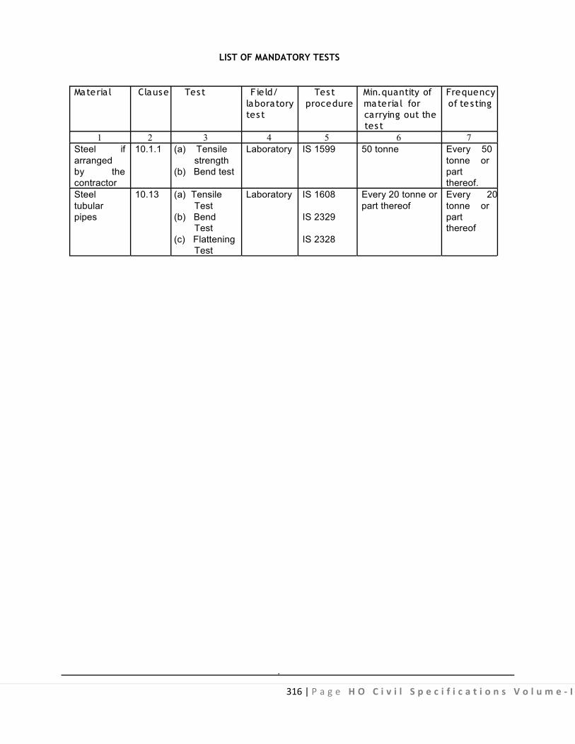
316 | P a g e H O C i v i l S p e c i f i c a t i o n s V o l u m e - I
LIST OF MANDATORY TESTS
Materia l Clause Tes t F ie ld/ Tes t Min.quantity of Frequency
laboratory procedure materia l for of te sting tes t carrying out the
tes t 1 2 3 4 5 6 7
Steel if 10.1.1 (a) Tensile Laboratory IS 1599 50 tonne Every 50 arranged strength tonne or by the (b) Bend test part contractor thereof. Steel 10.13 (a) Tensile Laboratory IS 1608 Every 20 tonne or Every 20 tubular Test part thereof tonne or pipes (b) Bend IS 2329 part
Test thereof (c) Flattening IS 2328
Test .

317 | P a g e H O C i v i l S p e c i f i c a t i o n s V o l u m e - I
LIST OF BUREAU OF INDIAN STANDARDS CODES
S l. Code No. Subject No. 1 IS 63 Whiting for paints and putty 2 IS 198 Varnish gold size 3 IS 228 Structural steel (Standard quality) 4 IS 277 Specification for galvanized steel sheets (Plain and corrugated) 5 IS 800 Code of practice for use of structural steel in general in steel construction 6 IS 806 Code of practice for use of steel Tubes in general building construction 7. IS 808 Dimensions for Hot rolled steel beams, columns, channel and angle
sections 8. IS 812 Glossary of terms relating to welding and cutting metals 9. IS 813 Scheme of symbols for welding 10 IS 814 Covered electrodes for manual metal arc welding of carbon and carbon
manganese steel 11 IS 816 Code of practice for use of metal arc welding for general construction in
mild steel 12 IS 817 Code of practice for training and testing of metal arc welders 13 IS 818 Code of practice for safety and healthy requirements in electric and gas
welding and cutting operations 14 IS 822 Code of procedure for inspection of welds 15 IS 823 Manual for metal arc welding in mild steel 16 IS 1038 Steel doors, windows and ventilators 17 IS 1081 Code of practice for fixing and glazing of metal (Steel and aluminium)
doors, windows and ventilators 18 IS 1148 Hot rolled steel rivet bars (upto 40 mm diameters) for structural purposes 19 IS 1161 Steel tubes for structural purposes 20 IS 1182 Recommended practice for radiographic examination of fusion welded butt
joints in steel plates 21 IS 1200- (Pt. VIII) Method of measurements of steel work and iron works 22 IS 1363 Part I Haxagon head bolts, screws, and nuts of product grade C (Hexagon Head
bolt) 23 IS 1363 Part II Haxagon Head Bolts, screws and nuts of product Grade ‘C’ 24 IS 1363 Part-III Haxagan Head Bolts, screws and Nuts of product grade ‘C’ 25 IS 1367 Technical supply conditions for threaded steel fasteners 26 IS 1599 Method for bend test 27 IS 1608 Metallic materials - Tensile Testing at Ambient Temperature. 28 IS 1821 Dimensions for clearance holes for bolts and screws 29 IS 1852 Rolling and cutting tolerance for hot rolled steel products 30 IS 1894 Method for tensile testing of steel tubes 31 IS 1977 Structural steel (ordinary quality) 32 IS 2062 Hot Rolled low, medium and high tensile structural steel 33 IS 2074 Ready mixed paint, air drying redoxide zinc chrome priming 34 IS 4351 Specification for steel door frames 35 IS 4454 (Part I) Steel wires for mechanical springs. Cold drawn unalloyed steel wire. 36 IS 4711 Methods for sampling of steel pipes, tube and fittings. 37 IS 4736 Hot - dip zinc coating on mild steel tubes 38 IS 4923 Hollow Steel Sections for Structural Use - Specification 39 IS 6248 Metal rolling shutters and rolling grills 40 IS 7452 Specification for hot rolled steel sections for doors, windows and
ventilators.
.

318 | P a g e H O C i v i l S p e c i f i c a t i o n s V o l u m e - I
10.0 STEEL WORK 10.0 DEFINITIONS/ TERMINOLOGY
Bead A single run of weld metal deposited on surface.
Butt Weld A weld in which the weld metal lies substantially within the extension of the planes arc the surfaces on
the parts joined.
Crater A depression left in weld metal where the arc was broken or the flame was removed.
End Crater A crater at the end of a weld or at the end of a joint.
Fillet Weld
A weld of a pproximately triangular cross-section join ing two surfaces approximately at th e right angles to each other in a lap joint, tee joint or corner joint. It is of two types:
(1) Continuous (2) Intermittent.
Fusion Welding
Any welding process in which the weld is made between metals in a state of fusion without hammering or pressure.
Non- fusion Welding A term appl ied to the deposition, by the Oxy-Acetylene process of f iller metal on parent metal without
fusion of the latter.
Oxy-Acetylene Pressure Welding Pressure welding in which any Oxy-Acetylene flame is used to make the surface to be united plastic. No
filler metal is used.
Run The metal deposited during one passage of the electrode or blow pipe in the making of a joint.
Throat thickness See Fig. 10.1.
Weld A union between two pieces of metal at faces rendered plastic or l iquid by heat or pre ssure, or bot h,
Filler metal may be used to effect the union.
10.1 MATERIALS
Micro-Alloying Elements Elements such as niobium, boron, vanadium and t itanium added singly or in combination to obtain
higher strength to weight ratio and better toughness, formability and weldability as compared to unalloyed steel of similar strength level.

319 | P a g e H O C i v i l S p e c i f i c a t i o n s V o l u m e - I
Weldability
A metallic substance i s considered to be w eldable by a gi ven process and for the given purpose, when metallic continuity to a stated degree can be obtained by welding using a suitable procedure, so that the joints comply with the requirements specified in regard to both their local properties and t heir influence on the construction of which they form a part.
Controlled Rolling A hot rolling p rocess in which the temperature of the s teel and its reduction ratio are controlled,
particularly dur ing the f inal rolling passes, in order to achieve f ine grain m icro s tructure and opt imum mechanical properties. Normalizing Rolling
A hot rolling process in which the final rolling passes are carried out at a suitable higher temperature, followed by cooling i n natural ai r to a t emperature below t he t ransformation temperature, i n order t o produce a structure, analogous to that obtained by a separate normalizing treatment of hot rolled product.
10.1.1 Steel 10.1.1.1 Supply of Material : General requirements relating to supply of structural steel shall conform to IS 8910.
10.1.1.2 Grades : There shall be ni ne grades of steel as given in Tables 10.1 and 10. 2. W hile placing the order the steel should be designated by ‘Designation’ (See Table 10.1 and 10.2).
10.1.1.3 Manufacture : The processes used in the steel making and further hot rolling into steel plates, strips, sections, flats, bars, et c., are left to t he discretion o f the manufacturer/supplier. If r equired, secondary r efining m ay follow steel m aking, a s a lso no rmalizing r olling/controlled ro lling du ring manufacturing of sections or as per the agreement between the purchaser and the manufacturer/ supplier.
10.1.1.4 Freedom from Defects 10.1.1.4.1 All finished materials shall be well and cleanly rolled to the dimensions, sections and masses s pecified. T he f inished m aterial s hall be r easonably f ree f rom s urface f laws; laminations; rough/ jagged and imperfect edges and all other harmful defects.
10.1.1.4.2 Minor surface defects may be removed by the manufacturer/supplier by grinding provided the thickness i s not reduced locally by m ore than 4 pe rcent below t he m inimum specified thickness. Reduction in thickness by gr inding greater than 4 percent but not exceeding 7 per cent may be m ade subject to mutual agreement between the purchaser and manufacturer/supplier.
10.1.1.4.3 Subject to agreement with the purchaser, surface defects which cannot be dealt with as in 10.1.1.4.2 may be repaired by chipping or grinding followed by welding and inspection by a mutually agreed procedure such that :
(a) After complete removal of the defects and before welding, the thickness of the item is not to be reduced by more than 20 percent at any place. (b) Welding is carried out by procedure APPROVED by competent authority with approved electrodes and the welding is ground smooth to the correct nominal thickness; and (c) S ubsequent to the finish grinding, the item may be req uired to be n ormalized or ot herwise heat- treated at the purchaser’s discretion.
10.1.1.4.4 Welding as mentioned in 10.1.1.4.3 is not permissible for grade designation E 250 material.

320 | P a g e H O C i v i l S p e c i f i c a t i o n s V o l u m e - I
10.1.1.5 Chemical Composition : Ladle Analysis the ladle analysis of the steel, when carried out by the method specified in the relevant part o f IS 228 or any other established instrumental /chemical method, shall be as given in Table 10.1. In case of dispute, the procedure given in IS 228 and its relevant parts shall be the referee method and where test methods are not specified shall be as agreed to between the purchaser and the manufacturer/supplier.
10.1.2 Rivets Rivets shall be made from rivet bars of mild steel as per IS 1148.
10.1.3 Bolts These are of two types namely turned and fi tted bol ts and black bolts. Turned & fi tted bolts are
turned to exact d iameter i n automatic lathe. For these bol ts, whether reamed or dri lled bolts, the same unit s tresses are al lowed as for r ivets. In case of black bol ts which are not finished to exact sizes, a lower working s tress other than for turned bolts is adopted. They shall conform to IS 1367 - Technical supply conditions for threaded steel fasteners.
10.1.4 Electrodes The e lectrodes r equired f or m etal ar c w elding s hall be c overed e lectrodes and s hall c onform to
IS 814.
10.2 STEEL WORK IN SINGLE SECTION FIXED INDEPENDENTLY WITH CONNECTING PLATE
10.2.0 The steel work in single section of R.S. joists, f lats, Tees Angles f ixed independently with or without connecting plate, is described in these clauses.
10.2.1 Fabrication The steel sections as specified shall be straightened and cut square to correct lengths and measured with
a steel tape. The cut end s ex posed to v iew s hall be finished s mooth. N o two pi eces shall be w elded or otherwise jointed to make up the required length of member.
All straightening and shaping to form, shall be done by pressure. Bending or cutting shall be carried out in such a manner as not to impair the strength of the metal.
10.2.2 Painting All surfaces which are to be painted, oiled or otherwise treated shall be dry and thoroughly cleaned to
remove all loose scale and loose rust. Surfaces not in contact but inaccessible after shop assembly, shall receive the full specified protective treatment before assembly. This does not apply to the interior of sealed hollow sections. Part to be encased in concrete shall not be painted or oiled. A priming coat of approved steel primer such as Red Oxide/Zinc Chromate primer conforming to IS 2074 shall be applied before any member of steel structure are placed in position or taken out of workshop.
10.2.3 Erection Steel w ork s hall be h oisted a nd pl aced in p osition carefully w ithout any da mage to itself and other
building work and injury to workmen. Where necessary mechanical appliances such as lifting tackle winch etc. shall be used. The suitability and capacity of all plant and equipment used for erection shall be upto the satisfaction of the Engineer-in-charge.
10.2.4 Measurements The work as f ixed in place shall be m easured in running metres correct to a millimetre and weights
calculated on t he bas is of s tandard tables correct to the nearest k ilogram. The standard weight of s teel sections shall conform to IS 808 w ith tolerance in s izes as per I S 1852. Tolerance in weight is g iven in Table 10.3. S teel sections shall be ac ceptable within tolerance l imits. P ayment for s teel sections shall be made as per actual weight within tolerances. Sections having weight on higher side than permissible
321 | P a g e H O C i v i l S p e c i f i c a t i o n s V o l u m e - I
tolerance, may be acceptable but payment shall be made on the basis of standard weight only. S teel sections having weight variations lower side than permissible variation shall not be acceptable.
Unless ot herwise s pecified, weight o f c leats, br ackets, pac king pi eces, bol ts, nu ts, w ashers, di stance pieces, separaters, diaphgram gussets (taking overall square dimension) fish plates, etc. shall be added to the w eight o f r espective items. In r iveted w ork al lowance is to be m ade f or w eight o f r ivet hea ds. Unless otherwise specified an addition of 2.5% of the weight of s tructure shall be made for shop and site rivet heads in riveted steel structures.
No ded uction s hall b e m ade f or r ivet/ or b olt holes ( excluding h oles f or anc hor or hol ding do wn bo lts).
Deduction in case of rivet or bolt hole shall however be made if its area exceeds 0.02 sqm.
The weight of steel sheets, plates and strips shall be taken from relevant Indian standards based on 7.85 Kg/m2 for every m illimetre sheet thickness. For rolled sections, s teel rods and steel s trips, weight given in relevant Indian Standards shall be used.
10.2.5 Rate Rate includes the cost of labour and materials required for all the operations described above.
10.3 STEEL WORK IN BUILT UP SECTIONS (RIVETED AND BOLTED)
The steel work in built up section (Riveted and bolted) such as trusses, framed work etc. is specified in this clause.
10.3.1 Laying Out A f igure of the steel structure to be f abricated shall be dr awn on a l evel platform to full scale. This
may be done in full or in parts, as shown on drawings or as directed by the Engineer-in-Charge. Steel tape shall be used for measurements.
10.3.2 Fabrication Fabrication shall generally be done as specified in IS 800. In major works or where so specified,
shop drawings giving complete information for the fabrication of the component par ts of the s tructure including the location, type, size, length and details or rivets, bolts or welds, shall be prepared in advance of the actual fabrication and approved by the Engineer-in-charge. The drawings shall indicate the shop and field rivets, bolts and welds. The steel members shall be distinctly marked or stenciled with paint with the identification marks as given in the shop drawings.
Great accuracy shall be observed in the fabrication of various members, so that these can be assembled without being unduly packed, strained or forced into position and when built up, shall be true and free from twist, kinks, buckles or open joints.
Wooden or metal sheet templates shall be made to correspond to each member, and pos ition of rivet holes shall be marked accurately on them and holes drilled. The templates shall then be laid on the steel members, and holes for riveting and bolting marked on them. The ends of the steel members shall also be marked for cutting as per required dimensions. The base of steel columns and the positions of anchor bolts shall be carefully set out at the required location.
10.3.2.1 The steel section shall be s traight or to be straightened or flattened by pressure unless required to be of curvilinear form and shall free from twists. These shall be cut square either by shearing or sawing to correct length and measured by steel tape. No tow pieces shall be welded or joined to make up for the required length of member. 10.3.2.2 Making Holes : Holes through more than one thickness of materials for members, such as compound stanchion and girder flanges shall, where possible, be drilled after the members are
322 | P a g e H O C i v i l S p e c i f i c a t i o n s V o l u m e - I
assembled and tightly clamped or bolted together. Punching may be permitted before assembly, provided the holes are punched 3mm less in diameter than the required size and reamed after assembly to the full diameter. The thickness of material punched shall be not greater than 16 mm. Rivet Holes
The diameter for rivets and black bolts holes shall be taken as the nominal diameter of a rivet/ black bolts plus 1.5 mm for rivets/ bolts of nominal diameter less than or equal to 25 mm” and 2.0 mm for rivets of nominal diameter exceeding 25 mm, unless specified otherwise. Holes for turned and fitted bolts shall be drilled or reamed large by 0.2 to 8 mm depending upon the dia. of bolts.
Holes shall have their axis perpendicular to the surface bored through. The drilling or reaming shall be free f rom b urrs, an d t he hol es s hall b e c lean a nd ac curate. H oles f or r ivets a nd bolts shall n ot b e formed by gas cutting process.
Holes for counter sunk bolts shall be made in such a m anner that their heads sit f lush with the surface after fixing.
10.3.2.3 Assembly : Before making holes in individual members, for fabrication and steel work intended to be riveted or bolted together shall be assembled and clamped properly and tightly so as to ensure close abutting, or lapping of the surfaces of the different members. All stiffeners shall be fixed (or placed) tightly both at top and bottom without being drawn or caulked. The abutting joints shall be cut or dressed true and straight, and fitted close together.
Web plates of girders, which have no cover f lange plates, shall have their ends flush with the tops of angles un less otherwise required. The w eb plate w hen spliced, shall have c learance of n ot more than 5mm. The erection clearance of cleated ends of members connecting steel to steel shall preferably be not greater than 1.5 mm. The erection clearance at the ends of beams without web cleats shall not be more than 3 mm at each end but where for practical reasons, greater clearance is necessary, seating designed suitably shall be provided.
Column splices and butt joints of struts and compression members requiring c ontact for stress transmission shall be accurately, machined and close but ted over t he whole s ection. In column caps and bases, the ends of shafts together with the attached gussets, angles, channels etc. after r iveting together shall be accurately m achined so that the pa rts connected, butt against each other over the entire s urfaces o f c ontact. C onnecting angl es or channels shall be fabricated and pl aced i n pos ition w ith great accuracy so that they are not unduly reduced in thickness by machining.
The ends of all bearing stiffeners shall be machined or grounded to fit tightly both at top and bottom. 10.3.2.4 Riveting : Rivets shall be used, where slip under load has to be avoided.
Pre liminarie s b e fore R ive tings :- Members to be riveted shall have all parts firmly placed and held together be fore and during riveting, and special care shall be taken in this respect for al l s ingle riveted connections. For multiple r iveted connections, a s ervice bol t shall be provided in every third or fourth hole. Process of Riveting
The r iveting shall be c arried out by us ing machines of the s teady pressure type. However, where such facilities are not available hand r iveting may be per mitted by the Engineer-in-charge. The r ivets shall be heated red hot, care being taken to control the temperature of heating so as not to burn the steel. R ivets of diameter less than10mm may be driven cold. Rivets shall be finished neat with heads full and of equal size. The heads shall be central on shanks and shall grip the assembled members firmly.

323 | P a g e H O C i v i l S p e c i f i c a t i o n s V o l u m e - I
All loose, burnt, or badly formed rivets with eccentric or def icient heads shall be c ut out and replaced. In cutting out rivets, care shall be taken so as not to injure the assembled members. Caulking and recapping shall not be permitted.
For testing rivets, a hammer weighing approx. 0.25 kg shall be used and both heads of the rivet (Specially the machine head) shall be tapped. When so tested, the rivets shall not give a hol low sound and a jar where so specified, other tests shall be carried out to ensure the soundness of rivets.
All rivets heads shall be painted with approved steel primer paint within a week of their fixing. 10.3.2.5 Bolting : The nominal length of the bolt shall be the distance from the underside of the head to the further end of the shank. The nominal diameter of the bolt shall be the diameter at the shank above the screwed threads. Bolts, nuts and washers shall be t horoughly cleaned and dipped in double boiled linseed oil, before use. All bolts heads and nuts shall be hexagonal unless specified otherwise. The screwed threads s hall c onform to IS 1363 and t he threaded s urface s hall not be tapered. The bol ts s hall be of such length as to project at least two clear threads beyond the nuts when f ixed in position, and these shall fit in the holes without any shake. The nuts shall fit in the threaded ends of bolts properly.
Where necessary, washers shall be tapered or otherwise suitably shaped to give the heads and nuts of bolts a satisfactory bear ing. The t hreaded por tion of each bol t s hall pr oject through the nut at l east two thread. In all cases where the full bearing area of the bolt is to be developed, the bolt shall be pro vided with a washer of sufficient thickness under the nuts to avoid any threaded portion of the bolt being within the thickness of the parts bolted together.
Where there is a risk of the nuts being removed or becoming loose due to vibrations or reversal of stresses, these shall be secured from slackening by the use of lock nut, spring washers as directed by the Engineer-in-charge.
10.3.3 Erection 10.3.3.0 Steel members shall be hoisted and erected in position carefully, without any damage to itself, other structures and equipment and injury to workmen. The method of hoisting and erection proposed to be adopted by the c ontractor shall be got approved from t he E ngineer-in-charge in adv ance. T he contractor however shall be fully responsible for the work being carried out in a safe and proper manner without unduly s tressing the various members and proper equipment such as der ricks, l ifting tackles, winches, ropes etc. shall be used. 10.3.3.1 The work of erection may be done in suitable units as may be directed by the Engineer-in- charge. Fabricated members shall be lifted at such points so as to avoid deformation or excessive stress in members. The s tructure or part o f it placed i n p osition s hall b e secured against over-turning or collapse by suitable means.
During ex ecution, t he s teel members s hall be securely bol ted or ot herwise fastened when nec essary temporarily braced to provide for all loads including those due to erection equipments and its operation to be carried safely by structure during erection. The steel members shall be placed in proper position as per approved drawing, final riveting or permanent bolting shall be done only after proper alignment has been checked and confirmed.
10.3.3.2 Trusses shall be lifted only at nodes. The trusses above 10 m in span shall not be lifted by slinging at two m id points of rafters, which shall be t emporary braced by a wooden member of a suitable section. A fter the t russes are placed in position, purlins and wind bracings shall be f ixed as soon as possible.
324 | P a g e H O C i v i l S p e c i f i c a t i o n s V o l u m e - I
The end of the truss which faces the prevailing winds shall be f ixed with holding down bolts, and the other end kept free to move. In case of trusses of spans upto 10m the free end of the truss shall be laid on lead sheet or steel plate as per design, and the holes for holding down bolts shall be made in the form of obl ong slots s o as t o permit t he free movements o f the t russ end. For l arger spans t he truss s hall b e provided with proper bearing as per design.
10.3.3.3 Columns and stanchions shall be erected truly vertical with the necessary cross bracing etc. and the base shall be properly f ixed with the foundation concrete by means of anchor bol ts etc. as per drawing.
10.3.3.4 Anchor bolts to be placed in the concrete foundation should be held in position with a wooden template. At the t ime of concreting anchor bolt locations shall be provided w ith suitable t imber mould or pipe sleeve to allow for adjustment which shall be removed after initial setting of concrete. The spaces left around an chor bolts s hall be linked t o a s topping c hannel i n t he concrete l eading t o t he s ide o f t he pedestal and on the underside of the base plate to al low the spaces being grouted up after the base plate is fixed in the position along with the column footing. Grouting shall be of cement mortar 1:3 (1 cement: 3 coarse sand) or as specified. 10.3.3.5 Bedding of Column, Stanchions etc.:- Bedding shall not be carried out until the steel work has been finally l evelled, plumbed an d c onnected together. The s tanchion s hall be s upported o n s teel wedges and adjusted to make the column plumb. For multistoreyed buildings, the bedding shall not be done un til sufficient number of bottom lengths of stanchions have been properly lined, levelled and plumbed and sufficient f loor beams are f ixed in position. The base plates shall be wedged clear of the bases by M.S. wedges and adjusted where necessary to plumb the columns. The gaps under the base plate may be made upto 25 mm which shall be pressure grouted with cement grouts.
With s mall c olumns, if p ermitted by t he Engineer-in-charge, t he c olumn b ase shall be f loated o n a thick cement grout on the concrete pedestal. The anchor bolt holes in the base plate may be made about 10 to 15 mm larger than the bolts. In such cases suitable washers shall be provided.
10.3.4 Painting Before the members of the steel structure are placed in position or taken out of the workshop these
shall be painted as specified in 10.2.2.
10.3.5 Measurements The work as f ixed in position shall be measured in running metres correct t o a millimetre and their
weight calculated on the basis of standard tables correct to the nearest kilogram.
The standard weight of steel sections shall conform to IS 808 w ith tolerance in sizes as per I S 1852. Tolerenace in w eight is g iven in T able 1 0.3. Steel sections s hall b e a cceptable within t olerance l imits. Payment for steel sections shall be made as per ac tual weight within tolerances. Sections hav ing weight on higher s ide than permissible tolerance, may be a cceptable but payment shall be made on the basis of standard weight only. Steel sections having weight variations lower than permissible variation shall not be acceptable.
Unless o therwise specified. Weight o f cleats, b rackets, pac king pi eces, bol ts nut s, w ashers, di stance pieces, separators diaphragm gussets (taking overall square dimensions) fish plates etc. shall be added to the weight of respective items. No deductions shall be made for skew cuts. In riveted work, allowance is to be m ade f or w eight of ri vet heads . U nless ot herwise s pecified and a ddition of 2. 5% of t he w eight o f structure shall be made for shop and s ite rivet heads in riveted s teel structures. No deduction shall be made for rivet/ or bolt holes (excluding holes for anchor or holding down bolts). Deduction in case of rivet or bolt hole shall, however, be made if its area exceeds 0.02 m2.

325 | P a g e H O C i v i l S p e c i f i c a t i o n s V o l u m e - I
The weight of steel sheet and s trips shall be taken f rom relevant Indian Standards based on 7. 85 kg/m2 for every millimetre sheet thickness. For rolled sections, steel rods and s teel s trips, weight gi ven in relevant Indian Standards shall be used.
10.3.6 Rate The rate shall include the cost of all materials and labour involved in all the operation described
above.
10.4 STEEL WORK IN BUILT UP SECTION (WELDED)
10.4.0 The steel work in built up s ections (welded) such as in trusses, form work etc. is specified in this clause.
10.4.1 Laying out It shall be as specified in 10.3.1.
10.4.2 Fabrication
10.4.2.1 Straightening, shaping to form, cutting and assembling, shall be as per 10.3.2 as far as applicable, except that the words “ri veted or bolted” shall be read as “welded” and holes shall only be used for the bolts used for temporary fastening as shown in drawings.
10.4.2.2 Welding : Welding shall generally be done by electric arc process as per IS 816 and IS 823. The electric arc method is usually adopted and is economical. Where electricity for public is not available generators shall be arranged by the contractor at his own cost unless otherwise specified. Gas welding shall only by resorted to using oxyacetylene f lame with specific approval of the Engineer-in-charge. Gas welding shall not be permitted for s tructural s teel work Gas welding required heating of the members to be welded along with the welding rod and is likely to create temperature stresses in the welded members. Precautions shall therefore be taken to avoid distortion of the members due to these temperature stresses.
The work shall be done as shown in the shop drawings which should clearly indicate various details of the joint to be welded, type of welds, shop and site welds as well as the types of electrodes to be used. Symbol for welding on plans and shops drawings shall be according to IS 813.
As far as possible every efforts shall be made to l imit the welding that must be done after the structure is erected so as to avoid the improper welding that is l ikely to be done due to heights and difficult positions on s caffolding etc. apart f rom the aspect of economy. The maximum dia of electrodes for welding work shall be as per IS 814. Joint surfaces which are to be welded together shall be f ree from loose mill scale, rust, paint, grease or other foreign matter, which adversely af fect the quality o f weld and workmanship.
10.4.2.3 Precautions : All operation connected with welding and cutting equipment shall conform to the safety requirements given in IS 818 for safety requirements and Health provision in Electric and gas welding and cutting operations.
10.4.2.4 Operation, Workmanship and process of Welding is described in Appendix B,
10.4.2.5 Inspection and testing of welds shall be as per IS 822.
10.4.2.6 Assembly : Before welding is commenced, the members to be w elded shall first be brought together and firmly clamped or tack welded to be held in position. This temporary connection has to be strong enough to hold the parts accurately in place without any disturbance. Tack welds located in places where final welds will be made later shall conform to the final weld in quality and shall be cleaned off slag before final weld is made.

326 | P a g e H O C i v i l S p e c i f i c a t i o n s V o l u m e - I
10.4.2.7 Erection : The specification shall be as described in 10.3.3 except that while erecting a welded structure adequate m eans s hall be employed f or t emporary f astening the m embers t ogether and bracing the frame work until the joints are welded. Such means shall consists of applying of erection bolts, tack welding or other pos itive devices imparting sufficient s trength and stiffness to res ist a ll temporary loads and lateral forces including wind. Owing to t he small number o f bol ts ordinarily employed for joints which are to be welded, the temporary support of heavy gi rders carrying columns shall be specially at tended. Different members which shall be f illet welded, shall be brought into as c lose contact as possible. The gap due to faulty workmanship or incorrect fit if any shall not exceed. 1.5 mm if gap exceeds 1.5 mm or more occurs locally the size of fillet weld shall be increased at such position by an amount equal to the width of the gap.
10.4.2.8 Painting : Before the member of the steel structures are placed in position or t aken out of the workshop these shall be painted as specified in para 10.2.2.
10.4.3 Measurements The mode of measurements shall be t he same as specified in 10.2.4 except that weight of welding
material shall not be add ed in the weight of members for payment and not hing extra shall be pai d for making and filling holes for temporary fastening of members during erection before welding.
10.4.4 Rate The rate shall include the cost of all labour and materials involved in al l the operations described
above. 10.5 COLLAPSIBLE STEEL GATES 10.5.0 These shall be of approved manufacture and shall be fabricated from the mild steel sections.
10.5.1 The gates shall consist of double or single collapsible gate depending on the size of the opening. These shall consist of vertical double channels each 20 x 10 x 2 mm. at 10 cm. centre to centre braced with flat iron diagonals 20 x 5 mm and top and bottom rails of T- iron 40 x 40 x 6 mm @ 3.5 kg/m with 40 mm dia. bal l bearings in every fourth d ouble channel, unless otherwise specified. Wherever collapsible gate is not provided within the opening and f ixed along the outer wall surface, T- iron at the top may be replaced by flat iron 40 x 10 mm.
The collapsible gate shall be pr ovided w ith necessary bol ts and nuts, locking arrangement, s toppers and handles. Any special f ittings like spring, catches and locks, shall be so specified in the description o f item where so required. The gate shall open and close smoothly and easily.
10.5.2 Fixing T- iron rails shall be f ixed to the floor and t o the Lintel at top by means of anchor bolts embedded in
cement concrete of f loor and l intel. The anchor bol ts shall be pl aced approximately a t 45 c m centres alternatively in the two flanges of the T- iron. The bottom runner (T- iron) shall be em bedded in the floor and proper groove shall be f ormed along the runner for the purpose. The collapsible shutter shall be fixed at sides by fixing the end double channel with T-iron rails and also by hold- fasts bolted to the end double channel and fixed in masonry of the side walls on the other side. In case the collapsible shutter is not required to reach the lintel, beam or slab level, a Tee-section suitably designed may be fixed at the top, embedded in masonry and provided w ith necessary c lamps and roller arrangement a t the top. A ll the adjoining work dam aged in fixing of gate shall be made good t o match the existing work, without any extra cost. 10.5.3 Painting
All the members of the collapsible gate including T -iron shall be t horoughly c leaned of f rust, scales, dust etc. and given a pri ming coat of approved steel primer conforming to IS 2074 before f ixing them in position.

327 | P a g e H O C i v i l S p e c i f i c a t i o n s V o l u m e - I
10.5.4 Measurements The height and breadth shall be measured correct to a cm. The height of the gate shall be measured as
the l ength of the d ouble c hannels and br eadth f rom ou tside t o ou tside of t he en d f ixed do uble channels in open position, of the gate. The area shall be calculated in square metres, correct to two places of decimal.
10.5.5 Rate The rate shall include the cost of materials and labour involved in all the operations described above.
10.6 M.S. SHEET SLIDING SHUTTER : DELETED
10.7 M.S. SHEET SHUTTERS : DELETED
10.8 ROLLING SHUTTERS
10.8.1 Rolling shutters shall conform to IS 6248. These shall include necessary locking arrangement and handles etc. These shall be suitable for fixing in the position as specified i.e. outside or inside on or below lintel or between jambs of the opening. The door shall be either push and pull type or operated with mechanical device supplied by the firm. Shutters upto 10 sq. metre shall be of push and pull type and shutters with an area of over 10 s q. metre shall generally be provided with reduction gear operated by mechanical dev ice with chain or handle, i f bear ings are specified for each of operation, these shall be paid for separately.
10.8.1.1 Shutter : The shutter be built up of inter locking lath section formed from cold rolled steel strips. The thickness of the sheets f rom which the lath sections have been r olled shall be not less than 0.90 mm for the shutters upto 3.5 m width. Shutters above 9 metres width should be divided in 2 parts with provision of one middle fixed or movable guide channel or supported from the back side to resist wind pressure. The lath section shall be rolled so as to have interlocking curls a t both edges and a deep corrugation at the centre with a bridge depth of not less than 12 mm to provide sufficient curtain of stiffness for resisting manual pr essures and normal w ind pr essure. E ach l ath section shall be continuous single piece without any welded joint. When interlocked, the lath sections shall have a di stance of 75 mm rolling centers. Each alternate lath section shall be fitted with malleable cast iron or mild steel clips securely riveted at either ends, thus l ocking i n the l ath section a t bot h ends pr eventing l ateral movement of the individual lath sections. The clips shall be so designed as to fit the contour of the lath sections. 10.8.1.2 Spring : The spring shall be of coiled type. The spring shall be m anufactured from high tensile spring steel wire or strips of adequate strength conforming to IS 4454- Part I . 10.8.1.3 Roller and Brackets : The suspension shaft of the roller shall be made of steel pipe conforming to heavy duty as per IS 1161. For shutter upto 6 metre width and height not exceeding 5 metre, steel pipes of 50 mm nominal bore shall be used. The shaft shall be supported on m ild steel brackets of size 375 x 375 x 3.15 mm for shutters upto a clear height of 3.5 metre. The size of mild steel brackets shall be 50 0 x 500 x 10 m m for shutters of clear height above 3.5 m and upto 6.5 m. The suspension shaft c lamped to the b rackets shall be f itted with rotatable cast i ron pulleys to which the shutter is a ttached. The pul leys and pi pe s haft shall connected b y means o f pr etensioned hel ical springs to counter balance the weight of the shutter and to keep the shutter in equilibrium in any partly open position. 10.8.1.4 When the width of the opening is greater than 3.5 mtr. The cast iron pulleys shall be interconnected with a c age formed out of mild steel f lats of at least 32 x 6 mm and m ild steel dummy rings made of similar flats to distribute the torque uni formly. Self a ligning two row ball bearing with special cast iron casings shall be prov ided at the extreme pulley and c aging rings shall have a m inimum spacing of 15mm and at least 4 number flats running throughout length of roller shall be provided.

328 | P a g e H O C i v i l S p e c i f i c a t i o n s V o l u m e - I
10.8.1.5 In case of shutters of large opening with mechanical device for opening the shutter the roller shall be f itted with a pur ion wheel at one end w hich in contact with a w orm f itted to the bracket plate, caging and pulley with two ball bearing shall be provided.
10.8.1.6 Guide Channel : The width of guide channel shall be 25 mm the minimum depth of guide channels shall be as follows: Clear width of shutters Depth of guide channel
Upto 3.5 m 65 mm 3.5 m upto 8 m 75 mm 8 m and above 100 mm
10.8.1.7 The gap between the two legs of the guide channels shall be sufficient to allow the free movement of the shutter and at the same time close enough to prevent rattling of the shutter due to wind.
10.8.1.8 Each guide channel shall be provided with a minimum of three fixing cleats or supports for attachment to the wall or column by means of bolts or screws. The spacing of cleats shall not exceed 0.75 m. Alternatively, the guide channels may also be provided with suitable dowels, hooks or pins for embedding in the walls.
10.8.1.9 The guide channels shall be attached to the jambs, plumb and true either in the overlapping fashion or embedded in grooves, depending on the method of fixing. 10.8.1.10 Cover : Top cover shall be of mild steel sheets not less than 0.90 mm thick and s tiffened with angle or flat stiffeners at top and bottom edges to retain shape.
10.8.1.11 Lock plates with sliding bolts, handles and anchoring rods shall be as per IS 6248.
10.8.2 Fixing The arrangement for fixing in different situations in the opening shall be as per IS 6248.
10.8.2.1 Brackets shall be f ixed on the l intel or under the l intel as specified with rawl. Plugs and screws bolts etc. The shaft along with the spring shall then be fixed on the brackets.
10.8.2.2 The lath portion (shutter) shall be laid on ground and the side guide channels shall be bound with ropes etc. The shutter shall then be placed in position and top fixed with pipe shaft with bolts and nuts. The side guide channels and cover frames shall then be fixed to the walls through the plate welded to the guides. These plates and bracket shall be fixed by means of steel screws bolts, and rawl plugs concealed in plaster to make their location invisible. F ixing shall be done accurately in a w orkmen l ike manner that the operation of the shutter is easy and smooth.
10.8.3 Measurements Clear width and c lear height of the opening for rolling shutter shall be m easured correct to a m m.
The clear distance between the two jambs of the opening shall be c lear width and the clear distance between the sill and the soffit (bottom of lintel) of the opening shall be the clear height.
The area shall be calculated in square metres correct to two places of decimal.
10.8.4 Rate The rate s hall include t he c ost o f materials and l abour involved in al l the oper ations described abo ve
including cost of top cover and spring except ball bearing and mechanical device of chain and crank operation, which shall be paid for separately.
329 | P a g e H O C i v i l S p e c i f i c a t i o n s V o l u m e - I
10.9 ROLLING GRILLS - SHUTTERS
10.9.0 Rolling grill shutter is meant to provide visibility or ventilation or both, the degree of protection and safety is less as compared to a rolling shutter. The situations where a certain amount of ventilation combined with safety is required rolling shutter-cum-grill may be provided in which the rolling shutter may have a rol ling grill portion either at the top or a t the bottom or at both places. In addition, the rolling grill portion may also be provided in the middle of the shutter. The total height of the grill portion in all the segments of rolling shutter-cum-grill shall not exceed 1.0 m and the height of the grill portion in any individual segment shall not be more than 0.5 m. 10.9.1 Rolling gr ills shutters are similar in design, construction and operation to rolling shutters and all the provisions of Para 10 .8 shall be applicable to rolling grills shuters except in respect o f the shutter portion, and shall conform to IS 6248.
10.9.2 Shutters Rolling grill shutter and the rolling grill portion o f the rolling s hutter-cum-grill shall be fabricated with 8
mm d iameter m ild s teel round bars. Straight bars and bars bent to the required profile are p laced alternatively and hel d in position with 20 mm wide and 5 mm thick mild steel flat links. S traight bars shall be spaced not exceeding 150 mm centre to centre and the bars bent to required profile shall be placed symmetrically be tween two c onsecutive s traight bar s. U nless o therwise s pecified or d irected b y the Engineer-in-charge, bar s pl aced al ternatively with s traight bar s shall be bent t o form a c orrugated profile such that the pitch of the corrugation is 100 to 120 mm and the depth of corrugation is 80 to 100 mm. all the bent bars shall have uniform profile. Straight bar along with the adjoining bent bars on it both sides shall be held in position by passing the bars through holes in the l inks. Each link shall have three holes and the length of the links shall be such that the distance from the centre of the hole to the nearest edge of the flat is not less than the diameter of the hole. The corner of the links shall be rounded. All links shall be of uniform size and s hape. The spacing of the links measured along the straight bar shall be the same as centre to centre distance between two consecutive crests/ troughs of the bars bent to the required profile. Each bar and link shall be continuous single piece without any joint.
10.9.3 Measurement & Rate The m easurement and rate s hall be as s pecified i n 10.8.3 and 10. 8.4 respectively. I n case o f Rolling
Shutter-cum-Grill, where the area of the grill portion is half or less than half the area of opening, it shall be measured an d pai d as ro lling s hutter a nd w here t he area of gri ll po rtion i s m ore t han hal f t he a rea of opening, it shall be measured and paid as rolling grill.
10.10 to 10.13 ITEMS DELETED
10.14 FAN CLAMPS (Fig. 10.9) 10.14.1 The fan clamps shall be of the following types:
(a) Fan clamp to be fixed during the laying of R.C.C. slab, shall be of type I, as shown in (Fig. 10.9) This shall be made of 16 mm M.S. bar bent to shape with i ts ends hooked. The overall height of the clamps shall be made to suit the depth of slab.
(b) Fan clamps for beams shall be of type II as shown in (Fig. 10.9). It shall be similar to fan clamp, type I, except that its height shall be greater depending on the depth of the beam rib. (c) I n case low ceiling heights, c ircular cast iron box for ceiling fan clamp shall be f ixed during the
laying of R .C.C. s lab a nd shall be as s hown in (Fig. 10.9). The size of cast i ron box shall be 140mm internal d ia with 73 mm hei ght, the t hickness of cast i ron rim shall be 4.5 mm bot tom and top l id shall be of 1.5 mm thick M.S. sheet, w ith i ts top surface hacked so as to ensure proper bonding w ith the concrete.The l ids shall be screwed into the cast i ron box by means of 3.3mm dia round head screws one each at the corners. The box can be of M.S. sheet, the thickness of side walls can be reduc ed to 3 m m without ef fecting inner dia of the box. The fan clamp shall be made of 12mm dia M.S. bar bent to shape with its ends bent as per drawing.

330 | P a g e H O C i v i l S p e c i f i c a t i o n s V o l u m e - I
10.14.2 Fixing Holes for inserting the fan clamps in t he positions shown in t he drawing or as i nstructed by the
Engineer-in-charge shall be made in the shuttering after the latter has been fixed in position. After s teel reinforcement is tied, fan c lamps shall be fixed with their loops truly vertical and at the correct depth from the under-side of the slab or beam. The hooked arms and t he loop shall be t ied to the reinforcement, either directly or through cut pieces of M.S. bars with annealed steel wire 1.6 mm or 1.00 mm thick. The clamp shall nei ther be di sturbed out of pos ition during concreting nor shall they be bent out of shape when shuttering of slabs or beams is removed.
The exposed portion of l oops of t he clamps shall be giv en two or more coats of p aint, inc luding priming coat, of approved steel primer as ordered by the Engineer-in-charge. 10.14.3 Measurements
Clamps of type I and 3 shall be counted in numbers. Fan clamps type II, shall be counted and paid for under fan clamps type I, but they shall in addition be paid for their extra height as determined by the depth of the beam. 10.14.4 Rate
The rate per f an c lamps shall include the cost of labour and materials involved in all the operat ions described above. In the case of type I and 3 clamps, the rate shall apply irrespective of the thickness of the slabs. 10.15 to 10.16 ITEMS - DELETED
10.17 STEEL WORK WELDED IN BUILT-UP SECTIONS USING STRUCTURAL STEEL (A) In Stringers, Treads, Landing etc. of Stair cases including use of Chequred Plate wherever required (B) In Grating, Frames, Guard Bar, Ladder, Railings, Bracket, Gates and similar work.
10.17.1 General specifications for these items to be same as for steel work welded in built-up sections as mentioned in para 10.4 except that steel used for fabrication of these i tems to be of type used for structural use/purposes.
10.17.2 Steel members used for fabricating these items to be designed structurally to withstanding the all loads to be carried out by the members during erection, f ixing and functional use in designed l ife. Work to be executed as per structural drawings.
10.18 STEEL WORK WELDED I N BUILT-UP SECTIONS FOR HAND RAIL USING M.S. TUBULAR/ERW TUBULAR PIPES AND G.I. PIPES
10.18.1 General specifications to be same as for steel work welded in built-up section as mentioned in para 10.4.
10.18.2.1 Hot finished welded (HFW) Hot f inished seamless (HFS) and electric resistance welded tube shall conform to IS 1161.
10.18.2.2 G.I. pipes used for Hand rail to be conforming to IS 1239-Part I for medium grade. GI pipes to be screwed and socketed type and of required nominal bore. 10.18.2.3 Galvanising of GI pipes shall conform to IS 4736.
10.18.2.4 All screwed tubes and socket of GI pipes shall have pipe threads conforming to the requirements of IS 554.
10.18.2.5 The fittings for GI pipes to be conforming to IS 1239 (Part-II).
10.8.3 Measurement of Hand Rail of M.S. Tubular/E.R.W Tubular Pipes The work as f ixed in place shall be measured in running metres correct to a centimeter and their
weights calculated on the basis of standard tables correct to the nearest kilogram or ac tual weight whichever is less unless otherwise specified.

331 | Page HO Civil Specifications Volume - I
APPENDIX A
MECHANICAL PROPERTIES AND CHEMICAL COMPOSITION OF STEEL
TABLE 10.1 Chemical Composition
(Clause 10.1.1) Grade
Designation Quality Ladle analysis, Percent, Max Carbon
Equivalent (CE), Max
Method of Dexodiation1
C Mn. S P Si 1 2 3 4 5 6 7 8 9 E 165 (Fe 290) - 0.25 1.25 0.045 0.045 - - Semi-killed or killed E 250 (Fe 410 W) A 0.23 1.50 0.045 0.045 0.40 0.42 Semi-killed or killedE 250 (Fe 410 W) B 0.22 1.50 0.045 0.045 0.40 0.41 Killed E 250 (Fe 410 W) C 0.20 1.50 0.040 0.040 0.40 0.39 Killed E 300 (Fe 440) - 0.20 1.30 0.045 0.045 0.45 0.40 Semi-killed or killed E 350 (Fe 490) - 0.20 1.50 0.045 0.045 0.45 0.42 Semi-killed or killed E 410(Fe 540) - 0.20 1.60 0.045 0.045 0.45 0.44 Semi-killed or killed E 450 (Fe 570 ) D 0.22 1.60 0.045 0.045 0.45 0.46 Semi killed or killed E 450 (Fe 590) E 0.22 1.80 0.045 0.045 0.45 0.48 Semi killed or killed
Notes: Mn (Cr+Mo+ V) (Ni + Cu) 1. Carbon equivalent (CE) based on ladle analysis = + + C + 6 5 15 2. When the steel is killed by aluminium alone, the total aluminium content shall not be less than
0.02 per c ent. When the steel is killed by si licon alone, the s ilicon content shall no t be l ess than 0.10 per cent. When the s teel is silicon-aluminium killed, the silicon content s hall not b e less than 0.30 per cent and total aluminium content shall not be less than 0.01 per cent.
3. Microalloying el ement like Nb, V, Ti and B shall be added singly or i n comb ination. Total microalloying element shall not be more than 0.25.
4. New grades designati on system based on yie ld stress has been adopted, simu ltaneously o ld designations have also been given in parentheses.
5. Steel of qualities A, B and C are generally suitable for weldi ng process es. The wel dability increases from quality A to C.
6. Copper may be presen t between 0 .20 to 0.35 per cent a s mutually a greed to between the purchaser and the man ufacturer. The copper b earing quality shall be designated with a suffix Cu, for e xample, E 250 Cu. In case of produ ct analysis the copper co ntent shall be betwee n 0.17 and 0.38 per cent.
7. Nitrogen content of ste el shall not e xceed 0. 012 per ce nt whic h shall be ensured by the manufacturer by occasional check analysis . For micro alloy ed steel t his is to be reduced to 0.009 per cent.
8. The steel, if required may be treated with rare earth element for better formability. 9. Lower limits for carbon equivalent and closer limits for other elements may be mutually agreed
to between the purchaser and the manufacturer. 10. Incidental element-E lements not qu oted in Tab le 1 shall not be int entionally added t o stee l
without the agreement of the purchaser, other than for the purpose of fi nishing the heat. All reasonable precautions s hall be taken to prevent the addi tion from scrap or other materi als used i n manufacture of such ele ments which affect the hardenability, mechanica l properties and applicability.
1. “To be supplied subject to the agreement between the purchaser and the manufacturer”.

332 | Page HO Civil Specifications Volume - I
TABLE 10.2 Mechanical Properties
(Clause 10.1.1)
Grade Designation
Quality Tensile strength
Min. MPa
Yield stress, ReH Min. MPa
Percentage elongation at Guage length Lo 5.65 √SO
Min.
Internal Bend
Diameter Min.)
Charpy V-Notch Impact Energy Min. J
<20 20-40
>40 < 25 >25 at Room Temp.
At 20oC
1 2 3 4 5 6 7 8 9 10 11 E 165
(Fe 290) - 290 165 23 2t - - -
E 250 (Fe 410 W)
A 410 250 240 230 23 3t 2t - -
E 250 (Fe 410 W)
B 410 250 240 230 23 2t 3t 27 (See Note 3 )
E 250 (Fe 410 W)
C 410 250 240 230 23 2t 3t 27 (See Note 3 )
E 300 (Fe 440)
- 440 300 290 280 22 2t 3t 50 30
E 350 (Fe 490)
- 490 350 330 320 22 2t 3t 50 25
E 410 (Fe 540)
- 540 410 390 380 20 2t 3t 50 25
E450 (Fe 570)
D 570 450 430 420 20 2t 3t 45 20
E 450 (Fe 590)
E 590 450 430 420 20 2t 3t 45 20
1 1 MPa= 1MN/m2= 0.102 kgf/mm2=144.4 psi 2 Temperature of Charpy impact values will be subject to mutual agreement. 3 The more stringent req uirements t han those given above may b e a s agreed to between the
purchaser and the manufacturer.

333 | Page HO Civil Specifications Volume - I
TABLE 10.3 (Clause 10.2.4 &10.3.5)
Sl. No. Steel Section Tolerance in weight per meter
percentage Standard weight
as per IS Plus Side Minus Side
(i) Beams and columns (RS joists) (a) Beams < 200 mm
(+) 4 (b) > 200 mm
2.5
(-) 1
2.5
IS 808
(ii) Channels 2.5 2.5 IS 808 (iii) Equal and unequal leg Angles
(a) upto 3 mm thickness 5 5 IS 808 (b) Over 3 mm thickness 5 3
(iv) Tee bars (a) Web thickness upto 3 mm 5 5 IS 1173 (b) Web thickness above 3 mm 2.5 2.5
(v) Bulb angles 2.5 2.5 IS 1252 (vi) Bars in straight length
Upto and including 10 mm 7 7 IS 1732 Over 10 mm and upto and
including 16 mm 5 5
Over 16 mm 3 3 (vii) Bars in coils Weight tolerance is not applicable (viii) Flats
Upto 3 mm thickness 5 5 Over 3 mm thickness 5 3
(ix) Plates 5 2.5 IS 1730 (x) Strips 10 10 IS 1730
Consignment in straight length (i) upto 5 tons 7 7 IS 1730 (ii) Above 5 tons 5 5
(xi) Sheets Thickness Over in mm Upto and
including in mm Tolerance on
calculated weight
(Percent)
IS 1730
- 1.25 mm + 9
1.25mm 1.60 + 8 1.6 mm 4.00 +7

334 | P a g e H O C i v i l S p e c i f i c a t i o n s V o l u m e - I
APPENDIX B
WELDING PROCESS (Clause 10.4.2.4)
(a) The work shall be positioned for downward welding wherever possible. (b) Arc length voltage and amperage shall be suited to the thickness of material, type of groove and other circumstances of the work. The welding current and electrode sizes for different types of joints shall be as per IS 9595. (c) The sequence of welding shall be such as will avoid undue distortion and minimize residual shrinkage stresses. Recommendation of IS 9595 shall be followed. Process of Welding
The electrode manipulation during welding shall be such as to ensure that: (1) The parent metal is in a fused stage when the filler metal makes contact with it.
(2) The weld metal does not overflow upon any unfused parent metal forming overlapping.
(3) The parent metal is not under-cut along the weld toes.
(4) The flowing metal floats, the slag, the oxides, and the gas bubbles to the surface behind the advancing pool. In case any of these requirements is unat tainable by manipulation, the current shall be adjusted or the electrode size changed.
Each time the arc is started the electrode shall be moved in such a w ay that the fusion of base metal at the starting point is assured. At the completion of a run the movement of electrode shall be slowed down to fill the arc crater.
After every interruption of the arc except at completion of a run, the arc shall be restarted ahead of the previous deposit and then move back to fill the crater or such alternative technique shall be used as will ensure complete filling of the crater, or complete fusion between the new and ol d deposit and the base metal at the point of junction, and res ult in continuity of weld, Before welding operation is completed, all traces of slag shall be removed from the deposit, by chipping if ne cessary, and the de posit an d the a djoining base metal shall be wire brushed and c leaned at all points. The requirements shall apply not only to successive layers, but also to successive beads, and to the over lapping area wherever a j unction is made on starting a new electrode.
(5) The welds shall be free from cracks, discontinuity in welding and other defects such as (i) under-size ( ii) over-size, ( iii) under-cutting and ( iv) over-cutting in the case of f illet welds and defects (ii), (iii) & (iv) in the case of butt welds.
All defective welds which shall be considered harmful to the structural s trength shall be cut out and
rewelded.
In case of welded butt joints in steel of thickness upto 50mm the weld joint shall be s ubjected to radiographic examination as described in IS 1182.
All welds shall be cleaned of slag and other deposits after completion. Till the work is inspected and approved pa inting shall not be done. The surface to be painted shall be cleaned of spatter, rust, loose scale, oil and dirt.

335 | Page HO Civil Specifications Volume - I
APPENDIX C STEEL TUBES FOR STRUCTURAL PURPOSES
(Clause 10.13.1) Nominal Bore (mm) Outside Diameter
(mm) Class Wall Thickness
(mm) Weight (kg/m)
15 21 .3 H 3.2 1.44 20 26 .9 H 3.2 1.87 25 33 .7 M 3.2 2.41 H 4.0 2.93
32 42 .4 L 2.60 2.54 M 3.2 3.10 H 4.00 3.79
40 48 .3 L 2.90 3.23 M 3.2 3.56 H 4.0 4.37
50 60 .3 L-1 2.9 4.08 M 3.6 5.03 H 4.5 6.19
65 76 .1 L 3.2 5.71 M 3.6 6.42 H 4.50 7.93
80 88 .9 L 3.2 6.72 M 4.00 8.36 H 4.8 9.9
90 1 01.6 L 3.6 8.7 M 4.0 9.63 H 4.8 11.50
100 11 4.3 L 3.6 9.75 M 4.5 12.2 H 5.4 14.5
110 12 7.0 L 4.5 13.6 M 4.8 14.50 H 5.4 16.2
125 13 9.7 L 4.50 15.00 M 4.8 15.90 H 5.4 17.90
135 15 2.4 L 4.50 16.40 M 4.8 17.50 H 5.40 19.60
150 16 5.1 L 4.50 17.80 M 4.8 18.90 H 5.40 21.30
150 16 8.3 L 4.50 18.20 M 4.8 19.40 H-1 5.40 21.70 H-2 6.3 25.20
175 19 3.7 L 4.8 22.40 M 5.40 25.10 H 5.9 27.30
200 21 9.1 L 4.8 25.40 M 5.60 29.50 H 5.90 31.00
225 24 4.5 H 5.90 34.70 250 27 3 H 5.90 38.90 300 32 3.90 H 6.30 49.30 350 35 5.60 H 8.00 68.60
L means Light M means Medium H means Heavy

336 | Page HO Civil Specifications Volume - I
APPENDIX D SHAPES, WEIGHTS AND DESIGNATION OF MS ROLLED STEEL SECTION
Designation Wt kg/m
Situation of Use of Section
T2 1.036 Vertical and horiz ontal glazing bars for doors a nd shashes : windows, ventilators glazi ng bars for d oor side lights su b dividing bars for fixed length, sash bars for do ors, windows and ventilators whee l steel al uminium or wood en beading is used for fixing glasses.
T3 1.14 Vertical glazing bar for FZ 7 frame T6 0.839 Vertical and horiz ontal glazing bar for standard windows and
ventilators. F2 1.46 Inner frames for open-in windows. F3 2.28 Outer frames for open-in windows.
(a) Inner and middle frames in centre-hung ventilators (b) F5 i s some ti mes us ed as inner frames for open-out
windows. A lso us ed a s inner fra me for bottom hung ventilators
F5 1.55
(c) F8 is a lso used as outer frame for botto m hung ventilators.
F4B 2.28 Central mullion (meeting bar for shutters) for wi ndows and ventilators using F7D as inner frames, outer frames for open-in windows i n rain y areas, subdividing bars for openable windows and top-hung ventilators.
F7D 1.419 Inner and outer frames for windows and top hung ventilators, for inner fra mes for c entre-hung ventilators and outer frame s for door sidelights.
FX6 2.52 Inner frame for doors FZ7 1.90 Used a s outer frame f or indu strial sha shes. Also used f or
outer frame for wooden doors FX8 2.31 Outer frames for doors FZ5 2.52 Inner frames for doors
(a) Vertical coupling mullion for standard windows (b) Can be used as horizontal coupling bar when openable
windows are to be coupled above fixed ones or between two fixed windows.
K11B 1.80
(c) Can also be used a s horizontal coupling mullion where windows are not exposed to weather.
K12 B 2.30 Horizontal c oupling mulli on, also known as weather bar, Especially used when the coupled unit is exposed to rain.

APPENDIX D SHAPES
9.5 3 9.5
1R
22 ± .4
1R1R1R
2R Max.
22 ± .4
3
WEIGHT 1.038 Kg/mT2
1R
1R 2R
22 ± .4
1R
9.539.5
2R Max.
25 ± .4
WEIGHT 1.14 Kg/mT3
3
8 3 8
1R
1R2R 16 ± .4
19 ± .4
2R Max.1R
WEIGHT 0.839 Kg/mT6
All dimensions in millimetres
25 ± .4 1R
2R1
2R
313
± .4
1R
7
2R max
2
2R 2R
33
1R
2R max
32 ±
.8
3
WEIGHT 1.46 Kg/mF2 12
± .4
2 3
1R
2R
20 ±
.4 2R
2R
43
13
2R
2R
1 3
1R
44 ±
.8
1R
31.5
2R max.
25 ± .43 1
2R max
2.5 41
1R2R
2R11R
74 2R
2R 2R
232R max
22 ± .4
2R max1R
3
20 ±
.4
WEIGHT 1.55 kg/mF5
13 ±
.4
WEIGHT 2.28 kg/mF3
All dimensions in millimetres
22 ± .4
1.53 3
19 ±
.4
1R 2R
2R m
ax
14 ±
.4
1R 1R
1R 1R
3 1 2 1 114
53
713
± .4
5
31R
2R max2R
2 R
WEIGHT 1.92 kg/mF 8
All dimensions in millimetres
2R 2R
13 ±
.4
1 31R 2R
2R 2R
3
2R max
1R13
8
22 ± .4 3
1R2Rmax
20 ±
.8 46 ±
.8
20 ±
.4
2R
2R max1R
322 ± .4
5
2
1R2R
2R max13
± .4 20
± .4
1R 3
WEIGHT 2.28 kg/mF4B
WEIGHT 1.419 kg/mF7D
All dimensions in millimetres
.2
2
1
00018005
Text Box
337 | Page HO Civil Specifications Volume- I

APPENDIX D SHAPES
3.5
1R
1R
10
1R
2R 2R
2R max1R
1.2 32R
2R
4
44 ±
.8
22 ±
.4
2Rmax. 1R
3 3.5
29 ± .4
26 ± .4 15 ±
.429
± .4
WEIGHT 2.52 kg/mFX6
32 ±.41.2 3
1R
10
2R
31R
2R 2R
1R
132R max
11 ±
.4
1 3
2R m
ax
33 ±
.8
WEIGHT 1.90 kg/mFZ7
All dimensions in millimetres
29 ± .41.2 3
2R max
1R
22 ±
.4 1R31.2
2R
1313
3.5
1R
35
6
1R13.53
2R max
1R
27 ±
.4
43 ±
.8
21 ±
.81R
2R
WEIGHT 2.31 kg/mFX8
1011R
31R
3.522 ±
.4
44 ±
.8
2R
2R
29 ± .4
1R2R max
WEIGHT 2.52 kg/mFZ5
All dimensions in millimetres
15 ±
.4
.5.2
2R2R max
2R2R
5 1R 29 ±
.419
13.53
3 31R
2R max
3 2R
3
2R2R
1315 1.2
3 2R
2R max35 ± .8
327
± .8
50 ±
.823
± .4
12
3
35 ± .8
2R 2R
2R2R
2R
3
1.2
333
2R max
WEIGHT 2.30 kg/mK12B
WEIGHT 1.80 kg/mK11B
9
2.53R 6R
2R max.
.5
1.2
1R
2R
2R
00018005
Text Box
338 | Page HO Civil Specifications Volume - I

339 | Page HO Civil Specifications Volume - I
WELDS AND RIVETS
Sub Head : Steel Work Clause : 10
A. BEAD WELDS B. BUTT WELDS
C. PLAIN BUTT JOINT D. FILLET WELD
Fusion Zone
Root
Fusion Zone
ToeWeld Face
Original Surface of WorkToe
Concave Convex Mitre
X = Throat ThicknessY = Effective Throat Thickness
Z = Depth of Fusion
Z ZZ
ZLapCorner
E. FILLET WELDS F. FUSION PENETRATION
1.5D 1.5D 1.5D 1.5D 1.6D
Flat Sunk
CounterHead
RoundSunk
CounterHead
PanHead
BendTest
FlatteningTest
2.5D
Shank Tail d = Effective DiametreD = Normal Diametre
G. RIVETS
0.7D
Drawing not to Scale Fig. 10.1 : Welds and Rivets
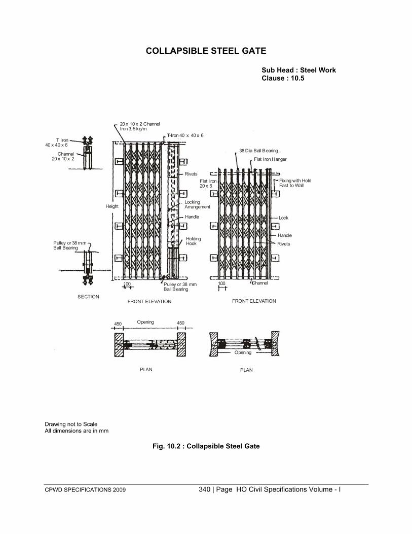
CPWD SPECIFICATIONS 2009 340 | Page HO Civil Specifications Volume - I
COLLAPSIBLE STEEL GATE
Sub Head : Steel Work Clause : 10.5
20 x 10 x 2 ChannelIron 3.5 kg/m
T-Iron 40 x 40 x 6T Iron
40 x 40 x 6
Channel20 x 10 x 2
Height
Pulley or 38 mm Ball Bearing
SECTION FRONT ELEVATION FRONT ELEVATION
100 Pulley or 38 mmBall Bearing
100 Channel
Holding Hook
Handle
LockingArrangement
RivetsFlat I ron20 x 5
38 Dia Ball Bearing
Flat Iron Hanger
Fixing with Hold Fast to Wall
Lock
Handle
Rivets
450 Opening 450
PLAN PLAN
Opening
Drawing not to Scale All dimensions are in mm
Fig. 10.2 : Collapsible Steel Gate

341 | P a g e H O C i v i l S p e c i f i c a t i o n s V o l u m e - I
FAN CLAMPS Sub Head : Steel Work Clause : 10.14
Top of Slab
200
A Distribution Reinforcement
Tie Bar
Main Reinforcement Exposed Loop shall be Painted
16 mm φ 200
R.C.C. Slab
R.C.C. Beam Rib
B Reinforcement Bar
Exposed Loop shall be Painted
160
Top Lid 15 th. 36.5
C 76 73 36.5
Bottom Lid 1.5 Th. ELEVATION
3.3 mm Dia Tapped Hole
5 140
16
75 200
25 Min 16
32 16 17
Ceiling Finish
50
100
Top of Slab 75 200
32
100 Min
Ceiling Finish
50 100
Hole for Conduit Entry
1.5
180 14
12 13
SECTION
CIRCULAR CAST IRON BOX
58.5
PLAN WITHOUT TOP AND BOTTOM LID
Drawing not to Scale All dimensions in millimetres
Fig. 10.9 : Fan Clamps

342 | P a g e H O C i v i l S p e c i f i c a t i o n s V o l u m e - I
11.0: Flooring
343 | P a g e H O C i v i l S p e c i f i c a t i o n s V o l u m e - I
CONTENTS
Clause No. Description Page No.
List of Mandatory Tests 345
List of Bureau of Indian Standards Codes 346 11.1 Brick on Edge Flooring 347 11.2 Cement Concrete Flooring 348 11.3 Cement Concrete Flooring with Metallic Hardner Topping 350 11.4 Cement Plaster in Risers of Steps, Skirting & Dado 351 11.5 Cement Concrete Pavement in Courtyard and Terrace, etc. 352 11.6 Terrazo (Marble Chips) Flooring laid in situ - DELETED 352 11.7 Terrazo (Marble Chips) Skirting in situ - DELETED 352 11.8 Wax Polishing 352 11.9 Crazy Marble Flooring - DELETED 353 11.10 Terrazo Tile Flooring 353 11.11 Terrazo Tiles in Risers of Steps, Skirting & Dado 355 11.12 Chequered Tile Flooring 356 11.13 Chequered Tiles in Stair Treads 357 11.14 Acid or Alkali Resistant Tiles - DELETED 358 11.15 Pressed Ceramic Tiles Flooring 358 11.16 Pressed Ceramic Tile Flooring (Vitrified Tile Flooring) 359 11.17 Fixing of Tile Flooring with Cement based High Polymer 360
Modified Quick Set Adhesive (Water Based) 11.18 Pressed Ceramic Tiles in Skirting & Dado. 360 11.19 Marble Stone Flooring 361 11.20 Marble Stone in Risers of Steps and Skirting 363 11.21 Kota Stone Flooring 364 11.22 Kota Stone in Risers of Steps, Skirting & Dado 364
344 | P a g e H O C i v i l S p e c i f i c a t i o n s V o l u m e - I
11.23 Red or White Fine Dressed Sand Stone Flooring 365 11.24 Red or White Fine Dressed and Rubbed Sand Stone Flooring 366 11.25 Wooden Flooring 366 11.26 Wood Block Flooring 366 Appendix A Abrasion Test for Concrete Hardening Compounds 367 Appendix B Test Requirements and Procedure for Testing Pre-Cast Cement 368
Concrete/Terrazo Tiles Fig. 11.1 Crazy Marble Flooring - DELETED Fig. 11.2 Chequred Terrazo Tiles 369

345 | P a g e H O C i v i l S p e c i f i c a t i o n s V o l u m e - I
LIST OF MANDATORY TESTS
Materia l Clause Test F ie ld/ Test Min.quantity Frequency of
Laboratory Procedure of materia l for testing Test carrying out
the te st 1. 2. 3. 4. 5. 6. 7. Terrazzo 11.10.1 & 1. Transverse Laboratory I S: 1237 5000 Nos. (no One test for every Tiles 11.11.1 strength testing need 10,000 Nos. or part
2. Water be done if thereof for each type absorption total number and size from a
3. Abrasion of tiles of all single manufacturer. Atest types of all (One test to be done
sizes from all even if the number manufacturers of terrazo tiles of any used in a work type and size from a is less than single manufactur- 5000 Nos) ers is less than
5000 Nos. provided the total number of terrazo tiles of all types and sizes from all manufacturers used in a work exceed 5000 Nos.
Pressed 11.4,11.5 1. Dimensions Laboratory I S: 13630 3000 Nos. 3000 Nos. or part ceramic & 11.16 and surface thereof tiles (for quality floor 2. Physical & wall) properties
3. Chemical properties
.

346 | P a g e H O C i v i l S p e c i f i c a t i o n s V o l u m e - I
LIST OF BUREAU OF INDIAN STANDARDS CODES
S.No. IS No. 1. IS 269 2. IS 401 3. IS 451 4. IS 455 5. IS 661 6. IS 702 7. IS 1124 8. IS 1130 9. IS 1141 10. IS 1200-(Part XI ) 11. IS 1237- Edition 2.3 12. IS 1322 13. IS 1443 14. IS 1489 (Part-I) 15. IS 1489-(Part II) 16. IS 1580 17. IS 2114 18. IS 2571 19. IS 3622 20. IS 3670 21. IS 4457 22. IS 5318 23. IS 5766 24. IS 8041 25. IS 8042 26. IS 8043 27. IS 8112 28. IS 12330 29. IS: 13630 (Part-1 to 15) 30. IS 13712 31. IS 15622
Subject
Specification f or 33 gr ade ordinary portland Cement Code of practice for preservation of timber Technical s upply c onditions for w ood s crews Specification for portland slag cement Code of practice f or t hermal insulation of c old s torages Specification for industrial bitumen Method of test for determination of water absortion, apparent specific gravity and porosity of natural building stones Specification f or m arble ( blocks, s labs an d t iles) Code of practice for Seasoning of timber Method of m easurement o f Building and Civil E ngineering work (Part 11) paving, floor finishes, dado and skirting Specification for cement concrete flooring tiles Specification for bitumen felts for water proofing and damp- proofing Code of p ractice for laying and f inishing of cement concrete flooring tiles Specification f or por tland poz zolana c ement (Part-I) flyash based Specification f or P ortland poz zolana c ement ( Part I I) c alcined clay based Specification f or bituminous c ompounds f or water proofing and caulking purpose Code of practice for laying in-situ terrazzo floor finish Code Code of practice for laying in-situ cement concrete flooring Specification for sand stone (Slab & Tiles) Code of practice f or construction of t imber floors Acid and/or alkali Resistant tiles. Code of practice for laying of har d wood parquet and wood block floors Code of practice for laying of burnt clay brick floor Specification for rapid hardening portland c ement Specification for white portland cement Specification for hydrophobic portland cement Specification for 43 grade ordinary portland cement Specification for sulphate resisting portland cement. Methods of Testing of ceramic tiles Specification for ceramic tiles; definition, classification characteristic and marking Specification for pressed ceramic tile

347 | P a g e H O C i v i l S p e c i f i c a t i o n s V o l u m e - I
11.0 FLOORING
11.1 BRICK ON EDGE FLOORING
11.1.1 Bricks Bricks of Specified class designations shall be used. These shall conform to the specifications
described in Subhead 6.0. Broken br icks shall not be us ed in flooring except for c losing the l ine. The bricks shall be laid on edge.
11.1.2 Mortar The mortar used shall be as specified (in case of dry bricks f looring f ine sand shall be f illed in the
joints).
11.1.3 Base Concrete
11.1.3.1 Flooring shall be laid on base concrete where so provided. The base concrete shall be provided with the s lope required for the flooring. F loors in v erandah, courtyard k itchens, ba ths s hall have s lope ranging from 1 : 36 to 1 : 48 d epending upon locations as decided by the Engineer-in-Charge. Floors in water closet portion shall have slope of 1 : 30 or as decided by the Engineer-in-Charge to drain off washing water. Plinth masonry off-set shall be depressed so as to allow the base concrete to rest on it.
11.1.3.2 If the base is of lean cement concrete, the flooring shall commence within 48 hours of the laying of base, failing which, the surface of base shall be roughened with steel wire brushes without disturbing the concrete. Before laying the f looring the base shall be w etted and smeared with a coat of cement slurry at 2 kg of cement spread over an area of one sqm so as to get a good bond between sub-grade and flooring.
11.1.3.3 Where base concrete is not provided, the earth below shall be properly sloped, watered, rammed and consolidated. Before laying the flooring, it shall be moistened.
11.1.4 Soaking of Bricks Bricks required for flooring shall be perfectly soaked in s tacks before use, by profusely spraying
clean water at regular intervals for a period of not less than six hours so as to keep them wet to the satisfaction of the Engineer-in-Charge. (In case the joints are to be filled with sand, the bricks need not be soaked).
11.1.5 Laying
11.1.5.1 The bricks shall be l aid on t he edge, diagonal herring bone bond, or other pattern as specified or directed by the Engineer-in-Charge.
11.1.5.2 Bricks shall be laid on e dge on 12 mm thick mortar of specified ratio bed and each brick shall be properly bedded and set home by gentle tapping with trowel handle or wooden mallet. Its inside face shall be buttered with mortar, before the next brick is laid and pressed against it. 11.1.5.3 On completion of a portion of flooring, the vertical joints shall be fully filled from the top with mortar. During laying, the surface of the flooring shall be frequently checked with a straight edge of length at least 2 m, so as to obtain a true plain surface with the required slope.
11.1.6 Joints Bricks shall be so laid that all joints are full of mortar. The thickness of joints shall not exceed 1.0 cm
for brick work with bricks of any class designation. All face joints shall be raked to a minimum depth of 15 mm by raking tool during the progress of work when the mortar is still green so as to provide proper key for the plaster or pointing to be done. Where plastering or pointing is not required to be done, the joints shall be struck flush and finished at the time of laying. The face of brick work shall be cleaned on the same day on which brick work is done and all mortar droppings removed promptly.
348 | P a g e H O C i v i l S p e c i f i c a t i o n s V o l u m e - I
11.1.7 Curing
Brick work shall be protected from rain by suitable covering when the mortar is green. Brick work in cement mortar, shall be kept constantly moist on al l faces for a m inimum period of seven days. Brick work carried out shall be suitably marked indicating the date on w hich the work is done s o as to keep a watch on the curing period.
11.1.8 Measurements Length and breadth of the flooring shall be m easured correct to a c m and area shall be c alculated in
square metres correct to two places of dec imal. Length and br eadth shall be m easured before laying skirting, dado or wall plaster. No deduction shall be m ade nor extra paid for voids not exceeding 0.20 sqm. Deduction for ends of dissimilar materials or ot her art icles embedded shall not be m ade for areas not exceeding 0.10 sqm.
Brick flooring when laid in diagonal her ring bone bond or other pat tern as specified or di rected by the Engineer-in-Charge shall be measured separately.
11.1.9 Rate The rate shall include the cost of all materials and labour involved in all the operations described
above, including application of cement s lurry on base concrete or RCC slab and c leaning of base. Base concrete shall be paid for separately.
11.1.10 Dry Brick Flooring All provisions of para’s 11.1.1 to 11.1.8 will be applicable except that bricks need not be soaked.
Bricks will be laid on a bed of 12 mm thick mud mortar laid to required slope. The joints shall be as thin as possible and not exceeding 5 mm which will be filled with fine sand. No curing is to be done. 11.1.10.1 Rate: The rate shall include the cost of all materials and labour involved in all the operations described above. 11.2 CEMENT CONCRETE FLOORING
11.2.1 Cement Concrete Cement concrete of specified mix grade shall be used and it shall generally conform to the
specifications described under sub head 4.0 . 11.2.2 Base Concrete
11.2.2.1 Flooring shall be laid on base concrete where so provided. The base concrete shall be provided with the slopes required for the f looring. Flooring in verandah, Courtyard, k itchens & baths shall have slope ranging from 1 : 48 to 1 : 60 depending upon location and as decided by the Engineer-in-Charge. Floors in water c loset portion shall have s lope of 1:30 or as decided by the Engineer-in-Charge to drain off washing water. Further, necessary drop in flooring in bath, WC, kitchen near floor traps ranging from 6 mm to 10 mm will also be provided to avoid spread of water. Necessary margin to accommodate this drop shall be made in base concrete. Plinth masonry off set shall be depressed so as to allow the base concrete to rest on it. 11.2.2.2 The flooring shall be commenced preferably within 48 hours of the laying of base concrete. The surface of the base shall be roughened with steel wire brushes without disturbing the concrete. Immediately before laying the flooring, the base shall be wetted and a coat of cement slurry @ 2 kg of cement spread over an area of one sqm so as to get a good bond between the base and concrete floor.
11.2.2.3 If the cement concrete flooring is to be laid directly on the RCC slab, the top surface of RCC slab shall be cleaned and the laitance shall be removed and a coat of cement slurry @ 2 kg of cement spread over an area of one sqm so as to get a good bond between the base and concrete floor.

349 | P a g e H O C i v i l S p e c i f i c a t i o n s V o l u m e - I
11.2.3 Thickness
The thickness of floor shall be as specified in the description of the item. 11.2.4 Laying
11.2.4.1 Panels : Flooring of specified thickness shall be laid in the pattern including the border as given in the d rawings o r as d irected b y t he E ngineer-in-Charge. The bo rder panel s s hall not e xceed 450 mm in width and the joints in the border shall be in line with panel joints. The panels shall be of uniform size and no dimension of a panel shall exceed 2 m and the area of a panel shall not be more than 2 sqm. The joints of borders at corners shall be mitred for provision of strips.
11.2.4.2 Laying of Flooring with Strips : Normally cement concrete f looring shall be laid in one operation us ing gl ass/aluminium/PVC/brass s trips/stainless s teel s trips o r an y ot her strips as r equired as per drawing or instructions of the Engineer-in-Charge, at the junction of two panels. This method ensures uniformity in colour of all the panels and straightness at the junction of the panels. 2 mm PVC strips s hall be fixed w ith their tops a t proper l evel, gi ving requi red slopes. Cost of pr oviding an d f ixing strips shall be included in the rate.
Concreting : Cement concrete shall be placed in the panels and be levelled w ith the help of s traight edge and t rowel and beat en with thapy or mason’s trowel. The bl ows shall be f airly heavy in the beginning but as consolidation takes place, l ight rapid s trokes shall be given. Beating shall cease as soon as the surface is found covered with a thin layer of cream of mortar. The evenness of the surface shall be tested with straight edge. Surface of f looring be t rue to requ ired s lopes. While laying concrete, care shall be taken to see that the strips are not damaged/disturbed by the labourers. The tops of strips shall be visible clearly after finishing with cement slurry.
Shuttering : The panels shall be bounded by angle iron or f lats. The angle iron/flat shall have the same depth as the concrete flooring. These shall be fixed in position, with their top a t proper level giving required s lopes. The surface of the angle iron or flats, to come in contact with concrete shall be smeared with soap solution or non-sticking oi l (Form oi l or raw l inseed oi l) before concreting. The f looring shall butt against the unplastered masonry wall.
Concreting : The c oncreting shall be done i n t he manner described under 11.2.4.2. The angle i ron/ flats used for shuttering, shall be removed on the next day of the laying of cement concrete. The ends thus exposed shall be repaired, if damaged with cement mortar 1 : 2 (1 cement : 2 coarse sand) and allowed to set fo r minimum p eriod of 24 h ours. T he alternate p anels s hall t hen be c leaned of d ust, mortar, droppings etc. and concrete laid. While laying concrete, care shall be taken to see that the edges of the previously laid panels are not damaged and fresh mortar is not splashed over them. The joints between the panels should come out as fine straight lines.
11.2.5 Finishing 11.2.5.1 The finishing of the surface shall follow immediately after the cessation of beating. The surface shall be left for some time, till moisture disappears from it or surplus water can be mopped up. Use of dry cement or c ement a nd s and mixture stiffening the concrete t o a bsorb excessive moisture shall not be permitted. Excessive trowelling shall be avoided.
11.2.5.2 Fresh cement shall be mixed with water to form a thick slurry and spreaded @ 2 kg of cement over an area of one sqm of flooring while the flooring concrete is still green. The cement slurry shall then be properly processed and finished smooth.

350 | P a g e H O C i v i l S p e c i f i c a t i o n s V o l u m e - I
11.2.5.3 The edges of sunk floors shall be finished and rounded with cement mortar 1:2 (1 cement : 2 coarse sand) and finished with a floating coat of neat cement. 11.2.5.4 The junctions of floor with wall plaster, dado or skirting shall be rounded off where so specified.
11.2.5.5 The men engaged on f inishing operations shall be pro vided with raised wooden platform to sit on so as to prevent damage to new work.
11.2.6 Curing The curing shall be done for a minimum period of ten days. Curing shall not be commenced until the
top layer has hardened. Covering with empty gunnies bag shall be avoided as the colour of the flooring is likely to be bleached due to the remanents of cement dust from the bags.
11.2.7 Precautions Flooring in lavatories and bath room shall be laid only after fixing of water closet and squatting pans
and floor traps. Traps shall be plugged while laying the floors and opened after the floors are cured and cleaned. Any damage done to W.C.’s squatting pans and f loor t raps during the execution of work shall be made good.
During cold weather, concreting shall not be done when the temperature falls below 4°C. The concrete placed shall b e protected aga inst f rost by suitable covering. Concrete dam aged by f rost shall be removed and work redone. During hot weather, precautions shall be taken to see that the temperature of wet concrete does not exceed 38° C. No concreting shall be l aid within half an hour of the closing t ime o f the da y, unless permitted b y t he Engineer-in-Charge. To facilitate rounding of j unction of skirting, dado and f loor, the skirting/dado shall be l aid along with the border or adjacent panels of floor.
11.2.8 Measurement Length and breadth shall be measured before laying skirting, dado or wall plaster. No deduction shall be
made nor extra paid for voids not exceeding 0.20 sqm. Deductions for ends of dissimilar materials or other articles embedded shall not be made for areas not exceeding 0.10 sqm.
The f looring done e ither with strips (in one operation) or without s trips (in al ternate panels) shall be treated as same and measured together. 11.2.9 Rate
The rate shall include the cost of all materials and labour involved in all the operations described above i ncluding appl ication o f c ement s lurry on R CC slab o r on bas e c oncrete i ncluding roughening and cleaning the surface but excluding the cost of s trips which shall be paid separately under relevant i tem. Nosing of steps where provided shall be paid for separately in running metre. Nothing extra shall be paid for laying the floor at different levels in the same room or courtyard and rounding off edges of sunk floors. In case the flooring is laid in alternate panels, nothing extra shall be paid towards the cost of shuttering used for this purpose.
11.3 CEMENT CONCRETE FLOORING WITH METALLIC HARDENER TOPPING 11.3.0 Wherever f loors are required to withstand heavy wear and t ear, use of f loor hardener shall be avoided as far as possible by using richer mixes of concrete, unless the use of a metallic hardner is justified on the basis of cost. Where metallic hardener topping is used, it shall be 12 mm thick.
11.3.1 Metallic Hardening Compound The compound shall be of approved quality consisting of uni formally graded i ron particles, f ree f rom
non-ferrous metal particles, oil, grease sand, soluble alkaline compounds. Where so directed by the Engineer-in-Charge it shall be tested as described in Appendix A.

351 | P a g e H O C i v i l S p e c i f i c a t i o n s V o l u m e - I
11.3.2 Base Concrete
It shall be as specified in 11.2.2.
11.3.3 Under Layer Cement concrete f looring of specified thickness and mix (mentioned in i tem for under layer) shall be
laid as under layer (11.2.1 and 11.2.4). The top surface shall be ro ughened with brushes while the concrete is still green and the forms/strips shall be kept projecting up 12 mm over the concrete surface, to receive the metallic hardening compound topping. 11.3.4 Topping
This shall consist of 12 mm thick layer of mix 1:2 (1 cement : 2 s tone aggregate 6 mm nominal size) by volume or as otherwise specified with which metallic hardening compound is mixed in the ratio of 1 : 4 (1 m etallic concrete hardener : 4 c ement) by weight. Metallic hardener shall be dry m ixed thoroughly with cement on a c lean dry pacca platform. This dry mixture shall be mixed with stone aggregate 6 mm nominal size or as otherwise specified in the ratio of 1 : 2 (1 cement : 2 stone aggregate) and well turned over. Just enough water shall then be added to this dry mix as required for floor concrete.
The mixture so obtained shall be laid in 12 mm thickness, on cement concrete f loor within 2 to 4 hours of its laying. The topping shall be laid true to provide a uniform and even surface. It shall be firmly pressed into the bottom concrete so as to have good bond w ith i t. After the initial set has started, the surface shall be finished smooth and true to slope with steel floats.
The junction of f loor with wall plaster, dado or skirting and f inishing operations shall be dealt with as described in 11.2.5.
The men engaged on finishing operations shall be provided with raised wooden platform to sit on, so as to prevent damage to new work.
11.3.5 The specifications for curing, precautions to be t aken, ‘Measurements’ and ‘ Rates’ shall be a s specified in 11.2.
11.4 CEMENT PLASTER IN RISERS OF STEPS, SKIRTING, DADO
11.4.0 Plaster at the bottom of wall not exceeding 30 cm in height above the floor shall be c lassified as skirting. It shall be flush with wall plaster or projecting out uniformly by 6 mm from the wall plaster, as specified. The work shall be pr eferably carried out s imultaneously w ith the laying of f loor. I t’s corners and junctions with floor shall be finished neatly as specified.
11.4.1 Thickness The thickness of the plaster specified shall be measured exclusive of the thickness of key i.e. grooves or
open joints in brick work. The average thickness shall not be l ess than the specified thickness. The average thickness s hould be r egulated at t he t ime of pl astering b y k eeping s uitable t hickness of t he gaug es. E xtra thickness required in rounding of corners at junctions of wall shall be ignored.
11.4.2 Preparation of Wall Surface The joints shall be raked out to a depth of at least 15 mm in masonry walls. In case of concrete walls,
the surfaces shall be roughened by hacking. The surface shall be cleaned thoroughly, washed with water and kept wet before skirting is commenced.
11.4.3 Application Skirting with specified mortar and to specifed thickness shall be laid immediately after the surface
is prepared. It shall be laid along with the border or adjacent panels of floor. The joints in skirting shall be kept true and straight in continuation of the line of joints in borders or adjacent panels. The skirting shall be finished smooth with top truly horizontal and joints truly vertical except where otherwise indicated.

352 | P a g e H O C i v i l S p e c i f i c a t i o n s V o l u m e - I
11.4.4 Finishing
The finishing of surface shall be done s imultaneously with the borders or the adjacent panels of floor. The cement to be applied in the form of slurry for smooth finishing shall be at the rate of 2 kg of cement per litre of water applied over an area of 1 sqm.
Where skirting is flush with plaster, a groove 10 mm wide and upto 5 mm deep shall be provided in plaster at the junction of skirting with plaster.
11.4.5 Curing Curing shall be commenced on the next day of plastering when the plaster has hardened sufficiently
and shall be continued for a minimum period of 7 days.
11.4.6 Measurement Length and height shall be measured correct to a cm and its area shall be calculated in sqm correct to
two places of decimals for a s pecified the thickness. Length shall be measured as the f inished length of skirting. Height shall be measured from the finished level of floor correct to 5 mm.
11.4.7 Rate Rate shall include the cost of all materials and labour involved in all the operations described above.
11.5 CEMENT CONCRETE PAVEMENT IN COURTYARD AND TERRACE ETC.
11.5.1 Specifications described in 11.2.1, 11.2.2.1, 11.2.3, 11.2.4, 11.2.6 and 11.2.7 shall hold good as far as applicable except that :
(i) The panels shall be of uniform size and no dimension of a panel shall exceed 1.25 m and the area of panel should not exceed 1.25 sqm for the thickness of panels upto 50 mm. (ii) Concreting shall be done in alternate panels only and no glass/asbestos strips shall be provided.
11.5.2 Finishing The finishing of the surface shall follow immediately after the cessation of beating. The surface shall be
left for some-time, till moisture disappears from it or surplus water can be mopped up.
Use of dry cement or cement and sand mix on the surface to s tiffen the concrete or to absorb excessive m oisture s hall not b e p ermitted. E xcessive t rowelling s hall be a voided. W hen t he s urface becomes fairly stiff, it shall be f inished rough with wooden floats or where so specified chequered uniformly by pressing a piece of expanded metal of approved size.
11.5.3 Measurements Same as 11.2.8 except that the volume will be calculated in cum nearest to two decimal places.
11.5.4 Rate The rate shall include the cost of all materials and labour involved in all the operations described
above ex cept t he bas e c oncrete bel ow flooring which s hall be pai d for s eparately. C hequering to pat tern shall be paid for separately unless otherwise specified.
11.6 MARBLE CHIPS FLOORING: DELETED
11.7 MARBLE CHIPS SKIRTING: DELETED
11.8 WAX POLISHING
11.8.1 Application, Polishing and Precautions Wax polish shall be of approved brand and manufacture and in sealed containers. It shall be applied in
uniform layer to the dry surface of the floor/skirting.

353 | P a g e H O C i v i l S p e c i f i c a t i o n s V o l u m e - I
11.8.2 When the layer of the wax is stiffened and surface of f loor is saturated with the polish, polishing shall be resorted with machine fitted with bobs (pad of rags) and shall be done until shades of all chips have appeared and glossy surface is obtained.
11.8.3 The fresh polished floor surface shall be spreaded with dry saw dust to a thickness of about 12 mm uniformly. After the surplus wax has been soaked f rom the floor surface the saw dust shall be removed.
11.8.4 Measurements Length and breadth shall be measured correct to a cm and its area shall be calculated in sqm correct to
two places of decimal.
11.8.5 Rates The rate shall include the cost of all materials and labour involved in all the operations described
above.
11.9 CRAZY MARBLE FLOORING
11.10 TERRAZO TILE FLOORING
11.10.1 Terrazo Tiles Terrazo tiles shall gener ally c onform to I S 123 7-Edition 2. 3. R equirements an d methods o f t esting o f
tiles are described in Appendix B. Unless otherwise specified, the tiles shall be supplied with initial grinding and grouting of wearing layer.
The size of tiles shall be as given in Table 11.2 or as shown in the drawings or as required by the Engineer-in-Charge. Half t iles for use with the full t iles shall be such as to make two half t iles when joined together, match with the dimensions of one full tile.
TABLE 11.2
Length Breadth Thickness not
Nominal Nominal less than 200 mm 200 mm 20 mm 250 mm 250 mm 22 mm 300 mm 300 mm 25 mm
11.10.1.1 Tolerance : Tolerances on length and breadth shall be plus or minus one millimetre, and tolerance on thickness shall be plus 5 mm. The variation of dimensions in any one delivery of tiles shall not exceed 1 mm on length and breadth and 3 mm on thickness. 11.10.1.2 The t iles shall be m anufactured in a factory under pressure process subjected to hydraulic pressure of not less than 140 kg per square centimetre and shall be given the initial grinding with machine and grouting of the wearing layer before delivery to site. The wearing layer shall be free from projections, depressions, cracks, holes, cavities and other blemishes. The edges of wearing layer may be rounded. 11.10.1.3 The proportion of cement to aggregate in the backing of tiles shall be not leaner than 1:3 by weight. Where colouring material is used in the wearing layer, it shall not exceed 10 per cent by weight of cement used in the mix.
11.10.1.4 The finished thickness of the upper layer shall not be l ess than 5 mm for size of marble chips ranging from the smallest upto 6 mm and also, not less than 5 mm for size of marble chips ranging from the smallest upto 12 mm, and not less than 6 mm for size of marble chips varying from the smallest upto 20 mm.
354 | P a g e H O C i v i l S p e c i f i c a t i o n s V o l u m e - I
11.10.2 Laying
11.10.2.1 Base concrete or RCC slab on which the tiles are to be laid shall be cleaned, wetted and mopped. The bedding for the t iles shall be w ith cement mortar o f specified proportion and i n conformity with provisions in relevant para of chapter on ‘Mortar’.
Cement mortar 1:4 (1 Cement : 4 coarse sand) bedding shall be used. A verage thickness of the bedding mortar shall be 20 mm and the thickness at any place shall not be less than 10 mm.
11.10.2.2 Cement mortar bedding shall be spread, tamped and corrected to proper levels and allowed to harden for a day before the tiles are set. If cement mortar is laid in bedding the terrazo tiles, these shall be set immediately after laying the mortar. Over this bedding neat grey cement slurry of honey like consistency shall be spread at the rate of 4.4 kg of cement per square metre over such an area as would accommodate about twenty t iles. Tiles shall be washed c lean and shall be f ixed in this grout one after another, each tile being gent ly tapped with a wooden mallet till i t is properly bedded, and in level with the adjoining tiles. The joints shall be kept as thin as possible not exceeding 1 mm and i n straight lines or to suit the required pat tern. The joints shall be p roperly c leaned before filling with cement grout of matching colour. 11.10.2.3 The surface of the flooring during laying shall be f requently checked with a s traight edge of length at least 2 metre, so as to obtain a true surface with the required slope.
11.10.2.4 Where full tiles or half tiles can not be fixed, tiles shall be cut (sawn) from full tiles to the required size and their edges rubbed smooth to ensure a straight and true joint. 11.10.2.5 Tiles which are fixed in the floor adjoining the wall shall enter not less than 12 m m under t he plaster, skirting o r dado. The junction between wall plaster and t ile work shall be f inished neatly and without waviness.
11.10.2.6 After the tiles have been laid, surplus cement grout that may have come out of the joints shall be cleared off. 11.10.3 Curing, Wax Polishing and Finishing
11.10.3.1 The day after the tiles are l aid all joints shall be c leaned of the grey cement grout with a w ire brush or trowel to a depth of 5 mm and all dust and loose mortar removed and cleaned. Joints shall then be grouted with grey or white cement mixed with or without pigment to match the shape of the topping of the wearing layer of the tiles. The same cement slurry shall be applied to the entire surface of the tiles in a thin coat with a view to protect the surface from abrasive damage and f ill the pin holes that may exist on the surface.
11.10.3.2 The floor shall then be kept wet for a minimum period of 7 days. The surface shall thereafter be grounded evenly with machine fitted w ith coarse grade grit b lock (No. 60). Water shall be u sed profusely during gr inding. After grinding the surface shall be thoroughly washed to remove a ll gr inding mud, cleaned and mopped. It shall then be covered with a thin coat of grey or white cement, mixed with or without pigment to match the colour of the topping of the wearing surface in order to fill any pin hole that appear. The s urface shall be again c ured. The second gr inding s hall then be c arried ou t w ith machine fitted with fine grade grit block (No. 120). 11.10.3.3 The final grinding with machine fitted with the finest grade grit blocks (No. 320) shall be carried out the day after the second grinding described in the preceding para or before handing over the floor, as ordered b y t he Engineer-in-Charge. Wax pol ish s hall be of approv ed brand and m anufacture and i n sealed containers. It shall be applied in uniform layer to the dry surface of the floor. When the layer of the

355 | P a g e H O C i v i l S p e c i f i c a t i o n s V o l u m e - I
wax is stiffened and surface of floor is saturated with the polish, polishing shall be resorted with machine fitted with bobs (pad of rags) and shall be done until shades of all chips have appeared and glossy surface is obtained. The fresh polished floor surface shall be spreaded with dry saw dust to a thickness of about 12 mm uniformly. After the surplus wax has been soaked from the floor surface the saw dust shall be removed.
11.10.3.4 For small areas or w here circumstances so require, hand grinding/polishing with hand grinder may be per mitted i n l ieu o f machine pol ishing a fter laying. F or hand pol ishing t he following carborundum stones, shall be used:
1st grinding — coarse grade stone (No. 60) Second grinding — medium grade (No. 80) Final grinding — fine grade (No. 120)
In all other respects, the process shall be similar as for machine polishing. 11.10.3.5 After the final polish, oxalic acid shall be dusted over the surface at the rate of 33 gm per square metre sprinkled with water and r ubbed hard w ith a ‘namdah’ block (pad of woollen rags). The following day t he f loor s hall be wiped with a m oist r ag an d dr ied with a s oft c loth an d f inished c lean. Wax polishing to be done as given at 11.10.2.3 11.10.3.6 If any tile is disturbed or damaged, it shall be refitted or replaced, properly jointed and polished.
11.10.4 Measurements 11.10.4.1 Terrazo tiles flooring with tiles manufactured from ordinary grey cement without pigment and coloured terrazo t ile f looring shall be m easured separately according to para 11.6.5 Terrazo t ile f looring shall be measured as laid in square metre correct to two p laces of decimal. For length and breadth dimensions c orrect t o a cm before l aying skirting, dado or wall plaster shall be taken. No deduc tion shall be made nor extra paid for voids not exceeding 0.20 sqm. Deductions for ends of dissimilar materials or other articles embedded shall not be m ade for areas not exceeding 0.10 square metre. Nothing extra shall be paid for use of cut tiles nor for laying the floor at different levels in the same room or courtyard. 11.10.4.2 Terrazo tile flooring laid in floor borders and similar band shall be measured under the item of terrazo tile flooring. Nothing extra shall be paid in respect of these and similar bands formed of half size or multiplies of half size standard tiles or other uncut tiles.
11.10.4.3 Treads of stairs and steps paved with t iles without nosing, shall also be m easured under flooring. Moulded nosing shall be paid in running metre except where otherwise stated, returned moulded ends and angl es to mouldings shall be i ncluded in the description. Extra shall, however, be paid for such areas where the width of treads does not exceed 30 cm.
11.10.5 Rate The rate shall include the cost of all materials and labour involved in all the operations described
above. Where cement mortar bedding is used in p lace of l ime mortar the rate will be adjusted accordingly.
11.11 TERRAZO TILES IN RISERS OF STEPS, SKIRTING AND DADO
11.11.1 The terrazo t iles shall be as specified in 11.10.1, as far as appl icable. The minimum finished thickness of tiles shall, however, be 12 mm. The finished thickness of the upper layer shall be not less than 5 mm for size of marble chips from the smallest upto 12 mm and not less than 6 mm for size of chips varying from the smallest upto 20 mm. Where the bigger sized chips are used the tiles shall be not less than 20 mm thick. The requirements of transverse strength tests specified in Appendix B, shall not apply when the tiles used are less than 20 mm thick.
356 | P a g e H O C i v i l S p e c i f i c a t i o n s V o l u m e - I
11.11.2 Preparation of Surface
The specification for this shall be same as specified in 11.4.2.
11.11.3 Laying 12 mm thick plaster of cement mortar 1:3 (1 c ement : 3 c oarse sand) or m ix as specified, shall then
be applied and allowed to harden. The plaster shall then be roughened with wire brushes or by scratching diagonal l ines 2 mm deep at approximately 7.5 cm centres both ways. The back of tiles shall be buttered with a c oat of grey cement slurry and edges with grey or w hite cement slurry with or w ithout pigments to match the shade of tiles, and s et in the bedding mortar. These shall be t amped and corrected to proper pl anes and l ines. The t iles shall be s et in the required pattern and but t jointed. The joints shall be as fine as possible. Top of skirting or dado s hall be t ruly horizontal with projection from finish wall surface not more than tile thickness and joints truly vertical except where otherwise indicated.
The risers of steps, skirting or dado shall rest on the top of the tread or flooring. Where full size tiles cannot be fixed, the tiles shall be cut (sawn) to the required size and their edges rubbed smooth.
11.11.4 Curing, Polishing and Finishing The specifications as in 11.10.3 shall hold good as far as appl icable. Wax Polishing shall be done
only with hand.
11.11.5 Measurements The thickness of the skirting shall be as stated. Le ngth shall be measured along the finished face of
riser, skirting or dado correct to a cm. Height shall be measured from the finished level of tread or floor to the top (the underside of tread in the case of steps). This shall be m easured correct to 5 m m in case of risers and skirting (not exceeding 30 cm in height). In case of heights more than 30 cm, as in the case of dado and on walls, the height shall be measured correct to a cm and s uch work shall be paid for separately. The area shall be calculated in square metre, correct to two places of decimal.
Where the height of risers, skirting or dado does not admit of full size or other finished size tiles and the tiles are to be cut (sawn), nothing extra shall be paid for the same.
11.11.6 Rate The rate shall include the cost of all materials and labour involved in all the operations described
above. Nothing extra shall be payable for use of cut (sawn) tiles to suit the size of risers, skirting, portions of dado etc.
11.12 CHEQUERED TILE FLOORING
11.12.1 Chequered Tiles The tiles shall be of nominal sizes such as 20 × 20 cm, 25 × 25 cm and 30 × 30 cm or of standard
sizes with equal sides. The size of t iles to be used shall be as shown in drawings or a s required by the Engineer-in-Charge. The centre to centre distance of chequers shall not be l ess than 2.5 cm and not more than 5 cm.
The overall thickness of the tiles shall not be less than 30 mm. The grooves in the chequers shall be uniform and straight. The depth of the grooves shall not be less than 3 mm. The chequered t iles shall be cement tiles, or terrazo tiles as specified in the description of the item. The thickness of the upper layer, measured from the top of the chequers shall not be less than 6 mm.
The terrazo tiles shall be given the first grinding with machine before delivery to site.
The t iles shall conform to the specifications for plain cement concrete or terrazo t iles in respect of method of manufacture and the mix of the backing and wearing layers.

357 | P a g e H O C i v i l S p e c i f i c a t i o n s V o l u m e - I
11.12.2 Laying, curing, Polishing and F inishing shall be as specified in 11.10.2 and 11. 10.3 except that wax polishing will not be done and the polishing of the tiles and the chequer grooves, after laying, may be done by hand. Special care shall be taken to pol ish the grooves in such a manner as to get a uni form section and t hat their f inish shall match with the finish of flat portion of the tiles. Cement concrete tiles normally d o n ot re quire po lishing but w here polishing is r equired t he s ame s hall be done as des cribed above.
11.12.3 Measurement and Rate: Shall be as specified in 11.10.4 and 11.10.5.
11.13 CHEQUERED TILES IN STAIR TREADS (FIG. 11.2)
11.13.1 Chequered Tiles The specifications for tiles shall be as specified in 11.12.1 except in the following respects :
(1) The length of the tiles including nosing shall be as specified.
(2) The nosing edge of the tile shall be rounded.
(3) The minimum thickness of the tile shall be 30 mm.
(4) The front portion of the tile for a minimum length of 75 mm from and including the nosing shall have grooves running parallel to the nosing and at centres not exceeding 25 mm. Beyond that the tiles shall have the normal chequer pattern.
(5) The nosing shall also have the same wearing layer as the top.
11.13.2 Preparation of Surface and Laying 11.13.2.1 RCC or brick work in treads on which the tiles are to be laid shall be cleaned wetted and mopped. The bedding for t iles shall be with cement mortar 1:4 (1 cement : 4 coarse sand) or of specified mix. The m inimum thickness of bedding mortar at an y pl ace shall be 10 m m. Bedding mortar shall be spread, tamped and corrected to proper levels. A fter laying bedding mortar, neat grey cement slurry of honey like consistency shall be spread over the mortar at the rate of 4.4 kg of cement per square metre over each t read. T iles shall be washed cleaned and shall be f ixed in this grout butting one at another. Each tile being gently tapped with a wooden mallet till it is properly bedded, and is in level and line with the adjoining t iles. T he j oints s hall be k ept as t hin a s pos sible an d i n s traight lines. The surface s hall b e checked with a straight edge during laying to obtain a true surface.
11.13.2.2 The square end of the tile shall, as far as possible butt against the riser face of the concrete or brick tread and in any case shall be embedded under the side wall plaster, skirting or dado and under the riser tile or other finish to a depth of not less than 10 mm.
11.13.2.3 Where full size tiles cannot be f ixed, these shall be c ut (sawn) to the required size (along the groove of the chequers where the cut edge is exposed) and used. The cut in the case of embedded edges will be neat and true while the cut in the case of exposed edges shall in addition be rubbed smooth to ensure a straight and true joints.
11.13.2.4 After the tiles have been laid surplus cement grout shall be cleaned off.
11.13.3 Curing, Polishing and Finishing The specifications shall be as described in 11.12.2 except that pol ishing of the t reads nos ing and
chequered grooves, af ter laying, may be don e by hand in the same manner as specified under terrazo tile f looring. Special care shall be taken to polish the nosing and the grooves in such a manner as to get a uniform, section for the grooves and the nosing and their finish shall match with the finish of the flat portion of the tiles.

358 | P a g e H O C i v i l S p e c i f i c a t i o n s V o l u m e - I
11.13.4 Measurements
Chequred tiles on stair treads shall be measured in square metre correct to two places of decimal. Length shall be measured correct to a cm before laying skirting, dado or wall plaster. Width shall be measured correct to a c m from the outer edge of the nosing, as laid, before providing the riser. In the case of the edge tiles of the landing and wide steps, width shall be measured upto the near edge of the chequered stair t read t iles. Deductions for ends of dissimilar materials or o ther art icles embedded shall not be made for areas not exceeding 0.10 square metre.
11.13.5 Rate The rate shall include the cost of all materials and labour involved in all the operations described
above. Nothing extra shall be payable for cutting the tiles to suit the size of treads and also for nosing.
11.14 ACID OR ALKALI RESISTANT TILES : DELETED 11.15 CERAMIC TILE FLOORING
11.15.1 Ceramic Tiles The tiles shall be of approved make and shall generally conform to IS 15622. They shall be flat, and
true to s hape and f ree f rom b listers c razing, chips, welts, c rawling or ot her i mperfections det racting f rom their app earance. The tiles shall be t ested as pe r IS 13630. Classification an d C haracteristics of pr essed ceramic tiles shall be as per IS 13712.
The t iles shall be square or rectangular of nominal size. Table 1,3,5, and 7 of IS 15622 give the modular p referred s izes and table 2,4,6 and 8 give the most common non modular s izes. Thickness shall be specified by the manufacturer. It includes the profiles on the visible face and on the rear side. Manufacturer/supplier and party s hall choose the work size o f t iles i n order to al low a nominal joint w idth upto 2mm for unrectified floor tiles and upto 1mm for rectified floor tiles. The joint in case of spacer lug tile shall be as per s pacer. The tiles shall conform to table10 of IS 15622 with water absorption 3 t o 6% (Group BII).
The top surface of the tiles shall be gl azed. Glaze shall be e ither glossy or matt as specified. The underside of the tiles shall not have glaze on m ore than 5% of the area i n order that the tile may adhere properly to the base. The edges of the t iles shall be pr eferably free from glaze. However, any glaze if unavoidable, shall be permissible on only upto 50 per cent of the surface area of the edges.
11.15.2 Coloured Tiles Only the glaze shall be coloured as specified. The sizes and specifications shall be the same as for
the white glazed tiles. 11.15.3 Decorative Tiles
The type and size of the decorative tiles shall be as follows : (i) Decorated white back ground tiles
The size of these tiles shall be as per IS 15622.
(ii) Decorated a nd h aving c oloured back-ground The sizes of the tiles shall be as per IS 15622.
11.15.4 Preparation of Surface and Laying 11.15.4.1 Base concrete or t he RCC slab on which the tiles are t o be l aid shall be c leaned, wetted and mopped. The bedding for the ti le shall be with cement mortar 1:4 (1 cement : 4 coarse sand) or as specified. The average thickness of the bedding shall be 20 mm or as specified while the thickness under any portion of the tiles shall not be less than 10 mm.

359 | P a g e H O C i v i l S p e c i f i c a t i o n s V o l u m e - I
11.15.4.2 Mortar shall be s pread, tamped and corrected to proper levels and al lowed to harden sufficiently to offer a f airly rigid cushion for the tiles to be s et and t o enable the mason to place wooden plank across and squat on it. 11.15.4.3 Over this mortar bedding neat grey cement slurry of honey like consistency shall be spread at the rate of 3.3 kg of cement per square metre over an area upto one square metre. T iles shall be soaked in water washed clean and shall be fixed in this grout one after another, each tile gently being tapped with a wooden mallet till it is properly bedded and in level with the adjoining tiles. The joints shall be kept as thin as possible and in straight lines or to suit the required pattern.
11.15.4.4 The surface of the flooring during laying shall be frequently checked with a straight edge about 2 m long, so as to obtain a t rue surface with the required slope. In bath, toilet W.C. kitchen and balcony/verandah flooring, suitable t ile drop or as shown in drawing w ill be g iven in addi tion to required slope to avoid spread of water. Further tile drop will also be provided near floor trap. 11.15.4.5 Where full size tiles cannot be fixed these shall be cut (sawn) to the required size, and their edge rubbed smooth to ensure straight and true joints.
Tiles which are f ixed in the floor adjoining the wall shall enter not less than 10 mm under the plaster, skirting or dado.
11.15.4.6 After tiles have been laid surplus cement slurry shall be cleaned off.
11.15.5 Pointing and Finishing The joints shall be c leaned off the grey cement slurry with wire/coir brush or trowel to a depth of 2
mm to 3 mm and all dust and loose mortar removed. Joints shall then be flush pointed with white cement added with pigment i f required to match the colour of t iles. Where spacer lug t iles are provided, the half the depth of joint shall be f illed with polysulphide or as specified on t op with under f illing with cement grout w ithout the lugs remaining exposed. The f loor shall then be k ept wet for 7 day s. After curing, the surface shall be w ashed and f inished clean. The f inished f loor shall not sound hol low when tapped w ith a wooden mallet.
11.15.6 Measurements Length and breadth shall be measured correct to a cm before laying skirting, dado or wall plaster and the
area ca lculated i n s quare m etre correct to t wo places of d ecimal. W here co ves ar e us ed a t th e junctions, the length and breadth shall be measured between the lower edges of the coves.
No deduction shall be made nor ex tra paid for voids not exceeding 0.20 square metre. Deductions for ends of dissimilar materials or other articles embedded shall not be made for areas not exceeding 0.10 square metre.
1.15.7 Rate The rate for f looring shall include the cost of al l materials and l abour involved in al l the operations
described above, Nothing extra shall be paid for the use of cut (sawn) tiles in the work. Rate shall include colour tiles.
11.16 VITRIFIED TILE FLOORING
11.16.1 Operations as de scribed i n 1 1.15.1 t o 11 .15.6 s hall be f ollowed ex cept t he t iles s hall c onform t o Table 12 of IS 15622 ( Tiles w ith water absorption E ≤ 0.08 per cent Group BIa) and t he joint thickness in flooring shall not be more than 1mm.
11.16.2 Rate The rate for flooring shall include the cost of all materials and labour involved in all the operations
described above. Nothing extra shall be paid for the use of cut (sawn) tiles in the work.

360 | P a g e H O C i v i l S p e c i f i c a t i o n s V o l u m e - I
11.17 FIXING OF TILE FLOORING WITH CEMENT BASED HIGH POLYMER MODIFIED QUICK SET ADHESIVE (WATER BASED)
11.17.1 When tile flooring is to be laid over the existing flooring without dismantling old flooring it can be laid with a dhesive. T he ol d f looring s hall be t horoughly cleaned an d c hecked f or undu lations, if an y s hall be rectified with cement mortar 1:3 (1 cement: 3 coarse sand). Old cement concrete surface shall be hacked and cleaned off to have proper bond with the old surface.
11.17.2 High pol ymer m odified qui ck s et t ile adhes ive ( conforming t o I S 15477) shall be t horoughly mixed with water and a paste of zero slump s hall be prepared s o t hat i t can b e used with i n 1.5 t o 2 hours. It shall be spread ove r an area not more than one sqm a t one time. Average thi ckness of adhesive s hall be 3 m m The a dhesive s o s preaded shall be c ombed us ing s uitable t rowel. T iles s hall be pressed f irmly i n to the position with slight twisting action checking i t s imultaneously t o ens ure go od contact gently being tapped with wooden mallet till it is properly backed with adjoining tiles. The tiles shall be fixed within 20 minutes of application of adhesive. The surplus adhesive from the joints, surface of the tiles shall be immediately cleaned. 11.17.3 The surface of the flooring shall be frequently checked during laying with straight edge of above 2m long so as to attain a true surface with required slope. 11.17.4 Where spacer lugs tiles are provided these shall be filled with grout with lugs remaining exposed.
11.17.5 Where f ull s ize tile can not be f ixed these shall be cut (sawn) to the required size and edges rubbed smooth to ensure straight and true joints. Tiles which are fixed in floor adjoining to wall shall enter not less than 10 mm under plaster, skirting or dado.
11.17.6 Finishing: para 11.15.5 shall apply.
11.17.7 Measurements: para 11.15.6 shall apply.
11.17.8 Rate Provisions of para 11.15.7 and 11.16.2 shall apply.
11.18 CERAMIC/VITRIFIED TILES IN SKIRTING AND DADO
11.18.1 The tiles s hall be o f approved make and s hall generally c onform to IS 15622. The t iles shall be pressed ceramic covered by a glaze thoroughly matured and fitted to the body. The tiles shall be sound, true to shape, flat and free from flaws and other manufacturing defects affecting their utility.
The top surface of the tiles shall be glazed. The underside of the tiles shall not have glaze on more than 5% of the area in order that the tile may adhere properly to the base. The edges of the tiles shall be free from glaze, however, any glaze if unavoidable shall be permissible on only upto 50 per cent of the surface area of edges.
The glaze shall be free from welts, chips, craze, specks, crawlings or other imperfections detracting from the a ppearance when viewed f rom a di stance of one m etre. T he gl aze s hall be e ither glossy or m att as specified. T he glaze shall be white in c olour ex cept i n t he c ase of c oloured tiles when c olours s hall b e specified by the Engineer-in-Charge. There may be more than one colour on a tile. 11.18.1 (a) Dimensions and Tolerances
Glazed pressed cramic tiles shall be made square or rectangular in sizes Table 1, 3, 5 & 7 of IS 15622 give the modular sizes and table 2, 4, 6 & 8 of IS 15622 gives the sizes of non modular tiles. The tiles shall conform to IS 15622 for dimensional tolerance, physical and chemical properties.
Half t iles f or use as full t iles shall have dimensions which shall be such as to make the hal f t iles when jointed together (with 1 m m joint) m atch with dimensions of f ull t iles. T iles m ay be m anufactured in s izes other than those specified. above.
The thickness of the tiles shall be 5 mm or 6 mm or as specified.

361 | P a g e H O C i v i l S p e c i f i c a t i o n s V o l u m e - I
The dimensions of f ittings associated with the g lazed til es namely cover base, r ound edge ti le, angles corner cups, ridge and legs, cronices and capping beads shall be of the shape and dimensions as required and the thickness of fittings shall be the same as the thickness of tiles given above.
11.18.2 Preparation of Surfaces The joints shall be raked out to a depth of at least 15 mm in masonry walls. In case of concrete walls, the surface shall be hacked and roughened with wire brushes. The surface
shall be cleaned thoroughly, washed with water and kept wet before skirting is commenced.
11.18.3 Laying 12 mm thick plaster of cement mortar 1:3 (1 cement : 3 c oarse sand) mix of as specified shall be
applied and allowed to harden. The plaster shall be roughened with wire brushes or by scratching diagonal at closed intervals.
The tiles should be soaked in water, washed c lean, and a coat of cement slurry applied liberally at the back of tiles and set in the bedding mortar. The tiles shall be tamped and corrected to proper plane and lines. The t iles shall be s et in the required pattern and j ointed. The joints shall be as fine as possible. Top of skirting or dado shall be truly horizontal and joints t ruly vertical except where otherwise indicated. Odd size/cut size of ti le shall be adjusted at bottom to take care of slope of the flooring. Skirting and dado shall rest on t he top of the flooring. Where full size tiles cannot be f ixed these shall be cut (sawn) to the required s ize and t heir edges rubbed smooth. Skirting /dado shall not project from the finished “surface of wall” by more than the tile thickness, undulations if any shall be adjusted in wall.
11.18.4 Curing and Finishing The joints shall be c leaned off the grey cement grout with wire/coir brush or trowel to a depth of 2
mm to 3 mm and all dust and loose mortar removed. Joints shall then be flush pointed with white cement added with pigments if required to match the colour of tiles. The work shall then be kept wet for 7 days.
After cur ing, the surface shall be washed and f inished clean. The f inished work shall not sound hollow when tapped with a wooden mallet.
11.18.5 Measurements Length shall be measured correct to a cm. Height shall be measured correct to a cm in the case of
dado and 5 m m in the case of riser and skirting. The area shall be calculated in square metre, correct to two places of dec imal. Length and hei ght shall be measured along the finished face of the skirting or dado including curves where specials such as coves, i nternal and external angles and beads are used. Where cornices are used the area of dado shall be measured excluding the cornices. Nothing extra will be paid for cutting (sawn) the tiles to sizes. 11.18.6 Rates
The rate shall include the cost of all material and labour involved in all the operations described above. The rat e s hall not i nclude c ost of c ornices w hich shall b e m easured and pai d f or i n ru nning meters separately. 11.19 MARBLE STONE FLOORING
11.19.1 Marble Stone It shall be as specified in sub head 8.0.
11.19.2 Dressing of Slabs Every stone shall be c ut to the required size and s hape, f ine chisel dressed on al l sides to the full
depth so that a straight edge laid along the side of the stone shall be fully in contact with it. The top surface shall a lso be f ine chisel dressed to remove a ll waviness. In case machine cut slabs are used, fine chiesel dressing of machine cut surface need not be done prov ided a s traight edge l aid any where along the machine cut surfaces is in contact with every point on i t. The sides and top surface of slabs shall be machine rubbed or table rubbed w ith coarse sand before paving. A ll angles and edges of the marble slabs shall be true, square and free from chippings and the surface shall be true and plane.
362 | P a g e H O C i v i l S p e c i f i c a t i o n s V o l u m e - I
The thickness of the slabs shall be 18, 30 or 40 mm as specified in the description of the i tem. Tolerance of + 3% shall be allowed for the thickness. In respect of length and breadth of slabs a tolerance of + 2% shall be allowed.
11.19.3 Laying 11.19.3.1 Base concrete or the RCC slab on which the slabs are to be laid shall be c leaned, wetted and mopped. The bedding for the slabs shall be with cement mortar 1:4 (1 cement : 4 c oarse sand) or as given in the description of the item. 11.19.3.2 The average thickness of the bedding mortar under the slab shall be 20 mm and the thickness at any place under the slab shall be not less than 12 mm.
11.19.3.3 The slabs shall be laid in the following manner:
Mortar of the specified mix shall be spread under the area of each slab, roughly to t he average thickness specified in the item. The s lab shall be washed clean before laying. It shall be laid on top, pressed, tapped with wooden mallet and brought to level with the adjoining s labs. I t shall be l ifted and laid aside. The top surface of the mortar shall then be c orrected by adding fresh mortar at hollows. The mortar is al lowed to harden a bi t and cement s lurry of honey like consistency shall be spread over the same at the rate of 4.4 kg of cement per sqm. The edges of the slab already paved shall be but tered with grey or white cement with or without admixture of pigment to match the shade of the marble slabs as given in the description of the item.
The slab to be paved shall then be lowered gently back in position and tapped with wooden mallet till it is properly bedded in level with and close to the adjoining slabs with as fine a joint as possible. Subsequent s labs shall be laid in the same manner. After each s lab has been laid, surplus cement on the surface of the slabs shall be cleaned off. The flooring shall be cured for a minimum period of seven days. The surface of the flooring as laid shall be true to levels, and, slopes as instructed by the Engineer-in-Charge. Joint thickness shall not be more than 1 mm.
Due care shall be taken to match the g rains o f slabs which shall be s elected judiciously having uniform pattern of Veins/streaks or as directed by the Engineer-in-Charge. 11.19.3.4 The slabs shall be matched as shown in drawings or as instructed by the Engineer-in-Charge.
11.19.3.5 Slabs which are fixed in the floor adjoining the wall shall enter not less than 12 mm under the plaster skirting or dado. The junction between wall plaster and f loor shall be finished neatly and w ithout waviness.
11.19.3.6 Marble slabs flooring shall also be laid in combination with other stones and/or in simple regular pattern/design as described in item of work and/or drawing.
11.19.4 Polishing and Finishing Slight unevenness at the meeting edges of slabs shall then be removed by f ine chiselling and
finished in the same manner as specified in 11.10.3 except that high g loss mirror f inish po lish shall be done. Cement slurry with or without pigments shall not be applied on the surface before each polishing.
11.19.5 Measurements Marble stone f looring with di fferent k ind of m arble s hall be m easured s eparately and in s quare m etre
correct t o two p laces of decimal. Length and breadth shall be measured correct t o a cm before laying skirting, dado or wall plaster. No deduction shall be m ade nor extra paid for voids not exceeding 0.20 square metre. Deductions for ends of dissimilar materials or other articles embedded shall not be made

363 | P a g e H O C i v i l S p e c i f i c a t i o n s V o l u m e - I
for areas not exceeding 0.10 square metre. Nothing extra shall be pai d for laying the f loor at different levels in the same room. Steps and t reads of stairs paved with marble stone slabs shall also be measured under the i tem of Marble Stone f looring. Extra shall, however, be paid for such areas where the width of treads does not exceed 30 cm. Nosing for treads shall be measured in running metre and paid for extra. The width of treads shall be measured from the outer edge of the nosing, as laid, before providing the riser. 11.19.6 Rate
The rate shall include the cost of all materials and labour involved in all the operations described above. However, extra shall be paid for making special type of pattern/design/flowers as per drawings. No deductions shall be made in rate even if flooring is done without any pattern/design. 11.20 MARBLE STONE IN RISERS OF STEPS AND SKIRTING
11.20.1 Marble Stone Slabs and Dressing of Slabs shall be as specified in 11.19.1 and 11.19.2 except that the thickness of slabs shall be 18 mm. A tolerance of + 3% mm shall be allowed, unless otherwise specified in the description of the item.
11.20.2 Preparation of Surface It shall be a s specified in 11.18.2 where necessary, the wall surface shall be c ut uni formly to the
requisite depth so that the skirting face shall have the projection from the finished face of wall as shown in drawings or as required by the Engineer-in-Charge. In no case the skirting should project by more than thickness of stone.
11.20.3 Laying The risers of steps and skirting shall be in grey or white cement admixed with or without pigment to
match the shade of the stone, as specified in the description of the item, with the line of the slab at such a distance from the wall that the average width of the gap shall be 12 mm and at no place the width shall be less than 10 mm, if necessary, the slabs shall be held in position by temporary M.S. hooks fixed into the wall at suitable intervals. The skirting or r iser face shall be checked for plane and plumb and corrected. The joints shall thus be left to harden then the rear of the skirting or riser slab shall be packed with cement mortar 1:3 (1 cement : 3 c oarse sand) or other mix as specified in the description of the item. The fixing hooks shall be removed after the mortar filling the gap has acquired sufficient strength.
The joints shall be as f ine as possible but not more than 1 m m. The top l ine of skirting and risers shall be truly horizontal and joints truly vertical, except where otherwise indicated.
The risers and skirting slab shall be matched as shown in drawings or as instructed by the Engineerin-Charge. 11.20.4 Curing, Polishing and Finishing
It shall be a s specified in 11.19.4 as f ar as a pplicable, except that cement slurry with or without pigment shall not be applied on the surface and polishing shall be done only with hand. The face and top of skirting shall be polished.
11.20.5 Measurements Length shall be m easured along the finished face of riser or s kirting, correct to a c m. Height shall be
measured from the finished level of tread or floor, to the top (the underside of tread, in the case of steps) correct to 0.5 cm. The areas shall be calculated in square metre correct to two places of decimal.
Dado and l ining of pillars etc. shall be measured as ‘Marble work in wall l ining. I f the thickness is upto 25 mm or as “Marble Work” in Jambs, walls, columns and other plain work’ if the thickness is more.
364 | P a g e H O C i v i l S p e c i f i c a t i o n s V o l u m e - I
11.20.6 Rate The rate shall include the cost of all materials and labour involved in all the operations described
above. 11.21 KOTA STONE FLOORING
11.21.1 Kota Stone Slabs The s labs shall be of selected qual ity, hard, sound, dense and hom ogeneous in texture f ree from
cracks, dec ay, weathering and flaws. They s hall be hand or machine cut t o t he requisite t hickness. They shall be of the colour indicated in the drawings or as instructed by the Engineer-in-Charge.
The s labs shall have the top (exposed) face pol ished before being brought to s ite, unless otherwise specified. The slabs shall conform to the size required. Before starting the work the contractor shall get the samples of slabs approved by the Engineer-in-Charge.
11.21.2 Dressing Every s lab shall be cut to the required s ize and shape and fine chisel dressed on the s ides to the full
depth so that a straight edge laid along the side of the stone shall be in full contact with it. The sides (edges) shall be t able rubbed with coarse sand or machine rubbed before paving. All angles and edg es of the slabs shall be true, square and free from chippings and the surface shall be true and plane.
The t hickness of t he slab af ter i t i s dr essed s hall b e 20, 2 5MM o r as specified i n t he description of the item. Tolerance of ±2 mm shall be allowed for the thickness. In respect of length and breadth of slabs Tolerance of ± 5 mm for hand cut slabs and ± 2 mm for machine cut slabs shall be allowed.
11.21.3 Preparation of Surface and Laying The specification shall be as described in 11.19.3 except that the edges of the slabs to be jointed
shall be buttered with grey cement, with admixture of p igment to match the shade of the slab. The thickness of the joints should be minimum as possible. In any location, it shall not exceed 1 mm.
11.21.4 Polishing and Finishing The specifications shall be as described in 11.10.3 except that (a) f irst polishing with coarse grade
carborundum stone shall not be done, (b) cement slurry with or without pigment shall not be applied on the surface before polishing.
11.21.5 Measurements and Rates These shall be as described in paras 11.19.5 and 11.19.6.
11.22 KOTA STONE IN RISERS OF STEPS, SKIRTING AND DADO 11.22.1 Kota Stone Slabs and Dressing shall be as specified in 11.21.1 and 11.21.2 except that the thickness of the slabs shall be 25 m m or as specified in the description of the item. The slabs may be o f uniform size if required.
11.22.2 Preparation of surface shall be as specified in 11.20.3. 11.22.3 Laying shall be as specified in 11.20.3 except that the joints of the slabs shall be set in grey cement mixed with pigment to match the shade of the slabs.
11.22.4 Curing, Polishing and Finishing shall be as specified in 11.10.3 except that first polishing with coarse grade carborundum stone shall not be done.
11.22.5 Measurements Length shall be m easured along the f inished face of riser, skirting or dado correct to a cm. Height
shall be measured from the finished level of tread of floor to the top (the underside of tread in the case of
365 | P a g e H O C i v i l S p e c i f i c a t i o n s V o l u m e - I
steps). This shall be measured correct to a mm in the case of risers of steps and skirting and correct to a cm in the case of dado. The area shall be calculated in square metre correct to two places of decimal.
Lining of pillars etc. shall also be measured under this item.
11.22.6 Rate The rate shall include the cost of all materials and labour involved in all the operations described
above.
11.23 RED OR WHITE FINE DRESSED SAND STONE FLOORING
11.23.1 Stone Slabs The slabs shall be red or white as specified in the description of the item. The stone slabs shall be
hard, sound, durable and tough, f ree f rom cracks, decay and weathering. In case of red sand stone, white patches or streaks shall not be al lowed. However, scattered spots upto 10 m m diameter will be permitted. Before s tarting the work the contractor shall get samples of s labs approved by the Engineer- in-Charge.
The s labs shall be hand o r machine cut to the requisite t hickness along planes parallel to t he natural bed of stone and should be of uniform size if required.
11.23.2 Dressing of Slabs Every slab shall be cut to the required size and shape and chisel dressed on all sides to a minimum
depth of 20 mm. The top and the joints shall be fine tooled so that straight edge laid along the face is fully in contact with it. In case machine cut stones are used, chisel dressing and fine tooling of machine cut surface need not be don e pr ovided a s traight edg e l aid an ywhere al ong the machine cut s urface i s i n contact with every point on it.
The thickness of the slabs after dressing shall be 40 mm or as specified in the description of i tem with a permissible tolerance of ± 2 mm.
11.23.3 Laying
11.23.3.1 Base concrete on which the slabs are to be laid shall be c leaned, wetted and mopped. The bedding for the slabs shall be w ith cement mortar 1:5 (1 cement : 5 c oarse sand) or as given in the description of the item.
11.23.3.2 The average thickness of the bedding mortar under the slabs shall be 20 mm and the thickness at any place under the slabs shall not be less than 12 mm.
11.23.3.3 The slab shall be laid in the following manner:
Mortar o f specified m ix shall be spreaded under each slab. The slab shall be washed c lean before laying. It shall then be laid on top, pressed and larried, so that a ll hollows underneath get filled and surplus mortar works up through the joints. The top shall be tapped with a wooden mallet and br ought to level and close to the adjoining slabs, with thickness of joint not exceeding 5 mm. Subsequent s labs shall be laid in the same manner. After laying each slab surplus mortar on t he surface of slabs shall be cleaned off and joints finished flush.
11.23.3.4 In case pointing with other mortar mix is specified, the joint shall be left raked out uniformly and to a depth of not less than 12 mm when the mortar is still green. The pointing shall be cured for a minimum period of 7 day s. The surface of the flooring as laid shall be true to levels and slopes as instructed by the Engineer-in-Charge.
11.23.3.5 Slabs which are fixed in the floor adjoining the wall shall enter not less than 12 mm under the plaster, skirting or dado. The junction between wall plaster skirting and f loor shall be f inished neatly and without waviness.

366 | P a g e H O C i v i l S p e c i f i c a t i o n s V o l u m e - I
11.23.3.6 The finished floor shall not sound hollow when tapped with wooden mallet.
11.23.4 Finishing In case of chisel dressed stone flooring slight unevenness, if any existing between the edges of slabs at
joints shall then be removed by chiselling in a slant.
11.23.5 Measurements These shall be as specified in para 11.19.5.
11.23.6 Rate The rate shall include the cost of all materials and labour involved in all the operations described
above. Where pointing i s to be done, this w ill be pai d ex tra unless specifically i ncluded in t he description of the item.
11.24 RED OR WHITE FINE DRESSED AND RUBBED SAND STONE FLOORING
11.24.1 Stone Slabs shall be as specified in 11.23.1.
11.24.2 Dressing The specifications for dressing the top surface and the sides shall be a s described in 11.23.2. In
addition the dre ssed t op and sides shall b e table r ubbed with c oarse grade carborundum s tone before paving, to obtain a perfectly true and smooth surface free from chisel marks.
The thickness of the slabs after dressing shall be as specified with a permissible tolerance of ± 2 mm.
11.24.3 Laying The slabs shall be laid with 3 mm thick or 5 mm thick joints as specified in the description of the item.
Where the joints are to be l imited to 3 mm thickness, the slabs shall be laid as specified in 11.19.3
except that the bedding mortar shall be as specified in 11.23.3 and sides of the slabs to be jointed shall be buttered with cement mortar 1:2 (1 cement : 2 stone dust) admixed with pigment to match the shade of the slab.
Where the slabs are to be laid with 5 m m thick joints, the specifications for laying shall be as described in 11.23.3. 11.24.4 Finishing shall be as specified in 11.23.4 except that chisel marks and unevenness shall be removed by rubbing with coarse grade carborundum stone.
11.24.5 Measurement and Rate shall be as specified in 11.23.5 and 11.23.6.
11.25 WOODEN FLOORING : DELETED
11.26 WOOD BLOCK FLOORING : DELETED.

367 | P a g e H O C i v i l S p e c i f i c a t i o n s V o l u m e - I
APPENDIX A
ABRASION TEST FOR CONCRETE HARDENING COMPOUNDS (Clause 11.3.1)
A-1 Preparation of Sample 25 mm cylinder shall be prepared in ratio 1:2 mix (1 cement: 2 grades stone aggregate 6 mm
nominal s ize by weight) one each with and without the admixture of concrete hardening compound. The concrete hardening compound shall be us ed in the proportion by weight of cement as recommended by the f irm. The cylinder shall be placed inside a damp box for 24 hours and then cured in water for 27 days. After that, they shall be s ubject to abrasion test on ‘ Dorry Type Avery Abrasion Testing Machine, using Emery powder No 80 as the abrasing medium under the condition given in para A-2 below:
A-2 Conditions of Test (a) Area of rubbing surface shall be same in both the cylinders. (b) Age of cylinder 28 days
(c) Duration of Test 60 minutes
(d) Total distance traverse During rubbing About 2.4 km
(e) Pressure on rubbing 0.04 kg/cm2
surface
A-3 Results of Tests The following observations shall be made in both the cases.
(a) Composition of the Test specimen
(b) Mean thickness rubbed away
(c) Percentage loss in weight
A-4 Remarks Percentage l oss i n weight in t he case o f c ylinders w ith c oncrete har dening compound, s hould not be
more than 40% of the percentage loss in the case of cylinder without concrete hardening compound.

368 | P a g e H O C i v i l S p e c i f i c a t i o n s V o l u m e - I
APPENDIX B
TEST REQUIREMENTS AND PROCEDURE FOR TESTING “PRE-CAST CEMENT CONCRETE/ TERRAZO TILES”
(Clause 11.10.1 & 11.11.1) B-1 Sampling
The tiles required o f c arrying out t est des cribed below s hall be taken b y ‘ random s ampling’. Each t ile sample shall be marked to identify the consignement from which it was selected.
Minimum quantity of tiles for carrying out the test and frequency of test shall be as specified in the list of Mandatory Test. The number of tiles selected for each mandatory test shall be as follows”
(a) For conformity to requirements on shape and dimensions, wearing layer, and general quality - 12 tiles
(b) For wet transverse strength test - 6 tiles (c) For resistance to wear test - 6 tiles (d) For water absorption test - 6 tiles
Note: (1) The tests on the tiles shall not be carried out earlier than 28 days from the date of manufacture.
(2) The tiles selected for (a) may as well after verification of requirements, be used for (b).
B-2 Flatness of the Tiles Surface The tiles when tested according to procedure laid down in IS 1237 edition 2.3, the amount of
concavity and convexity shall not exceed 1 mm.
B-3 Perpendicularity When tested in accordance w ith the p rocedure laid down in IS 1237 edition 2.3, the longest gap
between the arm of the square and edge of the tile shall not exceed 2 per cent of the length of edge.
B-4 Straightness When tested as per IS 1237 edition 2.3, the gap between the thread and the plane of tile shall not
exceed 1 percent of the length of edge.
B-5 Water Absorption When tested the average water absorption shall not exceed 10 per cent.
B-6 Wet Transverse Strength Test Six fu ll s ize tiles shall be tested for the determination of wet t ransverse strength. When tested
according to the procedure laid down in IS 1237 edition 2.3, the average wet transverse strength shall not be less than 3 N/mm2 (30 kgf/cm2)
B-7 Resistance to Wear Test When tested according to IS 1237 edition 2.3, average wear shall not exceed 3.5 mm and the wear on
any i ndividual s pecimen shall n ot ex ceed 4 mm, f or general purp ose t iles. And 2 mm and 2.5 m m of average wear on any individual specimen, respectively for heavy duty floor tiles.

369 | P a g e H O C i v i l S p e c i f i c a t i o n s V o l u m e - I
CHEQURED TERRAZO TILES Sub Head : Flooring Clause : 11.13
5 Equal Spaces 3025 Wearing Layer of Marble Chips Depth of Grove 3 mm
6 Nosing 20
SIDE ELEVATION
200 NOMINAL
330
PLAN TILE FOR STAIR TREADS
Drawing not to Scale All Dimensions are in mm
Fig. 11.2 : Chequered Terrazo Tiles
370 | P a g e H O C i v i l S p e c i f i c a t i o n s V o l u m e - I
12.0: Roofing

371 | P a g e H O C i v i l S p e c i f i c a t i o n s V o l u m e - I
CONTENTS
Clause No. Brief Description Page No.
List of Bureau of Indian Standards Codes 373 12.0 Terminology 374 12.1 Corrugated Galvanised Steel Sheet Roofing 374 12.2 Ridges and Hips of Plain Galvanised Steel Sheets 377 12.3 Valley and Flashing of Plain Galvanised Steel Sheets 377 12.4 Gutters Made of Plain Galvanised Steel Sheets 378 12.5 KLIPPON Galvalume Precoated Metal sheet Roofing 379 12.6 Non-Asbestos High Impact Poly Propylene Reinforced 380
Cement Semi-Corrugated Sheet Roofing - DELETED 12.7 Ridges and Hips of Non-Asbestos High Impact Poly 380
Propylene Reinforced Cement - DELETED 12.8 Other Roofing Accessories of Non-Asbestos High Impact 380
Poly Propylene Reinforced Cement - DELETED 12.9 Eaves and Valley Gutters of Non-Asbestos High Impact Poly 380
Propylene Reinforced Cement - DELETED 12.10 Painting of Roof Slab with Hot Bitumen 380 12.11 Mud Phuska Terracing with Brick Tile Paving 381 12.12 Paving over Mumty Roofs with Bricks Tile 383 12.13 Cement Concrete Gola 384 12.14 Khurras 384 12.15 Red or White Sand Stone Roofing - DELETED 385 12.16 Wooden Ceiling - DELETED 385 12.17 Ceiling with Fibre Insulating Building Boards - DELETED 385 12.18 Particle Board/Multipurpose Cement Board Ceiling - DELETED 386 12.19 Plain/Semi Perforated Particle Board Tiles Ceiling - DELETED 386 12.20 Transluscent White Acrylic Plastic Sheet Ceiling - DELETED 386

372 | P a g e H O C i v i l S p e c i f i c a t i o n s V o l u m e - I
12.21 Plaster of Paris (Gypsum Anhydrous) Ceiling over Wooden 386 Strips - DELETED
12.22 Rain Water Spouts 386 12.23 Cast Iron Rain Water Pipes 387 12.24 Cast Iron Accessories for Rain Water Pipes 389 12.25 Thermal Insulation for Roofing 390 12.26 Unplasticised Polyvinyl Chloride Pipes and Fittings 394 Appendix A Galvanised Steel Sheets 396 Fig. 12.1 C.G.S. Sheets 398 Fig. 12.2 Galvanised Steel Sheet Gutter 399 Fig. 12.3 Wind Tie and Flashing 400 Fig. 12.4 Non-Asbestos Corrugated Sheet 401 Fig. 12.5 Non-Asbestos Cement Accessories 402 Fig. 12.6 Non-Asbestos Cement Gutters 403 Fig. 12.7 Cement Concrete Khurra-Gola 404 Fig. 12.8 Holder Bat Clamp 405
.

373 | P a g e H O C i v i l S p e c i f i c a t i o n s V o l u m e - I
LIST OF BUREAU OF INDIAN STANDARDS CODES
Sl. BIS Code No. 1. IS 73 2. IS 277 3 IS 651 4. IS 702 5. IS 1199 6. IS 1200 (PT.IX) 7. IS 1200 (PTX) 8 IS 1230 9. IS 1367 (PT -13) 10 IS 2095 (PT-1) 11. IS 2115 12. IS 2633 13. IS 2645 14. IS 3007 (PT.1) 15. IS 3007 (PT.2) 16. IS 3087 17. IS 3144 18. IS 3346 19. IS 3348 20. IS 3384 21. IS 4671 22 IS 5382 23. IS 5688 24. IS 6598 25. IS 7193 26. IS 8183 27. IS 10192 28. IS 13592 29. IS 14753 30 IS 14 862 31 IS 14871
Subject
Specification for paving Bitumen Galvanised s teel s heets ( plain and c orrugated) Glazed stoneware pipes and fittings Specification for industrial bitumen Methods of sampling and analysis of concrete Method of m easurements of bui lding a nd c ivil e ngineering works: Part - 9 Roof covering ( including cladding) Method of m easurements of bui lding a nd c ivil e ngineering works: Part -10 ceiling and lining Cast iron rain water pipes and fitting Technical s upply c onditions f or t hreaded s teel f asteners pt .13 ho t d ip galvanized coating on threaded fasteners Gypsum pl aster boar ds ( Pt.1) pl ain G ypsum pl aster boar ds Code of practice for flat roof finish: mud phuska Method of testing uniformity of coating on zinc coated articles Specification for integral water proofing compounds for cement mortar and concrete Code of practice for laying of asbestos cement sheets: part- 1 corrugated sheets Code of practice f or laying of asbestos cement sheets par t- 2 s emi- corrugated sheets Particle boards of wood and o ther l ignocellulogic m aterials ( medium density) for general purposes - specifications Methods of test for mineral wool thermal insulation materials Method of the determination of thermal conductivity of thermal insulation materials Specification for fibre insulation boards Specification f or bi tumen p rimer for water pr oofing and d amp pr oofing Expanded polystyrene for thermal insulation purposes Specification f or r ubber s ealing r ings f or gas m ains, water m ains and sewers Methods of test of per formed b lock t ype and p ipe covering t ype thermal insulations Cellular concrete for thermal insulation Specification f or glass f ibre bas e c oal tarpitch & bi tumen felts (Amendment I) Bonded mineral wool Specifications f or s ynthetic r esin b onded g lass f ibre (SRBGF) f or electrical purposes. Unplasticised po lyvinyl c hloride ( UPVC) pi pes f or s oil an d Waste discharge system for inside and outside building. Specifications f or pol ymethyl Methacrylate ( PMMA) ( Arylic) s heets Fibre cement flat sheets - specifications Specifications for products in f ibre reinforced cement - Long corrugated or Asymmetrical section sheets and fittings for roofing and cladding.

374 | P a g e H O C i v i l S p e c i f i c a t i o n s V o l u m e - I
12.0 ROOFING
12.0 TERMINOLOGY 12.0.1 Accessories
Purpose made f ittings, such as apron flashing pieces, barge boards, bottom glazing f lashing, corner piece (corner f lashing), eaves f iller pieces, expansion joints, hip capping, h ip t ile or c ap, ridge capping, ridge finials, roof lights, ventilators, with which the roof is furnished.
12.0.2 Eaves The lower edge of the inclined roof.
12.0.3 Finial
A decorative fitting used at the Junction of ridges and hips to form a water proof covering and at the top of conical, pyramidal, or dome roofs.
12.0.4 Flashing A s trip of impervious material, usually metal used to exclude water f rom the junction between a roof
covering and another part of the structure.
12.0.5 Gable Part of wall above the general eaves level at tie end of ridged or partially hipped roof.
12.0.6 Gutter Any form of roof water channel.
12.0.7 Hip
The outer angle (more than 180 degree) formed by the inclined ridge between two intersecting roof slopes.
12.0.8 Pitch 12.0.8.1 The angle of inclination with the horizontal of the rafters or substructure surface on which the roof coverings are laid. 12.0.8.2 In patent glazing, the angle at which the plane of a stretch of glazing is inclined to the horizontal.
12.0.9 Pitched Roof A roof the pitch of which is greater than 10 degree to the horizontal.
12.0.10 Ridge The horizontal inter-section at the apex of the two rising roof surfaces inclined in opposite directions.
12.0.11 Valley The re-entrant angle formed by the inter-section of two inclined roof surfaces.
12.0.12 Verge Free edge of a roof surface ending at a gable.
12.1 CORRUGATED GALVANISED STEEL SHEET ROOFING
12.1.1 C.G.S. Sheets These shall be of the thickness specified in the description of the i tem and s hall conform to IS 277.
The sheets shall be of 275 grade of coating (See Appendix-A) unless otherwise specified in the description of item.
375 | P a g e H O C i v i l S p e c i f i c a t i o n s V o l u m e - I
The sheets shall be free from cracks, split edges , twists, surface flaws etc. They shall be c lean, bright and s mooth. The g alvanising shall be n on-injured and in perfect condition. The sheets shall not show signs of rust or white powdery deposits on t he surface. The corrugations shall be u niform in depth and pitch and parallel with the side.
12.1.2 Purlins Purlins of the specified material or M.S. rolled sections of requisite s ize shall be f ixed over the
principal rafters. These shall not be spaced at more than the following distances. (Table 12.1)
TABLE 12.1 Thickness of C.G.S. sheet Maximum spacing of purlins
1.00 mm 2.00 metre 0.80 mm 1.80 metre 0.63 mm 1.60 metre
The top surfaces of the pur lins shall be uniform and plane. They shall be painted before fixing on top. Embedded portions of wooden purlins shall be coal tarred with two coats.
12.1.3 Slope Roof shall not be pitched at a flatter slope than 1 vertical to 5 horizontal. The normal pitch adopted
shall usually be 1 vertical to 3 horizontal.
12.1.4 Laying and Fixing
12.1.4.1 The sheets shall be laid and fixed in the manner described below, unless otherwise shown in the working drawings or directed by the Engineer-in-Charge.
12.1.4.2 The sheets shall be laid on the purlins to a true plane, with the lines of corrugations parallel or normal to the sides of the area to be covered unless otherwise required as in special shaped roofs.
12.1.4.3 The sheets shall be laid with a minimum lap of 15 cm at the ends and 2 ridges of corrugations at each side. The abov e m inimum end l ap o f 15 c m s hall appl y t o s lopes o f 1 v ertical t o 2 hor izontal a nd steeper s lopes. For f latter s lopes the minimum permissible end lap shall be 20 cm. The minimum lap of sheets with ridge, hip and valley shall be 20 cm measured at right angles to the l ine of the ridge, hip and valley respectively. These sheets shall be c ut to suit the dimensions or s hapes of the roof , ei ther along their length or their width or in a slant across their lines of corrugations at hips and valleys. They shall be cut carefully with a straight edge chisel to give a smooth and straight finish.
12.1.4.4 Lapping in C.G.S. sheets shall be painted with a coat of approved steel primer and two coats of painting with approved paint suitable for G.S. sheet, before the sheets are fixed in place.
12.1.4.5 Sheets shall not generally be f ixed into gables and p arapets. They shall be ben t up al ong their side edges close to the wall and t he junction shall be pr otected by suitable f lashing or by a pr ojecting drip course, the later to cover the junction by at least 7.5 cm.
12.1.4.6 The laying operation shall include all scaffolding work involved.
12.1.4.7 Sheets shall be f ixed to the purlins or other roof members such as hip or valley rafters etc. with galvanised J or L hook bolts and nu ts, 8 mm diameter, w ith bitumen and G.I. limpet washers or with a limpet washer f illed w ith white lead as d irected by the Engineer-in-Charge. While J hooks are used for fixing sheets on angle i ron purlins, and L hooks are used for f ixing the sheet to R.S. joists, t imber or precast concrete purlins. The length of the hook bolt shall be varied to suit the particular requirements.
.

376 | P a g e H O C i v i l S p e c i f i c a t i o n s V o l u m e - I
The bolts shall be sufficiently long so that after fixing they project above the top of the nuts by not less than 10 mm. The grip of J or L hook bolt on the side of the purlin shall not be less than 25 mm. There shall be a minimum of three hook bolts placed at the r idges of corrugations in each sheet on every purlin and their spacing shall not exceed 30 cm. Coach screws shall not be used for fixing sheets to purlins. 12.1.4.8 The galvanised coating on J or L hooks, and bol ts shall be continuous and f ree from defects such as blisters, flux stains, drops, excessive projections or other imperfections which would impair serviceability.
The galvanised coating should conform to IS 1367 (Pt. XIII) The mass of coating per square meter of the surface shall be as under:
Mass and Equivalent Thickness of Coating Minimum Mass Average Thickness Minimum Mass Individual Thickness (g/m2) (µm) (g/m2) (µm) 375 54 300 43
12.1.4.9 Where slopes of roofs are less than 21.5 degrees (1 vertical to 2.5 horizontal) sheets shall be joined together at the side laps by galvanised i ron bol ts and nu ts 25 × 6 mm size, each bol t provided with a bitumen and a G.I. limpet washer or a G.I. limpet washer filled with white lead. As the overlap at the sides extends to two corrugations, these bolts shall be placed zig-zag over the two overlapping corrugations, so that the ends of the overlapping sheets shall be drawn tightly to each other. The spacing of these seam bolts shall not exceed 60 cm along each of the staggered rows. Holes for all bolts shall be drilled and not punched in the ridges of the corrugations f rom the underside, while the sheets are on the ground.
12.1.5 Wind Tie Wind ties shall be of 40 x 6 mm flat iron section or of other size as specified. These shall be fixed at the
eaves of the sheets. The fixing shall be done with the same hook bolts which secure the sheets to the purlins. The ties shall be paid for separately unless described in the item of roofing.
12.1.6 Finish The roof when completed shall be true to lines, and slopes and shall be leak proof.
12.1.7 Measurements
12.1.7.1 The length and breadth shall be measured correct to a cm. Area shall be worked out in sqm correct to two places of decimal.
12.1.7.2 The superficial area of roof covering shall be measured on the flat without allowance for laps and corrugations. Portion of roo f covering overlapping the ridge o r hip e tc. shall be i ncluded in t he measurements of the roof.
12.1.7.3 Roof with curved sheets shall be m easured and pai d for separately. Measurements shall be taken on the flat and not girthed.
12.1.7.4 No deduction in measurement shall be made for opening upto 0.4 sqm and nothing extra shall be allowed for forming such openings. For any opening exceeding 0.4 sqm in area, deduction in measurements f or the full opening shall be m ade and in such cases the labour involved in m aking these openings shall be pai d for separately. Cutting across corrugation shall be m easured on t he f lat and no t girthed. No additions shall be made for laps cut through.

377 | P a g e H O C i v i l S p e c i f i c a t i o n s V o l u m e - I
12.1.8 Rate
The rate shall include the cost of all the materials and labour involved in all the operations described above including a c oat of approved steel primer and two coats of approved steel paint on ov erlapping of C.G.S. sheets. This includes the cost of roof sheets, galvanised iron J or L hooks, bolts and nuts, galvanised iron seam bolts and nuts, bituminous and galvanised iron limpet washers etc.
12.2 RIDGES AND HIPS OF PLAIN GALVANISED STEEL SHEETS
12.2.1 Ridges and Hips Ridges and hips of C.G.S. roof shall be covered with ridge and hip sections of plain G.S. sheet with a
minimum lap of 20 cm on either side over the C.G.S. sheets. The end laps of the ridges and hips and between ridges and hips shall also be not less than 20 cm. The ridges and hips shall be of 60 cm overall width plain G.S. sheet, 0.6 mm or 0.8 mm thick as given in the description of the item and shall be properly bent in shape.
12.2.2 Fixing
12.2.2.1 Ridges shall be f ixed to the purlins below with the same 8 mm dia G.I. hook bolts and nuts and bitumen and G.I. limpet washers which fix the sheets to the purlins.
12.2.2.2 Similarly, hips shall be fixed to the roof members below such as purlins, hip and valley rafters with the same 8 mm dia G.I. hook bolts and nuts and bi tumen and G.I. limpet washers which fix the sheets to those roof members. At least one of the fixing bolts shall pass through the end laps of ridges and hips, on either side. If this is not possible extra hook bolts shall be provided. 12.2.2.3 The end laps of ridges and hips shall be joined together with C.G.S sheet by galvanised iron seam bolts 25 x 6 mm size each with a b itumen and G.I. washer or white lead as directed by the Engineer-in-Charge. There shall be at least two such bolts in each end lap.
12.2.2.4 Surface of C.G.I. sheets of ridge and hip sections and the roofing sheets which overlap each other shall be painted with a coat of approved primer and two coats of approved paint suitable for painting G.S. Sheets before they are fixed in place.
12.2.3 Finish The edges of the r idges and hips shall be straight from end to end and their surfaces should be
plane and parallel to the general plane of the roof. The ridges and hips shall fit in squarely on the sheets.
12.2.4 Measurement The measurements shall be taken for the finished work in length along the centre line of ridge or hip, as
the case may be, correct to a c m. The laps in ridges and hi ps and bet ween ridges and hi ps shall not be measured.
12.2.5 Rate The rate shall include the cost of al l labour and materials specified above, including painting, cost of
seam bolts and any extra G.I. hook bolts, nuts and washers, required. 12.3 VALLEY AND FLASHING OF PLAIN GALVANISED STEEL SHEETS
12.3.1 Valley and Flashing Valley shall be 90 cm wide overall plain G.S. sheet 1.6 mm thick or other size as specified in the item
bent to shape and fixed. They shall lap with the C.G.S. sheets not less than 25 c m width on ot her side. The end laps of valley shall also be not less than 25 cm.

378 | P a g e H O C i v i l S p e c i f i c a t i o n s V o l u m e - I
Valley sheets shall be laid over 25 mm thick wooden boarding if so required.
Flashing shall be of pla in G.S. sheet of 40 cm overall width 1.25 mm thick or 1.0 0 mm thick as specified in the item bend to shape and fixed. They shall lap not less than 15 cm over the roofing sheets. The end laps between flashing pieces shall not be less than 25 cm.
12.3.2 Laying and Fixing Flashing and valley sheets shall be fixed to the roof members below, such as purlins and valley
rafters with the same 8 mm dia G.I. hook bolts and nuts and bitumen and G.I. limpet washers which fix the sheets to those roof members.
At least one of the fixing bolts shall pass through the end laps of the valley pieces on other side. If this is not possible extra hook bolts shall be provided. The free end of flashing shall be fixed at least 5 cm inside masonary with the mortar of mix 1: 3 (1 cement: 3 coarse sand). Refer Fig. 12.3. 12.3.3 Surface of G.S. sheets under overlaps shall be painted with a coat of approved primer and two coats of approved paint suitable for painting G.S. sheets. 12.3.4 Finish
The edges of valley and flashing should be s traight f rom end t o end. The surfaces should be t rue and without bulges and depressions.
12.3.5 Measurements The length of the valleys and flashing shall be measured for the finished work correct to a cm. The
laps along the length of the valley or flashing pieces, including the portion embedded in masonary, shall not be measured.
12.3.6 Rates The rate for valleys, shall be for all the labour and materials specified above, including painting, cost
of seam bolts and the cost of requisite G.I. hook bolts, nuts and washers required over and above those needed for connecting the roof sheets to the roof members. The rate for valleys shall exclude the cost of boarding underneath which shall be paid for separately. The rate for flashing shall be for all the labour and materials specified above, and shall include the cost of painting and mortar for fixing in wall.
12.4 GUTTERS MADE OF PLAIN GALVANISED STEEL SHEETS (FIG. 12.2)
12.4.1 Gutters Gutter shall be fabricated from plain G.S. Sheets of thickness as specified in the item.
Eaves gut ters shall be of the shape and section specified in the description of the i tem. The overall
width of the sheet referred to therein shall mean the peripheral width of the gutter including the rounded edges. The longitudinal edges shall be turned back to the extent of 12 mm and beaten to form a rounded edge. The ends of the sheets at junctions of pieces shall be hooked into each other and beaten flush to avoid leakage. 12.4.2 Slope
Gutter shall be laid with a minimum slope of 1 in 120.
12.4.3 Laying and Fixing
12.4.3.1 Gutter shall be supported on and f ixed to M.S. flat iron brackets bent to shape and f ixed to the requisite slope. The maximum spacing of brackets shall be 1.20 metres.
379 | P a g e H O C i v i l S p e c i f i c a t i o n s V o l u m e - I
12.4.3.2 Where these brackets are to be fixed to the sides of rafters, they shall be of 40 × 3 mm section bend to shape and fixed rigidly to the sides of rafters with 3 Nos. 10 mm dia bolts, nuts and washers. The brackets shall overlap the rafter not less than 30 cm and the connecting bolts shall be at 12 cm centres.
12.4.3.3 Where the brackets are to be f ixed to the purlins, the brackets shall consist of 50 × 3 mm M.S. flat iron bent to shape with one end turned at right angle and fixed to the purlin face with 2 Nos. of 10 mm dia bol ts nuts and w ashers. The bracket will be stiffened by provision of 50 × 3 mm. M.S. flat whose over hung portion bent to right angle shape with i ts longer leg connected to the bracket with 2 N os. 6 mm dia M.S. bolts, nuts and washers and its shorter leg fixed to face of purlin with 1 No. 10 mm dia, bolt, nut and w asher. The over hang of the vertical port ion of the bracket from the face of the purlin shall not exceed 22.5 cm with this arrangement. The spacing of the brackets shall not exceed 1.20 metres.
12.4.3.4 The gutter shall be fixed to the brackets with 2 N os. G.I. bolts and nuts 6 m m dia, each fitted with a pair of G.I. and bitumen washers. The connecting bolts shall be above the water line of the gutters.
12.4.3.5 For connection to down take pipes, a prop er drop end or f unnel shaped connecting piece shall be made out of G.S. sheet of the same thickness as the gutter and riverted to the gutter, the other end tailing into the socket of the rain-water p ipe. Wherever necessary s top ends, angles etc., should be provided.
12.4.4 Finish The gutters when fixed shall be true to line and slope and shall be leakproof.
12.4.5 Measurements Measurements shall be taken for the finished work along the centre l ine of the top width of the gut ter
connection to a c m. The hooked lap portion in the junctions and gu tter lengths shall not be measured. The number of brackets which are fixed to purlins with stiffener flats should be measured.
12.4.6 Rate The rate shall include the cost of all labour and materials specified above, including all specials such as
angles, junctions, drop ends or funnel shaped connecting pieces, stop ends etc., flat iron brackets and bolts and nuts required for fixing the latter to the roof members. Brackets of 50 × 3 mm flats fixed to purlins with stiffener flats will be paid extra. 12.5 PRECOATED METAL ROOFING : TRACDEK KLIPPON or equivalent) type.
12.5.1 Material : Cold Rolled Steel Conforming to ASTM: A446 having yield stress of 275 MPa and Base metal thickness of 0.5 mm.
12.5.2 Finish : Steel surface shall have Hot Dip Metallic Coating - AZ i.e. Aluminium Zinc alloy comprising 55% aluminium, 43.5% Zinc and 1.5% Silicon as per ASTM-0 A792. Total mass of the coating mass on both sides shall be 150 gm /sq.m as det ermined b y t riple spot tests. S teel s hall hav e O rganic coating with Modified Polyester paint on continuous coil coating line. Thickness of coating on top side shall be 20 micron Silicon Modi fied P olyester ov er 5 micron E poxy primer and thickness o f coating on bac k side shall be 5 micron Polyester over 5 micron Epoxy primer.
Total coated thickness shall be 0.58 mm.
Approximate mass of completed roofing shall be 6.06 kg /sq.m

380 | P a g e H O C i v i l S p e c i f i c a t i o n s V o l u m e - I
Recommended span for wind loads as per IS: 875-1993 shall be as follows:
a) Single Span 1500 mm b) End Span 1200 mm c) Internal Span 2000 mm d) Overhang 200 mm e) Roofing sheets are available upto 12000 mm. But from transportation limitations it is recommended to
use 6000mm long sheets. Overall width of sheet available is 460 mm.
12.5.3 : Laying of Sheets
The sheets are to be fastened to roof purlins with fixing clips, which are concealed during fixing and do not require any fastening holes through the sheets. The fixing clip shown in the enclosed drawing/ illustration are to be used to fasten steel cladding.
The clips for fastening sheets require only two fasteners per clip and provide an easy positive engagement in the ribs of the profile.
The two fasteners are inserted only through the two punched holes. Four dimples are also provided in the clip but these are for auxiliary fasteners only. The fasteners used to fix clips shall be wafer head, self-drilling, Zinc coated fasteners of size no 12-24x32mm.
The clip has a short return l eg and l ong return l eg. The clip must be pos itioned w ith t he s hort l eg engaging over the male rib of the under lapping sheet.
12.5.4 : Flashing and Clapping
The Flashing, Clapping and Trims shall be manufactured from the same material as the roof sheeting and in s tandard lengths of 2.5 metres. These a re t o be fixed w ith N o. 10 - 16 x 16 mm hot di pped Z inc coated self-tapping screws. The width shall be up to 1000 mm as per site requirements.
12.5.5: Measurements
The measurement shall be taken for the finished work in superficial area on the flat in the plane of the roof/side measured i n s q.m w ithout al lowance for l aps and c orrugations and payment s hall be e ffected based on the rates quoted by Contractor.
The laps between the sheets both at the ends and at the sides, shall not be measured. However, the overlaps o f t he sheets ov er v alley gut ters, ridge, hi p and flashing pi eces shall be i ncluded i n t he measurement.
The rate s hall i nclude t he cost o f al l materials and l abour i nvolved i n al l the oper ations des cribed i n these specifications and as may be necessary for the work. The rate quoted shall also include providing any staging or any temporary structure required for the purpose of installing the roof.
12.5.6 : Rates
The m easurement f or pr e-coated m etal r oofing s hall be done if it is t o be pai d separately as per Schedule of Rates. Otherwise, these measurements will be in built into the rate for canopy items.
12.6 TO 12.9: ITEMS DELETED
12.10 PAINTING OF ROOF SLAB WITH HOT BITUMEN
12.10.1 Preparing the Surface The surface shall be painted only when it is thoroughly dry. The surface to be painted shall be
cleaned w ith wire brushes and cotton or gu nny c loth. A ll loose m aterials and scales s hall b e removed and the surface shall be further cleaned with a piece of cloth lightly soaked in kerosene oil.

381 | P a g e H O C i v i l S p e c i f i c a t i o n s V o l u m e - I
12.10.2 Painting with Bitumen
12.10.2.1 The contractor shall bring the bitumen to site in its original packing and shall open and use it in the presence of the Engineer-in-Charge o r his authorised representative. The containers shall not be removed from the site until the painting job is co mpleted and the Engineer-in-Charge has sa tisfied himself regarding the quantity of bitumen actually used and has given his permission to remove the empty containers.
12.10.2.2 The surface prepared and treated shall be painted uniformly with bitumen of approved quality such as residual t ype petroleum bitumen of penetration 80/100, hot cut back b itumen or equivalent as per specifications of the manufacturer. The coat o f bi tumen shall be continued 15 c m along the vertical surfaces joining the roof. In case of parapet walls it shall be continued upto the drip courses.
12.10.2.3 Residual type petroleum bitumen of penetration 80/100 shall be heated to a temperature of not less than 180 degree C and not more than 190 degree C and shall be applied on the roof surface at not less than 180 degree C. Similarly, hot cut back bitumen shall be heated to a temperature of not less than 165 degree C and not more than 170 degree C and shall be a pplied on the surface at not less than 165 degree C.
12.10.2.4 Care shall be taken to see that no blank patches are left. The quantity of bitumen to be applied per 10 s quare metres of roof surface shall be 17 k g, unless otherwise stipulated in the description of the item. It shall be carefully regulated so that the application is uniform at the stipulated rate of 17 Kg. per 10 square metres.
12.10.3 Spreading Sand Immediately af ter painting, dry, c lean sharp coarse sand at the rate of 60 cubic decimeter per 10
sqm. shall be evenly spread and levelled over the surface when the bitumen is still hot.
12.10.4 Measurements The superficial area of the surface painted shall be measured in square m etres. No deduction in
measurements shall be made for unpainted areas of roof slab occupied by chimney stacks, roof l ights etc. o f areas, each upto 40 sq. decimetre. The measurements of length and breadth shall be taken correct to a cm.
12.10.5 Rate The rate shall include the cost of all materials and labour involved in all the operations described
above.
12.11 MUD PHUSKA TERRACING WITH BRICK TILE PAVING
12.11.1 Mud Phuska For m ud phuska, selected soil w hich should be a go od quality earth s uitable for making bri cks n ot
containing excessive c lay or s and, f ree f rom s tones, kankar, vegetable matter and other foreign matter, shall be collected and stacked at site. The soil shall not be collected f rom a locality infested w ith white ants. Before laying on the roof, the soil shall be made damp by adding water about 12 hours earlier. It shall be turned over with phawaras so as to break clods and to pulverise the same. Quantity of water to be added to the soil shall be carefully regulated so that the soil shall have optimum moisture content at the time of laying and compaction on the roof. The soil shall be laid on the roof to requisite thickness and slope, well compacted with wooden rammers and thappies, to obtain an even surface to correct slope. Average thickness of soil after compaction shall be as specified for the item. Note: A practical way of determining the moisture content of soil suitable for giving good compaction is that the soil should contain that much quantity of moisture, which when a handful of soil is moulded with hand to the shape of a ball, it shall just retain its form. If the soil on moulding cannot retain its shape of a ball, moisture content is inadequate. On the other hand, if the ball can be plastically deformed on pressing with hand, the moisture content is on the high side.
382 | P a g e H O C i v i l S p e c i f i c a t i o n s V o l u m e - I
12.11.2 Mud Plaster
After laying the mud phuska, the surface shall be given a coat of mud plaster 25 mm thick and the plaster shall be allowed to dry and crack.
The mud plaster shall be prepared from the same soil as for mud phuska. The dry soil shall be
reduced to f ine powder and mixed with water in a pit, adding fibrous reinforcing materials such as chopped straw (Bhusa) in proportion of 35 kg per cum of soil. The mixture shall be allowed to mature for a period of not l ess than 7 days. During this per iod it shall be w orked over w ith feet and spades (Phawaras) at intervals so as to get pugged into a homogeneous mass free from lumps and clods. The mud mortar shall be puddled again very thoroughly just before use.
The consistency of mud mortar shall be checked by taking it on a trowel and observing how it slides off the face of trowel. The mortar shall readily slide off the trowel and should not be so wet as to part on to large drops before falling. Alternatively slump test may be performed in accordance with IS 1199. The slump should be about 70 mm.
12.11.3 Gobri Leaping After the mud plaster has dr ied, the surface should be given a coat of gobri leaping so as to
completely fill any c rack that may have formed in the mud p laster. Mortar for gobr i leaping shall be prepared by mixing equal quant ities of f resh gobar and f inely s ieved c lay and adding sufficient water to form a thin paste. The quantity of gobar used in gobri leaping shall no t be less than 0.03 cum per 1 00 sqm of plaster area. Five percent of cut back bitumen by mass of dry clay may be added to improve upon the water proofing qualities.
12.11.4 Laying of Bricks Tile After the gobri leaping has dried, brick t iles shall be laid using the minimum amount of plain mud
mortar (without bhusa) as bedding so as to obtain correct s lope and even surface of t ile f loors. Care shall be exercised to see that mud mortar does not rise into the vertical joints of the tiles more than 12 mm. The brick t iles shall be ei ther f lat t ile bricks of class designation 100 o r machine moulded tile bricks of class designation 125 conforming to IS 2690 (Prt I) as per the nomenclature of the item. The tiles shall be laid such that the thickness of joints shall not be less than 6 mm and more than 12 mm in width. After the tiles are well set and bedding mortar has dried, joints of the tiles shall be grouted with cement mortar of mix 1:3 (1 cement : 3 fine sand) such that all the joints of tiles are completely filled with mortar and the joints should be f inished neat. Cement used for the mortar shall be mixed with 2% of integral water proofing compound which should conform to IS 2645. 12.11.5 Curing
As soon as cement grouting obtains initial set, the surface of the brick t ile f loor shall be c overed with wet gunny bags, hessian cloth or wet sand to prevent quick dry ing. After 8-12 hours, the brick t ile f loor shall be cured by frequent sprinkling of water on the surface for a period of 7 days. After curing has been done, the surface shall be swept clean.
The tile surface as completed shall be even and true to slopes of 1 in 48 or as specified and should be leak proof. Note: When surplus earth of a suitable quality exists at the site of work, the contractor shall be allowed to use the same free of cost for laying the mud terracing, mud plaster and gobri leaping on the top. The Engineer-in-Charge shall be the final authority to decide whether the earth obtained from excavation is surplus to the requirements at site and is suitable for mud phuska work.
12.11.6 Measurements Length and br eadth shall be m easured correct to a cm. The measurements shall be taken for the
finished work, (mud phuska terracing of stipulated thickness with mud plaster, gobri leaping and tile paving and grouting) over the tiled surface, in superficial area.

383 | P a g e H O C i v i l S p e c i f i c a t i o n s V o l u m e - I
No deductions in measurements shall be m ade for ei ther openings or rec esses for chimney stacks,
roof l ights or khurras, of area upto 0.40 sqm. No extra shall be paid ei ther for any extra materials or labour involved in forming such openings, recesses etc. For areas exceeding 0.40 sqm deductions will be made in the measurements for the full opening but extra shall be paid for any extra labour, materials etc. in forming such openings.
For plus or minus deviation f rom the average thickness stipulated for the mud phuska in the i tem, payments will be adjusted in the rate admissible to the contractor for the relevant schedule i tem provided that such deviations were authorised by the Engineer-in-Charge in writing.
12.11.7 Rate The rate shall include the cost of all materials and labour involved in all the operations described
above.
12.12 PAVING OVER MUMTY ROOFS WITH BRICKS TILE
12.12.0 The roofs shall be paved with bricks tile laid flat and grouted with cement mortar.
12.12.1 Bricks Tile These shall conform to the specifications detailed in subhead 6.0 of brick work
12.12.2 Cement Mortar
The cement mortar shall be of 1:3 mix (1 cement : 3 fine sand) unless otherwise specified in the description of the item and shall conform to the specifications described in subhead 3.0 of Mortars.
12.12.3 Preparing the Surfaces The surface shall be hacked, roughened and cleaned of al l dust and other foreign matter. I t shall
then be wetted before applying the mortar.
12.12.4 Paving and Grouting Cement mortar shall be spread in 12 mm layer over the surface evenly to required slope. Brick tiles
which had been soaked as in br ick work in water for at least an hour before hand shall then be laid open jointed and flat on the mortar and l ightly pressed, and s et to plane surface t rue to slopes etc. using a trowel and wooden straight edge. The brick t iles shall be l aid with their joints not more than 10 mm wide. They shall be laid with their longitudinal lines of joints truly parallel and horizontal and at right angles to the sloping edges of the roof.
Transverse joints i n al ternate r ows s hould come di rectly i n l ine w ith one anot her. Transverse joints i n adjacent courses shall not have distance by less than 5 c m. As soon as the paving is done, the open joints shall be grouted with cement mortar 1:3 (1cement : 3 fine sand). Cement used for grouting mortar shall be m ixed with 2% (by uni t of cement) water proofing compound conforming to IS 2645. Care shall be taken to see that no joints are left unfilled or inadequately f illed. The joints shall be finished flush with the brick surface. 12.12.5 Curing
The t ile paving shall be c ured for at least 7 day s during which period i t shall be s uitably protected from damage.
12.12.6 Measurements Length and br eadth shall be measured correct to a c m. Measurements shall be taken for the finished
work in superficial area covered.
No deduc tion in measurement shall be m ade for either openings or recesses for chimney s tacks, roof lights, or for khurras, for areas upto 0.40 sqm nor extra shall be paid for forming such openings.
For similar a reas ex ceeding 0.40 sqm deduc tion shall be made in measurements for al l openings but nothing extra shall be paid for forming such openings.

384 | P a g e H O C i v i l S p e c i f i c a t i o n s V o l u m e - I
12.12.7 Rate
The rate shall include the cost of all materials and labour involved in all the operations described above.
12.13 CEMENT CONCRETE GOLA (FIG. 12.7) 12.13.1 Cement Concrete
The specifications for concrete shall be the same as described in subhead 4.0 of concrete work.
12.13.2 Gola A chase of 75 mm wide and 75 mm deep shall be cut in the parapet wall just above the junction of
mud phuska or lime concrete with parapet wall and it shall be filled with cement concrete 1:2:4 (1 cement : 2 coarse sand : 4 stone aggregate 10 mm and down gauge) the external face finish with a slope of 1 : 0 .75 a nd t he exposed surface of t he g ola s hall be p lastered w ith c ement m ortar 1 : 3 (1 cement : 3 fine sand).
Expansion joint at every 3.5 to 4.5 metres shall be provided and filled with bitumen filler. The bitumen filler shall be p repared by mixing bi tumen, cement and coarse sand in the ratio of 80 : 1 : 0.25 (80 kg of hot bitumen : 1 kg of cement and 0.25 cum of coarse sand). 12.13.3 Curing
The finished surface shall be cured for at least 7 days.
12.13.4 Measurements The length of the finished gola shall be measured at its junction with the wall face correct to a cm. No
deduction shall be made in measurements for gaps for water outlets.
12.13.5 Rate The rate shall include the cost of all materials and labour involved in all the operations described
above including the cost of bitumen f iller in expansion joint. The rate includes for all turnings and roundings at all the corners and risers.
12.14 KHURRAS (FIG. 12.7)
12.14.0 The khurras shall be constructed before the brick masonry work in parapet wall is taken up and it shall be of size 45 cm x 45 cm unless otherwise specified in the description of the item and shall be made of cement concrete 1:2:4 mix (1 cement : 2 coarse sand : 4 graded stone aggregate 20 mm nominal size) or other mix as stipulated in the description of the item.
12.14.1 Laying
12.14.1.1 A PVC sheet of size 1 m x 1 m x 400 micron (alternatively, aluminium foil of 32 SWG) shall be laid under the khurra and then cement concrete shall be laid over it to average thickness of 50 mm with its top surface lower than the level of adjoining roof surface by not less than 50 mm.
12.14.1.2 The concrete shall be laid to a size greater than the stipulated size of the khurra in such a way that the adjoining terracing shall overlap the concrete on i ts three edges by not less than 7.5 cm. The concrete will slope uniformly from the edges to the outlet, the slope being as much as possible and in no case less than 20 mm cement concrete at the outlet. The concrete shall be c ontinued at the same slope through the width of the wall into the outlet opening to ensure a water tight joint.
12.14.1.3 The khurras and the sides of the outlet shall then be rendered with 12 mm coat of cement plaster 1:3 mix (1 c ement : 3 c oarse sand) or ot her mix as stipulated in the description of the item. This shall be done when the concrete is still green and shall be finished. The sides of the khurras and sides of the outlet opening shall be well rounded. The size of the finished outlet opening shall be 10 cm wide and by 20 cm high or as directed by the Engineer-in-Charge.

385 | P a g e H O C i v i l S p e c i f i c a t i o n s V o l u m e - I
12.14.1.4 In cases where rain water is to be disposed off through rain water pipes, iron grating shall be provided at the outlet as a safeguard against choking, i f so di rected by the Engineer-in-Charge. I ron gratings, shall be of overall size 20 × 25 cm. with an outer frame of 15 × 3 m m M.S. f lat to which 4 Nos M.S. bars of 10 mm dia shall be welded in a vertical direction keeping equal clear spacing of 2.5 cm. or as directed by the Engineer in Charge.
12.14.2 Measurements Khurras shall be counted in numbers.
12.14.3 Rate The rate is for each completed khurra of the specified size and is inclusive of the cost of al l materials
and labour in forming the khurras and outlet opening as described above, except for iron gratings which shall be paid for separately.
12.15 RED OR WHITE SAND STONE ROOFING: DELETED
12.16 WOODEN CEILING : DELETED
12.17 FALSE CEILING & THERMAL INSULATION
12.17.1: Scope : This specification covers the scope of false ceiling for canopies and sales building.
12.17.2 : Material
Cold Rolled Steel -Confirming IS: 513 having minimum yield s tress of 240 MPa and minimum tensile stress of 300 MPa. Base metal thickness -for ceiling panels: 0.45 mm & for carriers 0.55 mm
12.17.3 : Coating
Hot Dip Metallic coating: 120 gms/m2. Zinc coating (galvanising) as per IS:277. Coating mass: 120 gms/m2. (total of both sides) as determined by triple spot tests. Organic Coating: Organic coating with Modified Polyester paint on a continuous coil coating line. Top side: 15 micron Modified Polyester over 5 micron Epoxy primer Back side: 5 microns Alkyd backer coat. Total coated thickness: for ceiling panels 0.50mm
for carriers 0.60mm Approximate mass of completed ceiling 4.95 kg/ m2.
12.17.4 : Span
The r ecommended s pan f or wind loads shall be as per I S:875. I n gener al, t he s pas for c arriers and suspenders shall be 1200 mm c/c.
12.17.5 : Dimentions
The overall height of the false ceiling shall be as per the structural drawings and instructions issued by IOC Divisional Engineers for various locations based on the site requirements etc. The false ceiling shall be strictly as per the approved shop drawings and any deviation will be accepted only with the prior approval of the IOC Divisional Engineer.
For Ceiling Panels: 150-F or 200-F Flush panel: 150 mm or 200 mm wide x 17 mm deep with tongue and groove interlocking arrangement.
For Carriers: 34.5 mm wide x 48 mm deep. However, this shall be checked for design wind loads and if found necessary, the depth can be increased to 75 mm. However, no extra shall be paid for.
Length for ceiling Panels: Up to 6000 mm Length for Carriers: Up to 5000 mm

386 | P a g e H O C i v i l S p e c i f i c a t i o n s V o l u m e - I
12.17.6 : Fixing method
The Ceiling panels shall be clipped onto carriers, which are suspended from steel trusses with the help of G .I. s uspension angl es o f size 25 x 25 x 0. 5 mm thick b y m eans o f r igid suspension. The suspension system shall be rigid and meant for exteriors. The longitudinal joints of two panels shall be but jointed with a special panel splice behind the joint. The carriers joint of two carriers shall be jointed by means of carriers splices maintaining a module of 150 mm. the spans shall not exceed as recommended and manufacturer’s recommendations for installation shall be followed.
12.17.7 : Appearance
The f alse ceiling s hould be o f white c olour as per standard t echnical s pecification and s hould be erected w ith t he bot tom face t ruly at hor izontal pl ane. If t he canopy bottom c hord members a re pl aced inclined s uch as up ward s lope o f cantilever por tion ( if required as per ar chitectural requirement) t hen t he plane of false ceiling shall be parallel to bottom chord of truss and/ or as per architectural requirement.
The false ceiling should also be provided to cover up any left over vertical portion on the front facia as directed by the site engineer. In such cases, The vertical surface of the false ceiling shall be flush with the back lit facia. Contractors are required to obtain the details of the facia first and it is preferable to carry out the false ceiling work after the front facia work is completed.
12.17.8 : Construction
The CONTRACTOR shall carry out the work without any damages to the property and without causing disturbance to the normal working of the Retail Outlets. Also, CONTRACTOR should work during nights, if directed by IOC, to avoid disruption of sale at the Retail Outlets at no extra cost. The entire work should be well co-ordinated so that other contractors also can work simultaneously. All the necessary scaffolding tools etc. hav e to be a rranged b y t he contractors at t heir ow n cost. The r ates s hall be deem ed t o i nclude necessary scaffolding at site.
12.17.9 : Painting The pai nting on al l t he roofing / false ceiling shall be got done i n the manufacturing p rocess be fore
brought t o s ite f or erection. Any s urface da mage/ c hipping et c. on t he out er e xposed s urfaces o f any components suffered during transit, handling, erection or any other cause has to be made good properly by the C ontractor at hi s o wn expenses and matching t he shade with ad jacent c omponents a s instructed b y IOC/ENGINEER.
12.18 PARTICLE BOARD /MULTIPURPOSE CEMENT BOARD CEILING: DELETED 12.18 PLAIN/SEMI PERFORATED PARTICLE BOARD TILES CEILING : DELETED 12.19 To 12.21 ITEMS DELETED
12.22 RAIN WATER SPOUTS 12.22.0 The sectional area of rain water spouts provided shall be generally at the rate of 1 square cm per 70 t o 80 s quare decimetre of roof area drained. However in locations subject to excessive and high intensities of rainfalls, the area of spouts provided may be suitably increased to suit local conditions. No spout shall be less than 80 mm in diameter. The spacing of spouts shall be arranged to suit the position of openings in the wall.
12.22.1 Stone Ware Spouts The spouts shall be 100 mm in diameters and 60 cm long.
12.22.1.1 The stone ware pipe shall be perfectly sound, free from fine cracks, imperfections of glazing etc. They must be straight cylindrical and of standard nominal diameter and length and depth of socket as given in IS 651. Full length of pipes shall be used on the work. They must be thoroughly salt glazed inside and outside shall generally conform to IS 651.

387 | P a g e H O C i v i l S p e c i f i c a t i o n s V o l u m e - I
12.22.1.2 Fixing : These shall be provided at the mouths of khurras and shall be f ixed in cement mortar 1:3 (1 cement : 3 c oarse sand) with the socket embedded in the masonry and the spigot end projecting outside. The masonry al round the pipe and socket shall be thoroughly wetted and the holes shall be given a coat of cement mortar alround. The S.W. pipe shall then be inserted and fixed with a surround of mortar. In case the hole has become much larger than the size of the pipe, cement concrete 1:2:4 (1 cement: 2 coarse sand: 4 graded stone aggregate 12.5 mm nominal size) shall be us ed to fill in the annular space. The spouts shall s lope downward at the rate of 1 i n 6. The projection outside the wall shall be uni form and not less than 40 cm. The entrance into the pipe shall be smoothly rounded to meet the internal bore of the pipe to facilitate easy flow. Care shall be taken to ensure that the vertical plane through the centre line of the spouts is at right angles to the plane of the wall. Spouts in a row shall be true to line. 12.22.1.3 Measurements : Spouts shall be measured in numbers. 12.22.1.4 Rate : The rate shall include the cost of all materials and l abour involved in all the operations described above including scaffolding. 12.23 CAST IRON RAIN WATER PIPES (FIG. 12.8) 12.23.1 Cast Iron Pipes
Pipes shall conform to IS 1230 and shall be perfectly, smooth and cylindrical, their inner and outer surfaces be ing as nearly as practicable concentric. These shall be sound and of uniform castings, f ree from laps, pin holes or other imperfections and s hall be neat ly f inished and c arefully f itted both inside and outside. The ends of pipes shall be reasonably square to their axes. 12.23.2 Dimensions
C.I. rain water pipes shall be of the dia specified in the description of the i tem and shall be in full length of 1.8 metre including socket ends of the pipes, unless shorter l engths are re quired at j unctions with fittings. The pipe lengths shall be in each case be with socket. The pipes shall be supplied without ears unless otherwise specifically mentioned. The pipes supplied shall be factory painted (with a tar base composition) both inside and outside which shall be smooth and tenacious.
Every pipe shall ring clearly when struck all over with a light hand hammer. When shorter pipes are cut f rom full lengths they shall be cut with a hacksaw. The sizes, weights, sockets and tolerances of pipes shall be as shown in Table 12.7.
TABLE 12.7
Dimensions and Weight of C.I. Rain Water Pipes Nominal s ize of pipes 50 75 100 125 150 (Internal diameter in mm) 1. PIPE
(a) External diameter in mm 53 79 104 130 156 Tolerance in mm ± 3 ± 3 ± 3.50 ± 3.50 ± 4.00
(b) Thickness in mm 3.00 3.00 3.00 3.00 4.00 Tolerance in mm ± 1 ± 1 ± 1 ± 1 ± 1
(c) Nominal weight of 1800 mm long pipe without ears in kg 7.50 11.00 14.00 20.00 26.00 Tolerance in weight (-) 10% (-) 10% (-) 10% (-) 10% (-) 10% Tolerance in length in mm ± 13.00 ± 13.00 ± 13.00 ± 13.00 ± 13.00

388 | P a g e H O C i v i l S p e c i f i c a t i o n s V o l u m e - I
Nominal s ize of pipes 50 75 100 125 150 (Internal diameter in mm) 2. SOCKET
(a) Internal diameter in mm 63 89 114 139 167 Tolerance in mm ± 3.00 ± 3.00 ± 3.00 ± 3.00 ± 3.00
(b) Thickness in mm 4.00 4.00 4.00 4.00 4.00 Tolerance in mm ± 1.00 ± 1.00 ± 1.00 ± 1.00 ± 1.00
(c) Internal depth in mm 60 65 65 75 75 Tolerance in mm ± 10 ± 10 ± 10 ± 10 ± 10
Note: 1. All dimensions are in mm. 2. P ipes weighing more than the nominal weight may be accepted provided they comply in every other respect with the requirements of this standard. 3. The above table applies only to rain water pipes fixed on wall face. 4. For pipes and fittings which are to be embedded in masonry, specifications shall correspond with those of pipes for soil, waste, and vent pipes. For their weights, specifications under chapter 19.0 shall be referred to.
12.23.3 Fixing and Jointing
12.23.3.1 Pipes shall be ei ther fixed on face of wall or embedded in masonry, as required in the description of the item. 12.23.3.2 Plain pipes (without ears) shall be secured to the walls at all joints with M.S. holder bat clamps. The clamps shall be made from 1.6 mm thick galvanised M.S. sheet of 30 mm width, bent to the required shape and s ize so as to f it t ightly on t he socket of the pipe, when tightened with screw bolts. It shall be f ormed out of two semi-circular pieces, hinged with 6 m m dia M.S. bolt on one s ide and provided with f langed ends on t he other side with hole to f it by the screw bolt and nut , 40 m m long. The clamp shall be p rovided with a hook made out of 27.5 cm long 10 mm diameter M.S. bar, rivetted to the ring at the centre of one semi circular piece. The details of the clamps are shown in Fig 12.8. The clamps shall be f ixed to the wall by embedding their hooks in cement concrete block 10 x 10 x 10 cm in 1:2:4 mix (1 cement : 2 c oarse sand : 4 gr aded stone aggregate 20 m m nominal size) for which necessary holes shall be made in the wall at proper places. The clamps shall be kept about 25 mm clear off finished face of wall, so as to facilitate cleaning and painting of pipes. Note : Where G.I. sheet clamps are not provided, M.S. sheet clamps of 3 m m thick and 20 m m wide shall be used for making the clamps. 12.23.3.3 The pipes shall be fixed perfectly vertical or to the lines as directed. The spigot of the upper pipe shall be properly fitted in the socket of the lower pipe such that there is a uni form annular space for filling with the jointing material. The annular space between the socket and the spigot shall be filled with a few turns of sp un yarn soaked in neat cement s lurry. These shall be pressed home by means of caulking tool. More skins of yarn shall be w rapped i f necessary and shall be r ammed home. The joint shall then be filled with stiff cement mortar 1:2 (1 cement : 2 fine sand) well pressed with caulking tool and finished smooth at top at an angl e of 45 de gree sloping up. The joints shall be k ept wet for not less than 7 days by tying a piece of gunny bag, four fold, to the pipe and keeping it moist constantly. 12.23.3.4 Where pipes are to be embedded in masonry, these shall be fixed in masonry work as it proceeds. In such cases care shall be taken to keep the pipes absolutely vertical or to the l ine as directed by the Engineer-in-Charge. The pipe shall have a s urrounding of 12 mm minimum thickness of mortar at every portion of the external surface. The mortar shall be of the same mix as is used in the masonry. The joint shall be caulked with lead as soon as the next length of pipe is placed in position.

389 | P a g e H O C i v i l S p e c i f i c a t i o n s V o l u m e - I
The open end (socket end) of the pipe shall be kept closed t ill the next length is f itted and jointed, to prevent any brick bats or concrete or pieces of wood falling in and choking the pipe.
The depth of lead from the lip of socket shall be 25 mm minimum. In case of 100 mm dia. 75 mm and
50 mm pipes, the quantity of lead required per joint shall be 1.00 kg, 0.66 kg and 0.50 kg respectively for purpose of reckoning theoretical Consumption.
In order to ensure that required quantity of lead is poured into the joint and to control wastage of lead, at the beginning, three or four samples shall be made and the quantum of lead per joint approved by the Engineer-in-Charge.
The actual consumption of lead should be within ± 5% of the approved sample job subject to the provision that a variation of ± 20% shall be allowed over the theoretical quantity of lead due to dimensional tolerances allowed as per Indian Standards. This variation includes allowances of wastage also. 12.23.3.5 The spigot end shall butt the shoulder of the socket and leave no gap in between. The annular space between the socket and the spigot will be first well packed in with spun yarn leaving 25 mm from the lip o f t he socket for t he l ead. The joint s hall t hen be lead c aulked as des cribed in detail under jointing of S.C.I soil, waste and vent pipes. 12.24 CAST IRON ACCESSORIES FOR RAIN WATER PIPES (FIG. 12.8)
12.24.1 C.I. Fittings C.I. accessories such as bends of various degrees, heads , of fsets of di fferent projections, branches
and shoes shall conform to IS 1230. Bends shall be of the nearest standard degree as actually required at site. Heads shall be of the flat or
corner t ype a s requi red. Offsets s hall be of t he projection as s tipulated i n t he des cription of t he item. Branches shall be single or double as described in the item and shall be of the nearest standard degree as actually required. Standard shoes shall be of overall vertical length, 180 mm for 75 mm dia., 205 mm for 100 m m dia and 2 75 mm f or 150 di a s ized pi pe f rom t op of s ocket t o l owest t ip of s hoe. S hoes of longer lengths if used shall be in lengths 300 mm, 375 mm, 450 mm, or 600 mm from top of socket to lowest tip of shoe of as actually required at site.
12.24.2 Dimensions The fittings shall be of the diameter specified in the description of the item.
The thickness of the fittings and det ails of spigots and s ockets shall be s ame as those of the corresponding size of straight pipes. The fittings shall be supplied without ears unless otherwise specifically mentioned in the i tem. The fittings shall be factory painted w ith a tar basis composition both inside and ou tside which shall be s mooth and t enacious. Every f ittings shall ring c learly when struck a ll over with a l ight hard hammer. The f ittings shall be of standard size and t heir individual weights shall conform to the weights given in the Table 12.8.
TABLE 12.8 Weight of C.I. Rain Water Pipe Fittings
S.No Description 75 mm dia 100 mm dia 150 mm dia Unit
(weight in kg) (weight in kg) (weight in kg) 1 2 3 4 5 6 1. Bends (Plain) 3.20 4.50 9.10 Each 2. Offsets (Plain)
(a) 55 mm projection 2.70 5.00 8.20 Each (b) 75 mm projection 3.20 5.50 9.10 Each
.

390 | P a g e H O C i v i l S p e c i f i c a t i o n s V o l u m e - I
1 2 3 4 5 6 (c) 115 mm projection 4.10 5.90 9.50 Each (d) 150 mm projection 4.50 6.40 10.40 Each (e) 225 mm projection 5.00 7.30 11.80 Each (f) 300 mm projection 6.00 8.60 12.70 Each
3. Branches (Plain) Single 5.00 7.30 14.50 Each Double 6.80 10.00 19.10 Each
4. Standard shoes (Plain) 3.20 4.10 8.60 Each 5. Longer shoes (Plain)
(a) 300 mm 3.20 5.00 - Each (b) 375 mm 4.10 5.50 - Each (c) 450 mm 5.50 6.40 - Each (d) 600 mm 7.30 8.60 - Each
6. Heads 6.40 6.80 11.30 Each 7. Extras:
(a) For ears cast on any fitting and short pipes 0.90 0.90 1.35 Each
(b) For inspection doors fitted on any fitting 1.80 1.80 2.25 Each
Note: 1. The above table applies only to rain water fittings which are part of pipe lines fixed on wall face. Permissible tolerance in weight of fittings shall be 5%.
2. For fittings to be used with pipe lines to be embedded in masonry, specifications shall correspond with those of pipe fittings for soil, waste and vent pipes. For their weights, specifications under S.C.I. soil, waste and vent pipes may be referred to.
12.24.3 Fixing and jointing shall be as specified in 12.23.3. 12.24.4 Measurements
The f ittings shall be m easured by numbers. Where longer shoes are us ed in l ieu of s tandard shoes specified in the description of the item, they shall be measured as standard shoes of 180 mm, 205 mm and 275 mm for 75 mm dia, 100 mm dia and 150 mm dia respectively in number and the extra lengths of the shoes shall be measured and paid for under the corresponding size of pipes.
12.24.5 Rate The rate shall include in the case of f ittings f ixed on the face of wall, the cost of all materials and
labour involved i n al l t he operations described above including jointing but excluding the supply and fixing the M.S. holder bat clamps in walls and the anchoring concrete. Unless otherwise specified in the description of the item, the rate shall apply for f ittings without access doors. In the case of fittings forming part of a rain water pipe line embedded in masonry, the rate shall be for supplying and embedding the fittings in masonry but shall not include for the jointing and lead caulking which shall be paid for separately. 12.25 THERMAL INSULATION
12.25.1 With Cellular Concrete : 12.25.1.1 Types and Grades: Cellular concrete is a light weight concrete formed by producing gas or air bubbles in cement s lurry or a cement sand slurry. Cellular concrete shall conform to IS 6598 and shall be of following two types depending on the manner of manufacture.
.

391 | P a g e H O C i v i l S p e c i f i c a t i o n s V o l u m e - I
(i) Type I: High pressure steam cured (auto-claved) materials in the form of precast blocks. (ii) Type II: Materials cured under natural conditions (that is under ambient pressure and
temperature) by water. The material may be either cast in s itu or m ay be i n the form of precast blocks.
Grades - Each of t hese t wo t ypes of t he material s hall ha ve t hree gr ades, na mely: Grade A - Light weight cellular concrete; Grade B - Medium w eight c ellular c oncrete a nd; Grade C - Heavy weight cellular concrete.
12.25.1.2 Materials (a) Aggregate : A v ariety of s illicious f ines, s uch as ground quar ts s and s hale, f lyash a nd gr anulated slag may be used in the manufacture of cellular concrete. (b) Water and binder shall conform to para 3.1.1 and 3.1.2 of Specifications. (c) Gass ing Agents : Organic foaming agents based on resin soap, glue, surface active agents, or fine aluminium powder, zinc, dust, calcium carbide, calcium by pocheride etc. may be used for gassing the concrete.
12.25.1.3 Dimensions : The dimensions of the type I and t ype I I precast cellular concrete block shall be either 50 or 60 cm in length, 20, 25 or 30 cm in width and 7.5, 10, 15, 25 or 40 cm in thickness.
12.25.1.3.1 Tolerance : A tolerance of ±3 percent shall be a llowed on width and height and ±1 percent on thickness. 12.25.1.4 Requirement for Cellular Concrete
TABLE 12.9
S. Characteristics Grade Grade Grade Test reference No. A B C 1. Density in Upto 321 to 400 to IS 5688
kg/cum 320 400 500 2. Crushing Strength
in kg/sq. cm. (type I) 7.0 12.0 20.0 -do- (type II) 2.5 4.5 8.0
3. Thermal conductivity in kw/cm deg c 0.7 0.85 1.0 IS 3346 at 50 deg. c mean temperature
4. Capillary absorption not to exceed 20% in case of type I cellular concrete when tested as per Appendix A of IS 6598.
12.25.1.5 Sampling: In a consignment, cellular concrete of the same type and grade and manufactured approximately in the same period shall be grouped to form a lot. If it is in the form of blocks, a lot shall be made up of not more than 1000 blocks. If the material is in situ, not more than 10 t ons of materials shall constitute a lot.
If the material is transported in lorries and received as such, the material in lorry (or vehicle load) & may conveniently be termed as lot.
Each lot shall be tested for all the requirements separately.
.

392 | P a g e H O C i v i l S p e c i f i c a t i o n s V o l u m e - I
If the lot is made up o f precast blocks, the number of sample blocks to be tested shall be selected at random as per the following Table 12.10.
TABLE 12.10
Lot S ize Sample s ize Permiss ible No. of defectives
(block to be sampled) (visual and dimens iona l requirements) (n) (a)
Up to 100 5 0 101 to 300 8 0 301 to 500 13 0 501 to 1000 20 1
12.25.1.6 General : Cellular concrete if done with precast blocks shall be laid on terrace slab after thoroughly cleaning the s urface. The blocks shall be laid o ver a layer of 1 2 mm average thick c ement mortar 1:4 (1 cement : 4 c oarse sand) and t he joints shall also be filled properly with neat cement s lurry. The joints shall be staggered. Thickness of joints shall be as minimum as possible and not more than 5 mm. 12.25.1.7 Measurements : Length and breadth of the roofing insulation shall be m easured correct to a cm and the surface area worked out in square metre of the finished work.
No deduction shall be made for openings of areas upto 40 square decimetre. No extra payment will be made f or any extra m aterial or l abour i nvolved i n forming s uch op enings. For op enings ex ceeding 4 0 square decimetre in area, deduction for the full opening will be made, but nothing extra will be paid for any extra material or labour involved in forming such openings.
12.25.1.8 Rate : The rate shall include the cost of all materials and labour required in providing cellular concrete.
12.25.2 With Resin Bonded Fibre Glass Wool (Bonded Mineral Wool)
12.25.2.1 Material: The material shall be mineral wool made from rock slag or glass processed from a molten state into f ibrous form and shall be bonded with a suitable binder. Bonded mineral wool shall conform to specifications of group I of IS 8183.
12.25.2.2 Dimensions: The bonded mineral wool shall be supplied in width of 50, 60, 75 and 100 cms, and length of 100, 120 and 140 cms and the thickness of the bonded mineral wool shall be 25, 40, 50, 65 or 75 mm. 12.25.2.3 Tolerances: For w idth and l ength, the dimensional tolerances of the bonded m ineral wool slabs shall be -½%. F or nominal thickness in the range 25 to 75 mm the tolerance shall be -2 mm. A n excess, in all dimensions is permitted.
12.25.2.4 Requirements for Fibre Glass Wool
TABLE 12.11
S. Characteristics Group I Test Reference No. 1. Bulk density 12 to 15 kg/cum IS 3144 2. Recovery after not less than Annex. A
compression 90% of original thickness of IS 8183 .

393 | P a g e H O C i v i l S p e c i f i c a t i o n s V o l u m e - I
S. Characteristics Group I Test Reference No. 3. Shot content max 500 micron - 5% IS 3144
250 micron - 15% 4. Moisture content not more than 2% IS 3144
and absorption 5. Incombustibility Incombustible IS 3144 6. Thermal conductivity deg. C 0.49 mw/ cmoC IS 3346
at mean temperature 50 deg.C 7. Sulphur content Not more than 0.6% IS 3144
12.25.2.5 General : Bonded mineral wool insulation can be either laid over false ceiling or alternatively it can be fixed to the ceiling when the space above false ceiling is being used for carrying return air. In the first case the bonded mineral wool can either be fixed with suitable adhesive to the false ceiling board or else it can simply be rolled over the suspended false ceiling.
In the second case when space above false ceiling is to be us ed for carrying return air 1.5" x 1.5" slotted angle (3" length) shall be f ixed to the ceiling by means of rawl plugs at 2’0" spacing. Draw 14 gauge t ie wires from the slots. Make a mat of mineral wool insulation backed with scrim c loth with a l ight coating of Plaster of Paris or pol ythene faced hessian and 2 4g x 1" wire mesh netting. The joints of wire netting should be butted and tightly laced down with G.I. wire. Stretch the mat tightly across the angles holding it in place by means of tie wires.
12.25.2.6 Measurements : Length and breadth of the roofing insulation shall be m easured correct to a cm and the surface area worked out in square metre of the finished work.
No deduction shall be made for openings of areas upto 40 square decimetre. No extra payment will be made f or any extra m aterial or l abour i nvolved i n forming s uch op enings. For op enings ex ceeding 4 0 square decimetre in area, deduction for the full opening will be made, but no extra w ill be paid for any extra material or labour involved in forming such openings.
Boarding fixed t o curved surfaces i n na rrow widths shall be measured and paid for separately. Circular cutting and waste shall be measured and paid for separately in running metres. 12.25.2.7 Rate : The rate shall include the cost of all materials and labour required in providing bonded mineral wool. 12.25.3 With Expanded Polystyrene : 12.25.3.1 Material : Expanded polystyrene shall conform to IS 4671. It is of two types as given below:
(a) Type N - Normal (b) Type SE - It shall be of self extinguishing type when tested in accordance with Appendix E of IS 4671.
12.25.3.2 Dimensions : The size of the finished boards shall be 1.0 × 0.5 m or as specified and having a thickness of 15, 20, 25, 40, 50, 60, 75 or 100 mm.
12.25.3.2.1 �7�R�O�H�U�D�Q�F�H�V : The tolerances on length, width and thickness of the finished board shall be ±2 mm.
.

394 | P a g e H O C i v i l S p e c i f i c a t i o n s V o l u m e - I
12.25.4 With Exfoliated Vermiculite :
12.25.4.1 Material : Exfoliated vermiculite consists of vermiculite mineral which has been expanded many times of its or iginal volume after being subjected to high temperature (700 degree C to 1000 degree C).
It is utilised as a thermal insulation material after mixing it with a cementitious material.
12.26 UNPLASTICISED POLYVINYL CHLORIDE PIPES AND FITTINGS
12.26.1 UPVC Pipes Pipes shall conform to Type A pipes of IS 13592. T he internal and ex ternal surfaces of the pipes
shall be smooth and clean and free from groovings and other defects. The end shall be clearly cut and shall be s quare with the axis of the pipe. The end may be chamfered on the plain sides. S light shallow longitudinal grooves or i rregularities i n t he wall thickness shall be permissible provided the wall t hickness remains within the permissible limit.
12.26.2 Colour of Pipe Surface colour of the pipes shall be dark shade of grey or as specified .
12.26.3 Marking
Each p ipe shall be c learly and i ndelibly marked with the following informations at intervals not more than 3 meter.
(a) Manufacturer’s name or trade mark. (b) Nominal outside dia of pipe. (c) Type ‘A’ (d) Batch number.
12.27.4 Dimensions
12.26.4.1 Diameter and Wall Thickness: Mean outside diameter, outside diameter at any po int and wall thickness for type -A manufactured plain or with socket shall be as given in Table- 1 of IS 13592.
UPVC rain water pipes shall be of the dia, specified in the description of the i tem and shall be i n nominal lengths o f 2 ,3,4 or 6 metres either p lain or w ith s liding/grooved socket u nless shorter l engths are required at junctions with fittings. Tolerances on specified length shall be + 10 mm and - 0 mm.
12.26.5 Fixing and Jointing Pipes s hall b e e ither f ixed on f ace of wall or em bedded in m asonry as r equired in t he description of
the item.
Plain pipes shall be secured to the walls at all joints with PVC Pipes clips by means of 50 x 50 x 50 mm hard wood plugs, screwed w ith M.S. screws o f required length i /c c utting brick work and fixing in cement mortar 1:4 (1 cement : 4 coarse sand ). The clips shall be kept about 25 mm clear off finished face of wall, so as to facilitate cleaning of pipes. Pipes shall be fixed perfectly vertical or to the l ines as di rected. The pipes shall be fi tted to fi ttings with seal ring conforming to IS 5382 al lowing 10 mm gap for t hermal expansion.
12.26.6 Installation in Wall/Concrete The walls/concrete s lots should al low for a s tress f ree installation. P ipes and f ittings to be i nserted
into the slots without a cement base have to be applied first with a thin coat of PVC solvent cement
395 | P a g e H O C i v i l S p e c i f i c a t i o n s V o l u m e - I
followed by sprinkling of dry sand (medium size). Allow i t to dry. The process gives a sound base for cement fixation. This process is repeated while joining PVC material to CI/AC materials. 12.26.7 Fittings
Fittings used shall be of the same make as that of the PVC pipes Injeciton moulded or fabricated by the manufacturer and s hall hav e a minimum wall t hickness o f 3.2 mm. The fittings shall be s upplied w ith grooved socketted ends with square grooves and provided with Rubber Gasket conforming to IS 5382. The plain ends of the fittings should be chamfered. The f ittings shall be joined w ith the he lp of Rubber lubricant. The details of fittings refer IS 13592.
12.26.8 Measurements The f ittings shall be m easured by num bers. The pipes shall be measured net when fixed correct t o a
cm. excluding all fittings along its length.
12.26.9 Rate The rate shall include the cost of all materials and labour involved in all the operations described
above including jointing but excluding the supply and fixing of wall plugs and PVC clips which shall be paid for separately.
Note : These pipes shall be used only in shaft or unexposed location to avoid damage to these pipes due to willful act.

396 | P a g e H O C i v i l S p e c i f i c a t i o n s V o l u m e - I
APPENDIX A
GALVANISED STEEL SHEETS (Clause 12.1.1)
A-1 Dimensions A-1.0 S izes of plain Sheet: The plain sheets shall be s upplied in any combination of the following
lengths, widths and thickness. (a) Length : 2500 and 3000 mm (b) Width : 900 and 1000 mm (c) Thickness : 0.50, 0.63, 0.80, 1.00 mm
A-1.1 In case of sheets supplied in coil, the internal diameter of coil shall be 450, 510 and 610 mm and the mass of each coil shall not exceed 12 tonne.
A-1.1.1 Coils weighing more than 12 tonnes may be supplied subject to mutual agreement between the contracting parites.
A-1.2 Corrugated sheets.
A1.2.1 Length- The length of the corrugated sheets shall be as follows: 2500, 3000 mm A-2 Zinc Coating
The weight of c oating r eferred t o i n t his s pecification s hall r epresent t he t otal weight of zinc bot h s ide inclusive.
On any sample selected at random from the delivery, one set of three samples each 50 x 50 mm or
50 mm diameter shall be selected at random from one sheet for every 500 G.S. sheets, the coating for the different classes shall be within the limit specified in table below:
TABLE I Mass of Coating (Total Both Sides)
Grade of coating Minimum average coating Minimum coating single
Triple spot test g/sqm spot te st g/sqm* 600 600 510 450 450 380 350 350 300 275 275 235
* minimum individual value obtained in triple spot test.
A-3 Mass The mass of sheets and c oils shall be c alculated as given in Table II on the basis of nominal
dimensions and mass of zinc coating.
.

397 | P a g e H O C i v i l S p e c i f i c a t i o n s V o l u m e - I
TABLE II
Calculation of Mass of Sheets or Coils Type of materials Order o f c alculation Method o f c alculation Number of Numerals in
resultant value Sheet Mass of single sheet Nominal mass of single Rounded off to 4 effective
sheet plus mass of zinc figures coating
Total mass Mass of single sheet Rounded off to integral value (kg) x number of sheets of kg
Coil Unit mass of coil Unit mass of sheet Rounded off to 3 effective (kg/m2)x width (mm) figures x10 -3
Mass of single coil Unit mass of coil (kg/m)x length (m)
Total mass (kg) Total mass of each coil Integral number of kg Note: (i) Nominal mass of single sheet shall be calculated by calculating the volume of the sheet and multiplying the same with density of sheet (density 7.85 g/ cubic cm) and rounding the same to 4 effectve figures. (ii) Mass of the coating shall be calculated by multiplying the surface area of single sheet with indicated inominal coating mass (g/square metre) as shown for triple spot test (Table I). (iii) For calculation of corrugated sheet mass, the width before corrugation shall be considered while calculating the area.
A-4 Corrugations The depth and pitch of corrugation shall be as follows:
Grade Depth of Corrugation Pitch of Corrugation
(mm) (mm) A 17.5 75 B 12.5 75
The number of corrugations shall be 8,10, 11 or 13 per sheet. The overall width of the sheets before and after corrugation shall be as given in Table below.
TABLE III Details of Corrugations
Number of Grade Nomina l overa ll width of sheet measured between
corrugations crowns of outs ide corrugations Before corrugation After corrugation
mm Mm (1) (2) (3) (4)
8 A 750 660 10 A 900 810 11 A 1000 910 13 A 1200 1110
8 B 750 680 10 B 900 830 11 B 1000 930 13 B 1200 1130
.

398 | P a g e H O C i v i l S p e c i f i c a t i o n s V o l u m e - I
Pur
lin S
paci
ng
2000
for 1
.00
mm
Thi
ck S
heet
18
00 fo
r 0.8
0 m
m T
hick
She
et
1600
for 0
.63
mm
Thi
ck S
heet
C.G.S. SHEETS Sub Head : Roofing Clause : 12.1
8 mm dia G hook Bolt with Nut
Limpet Washer
Bitumen Washer
C.G.S. Sheet
Purlin
SIDE LAP 100
Purlin
Overhang LAYING
Drawing Not to Scale All Dimensions are in mm
Fig. 12.1 : C.G.S. Sheets

399 | P a g e H O C i v i l S p e c i f i c a t i o n s V o l u m e - I
GALVANISED STEEL SHEET GUTTER Sub Head : Roofing Clause : 12.1
40 x 3 M.S. Flat Iron Bracket 5 mm G.I. Bolt and Nut to Connect Gutter to Bracket
Hooked Joint A Slope < 1 in 120
Flow
Spacing > 1120
L-SECTION
C.G.S. Roofing Battens 25 x 50
40 x 3 M.S. Flat Iron Bracket Spaced at not More than 1200 Centres
CROSS SECTION
20
DETAIL AT H
G.I. Bolt and Nut 8 mm Dia with a Common Ra fter Wall Plate
10 mm d ia M. S. B olt Nut and Washer
FIXING BRACKET TO RAFTER
Principal Rafter Tie Beam
50 x 3 M.S. Bracket Bent to Shape to Support Gutter
FIXING B RACKET T O P URLIN DES IGNATING S IZE
A 50 50
100
SECTION ACROSS GUTTER P LAN
Drawing Not to Scale All Dimensions are in mm
Set o f Bi tumen and G.I. W asher o n Either Side
2 No s. 1 0 D ia B olts Nut & Washer
Gutter
P LAN
Rivets at 35 c/c
G.I. Gutter
Funnel Shape Connection Piece
100 D ia A .C. R ain Water Pipe
SECTION ALONG GUTTER
Fig. 12.2 : Galvanised Steel Sheet Gutter

400 | P a g e H O C i v i l S p e c i f i c a t i o n s V o l u m e - I
WIND TIE AND FLASHING Sub Head : Roofing Clause : 12.1.5 & 12.3
50 mm Inside
Flashing G.S. 400 mm x 1.25 mm
50
Wind Tie M.S. Flat 40 x 6 mm Drawing Not to Scale All Dimensions are in mm
Fig. 12.3 : Wind Tie and Flashing

401 | P a g e H O C i v i l S p e c i f i c a t i o n s V o l u m e - I
NON-ASBESTOS CORRUGATED SHEET
Sub Head : Roofing Clause : 12.5, 12.8
280 Purlin
146
SIDE LAP
GI Hook Bolt GI Nut
GI Flat Washer Bitumen Washer
SIDE LAP
Side Lap
1750 C C
1600max End Lap
SEM I CORRUGATED SHEET Termediate Purlin Principal Rafter
1750 C D D D Purlins 300 max
FIXING SHEETS
CHANNEL PURL IN 3000 A Uncut Sheet
A B B B B LAYING OF SHEETS
A
Purlin Position to Suit Overhang to Gutter
Purlin
GI Hook Bolt GI Washer Bitumen Washer
Principal Cleat
B Top Left Hand Corner Cut C Bottom Right Hand Corner Cut D Top Left Hand Corner and Bottom Right Hand Corner Cut
1080
150
270 APRON PIECE
1000 300 EAVE FILLER PIECE
Drawing Not to Scale All Dimensions are in mm
Principal Rafter END LAP AND FIXING SHEETS
TO MS ANGLE PURLIN Sheeting
L Type Hook Bolt
Use as
Ventilator Curve RSJ Purlin
G.I Bolt 200 Each G.I. Washer
S TYPE LOUVER
12.4 : Non-Asbestos Corrugated Sheet
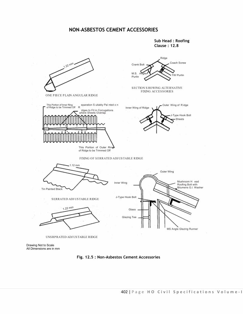
402 | P a g e H O C i v i l S p e c i f i c a t i o n s V o l u m e - I
NON-ASBESTOS CEMENT ACCESSORIES Sub Head : Roofing Clause : 12.8
Ridge
Crank Bolt
M.S. Angle Purlin
Coach Screw
TW Purlin
SECTION S HOWING ALTERNATIVE FIXING ACCESSORIES
ONE P IECE P LAIN ANGULAR RIDGE This Portion of Inner Ring eparation S uitably Pai nted o n of Ridge to be Trimmed Off R
Outer Wing of R idge Inner Wing of Ridge
idges to Fit in Corrugations where Sheets Overlap
J-Type Hook Bolt Sheets
This Portion of Outer Ring of Ridge to be Trimmed Off
FIXING OF S ERRATED ADJ US TABLE RIDGE 1.12 mm
Outer Wing
Tin Painted Black
SERRATED ADJ USTABLE RIDGE UNSRPRATED ADJ USTABLE RIDGE
Drawing Not to Scale All Dimensions are in mm
Inner Wing
J-Type Hook Bolt
Glass
Glazing Tee
Mushroom H ead Roofing Bolt with Bitumens G.I. Washer
MS Angle Glazing Runner
Fig. 12.5 : Non-Asbestos Cement Accessories

CPWD SPECIFICATIONS 2009 403 | Page HO Civil Specifications Volume - I
NON-ASBESTOS CEMENT GUTTERS
Sub Head : Roofing Clause : 12.9
VELLEY GUTTER BOUNDARY WALL GUTTER OREAVES GUTTER
HALF ROUND GUTTER
Nominal Size A T150 150 9.5250 250 9.5300 300 9.5
Nominal Size A B C D500X150X250 500 150 250 12.5450X150X300 450 150 300 12.5300X150X225 300 150 225 12.5275X125X175 275 125 175 10.0
Nominal Size A B C D900X200X225 900 200 225 12.5600X150X225 600 150 225 12.5450X125X150 450 125 150 12.5400X125X150 400 125 150 12.5
K
DROP END WITH SPIGOT
Type of Gutter Nominal Size A B C S K D150 150 90 240 70
250 200 200 300 100
300 200 200 300 100
125 150 90 240 70
Ogee Gutter 200 150 90 240 70FOR
HA
LF R
OU
ND
GU
TTER
B
AC D
BC
A
DA
T
S A A S
K
NOZZLE DROP END WITH SOCKET
K
B C B C
230
230215
215
290 290
D
S
190 310
NOZZLEANGLE FOR BOUNDARYWALL GUTTER
ANGLE FOR HALF ROUNDGUTTER
DROP END
S D
S
For B
ound
ary
Wal
l&
Val
ley
Gut
ter
S
D
105 90110 100115 150
105 90110 100105 90110 100115 150105 90110 100115 150105 90110 100105 90110 100115 150
Drawing Not to Scale All Dimensions are in mm
Fig. 12.6 : Non-Asbestos Cement Gutters
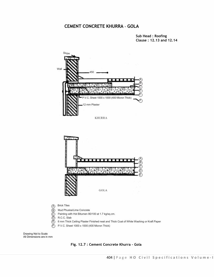
404 | P a g e H O C i v i l S p e c i f i c a t i o n s V o l u m e - I
CEMENT CONCRETE KHURRA - GOLA Sub Head : Roofing Clause : 12.13 and 12.14
Wall
450 A B C D E
P.V.C. Sheet 1000 x 1000 (400 Micron Thick) F
12 mm Plaster KHURRA
A B C D E
GOLA
A Brick Tiles
B Mud Phuska/Lime Concrete C Painting with Hot Bitumen 80/100 at 1.7 kg/sq.cm. D R.C.C. Slab E 6 mm Thick Ceiling Plaster Finished neat and Thick Coat of White Washing or Kraft Paper F P.V.C. Sheet 1000 x 1000 (400 Micron Thick)
Drawing Not to Scale All Dimensions are in mm
Fig. 12.7 : Cement Concrete Khurra - Gola

405 | P a g e H O C i v i l S p e c i f i c a t i o n s V o l u m e - I
6 m
m D
ia G
.I. S
heet
ing
B
olt 2
5 Lo
ng 35
36
60
HOLDER BAT CLAMP Sub Head : Roofing Clause : 12.23, 12.24
M.S. Holder Bat Clamp
1.6 Thick and 30 Wide Galvanised M.S. Clamp
Hook 275 Long and 10 dia of M.S. Bar Nut Bolt
Cement Concrete Block 1:2:4 (1 Cement : 2 C. Sand : 4 Stone Aggregate)
40 mm G.I. Bolt and Nut
C.I. Rain Water Pipe
Wall
Shoe
FRONT ELEVATION 100 Clearance
25
6 mm Dia Pin 100 12 mm Plaster
SECTION PLAN M.S. HOLDER BAT CLAMP FOR C.I. RAIN WATER PIPE
Cement Mortar
Wall
Cement Mortar 1:2
Bitumen Socket Spun Yarn
A.C. Rain Water Pipe
Screw Designation No. 18
SECTION ELEVATION
150
6 25 72
ELEVATION 25
22 6
6 20 Core Holes
16 Dia
10 72 132
M.S. Flat 3 mm thick Wooden Block
30
SECTION PLAN
Drawing Not to Scale All Dimensions are in mm
20 mm Wide DETAIL AT 'A'
5.5 Dia of Pipe 50 mm 80 mm 100 mm
'R' 30 mm 46 mm 58 mm
Note : The clamp shall be Galvanised throughout.
Fig. 12.8 : Holder Bat Clamp