Improved Efficiency Using Root Cause Failure … Efficiency Using Root Cause Failure Analysis Gerry...
9
Improved Efficiency Using Root Cause Failure Analysis Gerry Padnos Juki Automation Systems, Inc. Morrisville, NC Abstract A PCB fails final test. Why? Was it the solder paste? The screen printer? The PCB assembly machine? The reflow oven or none of the above? Unplanned downtime is a costly fact of life. In order to minimize the length of downtime it is necessary to have clear details on exactly what the source of the problem is, not just the symptoms. This information allows operators and maintenance personnel to go directly to take corrective steps more quickly and minimize downtime. There are many machines and materials involved in the assembly of a complete PCB; screen printers, conveyors, pick and place systems, reflow ovens, Automated Optical Inspection (AOI), solder paste and components. Some of this equipment has the ability to check its results before, during or immediately after it has completed its task. Until now there have been few real-time tools for the pick and place systems. In many cases, high speed movement on these machines makes it extremely hard to “see” exactly what is happening. Components misplaced by the assembly system could be caused by many different factors. Without tools to provide a clear view of very high speed placement, it is difficult to the cause of misplacement. How much easier would this task be if operators and maintenance personnel are armed with detailed information on the nozzles, feeders, and actual images of the picking and placing of parts on the PCB? This paper will discuss tools available for the placement machine to assist in root cause failure analysis (RCFA). Introduction Root cause failure analysis (RCFA) is the process of determining the source of a problem. In many industries, especially those involving complex machinery, it is common to use root cause failure analysis when problems occur. Why is RCFA so important? Efficiency and accuracy. When it comes to the complicated and expensive machines used in the PCB assembly process, downtime equals increased costs, lost profits, missed deliveries, lost opportunities or all of these. Better efficiency is one of the few ways to compete with lower labor cost manufacturers. With so many machines’ specifications looking so similar on paper, features that allow end users to improve efficiency in the production process are gaining importance in the selection process. The use of RCFA tools can assist in improving utilization, efficiency and maximizing profitability. Several systems to improve the production efficiency of the placement machine have been introduced over the years. There are tools designed for the direct improvement of utilization and indirect improvement. Twenty years ago, few pick and place machines had quick change feeder trolleys. Why were they invented? To improve efficiency so the operator could change from one product to another faster. Intelligent feeders help the operator setup feeder trolleys offline and reduce the need for “buddy system” reviews of the feeder setup. Splicing feeders and tray changers that can have parts replenished without stopping the machine also were created. All of these systems were designed to directly improve machine utilization and are now common in the industry. Other tools such as self-calibrations are indirect efficiency improvement tools. They reduce the chances of an error or the time needed for maintenance, but do not directly impact utilization. One thing these systems all have in common is that they are designed to improve the efficiency of the known or expected downtime. RCFA deals more with the unplanned downtime due to unknown or unexpected causes. A failure has occurred. The goal is to find the problem as quickly as possible and get the machine back into production. These tools can be separated into two categories also: after the fact and real time. After-the-fact tools include self-diagnostics that can be run after a problem occurs to see if a system is performing properly. Several tools exist to monitor machine performance in real-time such as tombstone detection and nozzle inspection, but these do not provide any insight into the cause of a problem. They only detect that there is a problem. Few systems exist to monitor the machine’s performance in real -time and provide useful As originally published in the IPC APEX EXPO Conference Proceedings.
Transcript of Improved Efficiency Using Root Cause Failure … Efficiency Using Root Cause Failure Analysis Gerry...

Improved Efficiency Using Root Cause Failure Analysis
Gerry Padnos
Juki Automation Systems, Inc.
Morrisville, NC
Abstract
A PCB fails final test. Why? Was it the solder paste? The screen printer? The PCB assembly machine? The reflow oven or
none of the above?
Unplanned downtime is a costly fact of life. In order to minimize the length of downtime it is necessary to have clear details
on exactly what the source of the problem is, not just the symptoms. This information allows operators and maintenance
personnel to go directly to take corrective steps more quickly and minimize downtime.
There are many machines and materials involved in the assembly of a complete PCB; screen printers, conveyors, pick and
place systems, reflow ovens, Automated Optical Inspection (AOI), solder paste and components. Some of this equipment has
the ability to check its results before, during or immediately after it has completed its task.
Until now there have been few real-time tools for the pick and place systems. In many cases, high speed movement on these
machines makes it extremely hard to “see” exactly what is happening. Components misplaced by the assembly system could
be caused by many different factors. Without tools to provide a clear view of very high speed placement, it is difficult to the
cause of misplacement.
How much easier would this task be if operators and maintenance personnel are armed with detailed information on the
nozzles, feeders, and actual images of the picking and placing of parts on the PCB?
This paper will discuss tools available for the placement machine to assist in root cause failure analysis (RCFA).
Introduction
Root cause failure analysis (RCFA) is the process of determining the source of a problem. In many industries, especially
those involving complex machinery, it is common to use root cause failure analysis when problems occur. Why is RCFA so
important? Efficiency and accuracy. When it comes to the complicated and expensive machines used in the PCB assembly
process, downtime equals increased costs, lost profits, missed deliveries, lost opportunities or all of these. Better efficiency is
one of the few ways to compete with lower labor cost manufacturers. With so many machines’ specifications looking so
similar on paper, features that allow end users to improve efficiency in the production process are gaining importance in the
selection process. The use of RCFA tools can assist in improving utilization, efficiency and maximizing profitability.
Several systems to improve the production efficiency of the placement machine have been introduced over the years. There
are tools designed for the direct improvement of utilization and indirect improvement. Twenty years ago, few pick and place
machines had quick change feeder trolleys. Why were they invented? To improve efficiency so the operator could change
from one product to another faster. Intelligent feeders help the operator setup feeder trolleys offline and reduce the need for
“buddy system” reviews of the feeder setup. Splicing feeders and tray changers that can have parts replenished without
stopping the machine also were created. All of these systems were designed to directly improve machine utilization and are
now common in the industry. Other tools such as self-calibrations are indirect efficiency improvement tools. They reduce
the chances of an error or the time needed for maintenance, but do not directly impact utilization. One thing these systems all
have in common is that they are designed to improve the efficiency of the known or expected downtime.
RCFA deals more with the unplanned downtime due to unknown or unexpected causes. A failure has occurred. The goal is
to find the problem as quickly as possible and get the machine back into production. These tools can be separated into two
categories also: after the fact and real time. After-the-fact tools include self-diagnostics that can be run after a problem
occurs to see if a system is performing properly. Several tools exist to monitor machine performance in real-time such as
tombstone detection and nozzle inspection, but these do not provide any insight into the cause of a problem. They only
detect that there is a problem. Few systems exist to monitor the machine’s performance in real-time and provide useful
As originally published in the IPC APEX EXPO Conference Proceedings.
information as to the cause of a problem. Unplanned downtime could be dramatically reduced with better root cause failure
analysis tools.
The key to improving efficiency when unplanned downtime occurs is root cause failure analysis; determining the exact
source of the problem. Knowing exactly what is causing a problem will allow maintenance personnel to focus their efforts
on a clear target rather than just following a checklist of possible problems. Many people have had the unpleasant, inefficient
experience of talking to phone tech support personnel who run down a checklist of “possible causes” for different problems.
But the reason the checklist is needed is that there is no data available about the root cause of the problem. Without knowing
the root cause of any problem, maintenance personnel are essentially working with blindfolds on. New systems designed
specifically to give better insight into problems can significantly reduce the time technicians need to spend diagnosing
problems, and improve equipment utilization.
Defect Prevention in Assembly Lines
One of the most common errors from the placement machine is missing or incorrectly placed components. There are two
main types of defect prevention systems found in typical assembly lines: systems built into a machine to check itself and
stand alone equipment whose sole function is to check for defects. An example of a system within a machine to check itself
would be post-print inspection on a screen printer. This system checks for defects after the printer has completed its task of
applying solder paste to the PWB. This “post print inspection” cannot say why there isn’t enough solder paste in a certain
location, only that there isn’t. Wouldn’t it be much more useful to know why there isn’t enough solder paste on the board?
Clogged apertures, dry paste, squeegee pressure and many more problems could be the cause. Similarly, typical placement
machines have several features to prevent defects, but most cannot provide insight as to why the defect occurred in the first
place. Vacuum sensors are commonly used to detect when a component falls off the nozzle or isn’t released on the board.
Lasers can check for tombstoning, dropped components, and even incorrect or damaged nozzles. But there are times within
the production cycle when these sensors cannot provide useful root cause information. If the vacuum sensor reports an error,
why did it occur? All the technician knows is that the required vacuum level was not achieved. Was the component not
aligned with the pick position? Is there a problem with the vacuum system? Is the nozzle damaged? Is the feeder feeding
correctly? Was the component even present at the pick position? All of these possibilities have to be considered, but each
takes time to evaluate.
An example of a machine that is used solely to check for defects would be an AOI or SPI machine. These systems all check
for problems that were caused by another machine in the line. They detect missing, incorrect or misplaced components,
satisfactory solder joints, etc. AOI machines provide very useful evaluation of the final PCB, but also have limitations. Like
the systems described above, they cannot tell why a component is missing or incorrectly placed. If an image shows a
component placed at the wrong angle, why did this happen? Was the feeder loaded incorrectly? Was the production program
written correctly? Was the component properly oriented in the tape, tube or tray? The images from AOI are only of the
results, not the process. In addition, typically there is only one AOI machine for the entire line so when a component is
missing, the operator doesn’t even know which placement machine should have placed the component. The key to
improving the efficiency of troubleshooting a missing or misplaced part is having actual images to see what happened during
the pick and place process.
Reasons for Failures
Focusing specifically on the placement machine, there are many reasons why a component may not be placed correctly on the
PCB:
Damaged nozzle,
Feeder malfunction,
Component incorrectly packaged (wrong orientation in feeder),
Incorrect pick position teaching,
Incorrect component data,
As originally published in the IPC APEX EXPO Conference Proceedings.
Improper board support, or
Components sticking to the nozzle
Due to the high speed of today’s placement systems, it is extremely difficult for an operator to know which of the above is
actually causing the problems. Therefore they are required to follow a pre-defined list of troubleshooting steps to eliminate
one possible cause after another. Throughout the process, they are completely unaware of the root cause. In the end, if they
haven’t found the problem, they just guess or use experience. This process is clearly imprecise and inefficient. Throughout
the troubleshooting period, the machine is down and the line is stopped.
The time required to precisely locate the source of the problem could be dramatically reduced through better RCFA tools.
One example is the use of simple pictures taken during the pick and placement process. Images of the various stages of the
pick and place process instantly show the technician what happened and where the problem came from. This is made
possible using tiny embedded high speed micro-cameras along with sophisticated image analysis. Along with the visual
analysis by the technician, the software can provide automatic alerts when an error occurs and perform some RCFA on its
own.
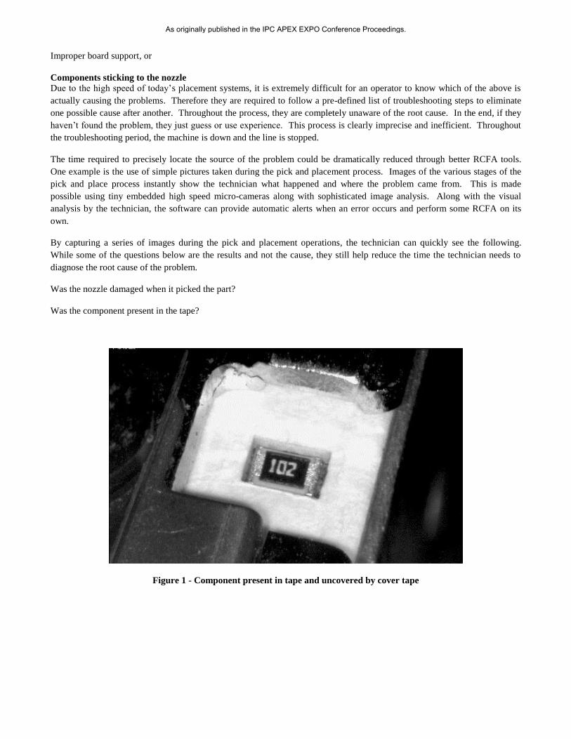
By capturing a series of images during the pick and placement operations, the technician can quickly see the following.
While some of the questions below are the results and not the cause, they still help reduce the time the technician needs to
diagnose the root cause of the problem.
Was the nozzle damaged when it picked the part?
Was the component present in the tape?
Figure 1 - Component present in tape and uncovered by cover tape
As originally published in the IPC APEX EXPO Conference Proceedings.
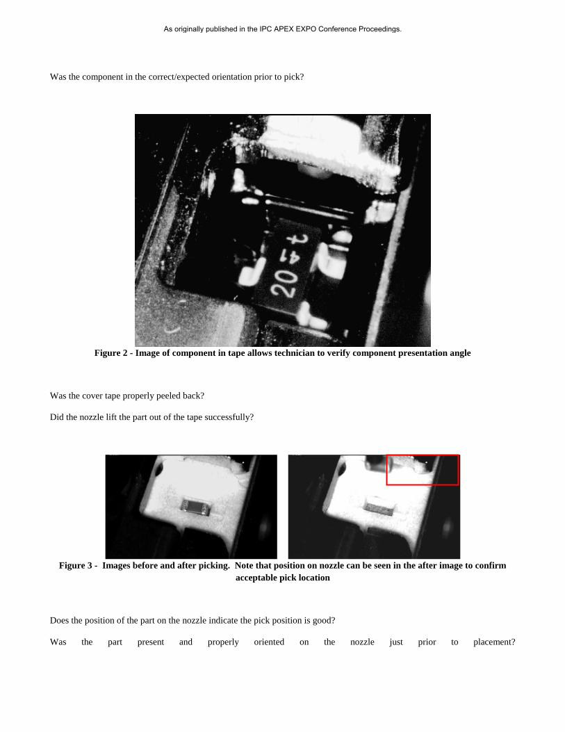
Was the component in the correct/expected orientation prior to pick?
Figure 2 - Image of component in tape allows technician to verify component presentation angle
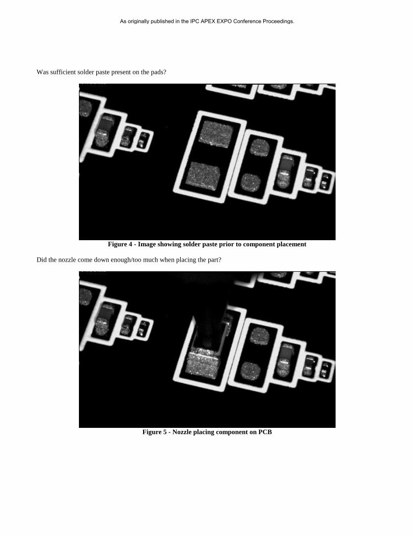
Was the cover tape properly peeled back?
Did the nozzle lift the part out of the tape successfully?
Figure 3 - Images before and after picking. Note that position on nozzle can be seen in the after image to confirm
acceptable pick location
Does the position of the part on the nozzle indicate the pick position is good?
Was the part present and properly oriented on the nozzle just prior to placement?
As originally published in the IPC APEX EXPO Conference Proceedings.
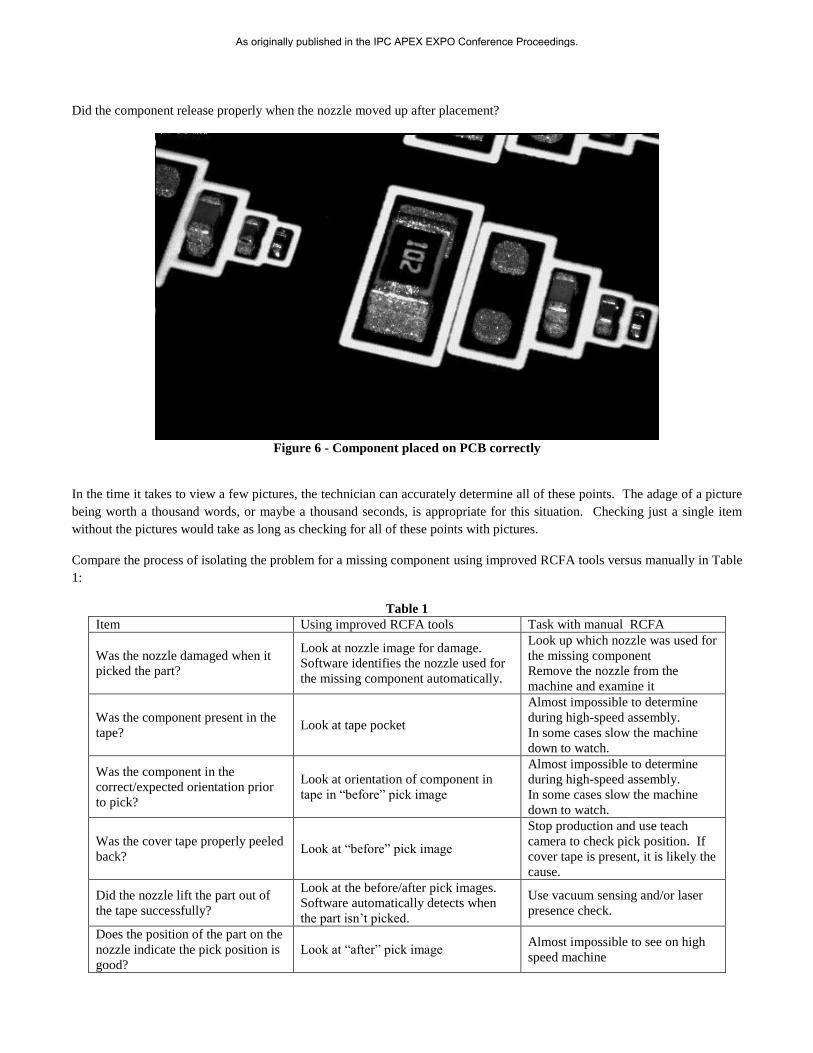
Was sufficient solder paste present on the pads?
Figure 4 - Image showing solder paste prior to component placement
Did the nozzle come down enough/too much when placing the part?
Figure 5 - Nozzle placing component on PCB
As originally published in the IPC APEX EXPO Conference Proceedings.
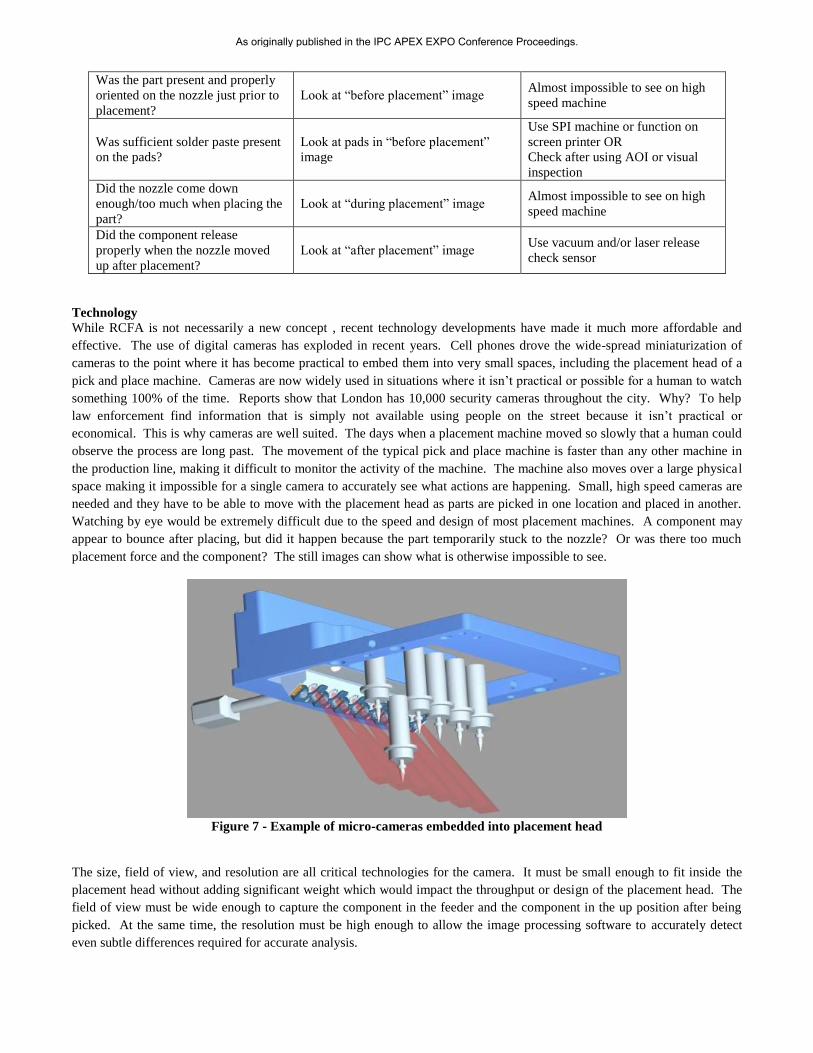
Did the component release properly when the nozzle moved up after placement?
Figure 6 - Component placed on PCB correctly
In the time it takes to view a few pictures, the technician can accurately determine all of these points. The adage of a picture
being worth a thousand words, or maybe a thousand seconds, is appropriate for this situation. Checking just a single item
without the pictures would take as long as checking for all of these points with pictures.
Compare the process of isolating the problem for a missing component using improved RCFA tools versus manually in Table
1:
Table 1
Item Using improved RCFA tools Task with manual RCFA
Was the nozzle damaged when it
picked the part?
Look at nozzle image for damage.
Software identifies the nozzle used for
the missing component automatically.
Look up which nozzle was used for
the missing component
Remove the nozzle from the
machine and examine it
Was the component present in the
tape? Look at tape pocket
Almost impossible to determine
during high-speed assembly.
In some cases slow the machine
down to watch.
Was the component in the
correct/expected orientation prior
to pick?
Look at orientation of component in
tape in “before” pick image
Almost impossible to determine
during high-speed assembly.
In some cases slow the machine
down to watch.
Was the cover tape properly peeled
back? Look at “before” pick image
Stop production and use teach
camera to check pick position. If
cover tape is present, it is likely the
cause.
Did the nozzle lift the part out of
the tape successfully?
Look at the before/after pick images.
Software automatically detects when
the part isn’t picked.
Use vacuum sensing and/or laser
presence check.
Does the position of the part on the
nozzle indicate the pick position is
good?
Look at “after” pick image Almost impossible to see on high
speed machine
As originally published in the IPC APEX EXPO Conference Proceedings.
Was the part present and properly
oriented on the nozzle just prior to
placement?
Look at “before placement” image Almost impossible to see on high
speed machine
Was sufficient solder paste present
on the pads?
Look at pads in “before placement”
image
Use SPI machine or function on
screen printer OR
Check after using AOI or visual
inspection
Did the nozzle come down
enough/too much when placing the
part?
Look at “during placement” image Almost impossible to see on high
speed machine
Did the component release
properly when the nozzle moved
up after placement?
Look at “after placement” image Use vacuum and/or laser release
check sensor
Technology
While RCFA is not necessarily a new concept , recent technology developments have made it much more affordable and
effective. The use of digital cameras has exploded in recent years. Cell phones drove the wide-spread miniaturization of
cameras to the point where it has become practical to embed them into very small spaces, including the placement head of a
pick and place machine. Cameras are now widely used in situations where it isn’t practical or possible for a human to watch
something 100% of the time. Reports show that London has 10,000 security cameras throughout the city. Why? To help
law enforcement find information that is simply not available using people on the street because it isn’t practical or
economical. This is why cameras are well suited. The days when a placement machine moved so slowly that a human could
observe the process are long past. The movement of the typical pick and place machine is faster than any other machine in
the production line, making it difficult to monitor the activity of the machine. The machine also moves over a large physical
space making it impossible for a single camera to accurately see what actions are happening. Small, high speed cameras are
needed and they have to be able to move with the placement head as parts are picked in one location and placed in another.
Watching by eye would be extremely difficult due to the speed and design of most placement machines. A component may
appear to bounce after placing, but did it happen because the part temporarily stuck to the nozzle? Or was there too much
placement force and the component? The still images can show what is otherwise impossible to see.
Figure 7 - Example of micro-cameras embedded into placement head
The size, field of view, and resolution are all critical technologies for the camera. It must be small enough to fit inside the
placement head without adding significant weight which would impact the throughput or design of the placement head. The
field of view must be wide enough to capture the component in the feeder and the component in the up position after being
picked. At the same time, the resolution must be high enough to allow the image processing software to accurately detect
even subtle differences required for accurate analysis.
As originally published in the IPC APEX EXPO Conference Proceedings.
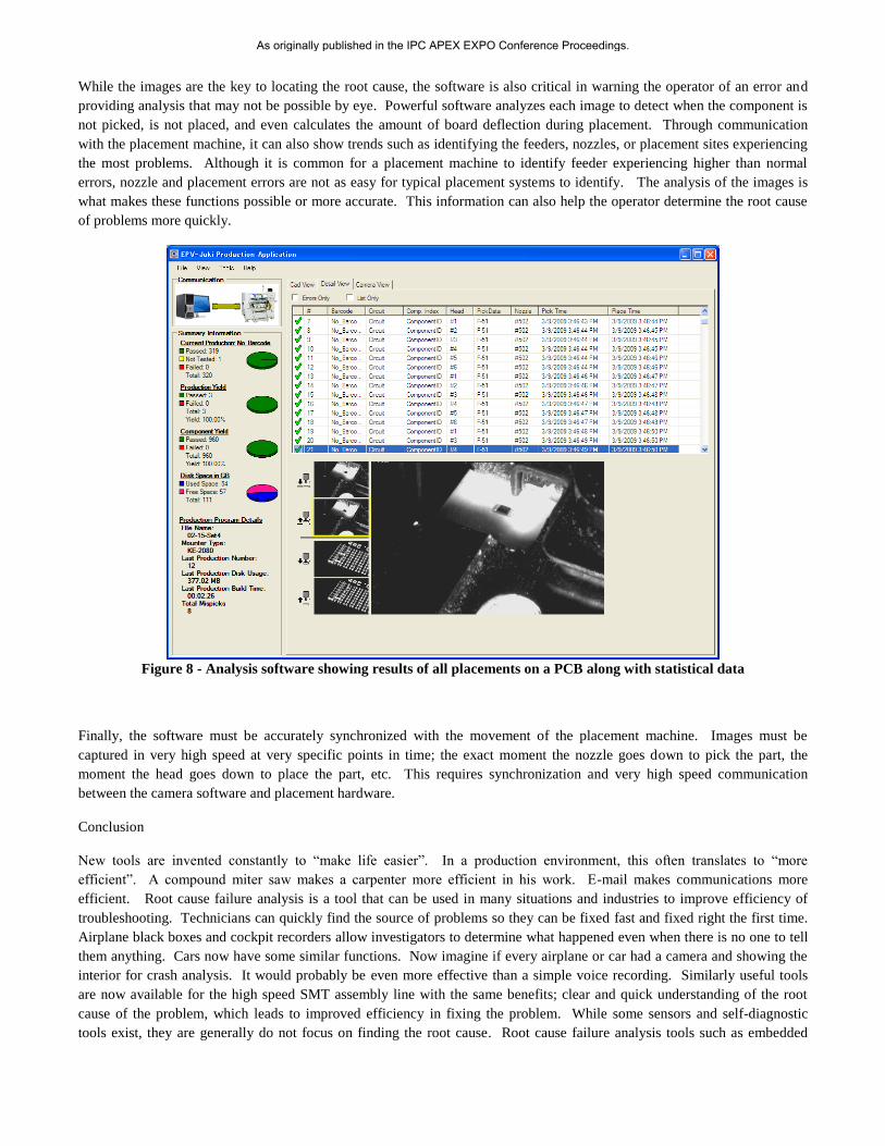
While the images are the key to locating the root cause, the software is also critical in warning the operator of an error and
providing analysis that may not be possible by eye. Powerful software analyzes each image to detect when the component is
not picked, is not placed, and even calculates the amount of board deflection during placement. Through communication
with the placement machine, it can also show trends such as identifying the feeders, nozzles, or placement sites experiencing
the most problems. Although it is common for a placement machine to identify feeder experiencing higher than normal
errors, nozzle and placement errors are not as easy for typical placement systems to identify. The analysis of the images is
what makes these functions possible or more accurate. This information can also help the operator determine the root cause
of problems more quickly.
Figure 8 - Analysis software showing results of all placements on a PCB along with statistical data
Finally, the software must be accurately synchronized with the movement of the placement machine. Images must be
captured in very high speed at very specific points in time; the exact moment the nozzle goes down to pick the part, the
moment the head goes down to place the part, etc. This requires synchronization and very high speed communication
between the camera software and placement hardware.
Conclusion
New tools are invented constantly to “make life easier”. In a production environment, this often translates to “more
efficient”. A compound miter saw makes a carpenter more efficient in his work. E-mail makes communications more
efficient. Root cause failure analysis is a tool that can be used in many situations and industries to improve efficiency of
troubleshooting. Technicians can quickly find the source of problems so they can be fixed fast and fixed right the first time.
Airplane black boxes and cockpit recorders allow investigators to determine what happened even when there is no one to tell
them anything. Cars now have some similar functions. Now imagine if every airplane or car had a camera and showing the
interior for crash analysis. It would probably be even more effective than a simple voice recording. Similarly useful tools
are now available for the high speed SMT assembly line with the same benefits; clear and quick understanding of the root
cause of the problem, which leads to improved efficiency in fixing the problem. While some sensors and self-diagnostic
tools exist, they are generally do not focus on finding the root cause. Root cause failure analysis tools such as embedded
As originally published in the IPC APEX EXPO Conference Proceedings.

micro cameras to show the exact details of the pick and place process along with powerful analysis software can save a huge
amount of time versus methods commonly used today and dramatically increase efficiency and equipment utilization.
As originally published in the IPC APEX EXPO Conference Proceedings.


![7 Root Cause Failure Analysis Rev 2 Tcm4-367879[1]](https://static.fdocuments.in/doc/165x107/577d25ca1a28ab4e1e9f97d8/7-root-cause-failure-analysis-rev-2-tcm4-3678791.jpg)