ROOT CAUSE FAILURE INVESTIGATION OF …eprints.utem.edu.my/16559/1/Root Cause Failure Investigation...
24
SUPERVISOR DECLARATION “I hereby declare that I have read this thesis and in my opinion this thesis is sufficient in terms of scope and quality for the award of the degree of Bachelor of Mechanical Engineering (Plant and Maintenance) with honours” Signature : ................................... Supervisor : DR. MOHD YUSOFF BIN SULAIMAIN Date :
Transcript of ROOT CAUSE FAILURE INVESTIGATION OF …eprints.utem.edu.my/16559/1/Root Cause Failure Investigation...

SUPERVISOR DECLARATION
“I hereby declare that I have read this thesis and in my opinion this thesis is
sufficient in terms of scope and quality for the award of the degree of Bachelor of
Mechanical Engineering (Plant and Maintenance) with honours”
Signature : ...................................
Supervisor : DR. MOHD YUSOFF BIN SULAIMAIN
Date :
ii
DECLARATION
“I hereby declare that the work in this thesis is my own except for summaries and
quotations which have been duly acknowledged”
Signature : ...................................
Author : MOHAD KHALIL BIN MOHAD KHAZIN
Date :

iii
SPECIAL THANKS TO
MOTHER AND FATHER
FOR THE SUPPORTS AND ADVICES
iv
ACKNOWLEDGEMENT
First of all, I am grateful to ALLAH S.W.T. for establishing me to complete
this research and report.
I wish to express my sincere thanks to my family for their unceasing
encouragement and support in all aspect.
I place on record, my sincere gratitude to my supervisor, Dr Mohd Yusoff
Bin Sulaiman. I am extremely grateful and indebted to him for his expert, sincere and
valuable guidance and encouragement extended to me.
I take this opportunity to record my sincere thanks to all faculty members of
the Department of Plant and Maintenance, UTeM for their help and providing me
with all the necessary facilities.
I also place on record, my sense of gratitude to one and all who, directly or
indirectly, have lent their helping hand in this venture.
v
ABSTRACT
Failure analysis of structures has gained a considerable interest in many
engineering areas. The aim of this research is to determine the root cause of the
structural failures which can reduce the failure risks and prevent similar failures in
the future. This thesis presents experimental investigations for the failure of a super-
heater tube of a coal-fired power plant using several failure analysis procedures. The
failure analysis comprised of visual inspection, optical microscopic, ultrasonic
thickness measurement test and hardness test. A sample of a total-fractured super-
heater tube obtained from an industry was used in this investigation. Initial visual
investigations found that the super-heater tube had a longitudinal crack. This fracture
appearance is called fish mouth stress rupture. The ultrasonic thickness test is to
detect a significant oxide layer that occurs in the steam side surface. The optical
microscopy were used to identify intergranular cracks, voids, elongated grain and
deposit layers. The hardness test is to determine the resistance of material to
penetration after being heated. The results for the hardness test and ultra-thickness
test used to determine the rupture temperature and estimate the life period of the fail
tube using Larson Miller Parameter.

vi
ABSTRAK
Analisis kegagalan struktur telah menjadi satu keutamaan dalam bidang
kejuruteraan. Tujuan kajian ini adalah untuk menentukan punca kepada kegagalan
struktur yang boleh mengurangkan risiko kegagalan dan mengelakkan kegagalan
yang serupa pada masa hadapan. Tesis ini menceritakan tentang uji kaji terhadap
kegagalan tiub pemanas loji janakuasa arang batu menggunakan beberapa prosedur
analisis kegagalan. Analisis kegagalan terdiri daripada pemeriksaan visual,
mikroskopik optik, ujian ultrasonik pengukuran ketebalan dan ujian kekerasan. Satu
sampel tiub pemanas yang diperolehi daripada industri telah digunakan dalam
penyiasatan ini. Siasatan awal iaitu pemeriksaan visual mendapati tiub pemanas
mempunyai retak. Ini menunjukkan kegagalan yg telah berlaku pada tiub pemanas
dipanggil “fish mouth stress rupture”. Ujian ultrasonik pengukuran ketebalan adalah
untuk mengesan lapisan oksida yang berlaku di permukaan tiub di sebelah luaran.
The mikroskop optik telah digunakan untuk mengenal pasti kegagalan sejenis
“intergranular cracks”, “voids”, “elongated grain” dan “deposit layers”. Ujian
kekerasan adalah untuk menentukan ketahanan bahan untuk penembusan selepas
dipanaskan. Keputusan bagi ujian kekerasan dan ujian ultrasonic pengukuran
ketebalan telah digunakan untuk menentukan suhu pecah dan anggaran tempoh hayat
tiub gagal menggunakan “Larson Miller Parameter”.

vii
TABLE OF CONTENT
CHAPTER CONTENT PAGE
DECLARATION ii
DEDICATION iii
ACKNOWLEDGEMENT iv
ABSTRACT v
ABSTRAK vi
TABLE OF CONTENT vii
LIST OF TABLES x
LIST OF FIGURES xi
LIST OF APPENDIX xii
CHAPTER I INTRODUCTION 1
1.1 BACKGROUND 1
1.2 PROBLEM STATEMENT 2
1.3 OBJECTIVE 3
CHAPTER II LITERATURE REVIEW 4
2.1 BOILER 5
2.1.1 Fire Tube Boiler 5
2.1.2 Water Tube Boiler 5
2.2 BOILER SUPERHEATER TUBE 7
2.2.1 Electric Resistance Weld Tube 8

viii
CHAPTER CONTENT PAGE
2.2.2 Seamless Tube 9
2.2.3 Alloys in Super-Heater Tube Material 10
2.3 DEFINITION OF FAILURE ANALYSIS 11
2.4 BOILER SUPERHEATER TUBE LEAK OR
FAILURE
13
2.4.1 Flue Gas Erosion (Outside Tube) 13
2.4.2 Pitting Corrosion or Oxygen
Corrosion (Inside Tube)
14
2.4.3 Thermal Fatigue 14
2.4.4 Short Term Overheating 15
2.4.5 Steam Cutting 16
2.4.6 Coal Ash Corrosion 17
2.4.7 Hydrogen Damage 18
2.5 LARSON MILLER PARAMETER 18
2.6 CREEP 19
CHAPTER III METHODOLOGY 20
3.1 INTRODUCTION 20
3.2 FLOWCHART OF THE RESEARCH 21
3.3 VISUAL INSPECTION 22
3.4 ULTRASONIC THICKNESS
MEASUREMENT
22
3.5 SAMPLE PREPARATIONS 23
3.5.1 Sectioning 23
3.5.2 Mounting 24
3.5.3 Grinding and Polishing Procedure 24
3.5.4 Etching 25
3.6 METALLOGRAPHIC EXAMINATION 25
3.7 HARDNESS TEST 25
3.7.1 Vickers Hardness Test 26
3.8 CREEP ANALYSIS 28
3.9 OXIDE SCALE THICKNESS 29
ix
CHAPTER CONTENT PAGE
CHAPTER IV RESULTS AND ANALYSIS 30
4.1 INTRODUCTION 30
4.2 VISUAL INSPECTION 30
4.3 ULTRASONIC THICKNESS
MEASUREMENT
31
4.4 HARDNESS TESTING RESULTS 32
4.5 LARSON-MILLER PARAMETER
ANALYSIS
34
4.5.1 Temperature Calculation Using Metal
Thickness
34
4.5.2 Temperature Calculation Using Oxide
Scale Thickness
35
4.5.3 Temperature Calculation Using Metal
Hardness
39
4.6 MICROSTRUCTURE EVALUATION 39
4.7 LIFE EXPECTANCY STUDY 43
4.8 RESULT ANALYSIS 45
CHAPTER V CONCLUSION AND RECOMMENDATION 46
5.1 CONCLUSION 46
5.2 RECOMMENDATION 47
BIBLIOGRAPHY 49
APPENDIX 52
APPENDIX A 53
APPENDIX B 54
APPENDIX C 55
APPENDIX D 56
APPENDIX E 57

x
LIST OF TABLES
TABLE TITLE PAGE
2.1 Water tube boiler versus fire tube boiler 7
2.2 Specification in general use for boiler tube (ASTM International, 2014) 9
2.3 Feritic alloys used in boiler tube (ASTM international, 2014) 10
2.4 Functions of alloying element (Chase Alloys Ltd, 2011) 11
4.1 Thickness measurement result 32
4.2 Vickers Hardness result from the tube sample 33
4.3 Summarized Spheroidization classed 40
4.4 Sample microstructure results (current research) 42
4.5 Estimated life of the failed tube 43

xi
LIST OF FIGURES
FIGURE TITLE PAGE
2.1 Simple process of boiler fire tubes (IHS Engineering 360, 2014) 5
2.2 Simple process boiler water tubes (IHS Engineering 360, 2014) 6
2.3 Super-heater tubes in boiler (Chong, Ahmad, & Purbolaksono, 2002) 8
2.4 Pitting corrosion attack (Chong, Ahmad, & Purbolaksono, 2002) 14
2.5 Bursting tubes (Chong, Ahmad, & Purbolaksono, 2002) 16
2.6 Steam cutting affected tube (Chong, Ahmad, & Purbolaksono, 2002) 16
2.7 Steam cutting affected tube (Chong, Ahmad, & Purbolaksono, 2002) 17
2.8 Coal ash corrosion tubes (Chong, Ahmad, & Purbolaksono, 2002) 17
2.9 Creep cavities at rupture regions (Chong, Ahmad, & Purbolaksono, 2002) 19
3.1 Research flowchart 21
3.2 Vickers hardness test 27
3.3 The residual indent on the surface 27
4.1 Sample of the boiler super-heater tube 31
4.2 Cross-sectional area of the tube that are being measured using UT test 32
4.3 Graph metal temperature VS oxide scale thickness 37
4.4 Graph rupture time VS scale thickness 38
4.5 Normal metal structures for carbon steel (current research) 41
4.6 Boiler tube metal temperature vs. rupture time 44
xii
LIST OF APPENDIX
APPEDICES TITLE PAGE
A Graph Hoop Stress VS Larson Miller Parameter 53
B Material Grade and Properties 54
C Boiler Tube Specification 55
D Boiler Tube Grade for Tenaga Nasional Berhad (TNB) Power Plant 56
E External View of Kapar Energy Ventures (KEV) 57

1
CHAPTER 1
INTRODUCTION
1.1 BACKGROUND
Kapar Energy Venture or also known Stesen Janaelektrik Sultan Salahuddin
Abdul Aziz a subsidiary of Tenaga Nasional Berhad (TNB) located in Kapar Klang
Selangor. This plant is the largest power producer in Malaysia with triple type of fuel
which is gas, oil and coal for primary fuel. The 2420 MW power produced were from
four generating facilities or phases.
Phase 1: Consist of 2 units with 300 MW capacities and can use natural gas
or bunker oil for primary fuel. Operation started in 1981 and thermal plant type
consisting of a boiler and a turbine. The boiler manufactured by Riley Mitsui Japan
and the turbine from Mitsubishi Heavy Industry Japan.
Phase 2: Consist of 2 units with 300MW capacity power and can use natural
gas, bunker oil or coal for primary fuel. Operation started 1985 and thermal plant
2
type consisting of a boiler and a turbine. The boiler manufactured by Ishigawa Heavy
Industry Japan and turbine from Mitsubishi Heavy Industry Japan.
Phase 3: Consist of 2 units with 500 MW capacity power and can use natural
gas, bunker oil and coal for primary fuel. Operation started in 1995 and thermal plant
type consisting of a boiler and a turbine. The boiler manufactured by Ishigawa Heavy
Industry Japan and turbine by General Electric.
Phase 4: Consist 2 units with 100MW capacity power and can use natural gas
or distillate oil for fuel. Started operation in 1994 and gas turbine open cycle type.
All systems manufactured by Nouvo Pignone GE.
Defective boiler tube can affect the operation process at this plant because
boiler tubes are very important component in boiler system. Boiler tube is energy
conversion component where heat energy from combustion of fuel are absorbed by
the tubes and transferred to the water to produce steam. Heat energy is obtained from
combustion gas. The combustion gas will evaporate the water into steam in the water
wall tubes and there after passes over to the super-heater tube to produce super-
heated steam. The boiler tubes were designed for a specific period of time of
operation in a complex situation involving high temperature, pressure and corrosive
environment.
1.2 PROBLEM STATEMENT
The function of boiler is to convert water to steam. In high capacity power
generation industry, water tube boilers were used to absorb thermal energy from
burning of fuel such as coal. Coal fuelled boiler dominates the electric power plant
by providing superheated steam to drive the steam turbine. In a coal fire with fire

3
tube type boiler, the super-heater tube is exposed to high temperature flue gas to
1000 °C. A boiler at Kapar Energy Venture SDN BHD power plant was shut down
due to final super-heater tube failure with running hours of 40258. The type of failure
has been detected was tube burst. There were no sign of significant corrosion or
erosion to the tube. The tube also shows no indication suffering from creep.
1.3 PROJECT OBJECTIVE
The shutdown of a power plant is a major event. When it is scheduled, all
maintenance procedure focuses on shortening the period of shutdown. Unscheduled
shut-down is disruptive and costly. While the causes of failures have been
documented by the manufacturer, the root of these failures can be due to localised
irregularities. It is therefore very sensible to transform this industrial problem as a
project with the following objective:
To investigate the root cause failure (tube burst) of final super heater tube.
To suggest a new maintenance procedure to avoid failure
4
CHAPTER 2
LITERRATURE REVIEW
2.1 BOILER
By definition, steam generator or a boiler is a closed pressure vessel in which
a water is heated by combustion and being converted into steam for heating purpose
or as a mobile power source (Harry Jr, 1981). A boiler is also known as a tool to
convert the chemical energy in the fuel to heat energy and from heat energy to
potential energy available in the steam. In the modern world where power generation
is an absolute must and a need to be produced at astronomical quantities, boiler
becomes an important tool due to its capabilities to generate steam from relatively
cheap and easily available entity, water. Steam is important for power generating
facilities because it can be produced anywhere in the world as long as there are fuel
as the heat source in the area because of steam is produced from water and it is non-
toxic and also can be recycled from steam to water to steam again by the use of a
condenser. Today boiler is engineered to used steam efficiently as well economically
feasible. Boiler can be divided by two major type, fire tube boiler and water tube
boiler. Boiler can be operated using two important elements, fuel and water.

5
2.1.1 Fire Tube Boiler
A fire tube boiler is a type of boiler in which hot gases from a fire pass
through one or more tubes running through a sealed container of water, Figure 2.1.
The heat of the gases is transferred through the wall of the tube by thermal
conduction, heating the water and ultimately creating a steam (Harry Jr, 1981).
Figure 2.1 : Simple process of boiler fire tubes (IHS Engineering 360, 2014)
2.1.2 Water Tube Boiler
A water tube boiler is a type of boiler which water circulates in tubes heated
externally by the fire. Fuel is burned inside the furnace, creating hot gas which heats
water in the steam generating tube (Harry Jr, 1981). In smaller boilers, additional
generating tubes are separate in the furnace, while larger utility boilers rely on the
water filled tubes that make up the walls of the furnace to generate steam. The heated
water then rises into the steam drum. Here, saturated steam is drawn off the top of

6
the drum. In some service, the steam will recycle the furnace through super-heater
tubes to become superheated. Figure 2.2 shows a simple process in water tube boiler.
Figure 2.2 : Simple process boiler water tubes (IHS Engineering 360, 2014)
Fire tube boilers are designed with the tubes contained in the shell. The tubes
of most water tube boiler are located outside the shell or drum. The advantage to this
feature of the water tube boiler is a higher capacity may be obtained by increasing
the number of tube independent of shell. The biggest advantage over fire tube boiler
is the freedom to increase the capacities and pressure. The advantage and
disadvantage of boiler water tube are showing in Table 2.1 compared with boiler fire
tube. The ability of water tube boiler to generate superheated steam makes these
boiler particularly attractive in application that require dry, high pressure, high
energy steam including steam turbine power generation. Owing to their superb
working properties, the use of water tube boiler is highly preferred in most power
generating plants.

7
Table 2.1 : Water tube boiler versus fire tube boiler
No. WATER TUBE BOILER FIRE TUBE BOILER
1. The water circulate inside tube Water circulate outside the tube
2. Can generate pressure up to 165 Bar Only pressure up to 25 Bar
3. Can generate steam up to 450 mt/hr Only generate up to 10mt/hr
4. Overall efficiency up to 90% Overall efficiency 75%
5. Various part can be separated Erection is difficult
6. High operation cost Low operation cost
7. Various type of fuel can be use Only can use manufacturing design fuel
8. The bursting chances are more Bursting chances are less
9. Use for large power plant Not suitable for power plant
10. Easy to done maintenance Not easy to done maintenance
2.2 BOILER SUPERHEATER TUBE
Super-heater tubes are a bank of tubes in the exhaust gas duct after the boiler
combustion and use to heat the steam above the saturation temperature (Harry Jr,
1981). Boiler super-heater tubes are energy conversion high pressure and
temperature component in a boiler system. It is used to convert wet steam to dry
steam which is at high pressure, superheated steam, then delivered to a turbine for
generate electrical power in the power plant such as a Tenaga National Power Plant
at Kapar, Klang. Heat energy is obtained from combustion gases produced by
burning coal in the furnace. The flue gases evaporate wet steam into superheated
steam in the super-heater tube bundle. The tubes designed for a specific period of
time operated in a complex situation involving high temperature, pressure and
corrosive environment. Figure 2.3 shows a bank of tube in boiler water tube at flue
gas compartment.

8
Figure 2.3 : Super-heater tubes in boiler (Chong, Ahmad, & Purbolaksono, 2002)
2.2.1 Electric Resistance Weld Tube
Boiler super-heater tube is made in both seamless and electric resistance
weld. Tubing made by either process is rigidly controlled and tested both during and
after rolling to meet the exacting specification requirement of a pressure tube and
environment condition (Chong, Ahmad, & Purbolaksono, 2002). Boiler tube have to
comply with specification and meet allowable working pressure rating, are always
expressed and sold as minimum wall. Whether to use seamless or electric weld boiler
tube is largely a matter of personal preference. Electric weld boiler tubes are fully
comparable to seamless by standard of ASME Boiler & Pressure Vessel code
requirement and general acceptance.

9
2.2.2 Seamless Tube
Advocates of seamless tubing prefer no weld seam in the tube wall. This is
true as a further protection in the heavier nominal of seamless due to the method of
manufacture. Further, the piercing process in making seamless tube impart a tough
mill scale to tube surface which appears to make it more resistance to corrosion.
Specification in general use for boiler tube is showing in Table 2.2.
Table 2.2 : Specification in general use for boiler tube (ASTM International, 2014)
GRADE SPECIFICATION
Low carbon seamless A-192 / A-179
Low carbon electric weld A-178 / A-214 / A-226
Medium carbon seamless A-210
Medium carbon electric weld A-178
Low alloy A-423
Carbon molly seamless A-209
Carbon moly electric weld A-250
Alloy seamless A-213 T series
Stainless seamless A-213 TP series
Stainless electric weld A-249 TP series
10
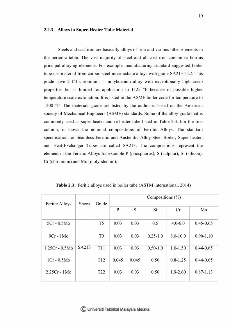
2.2.3 Alloys in Super-Heater Tube Material
Steels and cast iron are basically alloys of iron and various other elements in
the periodic table. The vast majority of steel and all cast iron contain carbon as
principal alloying elements. For example, manufacturing standard suggested boiler
tube use material from carbon steel intermediate alloys with grade SA213-T22. This
grade have 2-1/4 chromium, 1 molybdenum alloy with exceptionally high creep
properties but is limited for application to 1125 °F because of possible higher
temperature scale exfoliation. It is listed in the ASME boiler code for temperature to
1200 °F. The materials grade are listed by the author is based on the American
society of Mechanical Engineers (ASME) standards. Some of the alloy grade that is
commonly used as super-heater and re-heater tube listed in Table 2.3. For the first
column, it shows the nominal compositions of Ferritic Alloys. The standard
specification for Seamless Ferritic and Austenitic Alloy-Steel Boiler, Super-heater,
and Heat-Exchanger Tubes are called SA213. The compositions represent the
element in the Ferritic Alloys for example P (phosphorus), S (sulphur), Si (silicon),
Cr (chromium) and Mo (molybdenum).
Table 2.3 : Feritic alloys used in boiler tube (ASTM international, 2014)
Feritic Alloys Specs Grade Compositions (%)
P S Si Cr Mo
5Cr - 0.5Mo
SA213
T5 0.03 0.03 0.5 4.0-6.0 0.45-0.65
9Cr - 1Mo T9 0.03 0.03 0.25-1.0 8.0-10.0 0.90-1.10
1.25Cr - 0.5Mo T11 0.03 0.03 0.50-1.0 1.0-1.50 0.44-0.65
1Cr - 0.5Mo T12 0.045 0.045 0.50 0.8-1.25 0.44-0.65
2.25Cr - 1Mo T22 0.03 0.03 0.50 1.9-2.60 0.87-1.13
11
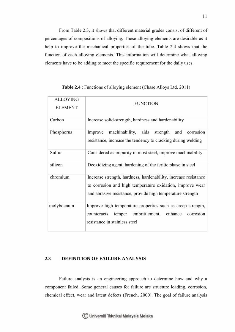
From Table 2.3, it shows that different material grades consist of different of
percentages of compositions of alloying. These alloying elements are desirable as it
help to improve the mechanical properties of the tube. Table 2.4 shows that the
function of each alloying elements. This information will determine what alloying
elements have to be adding to meet the specific requirement for the daily uses.
Table 2.4 : Functions of alloying element (Chase Alloys Ltd, 2011)
ALLOYING
ELEMENT FUNCTION
Carbon Increase solid-strength, hardness and hardenability
Phosphorus Improve machinability, aids strength and corrosion
resistance, increase the tendency to cracking during welding
Sulfur Considered as impurity in most steel, improve machinability
silicon Deoxidizing agent, hardening of the feritic phase in steel
chromium Increase strength, hardness, hardenability, increase resistance
to corrosion and high temperature oxidation, improve wear
and abrasive resistance, provide high temperature strength
molybdenum Improve high temperature properties such as creep strength,
counteracts temper embrittlement, enhance corrosion
resistance in stainless steel
2.3 DEFINITION OF FAILURE ANALYSIS
Failure analysis is an engineering approach to determine how and why a
component failed. Some general causes for failure are structure loading, corrosion,
chemical effect, wear and latent defects (French, 2000). The goal of failure analysis
12
is to understand the root cause of the failure so as to prevent similar failure in the
future. In modern business analysis, it is very important due to involve with
economic issues.
To verify the failure mode, it is important to determine the factor that explain
the how and why the failure occurred such as identifying the root cause event of the
failures in super-heated boiler system. The root cause event allows us to explain why
the component failed. Many steps need to be followed to determine and carry out an
investigation.
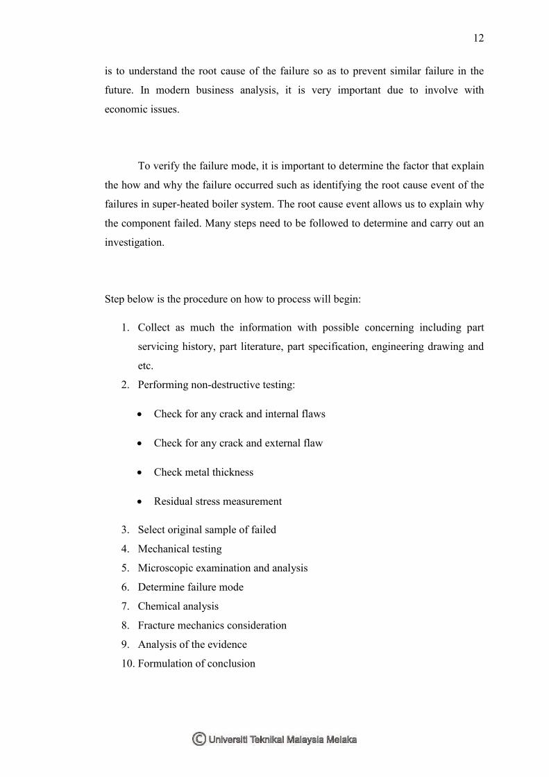
Step below is the procedure on how to process will begin:
1. Collect as much the information with possible concerning including part
servicing history, part literature, part specification, engineering drawing and
etc.
2. Performing non-destructive testing:
Check for any crack and internal flaws
Check for any crack and external flaw
Check metal thickness
Residual stress measurement
3. Select original sample of failed
4. Mechanical testing
5. Microscopic examination and analysis
6. Determine failure mode
7. Chemical analysis
8. Fracture mechanics consideration
9. Analysis of the evidence
10. Formulation of conclusion