Importance of 4D simulation, Planning, and delivery · 2014-06-26 · Importance of 4D simulation,...
56
Importance of 4D simulation, Planning, and delivery Krishni Wijesooriya, PhD University of Virginia
Transcript of Importance of 4D simulation, Planning, and delivery · 2014-06-26 · Importance of 4D simulation,...
Importance of 4D simulation, Planning, and delivery
Krishni Wijesooriya, PhDUniversity of Virginia

Learning Objectives
• To understand the physiological characteristics of tumor motion in different treatment sites.
• To understand the available technology for 4D planning in SRT.
• To understand startegies for employing ITV and MIPs for dose calculations.

Motivation
Capture the 4th dimension accuratelyDeliver the intended plan dose to the tumorMinimize healthy tissue toxicity -> escalate dose to tumor
Safety Margins

Compliments of Paul Keall
Gold Standard
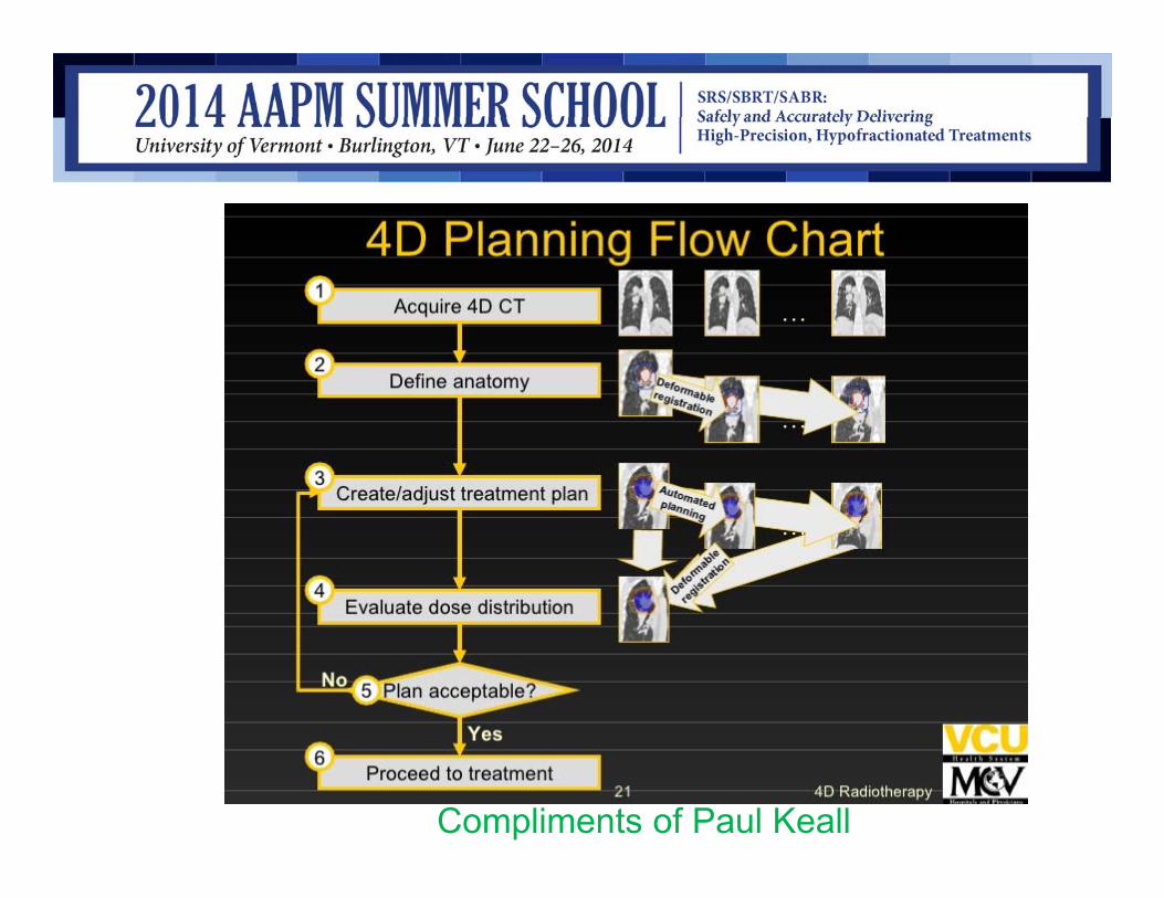
Compliments of Paul Keall

4D treatment planning in the clinic
manual vs. automated contouring results for a single patient, axial, sagittal and coronal views from Pinnacle 7.7. Red contours are for the inhale phase. Colorwash contours are for the manually drawn exhale phase . Auto contours from inhale to exhale are: black (GTV), yellow (cord, heart), pink (esophagus), white (lungs).
K. Wijesooriya et al. Med.Phys. 35, 1251 (2008)
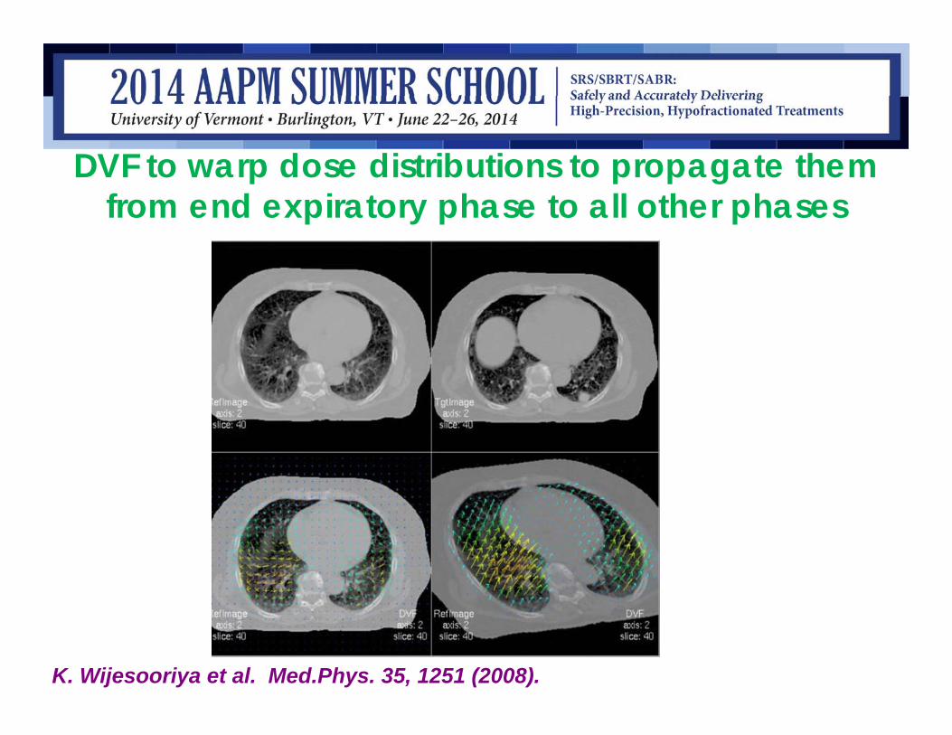
DVF to warp dose distributions to propagate them from end expiratory phase to all other phases
K. Wijesooriya et al. Med.Phys. 35, 1251 (2008).

Deformable Image Registration

4D Radiotherapy is still clinically prohibitive
• Enormous requirements on:– Personnel– Computational resources– Time resources
• New class of uncertainties• Calculated dose is good only for a given
respiratory pattern –respiratory motion unpredictable
• Clinical benefit is still unknown

Some examples of limitations…

Simplified Approach to 4D Treatment Planning
• 4DCT acquisition• Accurate tumor volume definition that
encompasses all tumor locations – motion envelope
• A 3D plan performed on the ITV + margins • On an appropriate reference dataset

Philips Multi-slice CT Scanners with RPMTM
Respiratory Gating
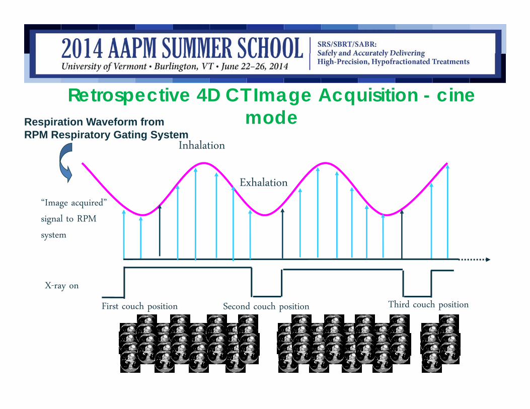
Retrospective 4D CT Image Acquisition - cine modeRespiration Waveform from
RPM Respiratory Gating System
X-ray on
Exhalation
Inhalation
First couch position Second couch position Third couch position
“Image acquired”
signal to RPM
system

4D CT Image Definitions
Helical CT: Helical CT without 4D CT. Snap shot of the anatomy.
MIP (Maximum Intensity Projection image) : Reflect the highest data (hyper-dense) value encountered along the viewing ray for each pixel of volumetric data, giving rise to a full intensity display of the brightest object along each ray on the projection image
So if you are interested in identifying high contrast objects (lung tumor, stents etc..) better to have a MIP

4D CT Image Definitions
MinIP (Minimum Intensity Projection image):projections reflect the lowest data (hypo-dense) value encountered along the viewing ray for each pixel of volumetric data.
So if you are interested in identifying low contrast objects (liver, pancreas etc..) better to have a MinIP

4D CT Image Definitions
Helical MIP MinIP

4DCT imaging studies: References
Nakamura M, Narita Y, Sawada A, et al. Impact of motion velocityon four-dimensional target volumes: A phantom study.Med Phys 2009;36:1610–1617.Abdelnour AF, Nehmeh SA, Pan T, et al. Phase and amplitudebinning for 4D-CT imaging. Phys Med Biol 2007;52:3515–3529.Biederer J, Dinkel J, Remmert G, et al. 4D-imaging of the lung:Reproducibility of lesion size and displacement on helical CT, MRI, and cone beam CT in a ventilated ex vivo system. Int J Radiat Oncol Biol Phys 2009;73:919–926.

Sources of Error in 4DCT
Irregular patient breathing – regular and reproducible breathing by coachingCT image reconstruction algorithmResorting of reconstructed CT images with respiratory signal (phase/amplitude or combination of two)
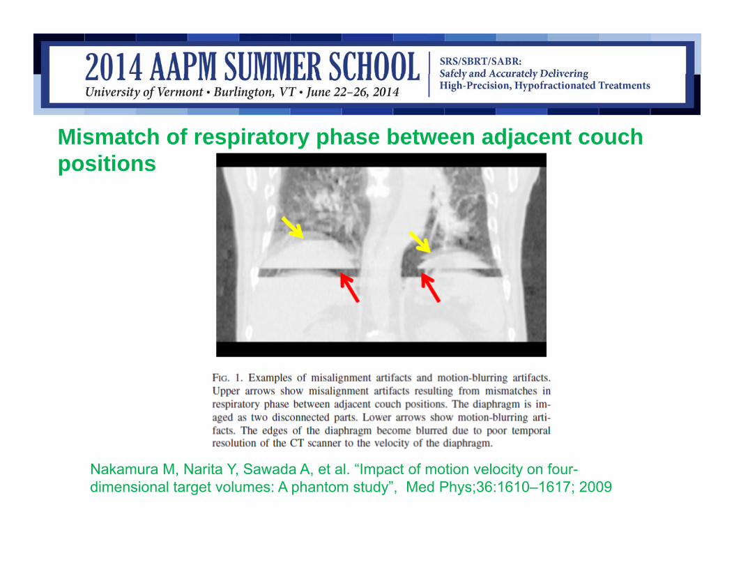
Nakamura M, Narita Y, Sawada A, et al. “Impact of motion velocity on four-dimensional target volumes: A phantom study”, Med Phys;36:1610–1617; 2009
Mismatch of respiratory phase between adjacent couch positions

Amplitude binning is better than phase binning
Abdelnour AF, Nehmeh SA, Pan T, et al. Phase and amplitude binning for 4D-CT imaging. Phys Med Biol 2007;52:3515– 3529.
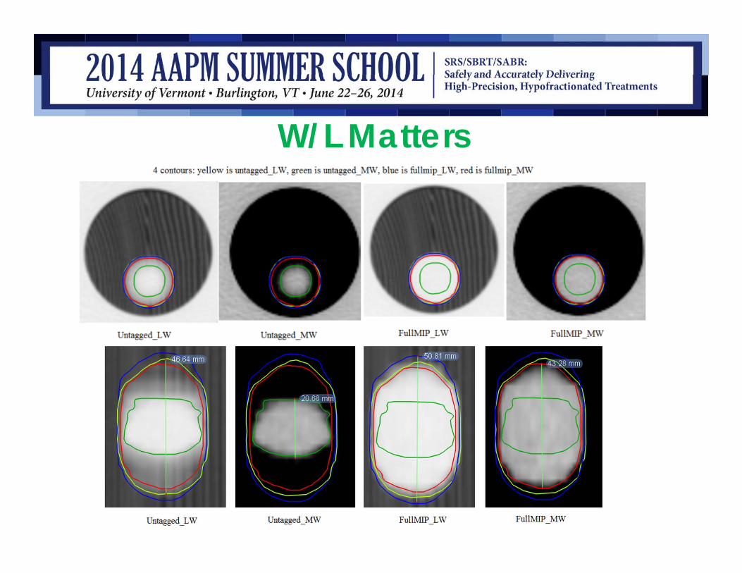
W/L Matters
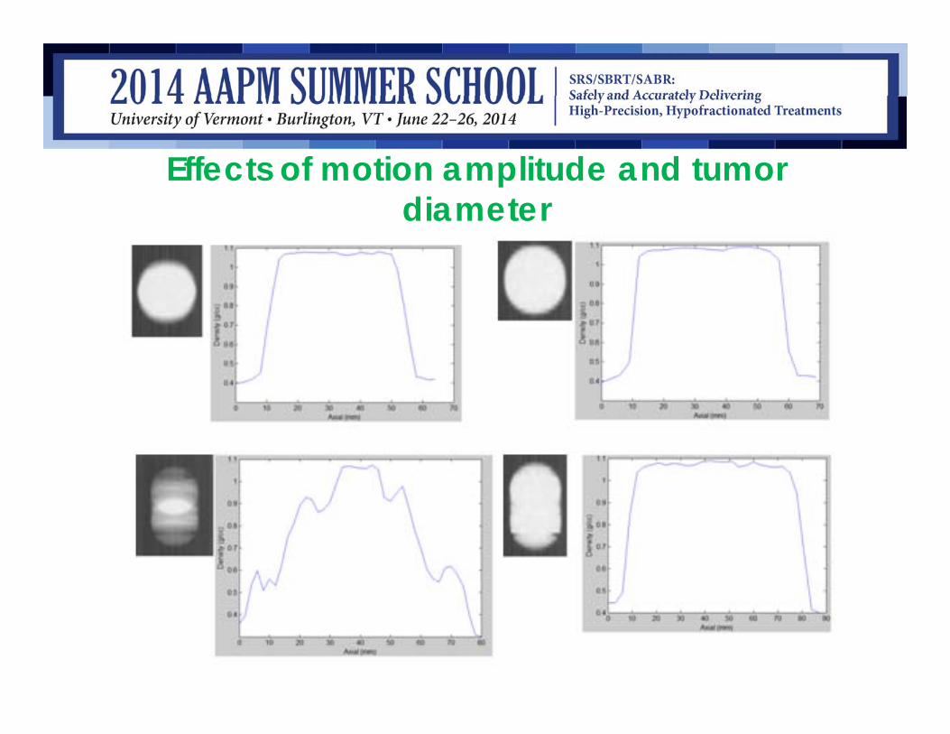
Effects of motion amplitude and tumor diameter

Very small tumors 5cc or less, with large motion amplitudes >1.5cm, due to sampling resolution will show discrete volumes even in FULL_MIP in mediastinum window.
Effects of motion amplitude and tumor diameter

Maximum intensity projection of a highly mobile tumor
Underberg RWM et al IJROBP 2005; 63:253-260

MIPs can be problematic• Drawback for target
delineation: where background and tumor have similar HU, tumor is not as clearly defined
• Example: Caudal extent of ITV may not be correct due to overlap with diaphragm
• Review individual phases
• For this case, send additional scans, e.g. max inhale and max exhale scans to help MD assess tumor motion
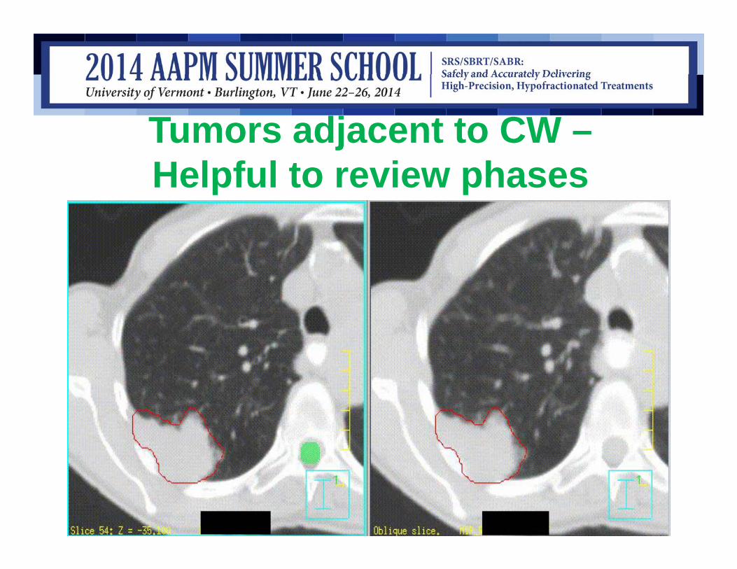
Tumors adjacent to CW –Helpful to review phases

Tumor adjacent to diaphragm
Underberg RWM et al IJROBP 2005; 63:253-260
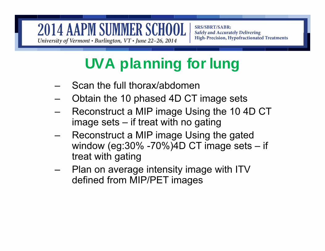
UVA planning for lung– Scan the full thorax/abdomen– Obtain the 10 phased 4D CT image sets– Reconstruct a MIP image Using the 10 4D CT
image sets – if treat with no gating – Reconstruct a MIP image Using the gated
window (eg:30% -70%)4D CT image sets – if treat with gating
– Plan on average intensity image with ITV defined from MIP/PET images

FFF VMAT for lung SBRT
Left – FFF; Right –FF. Notice the better conformity of the 50% isodose (green) line in FFF beams in all three dimensions.

FFF VMAT for lung SBRT
.
FFF beams(in squares) and FF beams (in triangles). PTV – red, 50% prescription isodose – pink, dose distribution beyond 2cm from PTV – green, cord – orange, esophagus – khaki, and total lung –GTV –yellow. Notice that in all cases, FFF beams give a lower out of field dose to different extent when both plans are normalized to cover 95% of PTV to receive the prescription dose
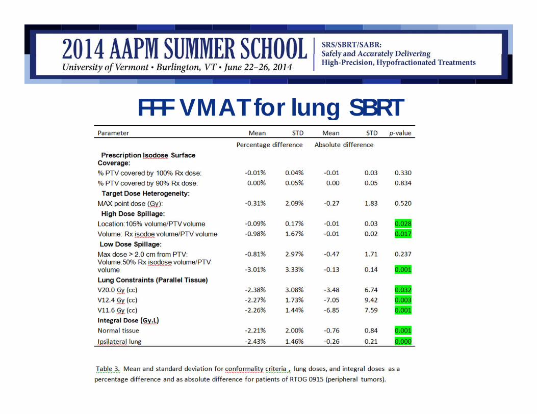
FFF VMAT for lung SBRT
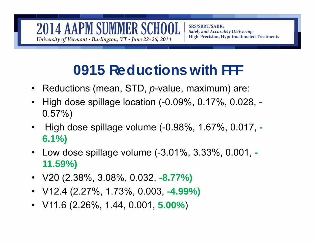
0915 Reductions with FFF• Reductions (mean, STD, p-value, maximum) are: • High dose spillage location (-0.09%, 0.17%, 0.028, -
0.57%)• High dose spillage volume (-0.98%, 1.67%, 0.017, -
6.1%) • Low dose spillage volume (-3.01%, 3.33%, 0.001, -
11.59%)• V20 (2.38%, 3.08%, 0.032, -8.77%)• V12.4 (2.27%, 1.73%, 0.003, -4.99%)• V11.6 (2.26%, 1.44, 0.001, 5.00%)

FFF VMAT for lung SBRT

0813 Reductions with FFF
• Reductions (mean, STD, p-value, maximum) are:
• Low dose spillage volume (-3.27%, 3.87%, 0.026, -11.23%)
• V20 (3.63%, 2.97%, 0.004, 9.88%)• V13.5 (4.47%, 4.48%, 0.04, 12.77%)• V12.5 (4.29, 4.51, 0.04, 11.75%).
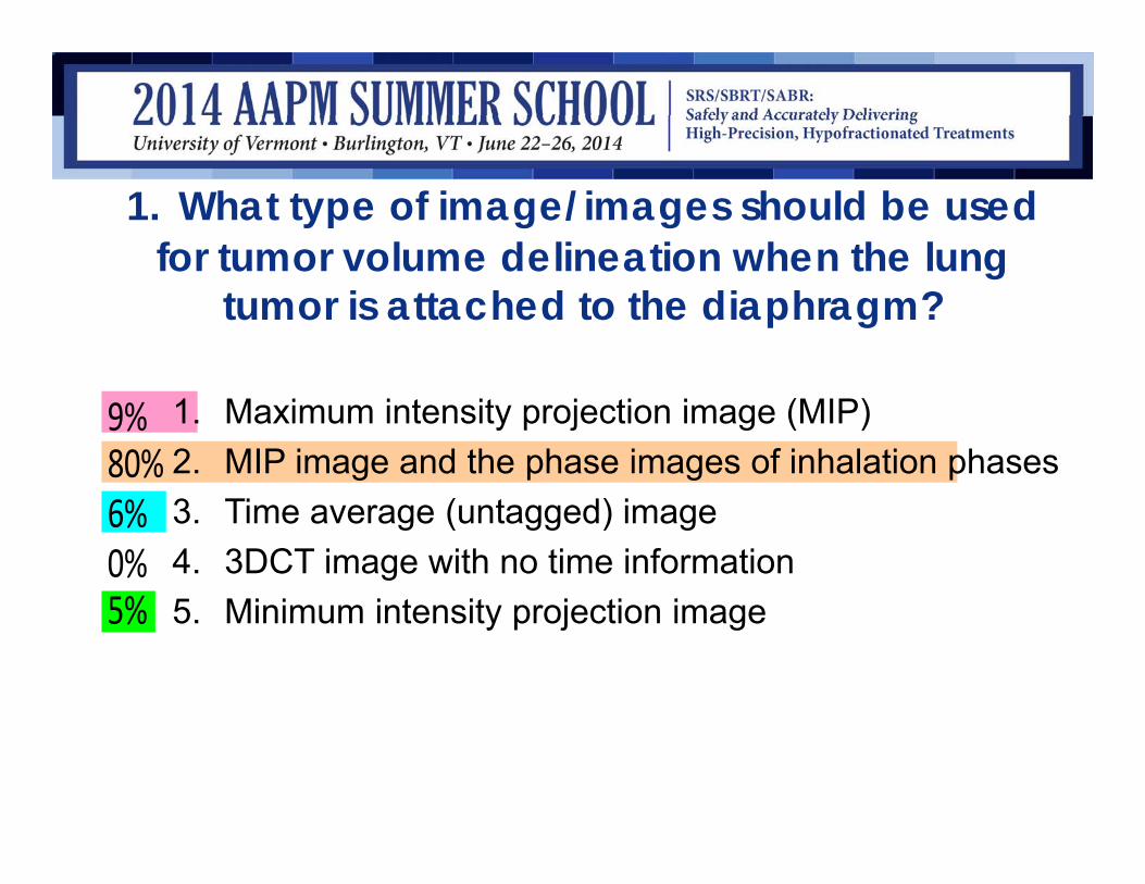
1. What type of image/images should be used for tumor volume delineation when the lung
tumor is attached to the diaphragm?
5%0%6%80%9% 1. Maximum intensity projection image (MIP)
2. MIP image and the phase images of inhalation phases3. Time average (untagged) image4. 3DCT image with no time information5. Minimum intensity projection image

• Answer: 2• References: Underberg RWM et al IJROBP
2005; 63:253-260
What dataset should be chosen for planning?
• Dose computation should be close to cumulative 4D dose computed using all datasets– Rosu M, Balter JM, Chetty IJ, Kessler ML, McShan DL, Balter P, et al.
How extensive of a 4D dataset is needed to estimate cumulative dosedistribution plan evaluation metrics in conformal lung therapy? MedPhys 2007;34:233–45.
• Anatomy of this image set should correlate well with the tumor image of pre-treatment image (CBCT/MVCT)
• Average intensity image should be used for planning

2. What is the optimum dataset for dose calculation of a lung Tx?
0%88%2%10%0%1. 3DCT image which carries a snap shot of the tumor position
2. Maximum intensity projection image (MIP)3. Minimum intensity projection image (Minip)4. Time average (untagged) image5. CBCT image

• Answer: 4• References: • • MA Admiraal, D.Schuring, CW Hurkmans “Dose calculations
accounting for breathing motion in stereotactic lung radiotherapy based on 4D-CT and the internal target volume”, Radiotherapy and oncology 86 (2008) 55-60
• • Yuan Tian, Zhiheng Wang, Hong Ge, Tian Zhang, Jing Cai, Christopher Kelsey, David Yoo, Fang-Fang Yin. “DosimetricComparison of Treatment Plans Based on Free Breathing, Maximum and Average Intensity Projection CTs for Lung Cancer SBRT.” Med Phys 39:2754-2760 (2012)

3. Which of the following is accepted as a lung SBRT planning technique?
5%
92%
1%
0%
2% 1. CBCT image is used for ITV definition and dose calculation
2. 3D CT image used for ITV definition
3. 3DCT image used for dose calculation
4. ITV is defined by the MIP image and the time averaged image used for dose calculation
5. ITV is defined by the MINiP image and the time averaged image used for dose calculation

• Answer: 4• References: • • Guckenberger M, Wilbert J, Krieger T, et al. Four-dimensional
treatment planning for stereotactic body radiotherapy. Int J RadiatOncol Biol Phys 2007;69:276–85.
• • MA Admiraal, D.Schuring, CW Hurkmans “Dose calculations accounting for breathing motion in stereotactic lung radiotherapy based on 4D-CT and the internal target volume”, Radiotherapy and oncology 86 (2008) 55-60
• • Kaus MR, Brock KK, Pekar V, et al. Assessment of a model based deformable image registration approach for radiation therapy planning. Int J Radiat Oncol Biol Phys 2007;68:572–80.
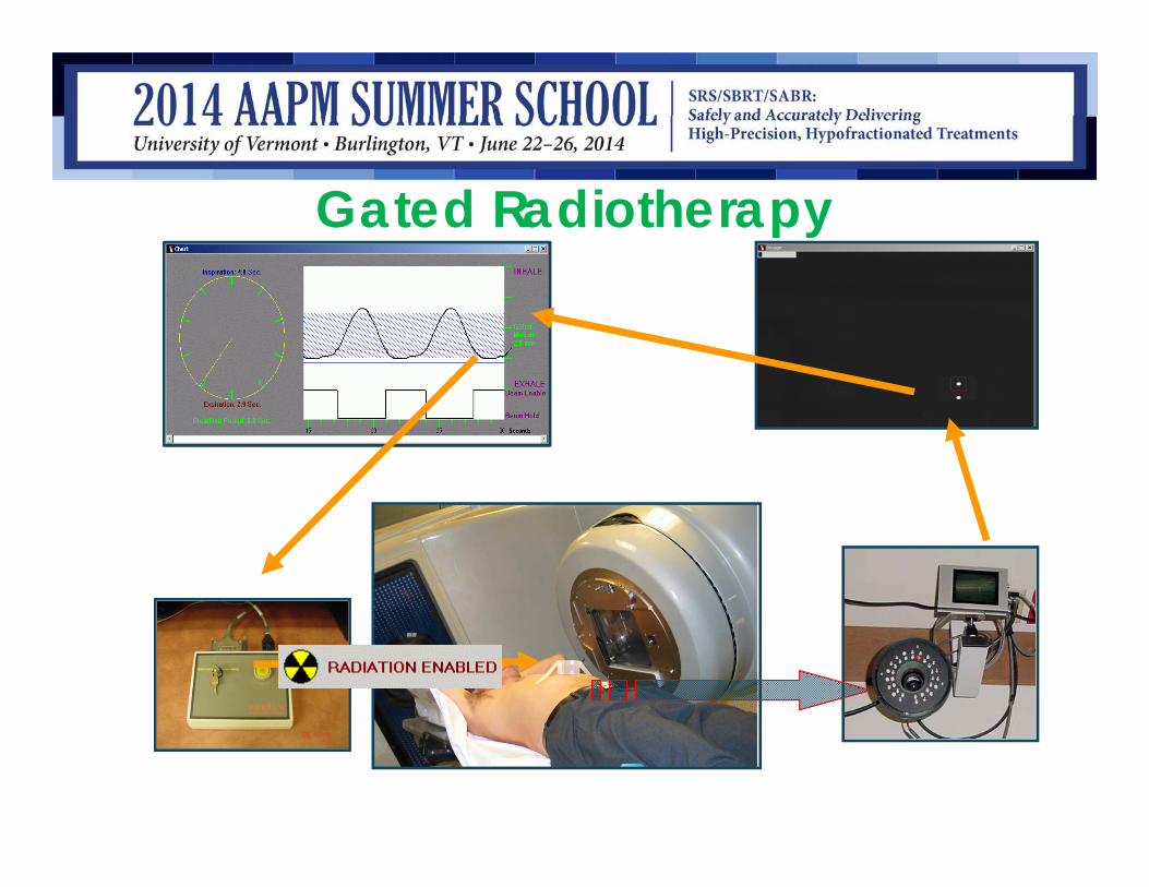
Gated Radiotherapy

To Ensure an Accurate Externally Gated Treatment, five QA Steps
1. During Simulation, the reference home position should be accurately measured (4DCT)
2. During Tx planning, patient and tumor geometry corresponding to the gating window should be used

To ensure an Accurate Externally Gated Treatment, five QA steps
3. During patient setup tumor home position at this fractionation should be matched to the reference home position – image guidance (x-ray, Ultrasound, implanted E.M transponders), lung: tumor or diaphragm, liver: implanted fiducial markers

To ensure an Accurate Externally Gated Treatment, five QA steps
3. During patient setup tumor home position at this fractionation should be matched to the reference home position – image guidance (x-ray, Ultrasound, implanted E.M transponders), lung: tumor or diaphragm, liver: implanted fiducial markers – to avoid inter-fraction variation
To Ensure an Accurate Externally Gated Treatment, Five QA Steps Continued…
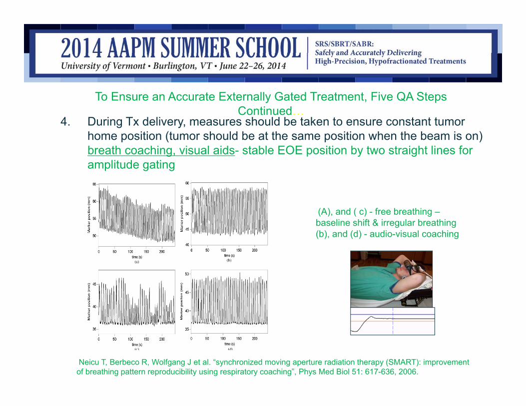
4. During Tx delivery, measures should be taken to ensure constant tumor home position (tumor should be at the same position when the beam is on) breath coaching, visual aids- stable EOE position by two straight lines for amplitude gating
Neicu T, Berbeco R, Wolfgang J et al. “synchronized moving aperture radiation therapy (SMART): improvement of breathing pattern reproducibility using respiratory coaching”, Phys Med Biol 51: 617-636, 2006.
(A), and ( c) - free breathing –baseline shift & irregular breathing(b), and (d) - audio-visual coaching

To Ensure an Accurate Externally Gated Treatment, Five QA Steps Continued…
5. During Tx delivery, tumor positions corresponding to the gating window should be measured and compared with the reference home position, either on or offline. EPID in cine mode for small patients and non-IMRTs (Ref: berbeco RI, Neicu T, Rietzel E et al. “A technique for respiratory-gated radiotherapy treatment verification with an EPID in cine mode”, Phys Med Biol 50:3669-3679 2005), OBI KV images for others

How to ensure treatment accuracy when internal target position is predicted using external surrogates
Surrogates used to generate gating signals1. External surrogates: markers placed on the patients outside surface
1. Varian RPM system2. Active breathing control using spirometery3. Siemens Anzai pressure belt: bellows system4. Medspira respiratory monitoring bellows system
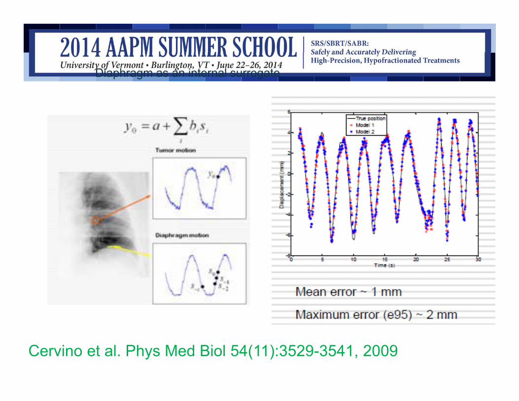
Diaphragm as an internal surrogate
Cervino et al. Phys Med Biol 54(11):3529-3541, 2009

Keall PJ, Mageras GS, Balter JM, etal. The management of respiratory motion in radiation oncology report of AAPM TG 76, Med Phys; 33:3874-3900 2006Jiang S., Wolfgang J, Mageras GS “ Quality assurance challenges for motion-adaptive radiation therapy: gating, breath holding, and four-dimensional computed tomography”, IJROBP 71(1):S103-S107 2008
•Typical QA measures•Initial testing of equipment and clinical procedures: CT scanner, fluoroscope, linac, gating…..•Frequent QA examination during early stage on implementation
Three Phases of 4D QA
4DCT scan QA
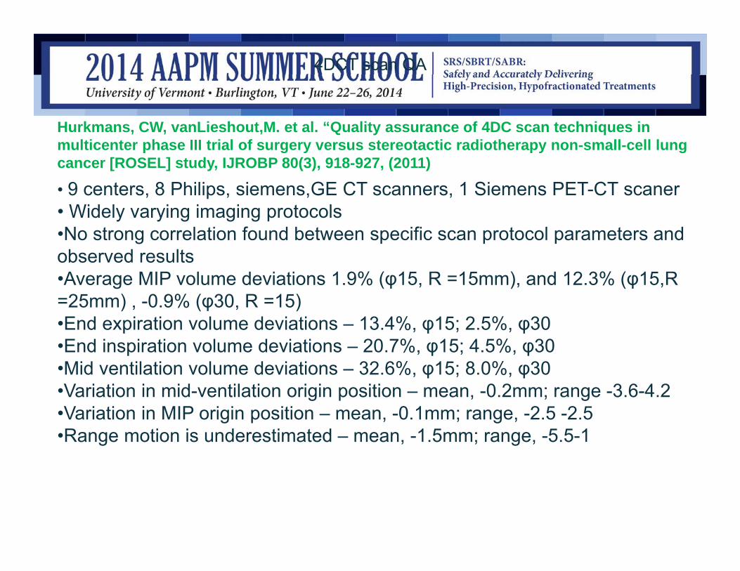
Hurkmans, CW, vanLieshout,M. et al. “Quality assurance of 4DC scan techniques in multicenter phase III trial of surgery versus stereotactic radiotherapy non-small-cell lung cancer [ROSEL] study, IJROBP 80(3), 918-927, (2011)
• 9 centers, 8 Philips, siemens,GE CT scanners, 1 Siemens PET-CT scaner• Widely varying imaging protocols•No strong correlation found between specific scan protocol parameters and observed results•Average MIP volume deviations 1.9% (φ15, R =15mm), and 12.3% (φ15,R =25mm) , -0.9% (φ30, R =15)•End expiration volume deviations – 13.4%, φ15; 2.5%, φ30•End inspiration volume deviations – 20.7%, φ15; 4.5%, φ30•Mid ventilation volume deviations – 32.6%, φ15; 8.0%, φ30•Variation in mid-ventilation origin position – mean, -0.2mm; range -3.6-4.2•Variation in MIP origin position – mean, -0.1mm; range, -2.5 -2.5•Range motion is underestimated – mean, -1.5mm; range, -5.5-1

Future of 4D QA
• Extend the QA to measure/evaluate 4D dose delivery:– Estimate from 4D planning– Perform phantom measurements – Evaluate actual 4D dose delivery

Some publications on interplay
Yu Cx, Jaffray DA, Wong JW, “Effects of intra-fraction motion on the delivery of dynamic intensity modulation”, Phys Med Biol. 1998, 43(1):91-104.Bortfeld T., “Effects of intra-fraction motion on IMRT dose delivery: statistical analysis and simulation”, Phys Med Biol 47: 2203-2220, 2002.Engelsman M, Damen EM, De Jaeger K, van Ingen KM, Mijnheer, BJ, “ The effects of breathing and set-up errors on the cumulative dose to a lung tumor”, Radiotherapy Oncol., 60(1):95-105, 2001.Chui CS, Yorke, E, Hong L, “The effects of intra-fraction organ motion on the delivery of intensity-modulated field with a multileaf collimator”, Med Phys 30(7): 1736-46 2003.Duan J, Shen S., Fiveash JB, Popple RA, Brezovich IA, “Dosimetric and radiobiological impact of dose fractionation on respiratory motion induced IMRT delivery errors: a volumetric dose measurement study”, Med Phys 34(3):923-34, 2007Seco J, Sharp GC, Turcotte J, Gierga D, Bortfeld T, paganetti H. “ Effects of organ motion on IMRT traetments with segments of few monitor units”, Med Phys. 37 5850 2010.
Summary|Conclusion1. Motion envelope should be measured prior to ITV definition2. Particular care should be given to tumors attached to chest
wall/diaphragm3. Planning CT should be a time averaged CT image4. Gated image reference position should be verified prior to Tx5. End to end QA program should be established prior to going
clinical

AcknowledgementsThanks to University of Virginia Dept. of Radiation Oncology!