Ilizarov Frame Principles - SIGN Fracture Care International · Fracture Healing . Stability of...
96
SIGN 2015 Richard Gellman, MD Portland, OR
Transcript of Ilizarov Frame Principles - SIGN Fracture Care International · Fracture Healing . Stability of...

SIGN 2015
Richard Gellman, MD Portland, OR

Objectives
Fracture healing biology Osteotomy techniques Ring fixator techniques &
biomechanics

Fracture Healing
Endochondral bone repair •callus, secondary bone healing •interfragmentary motion
Primary bone repair •direct contact repair •absolute stability / no fracture gap
4 general types of bone repair
The route of repair is dependent on the mechanical environment
Gap repair •direct repair •stable fixation / small gap
Distraction osteogenesis •callotasis •slow distraction of fracture gap

Mode of healing and mechanics

Fracture Healing Stability of fracture determines the morphology of healing
• Functional reduction
• Flexible fixation
• IFM = 0.2 – 1 mm 3; > 10 mm 4
• Dynamization 4
[3] Kenwright, CORR, ’98; [4] Augat, JOT 2008 [1] Hayda, CORR, ’98; [2] Perren, CORR ‘79
• Perfect Reduction
• Absolute Stabilization 1,2
• IFM <0.15 mm
• Interfragmentary Compression
Callus Healing Primary / Gap Healing

Mechanical environment and healing
No Callus
Rigid Fixation Non-rigid Fixation
Primary healing
Secondary healing
Callus
Nonunion
Excessive motion
Hypertrophic callus
Nirula, World J Surgery, 2009

Secondary Healing
Inflammatory Stage
• Hematoma is formed and inflammation occurs (potential disruption of healing by NSAIDs)
• Hematoma is a source of signaling molecules critical to
the healing cascade
• Necrosis of the bone ends

Secondary Healing
Soft callus formation • Cartilage is formed in the fracture site
• Bone begins to form directly, mostly along the periosteum
• Vascular ingrowth begins to occur
• Disruption of blood supply (e.g. smoking) at this stage delays
healing
• Micromotion at the fracture site is vital to soft callus formation

Secondary Healing
Hard callus formation • Cartilage deposited at the fracture site begins to
calcify
• Calcification continues until the bone ends are united
• Woven bone is deposited at the fracture site
• Blood supply continues to improve
Grabber et al. J Trauma, 1985

Secondary Healing
Remodeling • Hard callus (both the external bridging callus and the medullary callus) is remodeled into mature bone
Grabber et al. J Trauma, 1985

Flexible plating with motion-lock screws=abundant callus formation

What is the ideal choice?
Patient: age, health, vascular supply Surgical environment: sterility,
radiography Resources: plates, nails, external
fixation The Times They are a-Changin’
Bob Dylan 1964

Osteotomy Techniques
Percutaneous Preserve periosteal blood supply Technique varies with location
Multipe Drill Hole: diaphyseal, dense bone Gigli: metaphyseal, soft bone
Performed after frame application Latency period: 7-14 days

Multiple Drill Hole osteotomy
1 cm anterior longitudinal incision Careful periosteal elevation 4.8 mm drill hole: one anterior hole-
several posterior holes 10 mm sharp osteotome Complete with 90 deg turn of osteotome Requires rod/strut removal to complete

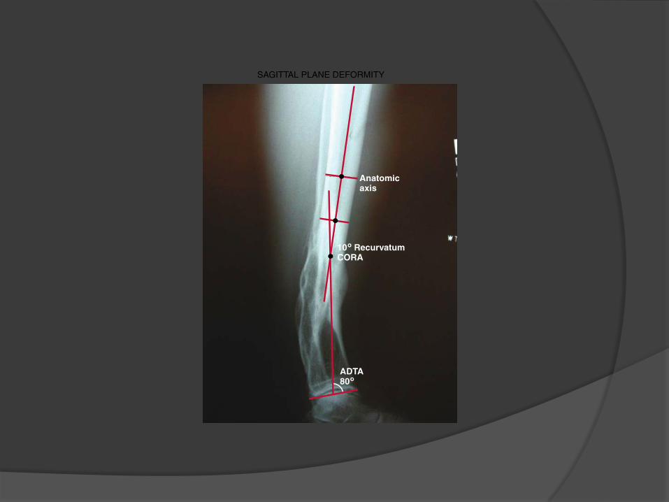


Surgical Treatment

Gigli saw osteotomy
2 transverse incisions, 1 cm each Careful periosteal elevation Pass suture- done prior to frame app Saw passed with suture May include fibula- distal supra-
malleolar Rods/struts remain intact Compress 1-2 mm

Proximal Tibia Gigli


Distal Tibia Gigli


Low distal tibia Gigli


41 yo oral surgeon

10 months later

1.5 year follow-up

Bilat tibia, femur, foot, >350 lb


Tib-Calc Fusion, Tibia Lengthening


Fibula Osteotomy
May use small sagittal saw Multiple drill hole technique with 2.0 drill
or 1.8 wire Rarely remove section Done prior to frame application

Dome Osteotomy
Open procedure Acute correction with internal fixation Frontal or sagittal plane deformity <12
deg, with minimal translation Most common in distal tibia or distal
femur

Equal Tibia and Fibula
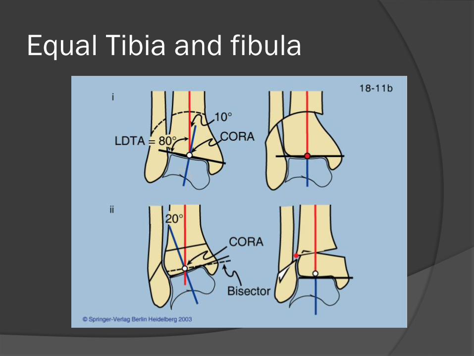
Equal Tibia and fibula


Follow-up

What’s a stable ring fixator?
Pain-free Balanced Weight-bearing Optimal environment for healing

Ring fixation mechanics Cyclic axial micromotion promotes bone healing,
only if it’s not excessive or absent (about 1 mm) Translational shear inhibits bone healing Bending less clear (inhibitive) Goal- low axial stiffness, high bending,
translational and torsional stiffness (Ilizarov)


What creates a strong frame?
The combination of the frame and the fixation
“Frame stability” rings or ring blocks wires and half pins connections of wires and half-pins to the
rings connections b/t rings (rods or TSF struts)
Ideal Ring Fixator Maximum rigidity to prevent shearing motion at
fracture site Controllable axial stiffness to optimize IFM
throughout healing Minimal soft tissue violation Maintenance of strength throughout treatment Watson, Mathias, Maffulli: 2000 U of Aberdeen, Scotland

Rings
Ring sizing is very important (#1) Gasser (1990) , Bronson (1998): Most
important factor in overall frame stiffness 2 cm soft tissue clearance (anticipate
swelling) TSF allows for multiple ring sizes Typically, use the smallest possible
(exceptions)


Rings
Bone position: central optimum, but eccentric OK
Orthogonal to limb segment: helpful for connections
Long unsupported distances- consider a dummy ring
Partial rings: greater plastic deformation with wire tensioning and less stiff than complete rings (Cross et al , Am J Vet Res, 2004)

Enclose the foot ring

Single ring # of wires, half pins
per ring Metaphysis – 4 to 5
fixation points, varies from 1-3 wires, 2-3 half pins

Ring Block concept
The portion of a frame attached to a bone/limb segment
Often 2 rings connected by 4 threaded rods
To optimize stability: min of 4 points of fixation (2-3 per ring), fix the near and far ends of segment
Short metaphyseal segments: one ring with 3-5 fixation points

Ring Blocks Strength increases
rings are closer to the bone (2 cm clearance)
# of rings # of threaded rods
between rings

Ring Blocks
More stability nonunions, unstable fracture patterns, fusions, obesity, neuropathy
Less stability lengthening Medium transport, stable fracture

Connecting rings to bone

Wires Traditional Ilizarov fixation 1.8 mm (1.5mm in small applications) Provides stable fixation in small bone segments,
osteopenia, neuropathic, metaphyseal, feet Useful for achieving orthogonal ring application:
reference wire for reference ring

Reference ring - wire

Wires
To increase frame stability: Increase wire diameter, number, tension,
crossing angle (ideal 90, aim for 60) Opposing olive wires (rule of thumbs for
deformity correction) Olive wires can be used to pull or move
bone segments Drop wires


Drop Wires

Increases with wire tension Metaphyseal bone
90-110 kg Diaphyseal bone 110-
130 kg Drop wires/metatarsal
50-90 kg

Wire Tension Loss of tension occurs:
Rapid reduction in wire tension (25+%-75%) Clamping wire squeezes it (toothpaste out of
tube)plastic deformation. More with cannulated Wire slippage thru bolts. Most with Russian. Best tighten
to 14Nm (bolt failure near 20). Most likely cause. Strut torque wrench=5.6Nm
Cyclic axial micromotion is preserved due to wire recoil with loading
Re-tensioning wires not supported experimentally

Wire Insertion Technique Bicortical Avoid dense bone Use saline sponge to
cool No paralytics No tourniquet Tap or oscillate wire
thru far tissues Joints at end of range


Half Pins
Use began with Ilizarov methods due to wire issues: pain, infection, soft tissue issues, etc
Typically used in diaphyseal bone Calhoun et al , 1992: Rigidity of half-pins for the
Ilizarov external fixator. Cadaver one ring study Rigidity: 1w+3p>3p (5mm)>1w+2p(5mm)

Half Pins
To increase stability with half pins: Increase diameter (bending and torsion = r4) – core
diameter if threads outside of bone Sizes range from 4 to 6 mm (< 1/3 bone diameter) Increase number Crossing angle/divergence Pin Spread (near/far)

Smallest diameter outside of bone determines stiffness. Therefore, if pin threads out of bone, bending stiffness α core diameter.

Half Pin frame connections
Rancho cubes Half pin fixation
bolts Angled clamps Mix

Half Pin Insertion Technique Irrigation during
drilling Drilling technique Always bicortical Avoid sclerotic bone No tourniquet

Half Pin Insertion Technique
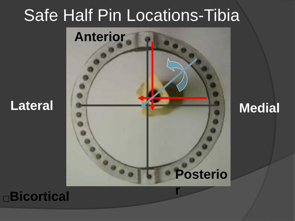
Safe Half Pin Locations-Tibia
Bicortical
Lateral Medial
Anterior
Posterior

Steerage Pins
Lowenberg et al, 2008, CORR: Correlation of shear to compression for progressive fracture obliquity Synthetic tibia fracture model to assess fracture line
migration with multiple frame configurations Only parallel oblique half pins limit motion with loading
from 40-60 degrees fracture obliquity= shear becomes compression
All are good below 30 degrees


Ring Block Fixation: Wires vs. Pins
Lenarz et al, 2008, CORR: Circular External Fixation Frames with Divergent Half Pins Compared 3 four ring constructs sawbone
model Two 90° wires/ring (8 wires); two 90° 5 mm
pins/ring (8 pins); three 6mm pins 60 ° divergent per block(6 pins)
Rigidity: wire< 5mm pins = 6 mm pins Bottom Line: consider divergent half pins in tibia


SUMMARY: Fixation Basics
Start with the “Rule of two’s” 2 cm soft tissue clearance 2 rings/segment (ring block) 2 points fixation/ring 2x2 connecting rods (except tsf struts)
Recent mechanical studies Three divergent 6mm half pins per bone segment Steerage pins for oblique fractures
Preoperatively plan using mechanical principles