II Blade/HLQ&A Center Assy UT HTS #69500/69525/69525-1
16
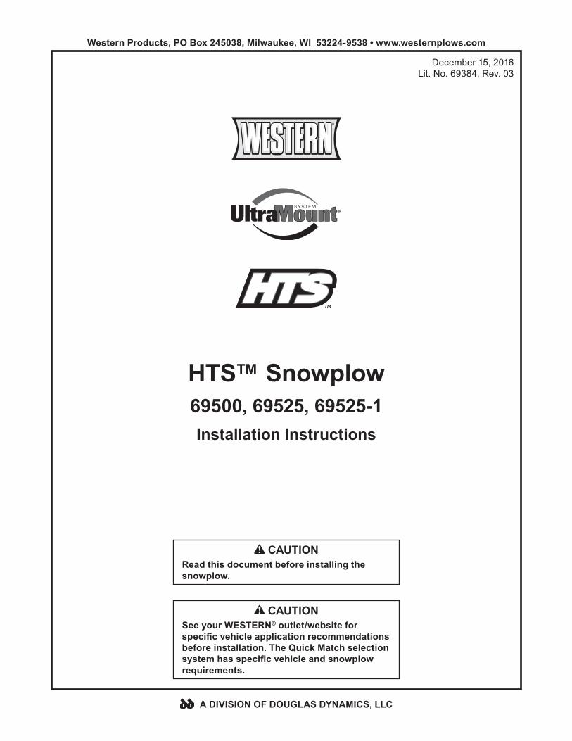
HTS™ Snowplow 69500, 69525, 69525-1 Installation Instructions Western Products, PO Box 245038, Milwaukee, WI 53224-9538 • www.westernplows.com December 15, 2016 Lit. No. 69384, Rev. 03 A DIVISION OF DOUGLAS DYNAMICS, LLC CAUTION Read this document before installing the snowplow. CAUTION See your WESTERN ® outlet/website for specific vehicle application recommendations before installation. The Quick Match selection system has specific vehicle and snowplow requirements.
Transcript of II Blade/HLQ&A Center Assy UT HTS #69500/69525/69525-1
HTS™ Snowplow69500, 69525, 69525-1Installation Instructions
Western Products, PO Box 245038, Milwaukee, WI 53224-9538 • www.westernplows.com
December 15, 2016Lit. No. 69384, Rev. 03
A DIVISION OF DOUGLAS DYNAMICS, LLC
CAUTIONRead this document before installing the snowplow.
CAUTIONSee your WESTERN® outlet/website for specific vehicle application recommendations before installation. The Quick Match selection system has specific vehicle and snowplow requirements.

Lit. No. 69384, Rev. 03 3 December 15, 2016
SAFETY
SAFETY DEFINITIONS
NOTE: Indicates a situation or action that can lead to damage to your snowplow and vehicle or other property. Other useful information can also be described.
WARNINGIndicates a potentially hazardous situation that, if not avoided, could result in death or serious personal injury.
CAUTIONIndicates a potentially hazardous situation that, if not avoided, may result in minor or moderate injury. It may also be used to alert against unsafe practices.
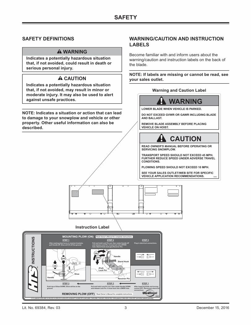
Instruction Label
Warning and Caution Label
LOWER BLADE WHEN VEHICLE IS PARKED.
DO NOT EXCEED GVWR OR GAWR INCLUDING BLADE AND BALLAST.
REMOVE BLADE ASSEMBLY BEFORE PLACING VEHICLE ON HOIST.
READ OWNER'S MANUAL BEFORE OPERATING OR SERVICING SNOWPLOW.
TRANSPORT SPEED SHOULD NOT EXCEED 45 MPH. FURTHER REDUCE SPEED UNDER ADVERSE TRAVEL CONDITIONS.
PLOWING SPEED SHOULD NOT EXCEED 10 MPH.
SEE YOUR SALES OUTLET/WEB SITE FOR SPECIFIC VEHICLE APPLICATION RECOMMENDATIONS. 59900
WARNING
CAUTION
WARNING/CAUTION AND INSTRUCTION LABELS
Become familiar with and inform users about the warning/caution and instruction labels on the back of the blade.
NOTE: If labels are missing or cannot be read, see your sales outlet.

Lit. No. 69384, Rev. 03 4 December 15, 2016
SAFETY
HYDRAULIC SAFETY
• Always inspect hydraulic components and hoses before using. Replace any damaged or worn parts immediately.
• If you suspect a hose leak, DO NOT use your hand to locate it. Use a piece of cardboard or wood.
FUSES
The electrical and hydraulic systems contain several blade-style automotive fuses. If a problem should occur and fuse replacement is necessary, the replacement fuse must be of the same type and amperage rating as the original. Installing a fuse with a higher rating can damage the system and could start a fire. Fuse Replacement, including fuse ratings and locations, is located in the Maintenance Section of the Owner's Manual.
PERSONAL SAFETY
• Remove ignition key and put the vehicle in park or in gear to prevent others from starting the vehicle during installation or service.
• Wear only snug-fitting clothing while working on your vehicle or snowplow.
• Do not wear jewelry or a necktie, and secure long hair.
• Wear safety goggles to protect your eyes from battery acid, gasoline, dirt and dust.
• Avoid touching hot surfaces such as the engine, radiator, hoses and exhaust pipes.
• Always have a fire extinguisher rated BC handy, for flammable liquids and electrical fires.
WARNINGHydraulic fluid under pressure can cause skin injection injury. If you are injured by hydraulic fluid, get medical attention immediately.
SAFETY PRECAUTIONS
Improper installation and operation could cause personal injury and/or equipment and property damage. Read and understand labels and the Owner's Manual before installing, operating or making adjustments.
WARNINGLower blade when vehicle is parked. Temperature changes could change hydraulic pressure, causing the blade to drop unexpectedly or damaging hydraulic components. Failure to do this could result in serious personal injury.
WARNINGRemove blade assembly before placing vehicle on hoist.
WARNINGThe driver shall keep bystanders clear of the blade when it is being raised, lowered or angled. Do not stand between the vehicle and the blade or within 8 feet of a moving blade. A moving or falling blade could cause personal injury.
WARNINGDo not exceed GVWR or GAWR including blade and ballast. The rating label is found on driver-side vehicle door cornerpost.
WARNINGTo prevent accidental movement of the blade, always turn the control OFF whenever the snowplow is not in use. The power indicator light will turn OFF.
WARNINGKeep hands and feet clear of the blade and A-frame when mounting or removing the snowplow. Moving or falling assemblies could cause personal injury.
CAUTIONRefer to the current Quick Match selection system for minimum vehicle recommendations and ballast requirements.

Lit. No. 69384, Rev. 03 5 December 15, 2016
SAFETY
BATTERY SAFETY
TORQUE CHART
1/4-20 109 1541/4-28 121 1715/16-18 150 2125/16-24 170 2403/8-16 269 3763/8-24 297 4207/16-14 429 6067/16-20
9/16-129/16-185/8-115/8-183/4-103/4-167/8-97/8-14 474 669
644 9091-81-12 704 995
1/2-131/2-20
11.913.724.627.343.6
26.953.393148
49.469.877.9
106.4120.0
8.49.717.419.230.835.049.455.275.385.0
M6 x 1.00
M12 x 1.75
M8 x 1.25
M14 x 2.00
M10 x 1.50M27 x 3.00
M22 x 2.50
M30 x 3.50
M24 x 3.00
M20 x 2.5011.119.538.567107
7.761377811391545
4504285627961117
M33 x 3.50M36 x 4.00
21012701
14681952
325
M16 x 2.00 231167M18 x 2.50 318222
Recommended Fastener Torque Chart
Size SizeTorque (ft-lb)
Grade5
Grade8
Metric Fasteners Class 8.8 and 10.9
These torque values apply to fastenersexcept those noted in the instructions.
Torque (ft-lb)Grade
5Grade
8
Size SizeTorque (ft-lb)
Class8.8
Class10.9
Torque (ft-lb)Class
8.8Class10.9
Inch Fasteners Grade 5 and Grade 8
FIRE AND EXPLOSION
Be careful when using gasoline. Do not use gasoline to clean parts. Store only in approved containers away from sources of heat or flame.
CELL PHONES
A driver's first responsibility is the safe operation of the vehicle. The most important thing you can do to prevent a crash is to avoid distractions and pay attention to the road. Wait until it is safe to operate Mobile Communication Equipment such as cell phones, text messaging devices, pagers or two-way radios.
VENTILATION
CAUTIONBatteries normally produce explosive gases which can cause personal injury. Therefore, do not allow flames, sparks or lit tobacco to come near the battery. When charging or working near a battery, always cover your face and protect your eyes, and also provide ventilation.Batteries contain sulfuric acid which burns skin, eyes and clothing.Disconnect the battery before removing or replacing any electrical components.
CAUTIONRead instructions before assembling. Fasteners should be finger tight until instructed to tighten according to torque chart. Use standard methods and practices when attaching snowplow including proper personal protective safety equipment.
WARNINGVehicle exhaust contains lethal fumes. Breathing these fumes, even in low concentrations, can cause death. Never operate a vehicle in an enclosed area without venting exhaust to the outside.
WARNINGGasoline is highly flammable and gasoline vapor is explosive. Never smoke while working on vehicle. Keep all open flames away from gasoline tank and lines. Wipe up any spilled gasoline immediately.
Lit. No. 69384, Rev. 03 6 December 15, 2016
INSTALLATION INSTRUCTIONS
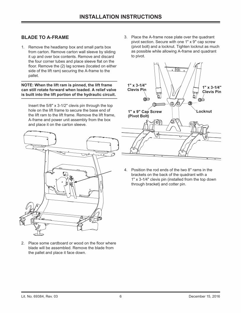
BLADE TO A-FRAME
1. Remove the headlamp box and small parts box from carton. Remove carton wall sleeve by sliding it up and over box contents. Remove and discard the four corner tubes and place sleeve flat on the floor. Remove the (2) lag screws (located on either side of the lift ram) securing the A-frame to the pallet.
NOTE: When the lift ram is pinned, the lift frame can still rotate forward when loaded. A relief valve is built into the lift portion of the hydraulic circuit.
Insert the 5/8" x 3-1/2" clevis pin through the top hole on the lift frame to secure the base end of the lift ram to the lift frame. Remove the lift frame, A-frame and power unit assembly from the box and place it on the carton sleeve.
2. Place some cardboard or wood on the floor where blade will be assembled. Remove the blade from the pallet and place it face down.
3. Place the A-frame nose plate over the quadrant pivot section. Secure with one 1" x 9" cap screw (pivot bolt) and a locknut. Tighten locknut as much as possible while allowing A-frame and quadrant to pivot.
4. Position the rod ends of the two 8" rams in the brackets on the back of the quadrant with a 1" x 3-1/4" clevis pin (installed from the top down through bracket) and cotter pin.
1" x 9" Cap Screw (Pivot Bolt)
Locknut
1" x 3-1/4" Clevis Pin 1" x 3-1/4"
Clevis Pin
Lit. No. 69384, Rev. 03 7 December 15, 2016
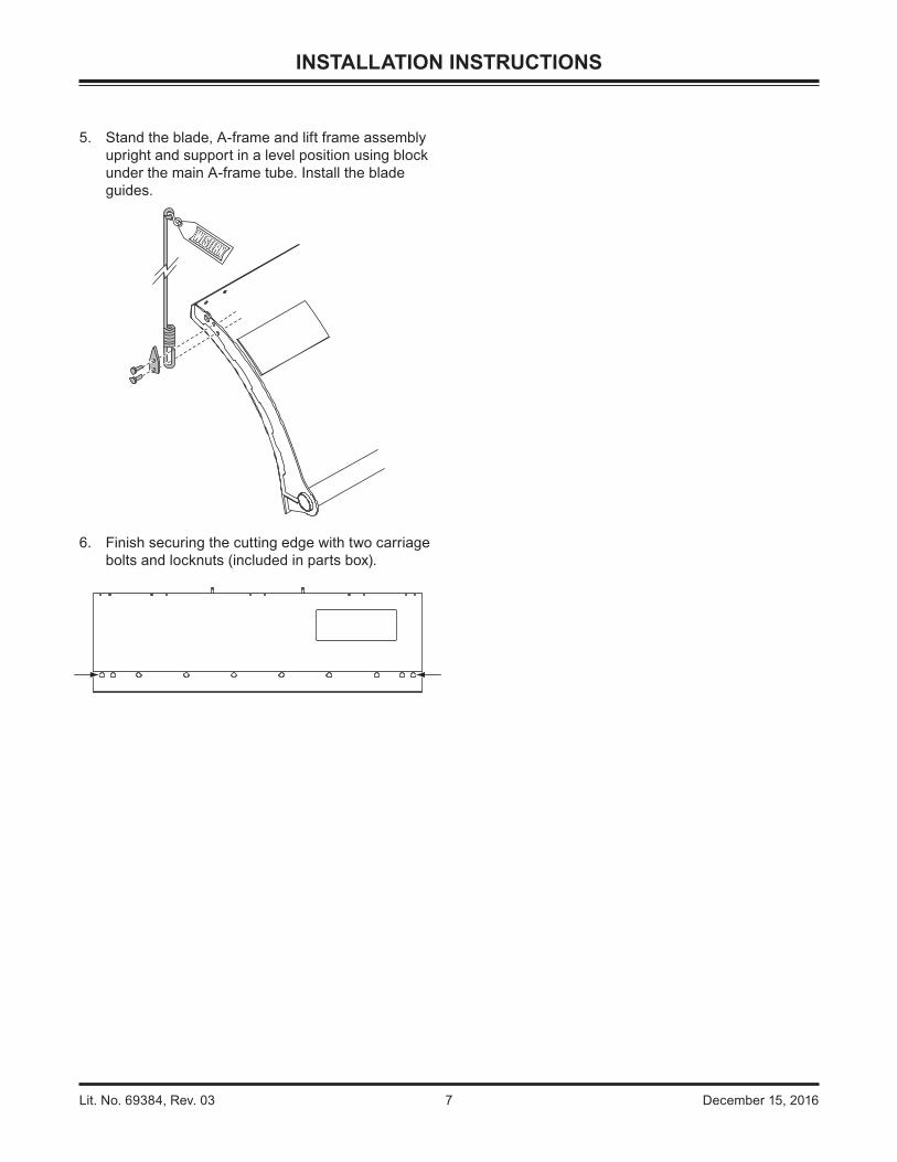
5. Stand the blade, A-frame and lift frame assembly upright and support in a level position using block under the main A-frame tube. Install the blade guides.
6. Finish securing the cutting edge with two carriage bolts and locknuts (included in parts box).
INSTALLATION INSTRUCTIONS
Lit. No. 69384, Rev. 03 8 December 15, 2016
INSTALLATION INSTRUCTIONS
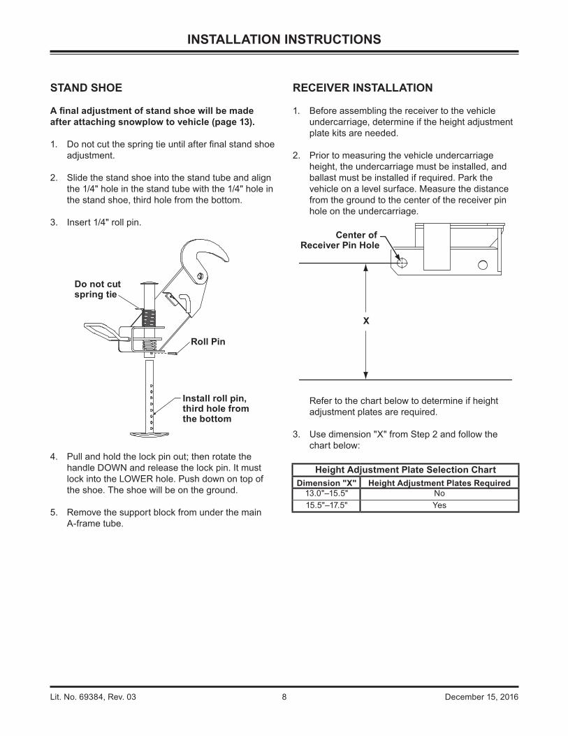
RECEIVER INSTALLATION
1. Before assembling the receiver to the vehicle undercarriage, determine if the height adjustment plate kits are needed.
2. Prior to measuring the vehicle undercarriage height, the undercarriage must be installed, and ballast must be installed if required. Park the vehicle on a level surface. Measure the distance from the ground to the center of the receiver pin hole on the undercarriage.
Refer to the chart below to determine if height adjustment plates are required.
3. Use dimension "X" from Step 2 and follow the chart below:
Height Adjustment Plate Selection ChartDimension "X" Height Adjustment Plates Required
13.0"–15.5" No15.5"–17.5" Yes
Center of Receiver Pin Hole
X
STAND SHOE
A final adjustment of stand shoe will be made after attaching snowplow to vehicle (page 13).
1. Do not cut the spring tie until after final stand shoe adjustment.
2. Slide the stand shoe into the stand tube and align the 1/4" hole in the stand tube with the 1/4" hole in the stand shoe, third hole from the bottom.
3. Insert 1/4" roll pin.
4. Pull and hold the lock pin out; then rotate the handle DOWN and release the lock pin. It must lock into the LOWER hole. Push down on top of the shoe. The shoe will be on the ground.
5. Remove the support block from under the main A-frame tube.
Roll Pin
Install roll pin, third hole from the bottom
Do not cutspring tie

Lit. No. 69384, Rev. 03 9 December 15, 2016
INSTALLATION INSTRUCTIONS
4. If adjustment plates are required, install as follows: Position an adjustment plate on each side of the receiver as shown. Insert a 3/4" x 2-3/4" cap screw through the lower front adjustment plate hole and through the appropriate hole on the receiver. Secure with a locknut.
Insert a cap screw through the rear adjustment plate hole, through the slot on the receiver. Secure with a locknut. Repeat for the passenger's side. Tighten all fasteners according to the torque chart.
5. Position the receiver between the mount brackets on each side. Align the notches in rear of the receiver with pins in vehicle undercarriage. Rotate up and secure with a 3/4" x 4-3/8" clevis pin and hairpin cotter on each side. If the height adjustment plates are not used, insert the spacer provided between the receiver and the inner-most mount bracket.
Shown without adjustment plate.
Shown with adjustment plate installed.
Adjustment PlateReceiver
3/4" x 2-3/4" Cap Screws
3/4" Locknuts Adjustment Plate
3/4" x 4-3/8" Clevis Pin
Cotter Pin
Spacer
Cotter Pin
3/4" x 4-3/8" Clevis Pin
AdjustmentPlate

Lit. No. 69384, Rev. 03 10 December 15, 2016
INSTALLATION INSTRUCTIONS
HEADLAMPS
Headlamps, hardware and instructions are found in the headlamp box. Additional hardware is found in the loose parts box.
Refer to figure above for the following instructions.
1. Remove the zip ties securing light bar to lift frame.
2. With the wire harness behind the lift frame, attach the headlamps to the hole and slot in the light bar by following the instructions included with the headlamps.
Cable Ties
PlowBatteryCable
Grommet Headlamp Harness
3. Insert seven cable tie anchors into 1/4" holes on the rear of light bar from the inside, with the locking tabs horizontal.
4. Install a split rubber grommet on each headlamp wire 3" from headlamp and insert grommet and wire into slot on rear of light bar.
5. Route the wires underneath the light bar, behind the vertical supports, and down along the inside of the driver-side vertical support, securing the wires to the anchors with cable ties.
WARNINGYour vehicle must be equipped with snowplow headlamps and directional lights.
Lit. No. 69384, Rev. 03 11 December 15, 2016
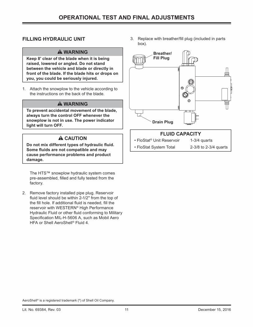
FILLING HYDRAULIC UNIT
1. Attach the snowplow to the vehicle according to the instructions on the back of the blade.
The HTS™ snowplow hydraulic system comes pre-assembled, filled and fully tested from the factory.
2. Remove factory installed pipe plug. Reservoir fluid level should be within 2-1/2" from the top of the fill hole. If additional fluid is needed, fill the reservoir with WESTERN® High Performance Hydraulic Fluid or other fluid conforming to Military Specification MIL-H-5606 A, such as Mobil Aero HFA or Shell AeroShell® Fluid 4.
3. Replace with breather/fill plug (included in parts box).
CAUTIONDo not mix different types of hydraulic fluid. Some fluids are not compatible and may cause performance problems and product damage.
FLUID CAPACITY• FloStat® Unit Reservoir 1-3/4 quarts• FloStat System Total 2-3/8 to 2-3/4 quarts
AeroShell® is a registered trademark (®) of Shell Oil Company.
OPERATIONAL TEST AND FINAL ADJUSTMENTS
WARNINGKeep 8' clear of the blade when it is being raised, lowered or angled. Do not stand between the vehicle and blade or directly in front of the blade. If the blade hits or drops on you, you could be seriously injured.
WARNINGTo prevent accidental movement of the blade, always turn the control OFF whenever the snowplow is not in use. The power indicator light will turn OFF.
Breather/Fill Plug
Drain Plug

Lit. No. 69384, Rev. 03 12 December 15, 2016
OPERATIONAL TEST AND FINAL ADJUSTMENTS
BLADE DROP SPEED ADJUSTMENT
1. The plow drop speed may be adjusted by turning the quill.
NOTE: The blade will not drop when quill is fully tightened (clockwise). Turn OFF the plow control, turn the quill 1/8 turn outward (counterclockwise), then proceed with blade drop speed adjustment.
2. Lower the blade to the ground before making adjustment.
WARNINGKeep 8' clear of the blade when it is being raised, lowered or angled. Do not stand between the vehicle and blade or directly in front of blade. If the blade hits or drops on you, you could be seriously injured.
3. Turn the quill inward (clockwise) to decrease the drop speed. Turn the quill outward (counterclockwise) to increase the drop speed.
4. Stand 8' clear of the blade when checking adjustment.
Quill

Lit. No. 69384, Rev. 03 13 December 15, 2016
OPERATIONAL TEST AND FINAL ADJUSTMENTS
FINAL INSPECTION AND ADJUSTMENT
1. Attach snowplow to the vehicle mount. With snowplow lowered to the ground and on level pavement, measure the dimension from the ground to the bottom of the A-frame side tube. This dimension must be 8-1/2"–10-1/8".
2. With the snowplow attached and on the ground, place the stand arm in the lower position with the lock pin engaged and with the stand shoe fully retracted in the "UP" position. Measure the distance from the ground to the bottom of the stand shoe. This distance should be 1-3/8"–2-1/8". The stand can be adjusted to achieve this dimension by removing the roll pin and selecting the proper hole in the stand stem. When the stand height is correct, cut and remove the spring tie.
3. Fully angle the blade in both directions in raised and lowered positions. Adjust hose fittings, wraps and clamps so hoses do not contact vehicle bumper, have no sharp bends and are wrapped at contact points with the lift and A-frames.
1-3/8" to 2-1/8"
Roll Pin 8-1/2" to 10-1/8"
Stand Shoe
Stand Arm
Stand ShoeStand Arm
Lit. No. 69384, Rev. 03 14 December 15, 2016
VEHICLE LIGHTING CHECK
1. Verify the operation of all vehicle front lighting prior to connecting the snowplow harness.
2. Check the operation of the snowplow lights with snowplow mounted to vehicle and all harnesses connected.
Turn signals and parking lamps
Parking lamps ON:• Both vehicle and snowplow parking lamps
should be ON at the same time.
Driver-side turn signal ON:• Both vehicle and snowplow driver-side turn
signal lamps should flash at the same time.
Passenger-side turn signal ON:• Both vehicle and snowplow passenger-side
turn signal lamps should flash at the same time.
Headlamps
Move vehicle headlamp switch to the "ON" position. Connecting and disconnecting the snowplow lighting harness plug should switch the lights between vehicle and snowplow as follows:
Snowplow lighting harness DISCONNECTED:• Vehicle headlamps should be ON.• Snowplow headlamps should be OFF.
Snowplow lighting harness CONNECTED:• Snowplow headlamps should be ON.• Vehicle headlamps should be OFF.
Dimmer switch should toggle headlamps between high and low beams. The high beam indicator on the dash should light when headlamps are placed in high beam.
Daytime Running Lamps (DRLs)
An operational check of the vehicle and snowplow DRLs will depend on the vehicle model, vehicle DRL system and type of Isolation Module installed. Due to the variations in the OEM DRL systems and the different Isolation Module
options available, checking the functionality of the snowplow DRLs will depend on the type of module installed on the vehicle.
With headlamp switch OFF, activate the vehicle DRLs.
Snowplow lighting harness DISCONNECTED:• Vehicle DRLs should be ON.• Snowplow headlamps should be OFF.
Snowplow lighting harness CONNECTED and vehicle in DRL mode:
• Check snowplow DRL function per the type of Isolation Module installed.
Refer to the Electrical Schematics Guide for information on the Isolation Module DRL functions.
Hand-Held Control
The snowplow plugs do need to be connected to the vehicle harness connectors. The control power indicator light should light whenever the control ON/OFF switch and the ignition (key) switches are both in the "ON" position.
3. Connect all snowplow and vehicle harnesses. Raise the snowplow and aim snowplow headlamps according to the Snowplow Headlamp Beam Aiming instructions included with the headlamps and any state or local regulations.
4. Check aim of vehicle headlamps with snowplow removed.
5. When the snowplow is removed from the vehicle, install plug covers on the vehicle battery cable and lighting harness. Insert the snowplow battery cable and lighting harness into the cable boot on the snowplow.
OPERATIONAL TEST AND FINAL ADJUSTMENTS
CAUTIONOn 2-plug electrical systems, plug covers shall be used whenever snowplow is disconnected. Vehicle Battery Cable is 12-volt unfused source.

Lit. No. 69384, Rev. 03 15 December 15, 2016
OWNER'S MANUAL PACKET
If the completed snowplow will be delivered immediately, the Owner's Manual should be reviewed with and given to the purchaser according to the snowplow checklist.
If the snowplow is completed prior to delivery to the purchaser, attach the Owner's Manual Packet to the electrical cable of the cab control for safekeeping.
OPERATIONAL TEST AND FINAL ADJUSTMENTS

Lit. No. 69384, Rev. 03 16 December 15, 2016
Western Products reserves the right under its product improvement policy to change construction or design details and furnish equipment when so altered without reference to illustrations or specifications used. Western Products or the vehicle manufacturer may require or recommend optional equipment for snow removal. Do not exceed vehicle ratings with a snowplow. Western Products offers a limited warranty for all snowplows and accessories. See separately printed page for this important information. The following are registered (®) or unregistered (™) trademarks of Douglas Dynamics, LLC: FloStat®, HTS™, UltraMount®, WESTERN®.
Printed in U.S.A.
A DIVISION OF DOUGLAS DYNAMICS, LLC
Western ProductsPO Box 245038Milwaukee, WI 53224-9538www.westernplows.com