IDEM Wellhead Protection Program Guidance Document
128
Transcript of IDEM Wellhead Protection Program Guidance Document


Acknowledgements
This document has been completed through the efforts of staff from the Ground Water Section,Drinking Water Branch, Indiana Department of Environmental Management. Key staff membersinvolved include Mr. Paul Johnson (Chief of the Drinking Water Branch), Mr. Robert Duncan ( Chief of the Ground Water Section ), Ms. Lynne McCaffry-Newlon (Wellhead ProtectionCoordinator), Ms. Mary E. Hoover (Wellhead Hydrogeologist), Dr. Mohammad Iqbal (formerWellhead Hydrogeologist), and Martha Clark (Ground Water Protection Planner).
In addition, the authors would like to thank the contributions of several others within or formerlyassociated with IDEM; namely, Mr. T.P. Chang (former Chief of the Drinking Water Branch),Mr. Steve Roush (former Chief of the Ground Water Section) and Mr. Bob Hilton (former Chiefof the Drinking Water Branch). Several others have provided significant contributions to theprogram, these are Mr. Bill Dillon and Mr. John Stancati (South Bend Water Works), Mr. GaryGilot (City of Elkhart), Mr. Mike Littlejohn (Speedway Water Works), Ms. Victoria Warren andMr. Tim Bannister (EMCON, Inc.), Ms. Becki Moffett-Moore and Ms. Karen Mackowiak(MACOG), and Ms. Pat Spence (HNTB).
The Ground Water Section would also like to thank the members of the Indiana Ground WaterTask Force, the Wellhead Protection Workgroup, and the American Water Works Association -Indiana Section, Indiana Water and Wastewater Association, and the Indiana Rural WaterAssociation for their advice and guidance. Also, the contributions from numerous waterpurveyors, well drillers, consultants, and representatives from local government provided greatinsight to the perspectives of the water supply system in developing a State-wide WellheadProtection Program.
Special thanks go to Mrs. Margaret Kiefer for her assistance in preparing the numerous programdrafts and final manuscript. Also, special recognition goes to Mr. J.C. Alexander (IDEM - FieldInspection Section) and Mr. Mitt Denney (Ground Water Section) for the cover art and graphics.
These acknowledgements would not be complete without thanking all of those involved inproviding comments on the previous drafts of the program. These comments have greatlyenhanced the final document and have helped shape Indiana’s program. Special thanks go out toMs. Jerri-Anne Garl, Ms. Rita Bair, Ms. Rebecca Groulx, and Mr. Paul Johnson of the GroundWater Protection Branch, U.S. Environmental Protection Agency, Region 5 for their efforts inproviding guidance and assistance to the Ground Water Section in developing Indiana’s WellheadProtection Program.
TABLE OF CONTENTS
I. INTRODUCTION
II. ROLES, RESPONSIBILITIES and AUTHORITIES
III. DELINEATION OF WELLHEAD PROTECTION AREAS IV. IDENTIFICATION AND INVENTORY OF POTENTIAL SOURCES OF
CONTAMINATION
V. MANAGEMENT APPROACHES OF WELLHEAD PROTECTION AREAS
VI. WHPP CONTINGENCY PLANS
VII. NEW WELLS
VIII. NON-COMMUNITY WELLS
IX. PUBLIC PARTICIPATION

FIGURESPage
1. Community Water Systems Served by Groundwater.....................................................I-2
2. Non-Community Water Systems Served by Groundwater.............................................I-3
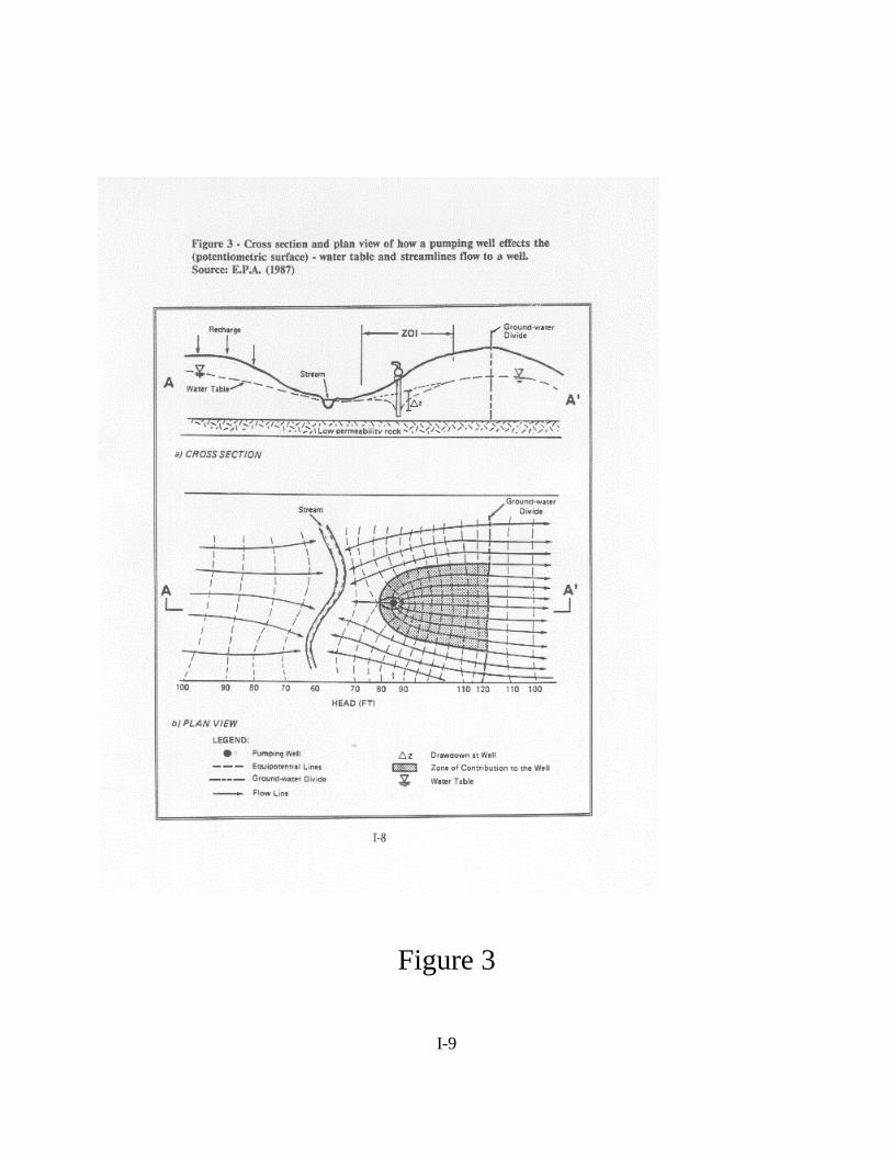
3. How a Pumping Well Effects the Water Table ..............................................................I-8
4. Comparison of Delineation Methods .......................................................................... III-7
5. Example of a Source Inventory Map........................................................................... IV-7
LIST OF TABLES
Page
I.1 Wellhead Protection Overview ....................................................................................I-6
III.1 Rational for Method Selection .................................................................................. III-2
III.2 Comparison of Delineation Methods and Method Eligibility................................................................................................................... III-6
IV.1 Potential Contaminant Sources ................................................................................. IV-2
IV.2 Recommended Inventory Procedures........................................................................ IV-3
IV.3 Example Reporting Format for Potential Source Inventories ................................... IV-6
VIII.1 Examples of Non-Community Water Systems....................................................... VIII-2
APPENDICES
1. References ................................................. . . . . . . . . . . . . . . . . . . . . . . . . . . . . . . APX I-1
2. Delineation Considerations ..................................................................................APX II-1
3. Abbreviations and Acronyms............................................................................. APX III-1
4. Arbitrary Fixed Radius Summary Report . . . . . . . . . . . . . . . . . . . . . . . . . . . . APX IV-1
5. 327 IAC 8-4.1-- Wellhead Protection Rule. . . . . . . . . . . . . . . . . . . . . . . . . . . . . . APX V-1
INTRODUCTION
A. Statutory and Policy Basis.............................I-4
B. Program Overview.........................................I-5
C. Wellhead Protection Submittal.......................I-10
D. State Role.......................................................I-14
-1
WELLHEAD PROTECTION: .............................................A PROGRAM FOR THE STATE OF INDIANA
I. INTRODUCTION
Ground water supplies approximately 60% of Indiana’s public drinking water. In addition,ground water is considered the primary resource to supply future drinking water needs in order tosupport the State’s growing population. To provide for a safe supply of drinking water, the Stateof Indiana is undertaking a Wellhead Protection Program (WHPP) to protect ground waterresources used for drinking water purposes. Requirements for drinking water quality placed onpublic water supply systems (PWSSs) by the federal Safe Drinking Water Act (SDWA) aredifficult to adhere to with monitoring and treatment alone. Based on this, they advanceprevention as a means to help PWSSs achieve drinking water standards on a consistent basis. Prevention of contamination is acknowledged as an efficient and effective means, botheconomically and technically, of maintaining safe drinking water for the citizens of Indiana.
Presently, there are approximately 4,500 PWSSs operating in Indiana that derive their supplyfrom ground water. Community public water supply systems (CPWSS) account for roughly 900of the total number of public water supplies (Figure 1). A CPWSS is defined by the federal SafeDrinking Water Act as a system which possesses at least 15 service connections or supplies waterto at least 25 people on a continual basis. The remaining number of systems consists of transientand non-transient non-community water supplies (Figure 2).
Historically, the State of Indiana has considered public water supplies as a high priority forprotection. Since the 1930’s, Indiana has instituted an informal policy requiring a 200 footminimum separation distance between a public water supply system ( PWSS) well or well fieldand sources of bacteriological contamination (e.g., sanitary sewers). Presently, a well siteapproval for new wells and well fields is issued by the Department of EnvironmentalManagement (IDEM) as a condition of acquiring a well construction permit. The well siteapproval process includes an assessment of land use within a 3,000 foot radius of the proposedwell or well field to consider other potential sources of contamination, such as chemicalpollutants.
In addition to the well site survey process, Indiana’s solid waste rule requires proposed solidwaste landfills to be located at least 3,000 feet from a PWSS well. Other minimum sitingrequirements are incorporated into State source control programs, such as on-site sewagedisposal systems. While these procedures provide measures of protection, the WellheadProtection Program is a more progressive approach to protecting public water supplies fromcontamination, which considers not only the location of the well, but the surface area above thesubsurface zone contributing water to the well under pumping conditions.

-2
Figure 1.

-3
Figure 2.

-4
A. Statutory and Policy Basis
The 1986 Amendments to the federal Safe Drinking Water Act require States to formally protectground water that supplies public water systems. Section 1428 of the SDWA requires States todevelop plans that describe the following elements:
1. Duties of State and local agencies and PWSSs in implementing the program;
2. Determination of wellhead protection areas (WHPAs) for each public well or wellfield;
3. Identification of all potential anthropogenic sources within the protection area;
4. A program that contains, as appropriate, technical assistance, financial assistance,implementation of control measures, education, training, and demonstration projectsto protect wellhead areas from contaminants;
5. Contingency plans for alternative water supplies in case of contamination;
6. Siting consideration for all new wells; and
7. Public participation.
Authority for approval of State programs was provided to the Administrator of the U.S.Environmental Protection Agency (EPA). To assist States in the development of WHPPs,guidance describing the various components of a State’s program has been developed by EPA.
In response to the requirements of Section 1428 of the federal SDWA, the State of Indianaidentified wellhead protection as a priority in the Ground Water Quality Protection andManagement Strategy developed in 1987. To formalize Indiana’s commitment to the protectionof public water supplies, the 1989 Ground Water Protection Act [IC 13-18-17-6] authorized theWater Pollution Control Board to establish regulations to protect community PWSS well fieldsfrom contamination [IC 13-7-26-7].
To support the policy advanced in the 1987 Strategy, the provisions of the 1989 GWPA, and therequirements of the federal SDWA, Indiana has developed a program that describes the State’spolicy toward preventing contamination within the area contributing water to a PWSS well. Prevention is addressed through activities performed by State, federal, and local government andaction by a PWSS.
Indiana’s approach to Wellhead Protection (WHP) consists of a mandatory component for thedevelopment of local programs for CPWSSs. In this, community systems will be required tomeet the minimum elements of community planning, delineation, source identification,management of potential sources, and contingency planning. The specific requirements under

I-5
each element are described throughout the remainder of this document. In addition to themandatory approach for community systems, non-community PWSSs are encouraged to developWHPPs through voluntary participation. Where non-community systems develop WHP plans,the State will endorse the program where a non-community system’s plan is consistent with therequirements of a community system.
B. Program Overview
The purpose of this document is to describe the State’s approach to protect public water suppliesfrom contamination under the various elements prescribed by the federal SDWA. BecauseIndiana’s approach consists of actual implementation at the local or system level, it is imperativefor the program to provide an overview describing the steps necessary for systems to initiate,develop, and ultimately implement a WHP plan. In addition, the various activities the State willpursue to provide a consistent and effective level of protection of public water supplies must beoutlined.
In understanding the difference between development and implementation, Indiana recognizes aneffective program may not be able to evolve in a relatively short period of time. To provide forthis, Indiana’s program will support a phased process for implementation of the managementmeasures a PWSS intends to undertake to minimize the potential for contamination from aspecific source.
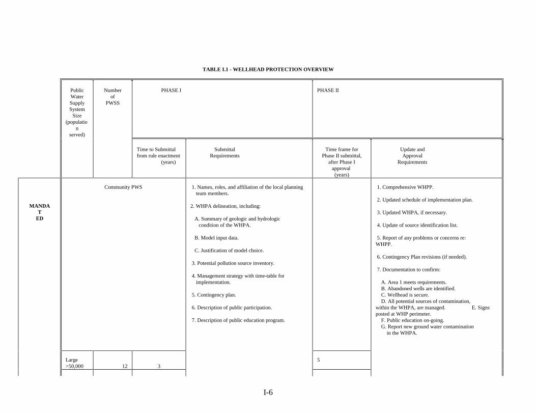
Therefore, Phase I of the Indiana WHPP comprises the basic elements of community planning,delineation, source inventory, and contingency planning for contamination events (Table I.1). Inaddition to these basic elements, a community water supply must describe the managementmeasures it intends to undertake for all potential sources identified in its WHPA. In Phase II, acommunity system must document how the proposed management measures have been or arebeing implemented. An adequate period of time is allocated for implementation, where smallersystems are allowed a longer implementation period than larger systems (Table I.1).
I-6
TABLE I.1 - WELLHEAD PROTECTION OVERVIEW
PublicWaterSupplySystem
Size(populatio
nserved)
Numberof
PWSS
PHASE I PHASE II
Time to Submittalfrom rule enactment
(years)
SubmittalRequirements
Time frame forPhase II submittal,
after Phase Iapproval (years)
Update andApproval
Requirements
MANDAT
ED
Community PWS 1. Names, roles, and affiliation of the local planning team members.
2. WHPA delineation, including:
A. Summary of geologic and hydrologic condition of the WHPA.
B. Model input data.
C. Justification of model choice.
3. Potential pollution source inventory.
4. Management strategy with time-table for implementation.
5. Contingency plan.
6. Description of public participation.
7. Description of public education program.
1. Comprehensive WHPP.
2. Updated schedule of implementation plan.
3. Updated WHPA, if necessary.
4. Update of source identification list.
5. Report of any problems or concerns re: WHPP.
6. Contingency Plan revisions (if needed).
7. Documentation to confirm:
A. Area 1 meets requirements. B. Abandoned wells are identified. C. Wellhead is secure. D. All potential sources of contamination, within the WHPA, are managed. E. Signsposted at WHP perimeter. F. Public education on-going. G. Report new ground water contamination in the WHPA.
Large>50,000 12 3
5

I-7
PublicWaterSupplySystem
Size(populatio
nserved)
Numberof
PWSS
PHASE I PHASE II
Time to Submittalfrom rule enactment
(years)
SubmittalRequirements
Time frame forPhase II submittal,
after Phase Iapproval (years)
Update andApproval
Requirements
Medium3,300 to50,000
166
4 7
Small<3,300 71
7
5
10
Total 895
3-5 5-10
VOLUNTARY
Non-Community PWS
Non-Transient 61
0N/A 10 years following
Phase I Submittal
Transient 3169
N/A
GRAND TOTAL 46
743-5
8-15

I-8
1. Local Planning Team
The initial step required to develop a WHP plan is the organization of theappropriate people to plan the system’s or community’s approach to WHP. A localplanning team (LPT) must be organized to provide support to decisions relevant tothe various aspects of a local WHP plan. It is recommended that appropriaterepresentatives from all perspectives of wellhead protection be a part of the localplanning team. It is mandated that a minimum of one (1) person that may beaffected by the development and implementation of the WHP be a member of theLPT.
The local planning team should guide the process for delineation of the WHPA, identification of potential sources of contamination, the determination of specific management measures to be implemented, and the development of a contingency plan to provide for emergencies resulting from contamination events.
2. WHPA Delineation
Deciding how to delineate the WHPA is an initial activity of the local planningteam. The purpose for delineation is to appropriately determine the area forimplementing activities to protect the water supply from contamination. Themethods for delineation recognize the system’s need to accurately define the areacontributing water to the well or well field (Figure 3). Numerous decisions areintrinsic to the delineation process, the incorporation of future water supply needs,the hydrogeologic data needed to adequately support the delineation, etc. Theminimum requirements for delineation, including the information necessary tojustify the method selected, are provided in the Delineation section of this document (Section III). Guidance for systems in the selection of an appropriate delineationmethod will be developed by the IDEM.
I-9
Figure 3

I-10
3. Source Identification
Following the delineation step, the system should undertake a program foridentifying all potential sources of contamination located within the delineatedWHPA. A source inventory (source I.D.) should consist of the informationnecessary to manage the potential source to prevent contamination. Thisinformation should include: a map locating the identified sources, the type ofactivity performed at the site, chemicals stored or handled on-site, and whether thefacility is regulated by local, State, or federal agencies. Several methods forundertaking a source inventory are described in the Source Identification section ofthis document (Section IV).
4. Management Strategy
Following the delineation and potential source inventory steps, the system shoulddetermine appropriate measures to manage all potential sources within the WHPA. A plan, with corresponding schedule for implementation, should be developed bythe system, or, more appropriately, the local planning team. Requirements forpotential source management are described in the Management section of thisdocument (Section V).
5. Contingency Plan
In addition to the above steps, the system must develop a plan to provide forcontingencies when there is an emergency resulting in contamination to the well orwithin the delineated WHPA. This plan generally consists of a list of emergencyphone numbers, agreement with local or State emergency response programs tocontact the PWSS in case of contamination events, and procedures to follow whencontamination occurs. A plan for providing alternative sources of water should alsobe developed. This program provides the necessary elements of a WHP contingencyplan in Section VI of this document. Additionally, the IDEM will develop guidancefor developing a comprehensive contingency plan that considers all emergenciesthat may be encountered by a PWSS.
6. New Wells
To insure new wells and well fields are properly sited, the concepts of wellheadprotection should be incorporated into the design phase of a well field. To supportthis philosophy, the State of Indiana will revise its construction permittingprocedures to include preliminary delineation (e.g., 3,000 foot radius) and sourceidentification before the well site is approved. The well site approval procedureshave been incorporated into the WHP regulations as a requirement for all new well

I-11
site development. Specifics on the new well construction permit procedures can befound in Section VII of this document.
C. WHPP Submittal
1. Phase I
The CPWSS must submit a WHP plan describing the system’s delineation, sourceinventory, strategy for management of potential sources of contamination, andcontingency plan to the Indiana Department of Environmental Management(IDEM), Drinking Water Branch for review. A Phase I WHP plan will constitute anapplication to the IDEM for approval of the system’s plan for wellhead protection. The IDEM review of a PWSS’s proposed plan for wellhead protection will be basedon determining the appropriateness of the delineation, the comprehensiveness of thesource inventory (primarily whether the source inventory provides the informationnecessary to support management decisions), the adequacy of the management planto protect the well or well field from contamination, and the comprehensiveness ofthe contingency plan. The IDEM’s review will also insure compliance of thesystem's plan with the minimum requirements listed in this document and theState’s WHP regulation (327 IAC 8- 4.1).
In addition to a formal review of the adequacy of the system's plan, the IDEM will initiate a site visit to observe the characteristics of the WHPA, and obtain accuratelocational information on the well or well field through the use of global positioningsystem (GPS) equipment. An accurate location of the well or well field will providea greater degree of protection by allowing the various State source control orremedial programs to recognize public water supplies with respect to siting facilitiesor developing effective remediation plans.
After review, PWSSs which demonstrate an adequate WHP plan will be awarded aformal plan approval by the IDEM. Approval of local WHP plans will becontingent on the system's commitment to implementing the management measuresoutlined in the management plan.
The Phase I Submittal package will consist of the following (specific criteria foreach portion of the submittal are provided in the remaining portions of thisdocument):
a. Application form for Phase I (currently under development by theIDEM);
b. A brief background of the public water supply system, thecommunity serviced, including a discussion of the local planning
I-12
team, any specific committees and their duties, and theteam/committee membership;
c. A map of the delineated wellhead protection area (WHPA) -- to ascale between 1"= 400’ and 1"= 1,000’ -- and a summary reportdetailing the geologic and hydrogeologic conditions of the area andsupporting data for the delineation (for systems not using fixedradius);
d. A source inventory, in tabular form, that describes the nature,location, and status of potential sources of contamination existingwithin the delineated WHPA. An accompanying map, which must reference the tabular inventory, is required. This source inventorymap may be the same as the delineation map, as long as all identifiedsources are plotted on this map;
e. A strategy for management of all potential sources identified, whichincludes a schedule for implementation of the proposed potentialsource management measures;
f. A contingency plan for contamination within the delineated WHPA;
g. A summary of the efforts of the PWSS and/or local planning team toinvolve public participation in decisions for wellhead protection; and
h. A summary of the public education/outreach program instituted bythe PWSS, community, and/or local planning team.
These components comprise an application to the Commissioner of the IDEM forapproval of the system’s Phase I Wellhead Protection Plan. All componentsoutlined must be submitted with the Phase I application, or the application will berejected on the basis of incompleteness. The IDEM will approve or disapprove ofthe material submitted within one-hundred and eighty (180) days from submission.
2. Phase II
Following approval of a Phase I WHP plan, CPWSSs will be required to initiate themanagement of potential sources according to the schedule proposed in themanagement plan. Approval of a Phase II WHPP will be awarded by the IDEMwhen the system has demonstrated management of all potential sources as proposedin the management plan. This demonstration will be documented in an applicationfor approval of Phase II. However, a Phase II approval does not indicate theconclusion of wellhead protection; continual implementation of the management

I-13
measures must be maintained. The time frame for the Phase II submittal will startafter the Phase I WHP plan is approved.
To encourage continual implementation of potential source of contaminationmanagement within a WHPA, the IDEM will institute a regular status reportingmechanism to identify problems and determine where assistance is needed. On afive-year basis, all systems developing or implementing WHP plans (including non-community systems voluntarily participating in the program) will be required tosubmit a succinct report on the status of the development or implementation of theirlocal WHP plan.
The Phase II submittal package consists of the following components:
a. Application form for Phase II approval (currently under developmentby IDEM);
b. A discussion of updates to the approved Phase I Wellhead ProtectionPlan, such as the following:
· The background of the PWSS, community, and local planningteam;
· An updated WHPA delineation, if performed due toconsideration of new data;
· An updated source inventory, including a revised table andmap showing the present status of existing or new potentialsources within the delineated WHPA; and
· A revised contingency plan, if changed since the Phase Iapproval, and documentation of training givento local responders.
c. Documentation of the implemented management strategy, whichexhibits the following:
· The sanitary setback area meets requirements;· All abandoned wells not in compliance with
I C 25-39-4-6, are identified;· The wellhead is secure;· All potential sources identified are properly managed --
through the measures proposed in the approved Phase Imanagement strategy;
· Signs are posted at the WHPA perimeter on majorthoroughfares;
• An ongoing public education and outreach program exists;
I-14
and· New or existing ground water contamination in the WHPA is
reported.
These components comprise an application to the Commissioner of the IDEM for approvalof the system's Phase II Wellhead Protection Program. All components described abovemust be submitted with the Phase II application, or the application will be rejected on thebasis of incompleteness. The IDEM will approve or disapprove the materials submittedwithin one hundred eighty (180) days after submission.
3. Submittal Time Frames
The time-frame for submittal of both the Phase I and Phase II applications are provided inTable I.1. The time period identified for each system type are in years from the effectivedate of the WHP rule (327 IAC 8-4.1-16). The following provides a narrative of thesubmittal schedule:
a. Phase I submittals are as follows:
• All materials must be submitted within three (3) years for largeCPWSS; ( > 50,000 ) population served;
• All materials must be submitted within four (4) years for mediumCPWSS; ( 3,301 to 50,000 ) population served;
• All materials must be submitted within five (5) years for smallCPWSS. (<3,300 ) population served.
b. Phase II submittals are as follows:
• All materials must be submitted within five (5) years afterdepartment approval of Phase I material for large CPWSS;
• All materials must be submitted within seven (7) years afterdepartment approval of Phase I material for medium CPWSS;
• All materials must be submitted within ten (10) years afterdepartment approval of Phase I material for small CPWSS.
The department will provide written approval or denial of the PWSS's submittal within one-hundred eighty (180) days from submission.
I-15
D. State Role
The State’s efforts in WHP will not be limited to approval of new wells, coordination of regulatory source information, and review of local wellhead protection plans. The role of
the State is to provide a consistent and effective level of source control and management.Current source control regulations implemented by State and local government generally provideminimum setback distances for sources from PWSS wells. However, many of these setbackdistances are inconsistent. The intention of the State is to work within the current and proposedregulatory framework to coordinate the requirements of the WHPP and the management criteriaimposed by source control regulations.
To affect this coordination, the IDEM, Drinking Water Branch will work with all State sourcecontrol and management programs during rule development and revision efforts to integrate themanagement concepts of the WHPP into the source control rule framework. Integration of sourcecontrol regulations with the WHPP will assist PWSSs in the implementation of their managementplan. In effect, the management of State and federally regulated potential sources of contaminationwill be implemented by the relevant regulatory agency, thereby reducing the entire burden forsource management of the PWSS. In addition, the IDEM will work with all existing State andfederal source control programs to track permits and other site-related information to providePWSSs with accurate information on the location of regulated facilities within WHPAs.
To further assist PWSSs in the development of local programs, the IDEM-Drinking Water Branchwill undertake an aggressive public education and outreach program. Workshops on WHPconcepts such as delineation, source inventory procedures, and management of potential sourceswill be offered by the IDEM. Assistance to PWSSs will be precipitated, in part, through the statusreporting process. Specifically, a standard reporting format will be developed which will providethe IDEM insight to the issues encountered by PWSSs in the development and implementation oflocal plans. The IDEM will be tracking the implementation status of approved WHP plans. Moredetails of tracking can be found in Section V of the program. Direct technical assistance will beprovided to all systems requesting support on the development or implementation of their localplan.
The concept of WHP is to advance a prevention-oriented approach to providing safe drinking waterto the citizens of Indiana. This effort builds on the current and historic priority the State has placedon safe drinking water.

II. Roles, Responsibilities and Authorities
A. Public Water Supply Systems.....................................II-1
B. Local Government......................................................II-1
C. State Government.......................................................II-2
D. Federal Agencies........................................................II-8
E. Regional Planning Agencies.......................................II-9
F. Local Level Groups....................................................II-9
G. Local Planning Team................................................II-10

-1
II. ROLES, RESPONSIBILITIES AND AUTHORITIES
A. Public Water Supply Systems:
Public water supply systems (PWSSs) will be responsible for preparing local wellheadprotection (WHP) plans and implementing programs to help protect wells which they ownand manage. Community PWSSs are required to develop and implement wellheadprotection plans. The Wellhead Protection Program (WHPP) is voluntary for non-community systems; however, if non-community PWSSs decide to apply for approval, theirWHP plans must meet the guidelines established by the IDEM in this program document.
As part of the WHP plan, the PWSS will be required to:
· Develop a local Wellhead Protection planning team;· Delineate the wellhead protection area (WHPA);· Inventory potential contamination sources within the WHPA;· Develop a strategy to manage potential contamination threats within the
WHPA;· Develop an implementation plan;· Develop a contingency plan to protect the water supply in emergency
situations;· Conduct public outreach programs to educate community members and
owners of potential sources of contamination of the consequences ofcontamination to the drinking water aquifer and practices which can protectthe aquifer; and
· Track the activities of existing, as well as, new potential sources ofcontamination in the WHPA.
It is recognized that PWSSs which serve municipalities but are privately owned mayexperience difficulty in establishing and operating WHP plans based on municipalauthority. The primary obstacle is their limited ability to mandate land use outside the areathey own. Because of this, it will be critical for privately owned PWSSs to establish a closeworking relationship with the municipality they serve. In particular, it is necessary for theplanning team to include local government officials.
B. Local Government
Ideally, a local government representative should serve on the local planning team to assurecommunication between local government agencies. Also, local governments can act as coordinators of WHP activities when WHPAs extend across adjacent political boundaries.
-2
C. State Government
Under the WHPP, the State will have the responsibility to review the local WHP plans andprograms including the approval of new well sites. The State will provide the guidelinesfor developing a comprehensive WHP plan and provide information and technical guidancefor the locally initiated public education outreach program. The State will provide technicalassistance documents to assist in the development of a WHP plan. The State will also havethe responsibility to control the State regulated facilities within the WHPA to protectground water from contamination. The State will participate in and facilitate thecoordination of relevant authorities in inter-state issues. The State will develop groundwater education materials which will be used by PWSSs in their public education programs.
1. Indiana Ground Water Task Force
The Indiana Ground Water Task Force was formed in 1989 as a result of the IndianaGround Water Protection Act (IC 13-7-26). The members of the Ground WaterTask Force (GWTF) consist of State agency heads including IDEM, IndianaDepartment of Natural Resources (IDNR), Indiana State Department of Health(ISDH), Office of the Indiana State Chemist (OISC) and Office of the State FireMarshal (OSFM) and five non-governmental representatives appointed by theGovernor. The five non-governmental members represent labor, agriculture, localgovernment, business, and environmental groups. According to the Indiana GroundWater Protection Act of 1989, the State agencies represented on the GWTF may notpermit activities within the protection areas (i.e., wellhead protection areas) thatwould violate or interfere with the purposes of the rules for well field protection. This implies that the agencies must notify each other when permitting a facility oractivity within a WHPA. During periods where the GWTF is in-active (e.g., whereappointments have not been made by the Governor’s office), the Task Force's WHPworkgroup will serve to provide the inter-agency coordination function of theGWTF.
The Indiana inter-agency GWTF is responsible for:
a. Studying ground water contamination in Indiana;
b. Coordinating the State agencies involved with ground water pollutionproblems;
c. Implementing the ground water quality protection and managementstrategy; and
d. Developing policies to prevent ground water pollution. The GWTF assigns specific technical issues to workgroups so that ground water
-3
protection policy may be developed. A wellhead workgroup was established in1990 by the GWTF, and the membership includes representatives from PWSSs,industry, environmental interest groups and local and state government. Theworkgroup was responsible for the identification of issues and potential policies toaddress in the WHPP. A subcommittee was formed to discuss delineation, in termsof guidelines, submittal requirements, and criteria for review. The workgroup hasprovided a mechanism to support the IDEM’s program development process. Inthis, the GWTF Wellhead Workgroup served to provide ideas and concepts to theIDEM during program development. In addition, the Wellhead Workgroup was theprimary review committee for the program to insure all perspectives of wellheadprotection are incorporated and the program represents a state-wide position.
2. Indiana Department of Environmental Management
The Indiana Department of Environmental Management (IDEM) will oversee andtrack WHP plan development and submittal, and coordinate with other regulatoryprograms.
Following are the program areas within the IDEM which will be affected by theState WHPP:
a. Office of Environmental Response
Emergency Response Branch: This Branch has the responsibility torespond to emergency situations associated with ground watercontamination. Such emergencies include accidental spills, leaks, releases ofhazardous materials above or below ground, etc., within an approved WHPAwhich may threaten the drinking water supply. In addition to responding inan emergency, this Branch will also be involved in prevention of such spillsor leakages.
Underground Storage Tank Branch: This Branch operates through twosections, the Underground Storage Tank Section (UST) and the LeakingUnderground Storage Tank (LUST) Section. The UST Section has theresponsibility to keep records of all underground storage tanks throughoutthe State and track tank construction standards. The LUST Section isresponsible for the remediation of the soil and ground water which has beencontaminated by a leaking tank. The LUST Section will prioritize theremediation of contaminated sites within approved WHPAs. Where underground tanks are located within an approved WHPA, the USTSection and the LUST Section will prioritize underground storage tanks in
those locations.

-4
Project Management Branch: This Branch is involved in theadministration and project management of voluntary clean-up, Superfund,and State Cleanup sites, and underground tank installation and removalactivities.
b. Office of Solid and Hazardous Waste Management
The Office of Solid and Hazardous Waste Management (OSHWM) isresponsible for regulating solid and hazardous waste facilities, such as ,landfills, transfers stations, and storage areas. The OSHWM will beresponsible for permitting, inspecting, investigating and overseeing clean upactivities of these facilities within WHPA’s. Geologist working for theoffice will work toward the proper siting and ground water monitoring ofthese facilities. Engineers within the office will ensure that the facilities areproperly designed. Inspection components for the office will enforce allappropriate permit conditions and rules ensuring appropriate operationstandards of these facilities. WHPAs have been and will continue to berecognized as areas of special concern with regards to solid and hazardouswaste management.
c. Office of Water Management
Drinking Water Branch: This Branch is responsible for:
· Development and administration of the WHPP and supportingregulations;
· Inter-agency coordination of the State WHPP between relevant stateagencies;
· Approval of well sites for new wells;· Maintenance of an updated inventory of all PWSSs within Indiana;· Coordination of state activities in case of local drinking water
emergencies, including the provision of maps and locations ofapproved WHPA’s to other IDEM, State, and Federal programs.
-5
Ground Water Section of the Drinking Water Branch will be directlyinvolved in:
· Review of WHP plans submitted by a PWSS;· Development of technical assistance and guidance documents for
delineation, contingency plans, new well site selection, potentialsource identification and management, and planning teams;
· Development of educational outreach programs for the public andPWS systems;
· Extension of technical assistance to the Compliance Section byproviding a ground water vulnerability assessment of the associatedWHPA for each waiver application;
· Development and presentation of technical workshops for PWSSs;· Review of new well sites and well site surveys (when adequate
funding becomes available); and· Geo-location of PWS wells, through the use of global positioning
system (GPS) equipment, in delineated WHPAs submitted forapproval.
Permit Section will be responsible for reviewing construction plans andspecifications, and issuing construction permits for new wells within theWHPA.
Compliance Section will be responsible for:
· Tracking the specific well site chemistry data before a waiver isapproved;
· Developing and updating the monitoring waiver package along withthe Ground Water Section.
Field Inspection Section will provide inspections of the well sites forsanitary surveys, and emergency ground water contamination situations, andprovide direct technical assistance to systems on water concerns. Untiladequate funding is available, the Field Inspection Section will continue itspresent role in field review and approval of new well sites.
Permits Branch: This Branch will be responsible for tracking facility compliance with existing water pollution regulations (i.e., NPDES).
-6
d. Office of Enforcement
This office will respond to all referrals from program areas for non-compliance problems associated with ground water contamination, solid andhazardous waste discharges, emergency response situations, etc. This officewill pursue formal enforcement actions against the non-complying PWSSs,when necessary.
e. Office of Pollution Prevention and Technical Assistance
This office develops policies and programs to reduce the generation ofmunicipal wastes, toxic materials and hazardous wastes and pollutants, bymeans of industrial pollution prevention within the WHPA. Pollutionprevention means the employment, by a business or commercial operation,of a practice that reduces the industrial use of toxic materials or reduces theenvironmental and health hazards associated with an environmental waste atits source, without diluting or concentrating the waste before its release,handling, storage, transport, treatment or disposal.
In conjunction with the Office of Water Management, Drinking WaterBranch (and various stakeholders), the Compliance and Technical AssistanceProgram’s Outreach and Education Branch will be developing an OutreachStrategy to help educate government agencies, PWSSs and communityrepresentatives on the importance of WHP and how to implement a localprogram.
3. Indiana Department of Natural Resources
The Department of Natural Resources is involved in ground water related activitiesof both a regulatory and resource evaluation nature. Three primary divisions areinvolved: Division of Oil and Gas, Division of Reclamation, and Division of Water.
The Division of Oil and Gas regulates the construction, drilling, and abandonmentof oil and gas wells, and injection wells (i.e., UIC Class II) that may be used todispose of brine waters recovered during the production of oil and gas.
The Division of Reclamation is involved in a variety of regulatory concerns,primarily coal mining activities impacting ground water. Data on ground waterquality, aquifer depth, yield, hydraulic characteristics, flow direction, etc. arerequired for the division’s permitting process.

-7
The Division of Water houses the database for Indiana’s water well records and is involved in studies of ground water resources based on geographical areas, such as
basin or county-wide studies, or locally in the case of special studies. Constructionstandards for water wells, monitoring wells and geo-thermal wells (including grouting andabandonment, etc.) have been established as part of the licensing and regulation of thewater well drillers. Water use data and information on high capacity wells is alsomaintained and is included in the management considerations of the State’s waterresources.
4. Indiana State Department of Health
The Indiana State Department of Health (ISDH) is responsible for generalsupervision and control of matters relating to the preservation and protection ofpublic health. Their programs include regulation of all on-site sewage disposalsystems which can directly impact local ground water quality and drinking watersafety. The ISDH works closely with the county health departments throughguidance and permitting of residential and commercial septic systems.
5. Office of the Indiana State Fire Marshal
The State Fire Marshal’s responsibilities concern the storage of materials whichpresent a fire or explosive hazard and on-site guidance to other officials whenemergency conditions involve a fire or explosion. The State Fire Marshal mustassure that flammable or explosive materials are stored in a manner to prevent fireand explosion hazards and make sure these hazardous substances are not dischargedto the ground water.
6. Office of the Indiana State Chemist
The Office of the Indiana State Chemist (OISC) regulates the use, storage, andapplication of registered pesticides, and the storage and containment of bulkfertilizers. Pesticide application restrictions are contained on federally-mandatedpesticide product container labels. Further restrictions on the use of a specificpesticides may be developed by the OISC through the Indiana Pesticide ReviewBoard.

-8
7. Other State Agencies
Other state agencies will cooperate with the IDEM to regulate potential contaminantsources within WHPAs and coordinate between parties involved in the process ofWHPP implementation.
Other state agencies involved in ground water protection are: the Indiana UtilityRegulatory Commission (IURC), the Department of Commerce (DOC), the IndianaGeological Survey (IGS), and the Indiana Department of Transportation (INDOT). The (IURC) reviews and determines requests for rate increases due to therequirements of the Wellhead Protection Program and regulations. The (DOC) mayprovide funding assistance for Wellhead Protection where funds are available. TheIGS will provide the IDEM and the OISC with ground water sensitivity maps andthe IGS will conduct a detailed hydrogeological study of selected well fields inwhich the vulnerability is not certain. The INDOT will oversee issues related toroad salt use and routing of hazardous cargo.
D. Federal Agencies
1. U.S. EPA
The United States Environmental Protection Agency (U.S. EPA) has theresponsibility to coordinate available grant support, technical assistance to Stateagencies regarding public domain computer software packages used for WHP, andprocedures for environmental risk assessment.
The U. S. EPA provides oversight authority for several source control programs(i.e., RCRA-C & D, NPDES, UIC-Class II, pesticide registration, etc.). The EPAwill continue oversight responsibilities for these programs and will coordinateregional and national priorities with the Indiana WHPP. In addition, the U.S. EPAprovides primary implementation authority for site clean-up of National Priority List(NPL) sites under the federal Superfund program and primary authority for thepermitting and enforcement of Class V underground injection wells. Further, theU.S. EPA provides oversight of the Indiana Public Water Supply Supervisionprogram. In this, EPA Region V will ensure effective coordination between thepriorities under the Public Water Supply Supervision program and the IndianaWHPP.
The U.S. EPA has established an information hotline for the Safe Drinking WaterProgram. This hotline provides assistance and regulatory information to the public,the regulated community, and PWSSs on regulations and programs developed inresponse to the SDWA Amendments of 1986. In addition, U.S. EPA wellhead

-9
protection documents may be requested through this hotline.
The U.S. EPA will thoroughly review the Indiana WHPP to assess the completenessof the program in accordance with the provisions of the SDWA, Section 1428. TheU.S. EPA will also provide technical assistance to all state agencies in both thedevelopment and implementation stages of the WHPP.
2. Other Agencies
The U.S. Geological Survey (USGS) and the United States Department ofAgriculture (USDA) Natural Resources Conservation Service (NRCS) providehydrogeological data and issue detailed maps containing technical informationnecessary for the delineation of WHPAs. The U.S. Department of Agriculturecooperative extension service provides technical assistance in managing agriculturalpractices which may adversely affect the quality of ground water.
Federal facilities are required to abide by state regulations. IDEM will be availableto advise and work with local PWSS’s serving federal facilities as needed.
E. Regional Planning Agencies
There are many regional planning organizations throughout Indiana which work on an arrayof regional issues. Regional planners typically coordinate efforts, such as transportationplanning, air quality, and water quality. Many issues are related to public water supplies,wastewater treatment, ground water protection and non-point source pollution. Theseagencies include:
· Michiana Area Council of Governments (MACOG),· Ohio-Kentucky-Indiana Regional Council of Governments (OKI),· Northwest Indiana Regional Planning Commission (NIRPC),· Ohio River Basin Sanitation Commission (ORSANCO).
F. Local Level Groups
A partnership between PWSSs and other local and county agencies should be a part of thedevelopment and implementation of WHP plans. Several different county and local officesmay participate in the local planning and implementation process, for example:
· Administrative officials,· County soil conservation districts,· County health department,
-10
· Fire marshals and/or inspectors,· Land use planning and zoning,· Municipal engineers,· Wastewater treatment plant operators,· County planning departments,· Local Water supply organizations,· Cooperative Extension Service (CES).
Close coordination and communication among all local officials, as well as with State andFederal agencies, is a key element to a successful WHP plan. Responsibilities of other localagencies are as follows:
· Municipal Public Works:WHP planning, implementation and coordination;
· County Planning (Departments/Boards/Commissions):Land-use controls for WHP;
· County Health Departments: Source control regulation, educational outreach, information management,technical assistance;
· Planning Committees: Information management, WHP implementation/coordination support;
· Water Suppliers/Private Water Supply Utilities: WHP planning, implementation and coordination;
· Local representatives of Water Supply Organizations, such as:Indiana Water and Wastewater Association, Indiana Rural WaterAssociation, and American Water Works Association;
· Technical assistance, workshops, coordination and education;
· Consultants:Hydrogeological and technical consulting, preparation of WHP plans,ground water monitoring, delineation, etc..

-11
G. Local Planning Team
It is critical to form a local planning team (LPT) to facilitate the development of the localWHP plan. PWSSs will have the primary responsibility to form the local planning team. The LPT must have representation of parties which may be affected by the development andimplementation of the WHP plan. The PWSS must public notice the formation of a LPT inthe newspaper of largest circulation within the area where the LPT is being formed. IDEMrecommends that a local planning team consist of at least three committees:
1. The WHP Advisory committee;
2. The Emergency Planning committee;
3. The Educational Outreach committee;
The local WHP Advisory committee should provide specific guidelines to implement allsegments of the comprehensive WHP plan, such as the delineation of the WHPA, sourceidentification, management strategy, etc. The advisory committee should resolve problemsregarding any aspect of the program which can be handled through local coordination.
The Emergency Planning committee should coordinate activities during emergencysituations, such as accidental spills, leakage found within the WHPA, etc. The EmergencyPlanning Committee should act according to the provisions described in the localcontingency plan and keep in close contact with the local officials and the public during emergencies. A detailed description of the contact personnel requirements for contingencyplans are provided in the contingency plan section of this document. The EmergencyPlanning committee should inform the community members about their responsibilities andtake necessary steps to prevent ground water contamination.
The Educational Outreach committee should organize community members and shouldhave a thorough understanding of the existing WHP plan. The Educational OutreachCommittee should have the responsibility to educate the public and the potential sources ofcontamination about what they can do to protect ground water and inform them of theconsequences of not protecting the WHPA through proper management practices. TheEducational Outreach Committee should formally communicate with community membersby organizing meetings, hearings, etc.
The size of the planning team will vary from one community to the next. It is importantthat the planning team represent all interests of the community. The leader of the localplanning team should be someone who can keep the planning team organized and focused. This program requires a minimum of one (1) person from the affected by the developmentand implementation of the WHP plan be a participant of the local planning team.

-12
Suggested members for the local planning team include the following:
· Local and/or county health department;· Fire department;· Police department;· City administration;· Local and/or county planners;· Industry and/or business;· Commerce;· Local environmental conservation group;· Local neighborhood association;· Department of Transportation;· Farming community;· Water purveyors;· Community service organizations (ex. League of Women Voters, Rotary
Club, Lions Club);· Concerned citizens within the WHPA;· Local representative of USDA Natural Resources Conservation Service
(USDA-NRCS);• Cooperative Extension Service (CES).
Once a team has been formed, it should first define goals and objectives prior to definingthe specific responsibilities of the individuals in the team. Further information on the rolesof subcommittees, and the development of a local planning team will be provided in afuture technical assistance document.
III. Delineation of Wellhead Protection Areas
A. Definition....................................................................III-1
B. Purpose of WHPA Delineation....................................III-1
C. Methods for Delineation..............................................III-1
D. Method Eligibility........................................................III-4
E. Choosing a Model........................................................III-6
F. Submittal Requirements...............................................III-9
G. IDEM Review Criteria................................................III-13
H. Relationship between Delineation and Source ID./ Management...............................................................III-14


III - 1
III. DELINEATION OF WELLHEAD PROTECTION AREAS
A. Definition
In Indiana, a wellhead protection area (WHPA) is the surface and subsurface area,delineated by fixed radius, hydrogeologic/geomorphic mapping, analytical, semi-analyticalor numerical flow/solute transport methods, which contributes water to a PWSS well andthrough which contaminants are likely to move through and reach the well over a specifiedperiod of time.
The specified period of time or time of travel (TOT) threshold is chosen to suit thehydrogeologic conditions and needs of the community: a five (5) year TOT whenmodeling WHPAs, and 3,000 ft. when using the fixed radius method is minimumallowed TOT in Indiana. However, all systems are strongly encouraged to delineateWHPAs beyond the minimum criteria to effect a greater level of protection.
B. Purpose of WHPA Delineation
The purpose of delineating the WHPA is to identify the well field management area. TheWHPA outlines the chemical contamination response area and where potential sourceinventories are performed and management strategies are implemented.
C. Methods for Delineation
The methods for delineation were chosen by the Wellhead Workgroup. Methods wereselected based on ease of use and understanding, economy of development andimplementation, ability of method to account for local geology, and technical defensibilityof the method (See Table III.1).
The delineation of the WHPA is based on the physical processes governing ground waterflow. The Indiana WHPA delineation is based on time of travel (TOT) criteria or distancecriteria. The TOT is the distance traveled by a drop of water through an aquifer to the wellor well field for a specified period of time. The TOT for calculating the WHPA isdetermined by the PWSS, with a minimum five year TOT allowed. The WHPA size andshape will vary, depending on hydrogeological features, including ground water divides,surface water features, hydraulic gradient, and specified TOT.

III - 2
Table III.1 Rational for Method Selection
Method Description Rational forSelection
Rational fornon-Selection
ArbitraryFixed Radius
Fixed radius around wellrepresenting zone ofcontribution
Radius distance based onmodeled capture zone. Easyto implement for smallsystems.
CalculatedFixed Radius
A circle around the wellbased on a specified TOTcriterion. The radius of thecircle is based on thevolumetric equation.
May be inaccurate,especially wheresignificanthydrogeologicboundaries are presentand/or aquifer isheterogeneous and non-isotropic.
Simplified VariableShapes
"Standardized forms" aregenerated using analyticalmodels, variable flowboundaries and TOT criteria. The appropriatestandardized form isselected to fit thehydrogeologic conditionspresent at the site.
Not accurate in areaswith geologicheterogeneities andhydrologic boundaries. Also, local flowgradients may differfrom the regionalgradients used tocalculate thestandardized forms.
AnalyticalandSemi - analyticalmethods
A computer model whichuses well hydraulics andground water flow equationsto define the area ofcontribution.
Most analytical models canaccount for someheterogeneity, as well asvarious confinementconditions and linearboundaries.
Hydrogeologic/Geomorphic Mapping
Mapping of flow boundariesand geomorphic featureswhich define the capturezone.
Most appropriate method todelineate WHPAs in aconduit-flow karst situation,or other hydrogeologicallycomplex settings.
Numerical Flow/ SoluteTransport Models
A computer model whichuses a combination ofcomplex numerical groundwater flow equations todelineate the areas ofcontribution.
Very accurate and flexible. Can account for mosthydrogeologic situationsincluding heterogeneity,anisotropy and multipleaquifer systems.
Using a TOT greater than 5 years in conjunction

III - 3
with a management strategy may allow additionaltime to protect water supply wells fromcontamination. This may be advantageous in caseswhere the PWSS or community could not respondto a acute chemical contamination within fiveyears.
Several different techniques may be used to delineate a WHPA; ranging from simplefixed radius to numerical flow/solute transport modeling. Under Indiana’s WHPP,five methods are approved for use in delineating a WHPA. The approved methodsare listed below and a comparison of methods is presented in Table III.2.
1. Fixed radius2. Analytical models3. Semi-analytical models4. Numerical flow/transport models5. Hydrogeologic/geomorphic mapping
1. Fixed Radius Method - In situations where small systems are located in an areawhere the aquifer is highly transmissive, a modeled WHPA will be a narrow stretchof land extending from the well toward the source area. As the ratio oftransmissivity to well discharge increases, the delineated WHPA becomes so narrowthat the accuracy of the boundaries becomes questionable. The WHPA may shift indirection depending on the annual seasonal flow dynamics. With this in mind,numerous model simulations delineating a WHPA were performed using varioushydrogeologic conditions found throughout the state. It was found that a 3,000 ft.radius circle representing a five year TOT, the State’s minimum TOT threshold,would be sufficient for the majority of cases with medium to highly transmissiveaquifers pumping at 100,000 gpd. A summary of the modeling efforts whichdetermined the 3,000 ft. radius are presented in Appendix I. Based on the modelsimulations the fixed radius was set as a circle around the well with a 3,000 ft.radius.
2. Analytical methods - These methods use well hydraulics and ground water flowequations to define the area of contribution to the well or well field. Computermodels allow for multiple wells and determine a TOT related WHPA. Analyticalmethods generally assume two dimensional flow, aquifer homogeneity and isotropyand a uniform regional flow gradient.
III - 4
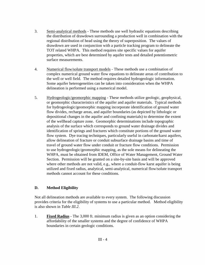
3. Semi-analytical methods - These methods use well hydraulic equations describingthe distribution of drawdown surrounding a production well in combination with theregional distribution of head using the theory of superposition. The values ofdrawdown are used in conjunction with a particle tracking program to delineate theTOT related WHPA. This method requires site specific values for aquiferproperties, which are best determined by aquifer tests and detailed potentiometricsurface measurements.
4. Numerical flow/solute transport models - These methods use a combination ofcomplex numerical ground water flow equations to delineate areas of contribution tothe well or well field. The method requires detailed hydrogeologic information. Some aquifer heterogeneities can be taken into consideration when the WHPAdelineation is performed using a numerical model.
5. Hydrogeologic/geomorphic mapping - These methods utilize geologic, geophysical,or geomorphic characteristics of the aquifer and aquifer materials. Typical methodsfor hydrogeologic/geomorphic mapping incorporate identification of ground waterflow divides, recharge areas, and aquifer boundaries (as depicted by lithologic ordepositional changes in the aquifer and confining materials) to determine the extentof the wellhead capture zone. Geomorphic determinations include topographicanalysis of the surface which corresponds to ground water drainage divides andidentification of springs and fractures which constitute portions of the ground waterflow system. Dye tracing techniques, particularly useful in carbonate/karst aquifers,allow delineation of fracture or conduit subsurface drainage basins and time oftravel of ground water flow under conduit or fracture flow conditions. Permissionto use hydrogeologic/geomorphic mapping, as the sole means for delineating theWHPA, must be obtained from IDEM, Office of Water Management, Ground WaterSection. Permission will be granted on a site-by-site basis and will be approvedwhere other methods are not valid, e.g., where a conduit-flow karst aquifer is beingutilized and fixed radius, analytical, semi-analytical, numerical flow/solute transportmethods cannot account for these conditions.
D. Method Eligibility
Not all delineation methods are available to every system. The following discussionprovides criteria for the eligibility of systems to use a particular method. Method eligibilityis also shown in Table III.2.
1. Fixed Radius - The 3,000 ft. minimum radius is given as an option considering theaffordability of the smaller systems and the degree of confidence of WHPAboundaries in certain geologic conditions.

III - 5
A PWSS may use the Fixed Radius Method after receiving prior approval from theIDEM. Approval to used the Fixed Radius Method is based on the followingcriteria:
a. A PWSS does not qualify as a significant water withdrawal facility(in accordance with IC 13-2-6.1); or
b. A PWSS qualifies as a significant water withdrawal facility, inaccordance with IC 13-2-6.1, and the average daily withdrawal isless than one hundred thousand (100,000) gallons per daydemonstrated by:
• Submittal of annual total pumping data for the previous five(5) years of operation to the department; and
• Statistical determination by the department of an upperconfidence interval of one hundred thousand (100,000)gallons per day or less by the following formula:
_ = t(0.95, n-1)(S/n1/2)
where:_ = Mean of pumping dataS = Standard deviation of pumping datat(0.95,n-1) = t statistic at 95%, n degrees of freedomn = Number of observations
2. Analytical, Semi-analytical and Numerical Flow /Solute TransportThese three methods are available to all PWSSs.
3. Hydrogeologic/Geomorphic Mapping Method - A PWSS may use theHydrogeologic/Geomorphic Mapping Method as the sole method ofdelineation only with prior approval from the department.
III - 6
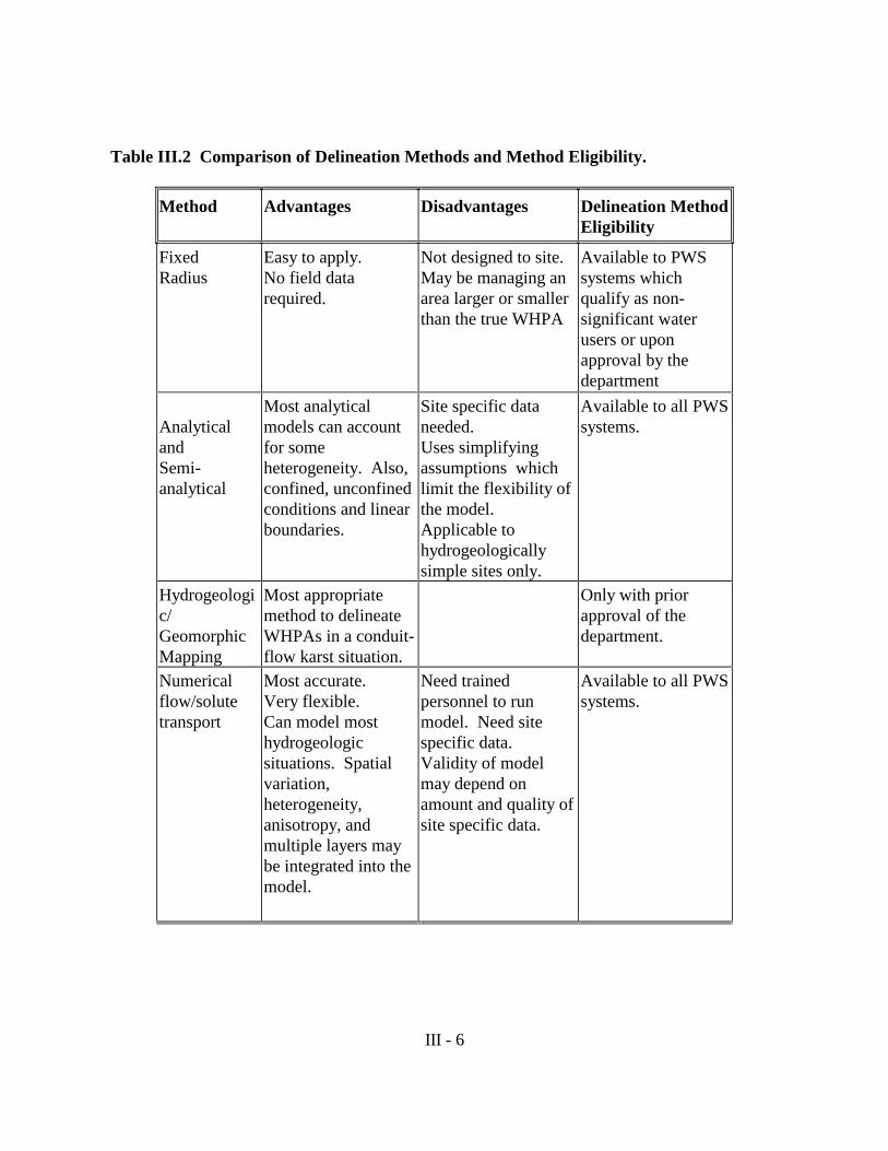
Table III.2 Comparison of Delineation Methods and Method Eligibility.
Method Advantages Disadvantages Delineation MethodEligibility
FixedRadius
Easy to apply.No field datarequired.
Not designed to site.May be managing anarea larger or smallerthan the true WHPA
Available to PWSsystems whichqualify as non-significant waterusers or uponapproval by thedepartment
AnalyticalandSemi-analytical
Most analyticalmodels can accountfor someheterogeneity. Also,confined, unconfinedconditions and linearboundaries.
Site specific dataneeded.Uses simplifyingassumptions whichlimit the flexibility ofthe model. Applicable tohydrogeologicallysimple sites only.
Available to all PWSsystems.
Hydrogeologic/GeomorphicMapping
Most appropriatemethod to delineateWHPAs in a conduit-flow karst situation.
Only with priorapproval of thedepartment.
Numericalflow/solutetransport
Most accurate.Very flexible.Can model mosthydrogeologicsituations. Spatialvariation,heterogeneity,anisotropy, andmultiple layers maybe integrated into themodel.
Need trainedpersonnel to runmodel. Need sitespecific data. Validity of modelmay depend onamount and quality ofsite specific data.
Available to all PWSsystems.

III - 7
E. Choosing a Model
Selecting an appropriate WHPA delineation method requires the consideration of thehydrogeologic setting, WHP management plans, and resources. Choosing a delineationmethod is often a balance between the need for accuracy and the available resources. Thefollowing list are items for consideration in selecting a delineation method. Furtherexplanation of these factors is given in Appendix II, and a comparison of delineationmethods is presented in Figure 4.
1. Hydrogeology
A model simulates site specific ground water flow conditions. Different models cansimulate different hydrogeologic situations, therefore, it is important to choose amodel which can best simulate the flow regime at the site. To best match a model tosite hydrogeological features, the site hydrogeology must first be characterized.
A hydrogeologic characterization essentially gathers and assembles information intoa format for assessment. Information for site characterization includes: 1) type ofaquifer material; 2) hydraulic properties of aquifer; 3) type of aquifer confinement; 4) flow boundaries; and 5) local flow gradients and flow directions. Furtherexplanation of these hydrogeologic properties is found in Appendix II. Informationfor hydrogeologic characterization is found in public domain files (e.g., USGSWater Resources Investigations, Indiana Geological Survey Reports, Masters’ thesis,etc.) and various site-specific data such as test borings, pumping tests, and waterlevel measurements.
Because of the complexity and volume of information gathered, the data should beorganized to be evaluated more readily. This takes the form of cross-sections acrossthe area, various hydrogeologic maps, and tables. These cross sections, maps andtables are also required for submittal to IDEM for review, and are listed in moredetail under submittal requirements within this section.

III - 8
Figure 4

III - 9
2. System Stress and Management Plans
When choosing a delineation method, consideration should also be given to: 1)current and anticipated size of system; 2) WHP goals and management strategies; 3) defensibility of chosen method; 4) well field geometry; and 5) nearby pumpingcenters.
3. Resources
For many PWSSs a major consideration in the selection of a delineation method isthe availability of resources, including equipment, technical expertise, and monetaryresources. It is important that the person(s) conducting the WHPA delineation havea thorough knowledge of hydrogeology. Site characterization and WHPAdelineation, using analytical, semi-analytical, numerical flow/solute transport orhydrogeologic/geomorphic mapping methods, must be performed by a qualifiedground water scientist. Since equipment or technical expertise may be obtained byhiring a consultant, the ability to delineate using the most desirable method mayultimately depend on available budget. Recognizing the need to budget and thelimitations of smaller systems, the time for Phase 1 submittal is varied, dependingon the size of the system (See Table I.1). The intent of the variable time frame is toallow the PWSS to consider both the type of delineation they desire and to allowadequate time to budget for the delineation.
With an understanding of method eligibility, site-specific hydrogeology, and managementplans, a WHPA delineation method can be selected that best balances the level of accuracyrequired with available resources.
It may cost a community more to delineate using an analytical model than thefixed radius method. However, for a system pumping from a aquifer withlow transmissivity, the fixed radius method will probably contain areas thathave no effect on the water supply based on time of travel. An analyticalmodel would provide a more accurate delineation of the area that needs to beprotected, have greater defensibility and ensure a greater degree ofconfidence to the community.
III - 10
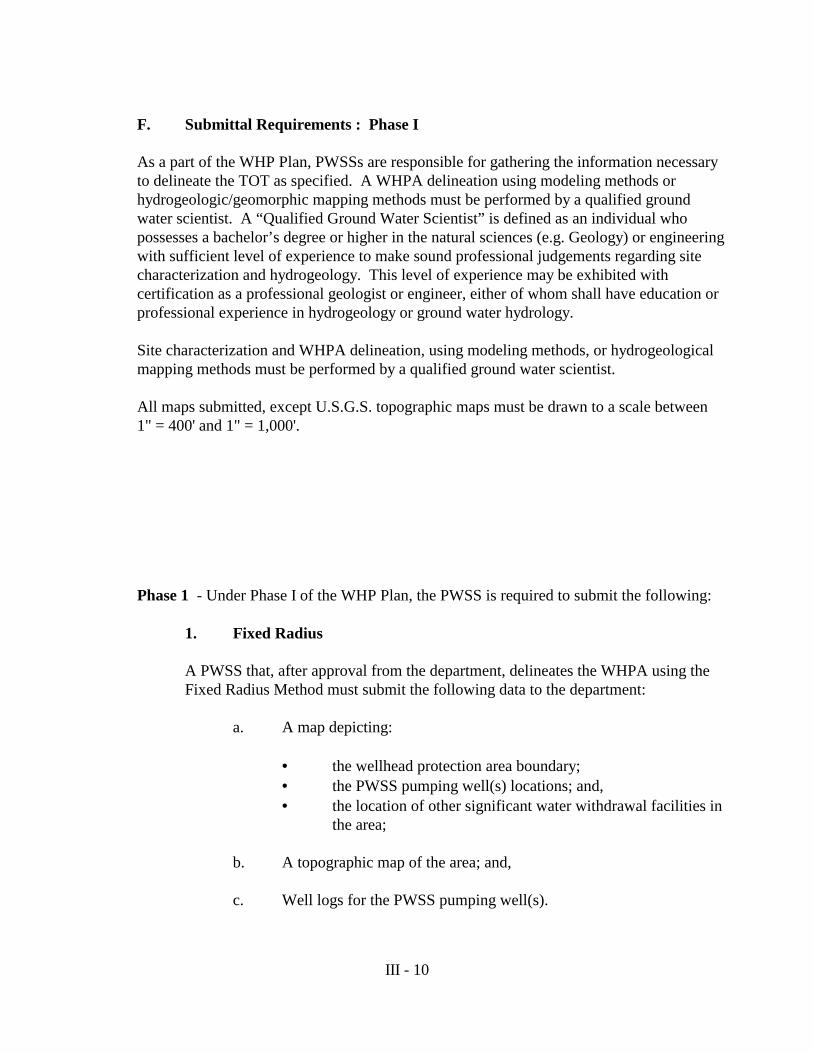
F. Submittal Requirements : Phase I
As a part of the WHP Plan, PWSSs are responsible for gathering the information necessaryto delineate the TOT as specified. A WHPA delineation using modeling methods orhydrogeologic/geomorphic mapping methods must be performed by a qualified groundwater scientist. A “Qualified Ground Water Scientist” is defined as an individual whopossesses a bachelor’s degree or higher in the natural sciences (e.g. Geology) or engineeringwith sufficient level of experience to make sound professional judgements regarding sitecharacterization and hydrogeology. This level of experience may be exhibited withcertification as a professional geologist or engineer, either of whom shall have education orprofessional experience in hydrogeology or ground water hydrology.
Site characterization and WHPA delineation, using modeling methods, or hydrogeologicalmapping methods must be performed by a qualified ground water scientist. All maps submitted, except U.S.G.S. topographic maps must be drawn to a scale between 1" = 400' and 1" = 1,000'.
Phase 1 - Under Phase I of the WHP Plan, the PWSS is required to submit the following:
1. Fixed Radius
A PWSS that, after approval from the department, delineates the WHPA using theFixed Radius Method must submit the following data to the department:
a. A map depicting:
• the wellhead protection area boundary;• the PWSS pumping well(s) locations; and,• the location of other significant water withdrawal facilities in
the area;
b. A topographic map of the area; and,
c. Well logs for the PWSS pumping well(s).

III - 11
2. Analytical, Semi-Analytical or Numerical Flow/Solute Transport
When a PWSS delineates the WHPA using an analytical, semi-analytical ornumerical flow/solute transport model, a report with a narrative description of theregional hydrogeologic setting, the conceptual model, and modeling efforts must besubmitted. The report must include the following:
a. An analysis of the hydrogeologic setting and the conceptual modelincluding:
• Map of the area of interest;
• Review of published hydrogeologic and geologicinterpretations over the area of interest;
• Geologic cross sections1 showing:- hydrostratigraphic units;- water levels;- relationship of surface water bodies to the
hydrostratigraphic units; and- pumping wells with screened intervals;
• Well logs and records used in cross-section development;
1 Must be performed by or under the supervision of a Certified Professional Geologist and bear his/her seal or be performed by
a) an officer or employee of the federal, state or local goverment while engaged in providing geological services for theofficer’s or employee’s employers, b) a person engaged solely in geological research or instruction of geology, c) aprofessional engineer registered under IC 25-31 who applies geology to the practice of engineering.
• Map(s) which illustrate over the area of interest:- location of PWSS wells;- other high capacity wells in the area;- surface water features located within the area of
interest;- thickness and extent of hydrostratigraphic units1;
III - 12
- regional water levels; and- bedrock topography1;
• Summary of raw data used in the development of theconceptual model;
• Discussion of hydrogeologic parameters;
• Discussion of the ground water flow system including:- distribution of recharge;- current PWSS pumping rates and planned changes in
pumping rate; and,- pumping rates of neighboring high capacity wells;
b. Presentation and discussion of the modeling effort must include:
• The rationale for delineation method selection;
• A tabulated summary of the model input parameters showingthe range over which the parameters were varied;
• An example input file;
__________________
1 Must be performed by or under the supervision of a Certified Professional Geologist and bear his/her seal or be performed by a) an officeror employee of the federal, state or local goverment while engaged in providing geological services for the officer’s or employee’semployers, b) a person engaged solely in geological research or instruction of geology ,c) a professional engineer registered under IC 25-31who applies geology to the practice of engineering.
. • Map(s) showing:- the domain of the modeled area within the area of
interest;- location of any boundary conditions used;- calibration target locations, if used;- modeled potentiometric surfaces; and- resultant WHPA boundaries;

III - 13
• A discussion of :- assumptions used in the modeling effort;- changes made to initial conditions;- calibration analysis if used;- water budget of the model, if available; and- effects of uncertainity in input parameters and
boundary conditions on modeled WHPA boundaries.
3. Hydrogeologic/Geomorphic Mapping Method
A PWSS that delineates the WHPA using the Hydrogeologic/Geomorphic MappingMethod must submit data as required and agreed to by the IDEM and the PWSS.
Phase II
Following Phase I approval of the WHP plan, the PWSS will have 5-10 years (See TableI.1) to submit Phase II of the WHP plan for final approval. Phase II submittal requirementsconcerning WHPA delineation include:
1. An updated Phase I submittal reflecting changes, if any; and
2. A discussion describing how the updated WHPA compares with thepreviously delineated WHPA.
Due to seasonal water level data collected during the interim between Phase I and Phase II, theupdated WHPA may differ from the initially delineated WHPA. In this situation, the PWSSswill be required to combine both initial and updated WHPAs to define their final WHPA forWHPP approval by IDEM. However, if, based on better non-transient data, the WHPAdelineation is better defined in Phase II the newly defined WHPA would be submitted toIDEM.
G. IDEM Review Criteria
Review of submitted wellhead protection programs will be performed by the IDEM’s DrinkingWater Branch. The WHPA review criteria was developed, in part, by a subcommittee of theWellhead Workgroup. The subcommittee included representation from the USGS, IGS, IDNR,IDEM, industry, environmental groups and consulting firms.
III - 14
1. Review Criteria for Fixed Radius Method
In reviewing a WHPA which has used a fixed radius method, the IDEM willdetermine if the PWSS has hydraulic parameters which fall above or below theaverage parameters (determined by review of published reports). For example, isthe transmissivity for the area of the PWSS much greater than 20,000 ft2/d, the valueused to model the 3,000 ft. radius? To determine these hydrogeologic parametervalues, IDEM may examine or use tools such as:
• The pumping history of the PWSS ;• Published reports of the area in which the PWSS is located;• Unpublished reports and files held at IDEM; and,• Analytical or semi-analytical modeling.
2. Review Criteria for Analytical, Semi-Analytical, Numerical Flow/SoluteTransport and Hydrogeologic/Geomorphic Mapping Method
Under Indiana’s WHPP, delineations submitted to the IDEM will be reviewedaccording to the following general criteria:
• The completeness and accuracy of the data used to determine thehydrogeologic conceptualization; and
• The information submitted demonstrates that the chosen delineationmethod properly accounts for site specific hydrogeology.
After review, the IDEM may require additional data to be submitted. Additionaldata may be required when further information is needed to support justifications ofdelineation method or to verify assumptions used in modeling.
Based on the hydrogeologic setting, the IDEM may require the PWSS to use adifferent method to delineate the WHPA (e.g., a PWSS withdrawing water from aconduit-flow karst aquifer ). Analytical, semi-analytical and numerical models, aswell as the fixed radius approach, may not be appropriate for delineation of aWHPA in a karst aquifer. Based on site specific information, systems which exhibitconduit-flow regimes must propose an appropriate delineation methodology for theapproval by the IDEM, such as dye tracing or basin analysis (paleo-topographicanalysis).
H. Relationship between Delineation and Source I.D./Management
As previously stated, the purpose of delineating the WHPA is to identify a wellfield
III - 15
management area within the area of contribution. In considering management options,delineation of a WHPA allows the PWSS and the community to consider where the groundwater comes from and an estimate of how long the ground water takes to reach the wellsystem from a particular area. With this information, the PWSS and the community arebetter equipped to protect their water supply from contamination. Management of theWHPA will vary with management strategy but, in general, the WHPA outlines the areawhere source inventories are performed, owners/operators of potential contaminant sourcesare educated, best management practices are adopted, public education is performed, andzoning regulations, if used, are implemented.

IV. Identification and Inventory of Potential Sources of Contamination
A. Purpose of Source Identification................IV-1
B. Submittal Requirements.............................IV-4
C. IDEM Review Criteria...............................IV-5
D. On-going Activities...................................IV-5

IV-1
IV. IDENTIFICATION AND INVENTORY OF POTENTIAL SOURCES OFCONTAMINATION
A. Purpose of Source Identification
An inventory of potential sources of contamination or source identification (ID.) providesan opportunity to identify any past, present, and proposed activities that may pose a threat tothe well(s) or well field. This includes any new activities and changes in the operationalstatus of previously inventoried facilities. Maintaining an accurate and complete inventoryof potential sources of contamination is of the utmost importance to safeguarding acommunity’s drinking water and an essential part of the Wellhead Protection plan.
Indiana’s WHPP requires community public water supply systems (PWSSs) to complete aninventory of all potential sources of contamination (including those sources controlledthrough regulatory approaches and unregulated sources such as non-point sources) withinthe wellhead protection area (WHPA). The PWSS is encouraged to begin the initial sourceidentification and inventory process in the early stages of WHP planning. The source andinventory aids in developing an appropriate management strategy for the community’scircumstances. Once the potential sources of contamination are known, options to eliminateor manage the contamination threat can be considered.
To assist PWSSs in the identification of the types of activities to consider, Table IV.1 listsvarious types of ground water contamination and Table IV.2 lists various inventoryprocedures; a combination of these tools will be required to conduct a complete inventory. More specific guidelines for source ID. will be provided in a technical assistance documentfocussed on the inventory and management of potential sources of contamination.
A potential source of contamination may pose a threat to the ground water for a variety ofreasons. Some reasons are intrinsic to the substance such as toxicity and mobility. Physicalfactors , which can increase the risk of contamination to ground water, include concentrationand volume of substances stored, proximity to water supply wells, operational procedures,maintenance, closure status, the design and age of facility, and local hydrogeologicvulnerability.

IV-2
TABLE IV.1 POTENTIAL CONTAMINANT SOURCES (listed alphabetically)
AGRICULTURAL
Animal burial areasAnimal feedlotsChemical application (e.g., pesticides, and fertilizers)Chemical storage areasIrrigationManure spreading and pits
COMMERCIAL
AirportsAuto repair shopsBoat yardsConstruction areasCar washesCemeteriesDry cleaning establishmentsEducational institutions (e.g., labs, lawns, and chemical storage areas)Gas stationsGolf courses (chemical application)Jewelry and metal platingLaundromatsMedical institutionsPaint shopsPhotography establishments/printersRailroad tracks and yards/maintenanceResearch laboratories
Road deicing operations (e.g., road salt)Road maintenance depotsScrap and junkyardsStorage tanks and pipes (above- ground, below-ground, underground)
INDUSTRIAL
Asphalt plantsChemical manufacture, warehousing, and distribution activitiesElectrical and electronic products and manufacturingElectroplating and metal fabricationFoundriesMachine and metalworking shopsManufacturing and distribution sites for cleaning suppliesMining (surface and underground) and mine drainagePetroleum products production, storage, and distribution centersPipelines (e.g., oil, gas, coal slurry)Septage lagoons and sludgeStorage tanks (above-ground, below-ground, underground)Toxic and hazardous spillsWells - operating and abandoned (e.g., oil, gas, water supply, injection, monitoring and exploration)Wood preserving facilities
RESIDENTIAL
Fuel storage systemsFurniture and wood strippers and refinishersHousehold hazardous productsHousehold lawns (chemical application)Septic systems, cesspools, water softenersSewer linesSwimming pools (e.g. chlorine)
WASTE MANAGEMENT
Fire training facilitiesHazardous waste management units (e.g, landfills, land treatment areas, surface impoundments, waste piles, incinerators, treatment tanks)Municipal incineratorsMunicipal landfillsMunicipal wastewater and sewer linesOpen burning sitesRecycling and reduction facilitiesStormwater drains, retention basins, transfer stations
Source: United States Environmental Protection Agency. 1989Wellhead Protection Programs: Tools for Local Governments. EPA 440/6-89-002

IV-3
TABLE IV.2 Recommended Inventory Procedures
Method Consists of: Outcome Required orRecommended
Outreach ProgramsPublic meetings, workshops,brochures, public serviceannouncements, andnewsletters
Gain local supportand cooperation forWHP.
Recommended
Windshield Surveys Drive through WHPA andlocate/verify businesses andland use practices which couldbe a potential source ofcontamination.
Familiarize staffwith WHPA andverify base map
Recommended
Site Inspections Inspections of facilities Very useful inobtainingadditionalinformation onpotential sources ofcontamination.
Recommended
Records Review
Search of public records (e.g.;State Databases)
· Remedial status of RCRA, Superfund or State Clean-up Sites.· UST Files· Emergency Response-Spills· Sara Title III· Hazardous waste handler· Zoning maps· Property ownership maps· Fire-insurance maps, etc.
Useful in obtaininginformation onpotential sources ofcontamination bothpast and present
Required
IV-4
B. Submittal Requirements
Source ID. submittal requirements for the program are as follows:
1. Phase I
An inventory of all potential sources of contamination consisting of a completelist of existing facilities, sites, practices, and activities for both regulated andunregulated . Source information should be compiled into a format which is easyto access and update by the PWSS. A recommended format for source inventorycan be found in Table IV-3. The inventory of sources identified shall besubmitted in the following forms:
a. A narrative description of land use within the wellhead protectionarea (WHPA);
b. A map with potential sources of contamination plotted, showingtheir locations, and an inventory of land use (i.e., zoning,distribution, agriculture areas, etc.);
c. A table containing information describing the potential sources of contamination including:
• An identification number (cross-referenced to the map withlocations of potential sources of contamination);
• Facility name and location;• Site description (which may include facility history (how
long the facility has been operating), how long the type ofchemical(s) or structure(s) listed have been used, previouspractices at the site, etc.);
• Any environmental permits issued for the site, includingnumber and agency issuing the permit; and
• Operating status of site (i.e., remedial status, closure,corrective action, etc.).
2. Phase II
a. A Phase II source ID. updating the source inventory provided inthe Phase I submittal.
b. A comment summary, reporting problems or concerns regardingthe WHP plan and the source inventory.

IV-5
C. IDEM Review Criteria
IDEM shall review Phase I and Phase II submittals based on the following criteria:
1. The completeness of the specific data supplied regarding the facility, site,practice, and activity, including:
• The inventory, permit or identification number and location of allpotential sources of contamination;
• Identification of all potential sources of contamination in theWHPA on a map (scale of 1"= 400’ and 1"=1,000’) which includesthe boundaries of the time of travel; and
• The characterization of potential sources is sufficient to develop amanagement plan .
2. IDEM will evaluate Phase II based on the completeness of the update toadequately characterize the status of all potential sources of contaminationidentified and inventoried under Phase I, and any new potential sources ofcontamination that have located within the WHPA.
3. IDEM will evaluate the updates made to the potential sources ofcontamination inventory every five (5) years, as required, for completenesswith respect to the status of all potential sources of contaminationidentified in the Phase I and Phase II submittals.
D. On-going Activities
The PWSS will track the status of potential sources within their WHPA accordingto the following:
1. The location of new sources established in the WHPA;
2. Closure of existing sources; and
3. Continual update of the source ID. inventory.
This information will be supplied in status reports which will be submitted toIDEM on a five (5) year, continual basis.

IV-6
Table IV.3 - Example Reporting Format for Potential Source Inventories
I.D.Nu
mber
FacilityName
andLocation
Site Description PermitNumber
and Type
Type ofContaminants
Operating
Status
93020
Bob’sGas-Mart
120 S.12th St.
UST’s (3) U-32-91-IN
BETX, MTBE,Gasoline, etc.
Operating
Class V Well(garage bay)
N/A Solvents, oil Operating
93056
EZ-Chem
3245 N.Hammer
Chemical Storage R-19-80-IN
VOC’s, PCB’s Closed
9/14/92
93015
Steve’sCleaners
15 So.9th Ave.
Dry Cleaners N/A PCE Operating
93037
1st StreetDump
1501 S.1st St.
Solid WasteLandfill
S-37-93-IN
Municipal Waste,VOC’s, SVOC’s,Possible PCB’s
Operating
93057
StateRoad 99(Mile numbers 34,36, 45, 51, 63, &77)
Storm waterdrainage wells(6) N/A
Highway runoff(e.g., metals,VOC’s, petroleum,solvents, etc.)
Operating
93030
Stop-N-Fuel 3456 N. 18th St.
UST’s (6)**LUST site**
U-99-89-IN
L-03-93-IN
BETX, MTBE,Styrene
Closed, under
LUST Clean-up
93006
Johnson’sFarm
RR 3201SR 66
(990 acres)
Farm fields,Confined animalfeeding lots,pesticide storage
LA-32-86-IN
Pesticides,animal wastes(nitrates,phosphorus, etc.)
Operating
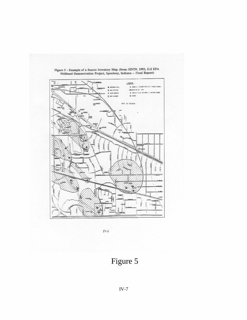
IV-7
Figure 5

V. Management Approaches of WellheadProtection Areas
A. Management Objectives...............................................V-1
B. Management Areas.......................................................V-3
C. Management Submittal Requirements..........................V-3
D. Management Strategy and Review Criteria..................V-5
E. WHPP Outreach Review .............................................V-6
F. Coordination of State and Local Authorities................V-7
G. IDEM Management Plan Tracking...............................V-8
V-1
V. MANAGEMENT APPROACHES OF WELLHEAD PROTECTION AREAS
The protection of public water supply systems (PWSSs) from contamination is primarily basedon the appropriate management of potential sources of contamination within the wellheadprotection area (WHPA). In this, a major component of a PWSS’s local Wellhead Protectionplan will be the development and implementation of a management strategy (Phase I). Under theIndiana WHPP, PWSSs will be required to develop a management strategy which outlines theactions the PWSS will initiate to manage specific potential sources of contamination in order toprotect the quality of the ground water in the WHPA. The degree of protection provided shouldbe based on the types of potential sources located in the WHPA and the degree of risk posed bythe source determined by the proximity to the well field, hydrogeologic sensitivity and type ofactivity. The management strategy should build on existing regulatory control programs at alllevels of government. Education of owners/operators of potential contaminant sources, andvoluntary adoption of best management practices (BMPs) by a given facility, are important firststeps in implementing protective measures.
Phase II will consist of updates and implementation of the plan. In that, Phase II will serve todocument that the activities proposed under the management strategy (Phase I) are beingimplemented. The plan will be evaluated every five years, as potential source management is anon-going process.
A. Management Objectives
PWSSs are expected to develop a comprehensive and coordinated management strategyon the basis of the following objectives:
1. Education Program
The management plan must include a public outreach program to educate thepublic and owners/operators of identified sources of contamination about theconsequences of ground water contamination, and the methods available forpreventing ground water contamination.
2. Existing Source Management Plan
The plan must include policies and procedures for protecting all water supplywells from identified potential sources of contamination within the WHPA. Forexample, potential sources could be encouraged to incorporate
V-2
waste minimization, involving some or all of the following2:
2 Further detail on pollution prevention, source reduction, and waste minimization activities
for source management will be incorporated in a future source identification/managementtechnical document.
· Source reduction;· Good housekeeping practices that reduce spill potential;· Input material modification and product substitution;· Technology changes and process modifications;· Separation of hazardous and nonhazardous waste;· Recycling, reclamation, and reuse; and· Treatment to reduce toxicity of hazardous substances.
3. New Source Management Plan
The plan must include specific measures planned to protect all water supply wellswithin the WHPA from potential new sources of contamination.
4. Transportation Routes Management Plan
The management plan must include policies describing how the transportationroutes will be managed in order to minimize ground water pollution throughaccidental spills, leakage etc.
5. Future Management Plan
The WHPA management plan must consider how the current plan will adjust tofuture situations associated with growth.
Each water supply, whether publicly or privately owned, is responsible for selecting anddeveloping a series of management approaches best suited to the task of controllingpotential sources of contamination within its WHPA. The process of developing
V-3
management approaches should consider all pros and cons to wellhead protection (WHP)to facilitate selection of the best approach. Management plans should be site specific intheir approach. Land use, potential sources of contamination, community characteristics,and the availability of funds and assistance are some factors to be considered.
B. Management Areas
There are two (2) management areas that need to be protected under the State’s WHPP,these two areas are described as follows:
Sanitary Setback -- This is the setback area required to protect ground waterfrom microbial contamination. In unconfined aquifers it is a 200-foot radiusaround the well and for confined aquifers it is a 100-foot radius around the well. These radii may be increased due to the site specific geologic environment.
WHPA -- WHPA (chemical response area) is the land surface area within, at aminimum, a five (5) year time of travel (TOT) area or within 3,000 feet from thewell(s). The PWSS is required to formulate a management strategy for allpollution sources of contamination within this area. All identified sources ofcontamination are expected to comply with applicable State constructionstandards and permit requirements.
C. Management Submittal Requirements
As a portion of the overall, local wellhead protection program, all community PWSSs must initially develop a strategy for the management of all potential sources ofcontamination identified in the WHPA (Phase I). In addition, the PWSS must implementthe strategy developed under Phase I and document where those measures have beencompleted or are underway (Phase II). All WHP management strategies must meet theminimum management requirements outlined below; however, these requirements do notprohibit a PWSS or community from instituting more stringent requirements.
Phase I
1. Sanitary Setback Area (100 or 200-foot radius)
Each community PWSS must develop a plan which describes the measuresthey will undertake to manage the Sanitary Setback area. The plan of

V-4
proposed measures must be consistent with the following requirements:
a. This area must be managed by the PWSS consistent with therequirements for sanitary setbacks in the well construction permit.(327 IAC 8-3).
b. Prohibit the storage or mixing of chemicals other than thefollowing:
• those used for drinking water treatment, or• pesticides which are regulated by Indiana Pesticide Review
Board through IC 15-3-3.5 and IC 15-3-3.6.
c. Secure the wellhead(s) to prevent unauthorized access (e.g., afence or building).
d. Provide appropriate management of existing roads within thesanitary setback (i.e., curbs, gutters, linings, etc.).
2. WHPA
Each community PWSS is required to develop a strategy proposing themeasures the system (and/or community) will undertake to managepotential sources of contamination within the WHPA which addresses thefollowing:
a. Proposed management or monitoring measures for all potentialsources of contamination, as identified by the potential sourceinventory. The management or monitoring measures mustconsider the location and type of potential pollution source, aswell as the hydrogeologic characteristics of the WHPA.
b. Compliance of PWSS production wells with state constructionstandards and permit requirements under 327 IAC 8-3 and 310IAC 16.
c. Monitoring for contaminants associated with identified potentialsources of contamination according to the IDEM’s standardizedmonitoring framework under 327 IAC 8-2.
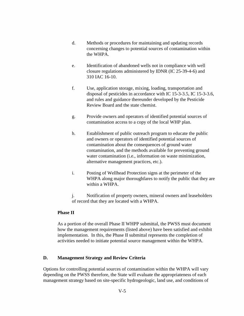
V-5
d. Methods or procedures for maintaining and updating recordsconcerning changes to potential sources of contamination withinthe WHPA.
e. Identification of abandoned wells not in compliance with wellclosure regulations administered by IDNR (IC 25-39-4-6) and310 IAC 16-10.
f. Use, application storage, mixing, loading, transportation anddisposal of pesticides in accordance with IC 15-3-3.5, IC 15-3-3.6,and rules and guidance thereunder developed by the PesticideReview Board and the state chemist.
g. Provide owners and operators of identified potential sources ofcontamination access to a copy of the local WHP plan.
h. Establishment of public outreach program to educate the publicand owners or operators of identified potential sources ofcontamination about the consequences of ground watercontamination, and the methods available for preventing groundwater contamination (i.e., information on waste minimization,alternative management practices, etc.).
i. Posting of Wellhead Protection signs at the perimeter of theWHPA along major thoroughfares to notify the public that they arewithin a WHPA.
j. Notification of property owners, mineral owners and leaseholders of record that they are located with a WHPA.
Phase II
As a portion of the overall Phase II WHPP submittal, the PWSS must documenthow the management requirements (listed above) have been satisfied and exhibit implementation. In this, the Phase II submittal represents the completion ofactivities needed to initiate potential source management within the WHPA.
D. Management Strategy and Review Criteria
Options for controlling potential sources of contamination within the WHPA will varydepending on the PWSS therefore, the State will evaluate the appropriateness of eachmanagement strategy based on site-specific hydrogeologic, land use, and conditions of

V-6
potential sources of contamination.
The State of Indiana will consider a management strategy to be effective when:
1. The plan has local management initiatives to prevent contamination fromexisting, as well as future, potential sources of contamination.
2. The plan fully describes the policies and procedures for protecting allexisting and proposed new water supply wells.
3. The plan considers the locations and types of sources, as well as the hydrogeologic nature of the WHPA in the selection of management
approaches.
4. The plan outlines a strategy to educate the public about the consequencesof ground water contamination and the methods available to preventground water contamination.
E. WHPP Outreach Program
Education of the public is an important part of the management program and a necessarytool in building support in the community for the local WHP plan. Hence, publicawareness and understanding of the need for WHP must be promoted. The PWSS, withthe cooperation of the local government, will have the ultimate responsibility of educatingthe local community about the consequences of ground water contamination and themethods available to prevent ground water contamination.
IDEM will initiate a public outreach effort in two parts; Part one will deal with theunderstanding of a proper management strategy, and Part two will address theimplementation of the management strategy.
Part 1
The public will be educated about what a proper management strategy meansunder the State’s WHPP and why it is necessary to have a comprehensivemanagement strategy. The target audiences will be PWSS owners and operators, community leaders, business leaders and the general public. The IDEM will alsoinvolve professional organizations, such as Indiana Water and WastewaterAssociation, Indiana Environmental Health Association, Indiana Association ofCities and Towns, Indiana Rural Water Association, American Water Works

V-7
Association, etc., during this phase of the outreach program.
Part 2
The outreach program, during Part 2, will focus more on the details of specificmanagement practices, public education, and the implementation of specificmanagement goals. The IDEM will provide resources for technical/educationalassistance to individual community members and also to those associated withPWSSs. Bulletins, pamphlets and fact sheets, which describe Indiana’s WHPP,will be prepared and distributed to PWSS owners and operators, communityleaders, business leaders and the general public. Representatives from the IDEMwill organize and participate in local workshops to facilitate networking and thesharing of information. Seminars will be arranged to make presentations on thetechnical aspects of the program. Meetings will be scheduled so the generalpublic is able to communicate to the IDEM types of local problems encounteredduring implementation of the program.
Public involvement and public education can also be accomplished through publichearings, technical advisory groups, newsletters, brochures and public serviceannouncements. Communication promotes public trust and confidence and is avital part of the WHPP.
F. Coordination of State and Local Authorities
The development, and subsequent implementation, of the WHPP is a coordinated effortby a number of local, State and federal agencies, with the IDEM assuming the leadershiprole. The WHPP will affect other program areas by influencing decisions such asremedial priorities, facility siting decisions, and design criteria for ground waterprotection, etc.
All existing State programs including pollution prevention, emergency response, StateCleanup, Superfund sites, etc., will be notified of approved local WHP plans. Wherepotential contaminant sources identified in the WHPA are regulated by a State program,the appropriate program will prioritize permit, compliance and enforcement actions forthose sources. The Ground Water Section is working with existing State programs toensure consistency among those who will be affected by a local WHP plan.
The management of a WHPA which extends over political boundaries, such as a countyline, must be given equal priority. A high level of coordination between affected localgovernments should be undertaken. Neighboring local governments will have theresponsibility to extend full cooperation to the concerned PWSS to implement an

V-8
effective management strategy. The IDEM will take part in coordination between theparties in such situations.
The area of the WHPA extending into adjacent states will be required to meet the WHPrequirements of the adjacent State. The IDEM will participate and facilitate thecoordination of relevant authorities in inter-State issues.
In general, the State will have the following responsibilities concerningmanagement of the WHPA:
1. Provide source information data for regulated facilities.
2. Provide adequate management of regulated facilities consistent withdesign, siting, and enforcement requirements as outlined in Stateregulations.
3. Provide geologic Information (where available):
a. Well logs;b. Hydrogeologic properties of aquifer(s); andc. Climatic data.
4. Provide spill response information.
5. Provide technical/educational assistance:
a. Documents (e.g., source identification and management);b. Examples of ordinances/zoning; and c. Mediate negotiations between multi-jurisdictional authorities.
G. IDEM Management Plan Tracking
The IDEM will be tracking approved local plans and implementation of local management strategies. Continued tracking of management plans will begin five (5) years after t
of specific sites on the basis of source inventory and by information provided byindividuals. Where a problem is identified, an inspector may visit the site.
The IDEM will track Phase I accomplishments by mailing two (2) surveys to each PWSS
• For large PWS systems, the first survey will be mailed two (2)years, and the second will be mailed one (1) year, prior to the
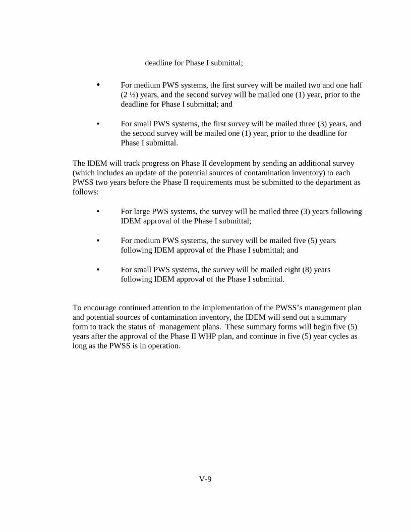
V-9
deadline for Phase I submittal;
• For medium PWS systems, the first survey will be mailed two and one half(2 ½) years, and the second survey will be mailed one (1) year, prior to thedeadline for Phase I submittal; and
• For small PWS systems, the first survey will be mailed three (3) years, andthe second survey will be mailed one (1) year, prior to the deadline forPhase I submittal.
The IDEM will track progress on Phase II development by sending an additional survey(which includes an update of the potential sources of contamination inventory) to eachPWSS two years before the Phase II requirements must be submitted to the department asfollows:
• For large PWS systems, the survey will be mailed three (3) years followingIDEM approval of the Phase I submittal;
• For medium PWS systems, the survey will be mailed five (5) yearsfollowing IDEM approval of the Phase I submittal; and
• For small PWS systems, the survey will be mailed eight (8) yearsfollowing IDEM approval of the Phase I submittal.
To encourage continued attention to the implementation of the PWSS’s management planand potential sources of contamination inventory, the IDEM will send out a summaryform to track the status of management plans. These summary forms will begin five (5)years after the approval of the Phase II WHP plan, and continue in five (5) year cycles aslong as the PWSS is in operation.
VI. WHPP Contingency Plans
A. Phase I Submittal Requirements.........................VI-1
B. Phase II...............................................................VI-2
C. IDEM Responsibilities........................................VI-2

VI-1
VI. WHPP CONTINGENCY PLANS
A contingency plan is the most effective way of protecting the community from possible hazardousconditions involving a water supply and helps avoid possible confusion during an emergencysituation. A contingency plan should outline response procedures in the event of water supplydisruption due to contamination from spills or floods. As a part of the Indiana Wellhead ProtectionProgram (WHPP), all community public water supply systems (PWSSs) must submit the minimumrequirements of a complete contingency plan (as described in this section) to the IDEM forapproval.
SARA Title III and the Federal SDWA require each State to coordinate with community PWSSs inthe development of contingency plans for emergencies. In Indiana, coordination of PWSScontingency plans is through the Office of Water Management, Drinking Water Branch. Throughthese federal and State authorities, each PWSS is required to have a contingency plan in place todescribe procedures in response to emergencies.
Under Indiana’s WHPP, a section of the contingency plan is required to focus on response tocontamination. However, if the PWSS has not developed a comprehensive contingency plan as apart of the system’s WHP plan, a contingency plan for contamination events is required to bedeveloped. If a contingency plan is in place, the following items must be included and submitted inthe plan.
A. Phase I Submittal Requirements
Under the Indiana Wellhead Protection program, all PWSSs are required to prepare,maintain, and post procedures to follow in a contamination emergency and information onthe location and availability of the complete contingency plan. Contents of the contingencyplan submittal for Phase I must include the following:
1. A description of the system’s plan to train local responders3 about theirresponsibilities in an emergency situation within a Wellhead Protection Area(WHPA). Minimum instructions to responders must include the following:
a. location of WHPA boundaries;b. community members to contact in case of emergencies; andc. PWSS operators to contact during an emergency.
3 Examples of the local responders who should receive the training described include local fire
departments, hazmat teams, and police.
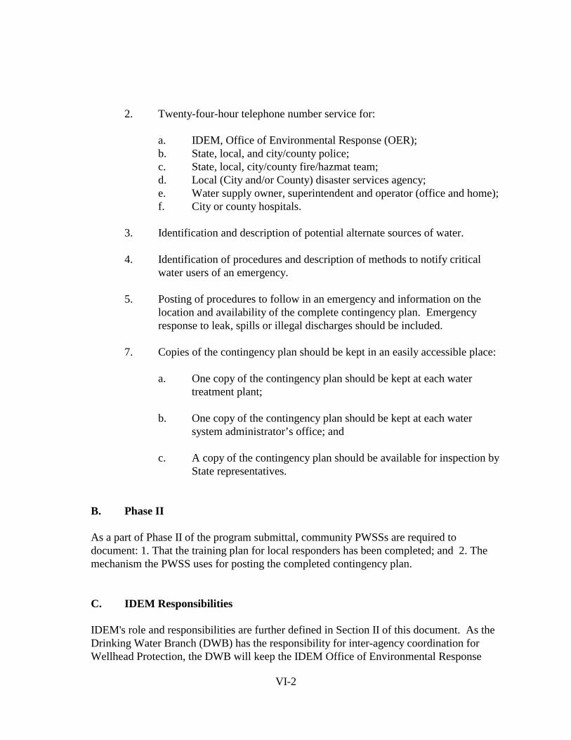
VI-2
2. Twenty-four-hour telephone number service for:
a. IDEM, Office of Environmental Response (OER);b. State, local, and city/county police;c. State, local, city/county fire/hazmat team;d. Local (City and/or County) disaster services agency;e. Water supply owner, superintendent and operator (office and home);f. City or county hospitals.
3. Identification and description of potential alternate sources of water.
4. Identification of procedures and description of methods to notify criticalwater users of an emergency.
5. Posting of procedures to follow in an emergency and information on thelocation and availability of the complete contingency plan. Emergencyresponse to leak, spills or illegal discharges should be included.
7. Copies of the contingency plan should be kept in an easily accessible place:
a. One copy of the contingency plan should be kept at each watertreatment plant;
b. One copy of the contingency plan should be kept at each watersystem administrator’s office; and
c. A copy of the contingency plan should be available for inspection byState representatives.
B. Phase II
As a part of Phase II of the program submittal, community PWSSs are required todocument: 1. That the training plan for local responders has been completed; and 2. The mechanism the PWSS uses for posting the completed contingency plan.
C. IDEM Responsibilities
IDEM's role and responsibilities are further defined in Section II of this document. As theDrinking Water Branch (DWB) has the responsibility for inter-agency coordination forWellhead Protection, the DWB will keep the IDEM Office of Environmental Response

VI-3
(OER) informed of approved WHPA boundaries throughout the State and emergencycontacts for the PWSS system. In cases where OER responds to emergencies within aWHPA, OER will be requested to notify the emergency contact for the system and providethe DWB with a summary of the response actions which occurred in the WHPA as a resultof the contamination emergency.

VII. NEW WELLS
A. New Well Site Scenarios.......................................VII-1
B. New Well Site Submittal Requirements.................VII-2
C. Conditions of Well Site Approval ........................VII-4

VII-1
VII. NEW WELLS
The federal Safe Drinking Water Act (SDWA) requires that each State’s wellhead protectionprogram (WHPP) include a description of the process for siting and managing new public watersupply system (PWSS) wells. To this end, Indiana is incorporating wellhead protection in theapproval process of new wells and well fields to help insure proper siting. Indiana’s new wellsiting process will include preliminary WHPA delineation and source identification in the siting fornew wells. The revised well site approval procedures will be incorporated into the wellheadprotection regulations as a requirement for all new well field development.
A. New Well Site Scenarios
In general there are two types of situations that require approval, these are: 1) a new well isgoing into an existing well field, and 2) a new well site is being developed.
1. New Well in Existing Well field
In an existing well field, a well may: (a) be located in an IDEM approved Phase I orPhase II WHP plan and the new well was included in the WHPA delineation; (b) belocated in an IDEM approved Phase I WHP plan and the proposed new well is in theexisting well field but was not included in the WHPA delineation of the well fieldand; (c) the well field is not included in an IDEM approved Phase I or Phase IIWHPP.
a. The PWSS has an approved Phase I WHP plan and the new well wasincluded in the initial WHPA delineation either in the well placementor the pumping capacity of the well field. For these situations, theproposed new well already possesses an approved well site due to theapproval of the Phase I WHP plan (i.e., well site review area isdelineated and the source inventory performed). The PWSS isrequired to apply for a construction permit (following the guidelinesin 327 IAC 8-3) and provide a description of the proposed well siteand its relation to the approved WHPA. An example of thiscircumstance is where the PWSS has a planned future expansion ofthe system and incorporated the well in the WHPA delineation.
b. A PWSS has an approved Phase I WHP plan and the proposed newwell is in the existing well field but was not included in the WHPAdelineation of the well field. In this case the PWSS must submitplans as a new well site and follow procedures set forth in thissection for new well sites (section B, below).

VII-2
c. In the third instance, the PWSS does not have an approved Phase IWHP plan. In this case the PWSS must submit plans as a new wellsite and follow procedures set forth in this section for new well sites(section B, below).
2. Development of a New Well Site
In this scenario, a PWSS has proposed to develop a new well site or field where nocurrent PWS wells exist. These are situations where a community or privately-owned water supply is expanding to a new location or creating a new public watersupply system. In this case the PWSS must submit plans as a new well site andfollow procedures set forth in this section for new well sites (section B, below).
B. New Well Site Submittal Requirements
Indiana’s WHPP will incorporate wellhead protection into the approval process. AllPWSSs proposing new wells not included in an approved Phase I WHP plan ortotally new fields must receive approval for a new well and well site through theprocesses described below.
1. To obtain a well site approval, an applicant must submit the followinginformation:
a. A United States Geological Survey (USGS) 7.5 minute series topographic map illustrating the area surrounding the well and proposed well site.
b. A detailed map, drawn to a scale between 1" = 400' and 1" = 1,000,' depicting:
- Proposed well site with ownership or easement boundaries;- Location(s) of the proposed well(s); and- The sanitary setback area.
c. A WHPA delineated using:
- Fixed Radius Method, with a radius of 3,000', regardless ofthe pumping capacity of the system;
- An analytical, semi-analytical or numerical model, executedby a qualified ground water scientist, using input parameterscalculated from regional data from published reports, or site

VII-3
specific data;- Any approved method described in the Indiana WHPP.
d. A potential sources of contamination inventory following the methods outlined in Section IV of this program.
e. A summary of geologic and ground water quality information for the aquifer system utilized by a proposed well(s), where available.
f. A schedule for the development of a Phase I WHP plan.
If a PWSS uses a fixed radius to delineate the preliminary WHPA, areas may beinventoried which have no impact on the true WHPA and exclude other areas which mayhave a great impact on the true WHPA. For these reasons, an analytical or semi-analytical model is recommended to delineate the preliminary WHPA. This will providea better understanding of the potential sources within the WHPA before well constructionbegins and, if management of the sources appears too burdensome, a more appropriatesite for the new well(s) can be sought.
2. IDEM Review
Appropriate sections of the Drinking Water Branch will review the submittedmaterials for completeness and accuracy of the preliminary delineation and potentialsources of contamination inventory. In addition, the IDEM will field verify thesite/source inventory. As part of the review IDEM will look at known sources ofchemical or pathogenic contamination within the setback area of the WHPA.
The department may deny a well site if any of the following occur:
a. A source of chemical or pathogenic contamination is found within the sanitary setback area that is so severe that it cannot be consistently treated or managed to a level considered safe by standards under 327 IAC 8-2; or
VII-4
b. A chemical or pathogenic contaminant, reported in the ground water quality information submitted with the New Well Submittal Package, is so severe that it cannot be consistently treated or managed to a level considered safe by standards under 327 IAC 8-2.
C. Conditions of Well Site Approval
Approval of a PWSS proposed well site is dependent on the ability of each PWSS toprovide safe drinking water, as determined by the department. In addition, tomaintain well site approval status, the PWSS must meet the following requirements:
a. Allow no new potential sources of contamination to locate within the sanitary setback area;
b. Operate in such a manner that it will not violate any of the sanitary orhealth regulations or requirements; and
c. Maintain any additional requirements as specified by the PWSS construction permit.

VIII. Non - Community Wells
A. Definition......................................................VIII-1
B. Wellhead Protection and Non-Community Water Systems...............................................VIII-2
C. Course of Action...........................................VIII-3

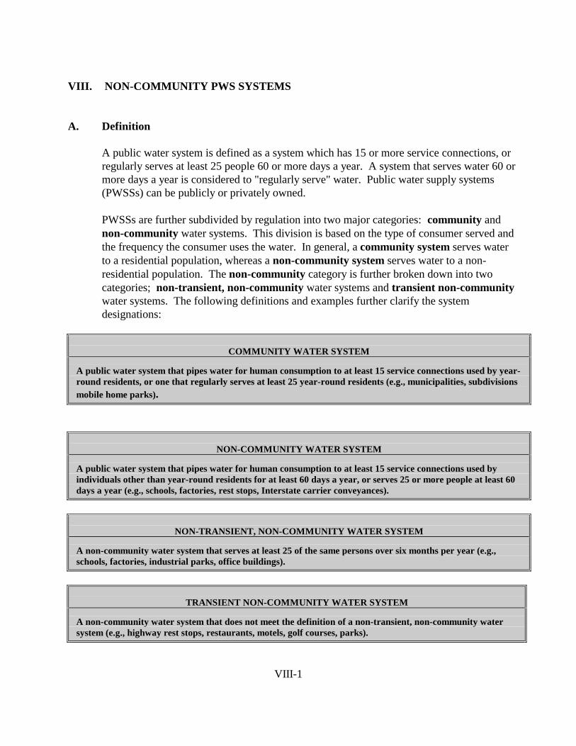
VIII-1
VIII. NON-COMMUNITY PWS SYSTEMS
A. Definition
A public water system is defined as a system which has 15 or more service connections, orregularly serves at least 25 people 60 or more days a year. A system that serves water 60 ormore days a year is considered to "regularly serve" water. Public water supply systems(PWSSs) can be publicly or privately owned.
PWSSs are further subdivided by regulation into two major categories: community andnon-community water systems. This division is based on the type of consumer served andthe frequency the consumer uses the water. In general, a community system serves waterto a residential population, whereas a non-community system serves water to a non-residential population. The non-community category is further broken down into twocategories; non-transient, non-community water systems and transient non-communitywater systems. The following definitions and examples further clarify the systemdesignations:
COMMUNITY WATER SYSTEM
A public water system that pipes water for human consumption to at least 15 service connections used by year-round residents, or one that regularly serves at least 25 year-round residents (e.g., municipalities, subdivisionsmobile home parks).
NON-COMMUNITY WATER SYSTEM
A public water system that pipes water for human consumption to at least 15 service connections used byindividuals other than year-round residents for at least 60 days a year, or serves 25 or more people at least 60days a year (e.g., schools, factories, rest stops, Interstate carrier conveyances).
NON-TRANSIENT, NON-COMMUNITY WATER SYSTEM
A non-community water system that serves at least 25 of the same persons over six months per year (e.g.,schools, factories, industrial parks, office buildings).
TRANSIENT NON-COMMUNITY WATER SYSTEM
A non-community water system that does not meet the definition of a non-transient, non-community watersystem (e.g., highway rest stops, restaurants, motels, golf courses, parks).

VIII-2
Table VIII.1: Examples of Non-Community Water Systems
NON-COMMUNITY PUBLIC WATER SUPPLY SYSTEMS
Non-transient Transient
· Non-residential schools andinstitutions
· Public buildings· Office buildings· Industries· Day care centers· Industrial parks
Anyone that employees at least 25 people.
· Churches· Restaurants· Motels/hotels· Campgrounds· Rest areas (highway)· Parks· Service and gasoline stations· Shopping centers· Airports· Recreation areas· Marinas· Camps/clubs
B. Wellhead Protection and Non-Community PWSS
The protection of ground water quality is becoming more and more important as the costs oftreatment escalates, and fewer resource areas are available to develop new supplies. TheWHPP provides a logical approach for all water systems served by ground water to developthe necessary protection elements to continue providing safe and potable drinking watersupplies.
The State of Indiana's overall objective in creating a State-wide Wellhead Protectionprogram is for all PWSSs to develop and implement effective local WHP plans, includingnon-community systems. The federal Safe Drinking Water Act (SDWA) requires States todevelop programs to protect ground water that supplies wells and wellfields that contributedrinking water to all PWSSs. However, the statutory authority for implementing wellheadprotection in Indiana (IC 13-7-26-6) provides only for community water supply systems. Therefore, a PWSS which meets the criteria for designation as a non-community watersupply is not required to submit a wellhead protection plan.
In order to achieve the State's overall objective of protecting all public water suppliesthrough wellhead protection, the State will require community systems to develop localWHP plans and encourage non-community systems to voluntarily participate in the State'sWHPP. Where a non-community system is proactive, and desires to formally develop
VIII-3
measures for wellhead protection, the State will endorse wellhead protection plansdeveloped by non-community systems which meet the criteria for community planning,delineation, potential source identification, management, and contingency planning that areestablished in this program for community water supply systems.
C. Course of Action
Because the State’s authority to require non-community systems to develop and implementlocal WHP plans is absent, the State will undertake an aggressive campaign to encouragevoluntary participation by all non-community systems. The following discussion provides adescription of the State’s proposed efforts to affect participation by non-community systems.
1. Afford program flexibility to non-community systems to encouragegreater participation:
· Optional use of the 3,000 foot radius as a default wellhead protectionarea (WHPA) delineation (for systems with withdrawal rates lessthan 100,000 gpd);
· Reduced monitoring requirements under the standardized monitoringframework in conjunction with the monitoring waiver programrequirements;
· No schedule requirements for program submittal (i.e., no time frameis mandated for submittal, allowing non-community systems a longerperiod of time to develop programs); and
· Greater flexibility will be afforded by the State in approvingproposed management measures.
2. Provide information and guidance on issues related to local programs,such as:
· Controlling non-point sources of pollution· Suggesting land use activities for wellhead protection areas· Developing and promulgating best management practices· Involving county health departments to serve as an informational
outlets
The IDEM will play an active role to ensure public outreach and show thebenefits of having a WHP plan. Through these efforts the non-communityPWSS will recognize the benefits of having a WHP plan, and gain supportand cooperation for wellhead protection.
VIII-4
3. Provide assistance:
Wellhead Protection (WHP) Training Workshops for:
· IDEM-Drinking Water Field Inspection staff· Public organizations· City officials· County health officials· Non-community public water systems
Training workshops will further educate the key players of WHP andencourage implementation of the program. The workshops will beconducted at various sites throughout the state (i.e., to maximize attendance).
4. Provide assistance with conducting inventories of land use and potentialsources of contamination in WHPAs:
· Develop and provide inventory forms or checklists· Provide instructions on conducting inventories
An inventory of potential contaminant sources will provide opportunity toidentify any past, present, and proposed activities that may be a threat to thewell. By providing systems with generalized inventory forms, the sourceidentification process will be easier to undertake, thereby minimizing stafftime needed to perform the source identification.
5. Assistance with public outreach:
· Provide materials to be used at public hearings or meetings such as,videos, slide presentations, displays, brochures, or handouts;
· Invite county and city health departments to participate in local WHPmeetings;
· Develop written technical assistance materials to distribute to localgovernment and public water supply systems; and
· Respond to telephone inquires for information on wellheadprotection from local officials.
Close coordination and communication between local officials and the

VIII-5
public is a key element to a successful WHP plan. Public outreach has beenand will continue to be an ongoing process. In addition, by providingtargeted technical assistance and guidance documents which presentdemonstrated methods and techniques for potential source management,systems will be able to apply the management practices that suit their uniquecircumstances. This will maximize effectiveness and provide alternatives forsystems to implement.
6. WHP questions will be integrated into:
· Sanitary Surveys (updated every 5 years w/o disinfection, 10 years w/disinfection)
· Well site surveys· VOC vulnerability forms· Ground water under the direct influence of surface water
determinations· Monitoring waiver packages
Components of wellhead protection are currently being integrated into fieldinspections. The goal is to see the level of WHP the PWSS is currentlyimplementing and to provide on-site guidance and encouragement to thesystems. This approach is an educational tool and will help guide thesystems to achieve an effective WHP plan.
7. Additional incentives for WHP include:
· Protection of ground water· Potential for reductions in monitoring· Protection of drinking water· Protection of public health· Information and guidance regarding monitoring and sampling
activities specific to the needs of non-community systems.
The non-community field staff of the Drinking Water Branch along with the WellheadProtection staff of the Ground Water Section will strongly encourage the non-communityPWSS to undertake Wellhead Protection through the incentives listed above. Theincentives are proposed as a means to encourage local participation which is an importantcomponent. For successful ground water protection, there must be a partnership betweenlocal governments and appropriate county and State agencies.
IX. Public Participation
A. Summary of Public Participation Process...IX-1
B. Implementation and Phase-In Process.........IX-2
IX-1
IX. PUBLIC PARTICIPATION AND IMPLEMENTATION
A. Summary of Public Participation Process
Public input is a crucial part of developing and implementing an effective WellheadProtection Program (WHPP). To facilitate public involvement in the development of theIndiana WHPP, the Indiana Ground Water Task Force (GWTF) formed a workgroup toprovide assistance to the IDEM. This WHP workgroup consists of representatives of thewater supply industry, well drillers, hydrogeologic and planning consultants, StateAgencies, and industrial and commercial facility operators. The WHP workgroup has heldseveral meetings since its inception to facilitate program development and build consensuson the numerous issues the program addresses.
Program development has been an ongoing process since 1989 and has involved public andState agency input throughout. Recent versions of the program, including the October 1993and June 1994 drafts, were provided to IDEM Drinking Water Branch programrepresentatives for review. In addition, these drafts were provided to members andparticipants of the GWTF, all mayors of Indiana cities and towns, county commissioners,one major library per county, all county health departments, all community public watersupply system (PWSS) operators, and the WHP workgroup.
For each version of the program, a 30-day comment period was provided in whichnumerous comments were received by the IDEM. Response to comments includedrevisions to the draft WHPP. Following the June 1994 version, a summary of commentsreceived and proposed revisions were developed and distributed.
Concurrently with formal submittal of the Indiana WHPP to the Regional Administrator ofU.S. EPA, the State public noticed the availability of the final program in the IndianaRegister (February 1, 1995). This public notice notified the public of the completion of theprogram development process and identified where copies of the program could be obtained(at the main library branch in each county of the State). The public notice provided a 30-day comment period and notice of availability for public hearing on the final program. Following the comment period, no public comments were received or any requests forpublic hearing on the program.
Because Indiana’s Wellhead Protection program is mandatory for all community publicwater supply systems (CPWSS) using ground water as the source of supply, the programoutlined in this document will essentially be codified in the Indiana Administrative Code(IAC). The process for promulgating a rule in the State of Indiana requires the State to holdpublic hearings before the Indiana Water Pollution Control Board and publish all commentson the rule in the Indiana Register. Therefore, Indiana’s Wellhead Protection program complies with the requirements of Section 1428(b) of the federal Safe Drinking Water Act

IX-2
which requires the opportunity for public hearing on the State program through this processand those described above. Copies of all comments received, including the responsespublished by the IDEM in the Indiana Register will be provided to the U.S. EPA Region 5following publication.
The Indiana Wellhead Protection rule (327 IAC 8-4.1) final adoption was passed by the Water Pollution Control Board July 10, 1996. It is expected to become rule in January 1997.
Formal public involvement will also be a part of the WHP plan at the local level. Indianawill continue to utilize public workshops, educational seminars, the State Fair, articles, andnews releases as effective public involvement and educational tools. Numerous educationalseminars and workshops have been conducted by the Indiana Department of EnvironmentalManagement (IDEM) throughout the State. WHP presentations were conducted for waterpurveyors, regional planning groups, and professional associations during 1992 through1995. IDEM participated in a day long teleconference to educate people about the WHPPon July 16, 1993.
B. Implementation and Phase-In Process
Development and implementation of a WHP plan requires a community to formulatespecific time frames for gathering technical and land-use information. After acomprehensive plan is developed and the protection approaches have been prepared, publicsupport must be generated for the implementation of the plan. It is critical that localresidents are kept informed of the progress during program development to ensure supportby all sectors.
The following Phase-in guidelines will be maintained by the State throughout the WHPPimplementation process:
Fiscal Year 1996:
· Initiate the development of Technical Assistance and Public EducationalDocuments;
· Obtain formal approval of the Indiana WHPP by U.S. EPA, Region 5;
· Promulgate regulations for wellhead protection through the rule adoption process ofthe Indiana Water Pollution Control Board (IWPCB);
· Develop WHP application forms;

IX-3
· Complete a survey of community and non-community PWSSs, to determine thelevel of knowledge and understanding of the program and the specific informationneeds and concerns of the systems with respect to WHP;
· Review new well-site applications;
· Initiate educational outreach program to the public and PWSSs.
Fiscal Year 1997:
· Finalize plans for obtaining full staff at the State level for the comprehensiveWHPP;
· Finalize Technical Assistance and Public Educational documents;
· Review applications for WHP plans;
· Develop and finalize a computerized monitoring program to track the submittal andapproval of WHP plans;
· Track compliance of the WHP plans through inspections and reportingrequirements.

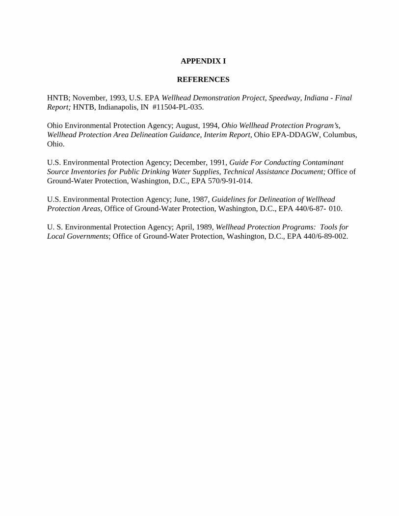
APPENDIX I
REFERENCES
HNTB; November, 1993, U.S. EPA Wellhead Demonstration Project, Speedway, Indiana - FinalReport; HNTB, Indianapolis, IN #11504-PL-035.
Ohio Environmental Protection Agency; August, 1994, Ohio Wellhead Protection Program’s,Wellhead Protection Area Delineation Guidance, Interim Report, Ohio EPA-DDAGW, Columbus,Ohio.
U.S. Environmental Protection Agency; December, 1991, Guide For Conducting ContaminantSource Inventories for Public Drinking Water Supplies, Technical Assistance Document; Office ofGround-Water Protection, Washington, D.C., EPA 570/9-91-014.
U.S. Environmental Protection Agency; June, 1987, Guidelines for Delineation of WellheadProtection Areas, Office of Ground-Water Protection, Washington, D.C., EPA 440/6-87- 010.
U. S. Environmental Protection Agency; April, 1989, Wellhead Protection Programs: Tools forLocal Governments; Office of Ground-Water Protection, Washington, D.C., EPA 440/6-89-002.


APX II-1
APPENDIX II
Items to be Considered During Selection of Delineation Method(After OEPA, 1994, Wellhead Protection Area Delineation Guidance.)
Hydrogeologic Setting
1. Aquifer material - This addresses the type of material the water is drawn from, if it isconsolidated or unconsolidated. If it is unconsolidated, is it sand, gravel or sand andgravel? If it is consolidated, is it limestone, fractured limestone or sandstone?
2. Hydraulic properties - The size of a well’s capture zone is affected by the hydraulicproperties of the aquifer. These include hydraulic conductivity, porosity and transmissivity. These properties are intrinsic to the aquifer material and do not vary significantly withtime. Hydraulic conductivity is one of the most important determinants of flow velocity.
3. Aquifer confinement conditions - Aquifers can be confined, unconfined or semi-confined. This information is important to assess the aquifer’s vulnerability to contamination. Byassessing the aquifer’s vulnerability to contamination, the need for accuracy of delineationcan also be addressed. If the PWSS cannot provide for the desired degree of accuracy, theWHPA can be expanded by using a TOT of greater than five years. Most models alsorequire confinement conditions be defined as an input parameter.
4. Flow boundaries - Ground water flow boundaries can affect the size and orientation of acapture zone significantly and many of the widely used computer flow models requireknowledge of their location and orientation.
5. Local flow gradients and directions - Local flow gradients and directions may have themost significant effect on the size, shape and orientation of a capture zone. For example,flow boundaries may include, a bedrock valley wall, surface water bodies, and ground waterflow divides.
Management Plans
1. Current and anticipated size of system - The size of the system needs to be consideredwhen selecting the appropriate delineation method. The more people served by the system,the greater the population at risk if the delineation area is significantly inaccurate. A largesystem pumping more water at a greater rate will have a larger capture zone around the wellfield than a smaller water system.

APX II-2
2. WHP goals and management strategies - PWSS and communities should explore themost feasible management options available even before delineating the well field, as thismay aid in the choice of a delineation method. For example, those systems consideringzoning restrictions or land purchases may desire a highly accurate delineation to avoidrestricting a greater area than necessary. While the costs of a more accurate delineation maybe high, applying management options to the wrong area, or an area much larger thannecessary, could be more expensive in the long run.
3. Defensibility of chosen method - An advanced delineation method may be desirable if theaccuracy of the delineated area will be challenged. This may occur when the WHPAextends into other political jurisdictions or if the management strategies include zoningrestrictions.
4. Well field geometry - The spatial relationship between the existing wells or planned wellsis important when pumping interference needs to be considered. Not all models take thisfactor into account.
5. Nearby pumping centers - Nearby pumping centers can distort the shape of the WHPA byacting as a barrier to ground water flow. Such pumping centers may include industrialwells, other public water supply wells, and agricultural wells. It is important to know wherethese pumping centers are located in relation to the well field and to use a method that canmodel multiple wells if the nearby pumping centers appear close enough to influence theWHPA.

APX III-1
APPENDIX III
ABBREVIATIONS and ACRONYMS
BMP - Best Management Practices
CERCLA - Comprehensive Environmental Response, Compensation, and Liability Act
CERCLIS - Comprehensive Environmental Response, Compensation and Liability InformationSystem
CES - Cooperative Extension Service
CPWSS - Community Public Water Supply System
DOC - Department of Commerce
DWB -Drinking Water Branch
EPA - Environmental Protection Agency
GPD - Gallons Per Day
GPS - Global Positioning System
GWTF - Ground Water Task Force
IAC - Indiana Administrative Code
IC - Indiana Code
IDEM - Indiana Department of Environmental Management
IDNR - Indiana Department of Natural Resources
INDOT - Indiana Department of Transportation
ISDH - Indiana State Department of Health
IURC - Indiana Utility Regulatory Commission
IWPCB - Indiana Water Pollution Control Board
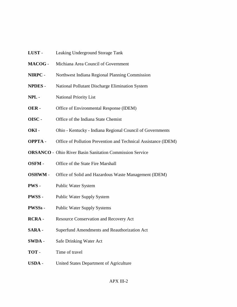
APX III-2
LUST - Leaking Underground Storage Tank
MACOG - Michiana Area Council of Government
NIRPC - Northwest Indiana Regional Planning Commission
NPDES - National Pollutant Discharge Elimination System
NPL - National Priority List
OER - Office of Environmental Response (IDEM)
OISC - Office of the Indiana State Chemist
OKI - Ohio - Kentucky - Indiana Regional Council of Governments
OPPTA - Office of Pollution Prevention and Technical Assistance (IDEM)
ORSANCO - Ohio River Basin Sanitation Commission Service
OSFM - Office of the State Fire Marshall
OSHWM - Office of Solid and Hazardous Waste Management (IDEM)
PWS - Public Water System
PWSS - Public Water Supply System
PWSSs - Public Water Supply Systems
RCRA - Resource Conservation and Recovery Act
SARA - Superfund Amendments and Reauthorization Act
SWDA - Safe Drinking Water Act
TOT - Time of travel
USDA - United States Department of Agriculture

APX III-3
USDA-NRCS -United States Department of Agriculture - Natural Resources Conservation Service
USGS - United States Geological Survey
UST - Underground Storage Tank
WHP -Wellhead Protection
WHPA - Wellhead Protection Area
WHPP - Wellhead Protection Program


APX IV-1
APPENDIX IV
Arbitrary Fixed Radius Summary Report
I. Introduction
The 1986 amendments to the federal Safe Drinking Water Act require states to formally protectground water which supplies public water systems. Section 1428 of the SDWA requires States todevelop plans which describe, among other things, determination of wellhead protection areas(WHPAs) for each public well or wellfield. The methods for delineating a wellhead protectionarea (WHPA) were selected by the IDEM(in conjunction with the Wellhead Workgroup) basedon ease of use and understanding, economy of development and implementation, ability ofmethod to account for local geology, and technical defensibility. Five methods were endorsed bythe IDEM and the Wellhead Workgroup for delineation of a WHPA; 1.) Fixed Radius 2.)Analytical 3.)Semi-analytical, 4.) Numerical flow/solute transport, and 5.) Hydrogeologicmapping.
The fixed radius method of defining a WHPA is obtained by applying a circle with a definedradius and the center at the well. The radius is intended to approximate the distance of a 5-yrTOT . The IDEM initially proposed a 4,500 ft. radius in the program. After further evaluationand discussion with the Wellhead Workgroup, a 3,000’ radius was selected. The purpose of thisreport is to:1) provide the rationale for the use of a fixed radius method in Indiana, 2) documentthe process and methods used to determine the representative radius, 3) give examples of wherethe fixed radius method may not be appropriate and 4) discuss how IDEM review WellheadProtection Programs (WHPP) submitted using fixed radius to define the WHPA.
II. Rationale for Fixed Radius in Indiana
In Indiana, the fixed radius method is allowed to be used by small systems. In preliminarymodeling of WHPAs with high transmissivities it was found capture zones are represented as anarrow strip of land extending toward the source area (Fig. 1) (Mohammed Iqbal, verbalcommunication, 1994). This narrow strip is probably only a part of the true WHPA, which is probably larger due to transient flow dynamics in the system. The cost of gathering data todetermine the direction and value of the transient flow, the cost of modeling a dynamic system,and the financial resources of small systems are the rationale for allowing systems to use a fixedradius.
To limit the use of fixed radius method to smaller systems only, the fixed radius method wasendorsed for use by PWSSs which qualify as a non-significant water withdrawal facility asdefined by IN 13-2-2.5 . A nonsignificant ground water withdrawal facility means the groundwater withdrawal facility of a person that, in the aggregate, has a withdrawal capability of lessthan one hundred thousand (100,000) gallons of ground water in one day.

APX IV-2
This page reserved for Figure 1

APX IV-3
III. Fixed Radius WHPA vs. True WHPA
The shape of a WHPA delineated by fixed radius method is, by definition, a circle around a well,while the shape of a WHPA delineated by an analytical, semi-analytical or numerical method isusually an elongated ellipse. (Fig. 2). It can be seen in Fig 2 that, if a fixed radius method isused, a much larger WHPA maybe delineated and management practices must be applied to areaswhich may not be included in a WHPA delineated using another method. In choosing adelineation method it is important to consider: 1) the goals of the management strategy as chosenby the local planning team, 2) the cost incurred by applying the management plans over areaswhich may not be in the WHPA and 3) the cost of delineating by other methods.
V Determination of radius
A. First Modeling Efforts
1. Goal The goal of the IDEM’s first modeling effort was to calculate the distance of a 5-yr. TOTusing transmissivities which represent the extreme values found throughout Indiana. Inthis manner, the fixed radius would include all hydrogeologic settings in the state andcould be used with no review necessary by the IDEM. In addition, the effect of varyingthe value of transmissivity and the pumping rate on the capture zone was qualitativelyevaluated.
2. Model and ParametersThe first model effort employed WHPA's, GPTRAC (Blandford and Huyakorn)1module. WHPA/GPTRAC is a semi-analytical method with a time-related capture zonedelineation for simple cases using analytical velocity computation techniques. WHPA/GPTRAC assumes a steady state system with 2-dimensional flow and ahomogeneous, isotropic aquifer. Input parameters not varied in model runs are listed inTable 1. Variations of T and Q, with resultant distance of 5-yr. TOT are listed in Table 2.
Table 1. Fixed Parameters of Initial Model
Parameter Type Parameter Value
Aquifer type confined
Thickness 100 ft.
Porosity .25
Gradient .005

APX IV-4
This page reserved for Figure 2

APX IV-5
Table 2. Values of Transmissivity and Pumping Rates withResultant Distance of 5-yr. TOT
Transmissivity(gpd/ft)
Pumping Rate(gpd)
5-year TOTDistance
(feet)
100,000 100,000 4,500
100,000 80,000 4,500
100,000 60,000 4,500
100,000 40,000 4,500
100,00 20,000 4,500
50,000 100,000 2,800
50,000 80,000 2,800
50,000 60,000 2,800
50,000 40,000 2,800
50,000 20,000 2,800
20,000 100,000 2,200
20,000 50,000 2,200
20,000 20,000 2,200
3. ResultsBased on the assumption that the WHPA delineated using fixed radius should coverhydrogeologic scenarios with the highest transmissivity values found in the state, a radius of4,500 feet was proposed and presented in the June 1994 draft of the Indiana WHPP. With aradius of 4,500 feet, any PWSS being a non-significant water user as defined by IC 13-2-2.5-2(1)could use the fixed radius method with no review from the department.
4. Sensitivity AnalysisA formal sensitivity analysis was not performed on the initial model but, in reviewing Table 2, itcan be seen that, in general, increasing the transmissivity value increases the distance of theWHPA, while increasing the discharge of the simulated pumping well increases the width of theWHPA.

APX IV-6
B. Reevaluation of 4,500’ radius
The fixed radius distance of 4,500 feet was incorporated in the June, 1994 draft of the Indiana WellheadProtection Plan and provided to the wellhead workgroup. Numerous comments in response to this draft,and in particular, the 4,500 foot radius, were received by the IDEM. Many comments indicated the4,500’ radius was too large and would not apply to the majority of systems in Indiana. That is, most ofsystems in Indiana do not have high transmissivity values and therefore would not need such a largefixed radius. Based upon these comments, the IDEM began to reevaluate the 4,500 foot radius.
C. Second Modeling EffortC. Second Modeling Effort
1. Goal. GoalThe goal of the second modeling effort was to determine a radius which would include the majority ofhydrogeologic scenarios in the state. That is the radius determined should be equal to or greater than thedistance of a 5-yr. TOT if calculated by the majority of PWSSs in the state.
2. Modeling. ModelingThe modeling employed two types of models; WHPA/GPTRAC and MODFLOW/MODPATH(McDonald and Harbaugh, 1988)2. WHPA/GPTRAC was previously discussed in the summary of thefirst modeling efforts. MODFLOW is a numerical simulation which derives the distribution ofhydraulic head across a model grid, or water table elevations. The ground water table data is passed toMODPATH which tracks particles backward in time to delineate the WHPA.
3. Modeling Parameters. Modeling ParametersBased on the goal set forth for the second modeling effort and considering the first modeling effort’sinformal sensitivity analysis findings, the average value of transmissivity for unconsolidated aquiferswas investigated. IDEM choose to also determine the average hydraulic gradient throughout the state. Parameter values used to calculate the 3,000' radius are presented in Table 4.
a. Investigation of Transmissivity Values and Hydraulic Gradientsa. Investigation of TransmissivityValues and Hydraulic GradientsIDEM conducted a review of transmissivity values and hydraulic gradients found in publishedreports. This review was not exhaustive, but consisted of publications which were readily available. For transmissivity, if a range was reported, a modal value was calculated; if an average value wasreported, that average value was used. The transmissivity values are listed in Table 3 and comparedin fig. 3. From the compiled data of transmissivity values, a value of 20,000 ft2/d for transmissivitywas determined to be the median value and used as the transmissivity value in the second modelingeffort. For hydraulic gradient, if a average value was reported, that value was used, if only a map ofhydraulic head across the reported area was reported, a average gradient was measured off the map. These average values are reported in Table 3. A average value for .001 was calculated.
APX IV-7
This page reserved for Figure 3

APX IV-8
Table 3. Reported Values of Transmissivity and Hydraulic Gradient
Reporting Region Transmissivity (gpd/ft)
Transmissivity (ft2/d)
HydraulicGradient
Upper Wabash Basin (Tate,Et al, 1973)3
175,000 23,000 .001
Maumee Basin (Pettijohnand Davis, 1973)4
150,000 20,000 .003
Madison (Laphan, 1981)5 190,000 21,000 .001
Hamilton & Tipton(Airhood, 1982) 4
100,000 11,000 .001
Delaware & Henry (Airhoodand others, 1982)7
190,000 22,000 .002
Porter & LaPorte Co (Rosenshein and Hunn,1968)8
85,000 10,000 .001
Marion Co (Meyer andothers, 1975)9
100,000 12,000 .002
Waterwater Basin (IDNR,1988)10
100,000 10,000 .001
Kankakee Basin (IDNR,1987)11
255,000 29,000 .001
St. Joe Basin (IDNR,1987)12
350,000 40,000 .002
Elkhart Co (Duwelius andSilcox, 1991)13
176,000 20,000 .001
b. AquiferThickness (b) - the value of 50 feet was chosen as the simulated thickness of the aquifer,and is different from 100 foot value used in the first modeling effort. The thickness of the aquiferwas changed due to the fact that the models used assume full penetration of the well throughout thesimulated aquifer and generally, small PWSSs have a maximum screened interval of 20 feet. Therefore, the 50 feet of aquifer simulated is the portion of the aquifer affected by pumping. Achange to 50’ thickness isa conservative choice; as the thickness of the aquifer becomes greater, thedistance of the TOT also becomes greater.
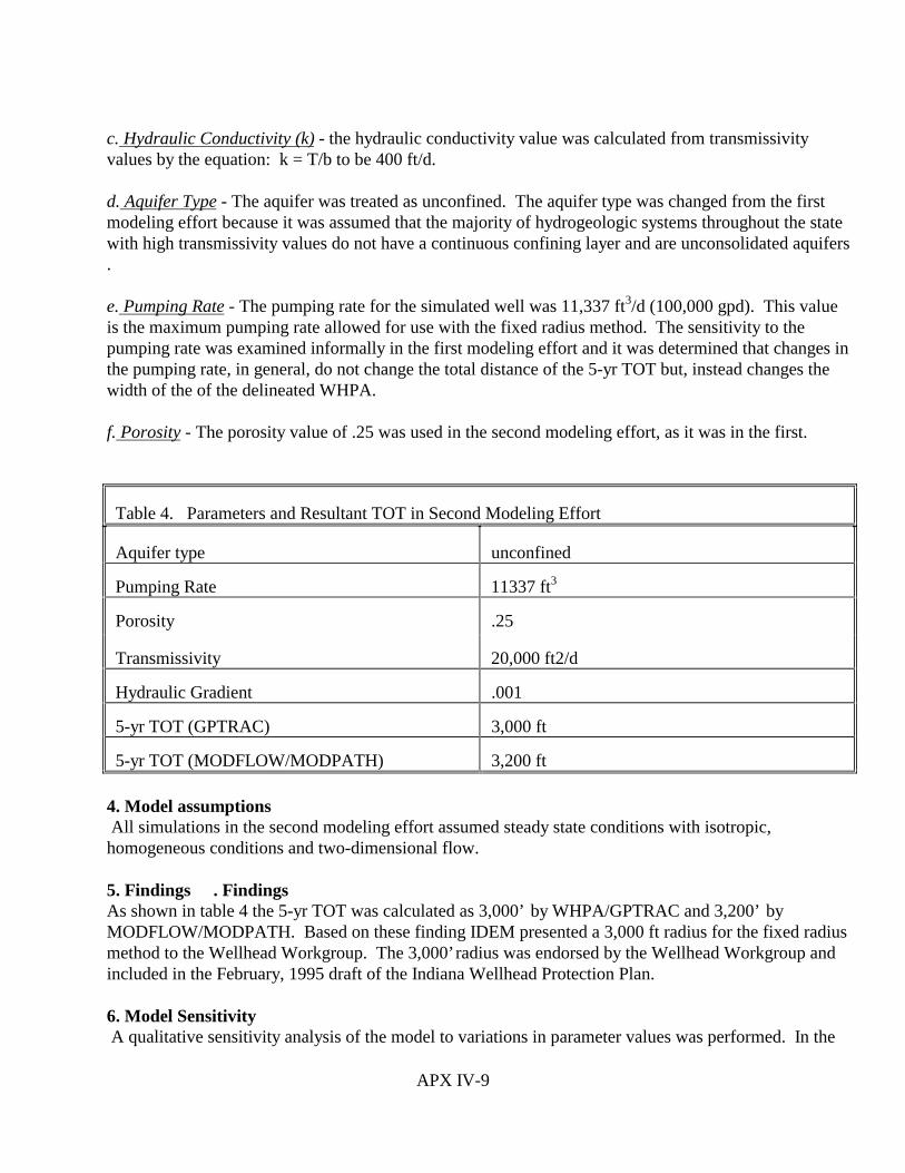
APX IV-9
c. Hydraulic Conductivity (k) - the hydraulic conductivity value was calculated from transmissivityvalues by the equation: k = T/b to be 400 ft/d.
d. Aquifer Type - The aquifer was treated as unconfined. The aquifer type was changed from the firstmodeling effort because it was assumed that the majority of hydrogeologic systems throughout the statewith high transmissivity values do not have a continuous confining layer and are unconsolidated aquifers.
e. Pumping Rate - The pumping rate for the simulated well was 11,337 ft3/d (100,000 gpd). This valueis the maximum pumping rate allowed for use with the fixed radius method. The sensitivity to thepumping rate was examined informally in the first modeling effort and it was determined that changes inthe pumping rate, in general, do not change the total distance of the 5-yr TOT but, instead changes thewidth of the of the delineated WHPA.
f. Porosity - The porosity value of .25 was used in the second modeling effort, as it was in the first.
Table 4. Parameters and Resultant TOT in Second Modeling Effort
Aquifer type unconfined
Pumping Rate 11337 ft3
Porosity .25
Transmissivity 20,000 ft2/d
Hydraulic Gradient .001
5-yr TOT (GPTRAC) 3,000 ft
5-yr TOT (MODFLOW/MODPATH) 3,200 ft
4. Model assumptions All simulations in the second modeling effort assumed steady state conditions with isotropic,homogeneous conditions and two-dimensional flow.
5. Findings . Findings As shown in table 4 the 5-yr TOT was calculated as 3,000’ by WHPA/GPTRAC and 3,200’ byMODFLOW/MODPATH. Based on these finding IDEM presented a 3,000 ft radius for the fixed radiusmethod to the Wellhead Workgroup. The 3,000’ radius was endorsed by the Wellhead Workgroup andincluded in the February, 1995 draft of the Indiana Wellhead Protection Plan.
6. Model Sensitivity A qualitative sensitivity analysis of the model to variations in parameter values was performed. In the
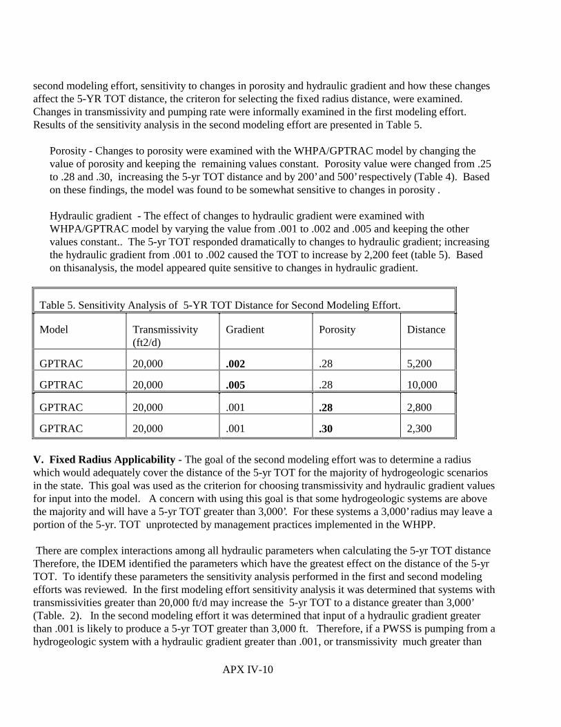
APX IV-10
second modeling effort, sensitivity to changes in porosity and hydraulic gradient and how these changesaffect the 5-YR TOT distance, the criteron for selecting the fixed radius distance, were examined. Changes in transmissivity and pumping rate were informally examined in the first modeling effort. Results of the sensitivity analysis in the second modeling effort are presented in Table 5.
Porosity - Changes to porosity were examined with the WHPA/GPTRAC model by changing thevalue of porosity and keeping the remaining values constant. Porosity value were changed from .25to .28 and .30, increasing the 5-yr TOT distance and by 200’ and 500’ respectively (Table 4). Basedon these findings, the model was found to be somewhat sensitive to changes in porosity .
Hydraulic gradient - The effect of changes to hydraulic gradient were examined withWHPA/GPTRAC model by varying the value from .001 to .002 and .005 and keeping the othervalues constant.. The 5-yr TOT responded dramatically to changes to hydraulic gradient; increasingthe hydraulic gradient from .001 to .002 caused the TOT to increase by 2,200 feet (table 5). Basedon thisanalysis, the model appeared quite sensitive to changes in hydraulic gradient.
Table 5. Sensitivity Analysis of 5-YR TOT Distance for Second Modeling Effort.
Model Transmissivity(ft2/d)
Gradient Porosity Distance
GPTRAC 20,000 .002 .28 5,200
GPTRAC 20,000 .005 .28 10,000
GPTRAC 20,000 .001 .28 2,800
GPTRAC 20,000 .001 .30 2,300
V. Fixed Radius Applicability - The goal of the second modeling effort was to determine a radiuswhich would adequately cover the distance of the 5-yr TOT for the majority of hydrogeologic scenariosin the state. This goal was used as the criterion for choosing transmissivity and hydraulic gradient valuesfor input into the model. A concern with using this goal is that some hydrogeologic systems are abovethe majority and will have a 5-yr TOT greater than 3,000’. For these systems a 3,000’ radius may leave aportion of the 5-yr. TOT unprotected by management practices implemented in the WHPP.
There are complex interactions among all hydraulic parameters when calculating the 5-yr TOT distanceTherefore, the IDEM identified the parameters which have the greatest effect on the distance of the 5-yrTOT. To identify these parameters the sensitivity analysis performed in the first and second modelingefforts was reviewed. In the first modeling effort sensitivity analysis it was determined that systems withtransmissivities greater than 20,000 ft/d may increase the 5-yr TOT to a distance greater than 3,000’(Table. 2). In the second modeling effort it was determined that input of a hydraulic gradient greaterthan .001 is likely to produce a 5-yr TOT greater than 3,000 ft. Therefore, if a PWSS is pumping from ahydrogeologic system with a hydraulic gradient greater than .001, or transmissivity much greater than

APX IV-11
20,000 ft2/d, a 3000’ radius may be too small for that system and the use of the fixed radius method maynot be appropriate. In these cases, after review of available data, IDEM may require the PWSS to useanother approved method to delineate the WHPA.
VI. Review Criteria for Fixed Radius methodIn reviewing a WHPA which has used a fixed radius method the IDEM will estimate if the PWSS hashydraulic parameters which fall above or below the average parameters which have been used tocalculate the 3000’ radius. For example, is the transmissivity for the area of the PWSS much greaterthan 20,000 ft2/d? To determine the hydrogeologic parameter values IDEM may examine or use toolssuch as:
1. The pumping history of the PWSS; 2. Published reports of the area in which the PWSS is located;3. Unpublished reports and files held at the IDEM (e.g., maps and descriptions of hydrogeologic
settings in Indiana as prepared by the Indiana Geological Survey;4. The written justification submitted with the WHPA; or5. Analytical or Semi-Analytical Modeling.
VII. Submittal Requirements for Fixed Radius Delineation
Systems which do use the fixed radius will have significantly less submittal requirements compared tosystems which delineate with other methods. A PWSS that delineates the WHPA using the FixedRadius Method must submit the following data to the department:
1. A map depicting the following:a. The wellhead protection area boundary;b. The PWSS pumping well(s); andc. Other pumping sources in the area.
2. A topographic map of the area3. Well logs of the PWSS pumping well(s).
VIII. Conclusions
The methods for delineating WHPA were selected based on: 1) ease of use and understanding, 2)economy of development and implementation, 3) ability of method to account for local geology and 4)technical defensibility. Because of the cost of modeling and the uncertainty of WHPA boundaries inpossible transient situations, the IDEM and the Wellhead Workgroup endorsed the use of the fixedradius method for systems defined as a non-significant water users by IC 13-2-2.5. Based on modelingefforts, initially the IDEM proposed a 4,500’ radius to delineate a 5-yr TOT for all hydrogeologic settingin Indiana. Any PWSS being a non-significant water user could delineate using the 4,500’ radius with noreview necessary by IDEM. After receiving numerous comments suggesting that most system in Indianawould not need such a large radius to delineate the WHPA, IDEM reevaluated the 4,500’ radius.

APX IV-12
Based on modeling efforts simulated an unconfined aquifer and using a porosity of .25, transmissivity of20,000 ft2/d, and a hydraulic gradient of .001, the IDEM concluded that a 3,000’ fixed radius will delineate a 5-yr TOT which accounts for the majority of hydrogeological systems in Indiana. The fixedradius method with a 3,000’ radius is available to any PWSS being a non-significant water. The IDEMwill review the WHPP submittal to determine if the parameters in the area of the PWSS are greater thanthose used to calculate the 3000’ radius. If the parameters are greater than those used to calculate the3000’ radius and it is deemed by the IDEM that the 5-yr TOT would be greater than 3,000’, the IDEMmay require that the PWSS utilize another method to delineate the WHPA.

APX IV-13
REFERENCES CITED


APX IV-1
INDIANA WELLHEAD PROTECTION RULE
327 IAC 8-4.1
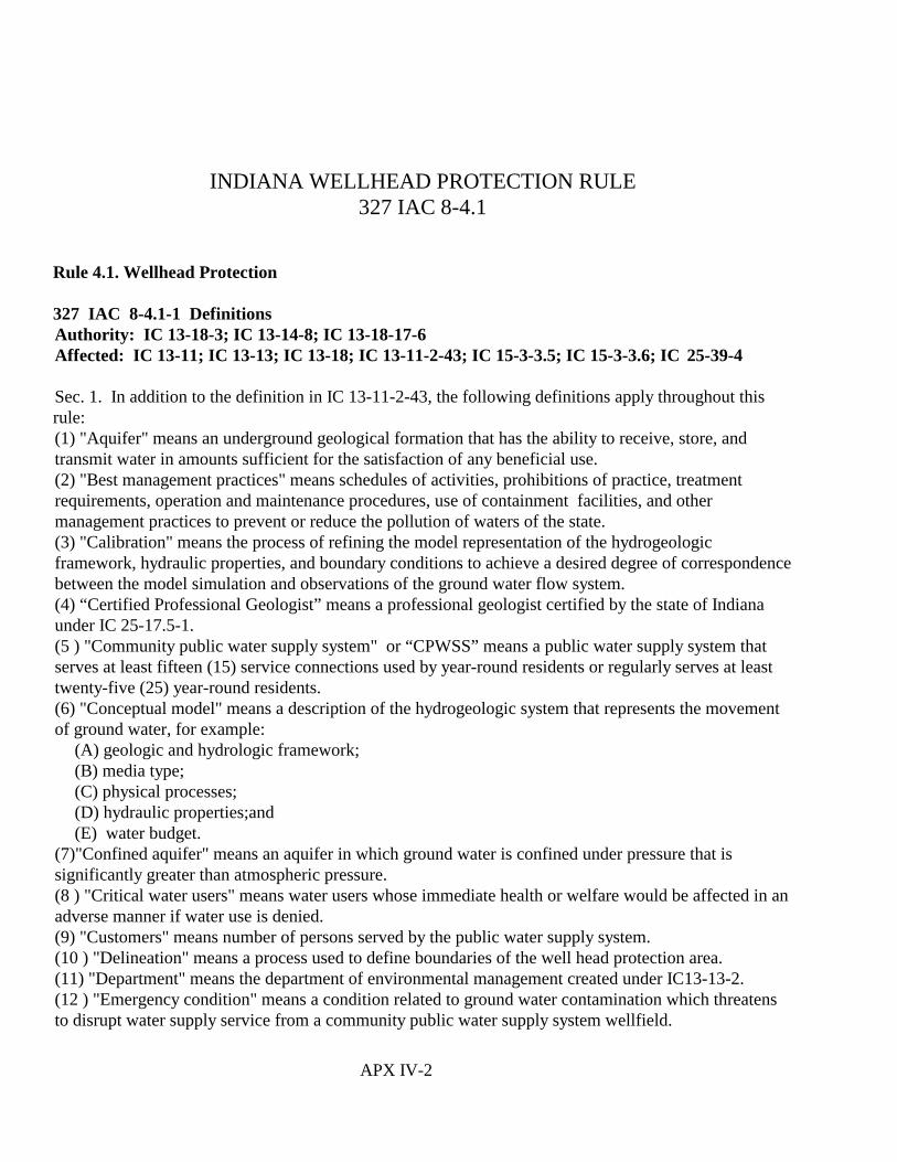
APX IV-2
INDIANA WELLHEAD PROTECTION RULE327 IAC 8-4.1
Rule 4.1. Wellhead Protection
327 IAC 8-4.1-1 DefinitionsAuthority: IC 13-18-3; IC 13-14-8; IC 13-18-17-6Affected: IC 13-11; IC 13-13; IC 13-18; IC 13-11-2-43; IC 15-3-3.5; IC 15-3-3.6; IC 25-39-4
Sec. 1. In addition to the definition in IC 13-11-2-43, the following definitions apply throughout thisrule:(1) "Aquifer" means an underground geological formation that has the ability to receive, store, andtransmit water in amounts sufficient for the satisfaction of any beneficial use.(2) "Best management practices" means schedules of activities, prohibitions of practice, treatmentrequirements, operation and maintenance procedures, use of containment facilities, and othermanagement practices to prevent or reduce the pollution of waters of the state. (3) "Calibration" means the process of refining the model representation of the hydrogeologicframework, hydraulic properties, and boundary conditions to achieve a desired degree of correspondencebetween the model simulation and observations of the ground water flow system.(4) “Certified Professional Geologist” means a professional geologist certified by the state of Indianaunder IC 25-17.5-1.(5 ) "Community public water supply system" or “CPWSS” means a public water supply system thatserves at least fifteen (15) service connections used by year-round residents or regularly serves at leasttwenty-five (25) year-round residents.(6) "Conceptual model" means a description of the hydrogeologic system that represents the movementof ground water, for example:
(A) geologic and hydrologic framework;(B) media type;(C) physical processes;(D) hydraulic properties;and(E) water budget.
(7)"Confined aquifer" means an aquifer in which ground water is confined under pressure that issignificantly greater than atmospheric pressure.(8 ) "Critical water users" means water users whose immediate health or welfare would be affected in anadverse manner if water use is denied.(9) "Customers" means number of persons served by the public water supply system.(10 ) "Delineation" means a process used to define boundaries of the well head protection area.(11) "Department" means the department of environmental management created under IC13-13-2. (12 ) "Emergency condition" means a condition related to ground water contamination which threatensto disrupt water supply service from a community public water supply system wellfield.

Indiana Wellhead Protection Rule Page 3
(13 ) "Hydrogeology" means the study of the geology of ground water, with particular emphasis on thechemistry and movement of water.(14 ) "Hydrostratigraphic unit" means a grouping of geologic units of similar hydrogeologic properties,for example, aquifers and confining units.(15) "Large public water supply system" means a public water supply system serving greater than fiftythousand (50,000) customers.(16 ) "Medium public water supply system" means a public water supply system serving from threethousand three hundred one (3,301), up to and including, fifty thousand (50,000) customers.(17 ) "Model" means an investigative technique using a mathematical or physical representation of asystem or theory that accounts for all or some of its known properties.(18 ) "Pesticide review board" means the Indiana pesticide review board created by IC 15-3-3.5 tocollect, analyze, and interpret information on matters relating to the use of pesticides.(19 ) "Potential source of contamination" means a facility, site, practice, or activity that possesses theability to contaminate ground water.(20 ) "Public water supply system" or "PWSS" means a public water supply for the provision to thepublic of piped water for human consumption if such a system has at least fifteen (15) serviceconnections or regularly serves an average of at least twenty-five (25) individuals daily at least sixty (60)days out of the year.(21 ) “Qualified ground water scientist" means an individual who possesses a bachelor's degree or higherin the physical sciences, for example geology, or engineering with a sufficient level of experience tomake sound professional judgments regarding site characterization and hydrogeology. This level ofexperience may be demonstrated by certification or registration as a professional geologist or engineer,either of whom shall have education or professional experience in hydrogeology or ground waterhydrology.(22 ) "Sanitary setback" means an area established around a CPWSS production well to protect groundwater from direct contamination.(23) "Small public water supply system" means a public water supply system serving up to andincluding three thousand three hundred (3,300) customers.(24 ) "State chemist" means the office of the Indiana state chemist authorized by IC 15-3-3.5 and IC 15-3-3.6 to administer the use, application, storage, mixing, loading, transportation, and disposal ofpesticides in Indiana under those chapters.(25) "Time of travel" or "TOT" means the calculated length of time a particle of water takes to reach aCPWSS production well from a certain point.(26 )"Time of travel (TOT) threshold" means a threshold determined by the community or CPWSS tosuit the hydrogeologic conditions and needs of the community; however, a minimum five (5) year TOTfor modeled wellhead protection areas and three thousand (3,000) feet for fixed radius wellheadprotection area is allowed.(27 ) "Wellhead protection area" or "WHPA" means the surface and subsurface area, delineated by fixedradius, hydrogeological mapping, analytical, semianalytical, or numerical flow/solute transport methods,which contributes water to a CPWSS production well or wellfield and through which contaminants arelikely to move through and reach the well within a specified period.(28 ) "Wellhead protection program" or "WHPP" means a program to sustain drinking water quality inground waters that supply public water supply wells and wellfields. The program is mandated by the1986 amendments to the Federal Safe Drinking Water Act, Title II, Section 205, Subsection 1428.

Indiana Wellhead Protection Rule Page 4
(28 ) "Well log" means a drilling record that describes the subsurface formations that have been drilledthrough and gives details of well completion as required by IC 25-39-4 and 310 IAC 16-2-6.(Water Pollution Control Board; 327 IAC 8-4.1-1)
327 IAC 8-4.1-2 Applicability of ruleAuthority: IC 13-18-3; IC 13-14-8; IC 13-18-17-6Affected: IC 13-11; IC 13-13; IC 13-18
Sec. 2. The WHPP is required for each well or wellfield providing ground water to a CPWSS.(Water Pollution Control Board; 327 IAC 8-4.1-2)
327 IAC 8-4.1-3 EnforcementAuthority: IC 13-18-3; IC 13-14-8; IC 13-18-17-6Affected: IC 13-11; IC 13-30-3; IC 13-14-12; IC 13-30-4; IC 13-30-6
Sec. 3. This rule may be enforced through administrative or judicial proceedings, under IC 13-30-3 andthe penalty provisions of IC 13-14-2; IC 13-30-4; IC 13-30-6. (Water Pollution Control Board; 327 IAC8-4.1-3)
327 IAC 8-4.1-4 Local planning teamsAuthority: IC 13-18-3; IC 13-14-8; IC 13-18-17-6 Affected: IC 13-11; IC 13-13; IC 13-18
Sec. 4. (a) The CPWSS shall coordinate and form or participate in a local planning team (LPT) to guidethe development and implementation of the CPWSS’s WHPP.
(b) The local planning team must have representation of parties that may be affected by thedevelopment and implementation of the WHPP.
(c) The CPWSS must public notice the formation of a local planning team in the newspaper of largestgeneral circulation within the area where the LPT is being formed.(Water Pollution Control Board; 327 IAC 8-4.1-4)
327 IAC 8-4.1-5 Criteria for selecting the delineation method for determining the wellheadprotection area Authority: IC 13-18-3; IC 13-14-8; IC 13-18-17-6Affected: IC 13-11; IC 13-13; IC 13-18; IC 14-25-7
Sec. 5. (a) During Phase I of the WHPP, the CPWSS must delineate the WHPA using one (1) of the five(5) accepted methods of delineation.
(b) Any CPWSS may use the following methods:(1) The analytical method.(2) The numerical flow/solute transport model methods.

Indiana Wellhead Protection Rule Page 5
(3) The semianalytical method.
(c) A CPWSS may use the hydrogeologic mapping method as the sole method of delineation only withprior approval from the department.
(d) A CPWSS may use the fixed radius method after receiving prior approval from the department. Approval to use the fixed radius method is based on either of the following criteria:(1) A CPWSS does not qualify as a significant water withdrawal facility (in accordance with IC 14-25-7).(2) A CPWSS qualifies as a significant water withdrawal facility, in accordance with IC 14-25-7, andthe average daily withdrawal is less than one hundred thousand (100,000) gallons per day demonstratedby:
(A) submittal of annual total pumping data for the previous five (5) years of operation to thedepartment; and(B) statistical determination by the department of an upper confidence interval of one hundredthousand (100,000) gallons per day or less by the following formula:
_ = t(0.95, n-1)(S/n1/2)
_ = Mean of pumping dataS = Standard deviation of pumping datat(0.95,n-1) = t statistic at 95%, n degrees of freedomn = Number of observations
(e) Upon selecting and carrying out a delineation method, a CPWSS must submit justifying data inaccordance with section 8 of this rule.
(f) All delineation methods available to CPWSSs for defining the WHPA are outlined within"Guidelines for Delineation of Wellhead Protection Areas" . *
(g) Site characterization and WHPA delineation, using either the modeling methods, described insubsection (b), or hydrogeological mapping methods described in subsection (c), must be performed by aqualified ground water scientist.(Water Pollution Control Board; 327 IAC 8-4.1-5)
* "Guidelines for Delineation of Wellhead Protection Areas", United States Environmental ProtectionAgency, Office of Ground Water Protection, Washington, D.C. 20460, May 1993, EPA Publication No.440/5-93-001. Copies of "Guidelines for Delineation of Wellhead Protection Areas" are available at theIndiana Department of Environmental Management, Office of Water Management, Drinking WaterBranch, Ground Water Section, 100 North Senate Avenue, P.O. Box 6015, Indianapolis, IN 46206-6015.
327 IAC 8-4.1-6 Map requirementsAuthority: IC 13-18-3; IC 13-14-8; IC 13-18-17-6
Indiana Wellhead Protection Rule Page 6
Affected: IC 13-11; IC 13-13; IC 13-18
Sec. 6. (a) All maps required by this rule, except topographic maps, must be drawn to a scale between 1"= 400’ and 1" = 1,000’ .
(b) All topographic maps required by this rule must be United States Geological Survey (USGS) sevenand one-half (7.5) minute series.(Water Pollution Control Board 327 IAC 8-4.1-6)
327 IAC 8-4.1-7 Delineation Authority: IC 13-18-3; IC 13-14-8; IC 13-18-17-6Affected: IC 13-11; IC 13-13; IC 13-18
Sec. 7. (a) If a CPWSS delineates the WHPA using a model, a report with a narrative description of theregional hydrogeologic setting, the conceptual model, and modeling efforts must be submitted. Thereport must include the following:(1) Analysis of hydrogeologic setting and the conceptual model including the following:
(A) Map of the area of interest.(B) Review of published hydrogeologic and geologic interpretations over the area of interest.(C) Geologic cross sections showing the following:
(i) Hydrostratigraphic units.(ii) Water levels.(iii) Relationship of surface water bodies to the hydrostratigraphic units.(iv) Pumping wells with screened intervals.
(D) Well logs and records used in cross section development. If the number of well logs used incross section development is greater than fifty (50), the maximum number of well logs submitted torepresent the cross section(s) may be negotiated with the department.(E) A map that illustrates over the area of interest the following:
(i) Location of CPWSS wells.(ii) Location of high capacity wells registered as significant water withdrawal facilities as definedin IC 14-25-7.(iii) Surface water features.(iv) Thickness and extent of hydrostratigraphic units .(v) Regional water levels.(vi) Bedrock topography.
(F) Summary of raw data used in the development of the conceptual model.(G) Discussion of hydrogeologic parameters.(H) Discussion of the ground water flow system including the following
(i) Distribution of recharge.(ii) Current CPWSS pumping rates and planned changes in pumping rates.(iii) Pumping rates of neighboring high capacity wells.
(2) Presentation and discussion of the modeling effort must include the following:(A) The rationale for delineation method selection.(B) A tabulated summary of the model input parameters showing the range over which the parameters

Indiana Wellhead Protection Rule Page 7
were varied.(C) An example input file.(D) A map showing the following:
(i) The domain of the modeled area within the area of interest.(ii) Location of any boundary conditions used.(iii) Calibration target locations if used.(iv) Modeled potentiometric surfaces.(v) Resultant WHPA boundaries.
(E) Discussion of the following:(i) Assumptions used in the modeling effort.(ii) Changes made to initial conditions.(iii) Calibration analysis if used.(iv) Water budget of the model if available.(v) Effects of uncertainty in input parameters and boundary conditions on modeled WHPAboundaries.
(b) A CPWSS that, after approval from the department, delineates the WHPA using the fixed radiusmethod must submit the following data to the department:(1) A map depicting the following:
(A) The wellhead protection area boundary.(B) The CPWSS pumping well locations.(C) The location of wells in the area registered as significant water withdrawal facilities as defined inIC 14-25-7.
(2) A topographic map of the area.(3) Well logs for the CPWSS pumping well.
(c) A CPWSS that delineates the WHPA using the hydrogeologic mapping method must submit data asrequired and agreed to by the department and the CPWSS.(Water Pollution Control Board; 327 IAC 8-4.1-7)
327 IAC 8-4.1-8 Phase I submittal requirementsAuthority: IC 13-18-3; IC 13-14-8; IC 13-18-17-6Affected: IC 9-21-2; IC 9-21-3; IC 13-11; IC 13-13; IC 13-18; IC 15-3-3.5; IC 15-3- 3.6; IC 25-31;IC 25-39-4-6
Sec. 8. To have Phase I of a WHPP approved by the department, a CPWSS must submit the followingmaterial as prescribed in section 15 of this rule:(1) The names and affiliations of the members of the local planning team, as well as any subcommitteesdesignated by the local planning team.(2) A complete WHPA delineation as described in section 7 of this rule. Items submitted in compliancewith section 7(a)(1)(C), section 7(a)(1)(E)(iv), section 7(a)(1)(E)(vi) and section 7(c) must be performedby or under the supervision of a Certified Professional Geologist and bear his/her seal. Items submittedin compliance with section 7(a)(1)(C), section 7(a)(1)(E)(iv), section 7(a)(1)(E)(vi) and section 7 (c) areexempt from certification by a Certified Professional Geologist when performed by the following:

Indiana Wellhead Protection Rule Page 8
(A) an officer or employee of the United States government, state government, or local governmentwhile engaged in providing geological services for the officer’s or employee’s employers.(B) a person engaged solely in geological research or instruction of geology.(C) a professional engineer registered under IC 25-31 who applies geology to the practice ofengineering.
(3) An inventory of potential sources of contamination containing a complete list of existing facilities,sites, practices, and activities for both regulated and unregulated potential sources of contamination. Theinventory of potential sources of contamination must be submitted in the following forms:
(A) A narrative description of land use within the WHPA.(B) A land use map with potential sources of contamination plotted, showing their locations relativeto the WHPA boundaries.(C) A table containing information describing the potential sources of contamination including thefollowing:
(i) Facility identification number, cross-referenced to clause (B).(ii) Facility name and location.(iii) Site description.(iv) Any environmental permits issued for the site, including number and agency issuing thepermit.(v) Types of contaminants at site.(vi) Operating status of site.
(4) A management plan that must include the following:(A) A plan to manage the sanitary setback area that includes the following:
(i) Measures for the management of the area, consistent with the requirements of 327 IAC 8-3.(ii) Measures to prohibit the storage and mixing of chemicals, other than:
(AA) those used for drinking water treatment; or(BB) pesticides that are regulated by the pesticide review board through IC 15-3-3.5 andIC 15-3-3.6.
(iii) Provisions to secure the wellhead to prevent unauthorized access.(iv) Guidelines that employ best management practices for transportation routes within the sanitarysetback area.
(B) A plan to manage the WHPA that addresses the following:(i) Management or monitoring measures for all potential sources of contamination as identified insubdivision (3) to effectively protect the ground water and drinking water supply. Themanagement or monitoring measures must consider the locations and type of potential sources ofcontamination and hydrogeologic characteristics of the WHPA.(ii) Compliance of CPWSS production wells with state construction standards and permitrequirements under 327 IAC 8-3 and 310 IAC 16.(iii) Monitoring for contaminants associated with identified potential sources of contaminationaccording to the department’s standardized monitoring framework under 327 IAC 8-2.(iv) Methods or procedures for maintaining and updating records concerning changes to potentialsources of contamination within the WHPA.(v) Identification of abandoned wells not in compliance with IC 25-39-4-6 and 310 IAC 16-10.(vi) Use, application, storage, mixing, loading, transportation, and disposal of pesticides inaccordance with IC 15-3-3.5, IC 15-3-3.6, and the rules and guidance thereunder, developed by the

Indiana Wellhead Protection Rule Page 9
pesticide review board and the state chemist.(vii) Notification of property owners, mineral owners and leaseholders of record that they arelocated within a WHPA.(viii) Provide owners and operators of identified potential sources of contamination access to acopy of the local WHPP.( ix) The establishment of a public outreach program to educate the public and owners oroperators of identified potential sources of contamination about the consequences of ground watercontamination, and the methods available for preventing ground water contamination.(x) The posting of wellhead protection signs along major thoroughfares at the perimeter of theWHPA.(xi) Other management measures required to comply with this section.
(5) A contingency plan to provide safe drinking water in emergency conditions must include thefollowing:
(A) Description of plan to train local responders.(B) Description of emergency response to leaks, spills, or illegal discharges.(C) A list of information to be provided to local responders, including the following:
(i) Location of WHPA boundaries.(ii) CPWSS operators to contact during an emergency.(iii ) A twenty-four (24) hour telephone number for the following:
(AA) IDEM, office of emergency response.(BB) State, local, and city/county police.(CC) State, local, and city/county fire/hazmat team.(DD) City or county disaster services agency.(EE) Water supply owner, superintendent, and operator.(FF) City or county hospital.
(D) Identification and description of potential alternate sources of water.(E) Identification of procedures and description of methods to notify critical water users of anemergency.(F) The posting of procedures to follow in an emergency and information on the location andavailability of the complete contingency plan.
(Water Pollution Control Board; 327 IAC 8-4.1-8)
327 IAC 8-4.1-9 Phase II submittal requirementsAuthority: IC 13-18-3; IC 13-14-8; IC 13-18-17-6Affected: IC 13-11; IC 13-13; IC 13-18
Sec. 9. To have Phase II of a WHPP approved by the department, a CPWSS must submit the followingmaterial within the time frame prescribed in section 15 of this rule:(1) Phase II delineation must include the following:
(A) An updated Phase I submittal reflecting changes if any.(B) A discussion describing how the updated WHPA compares with the previously delineatedWHPA.
(2) Phase II potential sources of contamination inventory must include an update to the source inventoryprovided in the Phase I submittal.

Indiana Wellhead Protection Rule Page 10
(3) Phase II management plan must include the results of the implementation of Phase I managementplan.(4) Phase II contingency plan must include documentation of training given to local responders.(Water Pollution Control Board; 327 IAC 8-4.1-9)
327 IAC 8-4.1-10 Department review of Phase I and Phase II submittal requirementsAuthority: IC 13-18-3; IC 13-14-8; IC 13-18-17-6Affected: IC 13-11; IC 13-13; IC 13-18
Sec. 10. (a) The department shall review Phase I and Phase II submittals based on the following criteria:(1) WHPA delineation including the following:
(A) The completeness and accuracy of the data used to determine the hydrogeologicconceptualization as required in section 7 of this rule.(B) The information provided in the submittal demonstrates that the chosen delineation methodproperly accounts for site specific hydrogeology.
(2) Potential sources of contamination inventory including the following:(A) The completeness of the specific data supplied regarding each facility, site, practice, and activity,including the following:
(i) The inventory, identification, and location of all potential sources of contamination according tothe data requirements of section 8(3) of this rule.(ii) Identification of all potential sources of contamination in the WHPA on a map that includes theboundaries of the time of travel.(iii) Characterization of the potential sources of contamination as specified in section 8(3)(C) ofthis rule is sufficient to develop a management plan as prescribed by section 8(4)(A) and 8 (4)(B)of this rule.
(B) The department shall evaluate Phase II based on the completeness of the update to adequatelycharacterize the status of all potential sources of contamination identified and inventoried underPhase I, and any new potential sources of contamination that have located within the WHPA.(C) The department shall evaluate the updates made to the potential sources of contaminationinventory every five (5) years, as required by section 9(2) of this rule, for completeness with respectto the status of all potential sources of contamination identified in the Phase I and Phase II submittals.
(3) Management plan including the following:(A) The Phase I management plan will be considered effective when all management plans andsubmittal requirements of section 8(4)(A) and 8(4)(B) of this rule and subdivision (1) have been met. The management plan must consider the following:
(i) Site-specific hydrogeology.(ii) Land use.(iii) Conditions of potential sources of contamination.
(B) The department will approve Phase II, results of implementation of Phase I, upon finding that themanagement plan has been implemented as proposed under section 8(4)(B) of this rule.
(b) Under Phase I, the department may require the use of a different delineation method. Under bothPhase I and Phase II, the department may require submittal of additional data to support informationprovided as part of the WHPP.

Indiana Wellhead Protection Rule Page 11
(c) For a CPWSS using the fixed radius method to delineate a WHPA, the department may require theuse of a different delineation method if the CPWSS fails to maintain the qualification for use of the fixedradius method as outlined in section 5(d) of this rule. (Water Pollution Control Board; 327 IAC 8-4.1-10)
327 IAC 8-4.1-11 Tracking of potential sources of contamination inventory and management planAuthority: IC 13-18-3; IC 13-14-8; IC 13-18-17-6Affected: IC 13-11; IC 13-13; IC 13-18
Sec. 11. (a) The department shall track Phase I accomplishments by mailing two (2) surveys to eachCPWSS as follows:(1) The first survey shall be mailed two (2) years, and the second shall be mailed one (1) year, prior tothe deadline for Phase I submittal for a large CPWSS.(2) The first survey shall be mailed two and one-half (2 ½) years, and the second survey shall be mailedone (1) year, prior to the deadline for Phase I submittal, for a medium CPWSS.(3) The first survey shall be mailed three (3) years, and the second survey shall be mailed one (1) year,prior to the deadline for Phase I submittal, for a small CPWSS.
(b) The department shall track Phase II progress by sending an additional survey, that includes an updateof the potential sources of contamination inventory, to each CPWSS two (2) years before the Phase IIrequirements must be submitted to the department as follows:(1) The survey shall be mailed three (3) years after the department's approval of the Phase I submittal fora large CPWSS.(2) The survey shall be mailed five (5) years after the department's approval of the Phase I submittal fora medium CPWSS.(3) The survey shall be mailed eight (8) years after the department's approval of the Phase I submittal fora small CPWSS.
(c) Continued tracking of management plans will begin five (5) years after the department's approval ofthe Phase II submittal and will continue in five (5) year cycles as long as the CPWSS is in operation.
(d) Any CPWSS that has not applied for approval of the WHPP within the designated period set forth insection 15 of this rule will be considered in noncompliance.
(e) All surveys must be completed and submitted to the department within forty-five (45) days ofreceipt.(Water Pollution Control Board; 327 IAC 8-4.1-11)
327 IAC 8-4.1-12 Submittal requirements for proposed new wellsAuthority: IC 13-18-3; IC 13-14-8; IC 13-18-17-6Affected: IC 13-11; IC 13-13; IC 13-18
Sec. 12. (a) For a proposed well site in a department approved Phase I or Phase II WHPP, with the
Indiana Wellhead Protection Rule Page 12
proposed well included in the WHPA delineation, the CPWSS shall apply for a construction permit, asprovided for in 327 IAC 8-3, and shall describe the proposed well site in relation to the approvedWHPA.
(b) For a proposed well site in a department approved Phase I or Phase II WHPP, with the proposed wellnot included in the WHPA delineation, the CPWSS shall apply for a construction permit as providedfor in 327 IAC 8-3, and shall submit new well site submittal requirements as described in section 13 ofthis rule.
(c) For a proposed well site in a wellfield not in a department approved Phase I or Phase II WHPP, theCPWSS must apply for a construction permit as provided for in 327 IAC 8-3, and shall submit newwell site submittal requirements as described in section 13 of this rule.(Water Pollution Control Board; 327 IAC 8-4.1-12)
327 IAC 8-4.1-13 New Well Site Submittal RequirementsAuthority: IC 13-18-3; IC 13-14-8; IC 13-18-17-6Affected: IC 13-11; IC 13-13; IC 13-18
Sec. 13. (a) All CPWSSs subject to this rule must receive approval for a new well site and shall submitthe following:(1) A United States Geological Survey seven and one-half (7.5) minute series topographic mapillustrating the area surrounding the well and proposed well site.(2) A detailed map, drawn to a scale between 1"= 400’ and 1"= 1,000’, showing the following:
(A) Proposed well site with ownership or easement boundaries.(B) The location of the proposed well.(C) The sanitary setback area.
(3) A WHPA delineated using the following:(A) Fixed radius method, with a radius of three thousand (3,000) feet, regardless of the pumpingcapacity of the system.(B) An analytical, semianalytical, or numerical model, executed by a qualified ground water scientist,using input parameters calculated from:
(i) regional data from published reports; or(ii) site specific data.
(C) Any approved method described in section 5 of this rule.(4) A potential sources of contamination inventory performed by methods outlined in section 8(3) of thisrule.(5) A summary of geologic and ground water quality information for the aquifer system utilized by aproposed well, where available.(6) A schedule for the development of a Phase I WHPP.(b) Approval of a CPWSS proposed well site is dependent on the ability of each CPWSS to provide safedrinking water as determined by the department.
(c) To maintain well site approval status, the CPWSS must meet the following requirements:(1) Allow no new potential sources of contamination to locate within the sanitary setback area.
Indiana Wellhead Protection Rule Page 13
(2) The CPWSS is operated in such a manner that it will not violate any sanitary or health regulations orrequirements.(3) Maintenance of additional requirements specified by the CPWSS construction permit.(Water Pollution Control Board; 327 IAC 8-4.1-13)
327 IAC 8-4.1-14 Well site denial criteriaAuthority: IC 13-18-3; IC 13-14-8; IC 13-18-17-6Affected: IC 13-11; IC 13-13; IC 13-18
Sec. 14. The department may deny a well site if:(1) A source of chemical or pathogenic contamination is found within the sanitary setback area that is sosevere that it cannot be consistently treated or managed to a level considered safe by standards under327 IAC 8-2; or(2) a chemical or pathogenic contaminant reported in the ground water quality information submittedunder section 13(b)(6) of this rule is so severe that it cannot be consistently treated or managed to a levelconsidered safe by standards under 327 IAC 8-2.(Water Pollution Control Board; 327 IAC 8-4.1-14)
327 IAC 8-4.1-15 Alternative approaches to WHPP Authority: IC 13-18-3; IC 13-14-8; IC 13-18-17-6Affected: IC 13-11; IC 13-13; IC 13-18
Sec. 15. (a) The department may approve alternate approaches to section 8(4)(A) of this rule upon ashowing that water from a well or wellfield providing ground water to a CPWSS exceeds the standardfor conventional ground water treatment as set forth in 327 IAC 8-2.(b) In reviewing the alternative management plan under this section, the department shall considerwhether the proposed alternative management plan will result in the consistent provision of finishedwater in compliance with 327 IAC 8-2.(Water Pollution Control Board; 327 IAC 8-4.1-15)
327 IAC 8-4.1-16 Community public water supply systems submittal deadlines; departmentapproval deadlinesAuthority: IC 13-18-3; IC 13-14-8; IC 13-18-17-6Affected: IC 13-11; IC 13-13; IC 13-18
Sec. 16. (a) Each CPWSS must submit all materials required by this rule as follows: (See Table 1 insubsection (c).)(1) Phase I submittals are as follows:
(A) All materials must be submitted within three (3) years for large CPWSS.(B) All materials must be submitted within four (4) years for medium CPWSS.(C) All materials must be submitted within five (5) years for small CPWSS.
(2) Phase II submittals are as follows:

Indiana Wellhead Protection Rule Page 14
(A) All materials must be submitted within five (5) years after department approval of Phase Imaterial for large CPWSS.(B) All materials must be submitted within seven (7) years after department approval of Phase Imaterial for medium CPWSS.(C) All materials must be submitted within ten (10) years after department approval of Phase Imaterial for small CPWSS.
(b) The department will approve or disapprove the materials submitted within one hundred eighty (180)days after submission.

Indiana Wellhead Protection Rule Page 15
(c) The wellhead protection overview shall be as follows:
Table 1 - Wellhead Protection Overview
PHASE I PHASE II
PublicWaterSupply
System Size(population
served)
Submittal Time
(years)Submittal Requirements
SubmittalTime from
Phase IApproval
(years)
Submittal and Update Requirements
Large>50,000
3 1. Names, roles, and affiliation of the localplanning team members.
2. WHPA delineation, including:A. Summary of geologic and hydrologiccondition of the WHPA.
B. Model input data.C. Justification of model choice.
3. Potential sources of contamination inventory.
4. Management strategy with schedule forimplementation.
5. Contingency plan.
6. Description of public participation.
7. Description of public education program.
5 1. Comprehensive WHPP.
2. Updated schedule of implementation.
3. Updated WHPA, considering new data if any.
4. Updated potential sources of contaminationinventory.
5. Report of any problems or concerns regardingWHPP.
6. Contingency plan revisions (if needed).
7. Documentation to confirm:A. Sanitary Setback Area meets requirements.B. Abandoned wells are identified.C. Wellhead is secured from unauthorized access.D. All potential sources of contamination withinthe WHPA are managed.
E. Signs are posted at WHPA perimeter.F. Public education is ongoing.G. Any new ground water contamination withinthe WHPA is reported.

Indiana Wellhead Protection Rule Page 16
Medium3,301 to50,000
4 7
Small ≤3,300
5 10
(Water Pollution Control Board; 327 IAC 8-4.1-16)
1. WHPA, A Modular Semi-Analytical Model for the Delineation of Wellhead Protection Areas; T. N. Blandford and Peter S. Huyakorn, of HydroGeoLogic, Ind, for U.S. Environmental Protection Agency,
Version 2, March 1991.
2. A Modular Three-Dimensional Finite-Difference Ground-Water Flow Model;M. G. McDonald and A. W. Harbaugh, U.S. Geological Survey Open-File Report 83-875, 1988.
3. Water Resources of the Upper Wabash River Basin, Northeastern Indiana, Tate, Davis, Johnson, and Pettijohn, Hydrologic Investigations Atlas, U.S. Geological Survey, HA-433, 1973
4. Water Resources of the Maumee Basin, Northwestern, Indiana; R. Pettijohn and L. Davis, U.S. Geological Survey, Hydrogeolgic Investigations Atlas, HA-493, 1973
5. Ground-Water Resources of the White River Basin, Madison County, Indiana; W. Laphan, U.S. Geological Survey, Water-Resources Investigations 81-35, 1981
4. Ground-Water Resources of the White River Basin, Hamilton and Tipton Counties, Indiana, L.D. Arihood, U.S. Geological Survey, Water-Resources Investigations 83-48, 1982.
7. Ground-Water Resources of the White River Basin, Delaware County, Indiana; L. D. Airhood and Wayne W. Lapham, U.S. Geological Survey, Water-Resources Investigations 82-47, 1982.
8. Geohydrology and Ground-Water Potential of Porter and LaPorte Counties, Indiana; J. Rosenshein and J. Hunn, U.S. Geolgical Survey, Bulletin #32, 1968
9. Availability of Ground Water in Marion County, Indiana; W. Meyer, J. Reussow, D. Gillies, U.S. Geological Survey, Open File Report 75-312, 1975
10. Water Resources Availability in Whitewater River Basin, Indiana, State of Indiana, Department of Natural Resources, Division of Water, 1988
11. Water Resources Availability in Kankakee River Basin, State of Indiana, Department of Natural Resources, Division of Water, 1989
12. Water Resource Availability in the St. Josepth River Basin, Indiana, State of Indiana, Department of Natural Resources, Division of Water, Water Resource Assessment 87-1, 1987
13. Ground-Water Levels, Flow, and Quality in Northwestern Elkhart Coun, Indiana, 1980-89; R. Duwelius and C. Silcox, U.S. Geological Survey Water-Resources Investigations Report 91-4053,1991