Wellhead Design Slideshow
38
Wellhead Design Lunch & Learn 06-Feb-07 11:30hrs – 13:30hrs
description
Wellhead Design Slideshow
Transcript of Wellhead Design Slideshow

Wellhead DesignLunch & Learn
06-Feb-0711:30hrs – 13:30hrs

Agenda• Wellhead Equipment for Exploration and
Development
• Conventional Wellhead Systems, Unitized Wellhead Systems, and Horizontal Wellhead Systems
• Engineering Design Requirements for Surface Wellhead Equipment
• Bohai Phase 2 Development Wellhead Design
• Subsea Wellhead Equipment
Wellhead Design, Lunch & Learn, 06-Feb-07
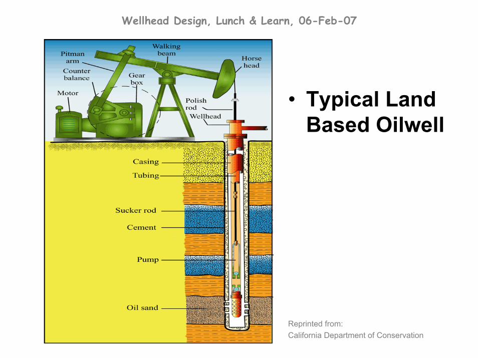
• Typical Land Based Oilwell
Reprinted from:California Department of Conservation

Wellhead Design, Lunch & Learn, 06-Feb-07
• Typical Land Based Drilling Rig
Reprinted from:California Department of Conservation
Wellhead Design, Lunch & Learn, 06-Feb-07
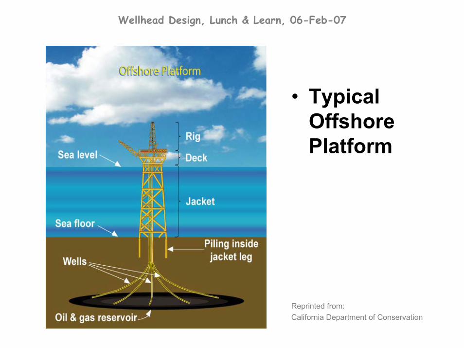
• Typical Offshore Platform
Reprinted from:California Department of Conservation
Wellhead Design, Lunch & Learn, 06-Feb-07

Wellhead Design, Lunch & Learn, 06-Feb-07
Wellhead Equipment for Exploration and Development

Wellhead Design, Lunch & Learn, 06-Feb-07
• Conventional Wellheads used for Exploration and Development Wells
• Unitized Wellheads used for Development Wells
• Mudline Equipment used for Development Wells, but generally run in Exploration Wells as contingency
• Production Equipment used for Development Wells
Wellhead Design, Lunch & Learn, 06-Feb-07
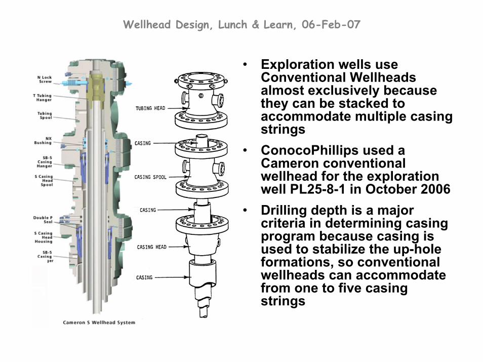
• Exploration wells use Conventional Wellheads almost exclusively because they can be stacked to accommodate multiple casing strings
• ConocoPhillips used a Cameron conventional wellhead for the exploration well PL25-8-1 in October 2006
• Drilling depth is a major criteria in determining casing program because casing is used to stabilize the up-hole formations, so conventional wellheads can accommodate from one to five casing strings

Wellhead Design, Lunch & Learn, 06-Feb-07
• Conventional Wellheads require nippling-up and nippling-down the BOP stack to install each section, which requires a lot of rig-time; rig-time is very expensive
• Typically low technology design options
• After use, Convention –al Wellhead spools can be easily separated, repaired, inspected, and re-used
Wellhead Design, Lunch & Learn, 06-Feb-07
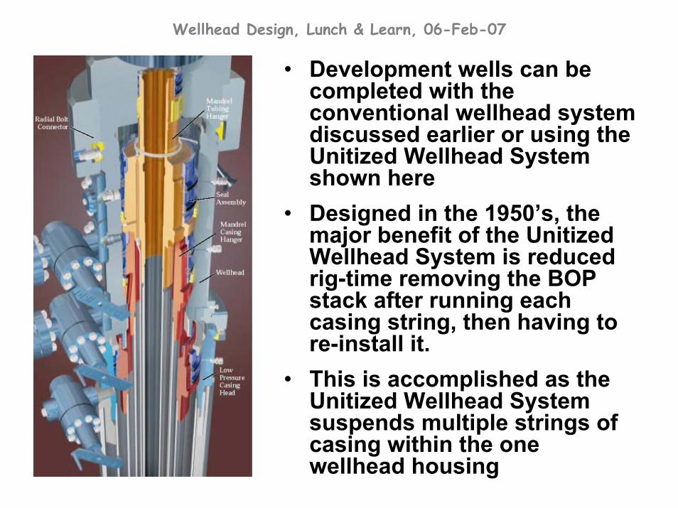
• Development wells can be completed with the conventional wellhead system discussed earlier or using the Unitized Wellhead System shown here
• Designed in the 1950’s, the major benefit of the Unitized Wellhead System is reduced rig-time removing the BOP stack after running each casing string, then having to re-install it.
• This is accomplished as the Unitized Wellhead System suspends multiple strings of casing within the one wellhead housing
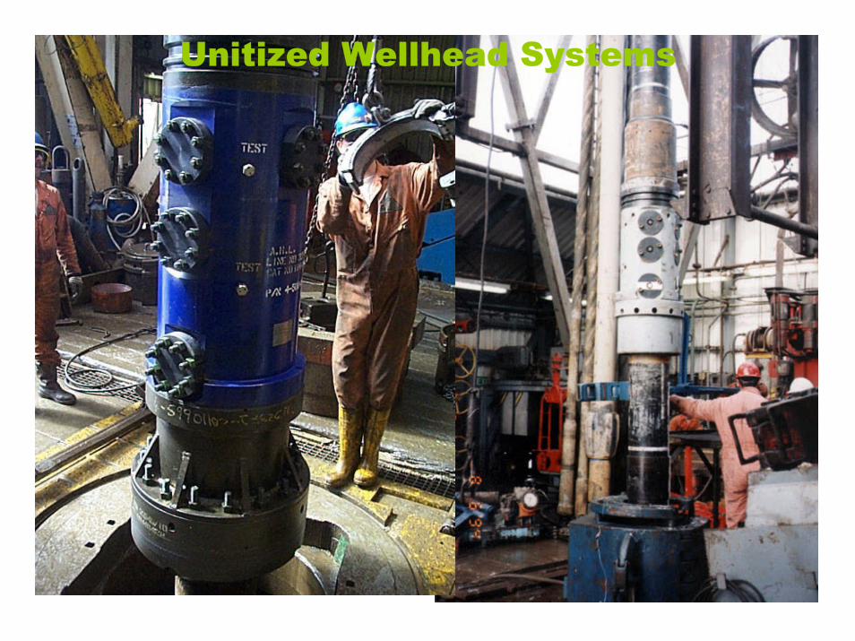
Unitized Wellhead Systems
Wellhead Design, Lunch & Learn, 06-Feb-07
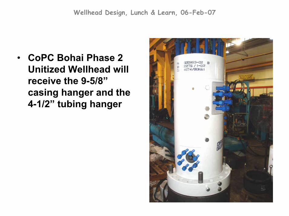
• CoPC Bohai Phase 2 Unitized Wellhead will receive the 9-5/8”casing hanger and the 4-1/2” tubing hanger

Wellhead Design, Lunch & Learn, 06-Feb-07
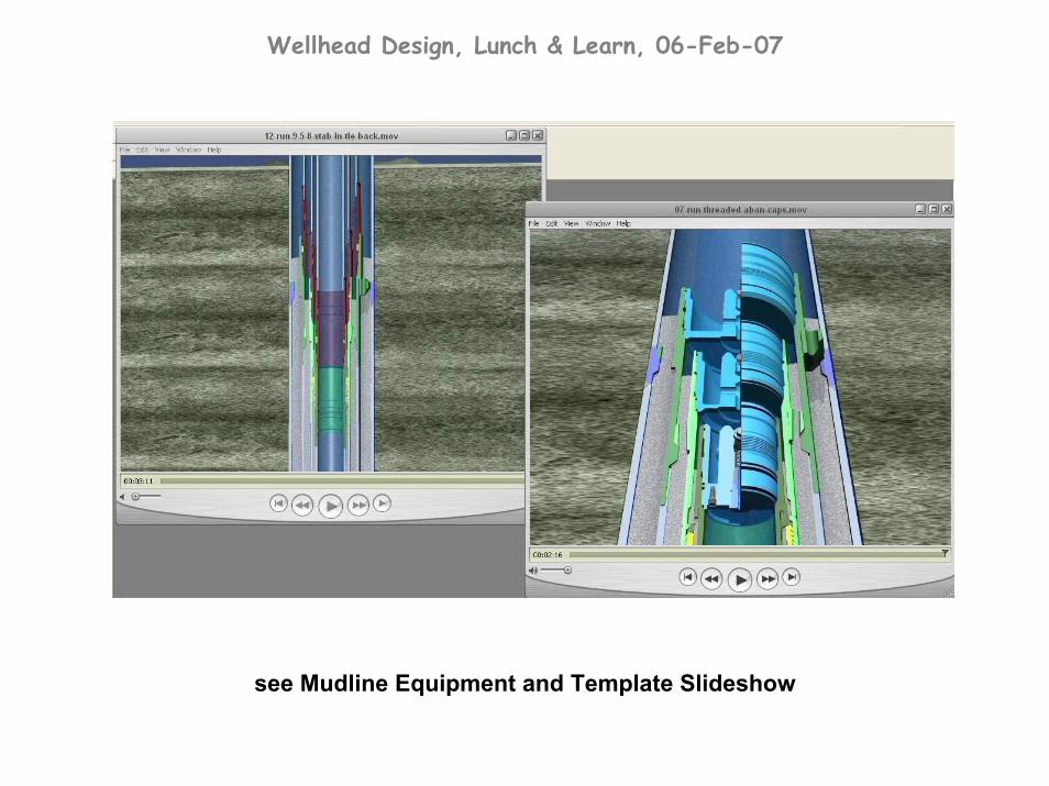
• Mudline Systems are used in both exploration and development wells and are designed for temporary abandonment and reconnect at a later time
• Used if exploration campaigns are expected to yield good shows of oil or if development of the oilfield may take several more months or years
• With the improved design of today’s Mudline Systems, they are almost universally used during exploratory drilling
Wellhead Design, Lunch & Learn, 06-Feb-07
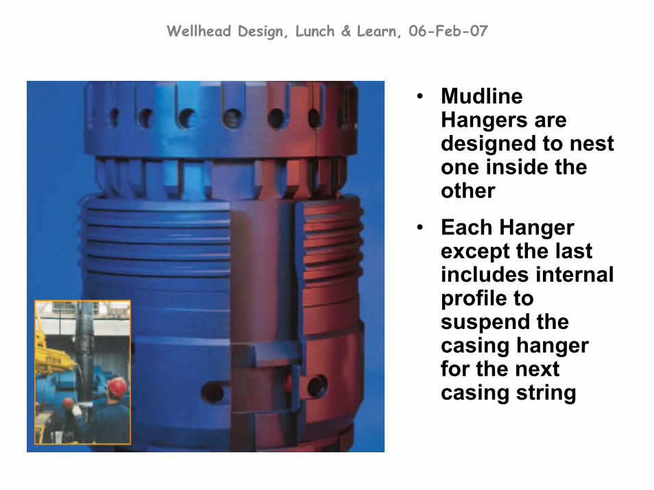
• Mudline Hangers are designed to nest one inside the other
• Each Hanger except the last includes internal profile to suspend the casing hanger for the next casing string

Wellhead Design, Lunch & Learn, 06-Feb-07
• Temporary Abandonment (TA) Caps are installed after drilling to isolate the annuli and hole bore for months or years until the platform is installed above
• The upper-most TA Cap is spaced out during drilling to be a couple metres above the mudline
• Tie-back hangers have seals to re-establish integrity with each casing string back to the platform
Wellhead Design, Lunch & Learn, 06-Feb-07
see Mudline Equipment and Template Slideshow

Wellhead Design, Lunch & Learn, 06-Feb-07
• Once the drilling has reached its total depth and production casing is in place, the operations that prepare the well for production is referred to as Completion.
• Completion includes displacement of drilling mud with completion fluid, perforating the casing, and installation of the production tubing.
• Finally, the Surface Production Equipment is installed which will control the flow of oil from the well during production.
• This flow control equipment is an assembly of valves known as the christmas tree.

Wellhead Design, Lunch & Learn, 06-Feb-07
• The christmas tree can include actuated valves (air or hydraulic), manual valves, and production chokes in order to the control flow of oil.
Pneumatic Actuated Master Valve
Manual Master Valve
Production Choke
CoPC Bohai Wellhead and Tree Assembly

Wellhead Design, Lunch & Learn, 06-Feb-07
There are numerous designs and arrangements for the production equipment.
Wellhead Design, Lunch & Learn, 06-Feb-07
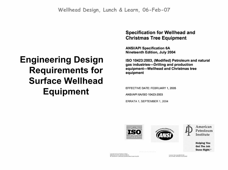
Engineering Design Requirements for Surface Wellhead
Equipment
Wellhead Design, Lunch & Learn, 06-Feb-07
American Petroleum Institute (API)
• established in 1919 when American oil companies worked together to standardize oil field equipment in order to provide more reliable supply to the country
• maintain more than 500 standards and recommended practices covering all segments of the oil and gas industry to promote use of interchangeable equipment and sound engineering practices
• license facilities that produce products that meet API standards, to monogram those products with the API logo
• API Specification 6A covers the standardization of valves and wellhead equipment and first appeared in 1961. The Nineteenth Edition is the current reference for manufacture and use of surface wellhead equipment.
• Scope of API 6A includes criteria for performance, design, material selection, testing, inspection, welding, marking, handling, storage, shipping, and documentation of the wellhead equipment.

Wellhead Design, Lunch & Learn, 06-Feb-07

Wellhead Design, Lunch & Learn, 06-Feb-07
API Design.
Design Methodology for pressure containing equipment is as described in ASME, Section VIII, Division 2, Appendix 4. Design allowable stresses are limited by the following criteria:
St = 0.83 * Sy and Sm = 2/3 * Sy
where,Sm = design stress intensity at W.P.St = maximum allowable general primary
membrane stress intensity at T.P.Sy = the mat’l specified min. yield strength
The theory of constant energy of distortion can also be used for design calculations for pressure containing equipment. Discontinuities and stress concentrations must be considered where applicable.
Wellhead Design, Lunch & Learn, 06-Feb-07
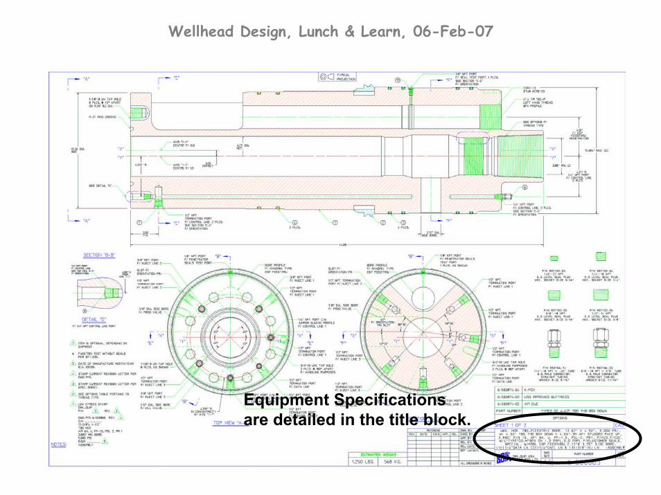
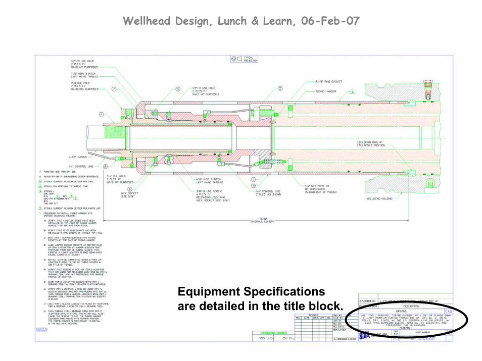
Equipment Specifications are detailed in the title block.
Wellhead Design, Lunch & Learn, 06-Feb-07
Equipment Specifications are detailed in the title block.

Wellhead Design, Lunch & Learn, 06-Feb-07
Temperature Ratings – equipment must be designed to operate in one or more of the specified temperature ratings per API 6A. The design must consider the effects of differential thermal expansion from temperature gradients which the equipment experiences in service.
Wellhead Design, Lunch & Learn, 06-Feb-07
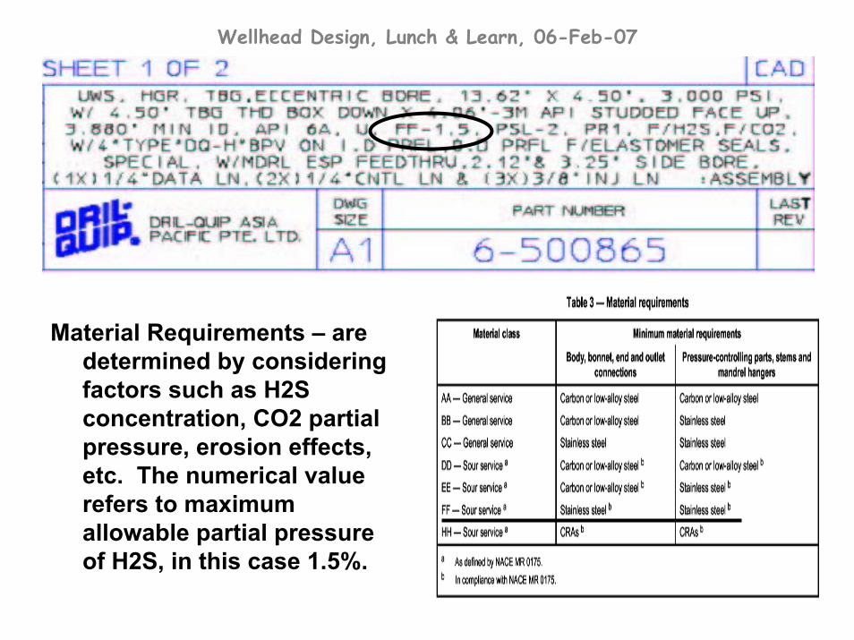
Material Requirements – are determined by considering factors such as H2S concentration, CO2 partial pressure, erosion effects, etc. The numerical value refers to maximum allowable partial pressure of H2S, in this case 1.5%.
Wellhead Design, Lunch & Learn, 06-Feb-07
Wellhead Design, Lunch & Learn, 06-Feb-07
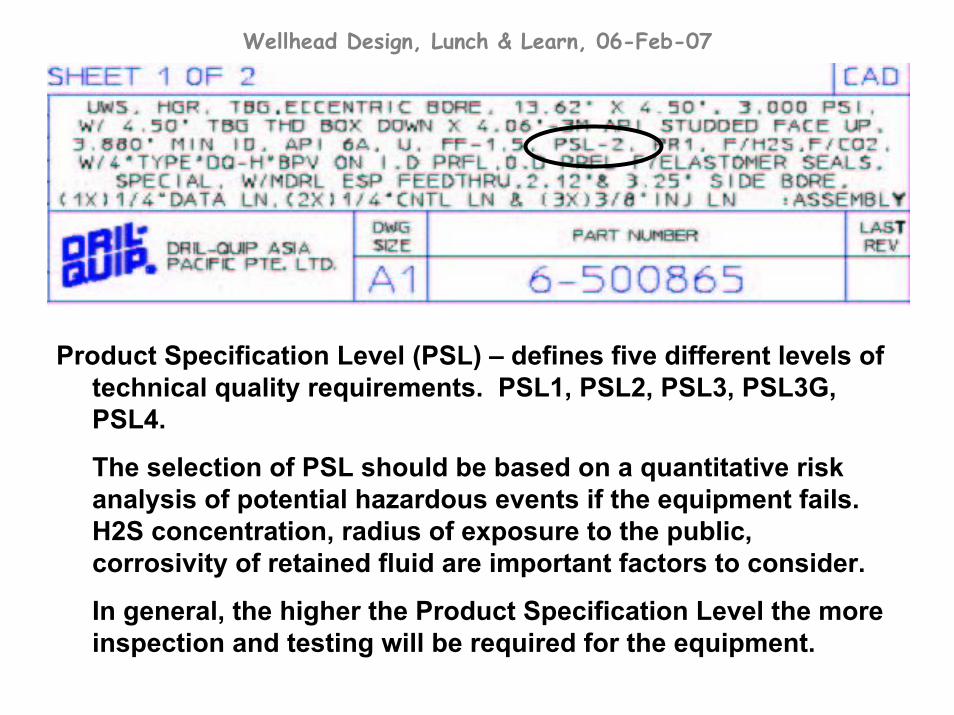
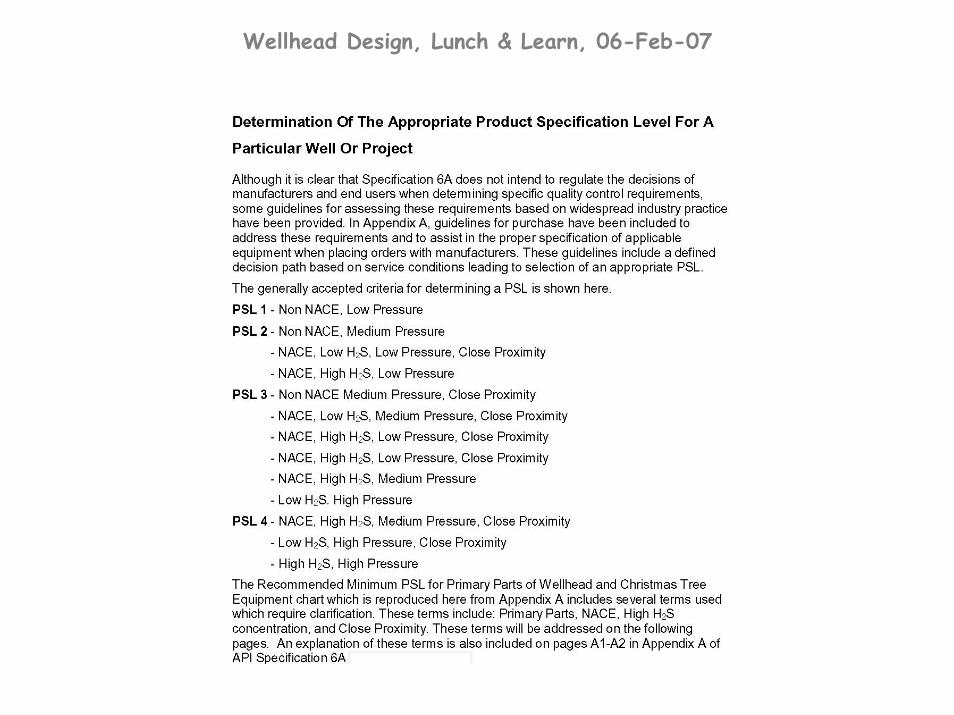
Product Specification Level (PSL) – defines five different levels of technical quality requirements. PSL1, PSL2, PSL3, PSL3G, PSL4.
The selection of PSL should be based on a quantitative risk analysis of potential hazardous events if the equipment fails. H2S concentration, radius of exposure to the public, corrosivity of retained fluid are important factors to consider.
In general, the higher the Product Specification Level the more inspection and testing will be required for the equipment.
Wellhead Design, Lunch & Learn, 06-Feb-07
Wellhead Design, Lunch & Learn, 06-Feb-07
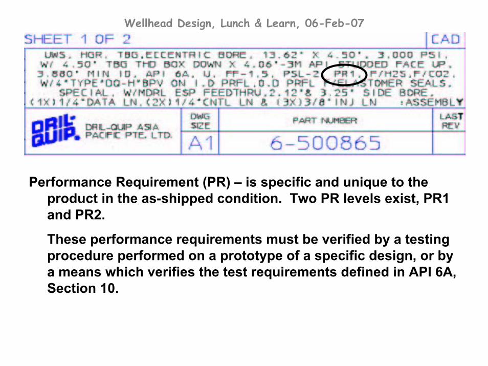
Performance Requirement (PR) – is specific and unique to the product in the as-shipped condition. Two PR levels exist, PR1 and PR2.
These performance requirements must be verified by a testing procedure performed on a prototype of a specific design, or by a means which verifies the test requirements defined in API 6A, Section 10.

Wellhead Design, Lunch & Learn, 06-Feb-07
Bohai Phase 2 Development
Wellhead Equipment

Wellhead Design, Lunch & Learn, 06-Feb-07
Design Objectives:
‘ Standardize the wellhead and tree components to the greatest extent practical considering the following factors:
a. interchangeability of components,b. minimizing spare part inventory,c. maintenance, andd. cost effectiveness.
• Minimize the aerial envelope of the wellhead and tree assembly in order to maximize the working clearance between wellheads and to ensure safe ingress/egress of the wellhead area.
(see 3D image of Wellhead decks)
• Use a basic design philosophy in order to choose reliable and well-proven equipment to reduce maintenance and workover costs.
• Wellheads must be Unitized type.

Wellhead Design, Lunch & Learn, 06-Feb-07
Production Well Water Injection Well Cuttings ReInjection Well
Wellhead Design, Lunch & Learn, 06-Feb-07
• The CoPC Bohai Wellhead System was designed with a unique horizontal production tree.
• A horizontal production tree allows complete access to the well bore without removing the tree. The well is produced from the side of the tubing hanger and flows horizontally through the master valve.
• Horizontal production trees are ideal on wells where frequent workovers are anticipated, such as Electric Submersible Pump (ESP) applications.

Wellhead Design, Lunch & Learn, 06-Feb-07
Conventional Wellhead and Tree
Assembly
Horizontal Wellhead and Tree Assembly