ICC Educational Session, Cable Accessory Didactic … Educational Session, Cable Accessory Didactic...
39
ICC Educational Session, Cable Accessory Didactic Matt Spalding October 20, 2010
Transcript of ICC Educational Session, Cable Accessory Didactic … Educational Session, Cable Accessory Didactic...

ICC Educational Session, Cable Accessory Didactic
Matt Spalding
October 20, 2010

Matt Spalding 20 October 2010 page 2 of 39
Cable System Applications
Energy- Grid to Residential Communication Service Providers (including under sea) Building Networks

Matt Spalding
Typical UG LV Cable Construction
20 October 2010 page 3 of 39
Remember: P-S-I
Conductor Carries Current Efficiently Copper (Cu) or Aluminum (Al) Different shapes: Concentric,
Compact, Compressed, Sectored (3/C)
Moisture Blocking Filler
Insulation Generally Inexpensive compared to MV Provides the 3 main requirements:
Mechanical Protection- conductor Environmental Seal- chemical attack Electrical Insulation- retains voltage
Materials include PE, XLPE, EPR, TP Typical Ratings: XHHW, THHN, TW, USE

Matt Spalding
Good Cable & Accessory System Balances Material Properties & Economics to Suit Application • Stranding Versus Solid: applies to conductor only
– Solid: non-vibration applications – Stranding: flexibility & vibration resistance
• Conductor or Connector (accessory) – Cost: aluminum is typically less expensive – Power required: higher power can drive towards copper – Environment: copper is usually more corrosion resistant & can tin coat
• Insulation: applies to cable & accessories – Toughness: direct buried, conduit, tray, drag, etc. – Flexibility: application, installation & seals – Environment: bulk material substrate & sealing medium (adhesive, mastic, gel,
grease or interference/grommet) • Chemical & biological: hydro carbons, fungus, acids, etc. • Temperature: low and/or high • Radiation: solar and nuclear
20 October 2010 page 4 of 39

Matt Spalding
MV Cable Systems: Must Address the LV Requirements plus High Electrical Stresses
• What is Electrical Stress? – Electrical Stress E is the force applied on a
medium to move a unit charge. – Electrical Stress E is the applied voltage
divided by the linear distance. – Air is an insulator under 21.6 kV/cm – Above this stress level air is a conductor and
not a very pleasant one with a lot of moving charges:
•Lightning is a good example.
20 October 2010 page 5 of 39
EV
d

Matt Spalding
• Electrical Stress requires a potential difference (voltage V ) but is dependent on the distance (D) that divides this potential:
20 October 2010 page 6 of 39
Electrical Stress- Voltage and Distance
20 kV
d=1cm
EkV
cm
2 0
1
E= 20 kV/ cm
20 kV
d=10cm
20 kV
d=10cm
EkV
cm
2 0
1 0
E= 2 kV/ cm
Electrical Stress calculations with the same voltage and different distances

Matt Spalding
Working Voltage and the stresses in LV through MV cable insulations • Dielectrics are classified by their breakdown and working voltages • Working voltage is the voltage that an insulation system can operate
at for a systems designed life • As the cable voltage class increases, the working voltage stress levels
increase significantly. This means that the cable system has less and less margin or tolerance for manufacturing defects & workmanship deficiencies.
20 October 2010 page 7 of 39
Cable Class Nominal Insulation Thickness
Typical Applied Voltage or Es
Operating Stress
600 V 60-110 mils 300V L-G 300/110=2.7 – 5 V/mil 15 kV 175-220 mils 8000 V 8000/175= 45.7 V/mil 25 kV 260 mils 14.4 kV 14400/260= 55.4 V/mil 35 kV 345 mils 20.2 kV 20200/345= 58.5 V/mil
Matt Spalding
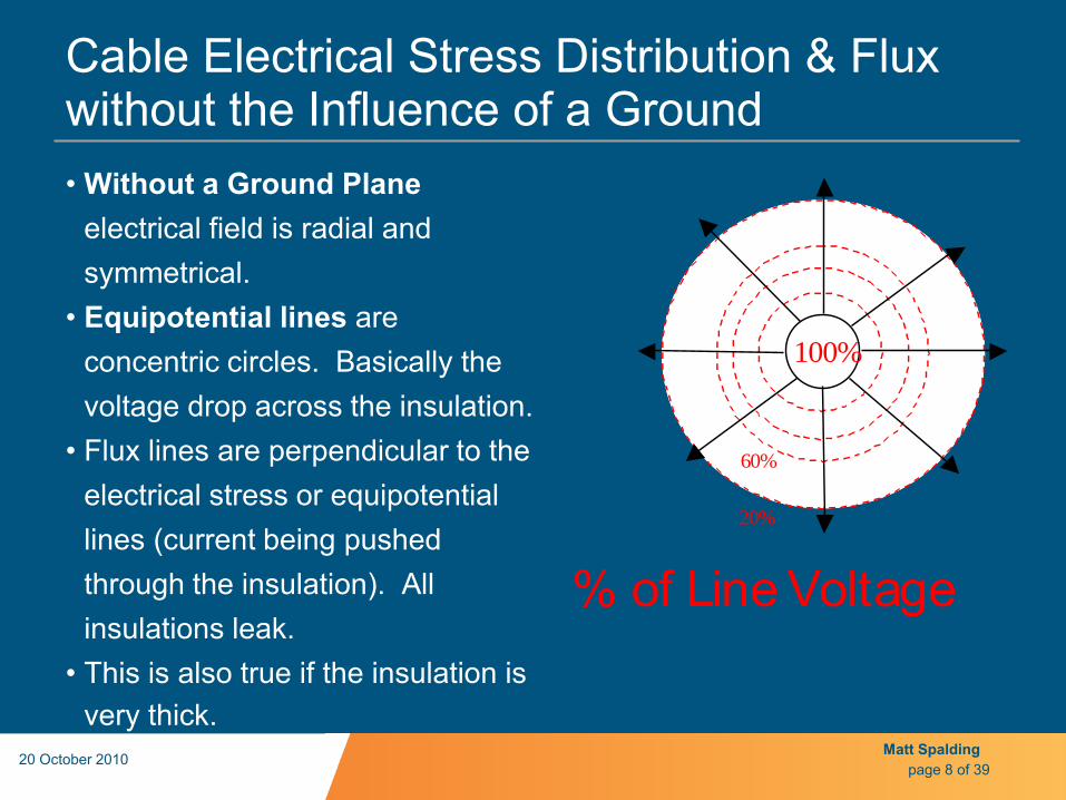
Cable Electrical Stress Distribution & Flux without the Influence of a Ground • Without a Ground Plane
electrical field is radial and symmetrical.
• Equipotential lines are concentric circles. Basically the voltage drop across the insulation.
• Flux lines are perpendicular to the electrical stress or equipotential lines (current being pushed through the insulation). All insulations leak.
• This is also true if the insulation is very thick.
20 October 2010 page 8 of 39
20%
60%
% of Line Voltage
100%

Matt Spalding
Cable Stress Distribution Influenced by a Ground Plane • Non Shielded Cable in a
conduit influences the electrical field non uniformly. Field lines bend to ground plane at contact area.
• The Equipotential lines are also bent and produce high potential difference over small distance = High Stress.
20 October 2010 page 9 of 39
60%
10%
Area of Very High Stress!
100%
Conduit
Non ShieldedCable
Matt Spalding
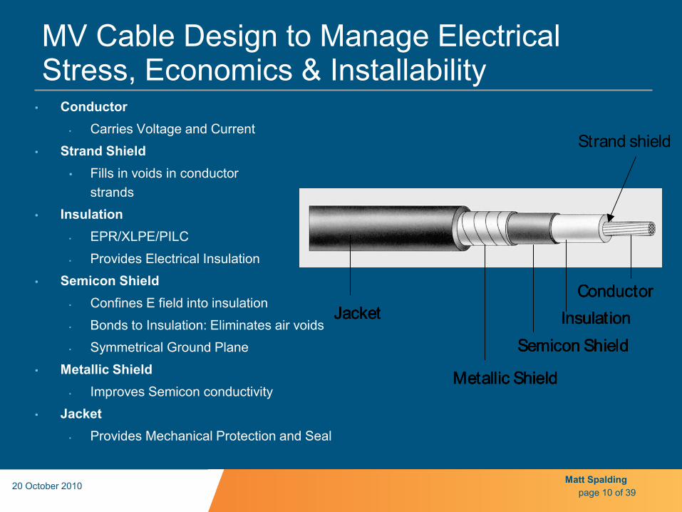
MV Cable Design to Manage Electrical Stress, Economics & Installability
• Conductor • Carries Voltage and Current
• Strand Shield • Fills in voids in conductor
strands • Insulation
• EPR/XLPE/PILC • Provides Electrical Insulation
• Semicon Shield • Confines E field into insulation • Bonds to Insulation: Eliminates air voids • Symmetrical Ground Plane
• Metallic Shield • Improves Semicon conductivity
• Jacket • Provides Mechanical Protection and Seal
20 October 2010
page 10 of 39
ConductorInsulation
Semicon Shield
Metallic Shield
JacketConductor
InsulationSemicon Shield
Metallic Shield
JacketConductor
InsulationSemicon Shield
Metallic Shield
Jacket InsulationSemicon Shield
Metallic Shield
Jacket
Strand shield

Matt Spalding
Why is MV Shielded Cable such a Clever Design? • The semicon shield places the
ground plane equally around the conductor
• Flux lines become symmetrical • Electrical Stress is reduced at
conduit contact • E field is contained in dielectric
insulation • Cable is safe to touch • Cable has symmetrical ground
path for leakage or fault currents
• Cable is compact for handling • Cable is economical to
manufacture and deploy • Cable system life meets
industry requirements 20 October 2010
page 11 of 39
Semicon
Insulation

Matt Spalding
Some Typical Cable Constructions
• Wire Shield or JCN • JCN has large wires and is
a Utility cable
• Metallic Tape Shielded • Usually EPR and an Industrial
or large feeder Utility • UniShield
• EPR Industrial cable with drain wires IN THE SHIELD- Shield is the Jacket
• LC Shielded Cable • Utility Premium EPR Cable
• 3/C Armor • Industrial Cable at Paper mills &
Large facilities
20 October 2010
page 12 of 39

Matt Spalding
So Since the Cable Engineering Design is so Clever, why are there problems in the Field?
• To splice & terminate the cable the first thing that must be done
is to mess up all of the great cable engineering
• Damage from transit, handling and installation allows the environment to access the cable’s interstices
• All organic materials degrade with stress. These can be temperature, radiation, chemical, mechanical & electrical, especially if they are exposed to extremes or long durations.
• Great care must be taken during manufacturing such as: – Compound formulations, quality & cleanliness – Extrusion speeds, temperatures (both extrusion & curing) – Take up & spooling
• Same is true for field working conditions. Importance increases with the cable system voltage
20 October 2010 page 13 of 39

Matt Spalding
Preparation & Workmanship
• End cuts- Square & uniform to allow proper tool depth setting • Tool setting- Knowledge & skill to select, set & use tools properly
– Right dies – Right number, location and application of crimps – Stripping tool set-up
• Conductor damage issues- typically longitudinal scores are not an issue, but any circumferential scores can cause the conductor to break with cycling
• Cleanliness- contamination creates failures & as voltage stress increases so does the degree of cleanliness (and good cable preparation or stripping)
• Checking connector & accessory match-right product for the right applications 20 October 2010
page 14 of 39

Matt Spalding
Good Cable Accessory Design Considerations • Sealing: conductor, jacket & body (pressure retention for PILC &
some polymer systems) • Weathering & environment stable: includes chemical, heat &
biological • Stable material properties that are compatible with the cable system
materials • Good thermal design: minimal trapped air, uniform and stable
interfacial pressure, & no cable choke points • Repeatable installation by trained workforce in the environments
required • Economical
20 October 2010
page 15 of 39

Matt Spalding
Terminations Design Requirements & Definitions
• Design requirements: – Terminates the insulation shield of a power cable – Provides tracking and erosion resistance – Provides a environmental seal
• Application definitions: – Device fitted to the end of a cable to ensure electrical connection
with other parts of the system and to maintain the insulation up to the point of connection.
– Indoor termination: Termination intended for use where it is not exposed to either solar radiation or weathering.
– Outdoor termination: Termination intended for use where it is exposed to solar radiation or weathering or both.
20 October 2010 page 16 of 39

Matt Spalding
Termination Design & Important Terminology
• Expected life-time > 40 years. • Must meet relevant standard • IEEE 48.
• Easy, reproducible field installation.
• Termination lug • Lug to meet relevant
specification, (ANSI 119.4)
• Stress grading • Axial and radial stress.
max. E-stress of the cable. • break-down stress in air.
20 October 2010 page 17 of 39
•Dry Arc distance. •In accordance with national / international standards.
•Creepage distance. •In accordance to pollution levels.
•Environment •Track & erosion resistant material i. e. ASTM D2703. •Low leakage current under humidity •Low water absorption
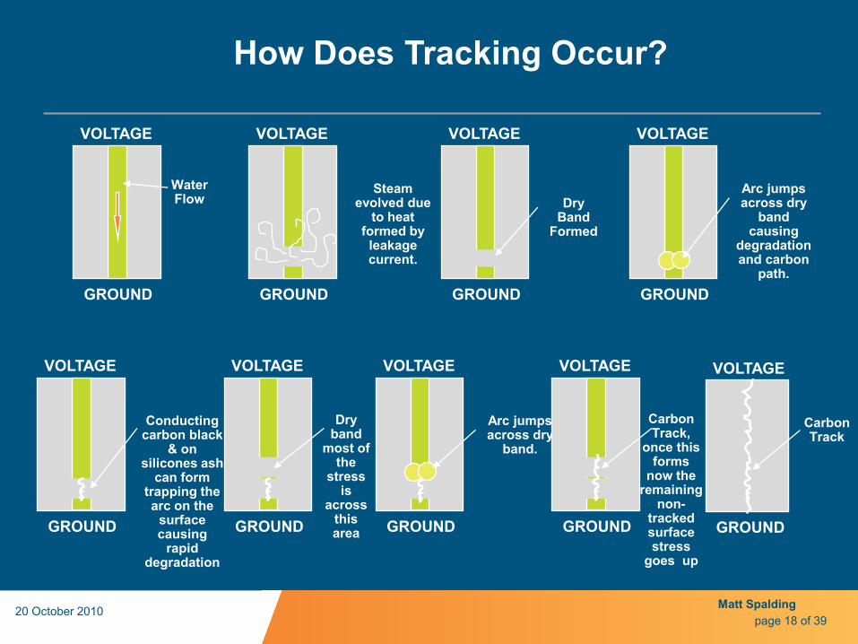
VOLTAGE
GROUND
Conducting carbon black
& on silicones ash
can form trapping the arc on the
surface causing
rapid degradation
VOLTAGE
GROUND
Dry band
most of the
stress is
across this area
VOLTAGE
GROUND
Arc jumps across dry
band.
VOLTAGE
GROUND
Carbon Track,
once this forms
now the remaining
non-tracked surface stress
goes up
VOLTAGE
GROUND
Carbon Track
VOLTAGE
GROUND
Water Flow
VOLTAGE
GROUND
Arc jumps across dry
band causing
degradation and carbon
path.
VOLTAGE
GROUND
Steam evolved due
to heat formed by
leakage current.
VOLTAGE
GROUND
Dry Band
Formed
How Does Tracking Occur?
page 18 of 39 20 October 2010 Matt Spalding
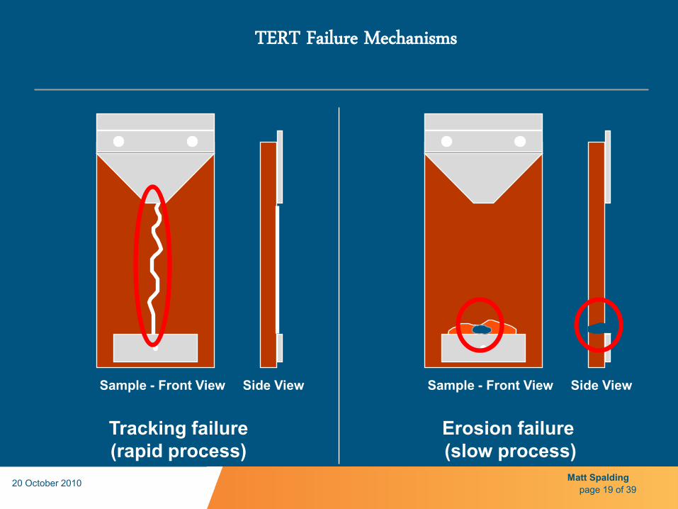
Tracking failure (rapid process)
Erosion failure (slow process)
Sample - Front View Side View Sample - Front View Side View
TERT Failure Mechanisms
page 19 of 39 20 October 2010 Matt Spalding

page 20 of 39 20 October 2010 Matt Spalding

EXAMPLE OF TRACKING
page 21 of 39 20 October 2010 Matt Spalding

Matt Spalding
Surface properties...ASTM D2303 inclined plane..looks for tracking, flame failure & erosion rate
Puncture properties..tested as installed..do not rely on material tests alone
Salt Fog under energized conditions
Multiple Stress Testing
It is important to think about the environments materials are exposed to when determining the required testing protocols
Outdoor Polymer Material Testing
page 22 of 39 20 October 2010

Creepage distance selection guide (IEC 815)
Creepage ESDD mg/cm2 Pollution Level
Class 1 16mm/kV 0.03 – 0.06 Light
Class 2 20mm/kV 0.1 – 0.2 Medium
Class 3 25mm/kV 0.3 – 0.6 Heavy
Class 4 31mm/kV >0.6 Very Heavy
page 23 of 39 20 October 2010 Matt Spalding

Matt Spalding
Cable & Accessory Material Characteristics: Heat Transfer
• Conduction • Convection • Radiation
20 October 2010 page 24 of 39
Thermal Conductivities at 32F
Materialk
W/mKCopper 388
Lead 35
Silicone Oil 0.300
EPDM Rubber 0.180
Air 0.024

Matt Spalding
Conductor & Insulation Thermal Characteristics
Elo
gati
on
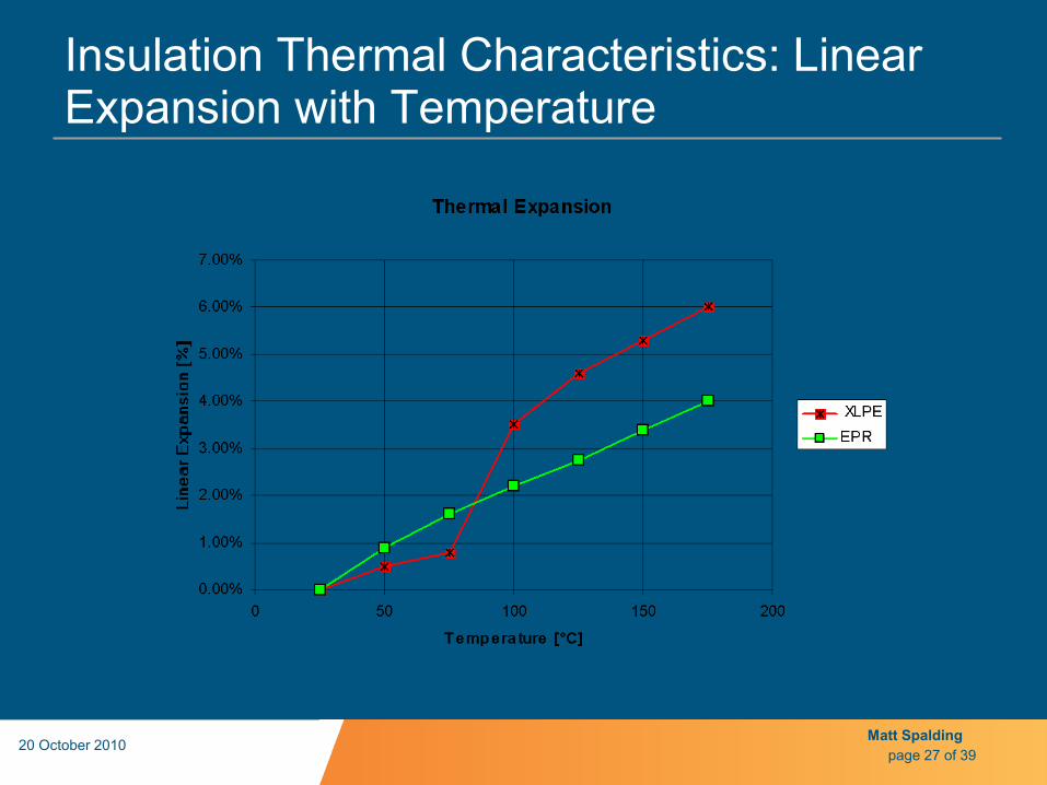
• Average Coefficient of Linear Expansion: a (10-6/ oC) Aluminum 23 Copper 17 Steel 11 D l = al DT DV = 3aV DT • Average Coefficient of Linear Expansion: a (10-6/ oC) XLPE 100-180 EPDM 80 • Load and emergency operating currents can cause the cable to
expand up to 12%.
page 25 of 39 20 October 2010

Matt Spalding
Insulation Thermal Characteristics: Volume Expansion with Temperature
20 October 2010 page 26 of 39
Matt Spalding
Insulation Thermal Characteristics: Linear Expansion with Temperature
20 October 2010 page 27 of 39

Matt Spalding
Cable Accessory Considerations because of Volume & Longitudinal Thermal Expansion • Are key cutback dimensions going to be affected?
– Semi-con cutback with stress management – Connector shielding or faraday cage – Cable and cable jacket sealing
• Will tension set or other basic material property changes affect original design performance?
• Material tension set characteristics can deteriorate dielectric interfacial pressure & sealing, thus the system performance
• Other material properties deterioration can have similar performance impacts
20 October 2010
page 28 of 39
Matt Spalding
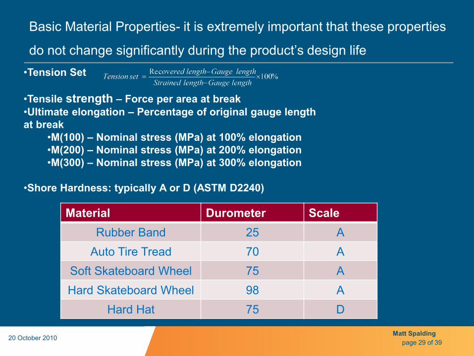
Basic Material Properties- it is extremely important that these properties
do not change significantly during the product’s design life
20 October 2010 page 29 of 39
•Tension Set
•Tensile strength – Force per area at break •Ultimate elongation – Percentage of original gauge length at break
•M(100) – Nominal stress (MPa) at 100% elongation •M(200) – Nominal stress (MPa) at 200% elongation •M(300) – Nominal stress (MPa) at 300% elongation
•Shore Hardness: typically A or D (ASTM D2240)
Material Durometer Scale Rubber Band 25 A
Auto Tire Tread 70 A Soft Skateboard Wheel 75 A Hard Skateboard Wheel 98 A
Hard Hat 75 D

Matt Spalding
How are Splice System Insulations Affected by Heat? • Hot connectors or overloading increases the splice cable temperature
above the glass transition temperature of XLPE • Cable insulation softens, allowing permanent profile deformation • Splice body naturally resists the expansion of the cable, which extrudes
the cable insulation away from the splice body • Cable insulation softens, allowing permanent profile deformation • Insulation life, physical, and electrical properties rapidly decrease with
increasing operating temperatures • The deteriorating physical properties reduce the splice bodies
compressive force on the substrate cable insulation • The permanent deformation of the cable insulation reduces the splice
body’s compressive force on the cable insulation
20 October 2010 page 30 of 39

Matt Spalding
Example of Cable Deformation after Load Cycling
20 October 2010 page 31 of 39

Matt Spalding
Accessory to Cable Interfacial Pressure after One Load Cycle
20 October 2010 page 32 of 39

Matt Spalding
Latest Generation Materials & Designs are Addressing many of the Historical Issues • TR-XLPE & EPR
– Must keep in mind that EPR leaks more current than XLPE for economic considerations
• Strand blocking to prevent moisture migration • Linear low density polyethylene: tough & flexible jackets • Accessory designs:
– Better environmental sealing – Uniform geometries eliminating many of the cable choke points – New materials such as LSR allowing more flexibility & easier
installaion – Air elimination or minimization around connectors to avoid the oven
affect • Shear bolt connectors
20 October 2010 page 33 of 39

Matt Spalding
Issues with Tolerances & Thermo Mechanical • Longitudinal movement, outside of things like faraday cages or
geometric stress control, even can cause body to move toward smaller conductor side in size transitions
• Grease required to pass initial qualification? – What is long-term stability of grease? – Require qualification without grease?
• Cable & accessory manufacturing tolerances, variability & drift • Designs that allow more tolerance for real world installations • Insulation shrinkback • General chemical & temperature material property changes
– Elasticity – Tension Set – De-polymerization
20 October 2010 page 34 of 39

Matt Spalding
Don’t the Accessory Standards such as IEEE 48 & 404 and ANSI 386 Guarantee that Cable Accessories will Perform?
l Std IEEE 404-1993 section 5.3 states:
“The joint shall be designed for operating with the conductor and connector within the
joint at the same maximum temperature limitations as those for the conductors of the
cables being joined”
• Smallest conductor size in use range. • No requirement for conductor type. • No requirement for insulation type. • No requirement for thermal shock. • No requirement for product range testing. • No requirement for connector type. • 386 for Elbows: completely different test levels & load cycling
requirements?
20 October 2010 page 35 of 39

Matt Spalding
Product Range Testing
• Can qualify by product line by testing only one kit out of the entire series.
• Larger splice bodies take longer to reach cable operating temperatures, thus exert more pressure on substrate cable insulation.
• During cooling cycles, the conductor transfers heat away from the cable insulation rapidly, weakening the interface
• Smaller diameter cables have less electrical stress on the accessory to cable interface and more on the conductor shield
• High end of accessory range has more cable insulation or termination surface stress and the accessory insulation is less because of the larger substrate
20 October 2010 page 36 of 39

Matt Spalding
What is Thermal Shock and Why is it Important • Thermal shock occurs when the cable is running hot and is then
submersed water. • Typically occurs during the summer:
– Hot day with high loads from air conditioners. – Heavy afternoon downpour and thunderstorm. – Vaults fill or soil becomes saturated rapidly with water. – Rapid temperature change causes seals to fail.
• Sealing in general, especially long-term should be looked at closely for all designs.
• LV ANSI tests have thermal shock included
20 October 2010 page 37 of 39

Matt Spalding
Connector Evaluation Specifically to the System (Cable Type & Accessory) is Critical • Aluminum connectors can be the weak link in the splice system. • Air pockets exacerbate the problem by thermally insulating the
connector and creating an “oven” affect • Thermal cycles and high temperatures accelerate creep. • Thermal runaway is very common. • Strand fill is problematic to make good connections • Workmanship is often deficient:
– Wire brushing – Tool & die calibration – Proper indents & installation method, ie. Start from the center and
work out to avoid loosing crimps in the alternate order
20 October 2010 page 38 of 39

Matt Spalding
Summary of the Additional Test Requirements Needed
• Test largest and smallest cable diameter in product use range • Require testing on Aluminum, XLPE cable • Require a test similar to ANSI C119.1, Section 4.3.10 • Better long-term seal tests are needed • After test cable and connector inspection • Criteria for post test pass/fail dimensional changes • Requirements to test on specialized designs such as strand-fill • 386 alignment with 404? • Material property changes, especially after thermal & environmental
exposure (UV, chemicals, mechanical & biological)
20 October 2010 page 39 of 39