HydroLink2 Supervisory Control Panel - Application and ...chiller with the least amount of run time...
78
HydroLink2 Supervisory Control Panel - Application and Troubleshooting Guide HydroLink2 Supervisory Control Panel Application and Troubleshooting Guide For use in all equipment utilizing the HydroLink2 Aurora Control Link2 Supervisory Control Panel - Application and AG1571EW 07/19
Transcript of HydroLink2 Supervisory Control Panel - Application and ...chiller with the least amount of run time...

Hyd
roLi
nk2
Sup
ervi
sory
Con
trol P
anel
- A
pplic
atio
n an
d Tr
oubl
esho
otin
g G
uide
HydroLink2 Supervisory Control PanelApplication and Troubleshooting Guide
For use in all equipment utilizing the HydroLink2 Aurora Control
Link
2 S
uper
viso
ry C
ontro
l Pan
el -
App
licat
ion
and
AG1571EW 07/19


HYDROLINK2 AURORA SUPERVISORY CONTROL PANEL APPLICATION GUIDE
Table of Contents
Introduction . . . . . . . . . . . . . . . . . . . . . . . . . . . . . . . . . . . . . . . . . . . . . . . . . . . . . . . . . . . . . . . . . . . . . .4
HydroLink2 Aurora Supervisory Control Features . . . . . . . . . . . . . . . . . . . . . . . . . . . . . . . . . . . . . 5
Staging Description . . . . . . . . . . . . . . . . . . . . . . . . . . . . . . . . . . . . . . . . . . . . . . . . . . . . . . . . . . . . . . . 8
HSC Installation Requirements . . . . . . . . . . . . . . . . . . . . . . . . . . . . . . . . . . . . . . . . . . . . . . . . . . . . . 9
Mounting Details . . . . . . . . . . . . . . . . . . . . . . . . . . . . . . . . . . . . . . . . . . . . . . . . . . . . . . . . . . . . . . . . . . 9
Electrical Requirements . . . . . . . . . . . . . . . . . . . . . . . . . . . . . . . . . . . . . . . . . . . . . . . . . . . . . . . . . . 10
HSC Wiring Requirements . . . . . . . . . . . . . . . . . . . . . . . . . . . . . . . . . . . . . . . . . . . . . . . . . . . . . . . . 10
Field Wiring . . . . . . . . . . . . . . . . . . . . . . . . . . . . . . . . . . . . . . . . . . . . . . . . . . . . . . . . . . . . . . . . . . . . . .11
HMI Screens . . . . . . . . . . . . . . . . . . . . . . . . . . . . . . . . . . . . . . . . . . . . . . . . . . . . . . . . . . . . . . . . . . . . . 12
HMI Screens Layout . . . . . . . . . . . . . . . . . . . . . . . . . . . . . . . . . . . . . . . . . . . . . . . . . . . . . . . . . . . . . .29
Change HSC Network IP Address . . . . . . . . . . . . . . . . . . . . . . . . . . . . . . . . . . . . . . . . . . . . . . . . . .30
Powering on HMI. . . . . . . . . . . . . . . . . . . . . . . . . . . . . . . . . . . . . . . . . . . . . . . . . . . . . . . . . . . . . . . . . 32
Login Screen (Pre Factory Tech Startup) First Time Connecting. . . . . . . . . . . . . . . . . . . . . . .33
Application Examples . . . . . . . . . . . . . . . . . . . . . . . . . . . . . . . . . . . . . . . . . . . . . . . . . . . . . . . . . . . .34
Four Pipe Standard Header Rack with Fixed Capacity Scroll Dedicated Chiller . . . . . . . . . .34
Four Pipe Reversing Header Rack with Fixed Capacity Scroll Dedicated Chiller . . . . . . . . 40
Four Pipe Standard Header Rack with Fixed Capacity Scroll Reversible Chiller . . . . . . . . . .46
Six Pipe Dedicated Header Rack with Reversible Chiller . . . . . . . . . . . . . . . . . . . . . . . . . . . . . . 52
Six Pipe Standard Header Rack with Fixed Capacity Scroll Dedicated Chiller . . . . . . . . . . .58
HydroLink2 Aurora Control Codes . . . . . . . . . . . . . . . . . . . . . . . . . . . . . . . . . . . . . . . . . . . . . . . . .64
HMI Reloading/Rebooting Procedure . . . . . . . . . . . . . . . . . . . . . . . . . . . . . . . . . . . . . . . . . . . . . .65
BACnet Pointslists . . . . . . . . . . . . . . . . . . . . . . . . . . . . . . . . . . . . . . . . . . . . . . . . . . . . . . . . . . . . . . .67
Wiring Diagram. . . . . . . . . . . . . . . . . . . . . . . . . . . . . . . . . . . . . . . . . . . . . . . . . . . . . . . . . . . . . . . . . . 73
Port Layout . . . . . . . . . . . . . . . . . . . . . . . . . . . . . . . . . . . . . . . . . . . . . . . . . . . . . . . . . . . . . . . . . . . . . 74
System Configuration . . . . . . . . . . . . . . . . . . . . . . . . . . . . . . . . . . . . . . . . . . . . . . . . . . . . . . . . . . . . 75
Revision Guide. . . . . . . . . . . . . . . . . . . . . . . . . . . . . . . . . . . . . . . . . . . . . . . . . . . . . . . . . . . . . . . . . . .76

4
HYDROLINK2 AURORA SUPERVISORY CONTROL PANEL APPLICATION GUIDE
The HydroLink 2 Supervisory Control Panel is a Niagara AX based control, designed to automate the chiller assembly with
an application specific supervisory control. By using an application specific control, optimal plant room management can
be obtained to insure proper operation and easier servicing with a turnkey solution. It features a Niagara AX based control
with its own I/O and a color touchscreen tablet as a user interface. Turn-key custom programming of the Supervisory
Control will be provided based upon your specific requirements for the whole chiller plant to manage the chillers and as an
option, the pumps and other hydronic specialties.
Benefits of the HydroLink2 Supervisory control:
• It is a powerful and flexible Niagara AX software platform based controller.
• Optimal supervisory control programming to meet your specific site specifications.
• Customized integration of mechanical room components such as variable speed pumps and other hydronic specialties
of the plant room into the site BAS.
• Guaranteed compatibility of the Supervisory Controller with the Unit Controllers.
• The sophistication of the Niagara based control allows better equipment support and servicing. Customer benefits
from our experience in providing custom Supervisory Controllers.
• Improved system visibility from the BAS.
The HSC Panel is the ideal match to manage your complete chiller mechanical room.
Introduction
HydroLink2 Supervisory ControlHyHydrdroLoLinink2k2 Supervisory Control

5
HYDROLINK2 AURORA SUPERVISORY CONTROL PANEL APPLICATION GUIDE
HydroLink2 Supervisory Control Features• HydroLink 2 Control uses the powerful NIAGARA
software platform.
• Internal power supply and a 120Vac convenience outlet
are built into the cabinet.
• Over 2 sq. ft. [0.19 m2 of control mounting area for
custom controls such as relays or transducers.
• Provides for a customized programmed chiller plant
controller.
• Internal mounted and wired 10” Touch Screen tablet for
interfacing with Supervisory Controller. HydroLink2 Supervisory Controller
utlet
nt
et for HydroLink2 Supervisory Controller
115Vac to 24 Vac Transformer
Optional 115Vac Power
Outlet
6
HYDROLINK2 AURORA SUPERVISORY CONTROL PANEL APPLICATION GUIDE
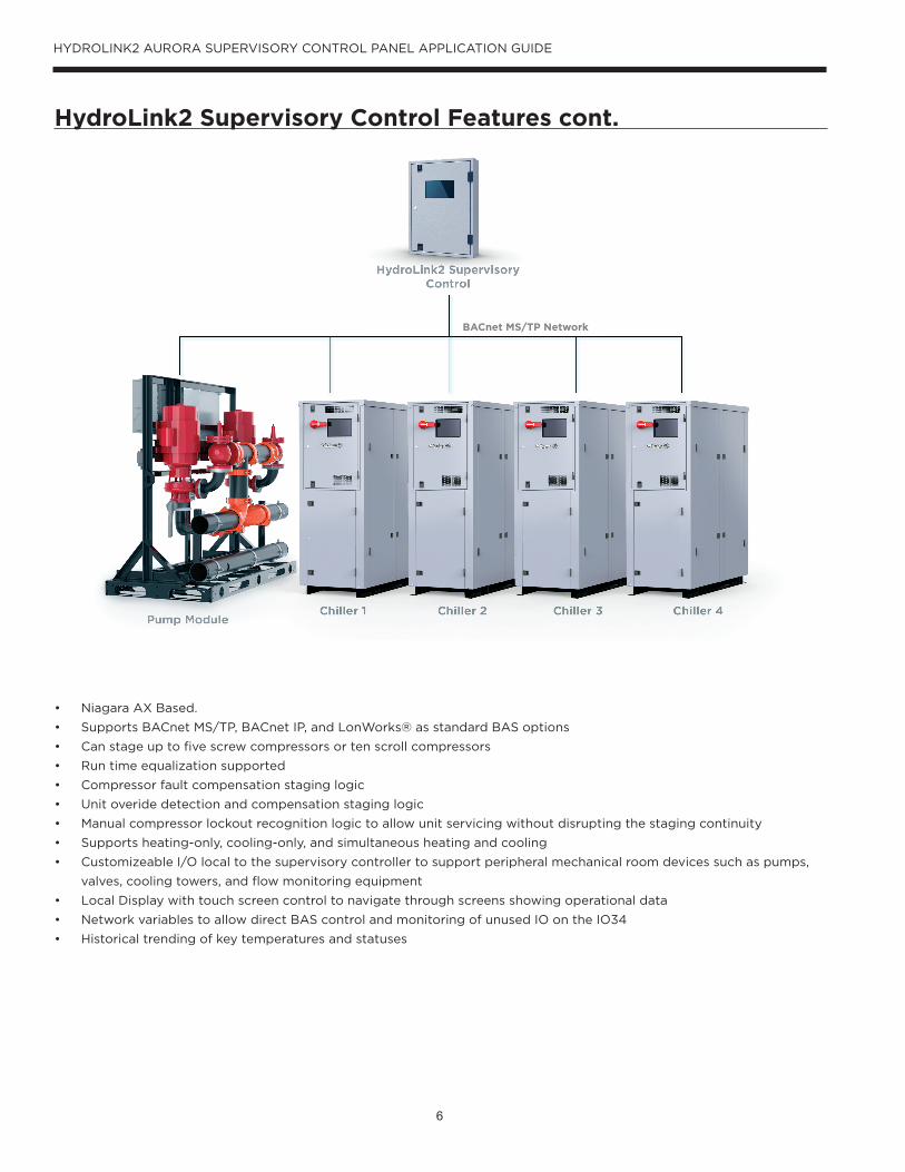
HydroLink2 Supervisory Control Features cont.
BACnet MS/TP Network
• Niagara AX Based.
• Supports BACnet MS/TP, BACnet IP, and LonWorks® as standard BAS options
• Can stage up to five screw compressors or ten scroll compressors
• Run time equalization supported
• Compressor fault compensation staging logic
• Unit overide detection and compensation staging logic
• Manual compressor lockout recognition logic to allow unit servicing without disrupting the staging continuity
• Supports heating-only, cooling-only, and simultaneous heating and cooling
• Customizeable I/O local to the supervisory controller to support peripheral mechanical room devices such as pumps,
valves, cooling towers, and flow monitoring equipment
• Local Display with touch screen control to navigate through screens showing operational data
• Network variables to allow direct BAS control and monitoring of unused IO on the IO34
• Historical trending of key temperatures and statuses

7
HYDROLINK2 AURORA SUPERVISORY CONTROL PANEL APPLICATION GUIDE
HydroLink2 Supervisory Control Features cont.
The HydroLink Supervisory Control (HSC) is scazlable from two to five dual scroll Reversible Chillers or two to five single
screw compressor chillers. Heating and cooling mode are both supported. The control algorithm is a PID based algorithm
that operates a sequencing logic which determines which chiller is next in the sequence based on unit run time, local
overrides, BAS overrides, as well as unit fault status.
The PID compares the controlled water temperature to the desired temperature (Set Point) and the controlled water
temperature of the previous few minutes in order to generate a demand percentage for capacity. The sequencing logic will
respond to capacity demand changes by starting or stopping a compressor to a chiller. If the demand is increasing and
crosses a threshold for starting another compressor, the sequencing logic will do one of two things: If a chiller is running
only one compressor, the second compressor will be started. Otherwise, the logic will select a non-running and non-faulted
chiller with the least amount of run time and issue a compressor command to that chiller. If the demand is decreasing and
crosses a threshold for stopping a compressor, the sequencing logic will do one of two things: If a chiller is running only one
compressor, that compressor will be stopped. Otherwise, the logic will select from the running chillers the chiller with the
highest run time and remove one of the compressor calls.
The supervisory controller can be programmed for communications to virtually any type of BAS. BACnet is the standard
option for the supervisor’s BAS connection. Peripheral devices such as pumps and other chiller plant equipment can—on a
custom basis—be added to the control of the supervisor. Contact the manufacturer for more info.

8
HYDROLINK2 AURORA SUPERVISORY CONTROL PANEL APPLICATION GUIDE
Staging Description
OverviewThe HydroLink 2 Supervisory Control (HSC), has staging software that can be enabled or disabled by a single binary (two-
state) variable named “SystemEnable.” The mode of operation is selected by a multi-state variable called “SystemMode”
which indicates to the program which setpoints (heating or cooling) and mode of operation will be used. The HSC selected
mode is communicated to each individual unit controller. If the system configuration includes a six-pipe header rack,
then the capabilities of simultaneous heating and cooling will be functional. If a simultaneous mode is selected, the unit
controllers will modulate the three-way water valves on the header rack to blend the source fluid with the “secondary load”
fluid to maintain a temperature setpoint while the HSC will stage on and off the individual compressors to maintain the
“primary load” fluid temperature. If the piping configuration is not a six-pipe, then simultaneous heating and cooling modes
will not function. In the heating-only or cooling-only modes, the HSC will stage compressors on or off to maintain the
desired header rack leaving water temperature.
Fixed Speed Scroll CompressorsThe HSC will stage units based on:
• Leaving water temperature
• Compressor fault status
• Unit run time
The staging logic uses a specialized PID control algorithm that is designed to control stepped capacity systems. The
control algorithm not only has the standard proportional and integral features, but also a derivative feature that is used to
recognize short and long term load responses to capacity changes and to ambient temperature influences. This feature
improves the capacity-to-load matching accuracy and is predictive. The output range of the PID control is 0% to 100%. This
range is divided into equal segments to provide turn-on and turn-off thresholds for the compressors. If the option selected
were a 4 compressor stager, then the first compressor would be turned on when the PID output reaches 25%. The second
at 50%, the third at 75% and the fourth at 100%. For staging down, the first ‘stop’ command would be issued at 75%, the
second at 50%, the third at 25%, and the fourth at 0% output of the PID. When a start or a stop command is issued, a
delay timer is initiated. While the delay timer is active, the PID is ‘frozen’ at the current value so that the system capacity
change can begin to take effect. When the timer has expired, the derivative portion of the PID will be able to freeze the
PID output if the water temperature is moving toward the setpoint at a satisfactory rate—staging up or down. This will
reduce the likelihood of engaging or dropping too many stages and causing severe overshoot of setpoint. When staging
up, the staging logic will select the next unit based on unit cumulative run time. If there’s a unit with only one compressor
commanded on, then the second compressor in that unit will be the next one to be turned on. Otherwise, the staging logic
will issue a compressor call to the non-running unit that has the least amount of runtime and shows no compressor faults
or lock-outs. Likewise, when staging down, if there’s a unit with only one compressor running, that compressor will be the
next one off. Otherwise, the staging logic will remove a compressor call from the running unit with the most run time. The
staging logic recognizes a manually locked-out compressor and will remove it from the staging sequence to avoid ‘dead
spots’ in the staging response. An adjustable deadband is used to reduce the on/off cycling of compressors when the
controlled water temperature is reasonably close to the set point.

9
HYDROLINK2 AURORA SUPERVISORY CONTROL PANEL APPLICATION GUIDE
Mounting Details
Mount HSC Panel indoors and within close proximity to the mechanical room that houses the chillers and devices it
controls. The HSC Panel must be free and clear of any obstructions that prevent access to and within the enclosure. The
HSC Panel can attach to a wall or to an optional stand capable of supporting the HSC Panel. Installation shall meet or
exceed all local building codes.
The back of the HSC Panel has keyways at the top and bottom of the panel at 16 inches on center to provide easy mounting
points.
HSC Installation Requirements
Mounted HSC Panel Indoors
• Location must be free of moisture and excessive heat and dust.
• Ambient conditions should not exceed 35°F to 110°F (0 to 90% RH, non-condensing).
• Location must allow HSC Panel door to swing open free of obstruction.
• Mounting and wiring must meet or exceed all local building codes.
• Dedicated 115/120V power supply
16.0 2.4
2.1
24.0
4.0
2.0
4.0
2.0
4.0 4.0
3.3 (2)
20.6
28.5
3.3 (4)
0.38 x 0.75 x 1.25KEYWAY
3.3 (3)
2.45.55.5
LOCKTOUCHPAD DISPLAY COLOR SCREEN
3.3
4.0
2.0
4.0
2.0
DOOR LATCHES
**ALL DIMENSIONED HOLES ARE KNOCK OUTS
7/8" AND 1 3/8" IN SIZE
6.6

10
HYDROLINK2 AURORA SUPERVISORY CONTROL PANEL APPLICATION GUIDE
Supervisory Control Box Electrical RequirementsBreaker Size: 20A
Wire Size: 14AWG
NOTE: Dedicated 115V/120V Power Supply Required
Min Supply Voltage: 105V
Max Supply Voltage: 127V

11
HYDROLINK2 AURORA SUPERVISORY CONTROL PANEL APPLICATION GUIDE
HSC Wiring Requirements
Field Wiring
All EIA-485 communication wiring connections shall be made with communication wire that meets or exceeds the
specifications shown in ANSI/ASHRAE Standard 135.
• Installing contractor will complete the wiring of the HSC.
• BACnet I/P – A communication protocol that should only be used to connect the HydroLink 2 Supervisory
Controller to the Building Automation System if so desired.
• BACnet MS/TP – A communication protocol that is used to connect the HSC Panel to the unit mounted Hy-
droLink 2 controllers, and can be used by the Building Automation System on the “RS-485 option card.
• Daisy Chain – A wiring method used when connecting RS-485 MS/TP communication protocol. This method
should be used to connect the HSC Panel to the unit mounted HydroLink 2 controllers.
The HSC Panel requires a dedicated 120VAC be fi eld wired for power. The HydroLink2 controller will be factory wired in the
panel to a dedicated 24VDC circuit. The BAS communications, the local chiller communications trunk, the header rack isola-
tion valves, header rack pressure transducer and header rack temperature sensors are to be wired in the fi eld by the install-
ing contractor. If the BAS connection is BACnet MS/TP, the recommended cable is a 22 AWG stranded shielded twisted pair.
The local chiller communications trunk is also recommended to be a 22 AWG stranded shielded twisted pair.
The HMI (Human Machine Interface) is also factory pre-wired for power and communication to the supervisory controller.
The HMI will connect to the HydroLink 2 Supervisory Controller via Lan 2, this will allow the tablet to display the screens
used for setup and confi guration. Refer to the “HMI reloading/rebooting Procedure” section or contact the WFI tech sup-
port team for questions or assistance with the HMI application.
• 24VDC power supply is dedicated to power the HydroLink2, Onyxx XM 34IO and Onyxx XM 34IO-B devices. DO NOT
connect other equipment to this dedicated power supply.
• Do not apply 24VAC power by reinserting the connector plug into the HydroLink2, Onyxx XM 34IO or Onyxx 34IO-B)
until all other wiring is completed, including the Onyxx XM 34IO, or Onyxx XM 34IO-B inputs and outputs. Screw down
all connector screws prior to testing & installation.

12
HYDROLINK2 AURORA SUPERVISORY CONTROL PANEL APPLICATION GUIDE
HMI Screens
Log-In ScreenOnce the configuration setup is complete, there will be a “HydroLink Aurora logo” in the center of the screen. The “System”
button on the navigation bar will become enabled, and display the module count for the system. For example, “System 2U
stands for “System with (2) Units.” (See picture below).
NOTE: All other links on the navigation bar are disabled on the “Login” screen. Click on the “System” button, (example
shows “System 2U”) then the entire navigation bar will be enabled, and the HMI will display the “System” screen. Once end-
user leaves the “login” screen, navigate each screen in the HSC, and verify that the data on the Units HMI is matching the
data on the Supervisory HMI.

13
HYDROLINK2 AURORA SUPERVISORY CONTROL PANEL APPLICATION GUIDE
HMI Screens
System ScreenDisplays chiller Enabled/Disabled Status, System Entering/Leaving Fluid Temperatures, System Mode, and the System
Setpoints will appear on the “System” screen.
System Setpoints: – Displays the Heating and Cooling setpoints, which the program uses to control capacity to operate the
system and is adjustable from the Temperature Control screen on Settings screen.
System Mode: Displays the current operating mode selected of the system, and is adjustable from the Temperature Control
screen on Settings screen.
Hot / Cold / Net Energy Fluid:• Leaving (°F) – This is the Header Rack leaving fluid temperature, that can be shown in °F or °C.
• Entering (°F) – This is the Header Rack entering fluid temperature, that can be shown in °F or °C.
Chiller Status: Displays the current command of the unit such as “Enabled” or “Disabled.”
Navigation Tool Bar All HSC screens on the HMI will display a navigation tool bar at the top of the screen, which includes the following links:
“Header Rack,” “System,” “Overview,” and a “Settings” link that will allow the end user to view more details about the
system.
NOTE: The number of modules in the system will appear on the System and Overview buttons in the navigation bar. (See
screenshot below)
Note: Example shown has a 6 pipe header rack.

14
HYDROLINK2 AURORA SUPERVISORY CONTROL PANEL APPLICATION GUIDE
HMI Screens cont.
Header Rack Screen Displays header rack entering/leaving fluid temperatures, differential pressures (if available), bypass valve, three-way
valve, and isolation valve position. Also shown on this screen, “heating and cooling” set points, control temperature, mode
selected, and “Active Alert Status.
Header: Displays the current selected header rack type of the system, and is adjustable from the Temperature Control
screen on Settings screen.
Header Mode: Displays the current operating mode selected of the system, and is adjustable from the Temperature Control
screen on Settings screen.
Header Rack Valves: Displays the current command of each valve on the header rack.
• Bypass (0-100%)
-Hot/Cold/Net Energy bypass valves will modulate to provide the constant flow thru the header rack as chillers
start to enable/disable to control capacity.
• 3Way (0-100%)
-Load/Source 3way valves will modulate to blend fluid to control the hot and cold loops in the simultaneous heat/
cool modes (NOTE: These modes only work with a 6-pipe header rack configuration).
• Isolation (Off/On)
-Load/Source Isolation valves are to open (On) and close (Off) as the staging software enables and disables the
chiller.
Active Alert Status: • System Maintenance (Normal / Alarm) - Provides an alarm that will trigger every 90-calendar days, to remind owner to
check and clean strainers. This requires a hard reset from the HMI.
• Temp Sensor Failure (Normal / Alarm) – Provides an alarm if any header rack temperature sensor becomes out of range
or offline. (True(Alarm) if sensor out of range and False(Normal) if sensors are within range)
• High Header Temp (Normal / Alarm) - Will monitor the entering header fluid temperature. True (Alarm) if sensor out of
range and temp is too HIGH, and a False (Normal) if sensors are within range).
• Low Header Temp (Normal / Alarm) -Will monitor the entering header fluid temperature. True (Alarm) if sensor out of
range and temp is too LOW, and a False (Normal)
15
HYDROLINK2 AURORA SUPERVISORY CONTROL PANEL APPLICATION GUIDE
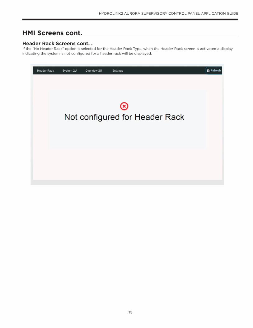
HMI Screens cont.
Header Rack Screens cont. .If the “No Header Rack” option is selected for the Header Rack Type, when the Header Rack screen is activated a display
indicating the system is not configured for a header rack will be displayed.

16
HYDROLINK2 AURORA SUPERVISORY CONTROL PANEL APPLICATION GUIDE
HMI Screens cont.
Overview Screen Displays chiller status, operation, compressor lockout status, heating and cooling set points, and compressor contactor
status. This screen gives an overview of each chiller.
Setpoint – (Heating / Cooling) the selected setpoint the unit is trying to maintain.
Control Temp – The current temperature of the control sensor.
Status: Displays the current overall fault status of chiller. “Normal” for normal operation or “Lockout” indicating the unit has
locked out due to a fault.
Operation: Displays the current operating condition of unit such as “Standby” or “Single Compressor Cooling.”
Mode: Displays the current operating mode selected of the chiller, and is adjustable from the Manual Operation screen on
Settings screen.
Circuit A & B: Displays the On/Off status, and the current lockout status of each compressor detected by Aurora Boards.

17
HYDROLINK2 AURORA SUPERVISORY CONTROL PANEL APPLICATION GUIDE
HMI Screens cont.
Settings Screen All temperature, network, or capacity settings for the system or HydroLink controller can be accessed or changed thru the
“Settings” screen. The method of temperature control, mode of operation, and manual operation all take place in this
screen.
18
HYDROLINK2 AURORA SUPERVISORY CONTROL PANEL APPLICATION GUIDE
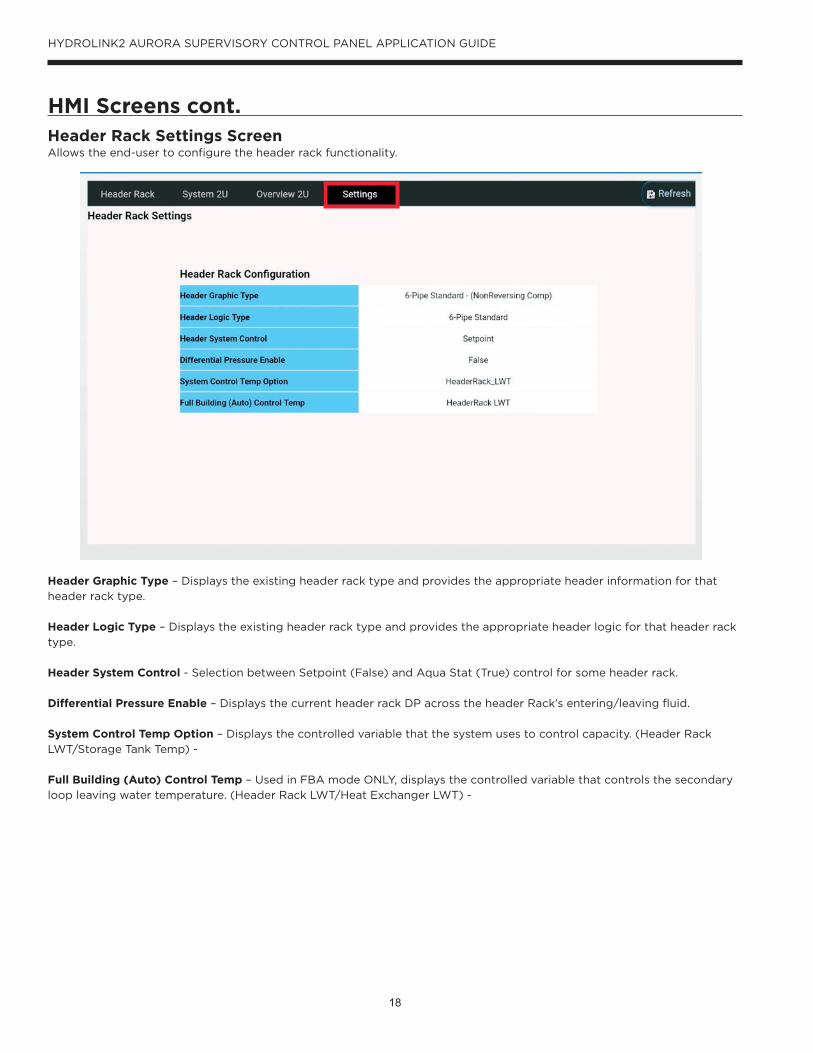
HMI Screens cont.Header Rack Settings ScreenAllows the end-user to configure the header rack functionality.
Header Graphic Type – Displays the existing header rack type and provides the appropriate header information for that
header rack type.
Header Logic Type – Displays the existing header rack type and provides the appropriate header logic for that header rack
type.
Header System Control - Selection between Setpoint (False) and Aqua Stat (True) control for some header rack.
Differential Pressure Enable – Displays the current header rack DP across the header Rack’s entering/leaving fluid.
System Control Temp Option – Displays the controlled variable that the system uses to control capacity. (Header Rack
LWT/Storage Tank Temp) -
Full Building (Auto) Control Temp – Used in FBA mode ONLY, displays the controlled variable that controls the secondary
loop leaving water temperature. (Header Rack LWT/Heat Exchanger LWT) -
19
HYDROLINK2 AURORA SUPERVISORY CONTROL PANEL APPLICATION GUIDE
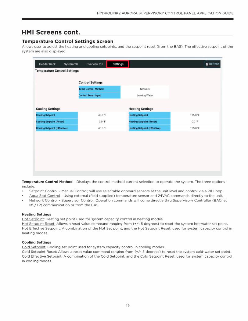
HMI Screens cont.Temperature Control Settings Screen Allows user to adjust the heating and cooling setpoints, and the setpoint reset (from the BAS). The effective setpoint of the
system are also displayed.
Temperature Control Method – Displays the control method current selection to operate the system. The three options
include:
• Setpoint Control – Manual Control; will use selectable onboard sensors at the unit level and control via a PID loop.
• Aqua Stat Control - Using external (field supplied) temperature sensor and 24VAC commands directly to the unit.
• Network Control – Supervisor Control; Operation commands will come directly thru Supervisory Controller (BACnet
MS/TP) communication or from the BAS.
Heating Settings Hot Setpoint: Heating set point used for system capacity control in heating modes.
Hot Setpoint Reset: Allows a reset value command ranging from {+/- 5 degrees} to reset the system hot-water set point.
Hot Effective Setpoint: A combination of the Hot Set point, and the Hot Setpoint Reset, used for system capacity control in
heating modes.
Cooling Settings
Cold Setpoint: Cooling set point used for system capacity control in cooling modes.
Cold Setpoint Reset: Allows a reset value command ranging from {+/- 5 degrees} to reset the system cold-water set point.
Cold Effective Setpoint: A combination of the Cold Setpoint, and the Cold Setpoint Reset, used for system capacity control
in cooling modes.
20
HYDROLINK2 AURORA SUPERVISORY CONTROL PANEL APPLICATION GUIDE
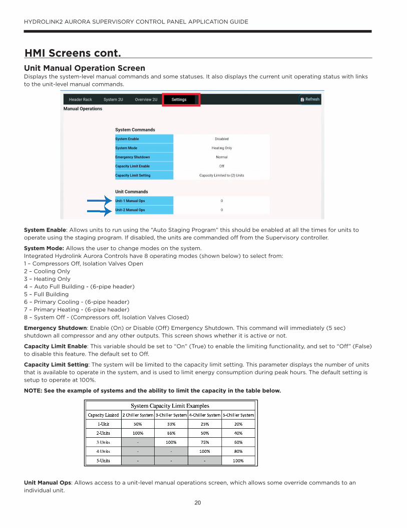
HMI Screens cont.Unit Manual Operation ScreenDisplays the system-level manual commands and some statuses. It also displays the current unit operating status with links
to the unit-level manual commands.
System Enable: Allows units to run using the “Auto Staging Program” this should be enabled at all the times for units to
operate using the staging program. If disabled, the units are commanded off from the Supervisory controller.
System Mode: Allows the user to change modes on the system.
Integrated Hydrolink Aurora Controls have 8 operating modes (shown below) to select from:
1 – Compressors Off, Isolation Valves Open
2 – Cooling Only
3 – Heating Only
4 – Auto Full Building - (6-pipe header)
5 – Full Building
6 – Primary Cooling - (6-pipe header)
7 – Primary Heating - (6-pipe header)
8 – System Off - (Compressors off, Isolation Valves Closed)
Emergency Shutdown: Enable (On) or Disable (Off) Emergency Shutdown. This command will immediately (5 sec)
shutdown all compressor and any other outputs. This screen shows whether it is active or not.
Capacity Limit Enable: This variable should be set to “On” (True) to enable the limiting functionality, and set to “Off” (False)
to disable this feature. The default set to Off.
Capacity Limit Setting: The system will be limited to the capacity limit setting. This parameter displays the number of units
that is available to operate in the system, and is used to limit energy consumption during peak hours. The default setting is
setup to operate at 100%.
NOTE: See the example of systems and the ability to limit the capacity in the table below.
Unit Manual Ops: Allows access to a unit-level manual operations screen, which allows some override commands to an
individual unit.

21
HYDROLINK2 AURORA SUPERVISORY CONTROL PANEL APPLICATION GUIDE
HMI Screens cont.
Unit Manual Operation Screen cont.Displays the unit-level manual commands and some active statuses. Allows the user to override some commands for
individual unit control.
Unit Manual Control Option
Emergency Shutdown: Will immediately (5 sec) shutdown all compressors and any other outputs. This screen shows
whether it is in shutdown or a normal state.
Reset Alarms:
• Reset - Allows program to reset the alarms.
• Normal - Allows program to operate as normal with no alarms.
Enable Override: If set to overridden, user will take unit out of the “Auto Staging Program” rotation and enable/disable unit
manually.
Mode Override: Must be set to “Auto” for HSC to stage. If “Not set to AUTO” user will take unit out of the “Auto Staging
Program” rotation and can pick a different mode for that unit.
Unit Control Program Option
Network Control: • Network - Indicates that the system is under Supervisory (HSC) control.
• Normal - Indicates the unit will operate as a stand-alone unit.
Temperature Control Method – Displays the control method current selection to operate the system. The three options
include,
• Setpoint Control – Manual Control; will use selectable onboard sensors at the unit level and control via a PID loop.
• Aqua stat Control - Using external (field supplied) temperature sensor and 24VAC commands directly to the unit.
• Network Control – Supervisor Control; Operation commands will come directly thru Supervisory Controller (BACnet
Mstp) communication.
Unit Active StatusThese values are indicating the unit’s current operating status.
NOTE: When the “Mode Override and/or Enable Override” feature is activated, the unit is taken out of the “Auto Staging
Program” sequence and will only operate manually via the Local- HMI at the chiller.

22
HYDROLINK2 AURORA SUPERVISORY CONTROL PANEL APPLICATION GUIDE
HMI Screens cont.
Capacity SettingsDisplays the staging values and parameters for increasing/decreasing capacity control for the system.
Unit Stage On Settings
Capacity Setpoint: (Adjustable) Refers to unit capacity setpoint.
This value is 1/3 part of the “stage on” criteria.
When the average capacity setpoint (Enabled Units) is greater than this value, the “stage on timer” will start.
Hot Delta: (Adjustable) Hot water stage on differential.
This value is 2/3 part of the “stage on” criteria (Applies when in Heating modes).
When the hot header leaving water temperature is less than the hot water set point, by the difference of this value, then the
“stage on timer” will start.
Cold Delta: (Adjustable) Chilled water stage on differential.
This value is 2/3 part of the “stage on” criteria (Applies when in Cooling modes).
When the cold header leaving water temperature is greater than the cold-water set point, by the difference of this value,
then the “stage on timer” will start.
Timer Setpoint: (Adjustable) This value is 3/3 part of the “stage on” criteria.
This timer will start when the enabled units, meet the criteria to stage on is met. When timer expires, and the stage on
criteria is satisfied, the next unit will be enabled with the least amount of runtime by the HSC.
Time Remaining: (Non-Adjustable) This value is 3/3 part of the “stage on” criteria.
The remaining time left of the “stage on timer” to enable the unit with the least amount of runtime..
23
HYDROLINK2 AURORA SUPERVISORY CONTROL PANEL APPLICATION GUIDE
Capacity Settings cont..
Unit Stage Off Settings
Capacity Setpoint: (Non-Adjustable) Refers to unit capacity setpoint.
This value is (1/3) part of the “stage off” criteria.
When the average capacity setpoint (Enabled Units) is less than this value the “stage off timer” will start.
Cold Delta: (Adjustable) Chilled water stage off differential.
This value is (2/3) part of the “stage off” criteria (Applies when in Cooling modes).
When the cold header leaving water temperature is less than the cold-water set point, by the difference of this value, then
the “stage off timer” will start.
Hot Delta: (Adjustable) Hot water stage off differential.
This value is (2/3) part of the “stage off” criteria (Applies when in Heating modes).
When the hot header leaving water temperature is greater than the hot water set point, by the difference of this value, then
the “stage off timer” will start.
Timer Setpoint: (Adjustable) This value is (3/3) part of the stage OFF criteria.
This timer will start when the enabled units, meet the criteria to “stage off” is met. When the timer expires, the unit with the
most amount of runtime will be disabled by the HSC.
Time Remaining: (Non-Adjustable) This value is (3/3) part of the “stage off” criteria.
The remaining time left of the “stage off timer” to disable the unit with the most amount of runtime.
Runtime: A calculated value that indicates the amount of time the compressors are operating.
Capacity SP: This value changes (from 0-100%) depending on the demand of the unit.
Circuit A/B: Compressor Off/On status Alarms Settings Displays alarm status and provides the ability to reset and change thresholds to adjust system alarms.
HMI Screens cont.
24
HYDROLINK2 AURORA SUPERVISORY CONTROL PANEL APPLICATION GUIDE
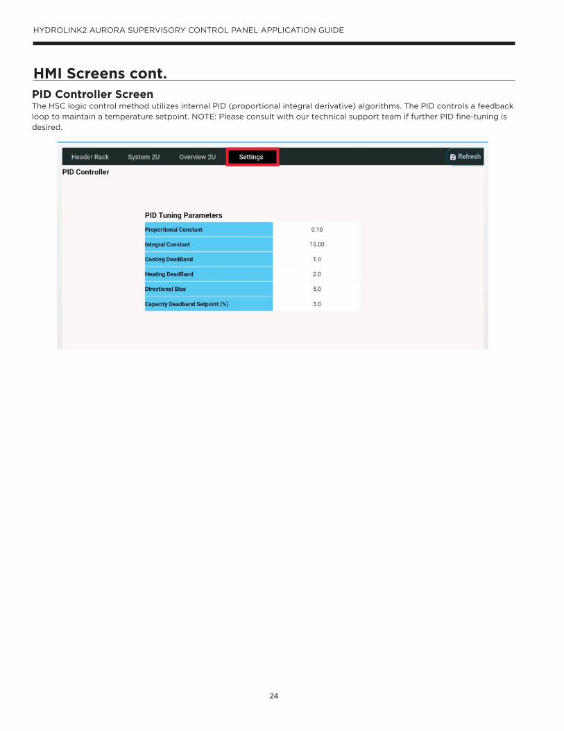
HMI Screens cont.PID Controller ScreenThe HSC logic control method utilizes internal PID (proportional integral derivative) algorithms. The PID controls a feedback
loop to maintain a temperature setpoint. NOTE: Please consult with our technical support team if further PID fine-tuning is
desired.
25
HYDROLINK2 AURORA SUPERVISORY CONTROL PANEL APPLICATION GUIDE
HMI Screens cont.
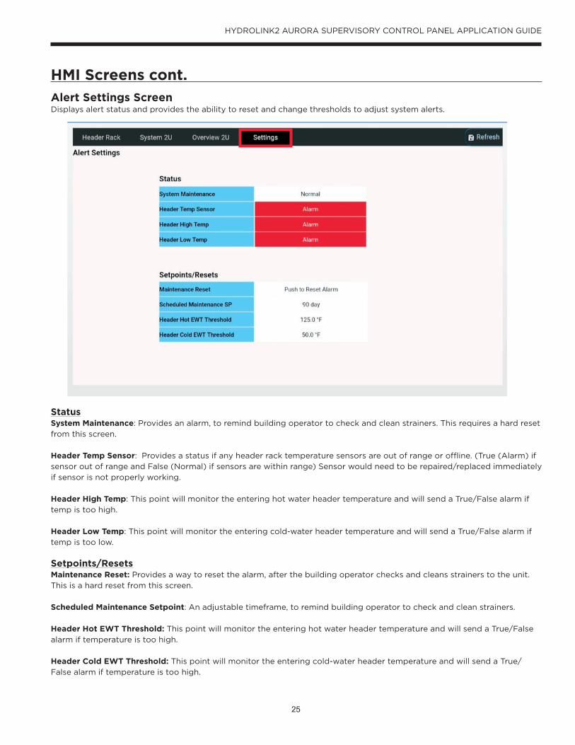
Alert Settings ScreenDisplays alert status and provides the ability to reset and change thresholds to adjust system alerts.
StatusSystem Maintenance: Provides an alarm, to remind building operator to check and clean strainers. This requires a hard reset
from this screen.
Header Temp Sensor: Provides a status if any header rack temperature sensors are out of range or offline. (True (Alarm) if
sensor out of range and False (Normal) if sensors are within range) Sensor would need to be repaired/replaced immediately
if sensor is not properly working.
Header High Temp: This point will monitor the entering hot water header temperature and will send a True/False alarm if
temp is too high.
Header Low Temp: This point will monitor the entering cold-water header temperature and will send a True/False alarm if
temp is too low.
Setpoints/ResetsMaintenance Reset: Provides a way to reset the alarm, after the building operator checks and cleans strainers to the unit.
This is a hard reset from this screen.
Scheduled Maintenance Setpoint: An adjustable timeframe, to remind building operator to check and clean strainers.
Header Hot EWT Threshold: This point will monitor the entering hot water header temperature and will send a True/False
alarm if temperature is too high.
Header Cold EWT Threshold: This point will monitor the entering cold-water header temperature and will send a True/
False alarm if temperature is too high.
26
HYDROLINK2 AURORA SUPERVISORY CONTROL PANEL APPLICATION GUIDE
HMI Screens cont.
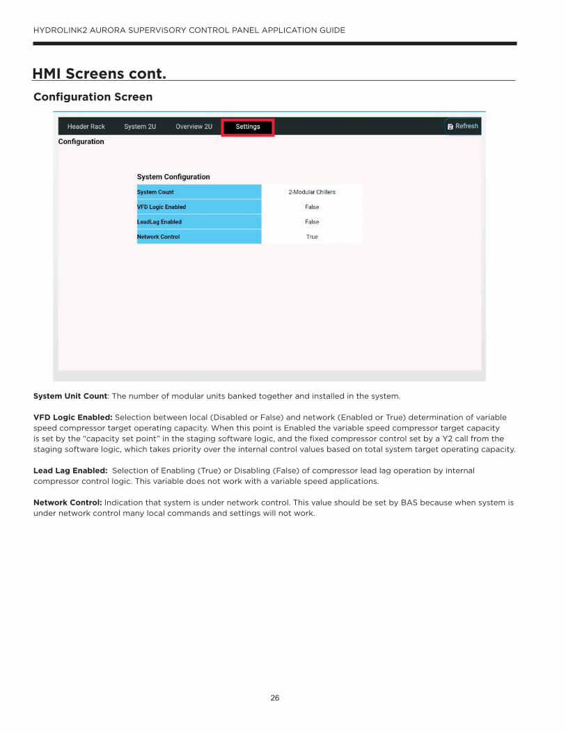
Configuration Screen
System Unit Count: The number of modular units banked together and installed in the system.
VFD Logic Enabled: Selection between local (Disabled or False) and network (Enabled or True) determination of variable
speed compressor target operating capacity. When this point is Enabled the variable speed compressor target capacity
is set by the “capacity set point” in the staging software logic, and the fixed compressor control set by a Y2 call from the
staging software logic, which takes priority over the internal control values based on total system target operating capacity.
Lead Lag Enabled: Selection of Enabling (True) or Disabling (False) of compressor lead lag operation by internal
compressor control logic. This variable does not work with a variable speed applications.
Network Control: Indication that system is under network control. This value should be set by BAS because when system is
under network control many local commands and settings will not work.

27
HYDROLINK2 AURORA SUPERVISORY CONTROL PANEL APPLICATION GUIDE
HMI Screens cont.
BACnet/MSTP Configuration Screen Building Automation – RS485-2 {Com 2}
This section is for the BAS to configure the HSC to tie into the Automation System via Mstp.
To Local Units – RS485-1 {Com 1}This section is for the Startup Tech to configure the HSC to communicate to the Module Units.
Building Automation – IP-en0 {Primary}This section is for the BAS to configure the HSC to tie into the Automation System via IP.
Local Units Enabled – RS485-1 {Com 1}This section is for the Startup Tech to configure the HSC to communicate to the Module Units.
Network Number: The network number should be defaulted at 8100 for the local units. It can be configured to integrate per
building automation system contractor.
Object ID: The object ID is a read only status on the HMI. However, can be adjusted by a factory technician.
Baud Rate: Selectable from several speeds.
Address: Unique MAC Address
Max Master: Highest network number available.
28
HYDROLINK2 AURORA SUPERVISORY CONTROL PANEL APPLICATION GUIDE
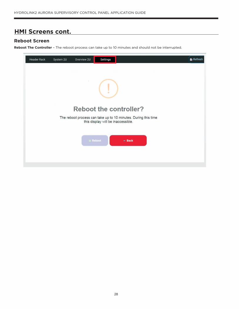
HMI Screens cont.
Reboot ScreenReboot The Controller – The reboot process can take up to 10 minutes and should not be interrupted.

29
HYDROLINK2 AURORA SUPERVISORY CONTROL PANEL APPLICATION GUIDE
HMI Screens Layout
PID Controller
System Configuration
HydroLink2 Supervisory Control Panel HMI
Header Rack Settings
Temperature Control Settings
Manual Operations
Capacity Settings
Chiller Manual Commands
HydroLink Supervisory Control Panels “System Configuration” should be completed by a factory trained start-up tech to ensure proper operation.
BacNet/MSTP Configuration
Reboot Controller
System
Alert Settings
Configuration
HydroLink Controller
HydroLink2 Login Screen
System
Settings
Header Rack
Overview

30
HYDROLINK2 AURORA SUPERVISORY CONTROL PANEL APPLICATION GUIDE
Change HSC Network IP Address1. To change the Ip address on the HSC via the HMI, Swipe upward from the bottom of the tablet on any screen.
2. Press the (black colored, white trimmed, circle shaped) “Home” button to return to the home screen.
3. Press the (6-black dots inside a white circle shape) “App” button
4. Open up Google Chrome web browser and enter the HSC Ip address in the web address bar.
5. Enter the proper credentials listed below:
UN: user
PW: Networkip
6. Press the “Login” button to login to the HSC Tcp Ip Platform Service Plugin.
7. Proceed to change the “en0” port, which is the primary port.

31
HYDROLINK2 AURORA SUPERVISORY CONTROL PANEL APPLICATION GUIDE
Change HSC Network IP Address cont.
8. Once the new Ip address has been entered, scroll to the bottom of the screen and click “SAVE.”
9. Then, the system will need to reboot to make the changes. It will prompt you to continue, Click “OK”
10. The system will take up to 10 minutes to reboot and start up. Be patient. Then return to the “Home” screen on the HMI
and launch the HydroLink app.
32
HYDROLINK2 AURORA SUPERVISORY CONTROL PANEL APPLICATION GUIDE
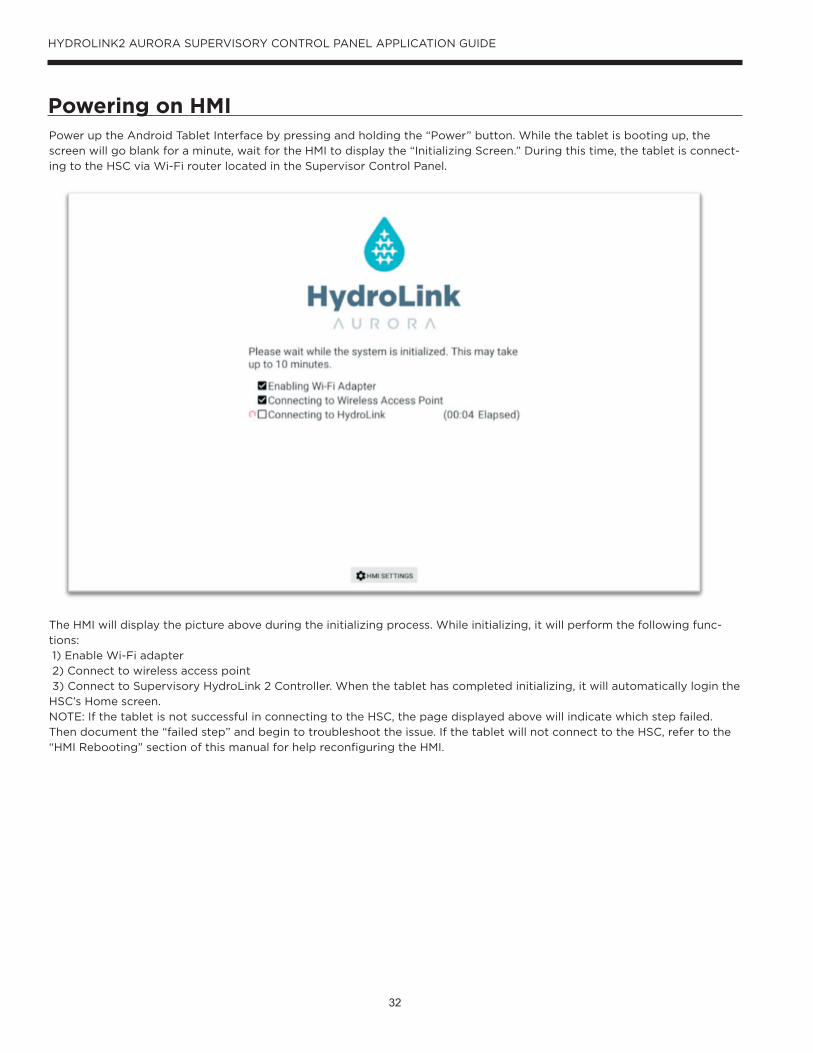
Powering on HMIPower up the Android Tablet Interface by pressing and holding the “Power” button. While the tablet is booting up, the
screen will go blank for a minute, wait for the HMI to display the “Initializing Screen.” During this time, the tablet is connect-
ing to the HSC via Wi-Fi router located in the Supervisor Control Panel.
The HMI will display the picture above during the initializing process. While initializing, it will perform the following func-
tions:
1) Enable Wi-Fi adapter
2) Connect to wireless access point
3) Connect to Supervisory HydroLink 2 Controller. When the tablet has completed initializing, it will automatically login the
HSC’s Home screen.
NOTE: If the tablet is not successful in connecting to the HSC, the page displayed above will indicate which step failed.
Then document the “failed step” and begin to troubleshoot the issue. If the tablet will not connect to the HSC, refer to the
“HMI Rebooting” section of this manual for help reconfiguring the HMI.

33
HYDROLINK2 AURORA SUPERVISORY CONTROL PANEL APPLICATION GUIDE
Login Screen (Pre Factory Tech Startup) First Time ConnectingNOTE: When powering up the HMI for the first time, the “System Login” screen will look like the picture above. The entire navigation bar (at the top of screen) are disabled. At this point, contact the manufacture to schedule a required Factory Tech Startup for your system. During startup, the Technician will need to complete the “Configuration Setup” and safely start the chillers. After the configuration setup is complete, the “System Login” screen will display an Enabled “System” button that will allow the user to view the system operating status.

34
HYDROLINK2 AURORA SUPERVISORY CONTROL PANEL APPLICATION GUIDE
Application Example: Four Pipe Standard Header Rack
with Fixed Capacity Scroll Dedicated Chiller
35
HYDROLINK2 AURORA SUPERVISORY CONTROL PANEL APPLICATION GUIDE
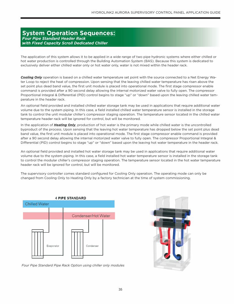
The application of this system allows it to be applied in a wide range of two pipe hydronic systems where either chilled or hot water production is controlled through the Building Automation System (BAS). Because this system is dedicated to exclusively deliver either chilled water only or hot water only, water is not mixed within the header rack.
Cooling Only operation is based on a chilled water temperature set point with the source connected to a Net Energy Wa-
ter Loop to reject the heat of compression. Upon sensing that the leaving chilled water temperature has risen above the
set point plus dead band value, the first unit module is placed into operational mode. The first stage compressor enable
command is provided after a 90 second delay allowing the internal motorized water valve to fully open. The compressor
Proportional Integral & Differential (PID) control begins to stage “up” or “down” based upon the leaving chilled water tem-
perature in the header rack.
An optional field provided and installed chilled water storage tank may be used in applications that require additional water
volume due to the system piping. In this case, a field installed chilled water temperature sensor is installed in the storage
tank to control the unit modular chiller’s compressor staging operation. The temperature sensor located in the chilled water
temperature header rack will be ignored for control, but will be monitored.
In the application of Heating Only, production of hot water is the primary mode while chilled water is the uncontrolled
byproduct of the process. Upon sensing that the leaving hot water temperature has dropped below the set point plus dead
band value, the first unit module is placed into operational mode. The first stage compressor enable command is provided
after a 90 second delay allowing the internal motorized water valve to fully open. The compressor Proportional Integral &
Differential (PID) control begins to stage “up” or “down” based upon the leaving hot water temperature in the header rack.
An optional field provided and installed hot water storage tank may be used in applications that require additional water
volume due to the system piping. In this case, a field installed hot water temperature sensor is installed in the storage tank
to control the modular chiller’s compressor staging operation. The temperature sensor located in the hot water temperature
header rack will be ignored for control, but will be monitored.
The supervisory controller comes standard configured for Cooling Only operation. The operating mode can only be
changed from Cooling Only to Heating Only by a factory technician at the time of system commissioning.
Four Pipe Standard Pipe Rack Option using chiller only modules
System Operation Sequences: Four Pipe Standard Header Rack with Fixed Capacity Scroll Dedicated Chiller

36
HYDROLINK2 AURORA SUPERVISORY CONTROL PANEL APPLICATION GUIDE
Controller ConfigurationThe communications links (RS-485 and Ethernet) may be field configured for setting an address, device instance and baud
rate where applicable. The staging can be scaled in the field to support 2 to 10 stages of compressor capacity. The run time
equalization feature may be enabled or disabled in the field.
Operator FunctionsThe local display will support multiple access level users to allow read-only, Building User/Owner, and factory admin-level
access. The Building User/Owner will be able to adjust the operating temperature set point, enable/disable the system,
reset lockout alarms, and view detailed unit summaries.
Water ControlOne of the primary functions of the supervisory controller is to manage the water flow through the modular chiller plant
to maintain efficient system water circulation. When the system is enabled, the 2-way water isolation valve on a single
specified unit module will be commanded open so that the water can circulate. When the staging algorithm starts the first
unit module in the sequence, then the isolation valve that was opened for circulation will be allowed to close again and will
remain closed until the associated unit is commanded on or until all other isolation valves have closed—provided that the
System Enable command is still ON.
Optional Bypass Control: The optional bypass control is available to prevent dead heading of the system water circulating
pumps in a variable volume system when all of the unit modules water control valves are closed and is recommended for
use with all piping header racks. When the system is enabled, the 2-way water bypass valve will be commanded open so
that the water can circulate through the bypass. When the staging algorithm starts the first unit module in the sequence,
then the bypass valve that was opened for circulation will be allowed to close again and will remain closed until all other
unit module isolation valves have closed.
LABEL*LABEL **(PART NUMBER)
TEMPERATURE SENSOR
TEMPERATURE SENSOR
UNIT SIDE
UNIT SIDE
PRESSURE TRANSDUCER **
PRESSURE TRANSDUCER ***
OUTLET
INLET
Functions: Four Pipe Standard Header Rack with Fixed Capacity Scroll Dedicated Chiller
37
HYDROLINK2 AURORA SUPERVISORY CONTROL PANEL APPLICATION GUIDE
Temperature Control
Another primary function of the supervisory controller is to provide control of the water temperature by staging on or off
the compressors in the array of chillers based upon the commanded temperature set point communicated over the BAS.
The compressor staging PID algorithm compares the chiller plant leaving water temperature*, trending over an adjustable
time period, to the commanded water temperature set point in order to determine system demand. The sequencing logic
will respond to changes in the system demand by initiating or terminating compressor “enable” or “disable” commands to
the unit module(s). If the demand is increasing and crosses the threshold for starting another compressor, the sequenc-
ing logic will select and enable the unit module with the least amount of accumulated compressor run time and then issue
an “enable” command to the compressor with the lowest run time. In the event that a unit module is already operating a
lead compressor, the controller will issue an “enable” command to the lag compressor of that unit module. As the system
demand decreases and crosses the threshold for halting compressor operation, the sequencing logic will issue a “disable”
command to the compressor with the highest run time.
* Optional entering water temperature control available as an engineering special; contact factory.
Chilled Water Reset Function: a customer supplied external signal commanded over the BAS that shifts the chilled water
temperature set point higher from 0 - 10°F to maximize plant efficiency.
Hot Water Reset Function: a customer supplied external signal commanded over the BAS that shifts the hot water tem-
perature set point lower from 0 - 10°F to maximize plant efficiency.
Load Limit Function: a customer supplied external signal commanded over the BAS (0-100%) that limits the number of
compressors that are available to be staged in order to limit electrical consumption of the central chiller plant.
Run Time Equalization
A run time equalization feature can be enabled or disabled. Run time is per unit module, and is the combined run time of
both compressors in the unit. If the run time equalization feature is enabled, when an additional unit module is needed for
increased capacity, the next compressor call will be issued to the unit with the lowest run time of the inactive unit modules.
In the event of a lock-out fault on a compressor, the staging algorithm will bypass that unit module and use the one with
the next lowest run time. Units with faulted compressors will be placed at the back of the line in the sequencing order. This
will still allow single compressor operation if one of the two compressors is disabled.
System Notifications and Failure Alarms
The supervisory controller monitors the operation of each unit module within the chiller plant, but also monitors a number
of system functions in order to provide notification and or alarms over the BAS.
Scheduled Maintenance Notification: General system notification based upon accumulated run hours.
Sensor Failure Alarm: Controlling water temperature sensor failure shuts down system and initiates alarm. All other sensors
will only initiate an alarm.
High Condenser Temperature Alarm: Adjustable alarm point based upon entering condenser/net energy water loop tem-
perature at chiller.
Low Evaporator Temperature Alarm: Adjustable alarm point based upon leaving chilled water temperature at chiller.
Remote Stop Alarm: Alarm that the chiller plant operation has been halted by a BAS command.
Emergency Stop Alarm: Provides notification that the operation of a single unit module has been halted as a result of an
operator depressing the unit’s emergency shut down push button. Can be configured, by a factory technician at the time of
system commissioning, to halt entire system operation and initiate alarm in the event that a single unit module’s emergency
shut down push button has been depressed.
Refrigerant Monitor Alarm (Field Provided and Wired): Upon receiving an input from a refrigerant monitor, the entire sys-
tem operation is halted and initiates an additional system alarm.
Functions: Four Pipe Standard Header Rack with Fixed Capacity Scroll Dedicated Chiller

38
HYDROLINK2 AURORA SUPERVISORY CONTROL PANEL APPLICATION GUIDE
Control Inputs and Outputs: Four Pipe Standard Header Rack with Fixed Capacity Scroll Dedicated Chiller
System Network InputsCooling Only Mode
• “Hand/Off/Auto” Selection
• Plant “Enable”/”Disable” Command
• Plant Mode Command (“Cooling”)
• Chilled Water Temperature Set Point
• Differential Water Pressure Set Points (optional: chilled water/source/net energy water)
• Chilled Water Temperature Reset (optional)
• Load Limiting Status (optional)
• Remote Plant Shutdown (optional)
Heating Only Mode
• “Hand/Off/Auto” Selection
• Plant “Enable”/”Disable” Command
• Plant Mode Command (“Heating”)
• Hot Water Temperature Set Point
• Differential Water Pressure Set Points (optional: chilled water/source/net energy water)
• Hot Water Temperature Reset (optional)
• Load Limiting Status (optional)
• Remote Plant Shutdown (optional)
System Control OutputsThe Niagara Direct Input Output Module features digital and analog outputs to provide control of relays and speed refer-
ence outputs on VFDs or positioning outputs on modulating actuators.
Cooling Only Mode
• Alarm Relay/Annunciator (optional)
• Remote Chilled Water Pump Speed Reference
• Chilled Water Bypass Valve*
• Remote Source/Net Energy Water Pump Speed Reference
• Source/Net Energy Water Bypass Valve*
*Field installed in bypass header assembly if system configured for water bypass
Heating Only Mode
• Alarm Relay/Annunciator (optional)
• Remote Hot Water Pump Speed Reference
• Hot Water Bypass Valve*
• Remote Source/Net Energy Water Pump Speed Reference
• Source/Net Energy Water Bypass Valve*
*Field installed in bypass header assembly if system configured for water bypass

39
HYDROLINK2 AURORA SUPERVISORY CONTROL PANEL APPLICATION GUIDE
Control Inputs and Outputs: Four Pipe Standard Header Rack with Fixed Capacity Scroll Dedicated Chiller
System Network Outputs Cooling Only Mode
• Entering Chilled Water Temperature
• Leaving Chilled Water Temperature
• Estimated Chilled Water Flow Rate
• Chilled Water Bypass Valve Position*
• Estimated Chilled Water Plant Load
• Entering Source/Net Energy Water Loop Temperature
• Leaving Source/Net Energy Water Loop Temperature
• Estimated Source/Net Energy Water Flow Rate
• Source/Net Energy Water Bypass Valve Position*
• Estimated Source/Net Energy Water Plant Load
• Active Module(s)
• Active Compressor(s)
• Active System and Unit Module Alarm(s)
*Field installed in bypass header assembly if system configured for water bypass
Heating Only Mode
• Entering Hot Water Temperature
• Leaving Hot Water Temperature
• Estimated Hot Water Flow Rate
• Hot Water Bypass Valve Position*
• Estimated Hot Water Plant Load
• Entering Source/Net Energy Water Loop Temperature
• Leaving Source/Net Energy Water Loop Temperature
• Estimated Source/Net Energy Water Flow Rate
• Source/Net Energy Water Bypass Valve Position*
• Estimated Source/Net Energy Water Plant Load
• Active Module(s)
• Active Compressor(s)
• Active System and Unit Module Alarm(s)
*Field installed in bypass header assembly if system configured for water bypass

40
HYDROLINK2 AURORA SUPERVISORY CONTROL PANEL APPLICATION GUIDE
Application Example: Four Pipe Reversing Header Rack with Fixed Capacity Scroll
Dedicated Chiller

41
HYDROLINK2 AURORA SUPERVISORY CONTROL PANEL APPLICATION GUIDE
The application of this system allows it to be applied in a wide range of two pipe hydronic systems where chilled or hot
water production is controlled through the Building Automation System (BAS). This system utilizes the three way water
control valves within the header rack to reverse the water flow through the evaporator and condenser which allows water
to be mixed within the system.
Cooling operation is based on a chilled water temperature set point with the source connected to a Net Energy Water Loop
to reject the heat of compression. Upon sensing that the leaving chilled water temperature has risen above the set point
plus dead band value, the first unit module is placed into operational mode. The first stage compressor enable command
is provided after a 90 second delay allowing the internal motorized water valve to fully open. The compressor Proportional
Integral & Differential (PID) control begins to stage “up” or “down” based upon the leaving chilled water temperature in the
header rack.
An optional field provided and installed chilled water storage tank may be used in applications that require additional water
volume due to the system piping. In this case, a field installed chilled water temperature sensor is installed in the storage
tank to control the modular chiller’s compressor staging operation. The temperature sensor located in the chilled water
temperature header rack will be ignored for control, but will be monitored.
During Heating operation, the three-way water valves in the header rack are energized to reverse the flow of water through
the unit module in order to produce hot water. Upon sensing that the leaving hot water temperature has dropped below
the set point plus dead band value, the first unit module is placed into operational mode. The first stage compressor enable
command is provided after a 90 second delay allowing the internal motorized water valve to fully open. The compressor
Proportional Integral & Differential (PID) control begins to stage “up” or “down” based upon the leaving hot water tempera-
ture in the header rack.
An optional field provided and installed hot water storage tank may be used in applications that require additional water
volume due to the system piping. In this case, a field installed hot water temperature sensor is installed in the storage tank
to control the modular chiller’s compressor staging operation. The temperature sensor located in the hot water temperature
header rack will be ignored for control, but will be monitored.
Four Pipe Reversing Pipe Rack Option using chiller only modules
System Operation Sequences: Four Pipe Reversing Header Rack with Fixed Capacity Scroll Dedicated Chiller

42
HYDROLINK2 AURORA SUPERVISORY CONTROL PANEL APPLICATION GUIDE
Controller Configuration
The communications links (RS-485 and Ethernet) may be field configured for setting an address, device instance and baud
rate where applicable. The staging can be scaled in the field to support 2 to 10 stages of compressor capacity. The run time
equalization feature may be enabled or disabled in the field.
Operator Functions
The local display will support multiple access level users to allow read-only, Building User/Owner, and factory admin-level
access. The Building User/Owner will be able to adjust the operating temperature set point, “enable/disable the system,
reset lockout alarms, and view detailed unit summaries.
Water Control
One of the primary functions of the supervisory controller is to manage the water flow through the modular chiller plant to
maintain efficient system water circulation. When the system is enabled, the 2-way water isolation valve on a single speci-
fied unit module will be commanded open so that the water can circulate. When the staging algorithm starts the first unit
module in the sequence, then the isolation valve that was opened for circulation will be allowed to close again and will
remain closed until the associated unit is commanded on or until all other isolation valves have closed—provided that the
System Enable command is still ON.
Optional Bypass Control: The optional bypass control is available to prevent dead heading of the system water circulating
pumps in a variable volume system when all of the unit modules water control valves are closed and is recommended for
use with all piping header racks. When the system is enabled, the 2-way water bypass valve will be commanded open so
that the water can circulate through the bypass. When the staging algorithm starts the first unit module in the sequence,
then the bypass valve that was opened for circulation will be allowed to close again and will remain closed until all other
unit module isolation valves have closed
LABEL*LABEL **(PART NUMBER)
TEMPERATURE SENSOR
TEMPERATURE SENSOR
UNIT SIDE
UNIT SIDE
PRESSURE TRANSDUCER **
PRESSURE TRANSDUCER ***
OUTLET
INLET
Functions: Four Pipe Reversing Header Rack with Fixed Capacity Scroll Dedicated Chiller

43
HYDROLINK2 AURORA SUPERVISORY CONTROL PANEL APPLICATION GUIDE
Temperature Control
Another primary function of the supervisory controller is to provide control of the water temperature by staging on or off
the compressors in the array of chillers based upon the commanded temperature set point communicated over the BAS.
The compressor staging PID algorithm compares the chiller plant leaving water temperature*, trending over an adjustable
time period, to the commanded water temperature set point in order to determine system demand. The sequencing logic
will respond to changes in the system demand by initiating or terminating compressor “enable” or “disable” commands to
the unit module(s). If the demand is increasing and crosses the threshold for starting another compressor, the sequenc-
ing logic will select and enable the unit module with the least amount of accumulated compressor run time and then issue
an “enable” command to the compressor with the lowest run time. In the event that a unit module is already operating a
lead compressor, the controller will issue an “enable” command to the lag compressor of that unit module. As the system
demand decreases and crosses the threshold for halting compressor operation, the sequencing logic will issue a “disable”
command to the compressor with the highest run time.
* Optional entering water temperature control available as an engineering special; contact factory.
Chilled Water Reset Function: a customer supplied external signal commanded over the BAS that shifts the chilled water
temperature set point higher from 0 - 10°F to maximize plant efficiency.
Hot Water Reset Function: a customer supplied external signal commanded over the BAS that shifts the hot water tem-
perature set point lower from 0 - 10°F to maximize plant efficiency.
Load Limit Function: a customer supplied external signal commanded over the BAS (0-100%) that limits the number of
compressors that are available to be staged in order to limit electrical consumption of the central chiller plant.
Run Time Equalization
A run time equalization feature can be enabled or disabled. Run time is per unit module, and is the combined run time of
both compressors in the unit. If the run time equalization feature is enabled, when an additional unit module is needed for
increased capacity, the next compressor call will be issued to the unit with the lowest run time of the inactive unit modules.
In the event of a lock-out fault on a compressor, the staging algorithm will bypass that unit module and use the one with
the next lowest run time. Units with faulted compressors will be placed at the back of the line in the sequencing order. This
will still allow single compressor operation if one of the two compressors is disabled.
System Notifications and Failure Alarms
The supervisory controller monitors the operation of each unit module within the chiller plant, but also monitors a number
of system functions in order to provide notification and or alarms over the BAS.
Scheduled Maintenance Notification: General system notification based upon accumulated run hours.
Sensor Failure Alarm: Controlling water temperature sensor failure shuts down system and initiates alarm. All other sensors
will only initiate an alarm.
High Condenser Temperature Alarm: Adjustable alarm point based upon entering condenser/net energy water loop tem-
perature at chiller.
Low Evaporator Temperature Alarm: Adjustable alarm point based upon leaving chilled water temperature at chiller.
Remote Stop Alarm: Alarm that the chiller plant operation has been halted by a BAS command.
Emergency Stop Alarm: Provides notification that the operation of a single unit module has been halted as a result of an
operator depressing the unit’s emergency shut down push button. Can be configured, by a factory technician at the time of
system commissioning, to halt entire system operation and initiate alarm in the event that a single unit module’s emergency
shut down push button has been depressed.
Refrigerant Monitor Alarm (Field Provided and Wired): Upon receiving an input from a refrigerant monitor, the entire sys-
tem operation is halted and initiates an additional system alarm.
Functions: Four Pipe Reversing Header Rack with Fixed Capacity Scroll Dedicated Chiller

44
HYDROLINK2 AURORA SUPERVISORY CONTROL PANEL APPLICATION GUIDE
System Network InputsCooling Mode
• “Hand/Off/Auto” Selection
• Plant “Enable”/”Disable” Command
• Plant Mode Command (“Cooling”)
• Chilled Water Temperature Set Point
• Differential Water Pressure Set Points (optional: chilled water/source/net energy water)
• Chilled Water Temperature Reset (optional)
• Load Limiting Status (optional)
• Remote Plant Shutdown (optional)
Heating Mode
• “Hand/Off/Auto” Selection
• Plant “Enable”/”Disable” Command
• Plant Mode Command (“Heating”)
• Hot Water Temperature Set Point
• Differential Water Pressure Set Points (optional: chilled water/source/net energy water)
• Hot Water Temperature Reset (optional)
• Load Limiting Status (optional)
• Remote Plant Shutdown (optional)
System Control OutputsThe Niagara Direct Input Output Module features digital and analog outputs to provide control of relays and speed refer-
ence outputs on VFDs or positioning outputs on modulating actuators.
Cooling Mode
• Alarm Relay/Annunciator (optional)
• Remote Chilled Water Pump Speed Reference
• Chilled Water Bypass Valve*
• Remote Source/Net Energy Water Pump Speed Reference
• Source/Net Energy Water Bypass Valve*
*Field installed in bypass header assembly if system configured for water bypass
Heating Mode
• Alarm Relay/Annunciator (optional)
• Remote Hot Water Pump Speed Reference
• Hot Water Bypass Valve*
• Remote Source/Net Energy Water Pump Speed Reference
• Source/Net Energy Water Bypass Valve*
*Field installed in bypass header assembly if system configured for water bypass
Control Inputs and Outputs: Four Pipe Reversing Header Rack with Fixed Capacity Scroll Dedicated Chiller
45
HYDROLINK2 AURORA SUPERVISORY CONTROL PANEL APPLICATION GUIDE
System Network Outputs Cooling Mode
• Entering Chilled Water Temperature
• Leaving Chilled Water Temperature
• Estimated Chilled Water Flow Rate
• Chilled Water Bypass Valve Position*
• Estimated Chilled Water Plant Load
• Entering Source/Net Energy Water Loop Temperature
• Leaving Source/Net Energy Water Loop Temperature
• Estimated Source/Net Energy Water Flow Rate
• Source/Net Energy Water Bypass Valve Position*
• Estimated Source/Net Energy Water Plant Load
• Active Module(s)
• Active Compressor(s)
• Active System and Unit Module Alarm(s)
*Field installed in bypass header assembly if system configured for water bypass
Heating Mode
• Entering Hot Water Temperature
• Leaving Hot Water Temperature
• Estimated Hot Water Flow Rate
• Hot Water Bypass Valve Position*
• Estimated Hot Water Plant Load
• Entering Source/Net Energy Water Loop Temperature
• Leaving Source/Net Energy Water Loop Temperature
• Estimated Source/Net Energy Water Flow Rate
• Source/Net Energy Water Bypass Valve Position*
• Estimated Source/Net Energy Water Plant Load
• Active Module(s)
• Active Compressor(s)
• Active System and Unit Module Alarm(s)
*Field installed in bypass header assembly if system configured for water bypass
Control Inputs and Outputs: Four Pipe Reversing Header Rack with Fixed Capacity Scroll Dedicated Chiller

46
HYDROLINK2 AURORA SUPERVISORY CONTROL PANEL APPLICATION GUIDE
Application Example: Four Pipe Standard Header Rack with Fixed Capacity Scroll
Reversible Chiller

47
HYDROLINK2 AURORA SUPERVISORY CONTROL PANEL APPLICATION GUIDE
The operation of this system allows it to be applied in a wide range of two pipe hydronic systems where the system change over between cooling and heating is controlled through the Building Automation System (BAS). Because this system uti-lizes refrigerant reversing valves within the reversible chiller, water is not mixed within the header rack.
Cooling operation based on a chilled water temperature set point with the source connected to a Net Energy Water Loop
to reject the heat of compression. Upon sensing that the leaving chilled water temperature has risen above the set point
plus dead band value, the first unit module is placed into operational mode. The first stage compressor enable command
is provided after a 90 second delay allowing the internal motorized water valve to fully open. The compressor Proportional
Integral & Differential (PID) control begins to stage “up” or “down” based upon the leaving chilled water temperature in the
header rack.
An optional field provided and installed chilled water storage tank may be used in applications that require additional water
volume due to the system piping. In this case, a field installed chilled water temperature sensor is installed in the storage
tank to control the modular chiller’s compressor staging. The temperature sensor located in the chilled water temperature
header rack will be ignored for control, but will be monitored.
During Heating operation, the refrigerant reversing valve is energized so that the flow of refrigerant changes within the
unit module in order to produce hot water. Upon sensing that the leaving hot water temperature has dropped below the
set point plus dead band value, the first unit module is placed into operational mode. The first stage compressor enable
command is provided after a 90 second delay allowing the internal motorized water valve to fully open. The compressor
Proportional Integral & Differential (PID) control begins to stage “up” or “down” based upon the leaving hot water tempera-
ture in the header rack.
An optional field provided and installed hot water storage tank may be used in applications that require additional water
volume due to the system piping. In this case, a field installed hot water temperature sensor is installed in the storage tank
to control the modular chiller’s compressor staging. The temperature sensor located in the hot water temperature header
rack will be ignored for control, but will be monitored.
Four Pipe Standard Pipe Rack Option using reversible chiller modules
System Operation Sequences: Four Pipe Standard Header Rack with Fixed Capacity Scroll Reversible Chiller

48
HYDROLINK2 AURORA SUPERVISORY CONTROL PANEL APPLICATION GUIDE
Controller Configuration
The communications links (RS-485 and Ethernet) may be field configured for setting an address, device instance and baud
rate where applicable. The staging can be scaled in the field to support 2 to 10 stages of compressor capacity. The run time
equalization feature may be enabled or disabled in the field.
Operator Functions
The local display will support multiple access level users to allow read-only, Building User/Owner, and factory admin-level
access. The Building User/Owner will be able to adjust the operating temperature set point, “enable/disable the system,
reset lockout alarms, and view detailed unit summaries.
Water Control
One of the primary functions of the supervisory controller is to manage the water flow through the modular chiller plant to
maintain efficient system water circulation. When the system is enabled, the 2-way water isolation valve on a single speci-
fied unit module will be commanded open so that the water can circulate. When the staging algorithm starts the first unit
module in the sequence, then the isolation valve that was opened for circulation will be allowed to close again and will
remain closed until the associated unit is commanded on or until all other isolation valves have closed—provided that the
System Enable command is still ON.
Optional Bypass Control: The optional bypass control is available to prevent dead heading of the system water circulating
pumps in a variable volume system when all of the unit modules water control valves are closed and is recommended for
use with all piping header racks. When the system is enabled, the 2-way water bypass valve will be commanded open so
that the water can circulate through the bypass. When the staging algorithm starts the first unit module in the sequence,
then the bypass valve that was opened for circulation will be allowed to close again and will remain closed until all other
unit module isolation valves have closed
LABEL*LABEL **(PART NUMBER)
TEMPERATURE SENSOR
TEMPERATURE SENSOR
UNIT SIDE
UNIT SIDE
PRESSURE TRANSDUCER **
PRESSURE TRANSDUCER ***
OUTLET
INLET
Functions: Four Pipe Standard Header Rack with Fixed Capacity Scroll Reversible Chiller

49
HYDROLINK2 AURORA SUPERVISORY CONTROL PANEL APPLICATION GUIDE
Temperature Control
Another primary function of the supervisory controller is to provide control of the water temperature by staging on or off
the compressors in the array of chillers based upon the commanded temperature set point communicated over the BAS.
The compressor staging PID algorithm compares the chiller plant leaving water temperature*, trending over an adjustable
time period, to the commanded water temperature set point in order to determine system demand. The sequencing logic
will respond to changes in the system demand by initiating or terminating compressor “enable” or “disable” commands to
the unit module(s). If the demand is increasing and crosses the threshold for starting another compressor, the sequenc-
ing logic will select and enable the unit module with the least amount of accumulated compressor run time and then issue
an “enable” command to the compressor with the lowest run time. In the event that a unit module is already operating a
lead compressor, the controller will issue an “enable” command to the lag compressor of that unit module. As the system
demand decreases and crosses the threshold for halting compressor operation, the sequencing logic will issue a “disable”
command to the compressor with the highest run time.
* Optional entering water temperature control available as an engineering special; contact factory.
Chilled Water Reset Function: a customer supplied external signal commanded over the BAS that shifts the chilled water
temperature set point higher from 0 - 10°F to maximize plant efficiency.
Hot Water Reset Function: a customer supplied external signal commanded over the BAS that shifts the hot water tem-
perature set point lower from 0 - 10°F to maximize plant efficiency.
Load Limit Function: a customer supplied external signal commanded over the BAS (0-100%) that limits the number of
compressors that are available to be staged in order to limit electrical consumption of the central chiller plant.
Run Time Equalization
A run time equalization feature can be enabled or disabled. Run time is per unit module, and is the combined run time of
both compressors in the unit. If the run time equalization feature is enabled, when an additional unit module is needed for
increased capacity, the next compressor call will be issued to the unit with the lowest run time of the inactive unit modules.
In the event of a lock-out fault on a compressor, the staging algorithm will bypass that unit module and use the one with
the next lowest run time. Units with faulted compressors will be placed at the back of the line in the sequencing order. This
will still allow single compressor operation if one of the two compressors is disabled.
System Notifications and Failure Alarms The supervisory controller monitors the operation of each unit module within the chiller plant, but also monitors a number
of system functions in order to provide notification and or alarms over the BAS.
Scheduled Maintenance Notification: General system notification based upon accumulated run hours.
Sensor Failure Alarm: Controlling water temperature sensor failure shuts down system and initiates alarm. All other sensors
will only initiate an alarm.
High Condenser Temperature Alarm: Adjustable alarm point based upon entering condenser/net energy water loop tem-
perature at chiller.
Low Evaporator Temperature Alarm: Adjustable alarm point based upon leaving chilled water temperature at chiller.
Remote Stop Alarm: Alarm that the chiller plant operation has been halted by a BAS command.
Emergency Stop Alarm: Provides notification that the operation of a single unit module has been halted as a result of an
operator depressing the unit’s emergency shut down push button. Can be configured, by a factory technician at the time of
system commissioning, to halt entire system operation and initiate alarm in the event that a single unit module’s emergency
shut down push button has been depressed.
Refrigerant Monitor Alarm (Field Provided and Wired): Upon receiving an input from a refrigerant monitor, the entire sys-
tem operation is halted and initiates an additional system alarm.
Functions: Four Pipe Standard Header Rack with Fixed Capacity Scroll Reversible Chiller

50
HYDROLINK2 AURORA SUPERVISORY CONTROL PANEL APPLICATION GUIDE
Control Inputs and Outputs: Four Pipe Standard Header Rack with Fixed Capacity Scroll Reversible Chiller
System Network InputsCooling Mode
• “Hand/Off/Auto” Selection
• Plant “Enable”/”Disable” Command
• Plant Mode Command (“Cooling”)
• Chilled Water Temperature Set Point
• Differential Water Pressure Set Points (optional: chilled water/source/net energy water)
• Chilled Water Temperature Reset (optional)
• Load Limiting Status (optional)
• Remote Plant Shutdown (optional)
Heating Mode
• “Hand/Off/Auto” Selection
• Plant “Enable”/”Disable” Command
• Plant Mode Command (“Heating”)
• Hot Water Temperature Set Point
• Differential Water Pressure Set Points (optional: chilled water/source/net energy water)
• Hot Water Temperature Reset (optional)
• Load Limiting Status (optional)
• Remote Plant Shutdown (optional)
System Control OutputsThe Niagara Direct Input Output Module features digital and analog outputs to provide control of relays and speed refer-
ence outputs on VFDs or positioning outputs on modulating actuators.
Cooling Mode
• Alarm Relay/Annunciator (optional)
• Remote Chilled Water Pump Speed Reference
• Chilled Water Bypass Valve*
• Remote Source/Net Energy Water Pump Speed Reference
• Source/Net Energy Water Bypass Valve*
*Field installed in bypass header assembly if system configured for water bypass
Heating Mode
• Alarm Relay/Annunciator (optional)
• Remote Hot Water Pump Speed Reference
• Hot Water Bypass Valve*
• Remote Source/Net Energy Water Pump Speed Reference
• Source/Net Energy Water Bypass Valve*
*Field installed in bypass header assembly if system configured for water bypass

51
HYDROLINK2 AURORA SUPERVISORY CONTROL PANEL APPLICATION GUIDE
Control Inputs and Outputs: Four Pipe Standard Header Rack with Fixed Capacity Scroll Reversible Chiller
System Network Outputs Cooling Mode
• Entering Chilled Water Temperature
• Leaving Chilled Water Temperature
• Estimated Chilled Water Flow Rate
• Chilled Water Bypass Valve Position*
• Estimated Chilled Water Plant Load
• Entering Source/Net Energy Water Loop Temperature
• Leaving Source/Net Energy Water Loop Temperature
• Estimated Source/Net Energy Water Flow Rate
• Source/Net Energy Water Bypass Valve Position*
• Estimated Source/Net Energy Water Plant Load
• Active Module(s)
• Active Compressor(s)
• Active System and Unit Module Alarm(s)
*Field installed in bypass header assembly if system configured for water bypass
Heating Mode
• Entering Hot Water Temperature
• Leaving Hot Water Temperature
• Estimated Hot Water Flow Rate
• Hot Water Bypass Valve Position*
• Estimated Hot Water Plant Load
• Entering Source/Net Energy Water Loop Temperature
• Leaving Source/Net Energy Water Loop Temperature
• Estimated Source/Net Energy Water Flow Rate
• Source/Net Energy Water Bypass Valve Position*
• Estimated Source/Net Energy Water Plant Load
• Active Module(s)
• Active Compressor(s)
• Active System and Unit Module Alarm(s)
*Field installed in bypass header assembly if system configured for water bypass
52
HYDROLINK2 AURORA SUPERVISORY CONTROL PANEL APPLICATION GUIDE
Application Example: Six Pipe Dedicated Header Rack with Reversible Chiller

53
HYDROLINK2 AURORA SUPERVISORY CONTROL PANEL APPLICATION GUIDE
The operation of this system allows it to be applied in a wide range of two pipe hydronic systems where the system change over between cooling and heating is controlled through the Building Automation System (BAS). Because this system uti-lizes refrigerant reversing valves within the reversible chiller, water is not mixed within the header rack.
Cooling operation is based upon a chilled water temperature set point with the chillers load heat exchanger fully opened
to the chilled water piping and its source (condenser) heat exchanger fully open to the Net Energy Water Loop piping to
reject the heat of compression. Upon sensing that the leaving chilled water temperature has risen above the set point plus
dead band value, the first unit module is placed into operational mode. The first stage compressor enable command is
provided after a 90 second delay allowing the internal motorized water valve to fully open. The compressor Proportional
Integral & Differential (PID) control begins to stage “up” or “down” based upon the leaving chilled water temperature in the
header rack.
An optional field provided and installed chilled water storage tank may be used in applications that require additional water
volume due to the system piping. In this case, a field installed chilled water temperature sensor is installed in the storage
tank to control the modular chiller’s compressor staging. The temperature sensor located in the chilled water temperature
header rack will be ignored for control, but will be monitored.
Heating operation is based upon a hot water temperature set point with the chillers load heat exchanger fully opened to
the hot water piping and its source (evaporator) heat exchanger fully open to the Net Energy Water Loop piping to extract
heat. Upon sensing that the leaving hot water temperature has dropped below the set point plus dead band value, the
refrigerant reversing valves of the first unit module are energized to place the unit into the heating operational mode. The
first stage compressor enable command is provided after a 90 second delay allowing the internal motorized water valve to
fully open. The compressor Proportional Integral & Differential (PID) control begins to stage “up” or “down” based upon the
leaving hot water temperature in the header rack.
An optional field provided and installed hot water storage tank may be used in applications that require additional water
volume due to the system piping. In this case, a field installed hot water temperature sensor is installed in the storage tank
to control the modular chiller’s compressor staging. The temperature sensor located in the hot water temperature header
rack will be ignored for control, but will be monitored.
Six Pipe Dedicated Pipe Rack Option using reversible chiller modules
System Operation Sequences: Six Pipe Dedicated Header Rack with Reversible Chiller

54
HYDROLINK2 AURORA SUPERVISORY CONTROL PANEL APPLICATION GUIDE
Controller Configuration
The communications links (RS-485 and Ethernet) may be field configured for setting an address, device instance and baud
rate where applicable. The staging can be scaled in the field to support 2 to 10 stages of compressor capacity. The run time
equalization feature may be enabled or disabled in the field.
Operator Functions
The local display will support multiple access level users to allow read-only, Building User/Owner, and factory admin-level
access. The Building User/Owner will be able to adjust the operating temperature set point, enable/disable the system,
reset lockout alarms, and view detailed unit summaries.
Water Control
One of the primary functions of the supervisory controller is to manage the water flow through the modular chiller plant to
maintain efficient system water circulation. When the system is enabled, the 2-way water isolation valve on a single speci-
fied unit module will be commanded open so that the water can circulate. When the staging algorithm starts the first unit
module in the sequence, then the isolation valve that was opened for circulation will be allowed to close again and will
remain closed until the associated unit is commanded on or until all other isolation valves have closed—provided that the
System Enable command is still ON.
Optional Bypass Control: The optional bypass control is available to prevent dead heading of the system water circulating
pumps in a variable volume system when all of the unit modules water control valves are closed and is recommended for
use with all piping header racks. When the system is enabled, the 2-way water bypass valve will be commanded open so
that the water can circulate through the bypass. When the staging algorithm starts the first unit module in the sequence,
then the bypass valve that was opened for circulation will be allowed to close again and will remain closed until all other
unit module isolation valves have closed
LABEL*LABEL **(PART NUMBER)
TEMPERATURE SENSOR
TEMPERATURE SENSOR
UNIT SIDE
UNIT SIDE
PRESSURE TRANSDUCER **
PRESSURE TRANSDUCER ***
OUTLET
INLET
Functions: Six Pipe Dedicated Header Rack with Reversible Chiller

55
HYDROLINK2 AURORA SUPERVISORY CONTROL PANEL APPLICATION GUIDE
Temperature Control
Another primary function of the supervisory controller is to provide control of the water temperature by staging on or off
the compressors in the array of chillers based upon the commanded temperature set point communicated over the BAS.
The compressor staging PID algorithm compares the chiller plant leaving water temperature*, trending over an adjustable
time period, to the commanded water temperature set point in order to determine system demand. The sequencing logic
will respond to changes in the system demand by initiating or terminating compressor “enable” or “disable” commands to
the unit module(s). If the demand is increasing and crosses the threshold for starting another compressor, the sequenc-
ing logic will select and enable the unit module with the least amount of accumulated compressor run time and then issue
an “enable” command to the compressor with the lowest run time. In the event that a unit module is already operating a
lead compressor, the controller will issue an “enable” command to the lag compressor of that unit module. As the system
demand decreases and crosses the threshold for halting compressor operation, the sequencing logic will issue a “disable”
command to the compressor with the highest run time.
* Optional entering water temperature control available as an engineering special; contact factory.
Chilled Water Reset Function: a customer supplied external signal commanded over the BAS that shifts the chilled water
temperature set point higher from 0 - 10°F to maximize plant efficiency.
Hot Water Reset Function: a customer supplied external signal commanded over the BAS that shifts the hot water tem-
perature set point lower from 0 - 10°F to maximize plant efficiency.
Load Limit Function: a customer supplied external signal commanded over the BAS (0-100%) that limits the number of
compressors that are available to be staged in order to limit electrical consumption of the central chiller plant.
Run Time Equalization
A run time equalization feature can be enabled or disabled. Run time is per unit module, and is the combined run time of
both compressors in the unit. If the run time equalization feature is enabled, when an additional unit module is needed for
increased capacity, the next compressor call will be issued to the unit with the lowest run time of the inactive unit modules.
In the event of a lock-out fault on a compressor, the staging algorithm will bypass that unit module and use the one with
the next lowest run time. Units with faulted compressors will be placed at the back of the line in the sequencing order. This
will still allow single compressor operation if one of the two compressors is disabled.
System Notifications and Failure Alarms
The supervisory controller monitors the operation of each unit module within the chiller plant, but also monitors a number
of system functions in order to provide notification and or alarms over the BAS.
Scheduled Maintenance Notification: General system notification based upon accumulated run hours.
Sensor Failure Alarm: Controlling water temperature sensor failure shuts down system and initiates alarm. All other sensors
will only initiate an alarm.
High Condenser Temperature Alarm: Adjustable alarm point based upon entering condenser/net energy water loop tem-
perature at chiller.
Low Evaporator Temperature Alarm: Adjustable alarm point based upon leaving chilled water temperature at chiller.
Remote Stop Alarm: Alarm that the chiller plant operation has been halted by a BAS command.
Emergency Stop Alarm: Provides notification that the operation of a single unit module has been halted as a result of an
operator depressing the unit’s emergency shut down push button. Can be configured, by a factory technician at the time of
system commissioning, to halt entire system operation and initiate alarm in the event that a single unit module’s emergency
shut down push button has been depressed.
Refrigerant Monitor Alarm (Field Provided and Wired): Upon receiving an input from a refrigerant monitor, the entire sys-
tem operation is halted and initiates an additional system alarm.
Functions: Six Pipe Dedicated Header Rack with Reversible Chiller
56
HYDROLINK2 AURORA SUPERVISORY CONTROL PANEL APPLICATION GUIDE
Control Inputs and Outputs: Six Pipe Dedicated Header Rack with Reversible Chiller
System Network InputsSix Pipe Header Rack Configuration
• “Hand/Off/Auto” Selection
• Plant “Enable”/”Disable” Command
• Plant Mode Command (“Cooling” or “Heating”)
• Chilled Water Temperature Set Point
• Hot Water Temperature Set Point
• Differential Water Pressure Set Points (optional: chilled water/source/net energy water)
• Chilled Water Temperature Reset (optional)
• Hot Water Temperature Reset (optional)
• Load Limiting Status (optional – applies equally to cooling & heating)
• Remote Plant Shutdown (optional)
• Differential Water Pressure Set Points (optional: chilled water/source/net energy water)
System Control Outputs
Six Pipe Header Rack Configuration
• Alarm Relay/Annunciator (optional)
• Remote Chilled Water Pump Speed Reference
• Chilled Water Bypass Valve*
• Remote Hot Water Pump Speed Reference
• Hot Water Bypass Valve*
• Remote Source/Net Energy Water Pump Speed Reference
• Source/Net Energy Water Bypass Valve*
*Field installed in bypass header assembly if system configured for water bypass

57
HYDROLINK2 AURORA SUPERVISORY CONTROL PANEL APPLICATION GUIDE
Control Inputs and Outputs: Six Pipe Dedicated Header Rack with Reversible Chiller
System Network Outputs
Six Pipe Header Rack Configuration
• Entering Chilled Water Temperature
• Leaving Chilled Water Temperature
• Estimated Chilled Water Flow Rate
• Chilled Water Bypass Valve Position*
• Estimated Chilled Water Plant Load
• Entering Hot Water Temperature
• Leaving Hot Water Temperature
• Estimated Hot Water Flow Rate
• Hot Water Bypass Valve Position*
• Estimated Hot Water Plant Load
• Entering Source/Net Energy Water Loop Temperature
• Leaving Source/Net Energy Water Loop Temperature
• Estimated Source/Net Energy Water Flow Rate
• Source/Net Energy Water Bypass Valve Position*
• Estimated Source/Net Energy Water Plant Load
• Active Module(s)
• Active Compressor(s)
• Active System and Unit Module Alarm(s)
*Field installed in bypass header assembly if system configured for water bypass

58
HYDROLINK2 AURORA SUPERVISORY CONTROL PANEL APPLICATION GUIDE
Application Example: Six Pipe Standard Header Rack with Fixed Capacity Scroll
Dedicated Chiller

59
HYDROLINK2 AURORA SUPERVISORY CONTROL PANEL APPLICATION GUIDE
The operation of this system allows it to be applied in a wide range of four pipe hydronic systems where the system change over between cooling and heating can be controlled either through the Building Automation System (BAS) or allowed to operate as a heat recovery chiller utilizing the units Aurora HydroLink controls. This system utilizes the three way water control valves within the header rack to reverse the water flow through the evaporator, condenser and Net Energy Water Loop which allows water to be mixed within the system.
Primary Cooling operation is based upon a chilled water temperature set point with the chillers evaporator fully opened
to the chilled water piping and its condenser fully open to the hot water piping to reject the heat of compression. Upon
sensing that the leaving chilled water temperature has risen above the set point plus dead band value, the first unit module
is placed into operational mode. The first stage compressor enable command is provided after a 90 second delay allowing
the internal motorized water valve to fully open. The compressor Proportional Integral & Differential (PID) control begins
to stage “up” or “down” based upon the leaving chilled water temperature in the header rack. In Primary Cooling mode the
three-way water valve will modulate the condenser water between the hot water piping and the Net Energy Water Loop in
order to maintain the hot water temperature set point.
An optional field provided and installed chilled water storage tank may be used in applications that require additional water
volume due to the system piping. In this case, a field installed chilled water temperature sensor is installed in the storage
tank to control the modular chiller’s compressor staging. The temperature sensor located in the chilled water temperature
header rack will be ignored for control, but will be monitored.
Six Pipe Standard Pipe Rack Option using chiller only modules
System Operation Sequences: Six Pipe Standard Header Rack with Fixed Capacity Scroll Dedicated Chiller

60
HYDROLINK2 AURORA SUPERVISORY CONTROL PANEL APPLICATION GUIDE
Primary Heating operation is based upon a hot water temperature set point with the chillers evaporator fully opened to the
chilled water piping and its condenser fully open to the hot water piping to reject the heat of compression. Upon sens-
ing that the leaving hot water temperature has dropped below the set point plus dead band value, the first unit module is
placed into operational mode. The first stage compressor enable command is provided after a 90 second delay allowing
the internal motorized water valve to fully open. The compressor Proportional Integral & Differential (PID) control begins
to stage “up” or “down” based upon the leaving hot water temperature in the header rack. In Primary Heating mode the
three-way water valve will modulate the evaporator water between the chilled water piping and the Net Energy Water Loop
in order to maintain the chilled water temperature set point.
An optional field provided and installed hot water storage tank may be used in applications that require additional water
volume due to the system piping. In this case, a field installed hot water temperature sensor is installed in the storage tank
to control the modular chiller’s compressor staging. The temperature sensor located in the hot water temperature header
rack will be ignored for control, but will be monitored.
The standard operational mode for the supervisory controller is Full Building Auto which is utilized to determine which of
the two loads, cooling or heating, is greater to establish a Primary mode. In this mode, the three-way water valves are po-
sitioned such that the chillers evaporator is fully open to the chilled water piping and the condenser is fully open to the hot
water piping. When the system is enabled, the unit module with the least amount of accumulated run time will be placed
into Full Building Auto mode. Upon sensing that a chilled or hot water temperature has changed beyond one of the respec-
tive temperature set point plus dead band value, the first stage compressor enable command is provided after a 90 second
delay allowing the internal motorized water valve to fully open. The compressor Proportional Integral & Differential (PID)
control will stage “up” subsequent compressors and unit modules until the lesser of the two loads temperature set point
is satisfied at which point the three-way water valve will modulate open to the Net Energy Water Loop to prevent “over
shooting” the set point. It is at this time that the modular supervisory controller will place all of the unit modules into a Pri-
mary (either cooling or heating) mode of operation until the larger of the two loads temperature set point is satisfied. Once
both temperature set points have been satisfied, the modular supervisory controller then returns all of the unit modules to
Full Building Auto.
Economizer is a unique operational mode exclusively available to the six pipe standard header rack. When enabled, the
first stage of cooling will be supplied by the Net Energy Water Loop so long as the temperature is at or below the chilled
water temperature set point. Upon sensing that the leaving chilled water temperature has risen above the set point plus
dead band value, the unit module with the least amount of accumulated run time will be placed into operational mode.
The three-way water valves to the chillers evaporator will be fully opened between the chilled water and Net Energy Wa-
ter Loop piping after a 90 second delay allowing the units internal motorized water valve to fully open. The economizer
Proportional Integral & Differential (PID) control will modulate the three-way water valves proportionally as well as enable
additional unit modules economizer mode to maintain the chilled water temperature set point. When mechanical cooling is
required, the modular supervisory controller will return all of the unit modules to Full Building Auto.
Cooling Only operation is based upon a chilled water temperature set point with the chillers evaporator fully opened to
the chilled water piping and its condenser fully open to the Net Energy Water Loop to reject the heat of compression. This
commanded mode disables all other operational modes and only delivers cooling.
Heating Only operation is based upon a hot water temperature set point with the chillers evaporator fully opened to the
Net Energy Water Loop and its condenser fully open to the hot water piping to reject the heat of compression. This com-
manded mode disables all other operational modes and only delivers heating.
System Operation Sequences: Six Pipe Standard Header Rack with Fixed Capacity Scroll Dedicated Chiller

61
HYDROLINK2 AURORA SUPERVISORY CONTROL PANEL APPLICATION GUIDE
Controller Configuration
The communications links (RS-485 and Ethernet) may be field configured for setting an address, device instance and baud
rate where applicable. The staging can be scaled in the field to support 2 to 10 stages of compressor capacity. The run time
equalization feature may be enabled or disabled in the field.
Operator Functions
The local display will support multiple access level users to allow read-only, Building User/Owner, and factory admin-level
access. The Building User/Owner will be able to adjust the operating temperature set point, enable/disable the system,
reset lockout alarms, and view detailed unit summaries.
Water Control
One of the primary functions of the supervisory controller is to manage the water flow through the modular chiller plant to
maintain efficient system water circulation. When the system is enabled, the 2-way water isolation valve on a single speci-
fied unit module will be commanded open so that the water can circulate. When the staging algorithm starts the first unit
module in the sequence, then the isolation valve that was opened for circulation will be allowed to close again and will
remain closed until the associated unit is commanded on or until all other isolation valves have closed—provided that the
System Enable command is still ON.
Bypass Control: The bypass control is to prevent dead heading of the system water circulating pumps in a variable volume
system when all of the unit modules water control valves are closed and is required for use with all six pipe standard header
racks. When the system is enabled, the 2-way water bypass valve will be commanded open so that the water can circulate
through the bypass. When the staging algorithm starts the first unit module in the sequence, then the bypass valve that
was opened for circulation will be allowed to close again and will remain closed until all other unit module isolation valves
have closed
LABEL*LABEL **(PART NUMBER)
TEMPERATURE SENSOR
TEMPERATURE SENSOR
UNIT SIDE
UNIT SIDE
PRESSURE TRANSDUCER **
PRESSURE TRANSDUCER ***
OUTLET
INLET
Functions: Six Pipe Standard Header Rack with Fixed Capacity Scroll Dedicated Chiller

62
HYDROLINK2 AURORA SUPERVISORY CONTROL PANEL APPLICATION GUIDE
Temperature Control
Another primary function of the supervisory controller is to provide control of the water temperature by staging on or off
the compressors in the array of chillers based upon the commanded temperature set point communicated over the BAS.
The compressor staging PID algorithm compares the chiller plant leaving water temperature*, trending over an adjustable
time period, to the commanded water temperature set point in order to determine system demand. The sequencing logic
will respond to changes in the system demand by initiating or terminating compressor “enable” or “disable” commands to
the unit module(s). If the demand is increasing and crosses the threshold for starting another compressor, the sequenc-
ing logic will select and enable the unit module with the least amount of accumulated compressor run time and then issue
an “enable” command to the compressor with the lowest run time. In the event that a unit module is already operating a
lead compressor, the controller will issue an “enable” command to the lag compressor of that unit module. As the system
demand decreases and crosses the threshold for halting compressor operation, the sequencing logic will issue a “disable”
command to the compressor with the highest run time.
* Optional entering water temperature control available as an engineering special; contact factory.
Chilled Water Reset Function: a customer supplied external signal commanded over the BAS that shifts the chilled water
temperature set point higher from 0 - 10°F to maximize plant efficiency.
Hot Water Reset Function: a customer supplied external signal commanded over the BAS that shifts the hot water tem-
perature set point lower from 0 - 10°F to maximize plant efficiency.
Load Limit Function: a customer supplied external signal commanded over the BAS (0-100%) that limits the number of
compressors that are available to be staged in order to limit electrical consumption of the central chiller plant.
Run Time Equalization
A run time equalization feature can be enabled or disabled. Run time is per unit module, and is the combined run time of
both compressors in the unit. If the run time equalization feature is enabled, when an additional unit module is needed for
increased capacity, the next compressor call will be issued to the unit with the lowest run time of the inactive unit modules.
In the event of a lock-out fault on a compressor, the staging algorithm will bypass that unit module and use the one with
the next lowest run time. Units with faulted compressors will be placed at the back of the line in the sequencing order. This
will still allow single compressor operation if one of the two compressors is disabled.
System Notifications and Failure Alarms
The supervisory controller monitors the operation of each unit module within the chiller plant, but also monitors a number
of system functions in order to provide notification and or alarms over the BAS.
Scheduled Maintenance Notification: General system notification based upon accumulated run hours.
Sensor Failure Alarm: Controlling water temperature sensor failure shuts down system and initiates alarm. All other sensors
will only initiate an alarm.
High Condenser Temperature Alarm: Adjustable alarm point based upon entering condenser/net energy water loop tem-
perature at chiller.
Low Evaporator Temperature Alarm: Adjustable alarm point based upon leaving chilled water temperature at chiller.
Remote Stop Alarm: Alarm that the chiller plant operation has been halted by a BAS command.
Emergency Stop Alarm: Provides notification that the operation of a single unit module has been halted as a result of an
operator depressing the unit’s emergency shut down push button. Can be configured, by a factory technician at the time of
system commissioning, to halt entire system operation and initiate alarm in the event that a single unit module’s emergency
shut down push button has been depressed.
Refrigerant Monitor Alarm (Field Provided and Wired): Upon receiving an input from a refrigerant monitor, the entire sys-
tem operation is halted and initiates an additional system alarm.
Functions: Six Pipe Standard Header Rack with Fixed Capacity Scroll Dedicated Chiller

63
HYDROLINK2 AURORA SUPERVISORY CONTROL PANEL APPLICATION GUIDE
Control Inputs and Outputs: Six Pipe Standard Header Rack with Fixed Capacity Scroll Dedicated Chiller
System Network InputsSix Pipe Header Rack Configuration• “Hand/Off/Auto” Selection
• Plant “Enable”/”Disable” Command
• Plant Mode Command (“Primary Cooling” / “Primary Heating” / “Full Building Auto”)
• Chilled Water Temperature Set Point
• Hot Water Temperature Set Point
• Differential Water Pressure Set Points (optional: chilled water/source/net energy water)
• Chilled Water Temperature Reset (optional)
• Hot Water Temperature Reset (optional)
• Load Limiting Status (optional – applies equally to cooling & heating)
• Remote Plant Shutdown (optional)
• Differential Water Pressure Set Points (optional: chilled water/source/net energy water)
System Control Outputs
Six Pipe Header Rack Configuration • Alarm Relay/Annunciator (optional)
• Remote Chilled Water Pump Speed Reference
• Chilled Water Bypass Valve*
• Remote Hot Water Pump Speed Reference
• Hot Water Bypass Valve*
• Remote Source/Net Energy Water Pump Speed Reference
• Source/Net Energy Water Bypass Valve*
*Field installed in bypass header assembly
System Network Outputs
Six Pipe Header Rack Configuration • Entering Chilled Water Temperature
• Leaving Chilled Water Temperature
• Estimated Chilled Water Flow Rate
• Chilled Water Bypass Valve Position*
• Estimated Chilled Water Plant Load
• Entering Hot Water Temperature
• Leaving Hot Water Temperature
• Estimated Hot Water Flow Rate
• Hot Water Bypass Valve Position*
• Estimated Hot Water Plant Load
• Entering Source/Net Energy Water Loop Temperature
• Leaving Source/Net Energy Water Loop Temperature
• Estimated Source/Net Energy Water Flow Rate
• Source/Net Energy Water Bypass Valve Position*
• Estimated Source/Net Energy Water Plant Load
• Active Module(s)
• Active Compressor(s)
• Active System and Unit Module Alarm(s)
*Field installed in bypass header assembly
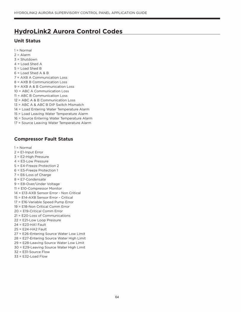
64
HYDROLINK2 AURORA SUPERVISORY CONTROL PANEL APPLICATION GUIDE
Unit Status
Compressor Fault Status
1 = Normal
2 = Alarm
3 = Shutdown
4 = Load Shed A
5 = Load Shed B
6 = Load Shed A & B
7 = AXB A Communication Loss
8 = AXB B Communication Loss
9 = AXB A & B Communication Loss
10 = ABC A Communication Loss
11 = ABC B Communication Loss
12 = ABC A & B Communication Loss
13 = ABC A & ABC B DIP Switch Mismatch
14 = Load Entering Water Temperature Alarm
15 = Load Leaving Water Temperature Alarm
16 = Source Entering Water Temperature Alarm
17 = Source Leaving Water Temperature Alarm
1 = Normal
2 = E1-Input Error
3 = E2-High Pressure
4 = E3-Low Pressure
5 = E4-Freeze Protection 2
6 = E5-Freeze Protection 1
7 = E6-Loss of Charge
8 = E7-Condensate
9 = E8-Over/Under Voltage
11 = E10-Compressor Monitor
14 = E13-AXB Sensor Error - Non Critical
15 = E14-AXB Sensor Error - Critical
17 = E16-Variable Speed Pump Error
19 = E18-Non Critical Comm Error
20 = E19-Critical Comm Error
21 = E20-Loss of Communications
22 = E21-Low Loop Pressure
24 = E23-HA1 Fault
25 = E24-HA2 Fault
27 = E26-Entering Source Water Low Limit
28 = E27-Entering Source Water High Limit
29 = E28-Leaving Source Water Low Limit
30 = E29-Leaving Source Water High Limit
32 = E31-Source Flow
33 = E32-Load Flow
HydroLink2 Aurora Control Codes

65
HYDROLINK2 AURORA SUPERVISORY CONTROL PANEL APPLICATION GUIDE
HMI Reloading/Rebooting ProcedureThe following document should be referenced if the HydroLink 2 HMI tablets do not connect and communicate properly to
the HydroLink 2 Controllers. This will guide you through the process of reconfiguring the router and the HMI.
1. Power on the tablet by pressing and holding the power button until the tablet turns on.
2. If the tablet connects to the HydroLink 2 Supervisory Controller, the following steps should be skipped. If it does not
connect, the following screens may be displayed.
Fails to connect to wireless access point1. Make sure the switch on the bottom of the router is set to “AP-Router”.
2. Make sure the Micro SD card is inserted into the tablet.
a. *Do not proceed if Micro SD Card is not inserted.
3. Swiping up from the bottom of the screen will make a tool bar appear at the bottom of the screen, use the“ “ button
to navigate to the tablets home page.
a. Press the Apps button on the home page to navigate to the Apps page.
b. On the Apps page, locate the HydroLink 2 app and press and hold the icon until it can be uninstalled by
moving it to the trash can on the top of the page, and confirm the uninstall.
c. Follow the same steps to uninstall the 123Go app if it is installed on the tablet.
d. Return to the Home page.
4. From the home screen press the File manager Icon and navigate to the following location:
5. Installing Applications a. Select “File Manager” from the home screen. b. Select “SD Card” c. Select “HydroLink 2” d. Select 123GOXX-XX.apk. The XX-XX is the version number ex. 01-00. i. When popup appears select “NEXT”, then select “INSTALL”.
ii. Once the install is complete, select “OPEN”.

66
HYDROLINK2 AURORA SUPERVISORY CONTROL PANEL APPLICATION GUIDE
HMI Reloading/Rebooting Procedure cont.6. Router Setup will begin automatically.
a. Follow on-screen prompts for Router Setup.
i. Once the tablet is connected to the router, the Factory Initialization screen will be displayed.
ii. Wait for HMI popup.
1. Select “NEXT”
2. Select “INSTALL”
3. Select “ACCEPT”
4. Once App is installed select “DONE”
iii. Doc View popup
1. Select “INSTALL”
2. Select “DONE”
3. Screen should turn green
4. Touch anywhere on the green screen.
5. The 123 Go prompt will appear asking if you want to uninstall.
6. Select “OK”
7. Once finished press at “ “at the bottom of screen to return to the HOME Screen
7. Setup Tablets Home Screen
a. Press the Apps button that is in the bottom center of the screen. The apps button is a round white button with
six dots.
b. Locate the “Doc View” icon. Press and hold the “Doc View” icon until the home screen and drop the icon onto
the home screen.
c. Repeat this process with the “HMI” app.
d. Leave the File Manager icon on the home screen.
8. Start the HMI App by pressing it one time.

67
HYDROLINK2 AURORA SUPERVISORY CONTROL PANEL APPLICATION GUIDE
BACnet PointslistsTR
UE
FALS
E
1M
SVSY
S_Sy
stem
Mod
eR/
WC
oolin
g O
nly
-Se
lect
ion
of c
urre
nt o
pera
ting
mod
e fo
r bot
h he
ader
rack
and
non
-hea
der r
ack
appl
icat
ions
.
1BV
SYS_
Syst
emEn
able
R/W
Dis
able
-A
llow
s su
perv
isor
to e
nabl
e/di
sabl
e un
its a
ccor
ding
to ru
ntim
e &
cap
acity
. En
able
s (T
rue)
or D
isab
les
(Fal
se) s
yste
m o
pera
tion.
Whe
n th
is s
ettin
g is
dis
able
d th
e co
mpr
esso
r out
puts
will
not
be
activ
ated
exc
ept f
or m
anua
l ove
rrid
e op
erat
ion.
Enab
leD
isab
le
2BV
SYS_
EmSh
utdo
wn
R/W
Nor
mal
-En
able
(Tru
e) o
r Dis
able
(Fal
se) E
mer
genc
y Sh
utdo
wn.
Shut
dow
nN
orm
al
3BV
SYS_
Syst
emM
aint
enan
eR
Nor
mal
-Pr
ovid
es a
n al
arm
that
will
trig
ger e
very
90
cale
ndar
day
s, to
rem
ind
owne
r to
chec
k an
d cl
ean
stra
iner
s. T
his
requ
ires
a h
ard
rese
t fro
m th
e H
MI.
Ala
rmN
orm
al
4BV
SYS_
Tem
pSen
sorF
ailu
reR
Nor
mal
-Pr
ovid
es a
n al
arm
if a
ny h
eade
r rac
k te
mpe
ratu
re s
enso
r be
out o
f ran
ge o
r offl
ine.
(T
rue(
Ala
rm) i
f sen
sor o
ut o
f ran
ge a
nd F
alse
(Nor
mal
) if s
enso
rs a
re w
ithin
rang
e)A
larm
Nor
mal
5BV
SYS_
Hig
hHea
derT
emp
RN
orm
al-
This
poi
nt w
ill m
onito
r the
ent
erin
g he
ader
flui
d te
mpe
ratu
re.
True
(Ala
rm) i
f sen
sor
out o
f ran
ge a
nd te
mp
is to
o H
IGH
, and
a F
alse
(Nor
mal
) if s
enso
rs a
re w
ithin
rang
e).
Ala
rmN
orm
al
6BV
SYS_
Low
Hea
derT
emp
RN
orm
al-
This
poi
nt w
ill m
onito
r the
ent
erin
g he
ader
flui
d te
mpe
ratu
re.
True
(Ala
rm) i
f sen
sor
out o
f ran
ge a
nd te
mp
is to
o LO
W, a
nd a
Fal
se (N
orm
al)
Ala
rmN
orm
al
7BV
SYS_
Cap
acity
Lim
it_En
able
R/W
Dis
able
-Th
is v
aria
ble
will
act
ivat
e an
d di
sabl
e th
e C
apac
ity L
imit
func
tions
.En
able
Dis
able
1A
VSY
S_C
oldS
etpo
int
R/W
45°F
2A
VSY
S_H
otSe
tpoi
ntR/
W12
5°F
3A
VSY
S_H
otSe
tpoi
ntRe
set
R/W
0°F
4A
VSY
S_C
oldS
etpo
intR
eset
R/W
0°F
5A
VSY
S_Sy
stem
Cap
acity
Lim
itR/
W-
%Th
is w
ill li
mit
the
capa
city
of t
he s
yste
m fr
om 1
00%
dow
n to
20%
(dep
endi
ng o
n nu
mbe
r of u
nits
in s
yste
m) b
y di
sabl
ing
Uni
ts a
llow
ed to
run.
Typ
ical
ly u
sed
to li
mit
ener
gy c
onsu
mpt
ion
duri
ng p
eak
hour
s.
6A
VSY
S_A
ctiv
eCap
acity
R10
0%
7A
VSY
S_Sy
stem
Tota
lCur
rent
R-
A
8A
VSY
S_Ef
fect
iveC
oldS
PR
45°F
9A
VSY
S_Ef
fect
iveH
otSP
R12
5°F
10A
VSY
S_Sy
stem
Uni
tCou
ntR
--
A to
tal c
ount
of u
nits
that
are
pip
ed to
geth
er to
mak
e up
(1) s
yste
m fo
r mor
e sy
stem
cap
acity
con
trol
.
Stat
e Te
xtO
bjec
t ID
Obj
ect
Type
Obj
ect N
ame
Rea
d /
Wri
teD
efau
lt V
alue
Uni
tsD
escr
iptio
n
Syst
em P
oint
s
Coo
ling
set p
oint
use
d fo
r sys
tem
cap
acity
con
trol
in c
oolin
g m
odes
.
Allo
ws
a re
set v
alue
com
man
d ra
ngin
g fr
om {
-6 to
6 }
to re
set t
he s
yste
m h
otw
ater
set
poin
t.
Allo
ws
a re
set v
alue
com
man
d ra
ngin
g fr
om {
-6 to
6 }
to re
set t
he s
yste
m c
oldw
ater
set
poin
t.
*Pos
sibl
e va
lues
are
list
ed b
elow
.
* A
lso
see
"Ope
ratin
g Sy
stem
Mod
es
Base
d on
Hea
der R
ack
Sele
ctio
n."
^See
tabl
e at
end
of l
ist f
or e
xam
ples
.
Hea
ting
set p
oint
use
d fo
r sys
tem
cap
acity
con
trol
in h
eatin
g m
odes
.
The
perc
enta
ge o
f uni
ts th
at a
re a
ctiv
ely
enab
led
and
runn
ing.
Tota
l am
pera
ge o
f ope
ratin
g co
mpr
esso
rs in
the
syst
em.
A c
ombi
natio
n of
the
Col
dSet
poin
t, an
d th
e C
oldS
etpo
intR
eset
, use
d fo
r sys
tem
cap
acity
con
trol
in c
oolin
g m
odes
..
A c
ombi
natio
n of
the
Hot
Setp
oint
, and
the
Hot
Setp
oint
Rese
t, us
ed fo
r sys
tem
cap
acity
con
trol
in h
eatin
g m
odes
..

68
HYDROLINK2 AURORA SUPERVISORY CONTROL PANEL APPLICATION GUIDE
BACnet Pointslists cont.
TRU
EFA
LSE
Stat
e Te
xtO
bjec
t ID
Obj
ect
Type
Obj
ect N
ame
Rea
d /
Wri
teD
efau
lt V
alue
Uni
tsD
escr
iptio
n
101
MSV
Ch1
_Ala
rmSt
atus
R-
-D
ispl
ays t
he c
urre
nt o
vera
ll un
it fa
ult s
tatu
s.
102
MSV
Ch1
_Uni
tSta
tus
R-
-D
ispl
ays t
he c
urre
nt o
vera
ll un
it op
erat
ing
stat
us
103
MSV
Ch1
_Com
pALo
ckou
tSta
tus
R-
-M
ost r
ecen
t fau
lt de
tect
ed b
y A
BC A
.
104
MSV
Ch1
_Com
pBLo
ckou
tSta
tus
R-
-M
ost r
ecen
t fau
lt de
tect
ed b
y A
BC B
.
101
BVC
h1_E
nabl
eMan
ualO
verr
ide
RO
ff-
Stat
us o
f Loc
al M
anua
l Ove
rrid
e at
uni
t.En
able
(On)
Dis
able
(Off)
102
BVC
h1_I
soV
alve
Stat
usR
Clo
sed
-St
atus
of A
BC A
acc
esso
ry re
lay
outp
ut.
Ope
nC
lose
d
101
AV
Ch1
_Uni
tRun
Tim
eR
-hr
Ana
log
Val
ue =
201
Bina
ry V
alue
= 2
01-2
02
Ana
log
Val
ue =
301
Bina
ry V
alue
= 3
01-3
02
Ana
log
Val
ue =
401
Bina
ry V
alue
= 4
01-4
02
Ana
log
Val
ue =
501
Bina
ry V
alue
= 5
01-5
02
** P
ossi
ble
valu
es a
re li
sted
bel
ow.
***
Poss
ible
val
ues
are
liste
d be
low
.
Com
pres
sor A
& c
ompr
esso
r B o
pera
ting
hour
s co
mbi
ned.
Mul
ti St
ate
Val
ue =
401
-404
Mul
ti St
ate
Val
ue =
201
-204
Chi
ller 1
Poi
nts
****
Pos
sibl
e va
lues
are
list
ed b
elow
.
****
Pos
sibl
e va
lues
are
list
ed b
elow
.
Chi
ller 2
Mul
ti St
ate
Val
ue =
301
-304
Mul
ti St
ate
Val
ue =
501
-504
Chi
ller 5
Chi
ller 2
- 5
will
all
have
the
sam
e po
ints
as
Chi
ller 1
.
Chi
ller 3
Chi
ller 4
TRU
EFA
LSE
Stat
e Te
xtO
bjec
t ID
Obj
ect
Type
Obj
ect N
ame
Rea
d /
Wri
teD
efau
lt V
alue
Uni
tsD
escr
iptio
n
1101
AV
HD
R_H
otBy
Pass
_Vlv
R-
%
1102
AV
HD
R_C
oldB
yPas
s_V
lvR
-%
1103
AV
HD
R_N
etEn
ergy
ByPa
ss_V
lvR
-%
1104
AV
HD
R_Sr
cHot
Out
let_
Tem
pR
-°F
1105
AV
HD
R_Sr
cHot
Inle
t_Te
mp
R-
°F
1106
AV
HD
R_Lo
adC
oldO
utle
t_Te
mp
R-
°F
1107
AV
HD
R_Lo
adC
oldI
nlet
_Tem
pR
-°F
1108
AV
HD
R_N
etEn
ergy
Out
let_
Tem
pR
-°F
1109
AV
HD
R_N
etEn
ergI
nlet
_Tem
pR
-°F
1101
BVRe
frig
eran
tMon
itorA
larm
RN
orm
al-
Mon
itors
the
Refr
iger
ant L
eak
Det
ectio
n sy
stem
(pro
vide
d by
oth
ers)
and
will
sen
d a
True
(Ala
rm)/F
alse
(Nor
mal
) ala
rm if
trig
gere
d.A
larm
Nor
mal
Syst
ems
head
er ra
ck g
eo w
ater
out
let t
empe
ratu
re.
Syst
ems
head
er ra
ck g
eo w
ater
inle
t tem
pera
ture
.
Syst
ems
head
er ra
ck h
ot/s
ourc
e w
ater
inle
t tem
pera
ture
.
Syst
ems
head
er ra
ck c
old/
load
wat
er o
utle
t tem
pera
ture
.
Syst
ems
head
er ra
ck h
ot/s
ourc
e w
ater
out
let t
empe
ratu
re.
Syst
ems
head
er ra
ck c
old/
load
wat
er in
let t
empe
ratu
re.
Syst
ems
head
er ra
ck g
eo w
ater
byp
ass
valv
e.
(Pro
port
iona
l with
6pi
pe 3
way
val
ves d
epen
ding
on
mod
e).
Syst
ems
head
er ra
ck c
old/
load
wat
er b
ypas
s va
lves
. (P
ropo
rtio
nal w
ith lo
ad/e
vapo
rato
r 6pi
pe 3
way
val
ves)
.
Hea
der R
ack
Onb
oard
34-
IO
Syst
ems
head
er ra
ck h
ot/s
ourc
e w
ater
byp
ass
valv
e. (P
ropo
rtio
nal w
ith s
ourc
e/co
nden
ser 6
pipe
3w
ay v
alve
s).

69
HYDROLINK2 AURORA SUPERVISORY CONTROL PANEL APPLICATION GUIDE
TRU
EFA
LSE
Stat
e Te
xtO
bjec
t ID
Obj
ect
Type
Obj
ect N
ame
Rea
d /
Wri
teD
efau
lt V
alue
Uni
tsD
escr
iptio
n
*M
SV-1
SYS_
Mod
eR/
W-
-
**
MSV
- 10
1
201
30
1
401
50
1
Ala
rmSt
atus
R-
-
Ala
rm S
tatu
s
Syst
em M
ode
Dis
play
s the
cur
rent
ove
rall
unit
faul
t sta
tus.
Pos
sibl
e va
lues
are
:1
= N
orm
al2
= A
larm
3 =
Shut
dow
n4
= Lo
ad S
hed
A5
= Lo
ad S
hed
B6
= Lo
ad S
hed
A &
B7
= A
XB A
Com
mun
icat
ion
Loss
8 =
AXB
B C
omm
unic
atio
n Lo
ss9
= A
XB A
& B
Com
mun
icat
ion
Loss
10 =
ABC
A C
omm
unic
atio
n Lo
ss11
= A
BC B
Com
mun
icat
ion
Loss
12 =
ABC
A &
B C
omm
unic
atio
n Lo
ss13
= A
BC A
& A
BC B
DIP
Sw
itch
Mis
mat
ch14
= L
oad
Ente
ring
Wat
er T
empe
ratu
re A
larm
15 =
Loa
d Le
avin
g W
ater
Tem
pera
ture
Ala
rm16
= S
ourc
e En
teri
ng W
ater
Tem
pera
ture
Ala
rm17
= S
ourc
e Le
avin
g W
ater
Tem
pera
ture
Ala
rm
Poss
ible
val
ues
are:
1 =
Syst
em O
ff- w
ith Is
olat
ion
valv
es o
pen
2 =
Coo
ling
only
- (S
tand
ard)
3 =
Hea
ting
only
- (S
tand
ard)
4 =
Aut
o fu
ll bu
ildin
g - (
6-Pi
pe H
eade
r Rac
k)5
= Fu
ll bu
ildin
g - (
Stan
dard
)6
= Pr
imar
y co
olin
g - (
6-Pi
pe H
eade
r Rac
k)7
= Pr
imar
y he
atin
g - (
6-Pi
pe H
eade
r Rac
k)8
= Sy
stem
Off-
with
Isol
atio
n va
lves
clo
sed
BACnet Pointslists cont.

70
HYDROLINK2 AURORA SUPERVISORY CONTROL PANEL APPLICATION GUIDE
TRU
EFA
LSE
Stat
e Te
xtO
bjec
t ID
Obj
ect
Type
Obj
ect N
ame
Rea
d /
Wri
teD
efau
lt V
alue
Uni
tsD
escr
iptio
n
***
MSV
- 10
2
202
30
2
402
50
2
Uni
t_St
atus
R-
-
Uni
t Sta
tus
Dis
play
s the
cur
rent
ove
rall
unit
oper
atin
g st
atus
. Po
ssib
le v
alue
s ar
e:1
= St
andb
y3
= Si
ngle
Com
pres
sor C
oolin
g4
= Bo
th C
ompr
esso
rs C
oolin
g6
= Si
ngle
Com
pres
sor H
eatin
g7
= Bo
th C
ompr
esso
rs H
eatin
g10
= E
mer
genc
y Sh
utdo
wn
11 =
Loa
d Sh
ed12
= L
ocko
ut A
13 =
Tes
t Mod
e15
= L
ocko
ut B
18 =
Sin
gle
Com
pres
sor w
/Loc
kout
19 =
Ful
l Loc
kout
31 =
Sou
rce
Flow
Sw
itch
Faul
t32
= L
oad
Flow
Sw
itch
Faul
t33
= L
oad
& S
ourc
e Fl
ow S
witc
h Fa
ult
BACnet Pointslists cont.
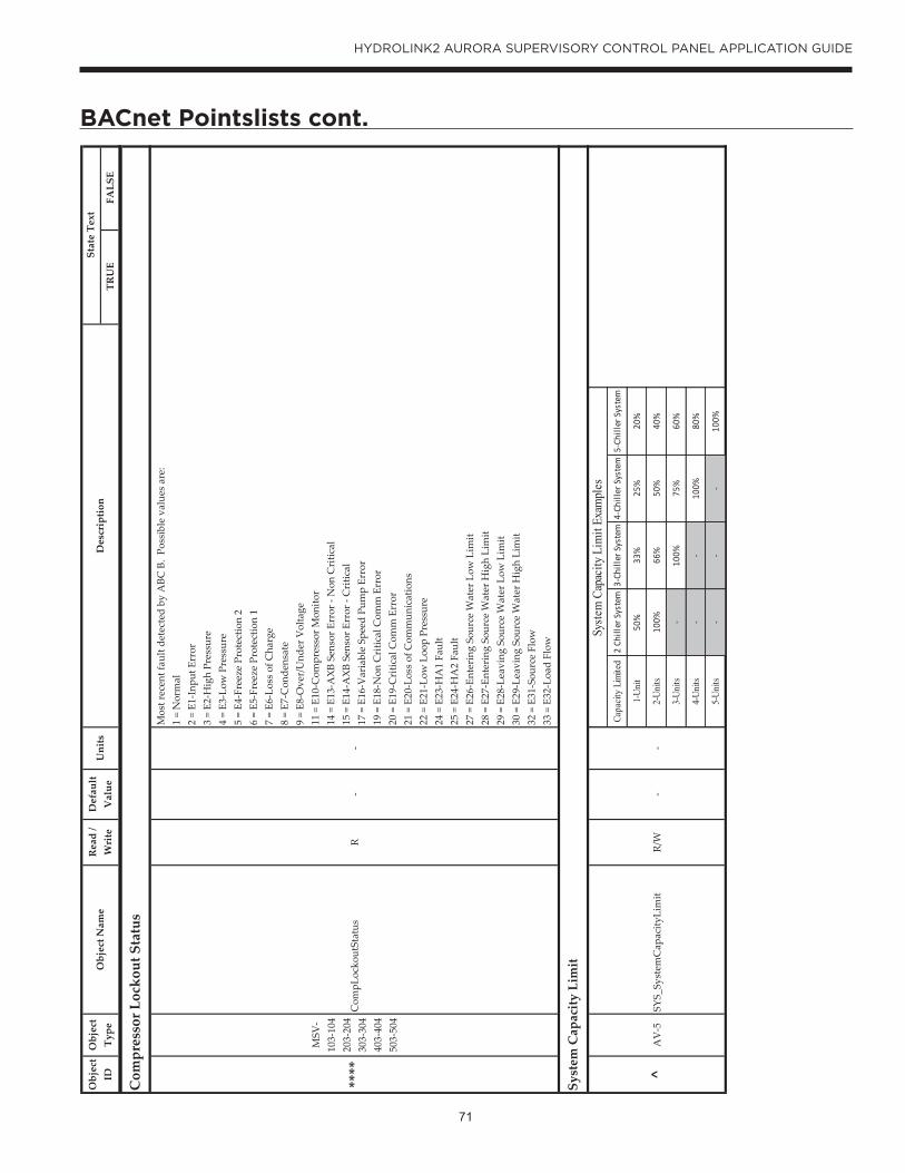
71
HYDROLINK2 AURORA SUPERVISORY CONTROL PANEL APPLICATION GUIDE
TRU
EFA
LSE
Stat
e Te
xtO
bjec
t ID
Obj
ect
Type
Obj
ect N
ame
Rea
d /
Wri
teD
efau
lt V
alue
Uni
tsD
escr
iptio
n
****
MSV
- 10
3-10
4
203-
204
30
3-30
4
403-
404
50
3-50
4
Com
pLoc
kout
Stat
usR
--
^A
V-5
SYS_
Syst
emC
apac
ityLi
mit
R/W
--
Syst
em C
apac
ity L
imit
Com
pres
sor L
ocko
ut S
tatu
s
Mos
t rec
ent f
ault
dete
cted
by
ABC
B.
Poss
ible
val
ues
are:
1 =
Nor
mal
2 =
E1-I
nput
Err
or3
= E2
-Hig
h Pr
essu
re4
= E3
-Low
Pre
ssur
e5
= E4
-Fre
eze
Prot
ectio
n 2
6 =
E5-F
reez
e Pr
otec
tion
17
= E6
-Los
s of
Cha
rge
8 =
E7-C
onde
nsat
e9
= E8
-Ove
r/U
nder
Vol
tage
11 =
E10
-Com
pres
sor M
onito
r14
= E
13-A
XB S
enso
r Err
or -
Non
Cri
tical
15 =
E14
-AXB
Sen
sor E
rror
- C
ritic
al17
= E
16-V
aria
ble
Spee
d Pu
mp
Erro
r19
= E
18-N
on C
ritic
al C
omm
Err
or20
= E
19-C
ritic
al C
omm
Err
or21
= E
20-L
oss
of C
omm
unic
atio
ns22
= E
21-L
ow L
oop
Pres
sure
24 =
E23
-HA
1 Fa
ult
25 =
E24
-HA
2 Fa
ult
27 =
E26
-Ent
erin
g So
urce
Wat
er L
ow L
imit
28 =
E27
-Ent
erin
g So
urce
Wat
er H
igh
Lim
it29
= E
28-L
eavi
ng S
ourc
e W
ater
Low
Lim
it30
= E
29-L
eavi
ng S
ourc
e W
ater
Hig
h Li
mit
32 =
E31
-Sou
rce
Flow
33 =
E32
-Loa
d Fl
ow
Capa
city
Limi
ted
2 Ch
iller
Sys
tem
3-Ch
iller
Sys
tem
4-Ch
iller
Sys
tem
5-Ch
iller
Sys
tem
1-Un
it 50
%33
%25
%20
%
2-Un
its10
0%66
%50
%40
%
3-Un
its-
100%
75%
60%
4-Un
its
--
100%
80%
5-Un
its-
--
100%
Syste
m C
apac
ity L
imit
Exam
ples
BACnet Pointslists cont.
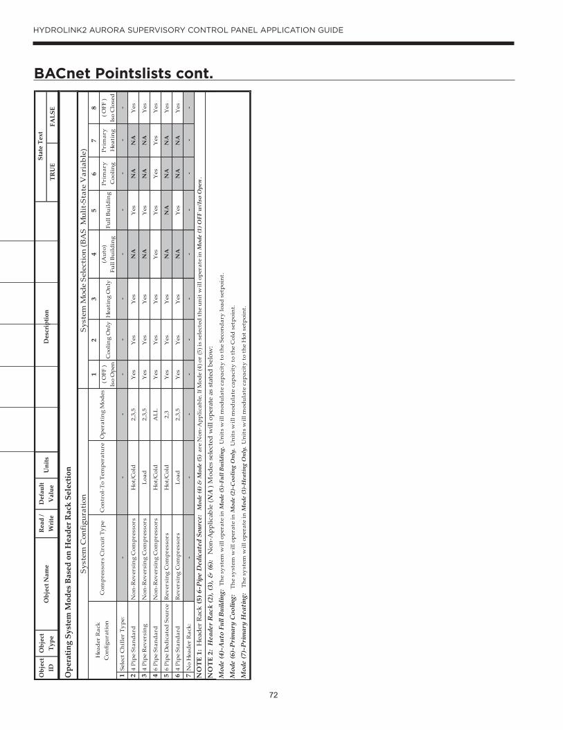
72
HYDROLINK2 AURORA SUPERVISORY CONTROL PANEL APPLICATION GUIDE
TRU
EFA
LSE
Stat
e Te
xtO
bjec
t ID
Obj
ect
Type
Obj
ect N
ame
Rea
d /
Wri
teD
efau
lt V
alue
Uni
tsD
escr
iptio
n
Ope
ratin
g Sy
stem
Mod
es B
ased
on
Hea
der R
ack
Sele
ctio
n
12
34
56
78
( OFF
)
Iso
Op
enC
ooli
ng
On
lyH
eati
ng
On
ly(A
uto
)
Full
Bu
ild
ing
Full
Bu
ild
ing
Pri
mar
y
Coo
lin
gP
rim
ary
H
eati
ng
( OFF
)
Is
o C
lose
d
1Se
lect
Ch
ille
r T
yp
e:-
--
--
--
--
--
24
Pip
e St
and
ard
Non
-Rev
ersi
ng
Com
pre
ssor
sH
ot/C
old
2,3,
5Y
esY
esY
esN
AY
esN
AN
AY
es
34
Pip
e R
ever
sin
gN
on-R
ever
sin
g C
omp
ress
ors
Loa
d2,
3,5
Yes
Yes
Yes
NA
Yes
NA
NA
Yes
46
Pip
e St
and
ard
Non
-Rev
ersi
ng
Com
pre
ssor
sH
ot/C
old
AL
LY
esY
esY
esY
esY
esY
esY
esY
es
56
Pip
e D
edic
ated
Sou
rce
Rev
ersi
ng
Com
pre
ssor
sH
ot/C
old
2,3
Yes
Yes
Yes
NA
NA
NA
NA
Yes
64
Pip
e St
and
ard
Rev
ersi
ng
Com
pre
ssor
sL
oad
2,3,
5Y
esY
esY
esN
AY
esN
AN
AY
es
7N
o H
ead
er R
ack:
--
--
--
--
--
-
Mod
e (7
)-P
rim
ary
Hea
ting
: T
he
syst
em w
ill o
per
ate
in M
ode
(3)-
Hea
ting
Onl
y. U
nit
s w
ill m
odu
late
cap
acit
y t
o th
e H
ot s
etp
oin
t.
Syst
em C
onfi
gura
tion
Syst
em M
ode
Sele
ctio
n (B
AS
Mul
it-S
tate
Var
iabl
e)
Mod
e (4
)-A
uto
Full
Bui
ldin
g: T
he
syst
em w
ill o
per
ate
in M
ode
(5)-
Full
Bui
ldin
g. U
nit
s w
ill m
odu
late
cap
acit
y t
o th
e Se
con
dar
y lo
ad s
etp
oin
t.
Mod
e (6
)-P
rim
ary
Coo
ling:
T
he
syst
em w
ill o
per
ate
in M
ode
(2)-
Coo
ling
Onl
y. U
nit
s w
ill m
odu
late
cap
acit
y t
o th
e C
old
set
poi
nt.
NO
TE
2: H
eade
r R
ack
(2),
(3),
& (6
): N
on-A
pplic
able
(N
A) M
odes
sel
ecte
d w
ill o
pera
te a
s st
ated
bel
ow:
NO
TE
1: H
eade
r R
ack
(5) 6
-Pip
e D
edic
ated
Sou
rce:
Mod
e (4
) & M
ode
(5)
are
Non
-Ap
pli
cab
le. I
f Mod
e (4
) or
(5) i
s se
lect
ed t
he
un
it w
ill o
per
ate
in M
ode
(1) O
FF w
/Iso
Ope
n.
Hea
der
Rac
k C
onfi
gura
tion
Com
pre
ssor
s C
ircu
it T
yp
eC
ontr
ol-T
o T
emp
erat
ure
Op
erat
ing
Mod
es
BACnet Pointslists cont.
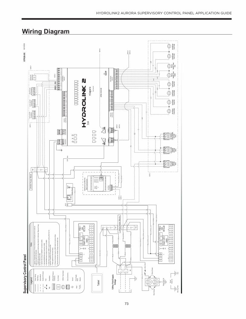
73
HYDROLINK2 AURORA SUPERVISORY CONTROL PANEL APPLICATION GUIDE
Wiring Diagram
LON
DAT
ALO
N St
atus
MS/
TP TK
NM
S/TP
PKT + _
LONLON
PowerGNDGND
Babe
lBu
ster
2
NOTE
1
USB
PRI
SEC
RS-4
85-1
S
- +
S
- +
RS-4
85-2
A1A2
A3A4
A5A6
A7A8
CC
CC
U1
U2
U3
U4
U5
U6
U7
CC
CC
U8
U9
U12
U13
U14
U15
CC
CC
U16
U10
U11
D1
D4
D5
D6
D7
CC
CC
D8
D2
D3
D9
CD
1024
VAC/
DC~ -~
+
SHLD
LxHLxL
Hy
dr
oLin
k 2
niag
ara
534
JEN
E-EG
534
Fram
ewor
k
TxR
xTx
Rx
UN
IVER
SIAL
IN
PUTS
ANAL
OG
O
UTP
UTS
D1
D2
D3
D4
D5
D5
DIG
ITAL
OU
TPU
TS
Bras
s Scr
ews
Supe
rviso
ry C
ontro
l Pan
el No
tes
L N G
120V
ac F
ield S
uppl
yVo
ltage
PB1
1 21
CAT5
Cab
le
Silve
r Scr
ews
Gree
n/Ye
llow
(8)
TT
TT
TT
NET
ENER
GY
LOOP
HEA
DER
BYPA
SSVa
lve
HOT
LOOP
HE
ADER
BYPA
SSVa
lve
COLD
LOO
P HE
ADER
BY
PASS
Valve
3. Op
tiona
l field
wirin
g fo
r Bac
Net I
/P c
onne
ction
to B
AS.
2. RS
485
field
wire
d co
nnec
tion
shou
ld be
dais
y cha
ined t
o ch
iller b
ank.
Requ
ires 2
2 awg
sh
ielde
d tw
isted
pai
r cab
le.
0-10
Com
24V
0-10
Com
24V
0-10
Com
24V
2 31 PB2
6. 24
Vdc P
ower
supp
ly bo
ard
1(PS
B-1)
cann
ot po
wer a
nyth
ing ot
her t
han
the
Hydr
olink
2, Hy
droL
ink2
I/O m
odule
s and
HM
I.
UN
IVER
SIAL
IN
PUTS
TT
D6
D7
D8
D9
D10
POW
ER S
UPPL
Y BO
ARD
RC
23
41
34
52
1
P2P1
23
41
34
52
1
P4P3
GND
24V P5
+5V
+24Vdc
GND
USB
USB
5A
Facto
ry W
iring
Field
Wirin
g
Optio
nal B
lock
Grou
nd
Lege
nd
Outsi
de o
f Enc
losur
e
Powe
rbloc
kPB
2
Diffe
rentia
l Pres
sure
Tran
sduc
er
Dry C
onta
ct
T10
KOhm
Tem
p Se
nsor
0-10
Com
24V
Valve
Con
necti
on
F1Fu
se
1. Op
tiona
l Tem
pera
ture
sens
ors,
Pres
sure
tran
sduc
ers a
nd B
ypas
s val
ves l
ocat
ed o
n he
ader
rack
nee
d to
be
field
wire
d.
4. Op
tiona
l RS4
85 fie
ld wi
red co
nnec
tion t
o BAS
.
97P8
38-X
X8/
21/20
18
7. Fi
eld su
pplie
d an
d fie
ld wi
red
devic
e.
POW
ER S
UPPL
Y BO
ARD
RC
23
41
34
52
1
P2P1
23
41
34
52
1
P4P3
GND
24V P5
+5V
+24VDC
GND
USB
USB
5A
Powe
r Sup
ply
Boar
dPS
B-1
PSB-
1
PSB-
2
Resis
tor
8. Pr
essu
re tr
ansd
ucer
s req
uire
a 25
0Ω re
sisto
r be
wire
d as s
hown
.
5. Op
tiona
l field
wire
d Lon
Wor
ks co
nnec
tion t
o the
BAS
.
Transformer
Blac
k/W
hite
Transformer
Whi
te (7
)
Blac
k (6
)
Blac
k
Whi
te
Whi
te
Blac
k
Yello
w
Table
t
2 31 PB1
Blac
k/W
hite
Yello
w
Blac
k (1
0)
Yello
w (1
1)
Yello
w (+
24Va
c) Blac
k (2
4Vac
com
)
Red
(+24
Vdc)
Blac
k (2
4Vdc
com
)
Blac
k (2
4Vdc
com
)
Red
(+24
Vdc)
9VD
C Ad
apto
r
Wire
less
Rout
erPowe
r
Red
(+24
Vdc)
24VD
C Po
wer
Blo
ck
Blac
k (2
4Vdc
com
)
2 31PB3
Refr
iger
ant
Mon
itor
ing
A1
C
C
A2
A3
U1
CU
2U
3C
U4 U
5C
U6
U7
CU
8
9Vdc
Blac
k (2
4Vdc
com
)
Red
(+24
Vdc)
NOTE
5
Opt
iona
l Lon
Wor
ks
BAS
Conn
ectio
n
NOTE
1
Gree
n/Ye
llow
(9)
Mou
nting
Pla
teDo
or
24Va
c Pow
er B
lock
s
NOTE
2
NOTE
3
NOTE
4
NOTE
7
NOTE
8
9. Re
quire
s twi
sted
pair
shiel
ded 2
2awg
com
mun
icatio
n wi
re.
NOTE
9
NOTE
9
NOTE
9
V+
IOU
T V
OU
T C
OM
ZER
O V
+ IO
UT
VO
UT
CO
M Z
ERO
V+
IOU
T V
OU
T C
OM
ZE
RO
Hot L
oop
DP
Tran
sduc
erCo
ld L
oop
DP
Tran
sduc
erSo
urce
Loop
DP
Tra
nsdu
cer
V+
IO
UT
V
OU
T
CO
M
ZER
O

74
HYDROLINK2 AURORA SUPERVISORY CONTROL PANEL APPLICATION GUIDE
Port Layout

75
HYDROLINK2 AURORA SUPERVISORY CONTROL PANEL APPLICATION GUIDE
System Confi gurationThere are several different modes of operation depending on the type of system present. Below we discuss the different header rack confi guration and the system modes of operation.
Types of Header Racks1 = Header Rack Not Confi gured 2 = 4 Pipe Standard - (Non-Reversing Compressors)3 = 4 Pipe Reversing - (Non-Reversing Compressors)4 = 6 Pipe Standard - (Non-Reversing Compressors)5 = 6 Pipe Dedicated Source - (Reversing Compressors)6 = 4 Pipe Standard - (Reversing Compressors)7 = No Header Rack
Modes of operation for units with Header Racks 1 = Off with isolation valves open2 = Cooling Only 3 = Heating Only4 = Auto Full Building - (6-Pipe Only)5 = Full Building6 = Primary Cooling - (6-Pipe Only)7 = Primary Heating - (6-Pipe Only) 8 = Off with isolation valves closed

76
HYDROLINK2 AURORA SUPERVISORY CONTROL PANEL APPLICATION GUIDE
Revision GuidePages: Description: Date: By:
All Document Created 19 Oct 2017 MA

77
HYDROLINK2 AURORA SUPERVISORY CONTROL PANEL APPLICATION GUIDE
Notes

Product: HydroLink2 Aurora Supervisory Control
Document Type: Application and Troubleshooting GuidePart Number: AG1571EWRevision Date: 07/19