Hydrogen Storage and Fuel Cells - University of Chicago presentation...Hydrogen Storage and Fuel...
35
Hydrogen Storage and Fuel Cells Di-Jia Liu Argonne National Laboratory Short Course – Physics of Sustainable Energy Energy Policy Institute at The University of Chicago June 18, 2016
Transcript of Hydrogen Storage and Fuel Cells - University of Chicago presentation...Hydrogen Storage and Fuel...

Hydrogen Storage and Fuel Cells
Di-Jia Liu
Argonne National Laboratory
Short Course – Physics of Sustainable Energy
Energy Policy Institute at The University of Chicago
June 18, 2016

2
Global Primary Energy Supplies
Source: International Energy Agency - energy statistics, Sept 2006, Data compiled up to 2004
Coal, 25.1%
Nuclear, 6.5%Renewable,
13.3%
Oil, 34.3%Gas, 20.9%

Outlook of Globe Energy Demand & its Impact to
Environment
3
Fossil fuels will lead world energy consumption in decades to come
Energy Information Administration: www.eia.doe.gov/iea
IPCC Fifth Assessment 2013: http://www.ipcc.ch/index.htm
Quadrillion BTU
GHG emission causes rise of global temperature and threatens ecosystem
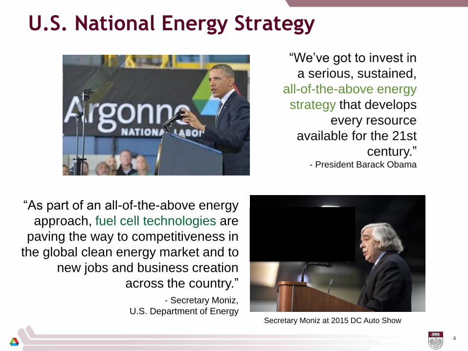
U.S. National Energy Strategy
4
“We’ve got to invest in
a serious, sustained,
all-of-the-above energy
strategy that develops
every resource
available for the 21st
century.”- President Barack Obama
“As part of an all-of-the-above energy
approach, fuel cell technologies are
paving the way to competitiveness in
the global clean energy market and to
new jobs and business creation
across the country.”
- Secretary Moniz,
U.S. Department of EnergySecretary Moniz at 2015 DC Auto Show

Transportation electrification depends critically on
next-generation power train development
Cost
Durability
Performance
Convenience
Tesla Model S – Li ion battery Toyota Mirai – hydrogen fuel cell
Factors Important to Consumer
Source: US Department of Energy, Office of Energy Efficiency and Renewable Energy

6
Current Status of Polymer Electrolyte Fuel Cells
and Future Direction for Development

Different Types of Fuel Cells
7
200-kW PAFC
Fuel Cell TypeTemperature
ApplicationsElectrolyte / Ion
Polymer Electrolyte
Membrane (PEM)
60 - 100° C Electric utility
Portable power
TransportationNafion/H+
Alkaline
(AFC)
90 – 100° C Military
SpaceKOH / OH-
Phosphoric Acid
(PAFC)
175 – 200° C Electric utility
Distributed power
TransportationH3PO4 / H+
Molten Carbonate
(MCFC)
600 – 1000° C Electric utility
Distributed power(Li,K,Na)2CO3 / CO2-
Solid Oxide
(SOFC)
600 – 1000° C Electric utility
Distributed power
APUs(Zr,Y) O2 / O-
SOFC kW Stack 2MW MCFC Plant
85-kW PEMFC
1.5-kW AFC

8
Polymer Electrolyte Membrane Fuel Cell (PEMFC)
Anode H2 2 H+ + 2 e-
Cathode O2 + 4 e- + 4 H+ 2 H2O
Membrane
Catalyst
GDLBipolar
Plate
e- e-
H2O
H2
O2
PEMFC Stack
Power density: 650 W/L
Efficiency: 50 to 60%
H+

U S DOE Fuel Cells Strategy
Reducing platinum usage to < 0.125 g/kW (or 10 g/vehicle at 80 kW rated power)
Increasing MEA durability to 5000 hours under cycling
Increasing stack power density to 0.85kW/L (or stack volume of 94L for 80kW unit)
Reducing costs of accessories, bipolar plates, air compressor, humidification, etc.
9
High
Medium
Low to Medium
Level of
Difficulty
BARRIERS NEAR TO MID-TERM LONG-TERM
700 bar tanks, composites, cryo-
compressedHydrogen Production and Delivery
Materials R&D for low pressure
storage
Non-PGM Catalysts
AEMs
Fuel Cell Cost and Durability
Hydrogen Storage
R&
D
Low-PGM catalysts , MEAs, performance
durability, components
H2 from NG/electrolysis; delivered H2, compression
H2 from renewables (PEC, biological, etc.),
pipelines, low P option
Near and mid-term research focuses
Replacing the platinum group metal (PGM) catalysts with earthly abundant materials
Improving ion conductivity and stability of alkaline electrolyte membranes
Long-term research focuses

10
The Electrode Catalyst Challenges – Demand for
Reducing or Replacing Pt Usage
Platinum and platinum group metals (PGMs) are catalysts of choice for polymer electrolyte fuel cell, posing a significant barrier for FCEV commercialization
More Pt (x3~4) is needed for cathodic oxygen reduction reaction(ORR)
New design/synthesis and/or alternative materials are underdevelopment to reduce Pt dependence
Manufactured Stack Cost Analysis
Data obtained from the presentation by TIAX on 80 kW direct H2 PEMFC at DOE 2010 Annual Merit Review
$0
$40
$80
$120
$160
2006 2008 2010 2012 2020
FC
Sys
tem
s C
os
t ($
/kW
ne
t)
Projected Transportation Fuel Cell System Cost -- (500,000 units/year)

MEA Innovation - 3M’s Nanostructured Thin Film (NSTF)
11
Conventional MEA 3M NSTF MEA
Electrolyte AnodeCathode
H2 e-
e-
H+
H2
e-
e-
O2
H2O
H2
3M’s NSTF altered conventional membrane electrode assembly morphology and significantly improved Pt usage and fuel cell performance. More need to be done in improving fuel cell robustness -

Pt Catalyst Innovation: Nanoframe Pt Alloy with
Improved Activity
12
• PtNi nanoframe catalysts synthesized through spontaneous corrosion and annealing
• Catalysts have specific and mass activities 15 and 20x those of Pt/C
• Low-loaded MEA testing shows 3x specific activity and 2x mass activity relative to DOE targets
• Further work is needed to increase performance at high current density
V. Stamenkovic, P. Yang, et. al. . Science, 343,
(2014) 1339-1343
http://www.anl.gov/

Next Generation PGM-free Catalyst – Two Innovative ANL
Approaches
13
Improving activity through rationally designed precursors – MOFs/POPs
Improving mass/charge transports through nanofibrous network
Volumetric Activity Turn-Over-Freq. x Site Density
• Argonne’s nano-fibrous network provides higher surface area and nearly exclusive micropores
• New electrode offers enhanced mass transport and charge transfer via a unique micro-macro-porous nano-network
Conventional New ANL design Conventional ANL nano-network
New nano-network architecture not only increases surface area but also site density
New 3-D precursors breaks away from 50-years of square-planar molecular approach
• Argonne introduced Metal-organic-framework & porous organic polymer as next-generation catalyst precursors
• “Support-free” and pore-former free • Uniform distribution & high active site
density

“One-Pot” Synthesis of MOF-based TM/N/C Catalysts
14
(a)
(c)
(b)
(d)
Mixing Solid State Reaction Thermolysis
ZnO
Fe complexIm mIm
eIm abIm
Different MOFsOrganic Ligands
+
TM/N/C Catalysts
0 500 1000 1500 2000 2500 3000 3500 4000
0.2
0.4
0.6
0.8
1.0
Current Density (mA cm-2)
Ce
ll P
ote
nti
al (V
)
0
200
400
600
800
1000
Po
wer
Den
sit
y (
mW
cm
-2)P = 924 mW/cm2 @ 0.38V
P = 855 mW/cm2
@ 0.47V
One-bar Oxygen
D. Zhao, J.-L. Shui, L. R. Grabstanowicz, C. Chen, S.M. Commet, T. Xu, J. Lu, and D.-J. Liu, Advanced Materials, 2014, 26, 1093–1097 (Frontpiece article)
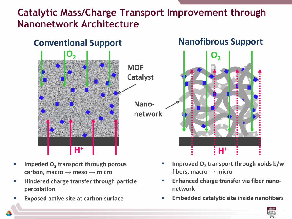
Catalytic Mass/Charge Transport Improvement through
Nanonetwork Architecture
15
Conventional Support Nanofibrous SupportO2
H+
O2
H+
Impeded O2 transport through porous carbon, macro → meso → micro
Hindered charge transfer through particle percolation
Exposed active site at carbon surface
Improved O2 transport through voids b/w fibers, macro → micro
Enhanced charge transfer via fiber nano-network
Embedded catalytic site inside nanofibers
MOF Catalyst
Nano-network
Electrospinning Conversion to catalyst Fuel cell fabrication
e-
H+
O2
H2O
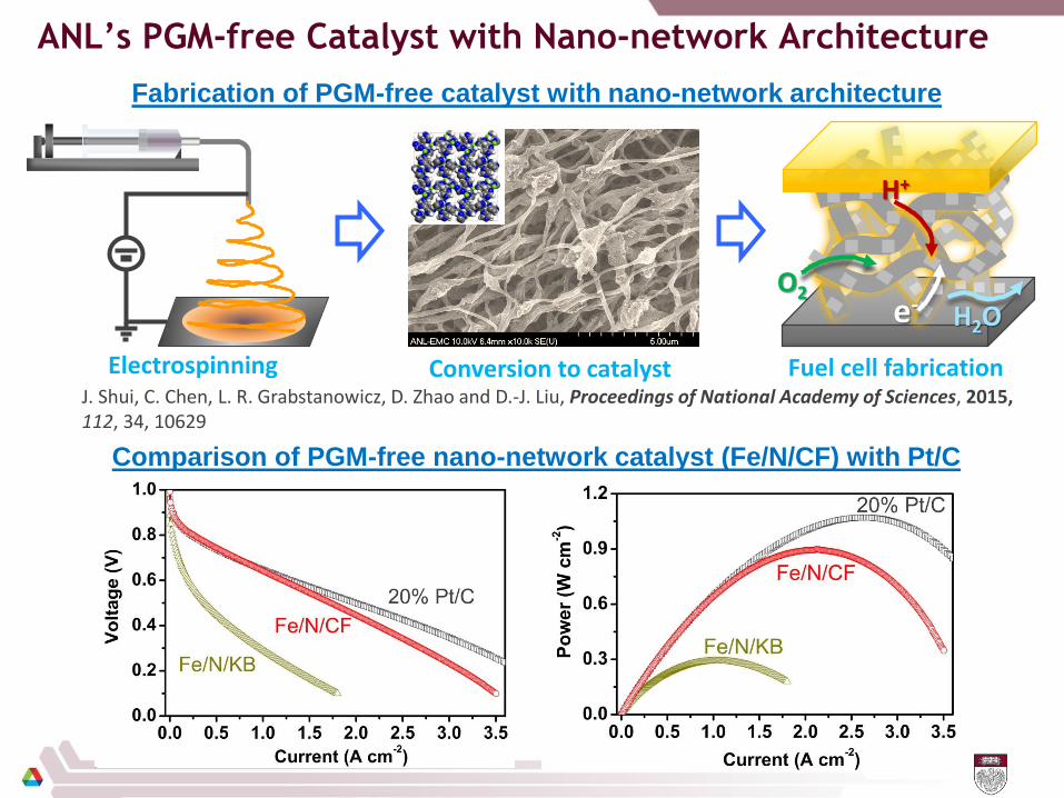
ANL’s PGM-free Catalyst with Nano-network Architecture
J. Shui, C. Chen, L. R. Grabstanowicz, D. Zhao and D.-J. Liu, Proceedings of National Academy of Sciences, 2015,112, 34, 10629
Fabrication of PGM-free catalyst with nano-network architecture
Comparison of PGM-free nano-network catalyst (Fe/N/CF) with Pt/C

17
Current Status of On-board Hydrogen Storage
and Future Direction for Development

18
Opportunities & Challenges in Hydrogen Storage for
Transportation Application
Onboard H2 production Onboard H2 storage
• Catalytic reforming of hydrocarbon fuels
• Existing fuel distribution network
• Start up time
• System efficiency (fuel utilization &CO2
reduction)
• Compressed hydrogen
• Different storage media (chemical, metallic, carbon-based, etc)
• Needs H2 distribution infrastructure
• Storage capacity issues
GasStation Fuel
StorageFuel Reformer
Fuel Cell
HydrogenChargingStation
H2
StorageFuel Cell
DOE System Targets for On-Board Hydrogen Storage for Light-Duty Vehicles
Storage Parameter Units 2017 Ultimate
System Gravimetric
Capacity
kWh/kg
(kg H2/kg system)
1.8
(0.055)
2.5
(0.075)
System Volumetric
Capacity
kWh/L
(kg H2/L system)
1.3
(0.040)
2.3
(0.070)
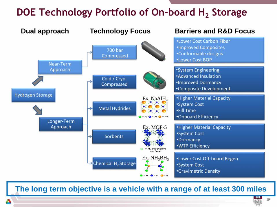
DOE Technology Portfolio of On-board H2 Storage
19
Hydrogen Storage
Near-Term Approach
700 bar Compressed
•Lower Cost Carbon Fiber•Improved Composites•Conformable designs•Lower Cost BOP
•System Engineering•Advanced Insulation•Improved Dormancy•Composite Development
Longer-Term Approach
Chemical H2 Storage
Sorbents
Metal Hydrides
Cold / Cryo-Compressed
Ex. NaAlH4
Ex. MOF-5
Ex. NH3BH3
•Higher Material Capacity•System Cost•Fill Time•Onboard Efficiency
•Higher Material Capacity•System Cost•Dormancy•WTP Efficiency
•Lower Cost Off-board Regen•System Cost•Gravimetric Density
Dual approach Technology Focus Barriers and R&D Focus
The long term objective is a vehicle with a range of at least 300 miles

20
Current Status of Hydrogen Storage Technology
0
10
20
30
40
50
60
70
0 1 2 3 4 5 6 7 8
Gravimetric Capacity (wt%)
Vo
lum
etr
ic C
ap
acit
y (
g/L
)
complex
hydride
chemical
hydride
liquid hydrogen
cryocompressed
compressed hydrogen
"Learning Demos"
Revised
DOE
system
targets
700 bar
350 barC-sorbent
2015
Ultimate
Alane Slurry
MOF-177 (250 bar)
KEY CHALLENGE: > 300-mile driving range in all vehicle platforms, without compromising passenger/cargo space, performance, or cost
Source: US DoE, Fuel Cell Technologies Program

Low Pressure H2 Storage Material Challenges
Material Type Examples Advantages Challenges
Metal Hydride
LiBH4, NaBH4, Mg(BH4)2 , etc.
High volumetric & gravimetric capacities,Highly stable at ambient temperature
Discharge-charge kinetics & time,Reversibility,Parasitic energy consumption
Chemical Hydride
NH3-BH3, C6H5-CH3, etc.
Good gravimetric & volumetric capacities, Stable at ambient temperature
Poor on-board/off-board regen,Parasitic energy consumption
Sorbent
MOF, POP, Porouscarbon, etc.
Good gravimetric capacity,Fast discharge-charge time and lower energy consumption
Cryo-compressionneeded,Unstable at ambient temperature (dormancy concern)
21
• Low pressure storage is essential in improving overall system efficiency
• Fundamental understanding and molecular manipulation are critical in
advancing next-generation storage materials
N B
H
H
H
H
H
HHB
NH
BH
NH
HB
HN

22
Sorption-based Material Challenges: Some Examples
of Next-generation Adsorbent Approaches
Design of high surface area & narrow/adjustable pore size
Incorporating “metallic” feature
Develop fundamental understanding through modeling and advanced characterization
vdW
Inte
ract
ion
Enh
ance
d v
dW
Inte
ract
ion
Re
con
form
atio
nP
ote
nti
al
H2
Kin
etic
En
erg
y
Improving storage capacity and H2 binding energy through molecular design
Metal Ion
Metal-Organic Framework (MOF) Sorbents
SolvothermalReaction
Organic Ligand
+
Porous Organic Polymer (POP) Sorbents
Contorted Core
Molecular Strut
+Crosslinking & metal doping

Improving H2 Discharge-Charge Reversibility using
Graphene Encapsulated Hydride
23
Graphene Hydrides
Nanoencapsulated hydrides
Rehydrogenation
Dehydrogenation
L. Chong, X. Zeng, W. Ding, D.-J. Liu and J. Zou, Advanced Materials, 2015, 27, 5070–5074J. Zou, L. Chong, D.-J. Liu, et. al. Science, 2016, 351 (6278), 1223
“Graphene wrapping” prevents the escape of dehydrogenation products and catalyzes the rehydrogenation during H2 charging
More innovative approaches combined with improved fundamental
understanding could ultimately resolve the current issues in H2 storage!
NaBH4 ↔ Na + B + H2, (B2H6, etc.)

24
Hydrogen Production and Distribution
Infrastructure Development

25
Borrow a Page from Gasoline Distribution?

26
DOE’s H2 Production & Delivery RD&D Portfolio
US DOE – Fuel Cell Technologies Office

H2 Infrastructure Development and Status
27
• 1,500 mi. of H2 pipeline
• >9M metric tons produced/yr
• ~50 stations (~10 public)
Nationwide California
• >~$70M awarded
• ~$100M planned through 2023
• Goal - 100 stations
H2 stations in CA
Other States
• 8-State MOU Members: CA, CT,
NY, MA, MD, OR, RI and VT
• MA, NY, CT: Preliminary plans for H2
infrastructure and FCEVs deployment
in metro centers in NE states.
• Hawai’i: Public access refueling
infrastructure on Oahu by 2020
NE states, California, and Hawaii have H2 infrastructure efforts underway
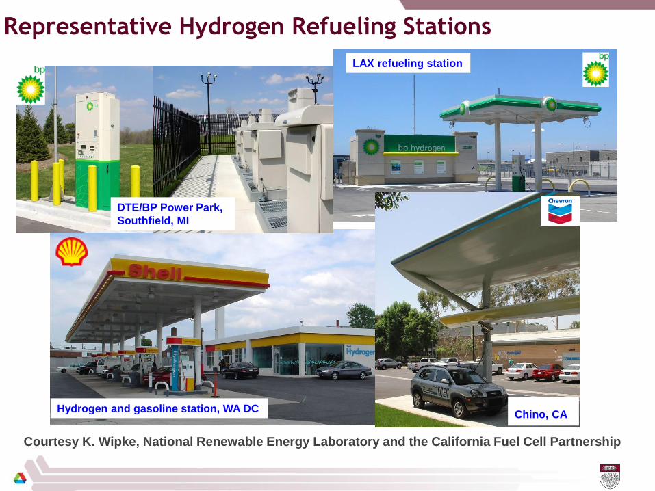
Representative Hydrogen Refueling Stations
28
LAX refueling station
Hydrogen and gasoline station, WA DCChino, CA
DTE/BP Power Park,
Southfield, MI
Courtesy K. Wipke, National Renewable Energy Laboratory and the California Fuel Cell Partnership

29
H2 at Scale – A “Big Idea”

Major Administration Energy Goals
30
1.
2.
3.
4.
5.
H2 at Scale primary impact on 1 and 4 (above), also impacts 2.

Energy System Challenges
31
• Multi-sector requirements
o Transportation
o Industrial
o Grid
• Renewable challenges
o Variable
o Concurrent generation
Over half of U.S. CO2
emissions come from the industrial and
transportation sectors
-5,000
0
5,000
10,000
15,000
20,000
25,000
30,000
35,000
PV Penetration and Hour
Ge
ne
rati
on
(M
W)
PV
Gas
TurbinePumped
StorageHydro
Combined
CycleImports
Coal
Nuclear
Wind
Geo
Exports
Base 2% 6% 10%
(no PV)
Denholm et al. 2008

Carbon-free Electricity Prices Continually Drop with
Increase in Capacity
32
2
4
6
8
10
12
2008 2010 2012 2014 ‘15
$.02/kWh
Contract
Price
cents/kWh
Capacity
(GW)
Source
(Arun Majumdar)
1. DOE EERE
Sunshot Q1’15
Report
2. DOE EERE
Wind Report,
2015
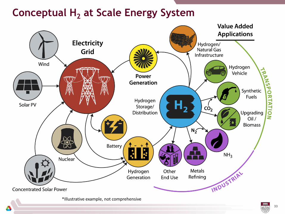
Conceptual H2 at Scale Energy System
33
*Illustrative example, not comprehensive

BAU(Business As Usual) vs. High H2 – CO2 Difference
34
45% reduction in CO2 emissionsGrid 75%, Transportation 25%, Industrial 25%
Emissions difference between 2050 high-H2 and AEO 2040 scenarios (million MT)
Red flows represent a reduction (between scenarios)
H2
11Reduction in Carbon Emissions
-2538
Remaining Carbon
Emissions3237
solar0
nuclear0
hydro0
wind0
geother.1
NG902
coal456
biomass0
Petro.1879
Comm.239
Indus.949
Transp.1226
Resid.263
-1709Elec.550
-327
-405
-97
-96
-405
-97
-231
-462
-1240
1226
949
550

Acknowledgement
35
Fuel Cell Research - Shengqian Ma, Dan Zhao, Shengwen Yuan, Jianglan Shui, Gabriel Goenaga, Chen Chen, Heather Barkholtz, Lina Chong, Lauran Grabstanowicz, Alex Mason, Brianna Reprogle, Sean Comment, Zachary Kaiser, Junbing Yang, Debbie Myers
Technology & Implementation Analyses - John Kopasz, Tom Benjamin, Nancy Garland
H2 at Scale – Amgad Elgowainy
DOE Program Managers – Nancy Garland, Dimitrios Papageorgopoulos
US DOE, US DOE Office of Fuel Cell Technologies and Office of Science. The use of Advanced Photon Source and Electron Microscopy Center are supported by Office of Science, U. S. Department of Energy under Contract DE–AC02–06CH11357.