
HYDRAULIC GEAR PUMPS AND MOTORS - Universal … · Magnum 4 ID02 D010-001 FEATURES Construction...
60
HYDRAULIC GEAR PUMPS AND MOTORS
Transcript of HYDRAULIC GEAR PUMPS AND MOTORS - Universal … · Magnum 4 ID02 D010-001 FEATURES Construction...

Edition: 02/06.2012MA 02 T A Replaces: MA 01 T A
Headquarters:
CASAPPA S.p.A.Via Balestrieri, 1
43044 Lemignano di Collecchio
Parma (Italy)
Tel. (+39) 0521 30 41 11
Fax (+39) 0521 80 46 00
IP VideoconferencingE-mail: [email protected]
HYDRAULIC GEAR PUMPS AND MOTORS

Magnum
2 ID02 D010-001
INDEX
Section Page
FEATURES ......................................................................................................................... 3
GENERAL DATA .................................................................................................................. 6
PUMP PERFORMANCE CURVES .............................................................................................. 8
MOTOR PERFORMANCE CURVES ............................................................................................ 15
SINGLE UNITS DIMENSIONS .................................................................................................. 22
MULTIPLE PUMPS ............................................................................................................. 25
MULTIPLE PUMPS DIMENSIONS ............................................................................................ 32
VERSIONS (OUTBOARD BEARINGS FOR SHAFTS) . ....................................................................... 42
DRIVE SHAFTS .................................................................................................................. 47
MOUNTING FLANGES .......................................................................................................... 48
PORTS ............................................................................................................................ 51
CHANGING ROTATION .......................................................................................................... 56
INSTRUCTIONS .................................................................................................................. 57
HOW TO ORDER ................................................................................................................. 58
O Modi! cation from former edition.
01/0
7.20
05

Magnum
D010-001 ID02 3
FEATURES
DISPLACEMENTSFrom 1.05 in3/rev (17,28 cm3/rev)To 7.66 in3/rev (125,63 cm3/rev)
PRESSUREMax. continuous 4060 psi (280 bar)Max. intermittent 4350 psi (300 bar)Max. peak 4640 psi (320 bar)
MAX. SPEED3000 min-1
Modular design and versatility are the main features of “MAGNUM” series gear pumps and motors. Mounting flange,body and rear cover can be easily assembled to obtain multiple pumps of same or different groups available in standard version, common inlet or separated stages. Wide selection of drive shafts and mounting flanges in SAE version with the possibility of integrated outboard bearing to suit all the applications with axial and radial load on the drive shaft.Port locations available in side or rear locations, and combination of side and rear locations. The low level of noise emission with the high volumetric and overall efficiencies ensure reliability and long working life in heavy duty applications.
�z Wide range of drive shafts and mounting flanges in SAE version
�z More choices of port locations
�z Integrated outboard bearing for heavy duty applications
�z Multiple units available in standard version, common inlet and separated stages
�z Exceptional working life expectancy
1 Mounting flange2 Thrust plate3 Body4 Rear cover5 Gear6 Seal7 Shaft seal
01/0
7.20
05

Magnum
4 ID02 D010-001
FEATURES
Construction External gear type pumps and motors
Mounting SAE flanges
Line connections Screw and flange
Direction of rotation(looking at the drive shaft)
Anti-clock (S) - clockwise (D) - reversible external drain (R)reversible internal drain (B)
Inlet pressure range for pumps 10 ÷ 44 psi - [0,7 ÷ 3 bar (abs.)]
Max back pressure for single rotation motors
p1 (continuous) max 73 psi (5 bar)
p2 (for 20 s) max 116 psi (8 bar)
p3 (for 8 s) max 218 psi (15 bar)
Max drain line pressure on reversible rotation motors 73 psi (5 bar)
Max back pressure on the series motors 2175 psi (150 bar)
Fluid temperature range See table (1)
FluidMineral oil based hydraulic fluids to ISO/DIN and fire resistant fluids [see table (1)].For other fluids please consult our technical sales department.
Viscosity rangeFrom 60 to 456 SSU [12 to 100 mm2/s (cSt)] recommended
Up to 3410 SSU [750 mm2/s (cSt)] permitted
Filtering requirement See table (2)
Casappa recommends to use its own production filters:
GENERAL NOTESAvailable with different inlet and outlet ports. If you use fire resistant fluids, specify the fluid type when ordering.For more information please consult our technical sales department.
Tab. 1
Type Fluid composition Max pressurepsi - (bar)
Max speedmin-1
Temperature °F - (°C)Seals(�)Min Max
continuousMaxpeak
ISO/DIN Mineral oil based hydraulicfluid to ISO/DIN
Seepage 6
Seepage 6
-13 (-25) 176 (80) 212 (100)N
N - H
-13 (-25) 230 (110) 257 (125) V
HFA Oil emulsion in water 5 ÷ 15% of oil 725 (50) 1500 36 (2) 131 (55) N
HFB Water emulsion in oil40% of water 1740 (120) 1500 36 (2) 140 (60) N
HFC Water - glycol 1450 (100) 1500 -4 (-20) 140 (60) N Bz
HFD Phosphate ester 2175 (150) 1500 14 (-10) 176 (80) V Bz
(�) N= Buna N (standard) - N-H= Buna N and high back pressure shaft seals - V= VitonN Bz= Buna N and Bronze thrust plates - V Bz= Viton and Bronze thrust plates
Tab. 2
Working pressure psi (bar) ∆p < 2030∆p < (140)
2030 < ∆p < 3045(140) < ∆p < (210)
∆p > 3045∆p > (210)
Contamination class NAS 1638 10 9 8
Contamination class ISO 4406:1999 21/19/16 20/18/15 19/17/14
Achieved with filter ß10 (c) ≥ 200 according to ISO 16889 - 10 μm 10 μm
Achieved with filter ß25 (c) ≥ 200 according to ISO 16889 25 μm - -
OO
02/
06.2
012
Rep
lace
s: 0
1/07
.200
5

Magnum
D010-001 ID02 5
FEATURES
DEFINITION OF ROTATION DIRECTION LOOKING AT THE DRIVE SHAFT
PRESSURE DEFINITION
p1 Max. continuous pressurep2 Max. intermittent pressurep3 Max. peak pressure
Anti-clock rotation Clockwise rotation Reversible rotation
01/0
7.20
05

Magnum
6 ID02 D010-001
Pump type HDPMotor type HDM
DisplacementMax. pressure
Max. speed Min. speedp1 p2 p3
in3/rev (cm3/rev) psi (bar) min -1
HD. 30•17 1.05(17,28)
4060(280)
4350(300)
4640(320) 3000 400
HD. 30•22 1.34(21,99)
4060(280)
4350(300)
4640(320) 3000 400
HD. 30•24 1.47(24,03)
4060(280)
4350(300)
4640(320) 3000 400
HD. 30•27 1.63(26,70)
4060(280)
4350(300)
4640(320) 3000 400
HD. 30•34 2.11(34,56)
3915(270)
4205(290)
4495(310) 3000 400
HD. 30•38 2.40(39,27)
3915(270)
4205(290)
4495(310) 3000 400
HD. 30•43 2.68(43,98)
3770(260)
4060(280)
4350(300) 3000 400
HD. 30•51 3.16(51,83)
3335(230)
3770(260)
4060(280) 2500 300
HD. 30•56 3.45(56,55)
3118(215)
3553(245)
3843(265) 2500 300
HD. 30•61 3.74(61,26)
2900(200)
3335(230)
3625(250) 2000 250
HD. 30•73 4.50(73,82)
2755(190)
3045(210)
3335(230) 1700 250
HD. 30•82 4.98(81,68)
2465(170)
2755(190)
3045(210) 1500 250
HD. 35•40 2.47(40,46)
3915(270)
4060(280)
4495(310) 3000 400
HD. 35•50 3.12(51,10)
3915(270)
4060(280)
4495(310) 3000 400
HD. 35•63 3.90(63,88)
3915(270)
4060(280)
4495(310) 3000 400
HD. 35•71 4.42(72,40)
3625(250)
4060(280)
4350(300) 3000 400
HD. 35•80 4.94(80,91)
3625(250)
4060(280)
4350(300) 3000 400
HD. 35•90 5.59(91,56)
3335(230)
3770(260)
4060(280) 2700 400
HD. 35•100 6.10(100,08)
3045(210)
3480(240)
3770(260) 2700 400
HD. 35•112 6.88(112,85)
2755(190)
3190(220)
3480(240) 2700 400
HD. 35•125 7.66(125,63)
2465(170)
2900(200)
3190(220) 2500 250
GENERAL DATA PUMPS AND MOTORS
The values in the table refer to unidirectional pumps and motors.Reversible pump and motors max pressures are 15% lower than those shown in table.For different working conditions please consult our sales department.
p1= Max. continuous pressure p2= Max. intermittent pressure p3= Max. peak pressure
01/0
7.20
05
Magnum
D010-001 ID02 7
Pumps Motor
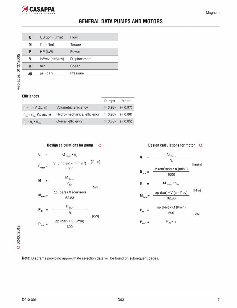
Șv= Șv (V, ∆p, n) Volumetric efficiency (≈ 0,98) (≈ 0,97)
Șhm= Șhm (V, ∆p, n) Hydro-mechanical efficiency (≈ 0,90) (≈ 0,88)
Șt = Șv • Șhm Overall efficiency (≈ 0,88) (≈ 0,85)
Ef! ciences
GENERAL DATA PUMPS AND MOTORS
Q US gpm (l/min) Flow
M lf in (Nm) Torque
P HP (kW) Power
V in3/rev (cm3/rev) Displacement
n min-1 Speed
"p psi (bar) Pressure
Design calculations for pump Design calculations for motor
Q = Q theor. • Șv
[l/min]Qtheor. =
V (cm3/rev) • n (min-1)
1000
M =M theor.
[Nm]Șhm
Mtheor.=∆p (bar) • V (cm3/rev)
62,83
PIN =P OUT
[kW] Șt
POUT =∆p (bar) • Q (l/min)
600
Q =Q theor.
[l/min]Șv
Qtheor. =V (cm3/rev) • n (min-1)
1000
M = M theor. • Șhm
[Nm]Mtheor.=
∆p (bar) • V (cm3/rev)
62,83
PIN =∆p (bar) • Q (l/min)
[kW]600
POUT = PIN • Șt
O 0
2/06
.201
2
O O
Rep
lace
s: 0
1/07
.200
5
Note: Diagrams providing approximate selection data will be found on subsequent pages.

Magnum
8 ID02 D010-001
HDP 30 MAGNUM 30 GEAR PUMPS PERFORMANCE CURVES
HDP 30•17290 psi (20 bar)
4060 psi (280 bar)
HDP 30•22290 psi (20 bar)
4060 psi (280 bar)
HDP 30•27290 psi (20 bar)
4060 psi (280 bar)
HDP 30•34290 psi (20 bar)
3915 psi (270 bar)
HDP 30•43290 psi (20 bar)
3770 psi (260 bar)
HDP 30•51290 psi (20 bar)
3335 psi (230 bar)
HDP 30•61290 psi (20 bar)
2900 psi (200 bar)
HDP 30•73290 psi (20 bar)
2755 psi (190 bar)
HDP 30•82290 psi (20 bar)
2465 psi (170 bar)
HDP 30 Each curve has been obtained at 122 °F (50°C), using oil with viscosity 168 SSU (36 cSt) at 104 °F (40°C) and at these pressures:
HDP 30•24290 psi (20 bar)
4060 psi (280 bar)
HDP 30•38290 psi (20 bar)
3915 psi (270 bar)
HDP 30•56290 psi (20 bar)
3118 psi (215 bar)
O
O 0
2/06
.201
2R
epla
ces:
01/
07.2
005
O New displacements

Magnum
D010-001 ID02 9
HDP 30 MAGNUM 30 GEAR PUMPS PERFORMANCE CURVES
HDP 30•17 HDP 30•22
HDP 30•27HDP 30•24
01/0
7.20
05

Magnum
10 ID02 D010-001
HDP 30 MAGNUM 30 GEAR PUMPS PERFORMANCE CURVES
HDP 30•34 HDP 30•38
HDP 30•43 HDP 30•51
01/0
7.20
05

Magnum
D010-001 ID02 11
HDP 30 MAGNUM 30 GEAR PUMPS PERFORMANCE CURVES
HDP 30•56 HDP 30•61
HDP 30•73 HDP 30•82
01/0
7.20
05

Magnum
12 ID02 D010-001
HDP 35 MAGNUM 35 GEAR PUMPS PERFORMANCE CURVES
HDP 35
HDP 35•40 HDP 35•50
HDP 35•40 290 - 3045 psi (20 - 270 bar)
Each curve has been obtained at 122 °F (50°C), using oil with viscosity 168 SSU (36 cSt) at 104 °F (40°C) and at these pressures:
HDP 35•50290 psi (20 bar)
3915 psi (270 bar)
HDP 35•63290 psi (20 bar)
3915 psi (270 bar)
HDP 35•71290 psi (20 bar)
3625 psi (250 bar)
HDP 35•80290 psi (20 bar)
3625 psi (250 bar)
HDP 35•90290 psi (20 bar)
3335 psi (230 bar)
HDP 35•100290 psi (20 bar)
3045 psi (210 bar)
HDP 35•112290 psi (20 bar)
2755 psi (190 bar)
HDP 35•125290 psi (20 bar)
2465 psi (170 bar)
O
O 0
2/06
.201
2R
epla
ces:
01/
07.2
005
New displacements

Magnum
D010-001 ID02 13
HDP 35 MAGNUM 35 GEAR PUMPS PERFORMANCE CURVES
HDP 35•63 HDP 35•71
HDP 35•80 HDP 35•90
01/0
7.20
05

Magnum
14 ID02 D010-001
HDP 35 MAGNUM 35 GEAR PUMPS PERFORMANCE CURVES
HDP 35•100 HDP 35•112
HDP 35•125
01/0
7.20
05

Magnum
D010-001 ID02 15
HDP 30•17290 psi (20 bar)
4060 psi (280 bar)
HDP 30•22290 psi (20 bar)
4060 psi (280 bar)
HDP 30•27290 psi (20 bar)
4060 psi (280 bar)
HDP 30•34290 psi (20 bar)
3915 psi (270 bar)
HDP 30•43290 psi (20 bar)
3770 psi (260 bar)
HDP 30•51290 psi (20 bar)
3335 psi (230 bar)
HDP 30•61290 psi (20 bar)
2900 psi (200 bar)
HDP 30•73290 psi (20 bar)
2755 psi (190 bar)
HDP 30•82 290 psi (20 bar)2465 psi (170 bar)
HDM 30 MAGNUM 30 GEAR MOTORS PERFORMANCE CURVES
HDM 30 Each curve has been obtained at 122 °F (50°C), using oil with viscosity 168 SSU (36 cSt) at 104 °F (40°C) and at these pressures:
HDP 30•24290 psi (20 bar)
4060 psi (280 bar)
HDP 30•38290 psi (20 bar)
3915 psi (270 bar)
HDP 30•56290 psi (20 bar)
3118 psi (215 bar)
O 0
2/06
.201
2
O
Rep
lace
s: 0
1/07
.200
5
O New displacements

Magnum
16 ID02 D010-001
HDM 30•17 HDM 30•22
HDM 30•24 HDM 30•27
01/0
7.20
05
HDM 30 MAGNUM 30 GEAR MOTORS PERFORMANCE CURVES

Magnum
D010-001 ID02 17
HDM 30•34 HDM 30•38
HDM 30•43 HDM 30•51
01/0
7.20
05HDM 30 MAGNUM 30 GEAR MOTORS PERFORMANCE CURVES

Magnum
18 ID02 D010-001
HDM 30•56 HDM 30•61
HDM 30•73 HDM 30•82
HDM 30 MAGNUM 30 GEAR MOTORS PERFORMANCE CURVES
01/0
7.20
05

Magnum
D010-001 ID02 19
HDM 35
HDM 35•40 HDM 35•50
HDM 35 MAGNUM 35 GEAR MOTORS PERFORMANCE CURVES
HDP 35•50290 psi (20 bar)
3915 psi (270 bar)
HDP 35•63290 psi (20 bar)
3915 psi (270 bar)
HDP 35•71290 psi (20 bar)
3625 psi (250 bar)
HDP 35•80290 psi (20 bar)
3625 psi (250 bar)
HDP 35•90290 psi (20 bar)
3335 psi (230 bar)
HDP 35•100290 psi (20 bar)
3045 psi (210 bar)
HDP 35•112290 psi (20 bar)
2755 psi (190 bar)
HDP 35•125290 psi (20 bar)
2465 psi (170 bar)
Each curve has been obtained at 122 °F (50°C), using oil with viscosity 168 SSU (36 cSt) at 104 °F (40°C) and at these pressures:
HDP 35•40 290 - 3915 psi(20 - 270 bar)
O 0
2/06
.201
2
O
Rep
lace
s: 0
1/07
.200
5
New displacements

Magnum
20 ID02 D010-001
HDM 35•63 HDM 35•71
HDM 35•90HDM 35•80
01/0
7.20
05
HDM 35 MAGNUM 35 GEAR MOTORS PERFORMANCE CURVES

Magnum
D010-001 ID02 21
HDM 35•100 HDM 35•112
HDM 35•125
01/0
7.20
05HDM 35 MAGNUM 35 GEAR MOTORS PERFORMANCE CURVES

Magnum
22 ID02 D010-001
SINGLE UNITS SIDE PORTS L
Pump typeMotor type
A B C D E (IN) F (OUT)mm (inch) mm (inch) mm (inch) mm (inch) mm (inch) mm (inch)
HD. 30•17 184,5 (7.2638) 138 (5.4331)
23,45(0.9232)
150(5.9055)
80(3.1496)
75(2.9528)
HD. 30•22 187,5 (7.3819) 141 (5.5512)
HD. 30•24 188,8 (7.4331) 142,3 (5.6024)
HD. 30•27 190,5 (7.5000) 144 (5.6693)
HD. 30•34 195,5 (7.6969) 149 (5.8661)
HD. 30•38 198,5 (7.8150) 152 (5.9843)
HD. 30•43 201,5 (7.9331) 155 (6.1024)
HD. 30•51 206,5 (8.1299) 160 (6.2992)
HD. 30•56 209,5 (8.2480) 163 (6.4173)
HD. 30•61 212,5 (8.3661) 166 (6.5354)
HD. 30•73 220,5 (8.6811) 174 (6.8504)
HD. 30•82 225,5 (8.8780) 179 (7.0472)
HD. 35•40 224,5 (8.8386) 172 (6.7717)
27,35(1.0768)
172(6.7717)
90(3.5433)
85(3.3465)
HD. 35•50 229,5 (9.0354) 177 (6.9685)
HD. 35•63 235,5 (9.2717) 183 (7.2047)
HD. 35•71 239,5 (9.4291) 187 (7.3622)
HD. 35•80 243,5 (9.5866) 191 (7.5197)
HD. 35•90 248,5 (9.7835) 196 (7.7165)
HD. 35•100 252,5 (9.9409) 200 (7.8740)
HD. 35•112 258,5 (10.1772) 206 (8.1102)
HD. 35•125 264,5 (10.4134) 212 (8.3465)
DRIVE SHAFTS:see page 47
MOUNTING FLANGE:see page 48 ÷ 50
PORTS:see page 51
Tightening torqueNm (lbf in)
V
280 ±28 (2230 ÷ 2726)
The drawing shows a single unit with left rotation.
01/0
7.20
05

Magnum
D010-001 ID02 23
SINGLE UNITS REAR PORTS P
DRIVE SHAFTS:see page 47
MOUNTING FLANGE:see page 48 ÷ 50
PORTS:see page 51
Tightening torqueNm (lbf in)
V
280 ±28 (2230 ÷ 2726)
The drawing shows a single unit with left rotation.
Pump typeMotor type
A B C D E F Gmm (inch) mm (inch) mm (inch) mm (inch) mm (inch) mm (inch) mm (inch)
HD. 30•17 184,5 (7.2638) 173 (6.8110)
23,45(0.9232)
150(5.9055)
80(3.1496)
75(2.9528)
75(2.9528)
HD. 30•22 187,5 (7.3819) 176 (6.9291)
HD. 30•24 188,8 (7.4331) 177,3 (6.9803)
HD. 30•27 190,5 (7.5000) 179 (7.0472)
HD. 30•34 195,5 (7.6969) 184 (7.2441)
HD. 30•38 198,5 (7.8150) 187 (7.3622)
HD. 30•43 201,5 (7.9331) 190 (7.4803)
HD. 30•51 206,5 (8.1299) 195 (7.6772)
HD. 30•56 209,5 (8.2480) 198 (7.7953)
HD. 30•61 212,5 (8.3661) 201 (7.9134)
HD. 30•73 220,5 (8.6811) 209 (8.2283)
HD. 30•82 225,5 (8.8780) 214 (8.4252)
HD. 35•40 224,5 (8.8386) 213 (8.3858)
27,35(1.0768)
172(6.7717)
90(3.5433)
85(3.3465)
89(3.5039)
HD. 35•50 229,5 (9.0354) 218 (8.5827)
HD. 35•63 235,5 (9.2717) 224 (8.8189)
HD. 35•71 239,5 (9.4291) 228 (8.9764)
HD. 35•80 243,5 (9.5866) 232 (9.1339)
HD. 35•90 248,5 (9.7835) 237 (9.3307)
HD. 35•100 252,5 (9.9409) 241 (9.4882)
HD. 35•112 258,5 (10.1772) 247 (9.7244)
HD. 35•125 264,5 (10.4134) 253 (9.9606)
01/0
7.20
05

Magnum
24 ID02 D010-001
Pump typeA Ports code (ODT)
mm (inch) IN OUT
HDP 35•40 213 (8.3858)
OH(1 7/8” - 12 UNF - 2B)
OG(1 5/8” - 12 UNF - 2B)
HDP 35•50 218 (8.5827)
HDP 35•63 224 (8.8190)
HDP 35•71 228 (8.9764)
HDP 35•80 232 (9.1339)
DRIVE SHAFTS:see page 47
MOUNTING FLANGE:see page 48 ÷ 50
PORTS:see page 55
Tightening torqueNm (lbf in)
V
280 ±28 (2230 ÷ 2726)
The drawing shows a single unit with left rotation.
MAGNUM 35 SINGLE PUMPS WITH LARGER REAR PORTS P
01/0
7.20
05

Magnum
D010-001 ID02 25
MULTIPLE PUMPS
MAGNUM series pumps can be coupled together in combination. Where input power requirement of each element varies, that with the greater requirement must be at the drive shaft end, and progressively smaller to the rear.Features and performances are the same as the corresponding single pumps, but pressures must be limited by the transmissible torque of the drive and connecting shafts. To have appropriate data, use the formula below.
The maximum rotational speed is that of the lowest rated speed of the single units incorporated.
Available with separated inlet, common inlet and separated stages.
Combination MAGNUM + KAPPA 20 series and MAGNUM + POLARIS 20 series are available with standard version and EM version with reduced dimensions for O.E.M.s.
For more information please consult our technical sales department.For KAPPA 20 and POLARIS 20 series general data please consult the proper technical catalogues.
M lbf in (Nm) Torque
V in3/rev (cm3/rev) Displacement
"p psi (bar) Pressure
Șhm= Șhm (V, ∆p, n) (≈ 0,90) Hydro-mechanical efficiency
Note: The torque absorbed from the shaft of the first pump results from the sum of the torques due to all single stages. The achieved value must not exceed the maximum torque limit given for the shaft of the first pump. Diagrams providing approximate selection data will be found on page 26.
M =Mtheor.
[Nm]Șhm
Mtheor.=∆p (bar) • V (cm3/rev)
62,83
O
O 0
2/06
.201
2R
epla
ces:
01/
07.2
005

Magnum
26 ID02 D010-001
ABSORBED TORQUE
HDP 35 (1) HDP 30 (2)
KP 20 - PLP 20 (3)
Let us consider a double pump HDP35•80 + HDP30•27. If we suppose that we have to work with the first pump at a pressure of 2900 psi (200 bar) and the second pump at a pressure of 2175 psi (150 bar), the graph 1 shows that the torque absorbed by HDP35•80 is 2523 lbf in (285 Nm) and the graph 2 shows that the torque absorbed by HDP30•27 is 620 lbf in (70 Nm) acceptable value because it doesn’t exceed the maximum con-necting shaft torque that is 1505 lbf in (170 Nm), see page 27. The torque to be transmitted by the first drive shaft will thus be2523+620= 3143 lbf in (285+70= 355 Nm), this value must not exceed the shaft’s maximum rated value.
DRIVE SHAFT SELECTION
01/0
7.20
05

Magnum
D010-001 ID02 27
MULTIPLE PUMPS HDP.. / HDP..
HDP 35/35 STANDARD VERSION
60 MAX 350 Nm (3098 lbf in) Connecting shaft
HDP 35/30 STANDARD VERSION
HDP 30/30 STANDARD VERSION
Connecting flange
F0
F1
Separated inlet
Common inlet
61 MAX 170 Nm (1505 lbf in) Connecting shaftConnecting flange
G0
G1
Separated inlet
Common inlet
65 MAX 170 Nm (1505 lbf in) Connecting shaftConnecting flange
M0
M1
Separated inlet
Common inlet
REAR COVER CONNECTION
All multiple pumps with more than two sections are available with bracket.
SEPARATED INLET COMMON INLETWithout bracket With bracket Without bracket With bracket
0 9 1 8
01/0
7.20
05

Magnum
28 ID02 D010-001
DOUBLE PUMPS HDP35 / KP20
STANDARD VERSION
98 MAX 110 Nm (974 lbf in) Connecting shaftConnecting flange
H7
Separated inlet
KP20•.... - N6
98 MAX 110 Nm (974 lbf in) Connecting shaftConnecting flange
H7
Common inlet
KP20•.... - N7
EM VERSION
96 MAX 110 Nm (974 lbf in) Connecting shaftConnecting flange
H7
Separated inlet
KP20•.... - N6 / EM
96 MAX 110 Nm (974 lbf in) Connecting shaftConnecting flangeCommon inlet
KP20•.... - N7 / EMH7
98 MAX 110 Nm (974 lbf in) Connecting shaftConnecting flange
W4
Separated stages
KP20•.... - Z6
O 0
2/06
.201
2R
epla
ces:
01/
07.2
005
OO O

Magnum
D010-001 ID02 29
DOUBLE PUMPS HDP35 / PLP20
STANDARD VERSION
98 MAX 110 Nm (974 lbf in) Connecting shaftConnecting flange
H6
Separated inlet
PLP20•.... - H6
98 MAX 110 Nm (974 lbf in) Connecting shaftConnecting flange
H7
Common inlet
PLP20•.... - H7
EM VERSION
96 MAX 110 Nm (974 lbf in) Connecting shaftConnecting flange
H6
Separated inlet
PLP20•.... - H6 / EM
96 MAX 110 Nm (974 lbf in) Connecting shaftConnecting flangeCommon inlet
PLP20•.... - H7 / EMH7
98 MAX 110 Nm (974 lbf in) Connecting shaftConnecting flange
W4
Separated stages
PLP20•.... - Z6
O 0
2/06
.201
2R
epla
ces:
01/
07.2
005
OO O

Magnum
30 ID02 D010-001
DOUBLE PUMPS HDP30 / KP20
STANDARD VERSION
97 MAX 110 Nm (974 lbf in) Connecting shaftConnecting flange
N6
Separated inlet
KP20•.... - N6
97 MAX 110 Nm (974 lbf in) Connecting shaftConnecting flange
N7
Common inlet
KP20•.... - N7
EM VERSION
81 MAX 110 Nm (974 lbf in) Connecting shaftConnecting flange
N6
Separated inlet
KP20•.... - N6 / EM
81 MAX 110 Nm (974 lbf in) Connecting shaftConnecting flangeCommon inlet
KP20•.... - N7 / EMN7
97 MAX 110 Nm (974 lbf in) Connecting shaftConnecting flange
W4
Separated stages
KP20•.... - Z6
O 0
2/06
.201
2R
epla
ces:
01/
07.2
005
OO
O

Magnum
D010-001 ID02 31
DOUBLE PUMPS HDP35 / PLP20
STANDARD VERSION
97 MAX 110 Nm (974 lbf in) Connecting shaftConnecting flange
N6
Separated inlet
PLP20•.... - N6
97 MAX 110 Nm (974 lbf in) Connecting shaftConnecting flange
N7
Common inlet
PLP20•.... - N7
EM VERSION
81 MAX 110 Nm (974 lbf in) Connecting shaftConnecting flange
N6
Separated inlet
PLP20•.... - N6 / EM
81 MAX 110 Nm (974 lbf in) Connecting shaftConnecting flangeCommon inlet
PLP20•.... - N7 / EMN7
97 MAX 110 Nm (974 lbf in) Connecting shaftConnecting flange
W4
Separated stages
PLP20•.... - Z6
O 0
2/06
.201
2R
epla
ces:
01/
07.2
005
OO
O

Magnum
32 ID02 D010-001
MULTIPLE PUMPS SAME GROUPS
Pump typeA B C D E G H I L M (IN) N (OUT)
mm(inch)
mm(inch)
mm(inch)
mm(inch)
mm(inch)
mm(inch)
mm(inch)
mm(inch)
mm(inch)
mm(inch)
mm(inch)
HDP35/35 139+F(5.4724+F)
82+F(3.2283+F)
60,5(2.3819)
27,35(1.0807)
98(3.8583)
82(3.2283)
91,5(3.6024)
172(6.7717)
162,4(6.3937)
90(3.5433)
85(3.3465)
HDP30/30 115+F(4.5276+F)
70+F(2.7559+F)
54,5(2.1457)
23,45(0.9232)
80(3.1496)
70(2.7559)
75,5(2.9724)
150(5.9055)
133,5(5.2559)
80(3.1496)
75(2.9528)
DRIVE SHAFTS:see page 47
MOUNTING FLANGE:see page 48 ÷ 50
PORTS:see page 51
Tightening torqueNm (lbf in)
V
280 ±28 (2230 ÷ 2726)
The drawing shows a pump with left rotation.
Pump typeF
mm (inch)
HDP 35•40 33 (1.2992)
HDP 35•50 38 (1.4961)
HDP 35•63 44 (1.7323)
HDP 35•71 48 (1.8898)
HDP 35•80 52 (2.0472)
HDP 35•90 57 (2.2441)
HDP 35•100 61 (2.4016)
HDP 35•112 67 (2.6378)
HDP 35•125 73 (2.8740)
Pump typeF
mm (inch)
HDP 30•17 23 (0.9055)
HDP 30•22 26 (1.0236)
HDP 30•24 27,3 (1.0748)
HDP 30•27 29 (1.1417)
HDP 30•34 34 (1.3386)
HDP 30•38 37 (1.4567)
HDP 30•43 40 (1.5748)
HD. 30•51 45 (1.7717)
HDP 30•56 48 (1.8898)
HDP 30•61 51 (2.0079)
HDP 30•73 59 (2.3228)
HDP 30•82 64 (2.5197)
01/0
7.20
05

Magnum
D010-001 ID02 33
MULTIPLE PUMPS HDP35 / HDP30
Pump typeA B
mm(inch)
mm(inch)
HDP35/30 139+C(5.4724+C)
76+D(2.9921+D)
DRIVE SHAFTS:see page 47
MOUNTING FLANGE:see page 49 ÷ 50
PORTS:see page 51
Tightening torqueNm (lbf in)
V
280 ±28 (2230 ÷ 2726)
The draw shows a pump with left rotation.
Pump typeC
mm (inch)
HDP 35•40 33 (1.2992)
HDP 35•50 38 (1.4961)
HDP 35•63 44 (1.7323)
HDP 35•71 48 (1.8898)
HDP 35•80 52 (2.0472)
HDP 35•90 57 (2.2441)
HDP 35•100 61 (2.4016)
HDP 35•112 67 (2.6378)
HDP 35•125 73 (2.8740)
Pump typeD
mm (inch)
HDP 30•17 23 (0.9055)
HDP 30•22 26 (1.0236)
HDP 30•24 27,3 (1.0748)
HDP 30•27 29 (1.1417)
HDP 30•34 34 (1.3386)
HDP 30•38 37 (1.4567)
HDP 30•43 40 (1.5748)
HD. 30•51 45 (1.7717)
HDP 30•56 48 (1.8898)
HDP 30•61 51 (2.0079)
HDP 30•73 59 (2.3228)
HDP 30•82 64 (2.5197)
01/0
7.20
05

Magnum
34 ID02 D010-001
DOUBLE PUMPS HDP../ KP20 STANDARD VERSION
SEPARATED INLET
COMMON INLET
SEPARATED STAGES01
/07.
2005

Magnum
D010-001 ID02 35
DOUBLE PUMPS HDP../ KP20 STANDARD VERSION
Pump typeA B F G H (IN) I (OUT) L
mm(inch)
mm(inch)
mm(inch)
mm(inch)
mm(inch)
mm(inch)
mm(inch)
HDP35/KP20 139+E(5.4724+E)
68(2.6772)
27,35(1.0807)
11,27(0.4437)
90(3.5433)
85(3.3465)
172(6.7717)
HDP30/KP20 115+E(4.5276+E)
62(2.4409)
23,45(0.9232)
7,45(0.2933)
80(3.1496)
75(2.9528)
150(5.9055)
Tightening torque Nm (lbf in)
V V1 V2
280 ±28 (2230 ÷ 2726) 25 ±2,5 (199 ÷ 243) 70 ±7 (558 ÷ 682)
Drawings show pumps with left rotation.
DRIVE SHAFTS:see page 47
MOUNTING FLANGE:see page 48 ÷ 50
PORTS:see page 51
Pump typeE
mm (inch)
HDP 35•40 33 (1.2992)
HDP 35•50 38 (1.4961)
HDP 35•63 44 (1.7323)
HDP 35•71 48 (1.8898)
HDP 35•80 52 (2.0472)
HDP 35•90 57 (2.2441)
HDP 35•100 61 (2.4016)
HDP 35•112 67 (2.6378)
HDP 35•125 73 (2.8740)
Pump typeE
mm (inch)
HDP 30•17 23 (0.9055)
HDP 30•22 26 (1.0236)
HDP 30•24 27,3 (1.0748)
HDP 30•27 29 (1.1417)
HDP 30•34 34 (1.3386)
HDP 30•38 37 (1.4567)
HDP 30•43 40 (1.5748)
HD. 30•51 45 (1.7717)
HDP 30•56 48 (1.8898)
HDP 30•61 51 (2.0079)
HDP 30•73 59 (2.3228)
HDP 30•82 64 (2.5197)
Pump typeC D M
mm (inch) mm (inch) mm (inch)
KP 20•4 44,5 (1.7520) 27,5 (1.0827) 61,5 (2.4213)
KP 20•6,3 47 (1.8504) 27,5 (1.0827) 64 (2.5197)
KP 20•8 49,5 (1.9488) 27,5 (1.0827) 66,5 (2.6181)
KP 20•11,2 53 (2.0866) 27,5 (1.0827) 70 (2.7559)
KP 20•14 51,5 (2.0276) 33 (1.2992) 68,5 (2.6969)
KP 20•16 57 (2.2441) 33 (1.2992) 74 (2.9134)
KP 20•20 63,5 (2.5000) 33 (1.2992) 80,5 (3.1693)
KP 20•25 56,5 (2.2244) 48 (1.8898) 73,5 (2.8937)
KP 20•31,5 66,5 (2.6181) 48 (1.8898) 83,5 (3.2874)
01/0
7.20
05

Magnum
36 ID02 D010-001
DOUBLE PUMPS HDP.. / PLP20 STANDARD VERSION
SEPARATED INLET
COMMON INLET
SEPARATED STAGES01
/07.
2005

Magnum
D010-001 ID02 37
DOUBLE PUMPS HDP.. / PLP20 STANDARD VERSION
Pump typeA B F G H (IN) I (OUT) L
mm(inch)
mm(inch)
mm(inch)
mm(inch)
mm(inch)
mm(inch)
mm(inch)
HDP35/PLP20 139+E(5.4724+E)
68(2.6772)
27,35(1.0807)
11,27(0.4437)
90(3.5433)
85(3.3465)
172(6.7717)
HDP30/PLP20 115+E(4.5276+E)
62(2.4409)
23,45(0.9232)
7,45(0.2933)
80(3.1496)
75(2.9528)
150(5.9055)
Tightening torque Nm (lbf in)
V V1 V2
280 ±28 (2230 ÷ 2726) 25 ±2,5 (199 ÷ 243) 70 ±7 (558 ÷ 682)
Drawings show pumps with left rotation.
DRIVE SHAFTS:see page 47
MOUNTING FLANGE:see page 48 ÷ 50
PORTS:see page 51
Pump typeE
mm (inch)
HDP 35•40 33 (1.2992)
HDP 35•50 38 (1.4961)
HDP 35•63 44 (1.7323)
HDP 35•71 48 (1.8898)
HDP 35•80 52 (2.0472)
HDP 35•90 57 (2.2441)
HDP 35•100 61 (2.4016)
HDP 35•112 67 (2.6378)
HDP 35•125 73 (2.8740)
Pump typeE
mm (inch)
HDP 30•17 23 (0.9055)
HDP 30•22 26 (1.0236)
HDP 30•24 27,3 (1.0748)
HDP 30•27 29 (1.1417)
HDP 30•34 34 (1.3386)
HDP 30•38 37 (1.4567)
HDP 30•43 40 (1.5748)
HD. 30•51 45 (1.7717)
HDP 30•56 48 (1.8898)
HDP 30•61 51 (2.0079)
HDP 30•73 59 (2.3228)
HDP 30•82 64 (2.5197)
Pump typeC D M
mm (inch) mm (inch) mm (inch)
PLP 20•4 25,75 (1.0138) 49,25 (1.9390) 42,75 (1.6831)
PLP 20•6,3 27 (1.0630) 50,5 (1.9882) 44 (1.7323)
PLP 20•7,2 27,5 (1.0826) 51 (2.0079) 44,5 (1.7520)
PLP 20•8 28,25 (1.1122) 51,75 (2.0374) 45,25 (1.7815)
PLP 20•9 28,9 (1.1378) 52,4 (2.0630) 45,9 (1.8071)
PLP 20•10,5 30,25 (1.1909) 53,75 (2.1161) 47,25 (1.8602)
PLP 20•11,2 30,5 (1.2008) 54 (2.1260) 47,5 (1.8701)
PLP 20•14 33 (1.2992) 56,5 (2.2244) 50 (1.9685)
PLP 20•16 34,75 (1.3681) 58,25 (2.2933) 51,75 (2.0374)
PLP 20•19 36,45 (1.4350) 59,95 (2.3602) 53,45 (2.1043)
PLP 20•20 38 (1.4961) 61,5 (2.4213) 55 (2.1654)
PLP 20•24,5 40,8 (1.6063) 64,3 (2.5315) 57,8 (2.2756)
PLP 20•25 42 (1.6535) 65,5 (2.5787) 59 (2.3228)
PLP 20•27,5 43,35 (1.7067) 66,85 (2.6319) 60,35 (2.3760)
PLP 20•31,5 47 (1.8504) 70,5 (2.7756) 64 (2.5197)
01/0
7.20
05

Magnum
38 ID02 D010-001
DOUBLE PUMPS HDP35 / KP20 EM VERSION
SEPARATED INLET
COMMON INLET
Drawings show pumps with left rotation.Tightening torque Nm (lbf in)
V V1
280 ±28 (2230 ÷ 2726) 70 ±7 (558 ÷ 682)
DRIVE SHAFTS:see page 47
MOUNTING FLANGE:see page 49 ÷ 50
PORTS:see page 51
Pump typeA
mm (inch)
HDP 35•40 172 (6.7717)
HDP 35•50 177 (6.9685)
HDP 35•63 183 (7.2047)
HDP 35•71 187 (7.3622)
HDP 35•80 191 (7.5197)
HDP 35•90 196 (7.7165)
HDP 35•100 200 (7.8740)
HDP 35•112 206 (8.1102)
HDP 35•125 212 (8.3465)
Pump typeB C
mm (inch) mm (inch)
KP 20•4 44,5 (1.7520) 27,5 (1.0827)
KP 20•6,3 47 (1.8504) 27,5 (1.0827)
KP 20•8 49,5 (1.9488) 27,5 (1.0827)
KP 20•11,2 53 (2.0866) 27,5 (1.0827)
KP 20•14 51,5 (2.0276) 33 (1.2992)
KP 20•16 57 (2.2441) 33 (1.2992)
KP 20•20 63,5 (2.5000) 33 (1.2992)
KP 20•25 56,5 (2.2244) 48 (1.8898)
KP 20•31,5 66,5 (2.6181) 48 (1.8898)
01/0
7.20
05

Magnum
D010-001 ID02 39
DOUBLE PUMPS HDP35 / PL20 EM VERSION
SEPARATED INLET
COMMON INLET
Drawings show pumps with left rotation.
Tightening torque Nm (lbf in)
V V1
280 ±28 (2230 ÷ 2726) 70 ±7 (558 ÷ 682)
DRIVESHAFTS:see page 47
MOUNTINGFLANGE:see page 49 ÷ 50
PORTS:see page 51
Pump typeA
mm (inch)
HDP 35•40 172 (6.7717)
HDP 35•50 177 (6.9685)
HDP 35•63 183 (7.2047)
HDP 35•71 187 (7.3622)
HDP 35•80 191 (7.5197)
HDP 35•90 196 (7.7165)
HDP 35•100 200 (7.8740)
HDP 35•112 206 (8.1102)
HDP 35•125 212 (8.3465)
Pump typeB C
mm (inch) mm (inch)
PLP 20•4 25,75 (1.0138) 49,25 (1.9390)
PLP 20•6,3 27 (1.0630) 50,5 (1.9882)
PLP 20•7,2 27,5 (1.0826) 51 (2.0079)
PLP 20•8 28,25 (1.1122) 51,75 (2.0374)
PLP 20•9 28,9 (1.1378) 52,4 (2.0630)
PLP 20•10,5 30,25 (1.1909) 53,75 (2.1161)
PLP 20•11,2 30,5 (1.2008) 54 (2.1260)
PLP 20•14 33 (1.2992) 56,5 (2.2244)
PLP 20•16 34,75 (1.3681) 58,25 (2.2933)
PLP 20•19 36,45 (1.4350) 59,95 (2.3602)
PLP 20•20 38 (1.4961) 61,5 (2.4213)
PLP 20•24,5 40,8 (1.6063) 64,3 (2.5315)
PLP 20•25 42 (1.6535) 65,5 (2.5787)
PLP 20•27,5 43,35 (1.7067) 66,85 (2.6319)
PLP 20•31,5 47 (1.8504) 70,5 (2.7756)
01/0
7.20
05

Magnum
40 ID02 D010-001
DOUBLE PUMPS HDP30 / KP20 EM VERSION
SEPARATED INLET
COMMON INLET
Drawings show pumps with left rotation.Tightening torque Nm (lbf in)
V V1
280 ±28 (2230 ÷ 2726) 70 ±7 (558 ÷ 682)Pump type
Amm (inch)
HDP 30•17 138 (5.4331)
HDP 30•22 141 (5.5512)
HDP 30•24 142,3 (5.6024)
HDP 30•27 144 (5.6693)
HDP 30•34 149 (5.8661)
HDP 30•38 152 (5.9843)
HDP 30•43 155 (6.1024)
HD. 30•51 160 (6.2992)
HDP 30•56 163 (6.4173)
HDP 30•61 166 (6.5354)
HDP 30•73 174 (6.8504)
HDP 30•82 179 (7.0472)
Pump typeB C
mm (inch) mm (inch)
KP 20•4 44,5 (1.7520) 27,5 (1.0827)
KP 20•6,3 47 (1.8504) 27,5 (1.0827)
KP 20•8 49,5 (1.9488) 27,5 (1.0827)
KP 20•11,2 53 (2.0866) 27,5 (1.0827)
KP 20•14 51,5 (2.0276) 33 (1.2992)
KP 20•16 57 (2.2441) 33 (1.2992)
KP 20•20 63,5 (2.5000) 33 (1.2992)
KP 20•25 56,5 (2.2244) 48 (1.8898)
KP 20•31,5 66,5 (2.6181) 48 (1.8898)
DRIVESHAFTS:see page 47
MOUNTINGFLANGE:see page 48 ÷ 49
PORTS:see page 51
01/0
7.20
05

Magnum
D010-001 ID02 41
DOUBLE PUMPS HDP30 / PLP20 EM VERSION
SEPARATED INLET
COMMON INLET
Drawings show pumps with left rotation.Tightening torque Nm (lbf in)
V V1
280 ±28 (2230 ÷ 2726) 70 ±7 (558 ÷ 682)
DRIVESHAFTS:see page 47
MOUNTINGFLANGE:see page 48 ÷ 49
PORTS:see page 51
Pump typeA
mm (inch)
HDP 30•17 138 (5.4331)
HDP 30•22 141 (5.5512)
HDP 30•24 142,3 (5.6024)
HDP 30•27 144 (5.6693)
HDP 30•34 149 (5.8661)
HDP 30•38 152 (5.9843)
HDP 30•43 155 (6.1024)
HD. 30•51 160 (6.2992)
HDP 30•56 163 (6.4173)
HDP 30•61 166 (6.5354)
HDP 30•73 174 (6.8504)
HDP 30•82 179 (7.0472)
Pump typeB C
mm (inch) mm (inch)
PLP 20•4 25,75 (1.0138) 49,25 (1.9390)
PLP 20•6,3 27 (1.0630) 50,5 (1.9882)
PLP 20•7,2 27,5 (1.0826) 51 (2.0079)
PLP 20•8 28,25 (1.1122) 51,75 (2.0374)
PLP 20•9 28,9 (1.1378) 52,4 (2.0630)
PLP 20•10,5 30,25 (1.1909) 53,75 (2.1161)
PLP 20•11,2 30,5 (1.2008) 54 (2.1260)
PLP 20•14 33 (1.2992) 56,5 (2.2244)
PLP 20•16 34,75 (1.3681) 58,25 (2.2933)
PLP 20•19 36,45 (1.4350) 59,95 (2.3602)
PLP 20•20 38 (1.4961) 61,5 (2.4213)
PLP 20•24,5 40,8 (1.6063) 64,3 (2.5315)
PLP 20•25 42 (1.6535) 65,5 (2.5787)
PLP 20•27,5 43,35 (1.7067) 66,85 (2.6319)
PLP 20•31,5 47 (1.8504) 70,5 (2.7756)
01/0
7.20
05

Magnum
42 ID02 D010-001
VERSIONS
For each version, the possible combination between drive shafts and mounting flanges are shown on pages 48 ÷ 50.
Version for applications without radial and axial load on the drive shaft.
Version for applications with low radial load and without axial load on the drive shaft.
Special version with independent shaft for applications with low radial load and without axial load on the drive shaft.
For the outboard bearings life expectancy, diagrams providing approximate selection data will be found on subsequent pages. For particular applications please consult our technical sales department.
0 1 2
Max. torque version 2:HD. 30: 170 Nm (1505 lbf in)HD. 35: 350 Nm (3098 lbf in)
Version for applications with radial and axial load on the drive shaft.
Version for applications with radial and axial load on the drive shaft.
Version for applications with radial and axial load on the drive shaft.
3 4 4
Max. torque version 4:HD. 35: 350 Nm (3098 lbf in)
HD.30 HD.35
Max. torque version 4:HD. 30: 170 Nm (1505 lbf in)
Max. torque version 3:HD. 30: 170 Nm (1505 lbf in)HD. 35: 350 Nm (3098 lbf in)
01/0
7.20
05

Magnum
D010-001 ID02 43
VERSION WITH OUTBOARD BEARING MAGNUM 30 3
X = Distance of the radial load result from themounting flange [mm(in)].
Each curve has been obtained at:
Lubricant oil ISO VG 46
Temperature 140 °F (60 °C)
Without or with very low axial load
Fr Radial load 1000 N (225.0 lbf)
X 30 mm (1.1811 in)
Speed 2000 min-1
Rating fatigue life ≈ 1915 h
Example
01/0
7.20
05

Magnum
44 ID02 D010-001
VERSION WITH OUTBOARD BEARINGS MAGNUM 35 3
X = Distance of the radial load result from themounting flange [mm(in)].
Each curve has been obtained at:
Lubricant oil ISO VG 46
Temperature 140 °F (60 °C)
Without or with very low axial load
Fr Radial load 1000 N (225.0 lbf)
X 30 mm (1.1811 in)
Speed 2000 min-1
Rating fatigue life ≈ 5400 h
Example
01/0
7.20
05

Magnum
D010-001 ID02 45
VERSION WITH OUTBOARD BEARINGS MAGNUM 30 4
X = Distance of the radial load result from themounting flange [mm(in)].
Each curve has been obtained at:
Lubricant oil ISO VG 46
Temperature 140 °F (60 °C)
Without or with very low axial load
Fr Radial load 1500 N (337.5 lbf)
X 30 mm (1.1811 in)
Speed 2000 min-1
Rating fatigue life ≈ 2613 h
Example
01/0
7.20
05

Magnum
46 ID02 D010-001
VERSION WITH OUTBOARD BEARINGS MAGNUM 35 4
X = Distance of the radial load result from themounting flange [mm(in)].
Each curve has been obtained at:
Lubricant oil ISO VG 46
Temperature 140 °F (60 °C)
Without or with very low axial load
Fr Radial load 1500 N (337.5 lbf)
X 30 mm (1.1811 in)
Speed 2000 min-1
Rating fatigue life ≈ 2943 h
Example
01/0
7.20
05

Magnum
D010-001 ID02 47
DRIVE SHAFTS
SAE “BB” STRAIGHT 33Mounting face refer to flange code S3
SAE “B” SPLINE 04Mounting face refer to flange code S3
SAE “C” SPLINE 06Mounting face refer to flange code S8
SAE “C” STRAIGHT 34Mounting face refer to flange code S8
SAE “B” STRAIGHT 32Mounting face refer to flange code S3
SAE “BB” SPLINE 05Mounting face refer to flange code S3
HD. 30 MAX 330 Nm (2921 lbf in) �
HD. 35 MAX 300 Nm (2655 lbf in) �
MAX 200 Nm (1770 lbf in) �
HD. 30 MAX 500 Nm (4426 lbf in) �
HD. 35 MAX 450 Nm (3983 lbf in) �
MAX 280 Nm (2478 lbf in) �
HD. 30 MAX 170 Nm (1505 lbf in) �
HD. 35 MAX 900 Nm (7966 lbf in) �
MAX 600 Nm (5311 lbf in) �
� For “2”, “3” and “4” version whichever end shaft, the max torque applicable is:HD. 30 MAX 170 Nm (1505 lbf in) - HD. 35 MAX 350 Nm (3098 lbf in)
01/0
7.20
05

Magnum
48 ID02 D010-001
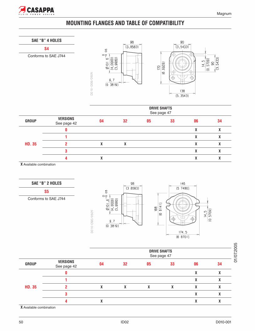
MOUNTING FLANGES AND TABLE OF COMPATIBILITY
SAE “A” 2 HOLES
S1
Conforms to SAE J744
DRIVE SHAFTSSee page 47
GROUP VERSIONSSee page 42 04 32 05 33 06 34
HD. 30
0 X X X X
1 X X X X
2 X X X X X XX Available combination
SAE “B” 2-4 HOLES
S3
Conforms to SAE J744
DRIVE SHAFTSSee page 47
GROUP VERSIONSSee page 42 04 32 05 33 06 34
HD. 30
0 X X X X
1 X X X X
2 X X X X X X
3 X X X X X
4 X X X X XX Available combination
01/0
7.20
05

Magnum
D010-001 ID02 49
MOUNTING FLANGES AND TABLE OF COMPATIBILITY
SAE “C” 2-4 HOLES
S8
Conforms to SAE J744
DRIVE SHAFTSSee page 47
GROUP VERSIONSSee page 42 04 32 05 33 06 34
HD. 30
0 X X X X
1 X X X
2 X X X X X X
3 X X X X X
4 X X X X X
HD. 35
0 X X
1 X X
2 X X X X X X
3 X X
4 X X XX Available combination
GROUPA B
mm (inch) mm (inch)
HD. 30 80 (3.1496) 167,9 (6.6102)
HD. 35 90 (3.5433) 182,8 (7.1969)
O
O 0
2/06
.201
2R
epla
ces:
01/
07.2
005
Magnum
50 ID02 D010-001
MOUNTING FLANGES AND TABLE OF COMPATIBILITY
SAE “B” 4 HOLES
S4
Conforms to SAE J744
DRIVE SHAFTSSee page 47
GROUP VERSIONSSee page 42 04 32 05 33 06 34
HD. 35
0 X X
1 X X
2 X X X X
3 X X
4 X X XX Available combination
SAE “B” 2 HOLES
S5
Conforms to SAE J744
DRIVE SHAFTSSee page 47
GROUP VERSIONSSee page 42 04 32 05 33 06 34
HD. 35
0 X X
1 X X
2 X X X X X X
3 X X
4 X X XX Available combination
01/0
7.20
05

Magnum
D010-001 ID02 51
PORTS TYPE
L H K P
(z) Not available for reversible pumps and motors with external drain.
(�) Available only for single pumps with larger ports.
01/0
7.20
05
SIDE PORTS REAR PORTSPORTSTYPE Split SSM Spit SSS Gas BSPP SAE ODT Gas BSPP SAE ODT
Pump type IN OUT IN OUT IN OUT IN OUT IN OUT IN OUT
Motor type OUT IN OUT IN OUT IN OUT IN OUT IN OUT IN
HD. 30•17 MC MB SC SB GF GE OF OD GE GE OD OD
HD. 30•22 MC MB SC SB GF GE OF OD GE GE OD OD
HD. 30•27 MC MB SC SB GF GE OF OD GE GE OD OD
HD. 30•34 MC MB SC SB GF GE OF OD GE GE OD OD
HD. 30•38 MC MB SC SB GF GE OF OD GE GE
HD. 30•43 MD MC SD SC GG GF OG OF GF (z) GE
HD. 30•51 MD MC SD SC GG GF OG OF GF (z) GE
HD. 30•56 MD MC SD SC GG GF OG OF GF (z) GE
HD. 30•61 ME MD SE SD GG GF OG OF GF (z) GE
HD. 30•73 ME MD SE SD GG GF OG OF GF (z) GE
HD. 30•82 ME MD SE SD GG GF OG OF GF (z) GE
HD. 35•40 ME MD SE SD GH GG OG OF GG (z) GF OFOH (�)
ODOG (�)
HD. 35•50 ME MD SE SD GH GG OG OF GG (z) GF OFOH (�)
ODOG (�)
HD. 35•63 ME MD SE SD GH GG OG OF GG (z) GF OFOH (�)
ODOG (�)
HD. 35•71 ME MD SE SD GH GG OG OF GG (z) GF OFOH (�)
ODOG (�)
HD. 35•80 ME MD SE SD GH GG OG OF GG (z) GF OFOH (�)
ODOG (�)
HD. 35•90 MF ME SF SE GL GH OH OG GG (z) GF
HD. 35•100 MF ME SF SE GL GH OH OG GG (z) GF
HD. 35•112 MF ME SF SE GL GH OH OG
HD. 35•125 MF ME SF SE GL GH OH OG

Magnum
52 ID02 D010-001
EXTERNAL DRAIN PORTS HD. 30 E HD. 35
Rear port for reversible pumps and motors with external drain (R).For dimensions see page 54.
BSPP
PORTS FOR MULTIPLE PUMPS
SEPARATED INLET SEPARATED STAGES
Inlet and outlet ports are the same as side ports of single pumps (see page 51).
COMMON INLET
Inlet ports are larger than side inlet ports of single pumps (see table below).Outlet ports are the same as side outlet ports of single pumps (see page 51).
SIDE PORTSPORTSTYPE Split SSM Spit SSS Gas BSPP SAE ODT
Pump type IN IN IN IN
HDP 30 ME SE GG OG
HDP 35 MF SF GL OH
01/0
7.20
05

Magnum
D010-001 ID02 53
PORTS SIZE
Tightening torque for low pressure side port
Tightening torque for high pressure side port [values obtained at 5075 psi (350 bar)]
For reversible rotation, please consult only the tightening torque for high pressure side port
SAE FLANGED PORTS J518 - Standard pressure series 3000 PSI SSMMetric thread ISO 60° conforms to ISO/R 262
SAE FLANGED PORTS J518 - Standard pressure series 3000 PSI SSSAmerican straight thread UNC-UNF 60° conforms to ANSI B 1.1
CODEA B C D
mm(in)
mm(in)
mm(in)
ThreadDepth mm (in)
Nm(lbf in)
Nm(lbf in)
MB 19(0.7480)
47,6(1.8740)
22,2(0.8740)
M 1022 (0.8661)
20 +1
(177 ÷ 186)35 +2,5
(310 ÷ 332)
MC 24,5(0.9646)
52,4(2.0630)
26,2(1.0315)
M 1022 (0.8661)
20 +1
(177 ÷ 186)35 +2,5
(310 ÷ 332)
MD 30,5(1.2008)
58,7(2.3110)
30,2(1.1890)
M 1022 (0.8661)
20 +1
(177 ÷ 186)35 +2,5
(310 ÷ 332)
ME 39,3(1.5472)
69,8(2.7480)
35,7(1.4055)
M 1227 (1.0630)
30 +2,5
(266 ÷ 288)65 +5
(575 ÷ 620)
MF 51(2.0079)
77,8(3.0630)
42,9(1.6890)
M 1227 (1.0630)
30 +2,5
(266 ÷ 288) —
CODEA B C D
mm(in)
mm(in)
mm(in)
ThreadDepth mm (in)
Nm(lbf in)
Nm(lbf in)
SB 19(0.7480)
47,6(1.8740)
22,2(0.8740)
3/8 - 16 UNC-2B22 (0.8661)
20 +1
(177 ÷ 186)30 +2,5
(266 ÷ 288)
SC 24,5(0.9646)
52,4(2.0630)
26,2(1.0315)
3/8 - 16 UNC-2B22 (0.8661)
20 +1
(177 ÷ 186)30 +2,5
(266 ÷ 288)
SD 30,5(1.2008)
58,7(2.3110)
30,2(1.1890)
7/16 - 14 UNC-2B28,5 (1.1220) 25 +1
(221 ÷ 230)55 +5
(487 ÷ 531)7/16 - 14 UNC-2B27 (1.0630) (�)
SE 39,3(1.5472)
69,8(2.7480)
35,7(1.4055)
1/2 - 13 UNC-2B27 (1.0630)
30 +2,5
(266 ÷ 288)70 +5
(620 ÷ 664)
SF 51(2.0079)
77,8(3.0630)
42,9(1.6890)
1/2 - 13 UNC-2B27 (1.0630)
30 +2,5
(266 ÷ 288) —
(�) For MAGNUM 35
01/0
7.20
05
Magnum
54 ID02 D010-001
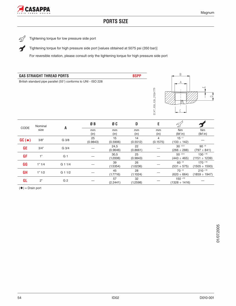
PORTS SIZE
Tightening torque for low pressure side port
Tightening torque for high pressure side port [values obtained at 5075 psi (350 bar)]
For reversible rotation, please consult only the tightening torque for high pressure side port
GAS STRAIGHT THREAD PORTS BSPPBritish standard pipe parallel (55°) conforms to UNI - ISO 228
CODE Nominalsize A
Ø B Ø C D Emm(in)
mm(in)
mm(in)
mm(in)
Nm(lbf in)
Nm(lbf in)
GC (�) 3/8” G 3/8 25(0.9843)
15(0.5906)
14(0.5512)
4(0.1575)
15 +1
(133 ÷ 142) —
GE 3/4” G 3/4 — 24,5(0.9646)
22(0.8661) — 30 +2,5
(266 ÷ 288)90 +5
(797 ÷ 841)
GF 1” G 1 — 30,5(1.2008)
25(0.9843) — 50 +2,5
(443 ÷ 465)130 +10
(1151 ÷ 1239)
GG 1” 1/4 G 1 1/4 — 39(1.5354)
26(1.0236) — 60 +5
(531 ÷ 575)170 +10
(1505 ÷ 1593)
GH 1” 1/2 G 1 1/2 — 45(1.7716)
28(1.1024) — 70 +5
(620 ÷ 664)210 +10
(1859 ÷ 1947)
GL 2” G 2 — 57(2.2441)
32(1.2598) — 150 +10
(1328 ÷ 1416) —
(�) = Drain port
01/0
7.20
05

Magnum
D010-001 ID02 55
PORTS SIZE
SAE STRAIGHT THREAD PORTS J514 ODTAmerican straight thread UNC-UNF 60° conforms to ANSI B 1.1
CODE Nominalsize A
Ø B Ø C D Emm(in)
mm(in)
mm(in)
mm(in)
Nm(lbf in)
Nm(lbf in)
OD 3/4” 1 1/16” - 12 UNF - 2B 42(1.6535)
24,8(0.9764)
20(0.7874)
0,5(0.0197)
40 +2,5
(354 ÷ 376)120 +10
(1062 ÷ 1151)
OF 1” 1 5/16” - 12 UNF - 2B
50(1.9685) 30,5
(1.2008)20
(0.7874)0,5
(0.0197)60 +5
(531 ÷ 575)170 +10
(1505 ÷ 1593)45 (�)(1.7717)
OG 1” 1/4 1 5/8” - 12 UNF - 2B
60(2.3622) 39,1
(1.5394)20
(0.7874)0,5
(0.0197)70 +5
(620 ÷ 664)
—
58 (�)(2.2835)
200 +10
(1770 ÷ 1859)
OH 1” 1/2 1 7/8” - 12 UNF - 2B 65(2.5591)
45,2(1.7795)
20(0.7874)
0,5(0.0197)
100 +5
(885 ÷ 929) —
(�) = For MAGNUM 35
01/0
7.20
05
Tightening torque for low pressure side port
Tightening torque for high pressure side port [values obtained at 5075 psi (350 bar)]
For reversible rotation, please consult only the tightening torque for high pressure side port

Magnum
56 ID02 D010-001
CHANGING ROTATION
Example of changing rotation: from HDP30 pump counterclockwise to clockwise
To change rotation of unidirectional pumps and motors is necessary to operate in the following way:
1. Clean the pump externally with care.
2. Loosen, and remove, the clamp bolts (1).
3. Coat the sharp edges of the drive shaft (4) with adhesive tape and smear a layer of clean grease on the shaft end extension to avoid damaging the lip of the shaft seal when removing the mounting flange.
4. Remove the mounting flange (2), taking care to keep the flange as straight as possible during removal. If the flange is stuck, tap around the edge with a fibre or rubber mallet in order to break away from the body. Ensure that while removing the front mounting flange, the drive shaft and other components remain position.
5. Ease the drive gear (4) up to facilitate removal the front plate (3), taking care that the precision ground surfaces do not become damaged, and remove the drive gear.
6. Remove the driven gear (5) without overturning. The rear plate has not to be removed.
7. Re-locate the driven gear (5) in the position previously occupied by the drive gear (4).
8. Re-locate the drive gear (4) in the position previously occupied by the driven gear (5).
9. Replace the front plate (3) in its original position.
10. Remove the grub screw (6) from the mounting flange (2) and re-locate it in the other threaded hole in the same flange.
11. Gently wipe the machined surface of the mounting flange (2) and the body with a flat hand stone.
12. Refit the front mounting flange (2) turned 180° from its original position.
13. Refit the clamp bolts (1) with the washers and tighten in a crisscross pattern to a torque value of 2230 ÷ 2726 lbf in (280±28 Nm).
14. Check that the pump rotates freely when the drive shaft (4) is turned by hand. If not a pressure plate seal may be pinched.
15. The pump is ready for installation with the original rotation reversed.
01/0
7.20
05

Magnum
D010-001 ID02 57
INSTRUCTIONS
INSTALLATIONPump
The direction of rotation of single-rotation pumps must be the same as that of the drive shaft. Check that the coupling flange correctly aligns the transmission shaft and the pump shaft. Flexible couplings should be used (never rigid fittings) which will not generate an axial or radial load on the pump shaft.
MotorThe direction of rotation of single-rotation motors must match circuit connections. Check that the coupling flange correctly aligns the transmission shaft and the motor shaft. Flexible couplings should be used (never rigid fittings) which will not generate an axial or radial load on the motor shaft.
TANKTank capacity must be sufficient for the system’s operating conditions ( ~ 3 times the amount of oil in circulation) to avoid overheating of the fluid. A heat exchanger should be installed if necessary. The intake and return lines in the tank must be spaced apart (by inserting a vertical divider) to prevent the return-line oil from being taken up again immediately.
LINESThe lines must have a major diameter which is at least as large as the diameter of pump or motor ports, and must be perfectly sealed. To reduce loss of power, the lines should be as short as possible, reducing the sources of hydraulic resistance (elbow, throttling, gate valves, etc.) to a minimum. A length of flexible tubing is recommended to reduce the transmission of vibrations. All return lines must end below the minimum oil level, to prevent foaming. Before connecting the lines, remove any plugs and make sure that the lines are perfectly clean.
FILTERSWe recommend filtering the entire system flow. Filters on suction and return line must be fitted in according to the contamination class as indicated in the first pages of the catalogue. Casappa recommends to use its own production filters:
HYDRAULIC FLUIDUse hydraulic fluid conforming to viscosity data as specified in the first pages of the catalogue. Avoid using mixtures of different oils which could result in decomposition and reduction of the oil’s lubricating power.
STARTING UPCheck that all circuit connections are tight and that the entire system is completely clean. Insert the oil in the tank, using a filter. Bleed the circuit to assist in filling. Set the pressure relief valves to the lowest possible setting. Turn on the system for a few moments at minimum speed, then bleed the circuit again and check the level of oil in the tank. In the difference between pump or motor temperature and fluid temperature exceeds 50°F (10 °C), rapidly switch the system on and off to heat it up gradually. Then gradually increase the pressure and speed of rotation until the pre-set operating levels as specified in the catalogue are attained.
PERIODICAL CHECKS - MAINTENANCEKeep the outside surface clean especially in the area of the drive shaft seal. In fact, abrasive powder can accelerate wear on the seal and cause leakage. Replace filters regularly to keep the fluid clean. The oil level must be checked and oil replaced periodically depending on the system’s operating conditions.
01/0
7.20
05
Magnum
58 ID02 D010-001
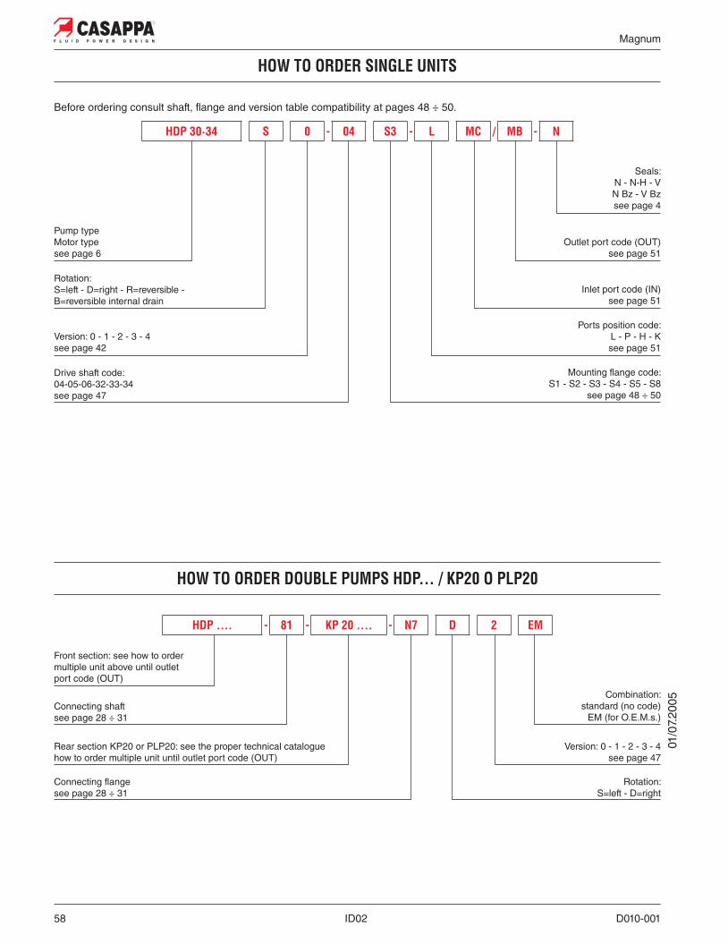
HOW TO ORDER SINGLE UNITS
Before ordering consult shaft, flange and version table compatibility at pages 48 ÷ 50.
Pump typeMotor typesee page 6
Rotation:S=left - D=right - R=reversible - B=reversible internal drain
Version: 0 - 1 - 2 - 3 - 4see page 42
Drive shaft code:04-05-06-32-33-34see page 47
Seals:N - N-H - VN Bz - V Bzsee page 4
Outlet port code (OUT)see page 51
Inlet port code (IN)see page 51
Ports position code:L - P - H - Ksee page 51
Mounting flange code:S1 - S2 - S3 - S4 - S5 - S8
see page 48 ÷ 50
HDP 30·34 S 0 - 04 S3 - L MC / MB - N
HOW TO ORDER DOUBLE PUMPS HDP... / KP20 O PLP20
Front section: see how to ordermultiple unit above until outletport code (OUT)
Connecting shaftsee page 28 ÷ 31
Rear section KP20 or PLP20: see the proper technical cataloguehow to order multiple unit until outlet port code (OUT)
Connecting flangesee page 28 ÷ 31
Rotation:S=left - D=right
Version: 0 - 1 - 2 - 3 - 4see page 47
Combination: standard (no code)
EM (for O.E.M.s.)
HDP .... - 81 - KP 20 .... - N7 D 2 EM
01/0
7.20
05

Magnum
D010-001 ID02 59
HOW TO ORDER MULTIPLE UNITS HDP... / HDP
Before ordering consult shaft, flange and version table compatibility at pages 48 ÷ 50.
Pump typesee page 6
Rotation:S=left - D=right
Versions: 0 - 1 - 2 - 3 - 4see page 42
Section:A=front
I=intermed.P=rear
Seals:N - N-H - VN Bz - V Bzsee page 4
Rear coversee page 27
Mounting flange code:S1 - S3 - S4 - S5 - S8see page 48 ÷ 50
Ports position code: L - P - H - Ksee page 51
Inlet port code (IN)see page 51
Connecting flange codeof the previous section
see page 27
Connecting flange:see page 27
Connecting shaft:see page 27
Outlet port code (OUT)see page 51
HDP 30·34 S - L SD / SC - 65 / M0 N I
Omit code only if ordering complete multiple assembly
01/0
7.20
05
Drive shaft code:04-05-06-32-33-34see page 47
Triple pump HDP 35 / 30 / 30 with common inlet between front and intermediate section.
HDP 35•71 S0-06 S6-L GL/GG-61 G1-N-A / HDP 30•43 S-L /GF-65 M0-N-I / HDP 30•43 S-L GF/GE-65 M0-N-PFront section Intermediate section Rear section
MULTIPLE PUMPS ORDER EXAMPLE
HOW TO ORDER SEPARATED SECTIONS
HDP 35•71-06 S6-L GL/GG / 30•34-L GF/GE-S
HOW TO ORDER AN ASSEMBLED TRIPLE PUMP
Our policy is one of continuous improvement in product. Specification of items may, therefore, be changed withoutnotice.
HDP 30·34 S - L SC / SD - M 9 N P
HDP 35·80 S 0 - 06 S8 - L SE / SD - 61 / G0 N A

Edition: 02/06.2012MA 02 T A Replaces: MA 01 T A
Headquarters:
CASAPPA S.p.A.Via Balestrieri, 1
43044 Lemignano di Collecchio
Parma (Italy)
Tel. (+39) 0521 30 41 11
Fax (+39) 0521 80 46 00
IP VideoconferencingE-mail: [email protected]
HYDRAULIC GEAR PUMPS AND MOTORS