Hydraulic Products · 2015-11-27 · Hydraulic Products – For Clean and Leak-free Hydraulic...
52
Hydraulic Products – For Clean and Leak-free Hydraulic Systems HYDRAULICS
Transcript of Hydraulic Products · 2015-11-27 · Hydraulic Products – For Clean and Leak-free Hydraulic...

Hydraulic Products– For Clean and Leak-free Hydraulic Systems
Hy
dra
ulic
s

2
The Key to Leadership is our MindsetWe have maintained our roots in the heart of Sweden throughout our expansion to other markets worldwide. Born and developed through Swedish ingenuity, we have a heritage to be proud of. ”Made in Sweden” is, for us, a seal of high industrial quality. Add “by CEJN”, and you get the assurance of quality and superior performance.
Our PrOducTs
Our core products are quick connect couplings and nipples for all types of media, from compressed air to gas, breathing air, fluids and hydraulic oil. Regardless of market segment, you can find our products in such diverse fields as agriculture, automotive, construction, off-shore, medical, marine, transportation, wind power and rescue, just to mention a few industries.
cejn - A GLObAL cOMPAny
Being one step ahead demands being one step closer to the market - a key reason why CEJN has a local presence across the globe. Our local sales offices extend the technical know-how of our hub, offer on-location product support, and on-time deliveries to our customers in all major industrial markets. With over 50 years in business developing, manufacturing and selling products for all types of media to every corner of the world, our products ensure quality and superior performance to guarantee profes-sional use and customer benefit.
Hydraulic Range

3
content
FLAT-FAce QuicK cOnnecT cOuPLinGs PAGe
X-series Introduction ....................................................................................................................6 X65 - Standard range, meeting and exceeding ISO16028 ..............................................7 X64 - Pressure eliminator nipples.................................................................................10 X62 - Dimensional interchange with ISO16028 ...........................................................12 X66 - Acid proof stainless steel version acc. to ISO16028 ............................................13 X-Series - Accessories ..................................................................................................14
screw-TO-cOnnecT cOuPLinGs
TlX introduction ........................................................................................................................15 TlX range ..................................................................................................................16
MuLTi-cOuPLinGs
Multi-X Introduction ..................................................................................................................18 Multi-X Range .............................................................................................................20
PLuG-in FiTTinGs
WEO Plug-In Introduction ..........................................................................................................27 WEO Plug-In Range .....................................................................................................29
cOnVenTiOnAL QuicK cOnnecT cOuPLinGs
Classic and Nordic Range Introduction .......................................................................................37 classic range ..............................................................................................................38 Nordic Range ..............................................................................................................39 Nordic Range - Accessories .........................................................................................40
TesT POinT sysTeMs
Snap-Check and Press-Check Series Introduction........................................................................42 Snap-Check Range ......................................................................................................43 Press-Check Range ......................................................................................................45
Hydraulic Range
Your Hydraulic Partner!We have the experience, the competence, the capacity, the quality and the service. Our high demand on ourselves and on our products speaks for itself. When working with us, you can expect the best from our products and from our staff. Our ambitions demand nothing but the best for our customers!
nOTe! Not all connections/versions in the catalogue are standard stock items at factory. The local CEJN companies may carry different versions as standard stock items. Check with an authorized CEJN distributor for availability and prices. Some part numbers may be subject to minimum order quantities.

4
?
?
buT is iT MucH MOre exPensiVe? - i need TO be cOMPeTiTiVe And MAKe A PrOFiT!
"Yes, in most cases the initial investment to upgrade to a clean and leak-free hydraulic system is a bit more expensive. But the pay-off time is quite short and, on the bottom line, it will improve both your competitiveness and profitability as you will be able to work more effectively, have less down time, a longer life for machinery, quick connect couplings and hoses, less oil consumption etc."
clean and Leak-free Hydraulic systems
- It’s our mission
wHere dOes LeAKAGe Occur And wHere dOes dirT enTer HydrAuLic sysTeMs?
"There are two main sources:Poppet valve-type quick connect couplings
- 5-200 ml (0.17-6.8 oz.) spillage during each disconnection - Cleanliness is difficult to maintain- Dust caps are not used or are used incorrectly
Threaded fittings - Correct torque is difficult to achieve- Vibrations unscrew the fittings"
Hydraulic Range - Clean and Leak-free Hydraulic Systems
5
?
? sHOuLd we rePLAce ALL OF Our screw FiTTinGs wiTH weO PLuG-in FiTTinGs? (OeM)
"As a general rule, CEJN WEO Plug-In fittings are a problem solver, not an overall replacement for screw fittings. Start by using them in applications in which traditional screw fittings have resulted in specific problems such as leakage because of unscrewing, premature hose failures, assembly problems, etc. As you come to see the important benefits of WEO Plug-In fittings, you will no doubt want to replace more screw fittings with them."
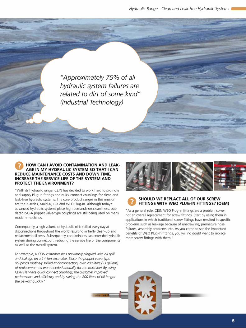
HOw cAn i AVOid cOnTAMinATiOn And LeAK-AGe in My HydrAuLic sysTeM sO THAT i cAn
reduce MAinTenAnce cOsTs And dOwn TiMe, increAse THe serVice LiFe OF THe sysTeM And PrOTecT THe enVirOnMenT?
“With its hydraulic range, CEJN has decided to work hard to promote and supply Plug-In fittings and quick connect couplings for clean and leak-free hydraulic systems. The core product ranges in this mission are the X-series, Multi-X, TLX and WEO Plug-In. Although today’s advanced hydraulic systems place high demands on cleanliness, out-dated ISO-A poppet valve-type couplings are still being used on many modern machines. consequently, a high volume of hydraulic oil is spilled every day at disconnections throughout the world resulting in hefty clean-up and replacement oil costs. Subsequently, contaminants can enter the hydraulic system during connection, reducing the service life of the components as well as the overall system. For example, a CEJN customer was previously plagued with oil spill and leakage on a 14-ton excavator. Since the poppet valve-type couplings routinely spilled at disconnection, over 200 liters (53 gallons) of replacement oil were needed annually for the machine! By using CEJN Flat-Face quick connect couplings, the customer improved performance and efficiency and by saving the 200 liters of oil he got the pay-off quickly.”
Hydraulic Range - Clean and Leak-free Hydraulic Systems
”Approximately 75% of all hydraulic system failures are related to dirt of some kind” (Industrial Technology)

800
700
600
500
400
300
200
100
0
0 0,15 0,3 0,5 0,8 1 1,2 1,4
800
700
600
500
400
300
200
100
0
0 0,15 0,3 0,5 0,8 1 1,2 1,4
?
6
Flat-Face Quick connect couplingsx-series– The high performance ISO16028 flat-face coupling on the market
THe x-series is One OF THe cOre PrOducTs in cejn’s MissiOn TO suPPLy PrOducTs FOr cLeAn And LeAK-Free HydrAuLic sysTeMs
- iT’s An isO FLAT-FAce cOuPLinG, wHAT MAKes cejn beTTer THAn THe OTHer cOuPLinGs AVAiLAbLe On THe MArKeT?
By using our Flat-Face X-series you minimize contamination in your hydraulic system, avoid pollution of the environment as you don’t have spillage at disconnection and at the same time you have a coupling with the highest performance on the market to withstand the toughest applications. By using an eliminator nipple from our X64 series you will also make it possible to connect with high residual pressure in the system.
The CEJN X-series have features that are unique and gives the customer benefits he really can take advantage of.
- The unique design of CEJN’s couplings and nipples makes it possible to connect with some residual pressure without damaging anything in the couplings, also with standard products. This is possible on both couplings and nipples as long as you only have residual pressure on one side. The only limitation to connect is your strength. If your strength is not enough the residual pressure is too high and you need an X64 nipple with pressure eliminator which makes it possible to connect with high residual pressure without excessive force. Residual pressure is something that occurs in more or less all applications where quick connect couplings are used.
- One of the biggest benefits you get by choosing CEJN X-series is longer life time, longer endurance in heavy duty applications and a high working pressure. When producing the CEJN nipples we use case hardening of the nipple bodies which gives the highest surface hardness possible. The most common hardening method is local hardening (induction), on specific areas on the nipple, which typically has a surface hard-ness that is 30% lower than the method CEJN use (see graphics). This is of course a big advantage in the toughest applications but also in more ordinary applications where you will get a longer life time on your quick connect couplings.
surFAce HArdness isO 16028 FLAT-FAce
Har
dnes
s, H
V1
depth from surface, mm
1/2” x65 cejn
1/2” FF competitor 1
1/2” FF competitor 2
Typical results of surface hardness test comparing CEJN with competitors

11.0 7 8654320.5
18.4
183.7
52.8
26.4
15.9
10.6
21.1
264.2
132.1
105.7
79.3
0.26
158.5
23.8
13.2
211.3237.8
1.8
2.6
5.3
1.3
7.9
72.5 101.5
1
10
100
1000
5
20
60
80
400
40
500
200
300
90
70
50
30
600700
800900
4.511.5 2.6 5843.529 11687
165
265
665
565
365
065
765
165 – 1/8”265 – 1/4”365 – 3/8”565 – 1/2”665 – 5/8”765 – 3/4”065 – 1”
7
x65 range - Premium isO 16028 Flat-Face Quick couplingsDN5 (165), DN6.3 (265), DN10 (365), DN 12.5 (565), DN16 (665), DN19 (765), DN25 (065)
dia (mm)*body size
series
Flow rate Max. working pressure Min. burst pressure spillage @
@ ΔP = 3 Bar connected disconnected connected disconnected disconnect
isO - dn inch dash (l/min)** (GPM)** (bar) (Psi) (bar) (Psi) (bar) (Psi) (bar) (Psi) (ml)
12.0 5 1/8" -02 165 7.5 2.0 720 10442 720 10442 1800 26106 1800 261060.02
16.1 6.3 1/4" -04 265 24 6.3 500 7251 500 7251 1500 21755 1500 21755
19.7 10 3/8" -06 365 44 11.6 400 5801 400 5801 1200 17404 1200 17404 0.03
24.5 12.5 1/2" -08 565 93 24.6 400 5801 400 5801 1200 17404 1200 17404 0.04
27.0 16 5/8" -10 665 139 36.7 400 5801 400 5801 1200 17404 1200 17404 0.06
30.0 19 3/4" -12 765 188 49.7 400 5801 400 5801 1200 17404 1200 17404 0.10
36.0 25 1" -16 065 330 87.2 350 5076 350 5076 1200 17404 1200 17404 0.11
• Minimize contamination of your hydraulic system• Spill free disconnection• High performance• Connect under residual pressure, only limited by your strength
Temperature range: ...................................... -30°C – +100°C (-22°F – +212°F) Material seal: ................................................. Nitrile (NBR/PUR, other sealing materials on request)Material: ........................................................ Steel (zinc-nickel, zinc passivation)connectability: .............................................. Only limited by operator strengthdisconnection under pressure: .................... Not allowedinterchangeable with: .................................. All brands dimensionally interchanging with ISO16028
Pressure drop ΔP (bar) [1 bar = 0.1 MPa]
Pressure drop ΔP (PSI)
Flow
rat
e (l/
min
)
Flow
rat
e (G
PM)
Pressure drOP cHArT
(**) If the application is constantly above this flow rate for the respective coupling size, a larger coupling size should be considered to avoid too high a pressure drop. The couplings can handle a much higher flow rate but there is a risk of heat build-up in the system. In general, surge flows above the normal flow rate are not a problem. (*) Diameter for easy identification of ISO16028 Flat-Face coupling size (see picture).
series
dia (*)
CEJN reserves the right to make changes without further notification. Check with an authorized CEJN distributor for availability and prices. All measure-ments are in mm. Thread connections are listed according to ISO Standards. Other connections on request. Please visit our website, www.cejn.com, for general maintenance tips.
Flat-Face Quick Couplings - X65 Range
QR code for X65 Range

8
body size connection Part no. weight (g) Package Qty.isO - dn inch dash description Type standards coupling/Female nipple/Male coupling nipple
5 1/8" -02 G 1/8" (BSP) Female thread DIN 3852 10 165 1201 10 165 6201 96 42
10
6.3 1/4" -04
Rc 1/4" (BSPT) Female thread ISO 7/1 10 265 1102 10 265 6102 143 80
G 1/4" (BSP) Female thread DIN 3852 10 265 1202 10 265 6202 143 78
1/4" NPT Female thread ANSI B1.20.3 10 265 1402 10 265 6402 144 79
7/16"-20 UNF (1/4" SAE) Female thread SAE J 1926-1 10 265 1602 10 265 6602 148 83
M14x1.5 08L Male thread ISO 8434-1-L 10 265 1554 10 265 6554 147 81
M16x1.5 10L Male thread ISO 8434-1-L 10 265 1555 10 265 6555 149 83
10 3/8" -06
Rc 3/8" (BSPT) Female thread ISO 7/1 10 365 1104 10 365 6104 226 120
Rc 1/2" (BSPT) Female thread ISO 7/1 10 365 1105 10 365 6105 230 122
G 3/8" (BSP) Female thread DIN 3852 10 365 1204 10 365 6204 218 115
G 1/2" (BSP) Female thread DIN 3852 10 365 1205 10 365 6205 230 129
3/8 NPT Female thread ANSI B1.20.3 10 365 1404 10 365 6404 226 117
1/2" NPT Female thread ANSI B1.20.3 10 365 1405 10 365 6405 230 120
9/16"-18 UNF (3/8" SAE) Female thread SAE J 1926-1 10 365 1604 10 365 6604 250 139
3/4"-16 UNF (1/2" SAE) Female thread SAE J 1926-1 10 365 1605 10 365 6605 263 153
11/16"-16 ORFS bulkhead Male thread SAE J 1453 10 365 1757 10 365 6757 307 197
M16x1.5 10L Male thread ISO 8434-1-L 10 365 1552 10 365 6552 234 124
M18x1.5 12L Male thread ISO 8434-1-L 10 365 1554 10 365 6554 235 125
M22x1.5 15L Male thread ISO 8434-1-L 10 365 1555 10 365 6555 242 132
M18x1.5 12LS bulkhead Male thread ISO 8434-1-L 10 365 1557 10 365 6557 284 174
M22x1.5 15LS bulkhead Male thread ISO 8434-1-L 10 365 1558 10 365 6558 329 219
G 3/8" JIS ORB Female thread JIS B2351 10 365 1294 10 365 6293 244 115
G 1/2" JIS ORB Female thread JIS B2351 10 365 1295 10 365 6296 253 144
12.5 1/2" -08
Rc 1/2" (BSPT) Female thread ISO 7/1 10 565 1105 10 565 6105 396 272
G 1/2" (BSP) Female thread DIN 3852 10 565 1205 10 565 6205 386 250
G 3/4" (BSP) Female thread DIN 3852 10 565 1207 10 565 6207 375 238
1/2" NPT Female thread ANSI B1.20.3 10 565 1405 10 565 6405 396 264
3/4"-16 UNF (1/2" SAE) Female thread SAE J 1926-1 10 565 1605 10 565 6605 461 333
7/8" - 14 UNF (5/8" SAE) Female thread SAE J 1926-1 10 565 1606 10 565 6606 469 332
1 1/16"-12 UN (SAE 3/4") Female thread SAE J 1926-1 10 565 1607 10 565 6607 469 270
13/16"-16 ORFS bulkhead Male thread SAE J 1453 10 565 1756 10 565 6756 501 371
1"-14 ORFS bulkhead Male thread SAE J 1453 10 565 1758 10 565 6758 585 451
M18x1.5 12L Male thread ISO 8434-1-L 10 565 1554 10 565 6554 375 244
M22x1.5 15L Male thread ISO 8434-1-L 10 565 1555 10 565 6555 382 252
M18x1.5 12LS bulkhead Male thread ISO 8434-1-L 10 565 1557 10 565 6557 423 293
M22x1.5 15LS bulkhead Male thread ISO 8434-1-L 10 565 1558 10 565 6558 461 332
G 1/2" JIS ORB Female thread JIS B2351 10 565 1295 10 565 6296 410 275
16 5/8" -10
Rc 3/4" (BSPT) Female thread ISO 7/1 10 665 1101 10 665 6101 468 314
G 3/4" (BSP) Female thread DIN 3852 10 665 1201 10 665 6201 465 303
3/4" NPT Female thread ANSI B1.20.3 10 665 1401 10 665 6401 476 312
1 1/16"-12 UN (3/4" SAE) Female thread SAE J 1926-1 10 665 1601 10 665 6601 500 335
M26x1.5 18L Male thread ISO 8434-1-L 10 665 1551 10 665 6551 472 312
1"-14 ORFS bulkhead Male thread SAE J 1453 10 665 1752 10 665 6752 624 464
cOuPLinGs & niPPLes
CEJN reserves the right to make changes without further notification. Check with an authorized CEJN distributor for availability and prices. All measurements are in mm. Thread connections are listed according to ISO Standards. Other connections on request. Please visit our website, www.cejn.com, for general maintenance tips.
Flat-Face Quick Couplings - X65 Range
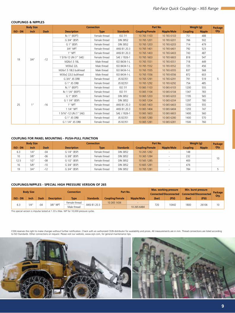
9
body size connection Part no.Max. working pressure Min. burst pressure
Package Qty.
connected/disconnected connected/disconnected
isO - dn inch dash description Type standards coupling/Female nipple/Male (bar) (Psi) (bar) (Psi)
6.3 1/4" -04 3/8" NPTFemale thread
ANSI B1.20.310 265 1434 -
720 10442 1800 26106 10Male thread - 10 265 6484
body size connection Part no. weight (g) Package Qty.isO - dn inch dash description Type standards coupling/Female nipple/Male coupling nipple
19 3/4" -12
Rc 1" (BSPT) Female thread ISO 7/1 10 765 1103 10 765 6103 751 488
5
G 3/4" (BSP) Female thread DIN 3852 10 765 1201 10 765 6201 766 502
G 1" (BSP) Female thread DIN 3852 10 765 1203 10 765 6203 714 479
3/4" NPT Female thread ANSI B1.20.3 10 765 1401 10 765 6401 792 523
1" NPT Female thread ANSI B1.20.3 10 765 1403 10 765 6403 743 487
1 5/16-12 UN (1" SAE) Female thread SAE J 1926-1 10 765 1603 10 765 6603 818 547
M26x1.5 18L Male thread ISO 8434-1-L 10 765 1551 10 765 6551 718 449
M30x2 22L Male thread ISO 8434-1-L 10 765 1552 10 765 6552 725 456
M26x1.5 18LS bulkhead Male thread ISO 8434-1-L 10 765 1555 10 765 6555 837 568
M30x2 22LS bulkhead Male thread ISO 8434-1-L 10 765 1556 10 765 6556 872 603
G 3/4" JIS ORB Female thread JIS B2351 10 765 1291 10 765 6291 791 519
G 1" JIS ORB Female thread JIS B2351 10 765 1292 10 765 6292 754 485
25 1" -16
Rc 1" (BSPT) Female thread ISO 7/1 10 065 1103 10 065 6103 1200 555
Rc 1 1/4" (BSPT) Female thread ISO 7/1 10 065 1104 10 065 6104 1347 783
G 1" (BSP) Female thread DIN 3852 10 065 1203 10 065 6203 1195 565
G 1 1/4" (BSP) Female thread DIN 3852 10 065 1204 10 065 6204 1297 780
1" NPT Female thread ANSI B1.20.3 10 065 1403 10 065 6403 1200 555
1 1/4" NPT Female thread ANSI B1.20.3 10 065 1404 10 065 6404 1293 747
1 5/16"-12 UN (1" SAE) Female thread SAE J 1926-1 10 065 1603 10 065 6603 1400 560
G 1" JIS ORB Female thread JIS B2351 10 065 1280 10 065 6280 1400 570
G 1 1/4" JIS ORB Female thread JIS B2351 10 065 1281 10 065 6281 1500 760
body size connection Part no. weight (g) Package Qty.isO - dn inch dash description Type standards coupling/Female nipple/Male coupling nipple
6.3 1/4" -04 G 1/4" (BSP) Female thread DIN 3852 10 265 1282 - 148
1010 3/8" -06 G 3/8" (BSP) Female thread DIN 3852 10 365 1284 - 232
12.5 1/2" -08 G 1/2" (BSP) Female thread DIN 3852 10 565 1285 - 400
16 5/8" -10 G 3/4" (BSP) Female thread DIN 3852 10 665 1281 - 476
19 3/4" -12 G 3/4" (BSP) Female thread DIN 3852 10 765 1281 - 784 5
cOuPLinG FOr PAneL MOunTinG - PusH-PuLL FuncTiOn
cOuPLinGs/niPPLes - sPeciAL HiGH Pressure VersiOn OF 265
This special version is impulse tested at 1.33 x Max. WP for 10,000 pressure cycles.
cOuPLinGs & niPPLes
CEJN reserves the right to make changes without further notification. Check with an authorized CEJN distributor for availability and prices. All measurements are in mm. Thread connections are listed according to ISO Standards. Other connections on request. Please visit our website, www.cejn.com, for general maintenance tips.
Flat-Face Quick Couplings - X65 Range

265/264 – 1/4”365/364 – 3/8”565/564 – 1/2”665/664 – 5/8”765/764 – 3/4”065/064 – 1”
265/264
365/364
565/564
665/664
765/764
065/064
72.5 101.54.511.5 2.6 5843.529
1
10
100
1000
5
20
60
80
400
40
500
200
300
90
70
50
30
600700
800900
10.1 7 8654320.5
183.7
264.2
132.1
105.7
158.5
211.3237.8
1.8
18.4
2.6
52.8
26.4
15.9
10.6
21.1
5.3
79.3
0.26
1.3
7.9
23.8
13.2
87 116
10
x64 range - isO 16028 Flat-Face Pressure eliminator nipplesDN6.3 (264), DN10 (364), DN12.5 (564), DN16 (664), DN19 (764), DN25 (064)
dia (mm)*body size
series
Flow rate Max. working pressure Min. burst pressure spillage @
@ ΔP = 3 Bar connected disconnected connected disconnected disconnect
isO - dn inch dash (l/min)** (GPM)** (bar) (Psi) (bar) (Psi) (bar) (Psi) (bar) (Psi) (ml)
16.1 6.3 1/4" -04 264 20 5.3 500 7251 500 7251 1500 21755 1500 21755 0.02
19.7 10 3/8" -06 364 44 11.6 400 5801 400 5801 1200 17404 1200 17404 0.03
24.5 12.5 1/2" -08 564 77 20.3 400 5801 400 5801 1200 17404 1200 17404 0.04
27.0 16 5/8" -10 664 116 30.6 400 5801 400 5801 1200 17404 1200 17404 0.06
30.0 19 3/4" -12 764 171 45.2 400 5801 400 5801 1200 17404 1200 17404 0.10
36.0 25 1" -16 064 290 76.6 350 5076 350 5076 1200 17404 1200 17404 0.11
• Connection under high residual pressure• Minimize contamination of your hydraulic system• Spill free disconnection• High performance
Temperature range: ...................................... -30°C – +100°C (-22°F – +212°F) Material seal: ................................................. Nitrile (NBR/PUR)Material: ........................................................ Steel (zinc-nickel, zinc passivation)connectability: .............................................. With static pressure up to 400 bar on the nipple sidedisconnection under pressure: .................... Not allowedinterchangeable with: .................................. All brands dimensionally interchanging with ISO16028
(**) If the application is constantly above this flow rate for the respective coupling size, a larger coupling size should be considered to avoid too high a pressure drop. The couplings can handle a much higher flow rate but there is a risk of heat build-up in the system. In general, surge flows above the normal flow rate are not a problem. (*) Diameter for easy identification of ISO16028 Flat-Face coupling size (see picture).
series
Pressure drop ΔP (bar) [1 bar = 0.1 MPa]
Pressure drop ΔP (PSI)
Flow
rat
e (l/
min
)
Flow
rat
e (G
PM)
Pressure drOP cHArT
dia (*)
CEJN reserves the right to make changes without further notification. Check with an authorized CEJN distributor for availability and prices. All measurements are in mm. Thread connections are listed according to ISO Standards. Other connections on request. Please visit our website, www.cejn.com, for general maintenance tips.
Flat-Face Quick Couplings - X64 Range
QR code for X64 Range

11
body size connection Part no. weight (g) Package Qty.isO - dn inch dash description Type standards nipple/Male nipple
6.3 1/4" -04
Rc 1/4" (BSPT) Female thread ISO 7/1 10 264 6102 144
10
G 1/4" (BSP) Female thread DIN 3852 10 264 6202 140
1/4" NPT Female thread ANSI B1.20.3 10 264 6402 140
7/16"-20 UNF (1/4" SAE) Female thread SAE J 1926-1 10 264 6602 154
M14x1.5 08L Male thread ISO 8434-1-L 10 264 6554 139
M16x1.5 10L Male thread ISO 8434-1-L 10 264 6555 142
10 3/8" -06
Rc 3/8" (BSPT) Female thread ISO 7/1 10 364 6104 182
Rc 1/2" (BSPT) Female thread ISO 7/1 10 364 6105 202
G 3/8" (BSP) Female thread DIN 3852 10 364 6204 174
G 1/2" (BSP) Female thread DIN 3852 10 364 6205 186
3/8" NPT Female thread ANSI B1.20.3 10 364 6404 184
1/2" NPT Female thread ANSI B1.20.3 10 364 6405 203
9/16"-18 UNF (3/8" SAE) Female thread SAE J 1926-1 10 364 6604 196
3/4"-16 UNF (1/2" SAE) Female thread SAE J 1926-1 10 364 6605 207
11/16"-16 ORFS bulkhead Male thread SAE J 1453 10 364 6757 252
M16x1.5 10L Male thread ISO 8434-1-L 10 364 6552 181
M18x1.5 12L Male thread ISO 8434-1-L 10 364 6554 182
M22x1.5 15L Male thread ISO 8434-1-L 10 364 6555 188
M18x1.5 12LS bulkhead Male thread ISO 8434-1-L 10 364 6557 231
M22x1.5 15LS bulkhead Male thread ISO 8434-1-L 10 364 6558 275
G 3/8" JIS ORB Female thread JIS B2351 10 364 6294 200
G 1/2" JIS ORB Female thread JIS B2351 10 364 6295 201
12.5 1/2" -08
Rc 1/2" (BSPT) Female thread ISO 7/1 10 564 6105 368
G 1/2" (BSP) Female thread DIN 3852 10 564 6205 368
G 3/4" (BSP) Female thread DIN 3852 10 564 6207 356
1/2" NPT Female thread ANSI B1.20.3 10 564 6405 373
3/4"-16 UNF (1/2" SAE) Female thread SAE J 1926-1 10 564 6605 388
7/8"-14 UNF (5/8" SAE) Female thread SAE J 1926-1 10 564 6606 373
1 1/16-12 UN (3/4" SAE) Female thread SAE J 1926-1 10 564 6607 427
13/16"-16 ORFS bulkhead Male thread SAE J 1453 10 564 6756 475
1"-14 ORFS bulkhead Male thread SAE J 1453 10 564 6758 557
M18x1.5 12L Male thread ISO 8434-1-L 10 564 6554 349
M22x1.5 15L Male thread ISO 8434-1-L 10 564 6555 356
M18x1.5 12LS bulkhead Male thread ISO 8434-1-L 10 564 6557 398
M22x1.5 15LS bulkhead Male thread ISO 8434-1-L 10 564 6558 437
G 1/2" JIS ORB Female thread JIS B2351 10 564 6295 368
16 5/8" -10
Rc 3/4" (BSPT) Female thread ISO 7/1 10 664 6101 440
G 3/4" (BSP) Female thread DIN 3852 10 664 6201 438
3/4" NPT Female thread ANSI B1.20.3 10 664 6401 444
7/8"-14 UNF (5/8" SAE) Female thread SAE J 1926-1 10 664 6600 477
1 1/16"-12 UN (3/4" SAE) Female thread SAE J 1926-1 10 664 6601 472
M26x1.5 18L Male thread ISO 8434-1-L 10 664 6551 444
1"-14 ORFS bulkhead Male thread SAE J 1453 10 664 6752 597
19 3/4" -12
Rc 1" (BSPT) Female thread ISO 7/1 10 764 6103 682
5
G 3/4" (BSP) Female thread DIN 3852 10 764 6201 732
G 1" (BSP) Female thread DIN 3852 10 764 6203 678
3/4" NPT Female thread ANSI B1.20.3 10 764 6401 754
1" NPT Female thread ANSI B1.20.3 10 764 6403 694
1 1/16"-12 UN (3/4" SAE) Female thread SAE J 1926-1 10 764 6601 678
1 5/16-12 UN (1" SAE) Female thread SAE J 1926-1 10 764 6603 775
M26x1.5 18L Female thread ISO 8434-1-L 10 764 6551 680
M30x2 22L Female thread ISO 8434-1-L 10 764 6552 687
M26x1.5 18LS bulkhead Female thread ISO 8434-1-L 10 764 6555 800
M30x2 22LS bulkhead Male thread ISO 8434-1-L 10 764 6556 835
G 3/4" JIS ORB Female thread JIS B2351 10 764 6291 751
G 1" JIS ORB Female thread JIS B2351 10 764 6292 717
25 1" -16
Rc 1 1/4" (BSPT) Female thread ISO 7/1 10 064 6104 1298
G 1" (BSP) Female thread DIN 3852 10 064 6203 1200
G 1 1/4" (BSP) Female thread DIN 3852 10 064 6204 1271
1 1/4" NPT Female thread ANSI B1.20.3 10 064 6404 1262
1 5/16"-12 UN (1" SAE) Female thread SAE J 1926-1 10 064 6603 1180
G 1" JIS ORB Female thread JIS B2351 10 064 6280 1200
G 1 1/4" JIS ORB Female thread JIS B2351 10 064 6281 1300
niPPLes
Flat-Face Quick Couplings - X64 Range

72.5 101.54.511.5 2.6 5843.529 11687
18.4
183.7
52.8
26.4
15.9
10.6
21.1
5.3
264.2
132.1
105.7
79.3
158.5
7.9
23.8
13.2
211.3237.8
1.8
2.6
1.3
262 – 1/4”362 – 3/8”562 – 1/2”
10.1 7 8654320.5
10
100
1000
5
20
60
80
400
40
500
200
300
90
70
50
30
600700
800900
262
562
362
0.261
12
body size connection Part no. weight (g) Package Qty.isO - dn inch dash description Type standards coupling/Female nipple/Male coupling nipple
6.3 1/4" -04
G 1/4" (BSP) Female thread DIN 3852 10 262 1202 10 262 6202 150 84
10
1/4" NPT Female thread ANSI B1.20.3 10 262 1402 - 150 -
3/8" NPT Female thread ANSI B1.20.3 - 10 262 6404 - 80
10 3/8" -06
G 3/8" (BSP) Female thread DIN 3852 10 362 1204 10 362 6204 224 132
G 1/2" (BSP) Female thread DIN 3852 10 362 1205 10 362 6205 236 128
3/8" NPT Female thread ANSI B1.20.3 10 362 1404 - 232 -
1/2" NPT Female thread ANSI B1.20.3 - 10 362 6405 - 120
12.5 1/2" -08
G 1/2" (BSP) Female thread DIN 3852 10 562 1205 10 562 6205 394 230
G 3/4" (BSP) Female thread DIN 3852 10 562 1207 10 562 6207 372 234
1/2" NPT Female thread ANSI B1.20.3 10 562 1405 - 393 -
3/4" NPT Female thread ANSI B1.20.3 - 10 562 6407 - 226
x62 range - isO 16028 Flat-Face Quick couplings interchangeDN 6.3 (262), DN 10 (362), DN 12.5 (562)
dia (mm)*body size
series
Flow rate Max. working pressure Min. burst pressure spillage @
@ ΔP = 3 Bar connected disconnected connected disconnected disconnect
isO - dn inch dash (l/min)** (GPM)** (bar) (Psi) (bar) (Psi) (bar) (Psi) (bar) (Psi) (ml)
16.1 6.3 1/4" -04 262 19 5.0 250 3630 220 3190 1000 14500 880 12760 0.02
19.7 10 3/8" -06 362 42 11.1 250 3630 220 3190 1000 14500 880 12760 0.03
24.5 12.5 1/2" -08 562 75 19.8 250 3630 220 3190 1000 14500 880 12760 0.04
• Cost-effective design• Minimize contamination of your hydraulic system• Spill free disconnection• For less stringent demands up to 250 bar
Temperature range: ...................................... -30°C – +100°C (-22°F – +212°F) Material seal: ................................................. Nitrile (NBR)Material: ........................................................ Steel (zinc passivation)connectability: .............................................. Without pressuredisconnection under pressure: .................... Not allowedinterchangeable with: .................................. All brands dimensionally interchanging with ISO16028
Pressure drop ΔP (bar) [1 bar = 0.1 MPa]
Pressure drop ΔP (PSI)
Flow
rat
e (l/
min
)
Flow
rat
e (G
PM)
Pressure drOP cHArT (**) If the application is constantly above this flow rate for the respective coupling size, a larger coupling size should be considered to avoid too high a pressure drop. The couplings can handle a much higher flow rate but there is a risk of heat build-up in the system. In general, surge flows above the normal flow rate are not a problem. (*) Diameter for easy identification of ISO16028 Flat-Face coupling size (see picture).
series
cOuPLinGs & niPPLes
dia (*)
CEJN reserves the right to make changes without further notification. Check with an authorized CEJN distributor for availability and prices. All measurements are in mm. Thread connections are listed according to ISO Standards. Other connections on request. Please visit our website, www.cejn.com, for general maintenance tips.
Flat-Face Quick Couplings - X62 Range
QR code for X62 Range

10.1 7 8654320.5
266 – 1/4”366 – 3/8”566 – 1/2”766 – 3/4”
18.4
26.4
15.9
10.6
21.1
0.26
23.8
13.2
1.8
2.6
5.3
1.3
7.9
72.5 101.54.511.5 2.6 5843.529 87
1
10
100
1000
5
20
60
80
400
40
500
200
300
90
70
50
30
600700
800900
183.7
52.8
264.2
132.1
105.7
79.3
158.5
211.3237.8
116
266
566
366
766
13
body size connection Part no. weight (g) Package Qty.isO - dn inch dash description Type standards coupling/Female nipple/Male coupling nipple
6.3 1/4" -04 G 1/4" (BSP) Female thread DIN 3852 10 266 1212 10 266 6212 160 96
10
10 3/8" -06
G 3/8" (BSP) Female thread DIN 3852 10 366 1214 10 366 6214 248 141
G 1/2" (BSP) Female thread DIN 3852 10 366 1215 10 366 6215 263 156
3/8" NPT Female thread ANSI B1.20.3 10 366 1414 10 366 6414 247 139
12.5 1/2" -08
G 1/2" (BSP) Female thread DIN 3852 10 566 1215 10 566 6215 396 268
G 3/4" (BSP) Female thread DIN 3852 10 566 1217 10 566 6217 380 254
1/2" NPT Female thread ANSI B1.20.3 10 566 1415 10 566 6415 415 280
19 3/4" -12G 3/4" (BSP) Female thread DIN 3852 10 766 1211 10 766 6211 748 490
5G 1" (BSP) Female thread DIN 3852 10 766 1213 10 766 6213 748 490
x66 range - isO 16028 Flat-Face stainless steelDN 6.3 (266), DN 10 (366), DN 12.5 (566), DN 19 (766)
dia (mm)*body size
series
Flow rate Max. working pressure *** Min. burst pressure spillage @
@ ΔP = 3 Bar connected disconnected connected disconnected disconnect
isO - dn inch dash (l/min)** (GPM)** (bar) (Psi) (bar) (Psi) (bar) (Psi) (bar) (Psi) (ml)
16.1 6.3 1/4" -04 266 24 6.3 250 3625 250 3625 1000 14503 1000 14503 0.02
19.7 10 3/8" -06 366 44 11.6 250 3625 250 3625 1000 14503 1000 14503 0.03
24.5 12.5 1/2" -08 566 93 24.6 250 3625 250 3625 1000 14503 1000 14503 0.04
30.0 19 3/4" -12 766 188 49.7 250 3625 250 3625 1000 14503 1000 14503 0.10
• All metal components made of AISI 316 stainless steel• Minimize contamination of your hydraulic system• Spill free disconnection• High performance
Pressure drop ΔP (bar) [1 bar = 0.1 MPa]
Pressure drop ΔP (PSI)
Flow
rat
e (l/
min
)
Flow
rat
e (G
PM)
Pressure drOP cHArT (**) If the application is constantly above this flow rate for the respective coupling size, a larger coupling size should be considered to avoid too high a pressure drop. The couplings can handle a much higher flow rate but there is a risk of heat build-up in the system. In general, surge flows above the normal flow rate are not a problem. (*) Diameter for easy identification of ISO16028 Flat-Face coupling size (see picture). (***) In high impulse applications only 50% of max. working pressure is recommended.
series
cOuPLinGs & niPPLes
dia (*)
CEJN reserves the right to make changes without further notification. Check with an authorized CEJN distributor for availability and prices. All measurements are in mm. Thread connections are listed according to ISO Standards. Other connections on request. Please visit our website, www.cejn.com, for general maintenance tips.
Flat-Face Quick Couplings - X66 Range
QR code for X66 Range
Temperature range: ...................................... -20°C – +205°C (-4°F – +401°F) Material seal: ................................................. Viton (FPM), other sealing materials on requestMaterial: ........................................................ Stainless steel, AISI 316connectability: .............................................. Without pressuredisconnection under pressure: .................... Not allowedinterchangeable with: .................................. All brands dimensionally interchanging with ISO16028

14
x-series – Accessories
• Dust caps for couplings and nipples• Seal kits for nipples• Fits all X-Series couplings and nipples
For the X-series we have plastic dust caps, flip dust caps and seal kits available. The dust caps play an important part in prolonging the couplings' life and preventing contamination of your hydraulic system. The seal kits consists of a PUR seal or one O-ring and one backup, depending on the model, for replacement of the front seal in the nipples. The flip dust caps are in general intended for fixed mounted couplings in applications where you want to be sure that the dust cap is on when the coupling is disconnected. Flip dust caps are available in sizes DN10 (3/8") and DN12.5 (1/2").
coupling sizePart no. description
isO - dn inch dash
seal kits for nipples
6.3 1/4" -04
10 265 4900 NBR
10 265 4910 FPM
10 265 4991 PUR
10 3/8" -06
10 365 4900 NBR
10 365 4910 FPM
10 365 4991 PUR
12.5 1/2" -08
10 565 4900 NBR
10 565 4910 FPM
10 565 4991 PUR
16 5/8" -10
10 665 4900 NBR
10 665 4910 FPM
10 665 4991 PUR
19 3/4" -12
10 765 4900 NBR
10 765 4910 FPM
10 765 4991 PUR
25 1" -16 10 065 4900 NBR
dust caps
5 1/8" -0209 165 1000 For couplings
09 165 1050 For nipples
6.3 1/4" -0409 265 1000 For couplings
09 265 1050 For nipples
10 3/8" -0609 365 1000 For couplings
09 365 1050 For nipples
12.5 1/2" -0809 565 1000 For couplings
09 565 1050 For nipples
16 5/8" -1009 665 1000 For couplings
09 665 1050 For nipples
19 3/4" -1209 765 1000 For couplings
09 765 1050 For nipples
25 1" -1609 065 1000 For couplings
09 065 1050 For nipples
Flip dust cap10 3/8" -06 10 365 1010
For couplings12.5 1/2" -08 10 565 1010
CEJN reserves the right to make changes without further notification. Thread connections are listed according to ISO Standards. All measurements are in mm. Check with an authorized CEJN distributor for availability and prices. Please visit our website, www.cejn.com, for general maintenance tips.
X-Series Accessories

15
screw-to-connect couplingsTLx range-The coupling that will stand when the others fall
THe MOsT cOMMOn reAsOn FOr FAiLure OF screw-TO-cOnnecT cOuPLinGs in HeAVy duTy APPLicATiOns is HiGH surGe FLOws
For example, when using a crusher on concrete you will build up high pressure just before you bite through the concrete and, at the moment the crusher bites through the concrete, you will briefly get an extreme surge flow. This surge flow can be several times higher than the ordinary flow rate in the machine and is the cause of many coupling failures. The solution so far has been to use bulky oversized couplings at much higher cost. The new solution is called TLX.
The CEJN TLX has its roots in a patented design with verified performance over many years in industrial auto-couplings which are connected at full working pressure on both sides and used in tough impulse applications. The design of the TLX valve package is highly robust and the seals are protected from being flushed away by surge flow. TLX is designed with a high pitch, high strength round thread profile but without sensitive eliminators or complicated locking systems.
TLx is A FLAT-FAce TwisT LOcK cOuPLinG MAde OF HiGH ALLOy sTeeL And criTicAL cOMPOnenTs Are HArdened FOr MAxiMuM PerFOrMAnce
The surface treatment is Zinc-Nickel which is by far the best surface treatment of steel available. The TLX is a spill free coupling and fully in line with CEJN’s ambition to supply products for clean and leak-free hydraulic systems.
The flow rate of the TLX is not limited to a certain level as it can handle really high flow without failures. The limitation is on the part of the machine as you don’t want to get too high a pressure drop as this will lead to heat build-up in the hydraulic system. If you choose the appropriate size TLX for the flow rate the pump generates, the TLX will also handle the surge flow that can occur in certain applications.

607 – 3/4”
807 – 1 1/4”
707 – 1”
10.1
4.511.5
1
10
100
1000
1.8
18.4
183.7
5
20
60
80
400
40
500
2.6
200
300
52.8
26.4
15.9
10.6
21.1
5.3
264.2
132.1
105.7
79.3
6116.2 87
72.5
5843.529
101.5
7 8654320.50.26
1.3
158.5
7.9
23.8
13.2
211.3237.8
90
70
50
30
600700
800900
807 – 1 1/4” 707 – 1”607 – 3/4”
16
screw-to-connect couplings3/4" (607), 1" (707), 1 1/4" (807)
body sizeFlow rate Max. working pressure Min. burst pressure
ΔP = 3 Bar connected disconnected connected disconnected
inch dash (l/min)** (GPM)** (bar) (Psi) (bar) (Psi) (bar) (Psi) (bar) (Psi)
3/4" -12 169 42.3 400 5800 330 4786 1600 23206 1000 14503
1" -16 291 75.3 400 5800 330 4786 1600 23206 1000 14503
1 1/4" -20 400 105.7 400 5800 330 4786 1600 23206 1000 14503
Temperature range: ...................................... -30°C – +100°C (-22°F – +212°F) Material seal: ................................................. Nitrile (NBR)Material: ........................................................ High alloy steels with Zinc-Nickel surfaceconnectability: .............................................. connection with residual pressure only limited by operator strengthdisconnection under pressure: .................... disconnection with residual pressure in the system is allowed
(**) If the application is constantly above this flow rate for the respective coupling size, a larger coupling size should be considered to avoid too high a pressure drop. The couplings can handle a much higher flow rate but there is a risk of heat build-up in the system. In general, surge flows far above the normal flow rate are not a problem.
series Pressure drop ΔP (bar) [1 bar = 0.1 MPa]
Pressure drop ΔP (PSI)
Flow
rat
e (l/
min
)
Flow
rat
e (G
PM)
Pressure drOP cHArT
• The Super-Duty connector with extremely high resilience to surge flows• The Super-Duty connector that handles the pressure impulses• The Super-Duty connector with pure and simple robustness• Designated for the toughest construction and demolition applications
Screw-to-connect Couplings - TLX Range
QR code for TLX Range

17
coupling size description Part no.
inch dash
3/4" -12
Mounting bracket for TlX
10 607 4960
1" -16 10 707 4970
1 1/4" -16 10 807 4980
coupling sizedescription
Part no.
inch dash coupling/Female nipple/Male
3/4" -12
dust cap
10 607 1000 10 607 1050
1" -16 10 707 1000 10 707 1050
1 1/4" -20 10 807 1000 10 807 1050
coupling size description Part no.
inch dash
3/4" -12
Monkey Wrench 10 807 49991" -16
1 1/4" -20
body size connection Part no.dimension locking
sleeve Hexweight
coupling nipple
inch dash description Type standards coupling/Female nipple/Male (mm) (inch) (kg) (lb) (kg) (lb)
3/4" -12
Rc 3/4" Female thread ISO 7/1 10 607 1101 10 607 6101
55 2.17
1.073 2.4 1.188 2.6
G 3/4" Female threadDIN3852
10 607 1301 10 607 6301 0.989 2.2 1.105 2.4
G 1" Female thread 10 607 1203 10 607 6203 1.029 2.3 1.145 2.5
G 3/4" JIS ORB Female thread JIS B2351 10 607 1231 10 607 6231 1.066 2.4 1.182 2.6
3/4" NPT Female thread ANSI B1.20.3 10 607 1401 10 607 6401 1.079 2.4 1.195 2.6
1 1/16"-12 UN (3/4" SAE) Female thread SAE J 1926-1 10 607 1601 10 607 6601 1.066 2.4 1.182 2.6
1" -16
Rc 1" Female thread ISO 7/1 10 707 1103 10 707 6103
65 2.56
1.892 4.2 2.067 4.6
G 1" Female threadDIN3852
10 707 1203 10 707 6203 1.644 3.6 1.819 4.0
G 1 1/4" Female thread 10 707 1204 10 707 6204 1.788 3.9 1.964 4.3
G 1" JIS ORB Female thread JIS B2351 10 707 1233 10 707 6233 1.891 4.2 2.064 4.6
1" NPT Female thread ANSI B1.20.3 10 707 1403 10 707 6403 1.899 4.2 2.074 4.6
1 5/16"-12 UN (1" SAE) Female thread SAE J 1926-1 10 707 1603 10 707 6603 1.883 4.2 2.059 4.5
1 1/4" -20
Rc 1 1/4" Female thread ISO 7/1 10 807 1104 10 807 6104
75 2.95
3.044 6.7 3.631 8.0
G 1 1/4" Female threadDIN3852
10 807 1204 10 807 6204 2.843 6.3 3.168 7.0
G 1 1/2" Female thread 10 807 1205 10 807 6205 2.959 6.5 3.540 7.8
G 1 1/4" JIS ORB Female thread JIS B2351 10 807 1234 10 807 6234 3.032 6.7 3.649 8.0
1 1/4" NPT Female thread ANSI B1.20.3 10 807 1404 10 807 6404 3.052 6.7 3.640 8.0
1 5/8"-12 UN - (1 1/4" SAE) Female thread SAE J 1926-1 10 807 1604 10 807 6604 3.030 6.7 3.619 8.0
Mounting bracket - Weldable
Monkey wrench - Accessory for simple connection that fits all sizes of TLX
dust caps - Plastic with wire harness
cOuPLinGs & niPPLes
CEJN reserves the right to make changes without further notification. Check with an authorized CEJN distributor for availability and prices. The local CEJN companies may carry different versions as standard stock items. All G-thread connection (BSP) TLX couplings and nipples above are stock standard items at factory. The other thread versions are produced on order and the typical lead time is two weeks from factory. Please visit our website, www.cejn.com, for general maintenance tips.
Screw-to-connect Couplings - TLX Range

18
Multi-couplingsMulti-x range– Advanced technology made easy and user friendly
cLeAn And LeAK-Free MuLTi-cOnnecTiOns in One sTeP wiTH MuLTi-x
CEJN Multi-X is a range of innovative, easy to handle, multi-plates designed to meet and exceed the demands of even the most challenging mobile hydraulic applications. Its innovative design rivals and surpasses other existing multi-plates on the market. The unique design made with the user in mind offers you a plate system that provides great flexibility, high performance, easy installation and trouble-free operation.
Multi-X is fully in line with CEJN’s objective to supply the market with products that result in clean and leak-free hydraulic systems. The WEO Plug-in fitting is a leak-free connection with many other benefits and the spill-free flat-face multi-connection assures prevention of spillage and leakage at the same time as it minimizes the risk of contamination of the hydraulic system. Contamination is one of the most common reasons for failures in hydraulic systems.
Easy tomanEuvEr EnvironmEnt friEndly
flat-facE connEctions
connEctablE undEr rEsidualprEssurE
torsion frEE connEctors
EliminatEs cross connEction
minimizE downtimE during tool changE
flExiblEinstallation
small spacE rEquirEmEnts

19
Multi-Couplings - Multi-X Range
FLexibiLiTy
Multi-X is available in a number of standard configurations, matching the most frequent application needs. The sizes range from DN 10 to DN 19 combined with two, four or six ports in each plate. Each plate can also be equipped with an optional electric connector (available as accessory).
The innovative design allows you to use either part of the plate system mounted as the fixed part without compromising the performance. The mounting bracket is enclosed with the female plate but you can just as easily use it to install the male plate in the application instead.
An extra advantage when you use the male plate as the fixed part is that you can connect standard ISO 16028 Flat-Face couplings to the Multi-X plate, giving you maximum flexibility to use tools and attachments both with and without a Multi-X plate.
The WEO hose connection is self-aligning and makes connection easy and prolongs hose life.
Single ISO 16028 Flat-Face couplings can be used with fixed installed male plates.
Both the female and male plate can be used as the fixed part.
Electric connectors can easily be attached to each plate.
Working pressure of up to 350 bar (5076 PSI) can be used on half the ports simultaneously with the other half of the ports used as return lines with a maximum pressure of 50 bar (725 PSI)
The pressure is punctured without spillage making it simple to connect with residual pressure in the system.
PerFOrMAnce
The Multi-X design allows you to use a working pressure up to 350 bar (5076 PSI) on half the ports simultaneously and the rest of the ports as return lines with a maximum of 50 bar (725 PSI), regardless of whether you use two, four or six ports. The design also offers the possibility to connect the units with residual pressure. (See connectability chart on next page)
cOnnecTiOns
The Multi-X range is outfitted with WEO Plug-In fittings, making them both easy to assemble and to connect. Using Plug-In fittings provides the Multi-X range with the same outstanding features as the CEJN WEO Range products – self-aligning hose connections that prolong hose life, minimize downtimes when the need to replace or remove the hose occurs and its minimal space requirements that allow for more compact designs.
Each Multi-X plate comes with integrated WEO cartridges for easy installation. Use the WEO Hose connection nipples and ferrules to crimp the nipples directly onto the hose or convert your existing hose to WEO Plug-In with the threaded WEO Nipples.
OPerATiOn
Multi-X is easily operated with one hand on the lever and one hand guiding the moving plate during both connection and disconnection. The ergonomic lever placed perpendicular to the hydraulic lines keeps the operator's hands safe. The locking button secures the lever when connected and prevents unintentional disconnection.
All Multi-X male plates are equipped with pressure eliminator nipples to make it possible to connect the plates with residual pressure in the system. By puncturing the pressure, without spillage, it allows for a smooth connection even at a high residual pressure (up to 350 bar) (5076 PSI).
The self-aligning WEO connection removes the torsion in the hose, a common issue when using ordinary fittings, making it easy to align and connect the plates.

L
HH
W
L
3
1
H
H
H
W
3
1
2
HH
W
L
3
1
10.1
4.511.5
1
10
100
1000
1.8
18.4
183.7
DN10 – 3/8”DN12.5 – 1/2”DN19 – 3/4”
DN12.5 - 1/2"
DN10 - 3/8"
DN19 - 3/4"
5
20
60
80
400
40
500
2.6
200
300
52.8
26.4
15.9
10.6
21.1
5.3
264.2
132.1
105.7
79.3
2.6 11687
72.5
5843.529
101.5
7 8654320.50.26
1.3
158.5
7.9
23.8
13.2
211.3237.8
90
70
50
30
600700
800900
20
Multi-x range
series
• Compact design• Great flexibility and high performance• Easy and ergonomic to maneuver - perpendicular lever movement• Connect with residual pressure
Max working pressure:................................. 350 bar (5076 PSI)Min. burst pressure: ...................................... 1200 bar (17405 PSI)Temperature range: ...................................... -30°C – +100°C (-22°F – +212°F) Material female plate: .................................. Zinc plated steel, anodized aluminum, zinc, brassMaterial male plate: ..................................... Zinc plated steel, anodized aluminum, brassMaterial seal: ................................................. NBR/PURdisconnection under pressure: .................... To be avoided. Residual pressure can result in recoil effect during disconnection. Always grip the lever firmly.comment: ...................................................... Contact CEJN representatives for recommendations for high impulse applications.
Pressure drop ΔP (bar) [1 bar = 0.1 MPa]
Flow
rat
e (l/
min
)
Flow
rat
e (G
PM)
FeMALe PLATe
MALe PLATe
connectability case no. DN10 - 3/8” dn12.5 - 1/2” DN19 - 3/4”
1. Connectable with residual pressure on the male side and free to drain on the female side. 350 bar (5076 PSI) 350 bar (5076 PSI) 350 bar (5076 PSI)
2. Connectable with residual pressure on the female side and free to drain on the male side. 250 bar (3626 PSI) 150 bar (2175 PSI) 60 bar (870 PSI)
3. Connectable with residual pressure on the male side and 10 bar return pressure on the female side 250 bar (3626 PSI) 220 bar (3626 PSI) 220 bar (3191 PSI)
Pressure drop ΔP (PSI)Pressure drOP cHArT
Multi-Couplings - Multi-X Range
QR code for Multi-Couplings
CEJN reserves the right to make changes without further notification. Check with an authorized CEJN distributor for availability and prices. All measurements are in mm. Please visit our website, www.cejn.com, for general maintenance tips.

21
coupling size no. of lines
connection Part no. dim. Female plate dim. Male plate
isO - dn inch dash Female plate Male plate Female plate Male plate L w H1 H2 H3 L w H1 H2 H3
10 3/8" -06
2
WEO 1/2" WEO 3/8" 10 932 2000 10 932 2050 83 168 70 138 5 116 116 66 - 5
G 3/8" (BSP) G 3/8" (BSP) 10 932 2200 10 932 2250 83 168 70 138 5 116 116 66 5
12.5 1/2" -08WEO 3/4" WEO 1/2" 10 932 2001 10 932 2051 98 176 79 139 5 138 132 73 - 5
G 1/2" (BSP) G 1/2" (BSP) 10 932 2201 10 932 2251 98 176 79 139 5 138 132 73 5
19 3/4" -12WEO 3/4" WEO 3/4" 10 932 5002 10 932 5052 120 214 107 170 5 182 179 97 - 5
G 3/4" (BSP) G 3/4" (BSP) 10 932 5202 10 932 5252 120 214 107 170 5 182 179 97 5
Multi-x duo
Multi-x Hexa
Multi-x Quattrocoupling size no. of
linesconnection Part no. dim. Female plate dim. Male plate
isO - dn inch dash Female plate Male plate Female plate Male plate L w H1 H2 H3 L w H1 H2 H3
10 3/8" -06 4WEO 1/2" WEO 3/8" 10 932 3000 10 932 3050 83 168 88 155 5 116 116 83 - 5
G 3/8" (BSP) G 3/8" (BSP) 10 932 3200 10 932 3250 83 168 88 155 5 116 116 83 5
10+12.5 3/8"+1/2" -06/-08 2+2WEO 1/2"+3/4" WEO 3/8"+1/2" 10 932 4000 10 932 4050 98 176 99 159 5 138 132 93 - 5
G 3/8"+G 1/2" (BSP) G 3/8"+G 1/2" (BSP) 10 932 4200 10 932 4250 98 176 99 159 5 138 132 93 5
12.5 1/2" -08 4WEO 3/4" WEO 1/2" 10 932 4001 10 932 4051 98 176 99 159 5 138 132 93 - 5
G 1/2" (BSP) G 1/2" (BSP) 10 932 4201 10 932 4251 98 176 99 159 5 138 132 93 5
12.5+19 1/2"+3/4" -08+-12 2+2WEO 3/4" WEO 1/2"+3/4" 10 932 5000 10 932 5050 120 214 107 170 5 182 179 97 - 5
G 1/2"+G 3/4" (BSP) G1/2"+G 3/4" (BSP) 10 932 5200 10 932 5250 120 214 107 170 5 182 179 97 5
coupling size no. of
linesconnection Part no. dim. Female plate dim. Male plate
isO - dn inch dash Female plate Male plate Female plate Male plate L w H1 H2 H3 L w H1 H2 H3
10 3/8" -06 6WEO 1/2" WEO 3/8" 10 932 5006 10 932 5056 120 214 107 170 5 182 179 97 - 5
G 3/8" (BSP) G 3/8" (BSP) 10 932 5206 10 932 5256 120 214 107 170 5 182 179 97 5
CEJN reserves the right to make changes without further notification. Check with an authorized CEJN distributor for availability and prices. All measurements are in mm. Please visit our website, www.cejn.com, for general maintenance tips.
Multi-Couplings - Multi-X Range

22
Multi-x electric connector KitsMulti-X can be fitted with an electric connector kit on both the male and the female plate. The kits contain all necessary components as well as assembly instructions and dust caps.
suitable for Part no. L w H1 H2 H3
Electric connector for female plate Multi-X Duo 10 10 932 0010 83 168 101 169 5
Multi-X Duo 12.5 10 932 0011 98 176 110 170 5
Multi-X Quattro 10 10 932 0012 83 168 119 186 5
Multi-X Quattro 10/12.5Multi-X Quattro 12.5
10 932 0013 98 176 130 190 5
Multi-X Quattro 12.5/19Multi-X Duo 19
10 932 0015 120 214 138 201 5
Multi-X Hexa 10 10 932 0016 83 214 138 201 5
Electric connector for male plate Multi-X Duo 10 10 932 0050 116 116 97 - 5
Multi-X Quattro 10 10 932 0052 116 116 114 - 5
Multi-X Duo 12.5 10 932 0051 138 132 104 - 5
Multi-X Quattro 10/12.5Multi-X Quattro 12.5
10 932 0053 138 132 124 - 5
Multi-X Quattro 12.5/19Multi-X Duo 19
10 932 0055 182 179 128 - 5
Multi-X Hexa 10 10 932 0056 116 179 128 - 5
connections ................................................... 10 + groundVoltage ........................................................... 48 Vcurrent ........................................................... 16 A
suitable for Part no.
Aluminum Cover/Parking Dock for Female Plate Multi-X Duo 10 10 932 1020
Multi-X Duo 12.5 10 932 1021
Multi-X Quattro 10 10 932 1022
Multi-X Quattro 10/12.5Multi-X Quattro 12.5
10 932 1023
Multi-X Quattro 12.5/19Multi-X Duo 19
10 932 1025
Multi-X Hexa 10 10 932 1026
Aluminum Cover/Parking Dock for Male Plate Multi-X Duo 10 10 932 1070
Multi-X Duo 12.5 10 932 1071
Multi-X Quattro 10 10 932 1072
Multi-X Quattro 10/12.5 10 932 1073
Multi-X Quattro 12.5 10 932 1074
Multi-X Quattro 12.5/19Multi-X Duo 19
10 932 1075
Multi-X Hexa 10 10 932 1076
Material ......................................................... aluminum
Multi-x Aluminum cover/Parking dockThe aluminum covers can be used as heavy duty protection when the plates are disconnected. The covers can also easily be mounted and used as fixed parking docks. Covers are only available for plates without electric connectors (can be used with the electric connector but will not cover the electric pins).
CEJN reserves the right to make changes without further notification. Check with an authorized CEJN distributor for availability and prices. All measurements are in mm. Please visit our website, www.cejn.com, for general maintenance tips.
Multi-Couplings - Multi-X Accessories
QR code for Multi-Couplings
Multi-x Accessories

23
Multi-x dust capsThe plastic dust caps are enclosed with each plate, but can also be purchased separately.
suitable for Part no.
dust caps for Female plate Multi-X Duo 10 09 932 1000
Multi-X Quattro 10 09 932 1001
Multi-X Duo 12.5 09 932 1002
Multi-X Quattro 10/12.5Multi-X Quattro 12.5
09 932 1003
Multi-X Quattro 12.5/19Multi-X Duo 19
09 932 1005
Multi-X Hexa 10 09 932 1006
dust caps for Female plate with electric connector Multi-X Duo 10 09 932 1010
Multi-X Duo 12.5 09 932 1012
Multi-X Quattro 10 09 932 1011
Multi-X Quattro 10/12.5Multi-X Quattro 12.5
09 932 1013
Multi-X Quattro 12.5/19Multi-X Duo 19
09 932 1015
Multi-X Hexa 10 09 932 1016
dust caps for Male plateMulti-X Duo 10 09 932 1050
Multi-X Quattro 10 09 932 1051
Multi-X Duo 12.5 09 932 1052
Multi-X Quattro 10/12.5Multi-X Quattro 12.5
09 932 1053
Multi-X Quattro 12.5/19Multi-X Duo 19
09 932 1055
Multi-X Hexa 10 09 932 1056
dust caps for Male plate with electric connectorMulti-X Duo 10 09 932 1060
Multi-X Quattro 10 09 932 1061
Multi-X Duo 12.5 09 932 1062
Multi-X Quattro 10/12.5Multi-X Quattro 12.5
09 932 1063
Multi-X Quattro 12.5/19 09 932 1065
Multi-X Hexa 10 09 932 1066
Material ......................................................... Soft PVC
CEJN reserves the right to make changes without further notification. Check with an authorized CEJN distributor for availability and prices. All measurements are in mm. Please visit our website, www.cejn.com, for general maintenance tips.
Multi-Couplings - Multi-X Spare Parts
QR code for Multi-Couplings
Multi-x spare Parts

24
size dn suitable for Part no. connection
Multi-X Coupling and Nipple kits
Nipple kit
10
Multi-X Duo 10Multi-X Quattro 10Multi-X Quattro 10/12.5Multi-X Hexa 10
10 364 6904 3/8” (DN 10)
12.5
Mutli-X Duo 12.5Multi-X Quattro 12.5Multi-X Quattro 10/12.5Multi-X Quattro 12.5/19
10 564 6905 1/2” (DN 12.5)
19Multi-X Quattro 12.5/19Multi-X Duo 19
10 764 6901 3/4” (DN 19)
coupling kit
10
Multi-X Duo 10Multi-X Quattro 10Multi-X Hexa 10
10 365 1905 1/2” (DN 10)
Multi-X Quattro 10/12.5 10 365 1906 1/2” (DN 10)
12.5
Multi-X Duo 12.5Multi-X Quattro 12.5Multi-X Quattro 10/12.5Multi-X Quattro 12.5/19
10 565 1907 3/4” (DN 12.5)
19 Multi-X Quattro 12.5/19Multi-X Duo 19
10 765 1901 3/4” (DN 19)
seal kits for nipples
Multi-X Seal kits
10 Nipple DN 1010 365 4900 NBR
10 365 4991 PUR
12.5 Nipple DN 12.510 565 4900 NBR
10 565 4991 PUR
19Nipple DN 19
10 765 4900 NBR
10 765 4991 PUR
Multi-x coupling and nipple Kits The couplings and nipples in the Multi-X plates can be replaced. The nipple kit contains nipple and retaining ring. The coupling kit contains a complete set of parts for replacement of one coupling. The seal kits contains one profile ring or an O-ring/backup ring to replace the front seal on the nipple.
Multi-x Mounting bracket The mounting bracket is enclosed with all female Multi-X plates as standard, but can be used with both the female or male plate.
suitable for Part no.
Mounting Bracket for Female/Male Plates Multi-X Duo 10 10 932 4963
Multi-X Quattro 10 10 932 4965
Multi-X Duo 12.5 10 932 4973
Multi-X Quattro 12.5Multi-X Quattro 10/12.5
10 932 4975
Multi-X Quattro 12.5/19Multi-X Duo 19Multi-X Hexa 10
10 932 4985
Mounting Bracket for Female/Male Plates with electrical connector
Multi-X Duo 10 10 932 4964
Multi-X Quattro 10 10 932 4966
Multi-X Duo 12.5 10 932 4974
Multi-X Quattro 12.5Multi-X Quattro 10/12.5
10 932 4976
Multi-X Quattro 12.5/19Multi-X Duo 19Multi-X Hexa 10
10 932 4986
Material ......................................................... Powder coated steel
nbr
Pur
CEJN reserves the right to make changes without further notification. Check with an authorized CEJN distributor for availability and prices. All measurements are in mm. Please visit our website, www.cejn.com, for general maintenance tips.
Multi-Couplings - Multi-X Spare Parts
QR code for Multi-Couplings

25
suitable for Part no.
lever assembly Multi-X Duo 10Multi-X Quattro 10
10 932 4960
Multi-X Duo 12.5Multi-X Quattro 12.5Multi-X Quattro 10/12.5
10 932 4970
Multi-X Quattro 12.5/19Multi-X Duo 10
10 932 4980
Multi-X Hexa 10 10 932 4983
Back lid kit
Multi-X Duo 10Multi-X Quattro 10
10 932 4961
Multi-X Duo 12.5Multi-X Quattro 12.5Multi-X Quattro 10/12.5
10 932 4971
Multi-X Quattro 12.5/19Multi-X Duo 19Multi-X Hexa 10
10 932 4981
center bolt kitMulti-X Duo 10Multi-X Quattro 10
10 932 4962
Multi-X Duo 12.5Multi-X Quattro 12.5Multi-X Quattro 10/12.5
10 932 4972
Multi-X Quattro 12,5/19Multi-X Duo 19
10 932 4982
Multi-X Hexa 10 10 932 4984
locking device
Multi-X Cover/Parking Dock for Male Plate 10 932 4991
lock in house
All Female Multi-X models 10 932 4992
Lock set handle size 1
Multi-X Duo 10 & 12.5Multi-X Quattro 10Multi-X Quattro 10/12.5Multi-X Quattro 12.5
10 932 4993
Lock set handle size 2
Mutli-X Quattro 12.5/19Mutli-X Duo 19Mutli-X Hexa 10
10 932 4994
Multi-x spare Parts
suitable for Part no.
all sizes 10 932 4977
Multi-x slot nut Kit Multi-X Slot Nut Kit can be fitted on both the male and the female plate. For use in high vibration applications where standard nuts are insufficient.
CEJN reserves the right to make changes without further notification. Check with an authorized CEJN distributor for availability and prices. All measurements are in mm. Please visit our website, www.cejn.com, for general maintenance tips.
Multi-Couplings - Multi-X Spare Parts

26
choose connection
Series 727 - WEO-nipples, male JIC-thread 37°
Series 721 - WEO-nipples, female BSP-thread
weO-niPPLes wiTH HydrAuLic HOse cOnnecTiOn
weO-niPPLes wiTH THreAd cOnnecTiOns
Multi-Couplings - Choose connection
CEJN reserves the right to make changes without further notification. Check with an authorized CEJN distributor for availability and prices. All measurements are in mm. Thread connections are listed according to ISO Standards. Please visit our website, www.cejn.com, for general maintenance tips.
Multi-x Part no./description
Multi-x connection
Hoseconnection
straight nippleweOnipple 45°
weOnipple 90°
10 932 2050 10 932 3050
Duo 10, Male plate Quattro 10, Male plate Hexa 10, Male plate
WEO 3/8”DN06 (1/4") 14 710 0604
DN10 (3/8") 14 710 0606 14 712 0606 14 714 0606
10 932 200010 932 205110 932 300010 932 4051
Duo 10, Female plateDuo 12.5, Male plateQuatto 10, Female plateQuattro 12.5, Male plate Hexa 10, Female plate
WEO 1/2”
DN10 (3/8") 14 710 0806 14 714 0806
DN12 (1/2") 14 710 0808 14 712 0808 14 714 0808
10 932 2001 10 932 4001 10 932 500010 932 500210 932 5052
Duo 12.5, Female plateQuattro 12.5, Female plateQuattro 12.5/19, Female plateDuo 19, Female plateDuo 19, Male plate
WEO 3/4”
DN12 (1/2") 14 710 1208
DN20 (3/4") 14 710 1212
10 932 4050 Quattro 10/12.5, Male plate
WEO 3/8”DN06 (1/4") 14 710 0604
DN10 (3/8") 14 710 0606 14 712 0606 14 714 0606
WEO 1/2”DN10 (3/8") 14 710 0806 14 714 0806
DN12 (1/2") 14 710 0808 14 712 0808 14 714 0808
10 932 4000 10 932 5050
Quattro 10/12.5, Female plateQuattro 12.5/19, Male plate
WEO 1/2”DN10 (3/8") 14 710 0806 14 714 0806
DN12 (1/2") 14 710 0808 14 712 0808 14 714 0808
WEO 3/4”DN12 (1/2") 14 710 1208
DN20 (3/4") 14 710 1212
Multi-x Part no./description
Multi-x connection
choose your connection
weO Part no.
10 932 2050 10 932 3050
Duo 10, Male plateQuattro 10, Male plateHexa 10, Male plate
WEO 3/8”
3/8” (BSP) Female 14 721 0606
1/2” (BSP) Female 14 721 0608
9/16”-18 JIC 14 727 0609
3/4”-16 JIC 14 727 0612
10 932 2000 10 932 205110 932 300010 932 4051
Duo 10, Female plateDuo 12.5, Male plate Quatto 10, Female plateQuattro 12.5, Male plateHexa 10, Female plate
WEO 1/2”
3/8” (BSP) Female 14 721 0806
1/2” (BSP) Female 14 721 0848
9/16”-18 JIC 14 727 0809
3/4”-16 JIC 14 727 0812
10 932 2001 10 932 400110 932 500010 932 500210 932 5052
Duo 12.5, Female plateQuattro 12.5, Female plateQuattro 12.5/19, Female plateDuo 19, Female plateDuo 19, Male plate
WEO 3/4”
1/2” (BSP) Female 14 721 1208
3/4” (BSP) Female 14 721 1212
1 1/16”-12 JIC 14 727 1217
10 932 4050 Quattro 10/12.5, Male plate
WEO 3/8”
3/8” (BSP) Female 14 721 0606
1/2” (BSP) Female 14 721 0608
9/16”-18 JIC 14 727 0609
3/4”-16 JIC 14 727 0612
WEO 1/2”
3/8” (BSP) Female 14 721 0806
1/2” (BSP) Female 14 721 0848
9/16”-18 JIC 14 727 0809
3/4”-16 JIC 14 727 0812
10 932 400010 932 5050
Quattro 10/12.5, Female plateQuattro 12.5/19, Male plate
WEO 1/2”
3/8” (BSP) Female 14 721 0806
1/2” (BSP) Female 14 721 0848
9/16”-18 JIC 14 727 0809
3/4”-16 JIC 14 727 0812
WEO 3/4”
1/2” (BSP) Female 14 721 1208
3/4” (BSP) Female 14 721 1212
1 1/16”-12 JIC 14 727 1217
QR code for Multi-Couplings

27
Plug-in FittingsweO Plug-in Fittings- A smart Plug-In solution with extensive cost savings for everyone
nO MATTer wHere in THe cHAin, weO wiLL siMPLy MAKe yOur LiFe eAsier
WEO offers the possibility of more compact designs, shorter maintenance times and minimizes the risk of work related injuries. It all adds up to extensive cost savings and benefits for everyone - the designer, manufacturer and end-user.
At the drawing board: Through its minimal space requirements designers have the possibility to design new compact systems. How? Since our fittings are simply plugged in, you don’t have to worry about hand-tool clearance. Traditional screw to connect fittings require extra space when tightened, but WEO will make it easier for you to build a compact and reliable hydraulic system. With WEO at the drawing board stage, you also cut time on the production line.
On the production line: CEJN WEO Plug-In hose fittings reduce downtime and installation time for equipment manufacturers. The click-to-connect and self-aligning features of the fittings make them easy to install in hydraulic systems, dramatically reducing costs through their quick installation time. Once it has been plugged in, the fitting locks into place, eliminating the need for tightening during follow-up security checks. The tight connection also gives you leak-free connections.
Owner of weO-equipped machine: A machine equipped WEO will save you both time and money. Due to the fact that WEO fittings are self-aligning, twisted hose is no longer a problem giving your hose an extend service life. If necessary, disconnectioncan can be achieved using nothing more than a simple screw driver, it’s as easy as that! When plugged back in, the tight connection ensures leakage is virtually eliminated leaving you with a clog-free system. You can always rest assured the fittings are properly plugged in and don’t have to worry about re-tightening.

28
TecHnicAL dATA
TestsWEO Plug-In hose fittings have been tested and approved by the Swedish Institute of Materials Testing and Research to SS-ISO 8032 – Half Omega Test, and have been burst tested to a minimum pressure of four times the working pressure. The fittings have also been tested and approved by TÜV, Germany.
working Pressure, safety FactorWEO fitting sizes 1/4 inch through 3/4 inch have a maximum working pressure of 350 bar (5075 PSI). The 1-inch size has a maximum working pressure of 250 bar (3625 PSI). A minimum safety factor of 4:1 between burst pressure and working pressure applies to all sizes.
Note: Working pressure may vary among sizes. Refer to the data for each product range. MATeriAL sPeciFicATiOns
Assembly stop – POM
Backup ring – Hytrel®
Release ring – POM
O-Ring – NBR
Locking hooks – hardened steel (zinc passivation)
Coupling body – hardened steel (zinc passivation)
O-Ring – NBR
Nipple body – hardened steel (zinc passivation)
Material seal .................................................. Nitrile (NBR), other sealing materials on request Temperature range ....................................... -30°C 100°C -22°F212°F

29
Material coupling .......................................... Steel (zinc passivation, Cr6 free passiviation) Max. working pressure................................. 350 bar (5076 PSI)Min. burst pressure ....................................... 1400 bar (20305 PSI)Temperature range ....................................... -30°C – +100°C (-22°F – +212°F)
size Part no. A b c d e F G H j Krec. torque
(nm)
1/4" 14 800 0400 10.03+0.08 12.75+0.1 16.55+0.07 17.0+0.1 M18x1 8.5+1 1.1-0.1 10.65+0.1 14.15+0.2 19.65+0.15 25-35 Nm
3/8" 14 800 0600 13.03+0.08 16.95+0.15 20.55+0.07 21.0+0.1 M22x1 8.7+1 1.15-0.1 11.1+0.1 15.5+0.2 21.95+0.15 30-40 Nm
1/2" 14 800 0800 16.03+0.08 19.95+0.15 23.55+0.07 24.0+0.1 M25x1 8.7+1 1.25-0.1 11.3+0.1 15.7+0.2 22.15+0.15 40-50 Nm
3/4" 14 800 1200 23.03+0.08 27.95+0.15 31.05+0.07 31.5+0.1 M33x1.5 11.5+1 1.7-0.1 16.5+0.1 21.4+0.2 31.35+0.15 70-80 Nm
cartridgeThe Flexible Solution will reduce your costs
• Plug-In Cartridge• Working Pressure up to 350 bar (5075 PSI)• Cut assembly and test times• Make more compact hydraulic components and system designs• Shorten maintenance times and minimize work-related injuries• It all adds up to extensive cost savings for all involved
Plug-In systems for hydraulic hose are fast breaking new grounds and more and more equipment and component manufacturers worldwide are turning to the WEO Plug-In system to cut both assembly times and space requirements, as well as providing their customers with equipment made for easy servicing and minimal downtimes.
WEO Plug-In Cartridge is easily integrated into hydraulic components without interfering with the performance or quality. By using the integrated cartridge you get easy and effective assembly and testing, which will reduce your costs. The innovative cartridge cuts space requirements even more by eliminating the need for adapters or female fittings – just Plug-In!
equipment Manufacturers
Using components with integrated WEO Plug-In cartridges will make your assembly easier and faster. You no longer need to assemble adapters or female fittings before attaching the hose or to re-tighten the hose fittings after assembly, thus also minimizing work-related injures. The WEO Plug-In click-to-connect feature also opens up for more compact system designs. Adding up to extensive cost savings!
component Manufacturers
Integrating the WEO Plug-In Cartridge in your components means selling and delivering cost saving benefits to your customer. With no adapters or female fittings necessary for assembly you’ll also make your own testing procedures quick and easy without compromis-ing quality. Adding up to cost savings and new business opportunities
MATeriAL sPeciFicATiOn
O-ring – NBR
Support ring – Hytrel®
Washer – high-alloy steel (zinc passivation, Cr6 free passiviation)
O-ring – NBR
Locking hooks – hardened steel (zinc passivation, Cr6 free passiviation)
Frontpart – steel (zinc passivation, Cr6 free passiviation) Pre-applied micro-encapsulated thread locker
Dustcap – LDPE
CEJN reserves the right to make changes without further notification. Check with an authorized CEJN distributor for availability and prices. All measurements are in mm. Please visit our website, www.cejn.com, for general maintenance tips.
Plug-In Fittings - Cartridge
QR code for Plug-In Fittings - Cartridge

B
E D A
FC
E D
B
A
C
DE
B
C
A
30
series 710 – Straight, Nipple with Hose Connection
Series 710 features Plug-In nipples with straight hose connections for one/two wire braided hydraulic hose in sizes 1/4" to 1"
Part no. connection Max working pressure A b c d F
Nipple, 1/4"14 710 0403 3/16” (5.25 mm) 350 bar (5076 PSI) 10.0 54.5 19.0 2.8 29.2
14 710 0404 1/4” 6.9 mm) 350 bar (5076 PSI) 10.0 58.0 19.0 4.5 30.0
Nipple, 3/8"
14 710 0604 1/4” (6.9 mm) 350 bar (5076 PSI) 13.0 61.0 22.0 4.5 33.0
14 710 0605 5/16” (8.6 mm) 350 bar (5076 PSI) 13.0 61.0 22.0 5.6 33.0
14 710 0606 3/8” (10.1 mm) 350 bar (5076 PSI) 13.0 63.0 22.0 7.0 33.0
Nipple, 1/2"
14 710 0806 3/8” (10.1 mm) 350 bar (5076 PSI) 16.0 63.0 22.0 7.0 33.0
14 710 0808 1/2” (13.6 mm) 350 bar (5076 PSI) 16.0 64.0 22.0 9.5 33.0
14 710 0810 5/8” (16.8 mm) 350 bar (5076 PSI) 15.9 68.5 22.0 9.5 34.3
Nipple, 3/4"
14 710 1208 1/2” (13.6 mm) 350 bar (5076 PSI) 23.0 73.5 31.0 9.5 42.5
14 710 1210 5/8” (16.8 mm) 350 bar (5076 PSI) 23.0 77.5 31.0 12.0 43.3
14 710 1212 3/4” (20 mm) 350 bar (5076 PSI) 23.0 82.0 31.0 15.0 43.0
Nipple, 1" 14 710 1616 1” (26.2 mm) 250 bar (3625 PSI) 30.0 100.5 38.5 21.0 54.0
series 712 – 45°, Nipple with Hose Connection
Series 712 features Plug-In nipples with 45° hose connections for one/two wire braided hydraulic hose in sizes 1/4" to 3/4"
Part no. connection Max working pressure A b c d
Nipple, 1/4" 14 712 0404 1/4” (6.9 mm) 350 bar (5076 PSI) 10.0 28.0 51.0 4.5
Nipple, 3/8"
14 712 0604 1/4” (6.9 mm) 350 bar (5076 PSI) 13.0 32.0 55.0 4.5
14 712 0605 5/16" (8.6 mm) 350 bar (5076 PSI) 13.0 33.0 54.5 5.6
14 712 0606 3/8” (10.1 mm) 350 bar (5076 PSI) 13.0 33.0 59.0 7.0
Nipple, 1/2"14 712 0806 3/8" (10.1 mm) 350 bar (5076 PSI) 16.0 34.0 60.0 7.0
14 712 0808 1/2” (13.6 mm) 350 bar (5076 PSI) 16.0 36.0 66.0 9.0
Nipple, 3/4"
14 712 1208 3/4" (13.6 mm) 350 bar (5076 PSI) 23.0 44.0 73.0 9.0
14 712 1210 5/8" (16.8 mm) 350 bar (5076 PSI) 23.0 55.0 103.0 13.0
14 712 1212 3/4" (20.0 mm) 350 bar (5076 PSI) 23.0 55.0 103.0 15.0
series 714 – 90°, Nipple with Hose Connection
Series 714 features Plug-In nipples with 90° hose connections for one/two wire braided hydraulic hose in sizes 1/4" to 3/4"
Part no. connection Max working pressure A b c d
Nipple, 1/4" 14 714 0404 1/4” (6.9 mm) 350 bar (5076 PSI) 10.0 51.0 34.0 4.5
Nipple, 3/8"
14 714 0604 1/4" (6.9 mm) 350 bar (5076 PSI) 13.0 56.0 34.0 4.5
14 714 0605 5/16" (8.6 mm) 350 bar (5076 PSI) 13.0 60.0 39.0 5.6
14 714 0606 3/8” (10.1 mm) 350 bar (5076 PSI) 13.0 60.0 39.0 7.0
Nipple, 1/2"
14 714 0805 5/16" (8.6 mm) 350 bar (5076 PSI) 16.0 62.0 39.0 5.6
14 714 0806 3/8” (10.1 mm) 350 bar (5076 PSI) 16.0 61.0 39.0 7.0
14 714 0808 1/2” (13.6 mm) 350 bar (5076 PSI) 16.0 69.0 48.0 9.0
Nipple, 3/4"
14 714 1208 1/2" (13.6 mm) 350 bar (5076 PSI) 23.0 79.0 48.0 9.0
14 714 1210 5/8" (16.8 mm) 350 bar (5076 PSI) 23.0 105.5 75.0 13.0
14 714 1212 3/4" (20.0mm) 350 bar (5076 PSI) 23.0 104.5 75.0 14.5
nipples
Plug-In Fittings - WEO Plug-In Fittings
QR code for WEO Plug-In Fittings
e
e
e
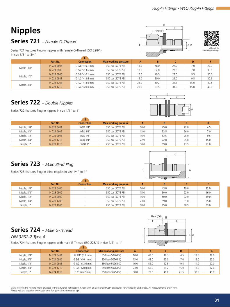
BC
E D A
Hex (F)
D A
CCB
B
E A
C
BHex (G)CF
D AE
31
series 721 – Female G-Thread
Series 721 features Plug-In nipples with female G-Thread (ISO 228/1) in size 3/8" to 3/4"
Part no. connection Max working pressure A b c d F
Nipple, 3/8"14 721 0606 G 3/8” (10.1 mm) 350 bar (5076 PSI) 13.0 48.0 22.0 7.0 27.0
14 721 0608 G 1/2” (13.6 mm) 350 bar (5076 PSI) 13.0 52.0 22.0 7.0 30.6
Nipple, 1/2"14 721 0806 G 3/8” (10.1 mm) 350 bar (5076 PSI) 16.0 49.5 22.0 9.5 30.6
14 721 0848 G 1/2” (13.6 mm) 350 bar (5076 PSI) 16.0 50.0 22.0 9.5 30.6
Nipple, 3/4"14 721 1208 G 1/2” (13.6 mm) 350 bar (5076 PSI) 23.0 60.2 31.2 15.0 30.6
14 721 1212 G 3/4” (20.0 mm) 350 bar (5076 PSI) 23.0 63.5 31.0 15.0 40.0
series 722 – Double Nipples
Series 722 features Plug-In nipples in size 1/4" to 1"
Part no. connection Max working pressure A b c d
Nipple, 1/4" 14 722 0404 WEO 1/4" 350 bar (5076 PSI) 10.0 45.0 22.0 4.5
Nipple, 3/8" 14 722 0606 WEO 3/8" 350 bar (5076 PSI) 13.0 53.5 26.0 7.0
Nipple, 1/2" 14 722 0808 WEO 1/2" 350 bar (5076 PSI) 16.0 53.5 26.0 9.5
Nipple, 3/4" 14 722 1212 WEO 3/4" 350 bar (5076 PSI) 22.9 72.0 35.0 15.0
Nipple, 1" 14 722 1616 WEO 1" 250 bar (3625 PSI) 30.0 89.0 43.5 21.0
Series 723 – Male Blind Plug
Series 723 features Plug-In blind nipples in size 1/4" to 1"
Part no. connection Max working pressure A b c e
Nipple, 1/4" 14 723 0400 - 350 bar (5076 PSI) 10.0 43.0 19.0 12.0
Nipple, 3/8" 14 723 0600 - 350 bar (5076 PSI) 13.0 50.0 22.0 16.0
Nipple, 1/2" 14 723 0800 - 350 bar (5076 PSI) 16.0 50.0 22.0 19.0
Nipple, 3/4" 14 723 1200 - 350 bar (5076 PSI) 23.0 59.0 31.0 25.0
Nipple, 1" 14 723 1600 - 250 bar (3625 PSI) 30.0 75.0 38.5 33.0
series 724 – Male G-Thread
DIN 3852-2 Type ASeries 724 features Plug-In nipples with male G-Thread (ISO 228/1) in size 1/4" to 1"
Part no. connection Max working pressure A b c d F G
Nipple, 1/4" 14 724 0404 G 1/4” (6.9 mm) 350 bar (5076 PSI) 10.0 43.0 19.3 4.5 12.0 19.0
Nipple, 3/8" 14 724 0606 G 3/8” (10.1 mm) 350 bar (5076 PSI) 13.0 43.0 22.0 7.0 12.0 22.0
Nipple, 1/2" 14 724 0808 G 1/2” (13.6 mm) 350 bar (5076 PSI) 16.0 52.0 22.5 9.5 14.0 27.0
Nipple, 3/4" 14 724 1212 G 3/4” (20.0 mm) 350 bar (5076 PSI) 23.0 65.0 31.2 15.0 16.0 32.0
Nipple, 1" 14 724 1616 G 1” (26.2 mm) 250 bar (3625 PSI) 30.0 77.0 41.0 21.5 38.5 41.0
nipples
CEJN reserves the right to make changes without further notification. Check with an authorized CEJN distributor for availability and prices. All measurements are in mm. Please visit our website, www.cejn.com, for general maintenance tips.
Plug-In Fittings - WEO Plug-In Fittings
QR code for WEO Plug-In Fittings
e
e
e
e

37°
ADE
CB
Hex (F)
B
C
E D
Hex (F)
A
B
C
E
F
D A
Hex (G)
Hex (F)C
E D
B
A
32
series 727 – Male UNF-Thread
ISO 8434-2 (JIC 37°– SAE J514)Series 727 features Plug-In nipples in size 1/4" to 3/4"
Part no. connection Max working pressure A b c d F
Nipple, 1/4" 14 727 0407 7/16" -20 UNF 350 bar (5076 PSI) 10.0 42.0 19.0 4.4 13
Nipple, 3/8"14 727 0609 9/16”-18 UNF 250 bar (3625 PSI) 13.0 47.0 22.3 7.0 14
14 727 0612 3/4”-16 UNF 250 bar (3625 PSI) 13.0 53.0 22.3 7.0 17
Nipple, 1/2"
14 727 0809 9/16” - 18 UNF 350 bar (5076 PSI) 13.0 47.0 22.3 7.0 16
14 727 0812 3/4”-16 UNF 250 bar (3625 PSI) 16.0 52.0 22.0 9.5 20
14 727 0813 7/8” - 14 UNF 350 bar (5076 PSI) 16.0 55.0 22.0 9.0 24
14 727 0817 1 1/16” - 12 UNF 350 bar (5076 PSI) 16.0 62.0 22.0 9.5 30
Nipple, 3/4" 14 727 1217 1 1/16” - 12 UNF 200 bar (2900 PSI) 23.0 68.0 31.0 15.0 27
series 729 – Female NPTF-Thread
Series 729 features Plug-In nipples in size 3/8" to 3/4"
Part no. connection Max working pressure A b c d F
Nipple, 3/8" 14 729 0608 1/2" NPTF (21 mm) 350 bar (5076 PSI) 13.0 50.0 22.0 7.0 22
Nipple, 1/2" 14 729 0808 1/2" NPTF (21 mm) 350 bar (5076 PSI) 16.0 50.0 22.0 9.5 22
Nipple, 3/4" 14 729 1208 1/2" NPTF (21 mm) 350 bar (5076 PSI) 23.0 57.0 31.0 15.0 31
series 810 – Male G-Thread
DIN 3852-2 Type ASeries 810 features Plug-In couplings with male G-thread (ISO 228/1) in sizes 1/4" up to 1"
Part no. connection Max working pressure A b c d F
Coupling, 1/4" 14 810 0404 G 1/4” (6.9 mm) 350 bar (5076 PSI) 10.0 38.4 12.0 4.5 20
Coupling, 3/8" 14 810 0606 G 3/8” (10.1 mm) 350 bar (5076 PSI) 13.0 41.9 12.0 7.0 24
Coupling, 1/2" 14 810 0808 G 1/2” (13.6 mm) 350 bar (5076 PSI) 16.0 43.5 14.0 9.5 28
Coupling, 3/4" 14 810 1212 G 3/4” (20 mm) 350 bar (5076 PSI) 23.0 56.0 16.0 9.5 36
Coupling, 1" 14 810 1616 G 1” (26.2 mm) 250 bar (3625 PSI) 30.0 67.0 18.0 21.0 41
couplings
nipples
series 744 – Male G-Thread, Integral NBR Rubber Seal
ISO 1179-2Series 744 features Plug-In Nipples with male G-thread (ISO 228/1) in size 1/4" to 1"
Part no. connection Max working pressure A b c d F G
Nipple, 1/4" 14 744 0404 G 1/4” (6.9 mm) 350 bar (5076 PSI) 10.0 43.0 12.0 4.5 19.3 19
Nipple, 3/8" 14 744 0606 G 3/8” (10.1 mm) 350 bar (5076 PSI) 13.0 50.0 12.0 7.0 22.3 22
Nipple, 1/2" 14 744 0808 G 1/2” (13.6 mm) 350 bar (5076 PSI) 16.0 52.0 14.0 9.5 22.5 27
Nipple, 3/4" 14 744 1212 G 3/4” (20 mm) 350 bar (5076 PSI) 23.0 65.0 16.0 15.0 31.0 36
Nipple, 1" 14 744 1616 G 1” (26.2 mm) 250 bar (3625 PSI) 30.0 77.0 18.0 21.0 38.5 41
CEJN reserves the right to make changes without further notification. Check with an authorized CEJN distributor for availability and prices. All measurements are in mm. Please visit our website, www.cejn.com, for general maintenance tips.
Plug-In Fittings - WEO Plug-In Fittings
QR code for WEO Plug-In Fittings
e
e
e
e

BHex (F)
A
B
Hex (F)C
E AD
Hex (D)Hex (F) C
EA A
B
24°
Hex (F)
E AD
B
33
series 811 – Female Blind Plug
Series 811 features Plug-In blind coupling in sizes 1/4" up to 1"
Part no. connection Max working pressure A b F
Coupling, 1/4" 14 811 0400 G 1/4” (6.9 mm) 350 bar (5076 PSI) 10.0 29.4 20
Coupling, 3/8" 14 811 0600 G 3/8” (10.1 mm) 350 bar (5076 PSI) 13.0 31.3 24
Coupling, 1/2" 14 811 0800 G 1/2” (13.6 mm) 350 bar (5076 PSI) 16.0 32.3 28
Coupling, 3/4" 14 811 1200 G 3/4” (20 mm) 350 bar (5076 PSI) 23.0 44.0 32
Coupling, 1" 14 811 1600 G 1” (26.2 mm) 250 bar (3625 PSI) 30.0 55.0 41
Series 813 – Bulkhead, male M-Thread
Series 813 features Plug-In bulkhead couplings in sizes 1/4" up to 1"
Part no. connection Max working pressure A b c d F
Coupling, 1/4" 14 813 0444 M20x1.5 350 bar (5076 PSI) 10.0 42.8 0-18 22 25
Coupling, 3/8" 14 813 0646 M26x1.5 350 bar (5076 PSI) 13.0 50.8 0-25 27 30
Coupling, 1/2" 14 813 0848 M30x2 350 bar (5076 PSI) 16.0 50.0 0-25 32 36
Coupling, 3/4" 14 813 1242 M39x2 350 bar ( 5076 PSI) 23.0 68.0 0-25 41 45
Coupling, 1" 14 813 1646 M45x2 250 bar (3625 PSI) 30.0 84.0 0-25 55 55
series 817 – Straight Hose Connection
Series 817 features Plug-In couplings with straight hose connections for one/two wire braided hydraulic hose in sizes 1/4" up to 1"
Part no. connection Max working pressure A b c d F
Coupling, 1/4" 14 817 0404 1/4” (6.9 mm) 350 bar (5076 PSI) 10.0 58.5 33.2 2.8 20
Coupling, 3/8" 14 817 0606 3/8” (10.1 mm) 350 bar (5076 PSI) 13.0 66.9 36.0 7.0 24
Coupling, 1/2" 14 817 0808 1/2" (13.6 mm) 350 bar (5076 PSI) 16.0 67.0 36.3 9.5 28
Coupling, 3/4" 14 817 1212 3/4” (20 mm) 350 bar (5076 PSI) 23.0 87.0 48.0 15.0 32
Coupling, 1" 14 817 1616 1” (26.2 mm) 250 bar (3625 PSI) 30.0 105.0 58.5 21.0 41
couplings
series 822 – Female 24° cone, Male M-Thread
ISO 8434-1Series 822 features Plug-In couplings in sizes 1/4" up to 3/4"
Part no. connection Max working pressure A b c d F
Coupling, 1/4"
14 822 0412 M12x1.5 250 bar (3625 PSI) 17.0 33.5 10.0 4.0 22
14 822 0414 M14x1.5 250 bar (3625 PSI) 17.0 33.5 10.0 5.0 20
14 822 0415 M14x1.5 250 bar (3625 PSI) 17.0 33.5 10.0 5.0 20
Coupling, 3/8"14 822 0618 M18x1.5 250 bar (3625 PSI) 21.0 37.5 11.0 9.0 24
14 822 0619 M18x1.5 250 bar (3625 PSI) 21.0 37.5 11.0 9.0 24
Coupling, 1/2"14 822 0822 M22x1.5 250 bar (3625 PSI) 24.0 38.5 12.0 12.0 28
14 822 0823 M22x1.5 250 bar (3625 PSI) 24.0 38.5 12.0 12.0 28
Coupling, 3/4"14 822 1227 M26x1.5 160 bar (2320 PSI) 31.5 51.0 12.0 15.0 36
14 822 1230 M30x2 - 24° 160 bar (2320 PSI) 31.5 51.0 14.0 18.0 36
CEJN reserves the right to make changes without further notification. Check with an authorized CEJN distributor for availability and prices. All measurements are in mm. Please visit our website, www.cejn.com, for general maintenance tips.
Plug-In Fittings - WEO Plug-In Fittings
QR code for WEO Plug-In Fittings
e
e
e
e

A
Hex (F)C
E D
B
37°A
Hex (F)CB
DE
A
Hex (F)
E D
BC
34
series 824 – Male 37° cone, Male UN/F-Thread
ISO 8434-2 (JIC 37°– SAE J514)Series 824 features Plug-In couplings with UN/F-thread in sizes 1/4" up to 3/4"
Part no. connection Max working pressure A b c d F
Coupling, 1/4" 14 824 0407 7/16" -20 UNF 350 bar (5076 PSI) 15.6 40.0 14.0 4.4 19
Coupling, 3/8" 14 824 0609 9/16"-18 UNF 250 bar (3625 PSI) 18.6 43.1 14.1 7.5 22
Coupling, 1/2"
14 824 0812 3/4"-16 UNF 310 bar (4496 PSI) 24.0 43.2 16.7 9.9 28
14 824 0814 7/8"-14 UNF 240 bar (3480 PSI) 24.0 45.8 19.3 12.3 28
14 824 0817 1 1/16"-12 UN 200 bar (2900 PSI) 21.6 50.9 21.9 15.0 30
Coupling, 3/4" 14 824 1217 1 1/16”-12 UN 200 bar (2900 PSI) 31.5 58.9 21.9 15.5 36
series 826 – Male UN/F-Thread, O-Ring Boss
ISO 11926-3 (SAE J1926-3 / former SAE J514 ORB)Series 826 features Plug-In couplings with O-ring Boss in sizes 1/4" up to 1". Including NBR O-ring.
Part no. connection Max working pressure A b c d F
Coupling, 1/4" 14 826 0407 7/16”-20 UNF 350 bar (5076 PSI) 10.0 35.4 9.0 4.5 20
Coupling, 3/8" 14 826 0609 9/16”-18 UNF 350 bar (5076 PSI) 13.0 39.9 10.0 7.0 24
Coupling, 1/2"
14 826 0812 3/4”-16 UNF 350 bar (5076 PSI) 16.0 40.5 11.0 9.5 28
14 826 0814 7/8”-14 UNF 350 bar (5076 PSI) 16.0 42.1 12.6 12.7 28
14 826 0817 1 1/16”-12 UN 350 bar (5076 PSI) 16.0 44.5 15.0 14.5 28
Coupling, 3/4" 14 826 1217 1 1/16”-12 UN 350 bar (5076 PSI) 23.0 55.0 15.0 15.0 32
Coupling, 1" 14 826 1621 1 5/16”-12 UN 250 bar (3625 PSI) 30.0 64.0 15.0 21.0 41
Series 830 – Male G-Thread, Integral NBR Rubber Seal
ISO 1179-2Series 830 features Plug-In couplings with male G-thread (ISO 228/1) with integral rubber seal in sizes 1/4" up to 1"
Part no. connection Max working pressure A b c d F
Coupling, 1/4"14 830 0404 G 1/4” 350 bar (5076 PSI) 10.0 38.0 12.0 4.5 20
14 830 0406 G 3/8” 350 bar (5076 PSI) 17.0 35.5 12.0 7.0 22
Coupling, 3/8"
14 830 0604 G 1/4” 350 bar (5076 PSI) 21.0 38.5 12.0 4.5 24
14 830 0606 G 3/8” 350 bar (5076 PSI) 13.0 41.0 12.0 7.0 24
14 830 0608 G 1/2” 350 bar (5076 PSI) 13.0 43.4 14.0 9.5 24
Coupling, 1/2"
14 830 0806 G 3/8” 350 bar (5076 PSI) 16.0 42.0 12.0 8.0 28
14 830 0808 G 1/2” 350 bar (5076 PSI) 16.0 43.0 14.0 9.5 28
14 830 0812 G 3/4” 350 bar (5076 PSI) 16.0 45.0 16.0 9.5 32
Coupling, 3/4"
14 830 1208 G 1/2” 350 bar (5076 PSI) 23.0 56.0 14.0 9.5 36
14 830 1212 G 3/4” 350 bar (5076 PSI) 23.0 56.0 16.0 15.0 34
14 830 1216 G 1” 350 bar (5076 PSI) 23.0 56.0 18.0 15.0 41
Coupling, 1" 14 830 1616 G 1” 250 bar (3625 PSI) 30.0 69.0 18.0 21.0 41
couplings
CEJN reserves the right to make changes without further notification. Check with an authorized CEJN distributor for availability and prices. All measurements are in mm. Please visit our website, www.cejn.com, for general maintenance tips.
Plug-In Fittings - WEO Plug-In Fittings
QR code for WEO Plug-In Fittings
e
e
e

A
Hex (F)C
E D
B
A
Hex (G)
C
E D F
B
A
Hex (F)C
E D
B
A
Hex (F)
E D
B
35
Series 831 – Male M-Thread, O-Ring Boss
ISO 6149-3Series 831 features Plug-In couplings with male metric thread in sizes 1/4" up to 3/4". Including NBR O-ring.
Part no. connection Max working pressure A b c d F
Coupling, 1/4"14 831 0412 M12x1.5 male 350 bar (5076 PSI) 10.0 36.9 11.0 6.0 20
14 831 0414 M14x1.5 male 350 bar (5076 PSI) 10.0 37.0 11.0 7.5 20
Coupling, 3/8"14 831 0612 M12x1.5 male 315 bar (4568 PSI) 13.0 42.0 12.5 9.5 27
14 831 0616 M16x1.5 male 315 bar (4568 PSI) 13.0 41.4 11.5 7.5 24
Coupling, 1/2"14 831 0818 M18x1.5 male 315 bar (4568 PSI) 16.0 42.0 12.5 9.5 27
14 831 0858 M22x1.5 male 315 bar (4568 PSI) 16.0 42.0 13.0 14.0 28
Coupling, 3/4"14 831 1222 M22x1.5 male 315 bar (4568 PSI) 23.0 53.0 13.0 14.0 32
14 831 1227 M27x2 male 200 bar (2900 PSI) 23.0 56.0 16.0 15.0 32
Series 832 – Male G-Thread, Integral NBR Rubber Seal
ISO 1179-2Series 832 features Plug-In couplings with male G-thread (ISO 228/1) with integral rubber seal in sizes 3/8" up to 1/2". Space saving round coupling housing with hexagon socket drive.
Part no. connection Max working pressure A b c d F G
Coupling, 3/8" 14 832 0646 G 3/8" 350 bar (5076 PSI) 13.0 41.4 12 8 25.5 8
Coupling, 1/2"14 832 0846 G 3/8" 350 bar (5076 PSI) 16.0 40.5 12.0 9.5 29.0 8
14 832 0848 G 1/2” 350 bar (5076 PSI) 16.0 43.3 14.0 10 29.0 10
couplings
Series 837 – Male M-Thread, Integral NBR Rubber Seal
ISO 9974-2Series 837 features Plug-In couplings with male M-thread with integral rubber seal in sizes 1/4" up to 1/2", including seal
Part no. connection Max working pressure A b c d F
Coupling, 1/4"14 837 0412 M12x1.5 350 bar (5076 PSI) 17.0 35.5 12.0 4.5 20
14 837 0414 M14x1.5 350 bar (5076 PSI) 17.0 35.5 12.0 5.0 20
Coupling, 1/2" 14 837 0818 M18x1.5 350 bar (5076 PSI) 24.0 41.0 12.0 9.5 28
series 840 – Female G-ThreadSeries 840 features Plug-In couplings with female G-thread (ISO 228/1) in sizes 1/4" up to 3/4"
Part no. connection Max working pressure A b c F
Coupling, 1/4" 14 840 0404 G 1/4” 350 bar (5076 PSI) 17.0 34.7 17.0 20
Coupling, 3/8" 14 840 0606 G 3/8” 350 bar (5076 PSI) 21.0 37.0 13.0 24
Coupling, 1/2" 14 840 0808 G 1/2” 350 bar (5076 PSI) 24.0 41.3 16.0 28
Coupling, 3/4" 14 840 1212 G 3/4” 350 bar (5076 PSI) 24.0 41.3 16.0 28
CEJN reserves the right to make changes without further notification. Check with an authorized CEJN distributor for availability and prices. All measurements are in mm. Please visit our website, www.cejn.com, for general maintenance tips.
Plug-In Fittings - WEO Plug-In Fittings
QR code for WEO Plug-In Fittings
e
e
e
e

A
Hex (H)Hex (G) C
E D F
B
B
Hex (G)
C
DF E
B
E D A
FC
36
swivelsThe WEO Plug-In swivel is a plug-in connector with integrated swivel function that absorbs movement in the hydraulic hose. The WEO Plug-In swivel can be turned 360°, prevents torque stress on the hydraulic hose and is specially adapted for modern compact hydraulic systems. The product is as small and flexible as the base version of WEO Plug-In but swivels freely up to full working pressure.
series 850 – Female ORFS, UN/F-Thread
ISO 8434-3Series 850 features Plug-In couplings with female O-ring face seal connectors in sizes 1/4" up to 3/4"
Part no. connection Max working pressure A b c d F G H
Coupling, 1/4" 14 850 0406 9/16”-18 UNF 350 bar (5076 PSI) 17.0 34.0 8.5 4.5 22.0 17 20
Coupling, 3/8" 14 850 0610 11/16”-16 UN 350 bar (5076 PSI) 21.0 36.0 9.5 7.0 26.5 22 24
Coupling, 1/2" 14 850 0812 13/16”-16 UN 350 bar (5076 PSI) 24.0 36.0 10.5 9.5 31.0 24 28
Coupling, 3/4" 14 850 1220 13/16”-12 UN 350 bar (5076 PSI) 31.5 56.0 13.0 15.0 39.5 36 36
series 716 – Straight Hose Connection
Series 716 features Plug-In nipples with straight hose connections for one/two wire braided hydraulic hose in sizes 3/8" to 1". This nipple series is specifically made to correspond to the WEO Plug-In swivel Series 860.
Part no. connection Max working pressure A b c d F
Nipple, 3/8" 14 716 0616 3/8” (10.1 mm) 350 bar (5076 PSI) 13.0 63.0 22.3 6.5 33.0
Nipple, 1/2" 14 716 0818 1/2” (13.6 mm) 350 bar (5076 PSI) 16.0 64.0 22.5 9.0 33.0
Nipple, 3/4" 14 716 1222 3/4” (20.0 mm) 350 bar (5076 PSI) 23.0 82.0 31.2 15.0 43.0
Nipple, 1" 14 716 1626 1” (26.2 mm) 250 bar (3625 PSI) 30.0 100.5 38.5 21.0 54.0
couplings
nipples
Series 860 features Plug-In swivel couplings with male G-thread (ISO 228/1) with internal rubber seal in sizes 3/8" up to 1". Only to be used with Series 716 nipples.
Part no. connection Max working pressure A b c d F G
Coupling, 3/8" 14 860 0606 G 3/8" 350 bar (5076 PSI) 13 .0 47 .1 12 .0 7. 0 27 .0 27
Coupling, 1/2" 14 860 0808 G 1/2" 350 bar (5076 PSI) 16 .0 52 .6 14 .0 9. 5 32 .0 32
Coupling, 3/4" 14 860 1222 G 3/4" 350 bar (5076 PSI) 23 .0 67 .0 16 .0 15 .0 41 .0 41
Coupling, 1" 14 860 1616 G 1" 250 bar (3625 PSI) 30 .0 74 .6 16 .0 21 .0 50 .0 50
serie 860 – Swivel, Integral NBR Rubber Seal
ISO 1179-2
Material coupling .......................................... Steel with Zinc-Nickel surface
Material nipple .............................................. Hardened steel with Zinc-Nickel surface
CEJN reserves the right to make changes without further notification. Check with an authorized CEJN distributor for availability and prices. All measurements are in mm. Please visit our website, www.cejn.com, for general maintenance tips.
Plug-In Fittings - WEO Plug-In Fittings
QR code for WEO Plug-In Fittings
e
e
e

37
conventional Quick connect couplingsclassic range - The CEJN unique performance coupling
nordic range - The high performance poppet type coupling
THe cLAssic rAnGe is A cejn uniQue PrOducT wiTH sOMe sPeciFicALLy GOOd FeATures
This coupling range has really small outer dimensions but yet a very good flow rate. The main reason why many customers use this coupling is the extremely low connection force. From an ergonomic point of view, this coupling series is outstanding and often chosen for applications where you have many connections and disconnections every day, for example, in hydraulic test benches. Compare and feel the difference!
nOrdic rAnGe is A HiGH PerFOrMinG And rObusT cOuPLinG
This Series is made for the toughest of applications and is the preferred choice in the tough climate of Scandinavia. It is equipped with an additional security locking feature to protect against involuntary disconnection and has an extra sealing function to improve sealing performance. Nordic range is also available with a pressure eliminator in both coupling and nipple if you have residual pressure problems. In general, this is a coupling range with considerably higher specifications and performance than both ISO-A and ISO-B.

325 – DN6.2415 – DN8.9605 – DN14.5705 – DN19
10.1 7 8654320.5
1.8
18,4
2.6
26.4
15.9
10.6
21.1
5.3
0.26
1.3
7.9
23.8
13.2
183.7
52.8
264.2
132.1
105.7
79.3
158.5
211.3237.8
4.511.5 2.6 5843.529 87 116
1
10
100
1000
5
20
60
80
400
40
500
200
300
90
70
50
30
600700
800900
705
605
415
325
72.5 101.5
38
classic range - cejn unique ProfileDN 6.2 (Series 325), DN 8.9 (Series 415), DN 14.5 (Series 605), DN 19 (Series 705)
body sizeseries
Flow rate Max. working pressure Min. burst pressure
@ ΔP = 3 Bar connected disconnected connected disconnected
isO - dn inch dash (l/min)** (GPM)** (bar) (Psi) (bar) (Psi) (bar) (Psi) (bar) (Psi)
6.2 1/4" -04 325 27 7.1 250 3625 100 1450 1000 14503 1000 14503
8.9 3/8" -06 415 52 13.7 250 3625 100 1450 1000 14503 1000 14503
14.5 1/2" -08 605 142 37.5 320 4641 100 1450 1000 14503 1000 14503
19 3/4" -12 705 250 66.0 320 4641 100 1450 1000 14503 1000 14503
• One-hand operated• Small external dimensions• Extremely low connection force
Temperature range: ...................................... -30°C – +100°C (-22°F – +212°F) Material seal: ................................................. Nitrile (NBR), other sealing materials on requestMaterial: ........................................................ Material coupling: Brass/steel (chrome plated),
Material nipple: Hardened steel (zinc passivation)connectability: .............................................. Without pressuredisconnection under pressure: .................... Not allowedinterchangeable with: .................................. CEJN unique profile
Size Nominal flow diameterseal
connection Part no. weight (g) Package Qty.
isO inch dash description Type standards coupling/Female nipple/Male coupling nipple coupling nipple
6.2 1/4" -04
NBR (Nitrile)
G 1/4" Female thread DIN 3852 10 325 1202 10 325 6202 118 63 50 50
1/4" NPT Female thread ANSI B1.20.1 10 325 1402 10 325 6402 118 64 50 50
8.9 3/8" -06
G 3/8" Female thread DIN 3852 10 415 1204 10 415 6204 183 134 10 10
G 1/2" Female thread DIN 3852 10 415 1205 10 415 6205 211 148 10 10
3/8" NPT Female thread ANSI B1.20.1 10 415 1404 10 415 6404 183 136 10 10
1/2" NPT Female thread ANSI B1.20.1 10 415 1405 10 415 6405 214 149 10 10
G 3/8" Male thread ANSI B1.20.1 10 415 1254 10 415 6254 175 120 10 10
G 1/2" Male thread ANSI B1.20.1 10 415 1255 10 415 6255 196 127 10 10
14.5 1/2" -08G 3/4" Female thread DIN 3852 10 605 1201 10 605 6201 628 313 1 1
3/4" NPT Female thread ANSI B1.20.1 10 605 1401 10 605 6401 632 324 1 1
19 3/4" -12G 1" Female thread DIN3852 10 705 1203 10 705 6203 792 528 1 1
1" NPT Female thread ANSI B1.20.1 10 705 1403 10 705 6403 812 554 1 1
Pressure drop ΔP (bar) [1 bar = 0.1 MPa]
Pressure drop ΔP (PSI)
Flow
rat
e (l/
min
)
Flow
rat
e (G
PM)
Pressure drOP cHArT (**) If the application is constantly above this flow rate for the respective coupling size, a larger coupling size should be considered to avoid too high a pressure drop. The couplings can handle a much higher flow rate during short time periods, but there is a risk of heat build-up in the system. In general, surge flows above the normal flow rate are not a problem.
series
cOuPLinGs & niPPLes
CEJN reserves the right to make changes without further notification. Check with an authorized CEJN distributor for availability and prices. All measurements are in mm. Thread connections are listed according to ISO Standards.Please visit our website, www.cejn.com, for general maintenance tips.
Conventional Quick Connect Coupling - Classic Range - CEJN Unique Profile
QR code for Classic Range - CEJN Unique Profile

DN25 - 1”
DN20 - 3/4”
DN12.5 - 1/2”
DN10 - 3/8”
DN6.3 - 1/4”
DN25 - 1”DN20 - 3/4”DN12.5 - 1/2”DN10 - 3/8”DN6.3 - 1/4”
1
10
100
1000
5
20
60
80
400
40
500
200
300
90
70
50
30
600700
800900
5,415,1 2.672.5
5843.529
18,4
183,7
52.8
26.4
15.9
10.6
21.1
264.2
132.1105.7
79.3
0.26
158.5
23.8
13.2
211.3237.8
1,8
2.6
5.3
1.3
7.9
11,0 7 8654320.5
101,511687
39
nordic range / 525 - High Performance Poppet Type couplingsDN 6.3 (1/4"), DN10 (3/8"), DN 12.5 (1/2"), DN 20 (3/4"), DN 25 (1")
body sizeFlow rate Max. working pressure Min. burst pressure
@ ΔP = 3 Bar connected disconnected connected disconnected
isO - dn inch dash (l/min)** (GPM)** (bar) (Psi) (bar) (Psi) (bar) (Psi) (bar) (Psi)
6.3 1/4" -04 24 6.3 450 6526 300 4351 1800 26106 1200 17404
10 3/8" -06 53 14.0 350 5076 280 4061 1300 18854 1100 15954
12.5 1/2" -08 108 28.5 300 4351 250 3625 1100 15954 1000 14503
20 3/4" -12 214 56.5 280 4061 200 2900 1000 14503 800 11603
25 1" -16 322 85.1 250 3625 250 3625 930 13488 1000 14503
• Double sealing feature - no spray at connection• High durability• Extra security locking ring• Optional pressure eliminator on both coupling and nipple
Temperature range: ...................................... -30°C – +100°C (-22°F – +212°F) Material seal: ................................................. Nitril (NBR) alt. FPMMaterial: ........................................................ Steel (zinc-nickel)connectability: .............................................. Without pressure (std Without Eliminator)disconnection under pressure: .................... Not allowedinterchangeable with: .................................. Parker Tema "T-Series"
Pressure drop ΔP (bar) [1 bar = 0.1 MPa]
Pressure drop ΔP (PSI)
Flow
rat
e (l/
min
)
Flow
rat
e (G
PM)
Pressure drOP cHArT
(**) If the application is constantly above this flow rate for the respective coupling size, a larger coupling size should be considered to avoid too high a pressure drop. The couplings can handle a much higher flow rate during short time periods, but there is a risk of heat build-up in the system. In general, surge flows above the normal flow rate are not a problem.
series
CEJN reserves the right to make changes without further notification. Check with an authorized CEJN distributor for availability and prices. All measurements are in mm. Thread connections are listed according to ISO Standards.Please visit our website, www.cejn.com, for general maintenance tips.
Conventional Quick Connect Coupling - Nordic Range 525
QR code for Nordic Range 525

40
body sizeseal
connection Part no. weight (g) Package Qty.
dn inch dash description Type standards coupling/Female nipple/Male coupling nipple coupling nipple
6.3 1/4" -04NBR
G 1/4"Female thread DIN 3852 10 525 1202 10 525 6202 148 53 10 10
FPM Female thread DIN 3852 10 525 1212 10 525 6212 150 82 10 10
10 3/8" -06NBR
G 3/8"Female thread DIN 3852 10 525 1204 10 525 6204 225 59 10 10
FPM Female thread DIN 3852 10 525 1214 10 525 6214 225 59 10 10
12.5 1/2" -08NBR
G 1/2"Female thread DIN 3852 10 525 1205 10 525 6205 340 99 10 10
FPM Female thread DIN 3852 10 525 1215 10 525 6215 340 99 10 10
20 3/4" -12NBR
G 3/4"Female thread DIN 3852 10 525 1207 10 525 6207 595 192 10 10
FPM Female thread DIN 3852 10 525 1217 10 525 6217 595 192 10 10
25 1" -16NBR
G 1"Female thread DIN 3852 10 525 1209 10 525 6209 1009 355 5 5
FPM Female thread DIN 3852 10 525 1219 10 525 6219 1009 355 5 5
body sizeseal
connection Part no. weight (g) Package Qty.
dn inch dash description Type standards coupling/Female nipple/Male coupling nipple coupling nipple
10 3/8" -06
NBR
G 3/8" Female thread DIN 3852 10 525 1234 10 525 6234 225 59 10 10
12.5 1/2" -08 G 1/2" Female thread DIN 3852 10 525 1235 10 525 6235 340 99 10 10
10 3/4" -12 G 3/4" Female thread DIN 3852 10 525 1237 10 525 6237 594 190 10 10
25 1" -16 G 1" Female thread DIN 3852 10 525 1239 10 525 6239 1006 357 5 5
body sizeseal
connection Part no. weight (g) Package Qty.
dn inch dash description Type standards coupling/Female nipple/Male coupling nipple coupling nipple
6.3 1/4" -04
NBR
G 1/4" Female thread DIN 3852 10 525 0202 10 525 5202 138 46 10 10
10 3/8" -06 G 3/8" Female thread DIN 3852 10 525 0204 10 525 5204 214 48 10 10
12.5 1/2" -08 G 1/2" Female thread DIN 3852 10 525 0205 10 525 5205 320 82 10 10
20 3/4" -12 G 3/4" Female thread DIN 3852 10 525 0207 10 525 5207 558 158 10 10
25 1" -16 G 1" Female thread DIN 3852 10 525 0209 10 525 5209 920 300 5 5
cOuPLinGs & niPPLes
cOuPLinGs & niPPLes wiTHOuT VALVe
cOuPLinGs & niPPLes wiTH Pressure eLiMinATOr
Part no. description
seal kits for couplings
DN 6.3 10 525 4900 NBR
DN 10 10 525 4901 NBR
DN 12.5 10 525 4902 NBR
DN 20 10 525 4903 NBR
DN 25 10 525 4904 NBR
dust caps
DN 6.309 525 1001 For couplings
09 525 1051 For nipples
DN 1009 525 1002 For couplings
09 525 1052 For nipples
DN 12.509 525 1003 For couplings
09 525 1053 For nipples
DN 2009 525 1004 For couplings
09 525 1054 For nipples
DN 2509 525 1005 For couplings
09 525 1055 For nipples
nordic range - Accessories
• Dust caps for couplings and nipples• Seal kits for couplings• Fits all Nordic series
Included as accessories in the Nordic range are dust caps for both couplings and nipples and seal kits for couplings. The dust caps can be joined together when the coupling and nipple are connected. This keeps the dust caps clean, which prevents dust and debris from entering the system. The seal kits contain two O-rings and a backup ring for replacing the outer seals in the coupling.
CEJN reserves the right to make changes without further notification. Check with an authorized CEJN distributor for availability and prices. All measurements are in mm. Thread connections are listed according to ISO Standards.Please visit our website, www.cejn.com, for general maintenance tips.
Conventional Quick Connect Coupling - Nordic Range 525

DN25 - 1”
DN20 - 3/4”
DN12.5 - 1/2”
DN10 - 3/8”
DN6.3 - 1/4”
DN25 - 1”DN20 - 3/4”DN12.5 - 1/2”DN10 - 3/8”DN6.3 - 1/4”
1
10
100
1000
5
20
60
80
400
40
500
200
300
90
70
50
30
600700
800900
5,415,1 2.672.5
5843.529
18,4
183,7
52.8
26.4
15.9
10.6
21.1
264.2
132.1105.7
79.3
0.26
158.5
23.8
13.2
211.3237.8
1,8
2.6
5.3
1.3
7.9
11,0 7 8654320.5
101,511687
41
Size Nominal flow diameterseal
connection Part no. weight (g) Package Qty.
isO inch dash description Type standards coupling/Female nipple/Male coupling nipple coupling nipple
6.3 1/4" -04
FPM
G 1/4" Female thread ISO 228/1 10 526 1212 10 526 6212 150 82 10 10
10 3/8" -06 G 3/8" Female thread ISO 228/1 10 526 1214 10 526 6214 230 59 10 10
12.5 1/2" -08 G 1/2" Female thread ISO 228/1 10 526 1215 10 526 6215 348 100 10 10
20 3/4" -12 G 3/4" Female thread ISO 228/1 10 526 1217 10 526 6217 607 198 10 10
25 1" -16 G 1" Female thread ISO 228/1 10 526 1219 10 526 6219 1020 368 5 5
nordic range / 526 - stainless steel High Performance Poppet Type couplingsDN 6.3 (1/4"), DN10 (3/8"), DN 12.5 (1/2"), DN 20 (3/4"), DN 25 (1")
body sizeFlow rate Max. working pressure*** Min. burst pressure
@ ΔP = 3 Bar connected disconnected connected disconnected
isO - dn inch dash (l/min)** (GPM)** (bar) (Psi) (bar) (Psi) (bar) (Psi) (bar) (Psi)
6.3 1/4" -04 24 6.3 250 3625 250 3625 1000 14503 1000 14503
10 3/8" -06 53 14.0 300 4351 250 3625 1200 17404 1000 14503
12.5 1/2" -08 108 28.5 300 4351 250 3625 1200 17404 1000 14503
20 3/4" -12 214 56.5 200 2900 200 2900 1000 14503 800 11603
25 1" -16 322 85.1 200 2900 150 2175 800 11603 600 8702
• Double sealing feature - no spray at connection• Extra security locking ring• All metal components made of AISI 316 stainless steel
Temperature range: ...................................... -20°C – +205°C (-4°F – +401°F) Material seal: ................................................. FPMMaterial: ........................................................ Stainless steel, AISI 316connectability: .............................................. Without pressuredisconnection under pressure: .................... Not allowed
Pressure drop ΔP (bar) [1 bar = 0.1 MPa]
Pressure drop ΔP (PSI)
Flow
rat
e (l/
min
)
Flow
rat
e (G
PM)
Pressure drOP cHArT
(**) If the application is constantly above this flow rate for the respective coupling size, a larger coupling size should be considered to avoid too high a pressure drop. The couplings can handle a much higher flow rate during short time periods, but there is a risk of heat build-up in the system. In general, surge flows above the normal flow rate arel are not a problem. (***) In higher impulse applications only 50% of max. working pressure is recommended.
series
cOuPLinGs & niPPLes
CEJN reserves the right to make changes without further notification. Check with an authorized CEJN distributor for availability and prices. All measurements are in mm. Thread connections are listed according to ISO Standards.Please visit our website, www.cejn.com, for general maintenance tips.
Conventional Quick Connect Coupling - Nordic Range 526
QR code for Nordic Range 526

42
Test-Point systemssnap-check - The quick connect pressure testing system
Press-check - The ISO15171-2 screw to connect pressure testing system
snAP-cHecK MOniTOrinG sysTeM
The quick connect monitoring system identifies your operating pressure without the need for a permanently installed gauge. The thermoplastic, high pressure hose enables you to monitor pressures from remote locations and connect gauges in the most confined areas. Applications include mobile equipment, injection molding machines, oil and gas equipment, marine vessels and production machinery. With a maximum working pressure of up to 600 bar (8700 PSI) Series 358 offer you products with extra-long and leak-free service, in addition it gives you unsurpassed reliability. The Snap-Check test point can quickly and easily be connected with the machine running with pressure up to 300 bar (4350 PSI). In the Snap-Check range you have test point nipples and couplings, mini-hose and gauges.
Press-cHecK series
The most common test point system in the world is test points according to ISO15171-2, which is a screw to connect type. The CEJN range, Series 359, consists of test points, mini hose and couplings for monitoring and testing of circuits in mobile and hydraulic equipment for working pressures up to 630 bar (9135 PSI). Press-Check offers a simple and inexpensive way to check the pressure in your hydraulic system and with CEJN’s wide range of products you can always find the solution that fits your needs.

43
Size Nominal flow diameter connection Part no. external dimensions (mm)
mm inch description Type standards nipple/Male dn Ln Hexn
1.5 1/16"
R 1/8" Male thread ISO 7/1 10 358 6151 49.7 19.6 17
R 1/4" Male thread ISO 7/1 10 358 6152 53.8 19.6 17
R 3/8" Male thread ISO 7/1 10 358 6154 53.8 19.6 17
G 1/8" Male thread ISO 228/1 10 358 6251 51.8 19.6 17
G 1/4" Male thread ISO 228/1 10 358 6282 53.7 21.9 19
G 3/8" Male thread ISO 228/1 10 358 6254 53.8 27.7 24
1/8" NPT Male thread ANSI B1.20.1 10 358 6451 48.8 19.6 17
1/4" NPT Male thread 10 358 6452 52.7 19.6 17
3/8" NPT Male thread ANSI B1.20.1 10 358 6454 52.7 19.6 17
M10x1.25 Male thread - 10 358 6551 50.8 19.6 17
M12x1.5 Male thread - 10 358 6552 53.8 19.6 17
M14x1.5 Male thread - 10 358 6554 53.7 23.1 20
7/16" - 20 UNF Male thread - 10 358 6752 54.8 19.6 17
7/8" - 14 UNF Male thread - 10 358 6755 55.3 34.6 30
Size Nominal flow diameter connection Part no. external dimensions (mm)
mm inch description Type standards nipple/Male dn Ln Hexn
G 1/4" Male thread 10 358 6287 53.7 21.9 19
Size Nominal flow diameter connection Part no. external dimensions (mm)
mm inch description Type standards nipple/Male dn Ln Hexn
1.5 1/16"
G 1/4" Female thread ISO 228/1 10 358 0202 46.8 23.4 20
1/4" NPT Female thread ANSI B1.20.1 10 358 0402 46.3 23.4 20
G 1/4" Female thread 90° ISO 228/1 10 358 0232 56.3 23.4 22
1/4" NPT Female thread 90° ANSI B1.20.1 10 358 0432 56.3 23.4 22
Snap-Check / 358 - Quick Connect Pressure Testing
snAP-cHecK TesT-POinT niPPLes
snAP-cHecK niPPLes sPeciFicALLy FOr niTrOGen GAs APPLicATiOns
snAP-cHecK cOuPLinGs
• Connect under pressure up to 300 bar• Compact design• High working pressure• One-hand operated• Dust caps included as standard
nominal flow diameter ................................ 1.5 mm (1/16")connection under pressure .......................... 300 bar (4350 PSI)Max. working pressure connected .............. 600 bar (8700 PSI)Min. burst pressure connected .................... 1300 bar (18860 PSI)Min. burst pressure disconnected ............... 2400 bar (34810 PSITemperature range ....................................... -30°C – +100°C (-22°F – +212°F)
CEJN reserves the right to make changes without further notification. Check with an authorized CEJN distributor for availability and prices. All measurements are in mm. Thread connections are listed according to ISO Standards.Please visit our website, www.cejn.com, for general maintenance tips.
Test Point Systems - Snap-Check Monitoring System
QR code for Snap-Check Monitoring System

44
Part no. connection 1 connection 2 Length
Hose Including adapters Male - Female
19 356 0021 G 1/4” G 1/4” 850
19 356 0041 G 1/4” G 1/4” 1650
19 356 0061 G 1/4” G 1/4” 2500
19 356 0081 G 1/4” G 1/4” 4000
Hose
Extremely flexible, thermoplastic, high-pressure hose assemblies enable users to monitor pressures from remote locations and easily connect gauges in confined areas.nominal flow diameter ................................ 2.0 mm (5/64")Max. working pressure................................. 60.0 MPa Min. burst pressure ....................................... 130.0 MPaTemperature range ....................................... -30°C – +100°C (-22°F – +212°F)
1 2
Part no. connection b e F Pressure range
Ø 63 mmBottom connection Male
thread
19 356 0102 G 1/4” - - - 0–25 bar (0–362 PSI)
19 356 0107 G 1/4” 32 68 54 0–60 bar (0–870 PSI)
19 356 0108 G 1/4” - - - 0–100 bar (0–1450 PSI)
19 356 0126 G 1/4” 32 68 54 0–250 bar (0–3625 PSI)
19 356 0141 G 1/4” 32 68 54 0–400 bar (0–5801 PSI)
19 356 0146 G 1/4” 32 68 54 0–600 bar (0–8702 PSI)
19 940 2120 G 1/4” 28 68 55.3 0–1000 bar (0–14503 PSI)
Pressure Gauges
The pressure gauges of the Snap-Check system are encased in stainless steel AISI 304 and filled with glycerin. The Snap-Check standard range features a combined bar/PSI scale within an accuracy of ±1.6 percent of full scale.
Accessories
Available as Snap-Check accessories: a protective rubber cover that fits all Snap-Check Gauges, screw-on metal dust caps with wire straps that fit all standard nipples, copper seals to ensure leak-free gauge connections, rubber/metal seals for parallel male threaded nipples, and a durable carrying case.
Part no. connection description
rubber metal seal Tredo
19 950 0061 G 1/8” For 1/8” parallel male thread (tredo/dowty)
19 950 0062 G 1/4” For 1/4” parallel male thread (tredo/dowty)
19 950 0064 G 3/8” For 3/8” parallel male thread (tredo/dowty)
copper seal - 19 356 0210 - Copper seal ensures leak-free gauge connections
Protective rubber cover - 19 942 2500 - Blue rubber cover, fits all gauges
case - 19 356 0292 -Carrying case without components. Measurements 375 x
270 mm.
CEJN reserves the right to make changes without further notification. Check with an authorized CEJN distributor for availability and prices. All measurements are in mm. Thread connections are listed according to ISO Standards.Please visit our website, www.cejn.com, for general maintenance tips.
Test Point Systems - Snap-Check Monitoring System

45
nipples
The test point nipples for the Press-Check system are available with plastic or metal dust caps and comes in four different sealing types; metal to metal seal, sealing by fitted ring, sealing by thread and sealing by O-ring.
Material nipple .............................................. Zinc-plated steelMaterial seal .................................................. Nitrile (NBR)Temperature range ....................................... -20°C – +100°C (-4°F – +212°F)
sealconnection Part no. external dimensions (mm)
Max. working pressure (bar)description with Plastic cap with Metal cap Ln Hexn
sealing Type: Metal to Metal
M12x1.5 Male 10 359 1500 10 359 1550 38 17
400
G 1/8' Male 10 359 1200 10 359 1250 38 17
G 1/4' Male 10 359 1201 10 359 1251 38 19
sealing Type: By Thread
UNI 7707 M10x1 Male 10 359 1502 10 359 1552 38 17
R 1/8' Male 10 359 1100 10 359 1150 36 17
R 1/4' Male 10 359 1101 10 359 1151 36 17630
R 3/8' Male 10 359 1102 10 359 1152 36 22
1/8'-27 NPTF Male 10 359 1300 10 359 1350 36 17 400
1/4'-18 NPTF Male 10 359 1301 10 359 1351 36 17630
3/8'-18 NPTF Male 10 359 1302 10 359 1352 36 22
sealing Type: by eolastic ring
M10x1 Male 10 359 1503 10 359 1553 38 17 400
M12x1.5 Male 10 359 1504 10 359 1554 38 17
630M14x1.5 Male 10 359 1505 10 359 1555 38 19
M16x1.5 Male 10 359 1506 10 359 1556 38 22
G 1/8' Male 10 359 1202 10 359 1252 38 17 400
G 1/4' Male 10 359 1203 10 359 1253 38 19630
G 3/8' Male 10 359 1204 10 359 1254 38 22
sealing Type: By O-ring
M8x1 Male 10 359 1507 10 359 1557 38 17 250
M10x1 Male 10 359 1508 10 359 1558 38 17
630
M14x1.5 Male 10 359 1509 10 359 1559 38 19
7/16'-20 UNF Male 10 359 1700 10 359 1750 38 17
1/2'-20 UNF Male 10 359 1701 10 359 1751 38 17
9/16'-18 UNF Male 10 359 1702 10 359 1752 38 19
3/4'-16 UNF Male 10 359 1703 10 359 1753 38 22
G 1/4' Male 10 359 1205 10 359 1255 38 19
Press-check Monitoring system- The ISO15171-2 screw to connect pressure testing system
• The most common test point system in the world is test points according to ISO15171-2
• Test points, mini hose and couplings for monitoring and testing of circuits in mobile and hydraulic equipment
• For working pressures up to 630 bar (9137 PSI)• Offers a simple and inexpensive way to check the pressure in
your hydraulic system
CEJN reserves the right to make changes without further notification. Check with an authorized CEJN distributor for availability and prices. All measurements are in mm. Thread connections are listed according to ISO Standards.Please visit our website, www.cejn.com, for general maintenance tips.
Test Point Systems - Press-Check Monitoring System
QR code for Press-Check Monitoring System

46
nipples with T-connection
Test point nipples with T-connections are available in light and heavy designs according to DIN 2353. They come equipped with plastic or metal dust caps.
L2L
HHex
Hex2
PMaterial nipple .............................................. Zinc-plated steelMaterial seal .................................................. Nitrile (NBR)Temperature range ....................................... -20°C – +100°C (-4°F – +212°F)
sealconnection Part no. external dimensions (mm)
Max. working pressure (bar)description with Plastic cap with Metal cap Ln Hexn
DIN 2353 Light
M12x1.5 10 359 1518 10 359 1568 54 19
315M14x1.5 10 359 1519 10 359 1569 54 24
M16x1.5 10 359 1520 10 359 1570 59 22
M18x1.5 10 359 1521 10 359 1571 59 24
DIN 2353 Heavy
M14x1.5 10 359 1522 10 359 1572 58 19
630M16x1.5 10 359 1523 10 359 1573 59 22
M18x1.5 10 359 1524 10 359 1574 63 22
M20x1.5 10 359 1525 10 359 1575 63 22
Nipples with Female Swivel JIC 37° - SAE J514
Test point nipples with female swivel JIC 37° - SAE J514 design come equipped with plastic or metal dust caps.
Hex
Hex
L
Material nipple .............................................. Zinc-plated steelMaterial seal .................................................. Nitrile (NBR)Temperature range ....................................... -20°C – +100°C (-4°F – +212°F)
sizeconnection Part no. external dimensions (mm)
Max. working pressure (bar)description with Plastic cap with Metal cap Ln Hexn
JIC 37° - SAE J514
7/16'-20 UNF Fem 10 359 1704 10 359 1754 64 14 450
1/2'-20 UNF Fem 10 359 1705 10 359 1755 67 17 420
9/16-18 UNF Fem 10 359 1706 10 359 1756 69 19350
3/4'-16 UNF Fem 10 359 1707 10 359 1757 71 22
nipples 24° sealing coneTest point nipples with 24° sealing cone are available in light and heavy designs according to DIN 3865. They come equipped with plastic or metal dust caps.
Hex P
L
Material nipple .............................................. Zinc-plated steelMaterial seal .................................................. Nitrile (NBR)Temperature range ....................................... -20°C – +100°C (-4°F – +212°F)
sizeconnection Part no. external dimensions (mm)
Max. working pressure (bar)description with Plastic cap with Metal cap Ln Hexn
l06 M12x1.5 Fem 10 359 1510 10 359 1560 65 14
315L08 M14x1.5 Fem 10 359 1511 10 359 1561 66.5 17
L10 M16x1.5 Fem 10 359 1512 10 359 1562 67 19
L12 M18x1.5 Fem 10 359 1513 10 359 1563 58 22
s06 M14x1.5 Fem 10 359 1514 10 359 1564 65 17
630S08 M16x1.5 Fem 10 359 1515 10 359 1565 66.5 19
S10 M18x1.5 Fem 10 359 1516 10 359 1566 67 22
S12 M20x1.5 Fem 10 359 1517 10 359 1567 58 24
CEJN reserves the right to make changes without further notification. Check with an authorized CEJN distributor for availability and prices. All measurements are in mm. Thread connections are listed according to ISO Standards.Please visit our website, www.cejn.com, for general maintenance tips.
Test Point Systems - Press-Check Monitoring System

47
Nipples with Bulkhead Connections acc. DIN 386Test point nipples with bulkhead connections according to DIN 386. They come equipped with plastic or metal dust caps.
Hex
L
Hex
Material nipple .............................................. Zinc-plated steelMaterial seal .................................................. Nitrile (NBR)Temperature range ....................................... -20°C – +100°C (-4°F – +212°F)
sizeconnection Part no. external dimensions (mm)
Max. working pressure (bar)description with Plastic cap with Metal cap Ln Hexn
Bulkhead Acc. DIN 386
M16x1.5 10 359 1527 10 359 1577 82 19630
M18x1.5 10 359 1528 10 359 1578 84 22
bulkhead Acc. SAE J514
7/16'-20 JIC37° Male 10 359 1708 10 359 1758 68 17 450
stand Pipe nipples
stand pipe test point nipples come equipped with plastic or metal dust caps.
L
L 1
d
Material nipple .............................................. Zinc-plated steelMaterial seal .................................................. Nitrile (NBR)Temperature range ....................................... -20°C – +100°C (-4°F – +212°F)
sizeconnection Part no. external dimensions (mm)
Max. working pressure (bar)description with Plastic cap with Metal cap Ln Hexn
Stand Pipe Ø6 mm Ø6 10 359 1800 10 359 1850 57 20630
Stand Pipe Ø8 mm Ø8 10 359 1801 10 359 1851 57 20
nipples with Female swivelTest point nipples with female swivel come equipped with plastic or metal dust caps.
Hex
Hex
L
Material nipple .............................................. Zinc-plated steelMaterial seal .................................................. Nitrile (NBR)Temperature range ....................................... -20°C – +100°C (-4°F – +212°F)
sizeconnection Part no. external dimensions (mm)
Max. working pressure (bar)description with Plastic cap with Metal cap Ln Hexn
G-Thread G 1/4' Fem 10 359 1206 10 359 1256 62 19 630
nipples with bulkhead connections
Test point nipples with bulkhead connections with a metric thread. They come equipped with plastic or metal dust caps.
L
Hex
HexMaterial nipple .............................................. Zinc-plated steelMaterial seal .................................................. Nitrile (NBR)Temperature range ....................................... -20°C – +100°C (-4°F – +212°F)
sizeconnection Part no. external dimensions (mm)
Max. working pressure (bar)description with Plastic cap with Metal cap Ln Hexn
Bulkhead M16x2 Male 10 359 1611 10 359 1651 81 19 630
CEJN reserves the right to make changes without further notification. Check with an authorized CEJN distributor for availability and prices. All measurements are in mm. Thread connections are listed according to ISO Standards.Please visit our website, www.cejn.com, for general maintenance tips.
Test Point Systems - Press-Check Monitoring System

48
Gauge connectionsThere are three designs for pressure gauge connections within the Press-Check range: bulkhead pressure gauge connec-tion (fig.1), pressure gauge coupling (fig.2) and 90° pressure gauge swivel connection (fig.3). The pressure gauge coupling is available in two versions, one free flow and one with pressure damper.
Part no. connection Length Length 2 HexagonMax working
pressure
Free Flow
Bulkhead connection
19 359 1600 G 1/4” 50 - 19 630 bar
19 359 1601 G 1/2” 58 - 27 630 bar
19 359 1602 1/4” NPTF 50 - 19 630 bar
coupling
19 359 1603 G 1/4” 34 - 19 630 bar
19 359 1604 G 1/2” 39 - 27 630 bar
19 359 1605 1/4” NPTF 34 - 19 630 bar
swivel connection19 359 1606 G 1/4” 40 40 17 630 bar
19 359 1607 G 1/2” 43 40 27 630 bar
With Pressure Damper coupling
19 359 1608 G 1/4” 34 - 19 630 bar
19 359 1609 G 1/2” 39 - 27 630 bar
19 359 1610 1/4” NPTF 34 - 19 630 bar
Hex
Hex 19
L
M16x2
G
18 m
ax.
G
Hex
Hex 19
M16x2
L
L
HexL1
G
M16
x2
1. 2. 3.
Material nipple .............................................. Zinc-plated steelMaterial seal .................................................. Nitrile (NBR)Temperature range ....................................... -20°C – +100°C (-4°F – +212°F)
coupling with 90° elbow connection
This coupling with 90° elbow connection is available as an accessory in the Press-Check range.
Part no. connection Length Length 2 HexagonMax working
pressure
coupling Elbow Connection 19 359 1613 M 16x2 39 40.5 19 630 bar
Hex39
G
G
40,5
Material nipple .............................................. Zinc-plated steelMaterial seal .................................................. Nitrile (NBR)Temperature range ....................................... -20°C – +100°C (-4°F – +212°F)
Part no. connection b e F Pressure range
Ø 63 mmBottom connection Male
thread
19 356 0102 G 1/4” - - - 0–25 bar (0–362 PSI)
19 356 0107 G 1/4” 32 68 54 0–60 bar (0–870 PSI)
19 356 0108 G 1/4” - - - 0–100 bar (0–1450 PSI)
19 356 0126 G 1/4” 32 68 54 0–250 bar (0–3625 PSI)
19 356 0141 G 1/4” 32 68 54 0–400 bar (0–5801 PSI)
19 356 0146 G 1/4” 32 68 54 0–600 bar (0–8702 PSI)
19 940 2120 G 1/4” 28 68 55.3 0–1000 bar (0–14503 PSI)
Pressure GaugesThe pressure gauges of the Press-Check system are encased in stain-less steel AISI 304 and filled with glycerin. The Snap-Check standard range features a combined bar/PSI scale within an accuracy of ±1.6 percent of full scale.
CEJN reserves the right to make changes without further notification. Check with an authorized CEJN distributor for availability and prices. All measurements are in mm. Thread connections are listed according to ISO Standards.Please visit our website, www.cejn.com, for general maintenance tips.
Test Point Systems - Press-Check Monitoring System

49
AccessoriesAvailable as Press-Check accessories are: a protective rubber cover that fits all Press-Check Gauges, metal dust caps with wire straps and plastic dust caps that fit all Press-Check nipples.
Part no. connection description
Plastic dust cap - 19 359 4100 - Fits all Press-Check nipples
Metal dust cap - 19 359 4150 - Fits all Press-Check nipples
Protective rubber cover - 19 942 2500 - Blue rubber cover, fits all gauges
• Flexible polyamide hose• Working pressure up to 630 bar• Large range of fittings
Extremely flexible, polyamide, high-pressure hose assemblies enable users to monitor pressures from remote locations and easily connect gauges in confined areas. Included in the hose range is also a wide range of fittings.id x Od .......................................................... 2x5 mmMin. bend radius ........................................... 20 mmMax. working pressure................................. 630 bar Test Pressure .................................................. 630 bar Min. burst pressure ....................................... 1900 bar
design ............................................................ Tube and cover in polyamide with a kevlar braid
weight ........................................................... 18 g/m Temperature range ....................................... -40°C – +100°C (-40°F – +212°F)comment ....................................................... 100% Working pressure between
-20° to +50°C
Part no. connection Length Hexagon Pipe dia.Max working pressure
connected
Hose
DN2 19 359 6400 - - - - 630 bar
sleeve
Ø8 mm 19 359 6420 Ø8 14 - - - bar
couplings for test nipple
Nut connection
Hex 19
L
a
d1
19 359 6458 M 16x1.5 22 19 - 630 bar
19 359 6430 M 16x2 22 19 - 630 bar
Female swivels
DIN 3865Hex
24°
d1 d
L
19 359 6432 M 14x1.5 21 17 6 630 bar
19 359 6433 M 14x1.5 21 17 8 315 bar
19 359 6434 M 16x1.5 21 19 8 630 bar
19 359 6435 M 16x1.5 21 19 10 315 bar
19 359 6436 M 18x1.5 21 22 10 630 bar
DIN 3865 90° Elbow
Hex
L
d1d
24°
19 359 6437 M 12x1.5 27 14 6 315 bar
19 359 6438 M 14x1.5 27 17 6 630 bar
19 359 6439 M 14x1.5 27 17 8 315 bar
19 359 6440 M 16x1.5 27 19 8 630 bar
19 359 6441 M 16x1.5 27 19 10 315 bar
19 359 6442 M 18x1.5 27 22 10 630 bar
Hose dn2
CEJN reserves the right to make changes without further notification. Check with an authorized CEJN distributor for availability and prices. All measurements are in mm. Thread connections are listed according to ISO Standards.Please visit our website, www.cejn.com, for general maintenance tips.
Test Point Systems - Press-Check Monitoring System

50
Part no. connection Length Hexagon Pipe dia.Max working pressure
connected
Gauge adapters
Female Pressure Gauge Adapter EN 837-1
Hex
Ld1
19 359 6443 G 1/4” 15 17 - 630 bar
19 359 6444 G 1/2” 17 27 - 630 bar
Female Pressure Gauge AdapterHex
L
d1
19 359 6445 M 20x1.5 17 24 - 630 bar
Female Direct Gauge ConnectionHex
d1
L
19 359 6446 1/4” -18 NPTF 23 19 - 630 bar
Female swivels
Female Swivel ISO 8434-3Hex
L
d1
19 359 6447 11/16” -16UNF 23 19 - 630 bar
60° Female Swivel DIN 3863Hex
d1
L
19 359 6448 G 1/8” 14 14 - 630 bar
60° Female Swivel DIN 3863Hex
d1
L
19 359 6449 G 1/4” 18 17 - 630 bar
JIC 37° Female SwivelHex
d1
L
37°
19 359 6450 7/16” -20 UNF 15 14 - 450 bar
JIC 37° Female Swivel
Hex
d1
L
37°
19 359 6451 1/2” -20 UNF 17 16 - 420 bar
Male fittings
Male Metal seal FittingHex
L
d1
19 359 6452 G 1/8” 19 13 - 400 bar
Male Metal seal Fitting
Hex
L
d1
19 359 6453 G 1/4” 24.5 19 - 630 bar
Male Fitting
L
Hex
d1
19 359 6454 1/8” -27 NPTF 21 13 - 400 bar
stand pipe
Stand Pipe
L
d
19 359 6455 Ø4 26 - - - bar
Stand Pipe
L
d
19 359 6456 Ø6 25 - - - bar
19 359 6457 Ø8 25 - - - bar
CEJN reserves the right to make changes without further notification. Check with an authorized CEJN distributor for availability and prices. All measurements are in mm. Thread connections are listed according to ISO Standards.Please visit our website, www.cejn.com, for general maintenance tips.
Test Point Systems - Press-Check Monitoring System

51
• Flexible polyamide hose• Working pressure up to 630 bar• Large range of fittings
Extremely flexible, polyamide, high-pressure hose assemblies enable users to monitor pressures from remote locations and easily connect gauges in confined areas. Included in the hose range is also a wide range of fittings.
id x Od .......................................................... 4x8 mmMin. bend radius ........................................... 40 mmMax. working pressure................................. 500 bar Test Pressure .................................................. 500 bar Min. burst pressure ....................................... 1500 bar
design ............................................................ Tube and cover in polyamide with a kevlar braid
weight ........................................................... 47 g/m Temperature range ....................................... -40°C – +100°C (-40°F – +212°F)comment ....................................................... 86% working pressure above +80ºC
Part no. connection Length Hexagon Pipe dia.Max working pressure
connected
Hose
DN4 19 359 6700 - - - - 500 bar
sleeve
Ø11 mm 19 359 6720 Ø11 21 - - - bar
couplings for test nipple
Nut connection
Hex 19
L
a
d1
19 359 6730 M 16x2 24 19 - 500 bar
Female swivels
DIN 3865Hex
24°
d1 d
L
19 359 6732 M 14x1.5 21 17 6 500 bar
19 359 6733 M 14x1.5 21 17 8 315 bar
19 359 6734 M 16x1.5 21 19 8 500 bar
19 359 6735 M 16x1.5 21 19 10 315 bar
19 359 6736 M 18x1.5 21 22 10 500 bar
DIN 3865 90° Elbow
Hex
L
d1d
24°
19 359 6737 M 12x1.5 27 14 6 315 bar
19 359 6738 M 14x1.5 27 17 6 500 bar
19 359 6739 M 14x1.5 27 17 8 315 bar
19 359 6740 M 16x1.5 27 19 8 500 bar
19 359 6741 M 16x1.5 27 19 10 315 bar
19 359 6742 M 18x1.5 27 22 10 500 bar
Hose dn4
CEJN reserves the right to make changes without further notification. Check with an authorized CEJN distributor for availability and prices. All measurements are in mm. Thread connections are listed according to ISO Standards.Please visit our website, www.cejn.com, for general maintenance tips.
Test Point Systems - Press-Check Monitoring System

Cop
yrig
ht ©
201
3 C
EJN
AB
Australia
www.cejn.com.au
japan
www.cejn.co.jp
united Kingdom
www.cejnuk.com
india
www.cejn.in
sweden
www.cejn.com
denmark
www.cejn.dk
France
www.cejn.fr
spain
www.cejn.es
italy
www.cejn.it
switzerland
www.cejn.ch
Germany
www.cejn.de
singapore
www.cejn.com.sg
u.s.A
www.cejn.us
México
www.cejn.us/es
brazil
www.cejnbrasil.com.br
china
www.cejn.com.cn
south Korea
www.cejn.kr
sweden
www.cejn.se
09 0
012
617
/ 101
3