HUMIDIFIERS EASYSTEAM ES-MINI
52
Rel. 19 Use and maintenance manual READ AND KEEP REV. 02-21 ENG IMMERSED ELECTRODES HUMIDIFIERS EASYSTEAM ES-MINI
Transcript of HUMIDIFIERS EASYSTEAM ES-MINI
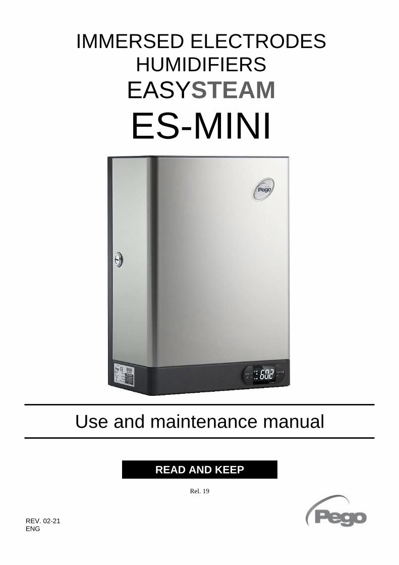
Rel. 19
Use and maintenance manual
READ AND KEEP
REV. 02-21 ENG
IMMERSED ELECTRODES HUMIDIFIERS
EASYSTEAM
ES-MINI

Page 2 Rev. 02-21 USER MANUAL
Thank you for choosing a PEGO EASYSTEAM ES-MINI immersed electrodes humidifier.
The complete reading of this manual will allow you to perform a correct installation and a better use
of the machine. It is therefore advisable to keep this manual in a place adjacent to the humidifier for
any maintenance operations or to modify its operation.
How to read the manual.
To facilitate reading, graphic indications have been inserted with the following meanings:
Indicates a note that require careful reading.
Indicates the operations to be scrupulously performed to avoid damage to the humidifier,
injury to persons or malfunctions.
Indicates the operations not to be performed to avoid damage to the humidifier, injury to
persons or malfunctions.
Indicates a suggestion.
Indicates to contact the PEGO after-sales service center indicated on the back of this
manual.
Instructions for disposal:
The humidifier is made up of metal parts and plastic parts. In reference to European Union directive
2012/19/EC issued on 4 July 2012 and the related national legislation, please note that:
A. WEEE cannot be disposed of as municipal waste and such waste must be collected and
disposed of separately.
B. The public or private waste collection systems defined by local legislation must be used. In
addition, the equipment can be returned to the distributor at the end of its working life when
buying new equipment.
C. The equipment may contain hazardous substances: the improper use or incorrect disposal of
such may have negative effects on human health and on the environment.
D. The symbol (crossed-out wheeled bin) shown on the product or on the packaging and
on the instruction sheet indicates that the equipment has been introduced onto the market
after 13 August 2005 and that it must be disposed of separately.
E. In the event of illegal disposal of electrical and electronic waste, the penalties are specified
by local waste disposal legislation.

Rev. 02-21 Page 3 USER MANUAL
INTRODUCTION
Page 5 1.1 Generality
Page 6 1.2 Warranty conditions
Page 7 1.3 Functioning principle
Page 9 1.4 ES-MINI Series humidifiers identification codes
Page 9 1.5 ES-MINI Series humidifiers technical data
Page 10 1.6 Overall dimensions
Page 10 1.7 Identification data
Page 10 1.8 Standard equipment
INSTALLATION
Page 11 2.1 Main installation warnings
Page 12 2.2 Installing the ES-MINI series humidifier
Page 16 2.3 ES-MINI series humidifiers safety devices and power supply electric connections
Page 16 2.4 ES-MINI series sensors and control signals connections
Page 22 2.5 HUM2 electronic board digital inputs
Page 22 2.6 HUM2 electronic board digital outputs
Page 23 2.7 TA Inputs for measuring current absorption
Page 23 2.8 Net configuration with Modbus-RTU protocol
Page 23 2.9 Board power supply
Page 23 2.10 NANO EasySTEAM Display for Master HUM2 electronic board
Page 24 2.11 ES-MINI series electrical layouts
PROGRAMMING
Page 26 3.1 NANO EasySTEAM Controller description
Page 27 3.2 Combination of keys
Page 28 3.3 Status LED on Master HUM2 electronics
Page 29 3.4 1st Level programming
Page 30 3.5 2st Level programming
MASTER / SLAVE CONFIGURATION
Page 35 4.1 Single humidifier configuration
Page 35 4.2 Master/Slave humidifiers configuration
IGNITING THE HUMIDIFIER
Page 38 5.1 First ignition
Page 38 5.2 Steam production
Page 38 5.3 Smart production for low conductivity
DIAGNOSTICS
Page 39 Diagnostics
TABLE OF CONTENTS
CHAP. 1
CHAP. 2
CHAP. 3
CHAP. 6
CHAP. 4
CHAP. 5

Page 4 Rev. 02-21 USER MANUAL
MAINTENANCE
Page 42 7.1 Maintenance
Page 42 7.2 General and safety Standards
Page 42 7.3 Maintenance intervals
Page 44 7.4 Replacement of the cylinder
Page 46 7.5 Cleaning the cylinder
STEAM DISTRIBUTION
Page 47 8.1 Generality
Page 47 8.2 Example of distribution in air duct
Page 47 8.3 Example of distribution in ambient
Page 48 8.4 Choosing a steam distributor
Page 48 8.5 Condensation recovery
ATTACHMENTS
Page 49 9.1 EU Declaration of Conformity
Page 50 9.2 ES-MINI series spare parts
CHAP. 7
CHAP. 8
CHAP. 9
Rev. 02-21 Page 5 USER MANUAL
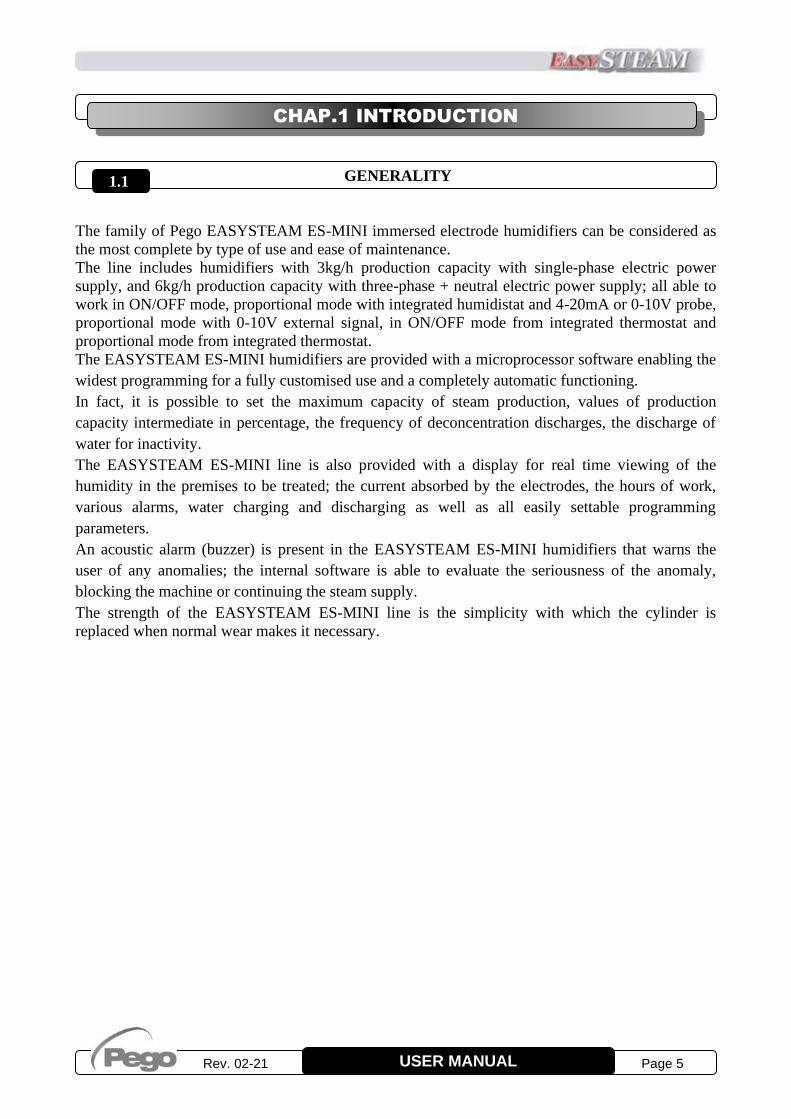
GENERALITY
The family of Pego EASYSTEAM ES-MINI immersed electrode humidifiers can be considered as
the most complete by type of use and ease of maintenance.
The line includes humidifiers with 3kg/h production capacity with single-phase electric power
supply, and 6kg/h production capacity with three-phase + neutral electric power supply; all able to
work in ON/OFF mode, proportional mode with integrated humidistat and 4-20mA or 0-10V probe,
proportional mode with 0-10V external signal, in ON/OFF mode from integrated thermostat and
proportional mode from integrated thermostat.
The EASYSTEAM ES-MINI humidifiers are provided with a microprocessor software enabling the
widest programming for a fully customised use and a completely automatic functioning.
In fact, it is possible to set the maximum capacity of steam production, values of production
capacity intermediate in percentage, the frequency of deconcentration discharges, the discharge of
water for inactivity.
The EASYSTEAM ES-MINI line is also provided with a display for real time viewing of the
humidity in the premises to be treated; the current absorbed by the electrodes, the hours of work,
various alarms, water charging and discharging as well as all easily settable programming
parameters.
An acoustic alarm (buzzer) is present in the EASYSTEAM ES-MINI humidifiers that warns the
user of any anomalies; the internal software is able to evaluate the seriousness of the anomaly,
blocking the machine or continuing the steam supply.
The strength of the EASYSTEAM ES-MINI line is the simplicity with which the cylinder is
replaced when normal wear makes it necessary.
CHAP.1 INTRODUCTION
1.1

Page 6 Rev. 02-21 USER MANUAL
WARRANTY CONDITIONS
The EASYSTEAM series humidifiers are covered by a 24-months warranty against all
manufacturing defects as from the date indicated on the product ID code.
In case of defect the product must be appropriately packaged and sent to our production plant or to
any authorized Service Center with the prior request of the Return Authorization Number.
Customers are entitled to have defective products repaired, spare parts and labor included. The costs
and the risks of transport are at the total charge of the Customer.
Any warranty action does not extend or renew its expiration.
The warranty excludes:
• Damage resulting from tampering, negligence, inexperience or inadequate installation of the
humidifier and its accessories.
• Installation, use or maintenance that does not comply with the prescriptions and instructions
provided with the humidifier.
• Repair work carried out by unauthorized personnel.
• Consumption material (sunk-electrode cylinders)
• Damage due to natural phenomena such as lightning, natural disasters, etc...
In all these cases the costs for repair will be charged to the customer.
The intervention service in warranty can be refused when the equipment is modified or transformed.
Under no circumstances Pego S.r.l. will be liable for any loss of data and information, costs of
goods or substitute services, damage to property, people or animals, loss of sales or earnings,
business interruption, any direct, indirect, incidental, consequential, damaging, punitive, special or
consequential damages, in any way whatsoever caused, whether they are contractual, extra
contractual or due to negligence or other liability arising from the use of the product or its
installation.
Malfunction caused by tampering, bumps, inadequate installation automatically declines the
warranty. It is compulsory to observe all the instructions in this manual and the operating conditions
of the product.
Pego S.r.l. disclaims any liability for possible inaccuracies contained in this manual if due to errors
in printing or transcription.
Pego S.r.l. reserves the right to make changes to its products which it deems necessary or useful
without affecting its essential characteristics.
Each new release of the Pego product user manual replaces all the previous ones.
As far as not expressly indicated, is applicable the Law and in particular the art. 1512 C.C. (Italian
Civil Code).
For any controversy is elected and recognized by the parties the jurisdiction of the Court of Rovigo.
1.2

Rev. 02-21 Page 7 USER MANUAL
FUNCTIONING PRINCIPLE
The immersed electrode humidifiers of the series EASYSTEAM, exploit the conductivity of water
for food use for the production of steam by boiling.
In the cylinder, an electric current is triggered between the immersed electrodes; this overheats the
water until it is brought to the boiling temperature.
The current intensity, expressed in amperes, varies according to the quantity of water present in the
cylinder and in contact with the surface of the electrodes and its conductivity.
The electronics present in the humidifier is able, thanks to an amperometric transformer, to measure
this intensity of current and therefore, by controlling the load solenoid valve to raise the water level
in the cylinder or the drain pump to lower it, it succeeds to control this phenomenon in an
absolutely automatic way.
Furthermore, thanks to a microprocessor technology and to a humidity sensor, proportional
operation can be set, optimizing the consumption of water and electricity according to the humidity
requirements of the environment to be treated.
In addition to ensuring functioning during steam output, the discharge pump also guarantees the
complete cylinder draining when the unit has been inactive for a set time: this prevents the
formation and the deposit of limescale or other particles created during the boiling process.
The humidifiers of the EASYSTEAM series are totally automatic and require only periodic
cleaning of the cylinder and its replacement when the electrodes are worn.
The layout below illustrates the functioning principle.
1.3

Page 8 Rev. 02-21 USER MANUAL
The supplied steam is managed proportionally to steam production request that the electronic
control calculates depending on the
chosen functioning among the eight
available, described in chap. 2.4.
The minimum steam supply is set at
20% of the rated maximum current
(independently of Pr) and is managed
with an activation hysteresis; the
maximum supply, which occurs at a
maximum production request,
corresponds to the percentage set in the
first level variable (Pr). If for example
on an ES6 that produces 6kg/h of
steam, the variable Pr is set to 100%
the maximum production will be 6kg/h;
but if the variable Pr is reduced to 50%,
the maximum production will be 3kg/h.
For correct operation, the humidifier must be supplied with drinking water coming from the
aqueduct; this is because it is free from any element harmful to health and is compatible with
the range of conductivity useful for optimal operation of the humidifier. However, in some
geographical areas mains water may be unsuitable for optimal functioning due to very low
conductivity or high hardness or because it’s too aggressive; the below is a summary table of the
parameters required for correct humidifier functioning.
POTABLE WATER FUNCTIONING RANGE
LIMITS
with standard
cylinder
LIMITS with cylinder
for low conductivity
PARAMETER UNIT OF
MEASURE MIN OPT MAX MIN OPT MAX
Water conductivity at 20°C * S/cm 250 400 1300 125 200 350
pH 7 8 8,5 7 8 8,5
Hardness mg/l CaCO3 160 200 450 60 120 160
Chlorine ppm Cl2 0 0 0,2 0 0 0,2
Chlorides mg/l Cl- 0 <25 250 0 <20 100
Calcium sulphate mg/l CaSO4 0 0 95 0 0 55
Metal impurities / Solvents / Soaps / Lubricants mg/l 0 0 0 0 0 0
Temperature °C +1 +20 +40 +1 +20 +40
MIN = minimum - OPT = optimal - MAX = maximum
* Water conductivity is always expressed at 20°C; bear in mind that conductivity decreases as water
temperature drops and so water may not be very conductive during winter when mains water is
particularly cold.
In case of very low conductivity, consult chapter 5.3 on page 38 of this manual: Intelligent
production for low conductivity.
Do not supply the humidifier with well water or treated with osmosis purifiers,
demineralisers or softeners or taken from cooling circuits.
Minimum supply
Steam production request
Supplied steam
Maximum supply

Rev. 02-21 Page 9 USER MANUAL
ES-MINI SERIES HUMIDIFIERS IDENTIFICATION CODES
400ES3MMINI Single-phase humidifier with stainless steel casing, with 3kg/h steam
production capacity, integrated electronics with ten selectable operating
modes.
400ES6MINI Three-phase humidifier with stainless steel casing, with 6kg/h steam
production capacity, integrated electronics with ten selectable operating
modes.
ES-MINI SERIES HUMIDIFIERS TECHNICAL DATA
TECHNICAL DATA AND
WORKING CONDITIONS 400ES3MMINI 400ES6MINI
STEAM PRODUCTION (in kg/h) 3 6
ELECTRIC POWER SUPPLY 230V 50Hz * 400V 3/N 50Hz *
POWER (kW) 2 4,5
ABSORBED CURRENT (A) 9 6,5
TYPE OF CONTROL Display NANO + Master HUM2 EASYSTEAM series
ELECTRONIC CONTROL POWER SUPPLY 230V 50-60Hz
STEAM OUTLET DIAMETER (mm) 25 25
CYLINDERS NUMBER 1 1
VACUUM WEIGHT (kg) 8 8
WEIGHT WITH OPERATIONAL UNIT (kg) 11,5 11,5
WATER SUPPLY PRESSURE 1-10 bar
FUNCTIONING AMBIENT TEMP. +1 ÷ +40 °C
FUNCTIONING AMBIENT HUMIDITY < 60 %RH (90 %RH non condensing)
STORAGE TEMPERATURE -10 ÷ +70 °C
PROTECTION RATING IP20
* 60Hz VERSION AVAILABLE ON REQUEST
1.4
1.5
Page 10 Rev. 02-21 USER MANUAL
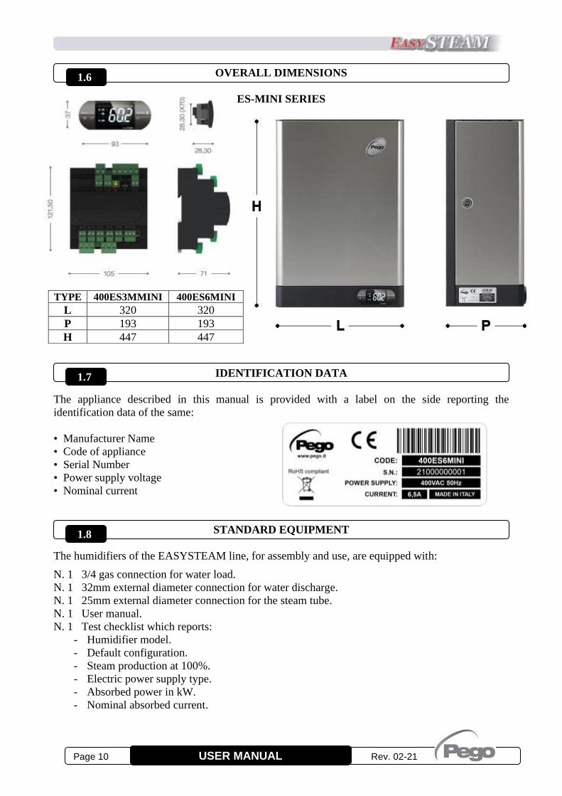
OVERALL DIMENSIONS
ES-MINI SERIES
IDENTIFICATION DATA
The appliance described in this manual is provided with a label on the side reporting the
identification data of the same:
• Manufacturer Name
• Code of appliance
• Serial Number
• Power supply voltage
• Nominal current
STANDARD EQUIPMENT
The humidifiers of the EASYSTEAM line, for assembly and use, are equipped with:
N. 1 3/4 gas connection for water load.
N. 1 32mm external diameter connection for water discharge.
N. 1 25mm external diameter connection for the steam tube.
N. 1 User manual.
N. 1 Test checklist which reports:
- Humidifier model.
- Default configuration.
- Steam production at 100%.
- Electric power supply type.
- Absorbed power in kW.
- Nominal absorbed current.
TYPE 400ES3MMINI 400ES6MINI
L 320 320
P 193 193
H 447 447
1.6
1.7
1.8
KIT ELETTRONICA

Rev. 02-21 Page 11 USER MANUAL
MAIN INSTALLATION WARNINGS
1. The installation, maintenance and use of the appliance must be carried out by qualified
personnel able to safely perform the requested operations. Carefully read this manual before
performing any operations and follow all its indications.
2. Install the appliance as close as possible to the environment where the steam is to be
introduced, namely in the position that guarantees the shorter length of the steam tube. We
recommend not to exceed 5 meters.
3. Install the appliance at a height that allows easy access to the control unit for parameter
adjustment and viewing of the display. We recommend a height from the ground of about 1
meter.
4. Install the appliance at a height that allows easy access to the inside of the humidifier for
cylinder replacement.
5. Some parts of the humidifier, during operation, may exceed the temperature of 60°C. Make
sure that the surfaces in contact with the humidifier are compatible with these values.
6. Do not install and use the humidifier near products or objects that can be damaged in contact
with water or the humidity produced.
7. Avoid placing power cables with signal cables in the same conduit (probes and digital
inputs).
8. Reduce the lengths of the connecting cables as much as possible, avoiding that the wiring
takes up the spiral shape, which is harmful for possible inductive effects on the electronics.
9. Install a magneto thermal protection switch, upstream of the humidifier.
10. All conductors used in the wiring must be appropriately proportioned to support the load they
are to supply.
11. If it is necessary to extend the probe, it is necessary to use conductors with a suitable section
and in any case not less than 1mm2.
12. Connect a pipe with a diameter of not less than 32mm to the drain hose. This pipe must be
firmly clamped to the drain sleeve and have vertical development for at least the first 50cm.
Make sure that you do not create bottlenecks and do not exceed the height at any point in the
path, the level of the drain sleeve.
13. Use only drinking water for the water load, with a pressure between 1 and 10 bar.
14. Check the default setting shown on the enclosed TEST CHECKLIST, before starting up the
humidifier. If the default setting is different from your needs, set the parameters as indicated
in chapter 3 and in accordance with the connections indicated in chapter 2.4.
15. With the default setting of parameter In1=2, the humidifier to work requires the digital input
1 to be enabled by means of a voltage free contact (terminals 24 and 25 on the electronic
board Master HUM2) regardless of the selected operating mode.
16. If it is not necessary to use an external enable, jumper the terminals 24 and 25 on the Master
HUM2 electronic board or set the parameter In1=0.
17. Without enabling, the display alternates the word OFF with normal displaying.
CHAP. 2 INSTALLATION
2.1

Page 12 Rev. 02-21 USER MANUAL
INSTALLING THE ES-MINI SERIES HUMIDIFIER
1. Remove the humidifier from its packaging keeping it upright, remove the protective nylon bag
and check the integrity of the appliance.
2. With a screwdriver, unlock the safety locks on the sides of the front cover (fig. 1 e 2).
Fig. 1 Fig. 2
3. Remove the front cover by gripping it on the sides and slightly pulling towards you (fig. 3).
Fig. 3
2.2

Rev. 02-21 Page 13 USER MANUAL
4. Fix the humidifier to the wall, at least 1 meter from the ground and leveled (fig.4) using the four
slots at the back to insert the fixing screws (fig. 5 e 6).
Fig. 4
Fig. 5 Fig. 6
Page 14 Rev. 02-21 USER MANUAL
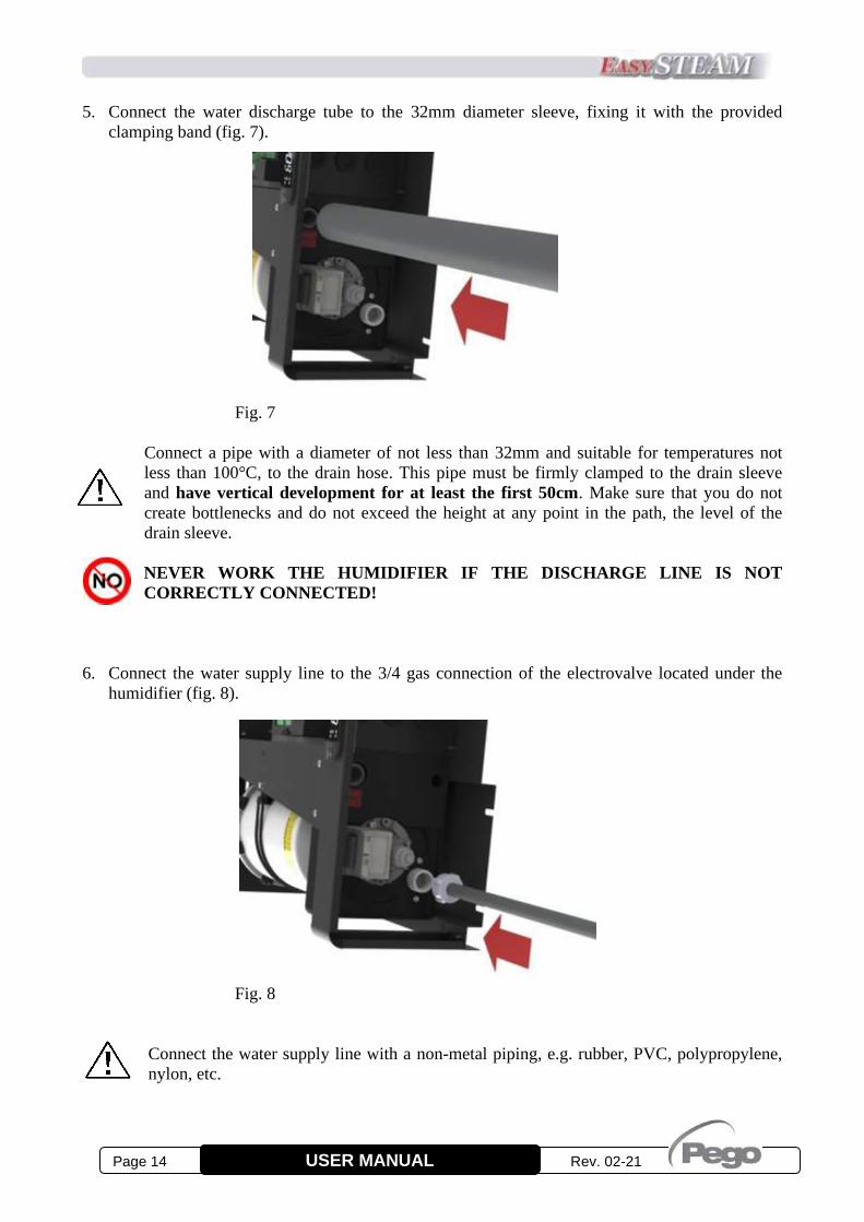
5. Connect the water discharge tube to the 32mm diameter sleeve, fixing it with the provided
clamping band (fig. 7).
Fig. 7
Connect a pipe with a diameter of not less than 32mm and suitable for temperatures not
less than 100°C, to the drain hose. This pipe must be firmly clamped to the drain sleeve
and have vertical development for at least the first 50cm. Make sure that you do not
create bottlenecks and do not exceed the height at any point in the path, the level of the
drain sleeve.
NEVER WORK THE HUMIDIFIER IF THE DISCHARGE LINE IS NOT
CORRECTLY CONNECTED!
6. Connect the water supply line to the 3/4 gas connection of the electrovalve located under the
humidifier (fig. 8).
Fig. 8
Connect the water supply line with a non-metal piping, e.g. rubber, PVC, polypropylene,
nylon, etc.

Rev. 02-21 Page 15 USER MANUAL
7. Connect the steam tube at the cylinder flange sleeve, fixing it with the provided clamping band
(fig. 9).
Fig. 9
Use only PEGO HUMIDIFIERS steam tube or other tube with certification that
guarantees its use in the presence of high temperatures without internal vulcanization
processes and release of harmful substances!
DO NOT MAKE BOTTLENECKS, SIPHONS OR LENGTHS GREATER THAN 5
METERS!
To correctly connect the steam distribution line, carefully read chapter 8, STEAM
DISTRIBUTION.
Page 16 Rev. 02-21 USER MANUAL
ES-MINI SERIES HUMIDIFIERS SAFETY DEVICES
AND POWER SUPPLY ELECTRIC CONNECTIONS
Connect the electric power supply to the humidifier terminal board, bringing 230V 50Hz
voltage to clamps R and N for single-phase models, or 400V 50Hz voltage + neutral to the
RST and N clamps for the three-phase models.
It is mandatory to connect the terminal marked by the yellow / green colour and the initials PE to
the ground system of the electrical supply network. If necessary, check the efficiency of the
earthing system.
Leave the jumper in terminals 60 and 61 of the terminal board or replace it, if necessary, with a
normally closed emergency contact.
The terminals 62 and 63 of the terminal board (output DO5) are already wired, in tension. The
electronics are preconfigured to use this output to supply the fan-assisted distributor head (in case,
consult the user manual attached to it). By changing the setting of parameter dO5 it is possible
otherwise to use this output for other functionalities.
ES-MINI SERIES SENSORS AND CONTROL SIGNALS CONNECTIONS
The humidifier has ten different operating modes that can be set by the software variable S9
described in chapter 3.5 and by specific electrical connections.
It is also necessary to enable the digital input In1 terminals 24 and 25 on the electronic board
Master HUM2 for all operating modes (enabling = closed contact between clamps 24 and 25). See
the parameter settings In1, In2 and In3 for all possible enablements. Without enabling, the display
alternates the OFF writing with normal displaying.
Below are the specific connections for every functioning mode.
If you want to connect the humidifier with a humidity probes not supplied by PEGO s.r.l.,
contact the after-sales assistance to verify the hardware compatibility between the probe
and the humidifier.
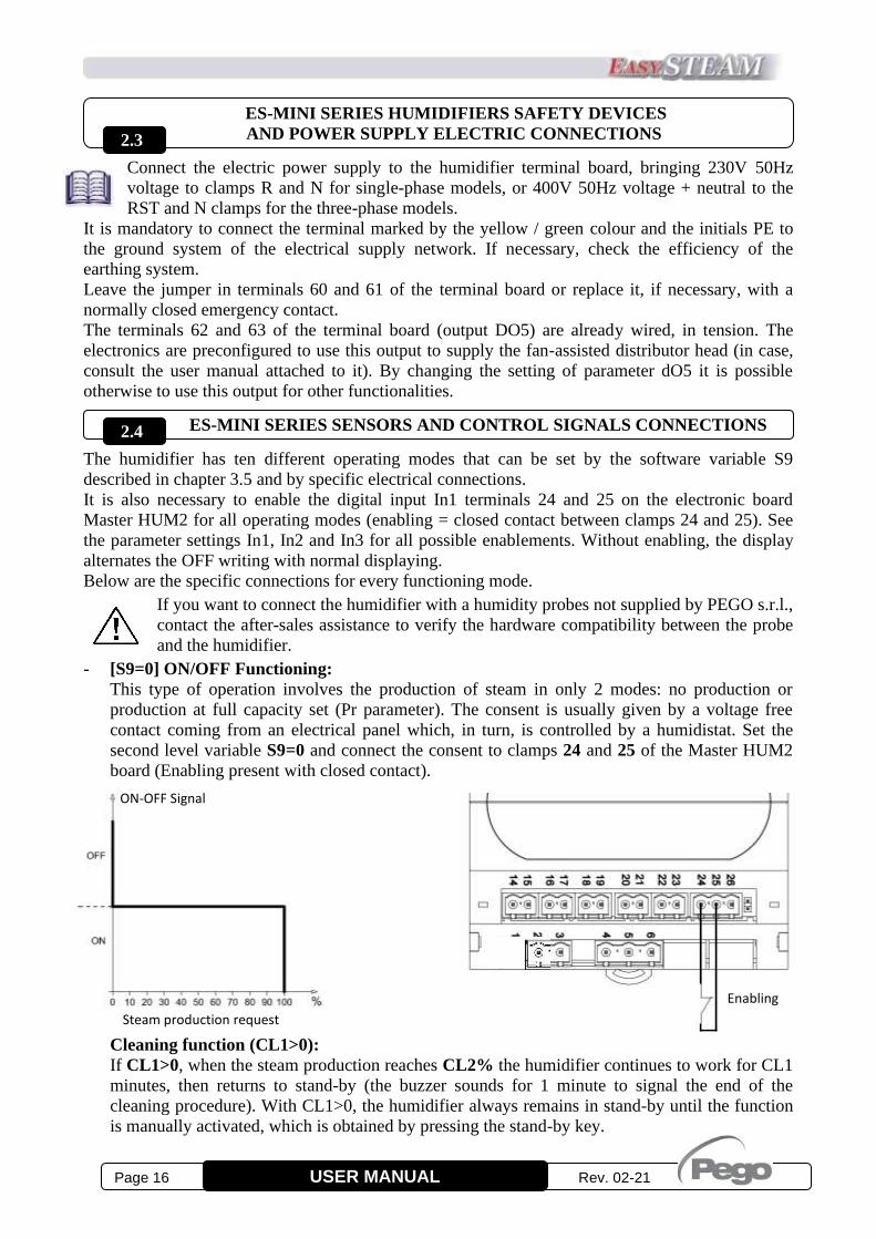
- [S9=0] ON/OFF Functioning:
This type of operation involves the production of steam in only 2 modes: no production or
production at full capacity set (Pr parameter). The consent is usually given by a voltage free
contact coming from an electrical panel which, in turn, is controlled by a humidistat. Set the
second level variable S9=0 and connect the consent to clamps 24 and 25 of the Master HUM2
board (Enabling present with closed contact).
Cleaning function (CL1>0):
If CL1>0, when the steam production reaches CL2% the humidifier continues to work for CL1
minutes, then returns to stand-by (the buzzer sounds for 1 minute to signal the end of the
cleaning procedure). With CL1>0, the humidifier always remains in stand-by until the function
is manually activated, which is obtained by pressing the stand-by key.
2.3
ON-OFF Signal
Steam production request
2.4
Enabling
Rev. 02-21 Page 17 USER MANUAL
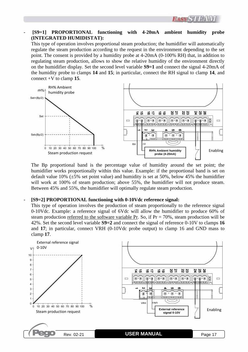
- [S9=1] PROPORTIONAL functioning with 4-20mA ambient humidity probe
(INTEGRATED HUMIDISTAT):
This type of operation involves proportional steam production; the humidifier will automatically
regulate the steam production according to the request in the environment depending to the set
point. The consent is provided by a humidity probe at 4-20mA (0-100% RH) that, in addition to
regulating steam production, allows to show the relative humidity of the environment directly
on the humidifier display. Set the second level variable S9=1 and connect the signal 4-20mA of
the humidity probe to clamps 14 and 15; in particular, connect the RH signal to clamp 14, and
connect +V to clamp 15.
-
-
-
The Bp proportional band is the percentage value of humidity around the set point; the
humidifier works proportionally within this value. Example: if the proportional band is set on
default value 10% (±5% set point value) and humidity is set at 50%, below 45% the humidifier
will work at 100% of steam production; above 55%, the humidifier will not produce steam.
Between 45% and 55%, the humidifier will optimally regulate steam production.
- [S9=2] PROPORTIONAL functioning with 0-10Vdc reference signal:
This type of operation involves the production of steam proportionally to the reference signal
0-10Vdc. Example: a reference signal of 6Vdc will allow the humidifier to produce 60% of
steam production referred to the software variable Pr. So, if Pr = 70%, steam production will be
42%. Set the second level variable S9=2 and connect the signal of reference 0-10V to clamps 16
and 17; in particular, connect VRH (0-10Vdc probe output) to clamp 16 and GND mass to
clamp 17.
RH% Ambient humidity probe
Steam production request
External reference signal 0-10V
Enabling
GND VRH
Enabling RH% Ambient humidity probe (4-20mA)
RH +V
External reference signal 0-10V
Steam production request

Page 18 Rev. 02-21 USER MANUAL
- [S9=3] PROPORTIONAL functioning with 4-20mA ambient humidity probe + 4-20mA
humidity probe in air duct (INTEGRATED HUMIDISTAT):
This type of operation involves proportional steam production; the humidifier will automatically
regulate the steam production according to the request in the environment depending to the set
point and to the value measured in duct.
Set the second level variable S9=3, connect the 4-20mA signal of ambient humidity probe
(0-100%RH) to clamps 14 and 15; in particular, connect RH signal to clamp 14 and +V to
clamp 15. Connect 4-20mA signal of humidity probe in air duct (0-100%RH) to clamps 20 and
21; in particular, connect signal RH to clamp 20 and +V to clamp 21. For further information on
the humidity probe in air duct, refer to chapter 3 “Programming” (variables StC, r0, t1).
- [S9=4] PROPORTIONAL functioning with 0-10Vdc reference signal + humidity probe in
air duct (4-20mA):
This type of operation involves the production of steam proportionally to the 0-10Vdc reference
signal and to the humidity measured in duct.
Set the second level variable S9=4 and connect the 0-10Vdc reference signal to clamps 16 and
17; in particular, connect VRH to clamp 16 and GND mass to clamp 17. Connect 4-20mA
signal of humidity probe in air duct (0-100%RH) to clamps 20 and 21; in particular, RH signal
to clamp 20 and +V to clamp 21.
For further information on the humidity probe in air duct, refer to chapter 3 “Programming”
(variables StC, r0, t1).
Enabling RH% humidity probe
in air duct (4-20mA)
External reference signal 0-10V
RH +V GND VRH
Enabling RH% Ambient humidity probe (4-20mA)
RH% humidity probe in air duct (4-20mA)
RH +V RH +V
Rev. 02-21 Page 19 USER MANUAL
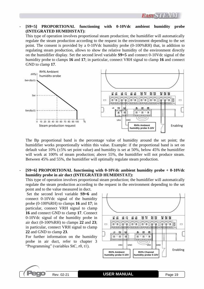
- [S9=5] PROPORTIONAL functioning with 0-10Vdc ambient humidity probe
(INTEGRATED HUMIDISTAT):
This type of operation involves proportional steam production; the humidifier will automatically
regulate the steam production according to the request in the environment depending to the set
point. The consent is provided by a 0-10Vdc humidity probe (0-100%RH) that, in addition to
regulating steam production, allows to show the relative humidity of the environment directly
on the humidifier display. Set the second level variable S9=5 and connect 0-10Vdc signal of the
humidity probe to clamps 16 and 17; in particular, connect VRH signal to clamp 16 and connect
GND to clamp 17.
-
-
-
The Bp proportional band is the percentage value of humidity around the set point; the
humidifier works proportionally within this value. Example: if the proportional band is set on
default value 10% (±5% set point value) and humidity is set at 50%, below 45% the humidifier
will work at 100% of steam production; above 55%, the humidifier will not produce steam.
Between 45% and 55%, the humidifier will optimally regulate steam production.
- [S9=6] PROPORTIONAL functioning with 0-10Vdc ambient humidity probe + 0-10Vdc
humidity probe in air duct (INTEGRATED HUMIDISTAT):
This type of operation involves proportional steam production; the humidifier will automatically
regulate the steam production according to the request in the environment depending to the set
point and to the value measured in duct.
Set the second level variable S9=6 and
connect 0-10Vdc signal of the humidity
probe (0-100%RH) to clamps 16 and 17; in
particular, connect VRH signal to clamp
16 and connect GND to clamp 17. Connect
0-10Vdc signal of the humidity probe in
air duct (0-100%RH) to clamps 22 and 23;
in particular, connect VRH signal to clamp
22 and GND to clamp 23.
For further information on the humidity
probe in air duct, refer to chapter 3
“Programming” (variables StC, r0, t1).
RH% Ambient humidity probe
Steam production request RH% Ambient humidity probe 0-10V
Enabling
GND VRH
RH% Ambient humidity probe 0-10V
Enabling
GND VRH GND VRH
RH% Channel humidity probe 0-10V

Page 20 Rev. 02-21 USER MANUAL
- [S9=7] Functioning with integrated thermostat (ON/OFF hot call):
This type of operation involves the production of steam in only 2 modes: no production or
production at full capacity set (Pr parameter) which is activated when the temperature measured
by the ambient probe falls below the value of SET POINT-r1 and remains active until the
temperature increases and exceeds the SET POINT.
Set the second level variable S9=7 and connect the NTC temperature probe to clamps 18 and 19
of the Master HUM2 electronic board (r1=Temperature differential referred to set point).
In this mode, it is possible to set the two configurable outputs (Do4 and Do5 already wired on
terminals 62 and 63, in tension) to manage a few typical functions of a sauna or a Turkish bath,
such as the essence inlet, the management of outlet or inlet fans.
Essence Management (dO4 or dO5 = 4):
In a Turkish bath the essence is provided (with the times set in t2 and t3) when the humidifier is
producing steam and the temperature measured by the ambient probe is higher than 70% of the
set point. By using the key combination arrow up + Stand-by is possible at any time to enable or
disable the inlet of the essence; in particular, the current status is displayed after pressing the
key combination for three seconds (EoF = essence OFF or Eon = essence ON) and by
continuing to hold the keys pressed for another three seconds, the state is switched.
Inlet fan (dO4 or dO5 = 3):
The inlet fan is usually used to introduce or mix the steam in the room. The relay linked to this
function is activated when there is a steam production request (it remains active even during the
phases of water discharge for deconcentration or due to overcurrent) and it is deactivated with
the delay set in parameter t6 after the end of the steam production request. If parameter t6 is set
to -1, the inlet fan run in continuous gear (active even during stand-by or alarms).
Outlet fan (dO4 or dO5 = -3):
The outlet fan is usually used to ensure air exchange and to create the fog effect. The relay
linked to this function is activated when there is no steam production request. It is also possible
to start a drying cycle at the end of the day; with the humidifier in stand-by, press the keys
arrow down + Stand-by to activate the cycle that is indicated on the display with the writing
Uon = outlet fans ON. In this phase the output of the outlet fan remains active for the hours set
in the variable t4. To stop this cycle, simply exit the stand-by status.
Cleaning function (CL1>0): If CL1>0, when the temperature reaches the setpoint the humidifier continues to work for CL1
minutes, then returns to stand-by (the buzzer sounds for 1 minute to signal the end of the cleaning
procedure). With CL1>0, the humidifier is always in stand-by until the function is manually
activated, which is obtained by pressing the stand-by key.
Ambient temperature
Steam production request
Enabling
NTC Ambient temperature probe

Rev. 02-21 Page 21 USER MANUAL
- [S9=8] PROPORTIONAL functioning REFERRED TO VALUE SENT ON RS485
(0-100%):
This type of operation involves the production of steam proportionally to the value set in
register 1537 by means of Modbus-RTU communication.
In this operating mode, the commands to force water discharge and produce steam have a time-
out of 1 minute; if during this period the
command is not sent again on Modbus, at the end
of this time the steam production will be set to
zero and the drain pump will be disabled.
This secures the humidifier in case of accidental
disconnection of the communication network.
Set the second level variable S9=8 and connect
the instrument to the RS485 line with clamp 32
to line A (TX+) and clamp 31 to line B (TX-).
For further information on Modbus-RTU
Protocol of the humidifier, refer to document
“MODBUS-RTU_UMIDMS03”.
- [S9=9] PROPORTIONAL functioning with NTC ambient temperature probe
(INTEGRATED THERMOSTAT):
This type of operation involves proportional steam production; the humidifier will automatically
regulate the steam production according to the request in the environment depending to the set
point. The consent is provided by a NTC ambient probe that, in addition to regulating steam
production, allows to show the ambient temperature directly on the humidifier display. Set the
second level variable S9=9 and connect the NTC temperature probe to clamps 18 and 19 of the
Master HUM2 electronic board.
-
-
-
The 2*r1 proportional band is the value in degrees Celsius (°C) around the temperature set
point; within this band the humidifier works proportionally.
Essence Management (dO4 or dO5 = 4):
See mode S9=7.
Inlet fan (dO4 or dO5 = 3):
See mode S9=7.
Outlet fan (dO4 or dO5 = -3):
See mode S9=7.
Cleaning function (CL1>0):
See mode S9=7.
B A
Steam production request
Enabling
NTC Probe Ambient temperature
°C Ambient Temperature Set + r1
Set - r1

Page 22 Rev. 02-21 USER MANUAL
HUM2 ELECTRONIC BOARD DIGITAL INPUTS
On the electronics of the humidifier there are four digital inputs with the following meaning:
Digital inputs In1, In2 are in low voltage.
Input In1 (clamps 24 and 25): input with configurable meaning based on the second level
variable In1. By default, this input is configured as "main enable": enable with closed contact
between terminal 24 and 25.
Input In2 (clamps 24 and 26): input with configurable meaning based on the second level
variable In2. the input is active when the contact between terminals 24 and 26 is closed or by
means of the jumper on the board, next to terminal 26. By default, this input is configured as
"discharge pump activation" to enable emptying the cylinder in case the console is not present.
Digital inputs In3, In4 are in high alternate voltage (mains voltage).
These inputs hear the mains voltage and for their
operation require the connection of one of the two
phases (in our case the neutral) to the clamp 4.
Input In3 (clamps 4<neutral> and 6<phase> ):
input with configurable meaning based on the
second level variable In3. The input is active with
phase input to clamp 6.
Input In4 (clamps 4<neutral> and 5<phase> ):
input for maximum water level in the cylinder,
active with phase input to clamp 5.
In ES series humidifiers input In4 is already wired.
If none of the inputs In1, In2 and In3 are configured
as enablement, the humidifier does not need external
enabling to operate.
HUM2 ELECTRONIC BOARD DIGITAL OUTPUTS
On the electronics of the humidifier there are five relays, two of which with configurable function.
The digital outputs Do1, Do2, Do3 and Do5 are normally open contacts with a single common
(terminal 9) while the output Do4 is independent and galvanically isolated, in particular:
Output Do1 (clamps 9 and 10): Electrodes.
Output Do2 (clamps 9 and 11): Water load EV.
Output Do3 (clamps 9 and 12): Discharge pump.
Output Do5 (clamps 9 and 13): Configurable
relay, already wired on terminals 62 and 63 of the
humidifier, in tension (230Vac 50Hz).
Output Do4 (clamps 7 and 8): Configurable relay.
By default, this output is set as alarm relay (second
level variable (second level variable dO4 = 1).
Relay capacity characteristics:
Do1, Do2, Do3: 16(6)A 250Vac
Do4, Do5: 8(3)A 250Vac
In the ES series humidifiers, the outputs Do1, Do2, Do3 and Do5 are already wired.
2.5
2.6
In1 In2
In4 In3 Phase
N
Do
5
Do
3
Do
2
Do
1
Do
4

Rev. 02-21 Page 23 USER MANUAL
TA INPUTS FOR MEASURING CURRENT ABSORPTION
On the electronics of the humidifier there are two inputs from an amperometric transformer, to
measure the current of the immersed electrodes:
TA1 (clamps 27 and 28): For the connection of the TA, relative to the cylinder Nr 1
TA2 (clamps 29 and 30): For the connection of the TA, relative to the cylinder Nr 2
NET CONFIGURATION WITH MODBUS-RTU PROTOCOL
To insert the humidifier in an RS485 network with Modbus-RTU protocol, set the parameter
MS = 0 (single humidifier operating mode), and follow the diagram below.
Refer to the MODBUS-RTU_UMIDMS03 manual (available on our website: www.pego.it) for
MODBUS-RTU communication protocol specifications.
BOARD POWER SUPPLY
The humidifier electronics require a 230Vac 50-60Hz ±10% power supply and have a maximum
consumption of 5VA (only electronic part).
Power supply (clamps 2 and 3): 230Vac 50-60Hz power supply.
NANO EASYSTEAM DISPLAY FOR MASTER HUM2 ELECTRONIC BOARD
The Master HUM2 electronics is the heart of the humidifier, which can be combined with a NANO
EasySTEAM display that allows the display of the machine status, programming and configuration
of the parameters. The connection between the display and the Master is made by a cable with an
8-pin RJ45 telephone connector with cross-over connection (supplied together with the display) to
be inserted in the two J1 references.
The combined use of Master and display is the most complete and recommended method but not the
only one possible; once configured, the Master HUM2 electronics does not require the presence of
the display and can be used independently. It is also provided with status LED (see chapter 3.2) and
a switch (jumper) for the manual emptying of the cylinder (see chapter 2.5). In this single mode, the
alarms are reset by removing power to the electronics.
2.7
2.9
2.10
B A
2.8

Page 24 Rev. 02-21 USER MANUAL
ES-MINI SERIES ELECTRICAL LAYOUTS
- Electrical layout model:
400ES3MMINI
2.11
Fan u
nit
Level
Hu
mid
ifier ele
ctrod
es
Electric
con
nectio
ns to
the cylin
der
Po
wer term
inal
blo
ck
Co
nsen
ts and
pro
bes
termin
al bo
x
LE
GE
ND
:
KM
1: C
on
tacto
r
TA
1: A
mp
erom
etric Tra
nsfo
rmer
P1: E
xh
au
st Pu
mp
EV
1: L
oad
Valv
e
Po
we
r sup
ply
23
0V
ac single
ph
ase 50
Hz
CONSOLE
Clo
sed em
ergency
con
tact

Rev. 02-21 Page 25 USER MANUAL
- Electrical layout model:
400ES6MINI
Co
nsen
ts and
pro
bes
termin
al bo
x CONSOLE
Po
we
r sup
ply
40
0V
ac three
ph
ases + n
eutral 5
0H
z
Fan u
nit
Clo
sed em
ergency
con
tact
Level
Hu
mid
ifier ele
ctrod
es
Electric
con
nectio
ns to
the cylin
der
Po
wer term
inal
blo
ck L
EG
EN
D:
KM
1: C
on
tacto
r
TA
1: A
mp
erom
etric Tra
nsfo
rmer
P1: E
xh
au
st Pu
mp
EV
1: L
oad
Valv
e

Page 26 Rev. 02-21 USER MANUAL
NANO EASYSTEAM CONTROLLER DESCRIPTION
The NANO EasySTEAM display is normally placed on the front of the humidifier. It consists of a
display with 3 digits and 9 luminous icons, for visual control of the magnitudes, and 4 keys for
choose the view and modify the settings (fig. 25).
Fig. 25
UP / DISPLAY KEY - During programming: Increase values / Scroll up the parameters
- During the main display: Selects view between: "absorbed current (A)", "steam production %
(%)", "Ambient humidity display (%RH)" or "Ambient temperature display (°C)".
Each time it is pressed, it switches to the next display.
DOWN / MANUAL WATER DISCHARGE KEY - During programming: Decrease values / Scroll down the parameters.
- During the main display: Activates the manual water discharge.
STAND BY / SILENCE - Pressed for more than 2 seconds alternates the Stand-by status to the normal functioning
status, and vice-versa. At occurred switching, a confirmation BIP is generated.
- Silences the audible alarm, if in progress / Acquires an alarm.
SET (active with S9 = 1, 3, 5, 6, 7, 9) - When pressed, displays the setpoint and when released "Ambient humidity display (% HR)"
or "Ambient temperature display (°C)".
- It allows to set the %HR or °C set point, if pressed together with the Down key or the UP key
- Reset the audible alarm, if in progress.
DISPLAY
STAND-BY ICON LED OFF = Humidifier not powered.
LED ON = Humidifier ready for use.
LED Flashing = Humidifier in stand-by.
STEAM OUTPUT ICON LED ON = Steam production in progress.
CHAP. 3 PROGRAMMING
3.1

Rev. 02-21 Page 27 USER MANUAL
ALARM PRESENCE ICON LED OFF = No alarm present.
LED ON = Maximum level alarm, persistent for longer than 1 hour.
LED Flashing = Alarm present (or maximum level reached).
TEMPERATURE MEASUREMENT UNITS ICON LED ON = The display shows the temperature of the ambient probe in °C.
LED Flashing = The display shows the TEMPERATURE SET in °C.
WATER LOAD ICON LED ON = Water load in progress.
WATER DISCHARGE ICON LED ON = Water discharge in progress.
LED Flashing= Water discharge test in progress.
CURRENT MEASUREMENT UNITS ICON (A) LED ON = The display shows in ampere the instantaneous current absorbed by the humidifier.
STEAM PRODUCTION % MEASUREMENT UNITS ICON LED ON = The display shows the percentage production of steam, referred to the nominal one
(example: for an ES6 that produces 6kg/h of steam, 50% indicates the current production of
3kg/h).
RELATIVE HUMIDITY MEASUREMENT UNITS ICON THIS ICON LIGHTS TOGETHER WITH (13) AND "% RH" APPEARS ON THE DISPLAY
LED ON = The display shows the percentage of relative humidity of the connected probe.
LED Flashing = The display shows the percentage relative humidity SET (visible and
adjustable by pressing the SET key).
COMBINATION OF KEYS
+
1ST LEVEL PROGRAMMING If pressed simultaneously for more than 3 seconds, they allow access to the first
level programming menu.
At the entry of the menu it is generated a confirmation BEEP.
EXIT FROM PROGRAMMING If pressed simultaneously for more than 3 seconds in any programming menu, they
save the settings by exiting the menu.
At the exit of the menu it is generated a confirmation BEEP.
+
+
2ND LEVEL PROGRAMMING If pressed simultaneously for more than 3 seconds, they allow access to the second
level programming menu.
At the entry of the menu it is generated a confirmation BEEP.
+
STATUS SWITCHING OF THE ESSENCE SUPPLY (function active only if s9 = 7 or 9 and dO4 or dO5 = 4)
If pressed simultaneously for more than 3 seconds, the current status is displayed
(EoF=essence OFF or Eon=essence ON) and continuing to hold them pressed for
an additional three seconds, the status switches.
+
DRYING ACTIVATION (function active only if s9 = 7 or 9 and dO4 or dO5 = -3 and stand-by active)
If pressed simultaneously for more than 3 seconds, the drying cycle is activated
and signalled on display by the writing Uon = outlet fans ON.
To stop this cycle, interrupt the stand-by.
3.2

Page 28 Rev. 02-21 USER MANUAL
STATUS LED ON MASTER HUM2 ELECTRONICS
On the Master HUM2 electronics, next to the J1 connector there are three signalling LEDs that
allow to know the machine status even in the absence of a display.
GREEN LED initialled P (Power):
Solid: power supply Ok and consent is present.
Flashing: power supply Ok but no consent or stand-by present.
YELLOW LED initialled S (Status):
Solid: Steam production (powered electrodes).
Flashing: Discharge in progress. (0.5 seconds flashes).
RED LED initialled A (Alarm):
When an alarm is present, it is signalled with a sequence of
flashes spaced by 0.5 seconds of a number equal to the error
code and with a pause of 2 seconds before repeating the
sequence.
3.3

Rev. 02-21 Page 29 USER MANUAL
1ST LEVEL PROGRAMMING
1. The 1st level programming allows the user to modify 2 important parameters: the proportional
band Bp and the percentage of steam production Pr.
VAR. MEANING VALUES DEFAULT
all models
Pr Steam production percentage 20 ÷ 100 % 100 %
Bp Proportional band (not used in ON/OFF version) 1 ÷ 20 Rh% 10 %
StC
Max humidity set point in air duct.
When the set point is exceeded, the humidifier is set to off and resumes
operation when the humidity in the air duct drops below the value StC-r0
with the addition of time t1, according to the logic dictated by the 0-10V
signal or from the ambient humidity probe.
25 ÷ 99 Rh% 99%
r0 Max humidity set differential in air duct. 1 ÷ (StC – 20) Rh% 50%
r1
Temperature differential referred to set point.
For temperature values lower than set-r1, the humidifier is activated until the
set point is reached (call of heat). If S9=9, r1 is the proportional band.
(used only with S9=7 or S9=9 call of heat version)
0.2 – 10 °C 2°C
UrC Humidity value read by the humidity probe in air duct. 0-100% read only
PrL Percentage of steam production during operation with low conductivity
(with S11=1 Pr is ignored) 0-100% read only
The Bp proportional band is the percentage value of the humidity around the set point;
within this value the humidifier works proportionally. Example: if the proportional band is
set on default value 10% (±5% set point value) and humidity is set at 50%, below 45% the
humidifier will work at 100% of steam production; above 55%, the humidifier will not produce
steam. Between 45 and 55%, the humidifier will optimally regulate steam production.
The Pr steam percentage is the value the humidifier can reach at maximum production; leaving
setting at 100%, an ES6 with 6kg/h steam production, can reach 6kg/h, if Pr setting is reduced to
50%, the humidifier can produce a maximum of 3kg/h.
The variable Pr is very useful in cases of low conductivity of water and to make the most
of the cylinder when it is near to replacement; for further information consult chapter 6
DIAGNOSTICS on page 39 of this manual.
The set point of maximum humidity in the duct (stC) limits the humidity in the duct.
If the humidity in the duct is higher than the value set in stC, the humidifier stops the steam
production. When the humidity returns below stC-r0, at the end of the delay time t1 (second level
variable) the steam production is resumed.
2. To access the first level programming menu, follow the instructions below:
- Press and hold down the UP () and DOWN () keys simultaneously for a few seconds until
the first programming variable appears on the display.
- Release () and () keys.
- Use the () key or the () key to select the variable to be modified.
- After selecting the desired variable, it will be possible:
- Display its settings by pressing the SET key.
- Change its settings by holding down the SET button and pressing one of the () or () keys.
Once you have finished configuring the values, press the keys () and () for a few seconds to
exit the menu and keep them pressed until the magnitudes displayed before entry into programming
reappears, e.g. steam production or absorbed current. The memorization of the changes made to the
variables will occur automatically when exiting the configuration menu.
3.4

Page 30 Rev. 02-21 USER MANUAL
2ND LEVEL PROGRAMMING
1. The 2nd level programming allows the user to modify various advanced parameters for a
specific humidifier setting. It is not recommended to modify these parameters without an
indication of the PEGO assistance or a specialized technician.
2. To access the second level programming menu, press and hold down the UP (), DOWN ()
and STANDBY keys simultaneously for a few seconds. When the first programming variable
appears, the system automatically switches to stand-by.
- Use the () key or the () key to select the variable to be modified.
- After selecting the desired variable, it will be possible:
- Display its settings by pressing the SET key.
- Change its settings by holding down the SET button and pressing one of the () or () keys.
Once you have finished configuring the values, press the keys () and () for a few seconds to
exit the menu and keep them pressed until the humidity value appears again (appear 0.0 if
ON/OFF).
The memorization of the changes made to the variables will occur automatically when exiting the
configuration menu.
After exiting the second level programming, press the ON/OFF - STAND-BY key to enable the
electronic control (when entering the 2nd level programming, the humidifier automatically switches
to STAND-BY mode).
VAR. MEANING VALUES DEFAULT
ES3MMINI ES6MINI
S0 Duration of drain pump for deconcentration. 0.1 ÷ 12.7 s 2 2
S1 Hours of work Tenths of hours - -
S2 Deconcentration discharging interval.
Interval in minutes of work (steam output) for deconcentration
discharge (S2 < 10 alarm E3 is deactivated).
1 ÷ 250 min 15 15
S3
Delay time for the activation of the electrodes after any pump
discharge.
This parameter, if increased, allows in some particular installation
situations to eliminate the problem of differential intervention on the
power supply line, to the detriment of the speed of return to normal
regime after any discharge.
1 ÷ 12 s 2 2
S4 Discharge of water for inactivity
Full emptying of the cylinder due to inactivity
0 = disabled
0 ÷ 24 h 1 1
S5 Minimum current differential between one water load and the
next one. 0.2 ÷ 10 A 1 0,7
S6 Percentage of overcurrent, referred to the working current to
drive the drain pump. 1 ÷ 50 % 25 25
S7 Pump discharge duration time for overcurrent. 0.1 ÷ 5.0 s 0.5 0.5
S8 Minimum current differential for water load during full or
partial cylinder filling.
S8 = 0.0 sets the loading to Step.
0.0 ÷ 5.0 A 0.1 0.1
3.5

Rev. 02-21 Page 31 USER MANUAL
VAR. MEANING VALUES DEFAULT
ES3MMINI ES6MINI
S9
Functioning setting set:
S9=0 ON-OFF (Enabling ON between clamps 24 and 25)
S9=1 (INTEGRATED HUMIDISTAT) PROPORTIONAL WITH 4-20mA PROBE Operation with integrated humidistat.
4-20mA ambient humidity probe connected to analogical input no. 1 (clamps 14-15).
S9=2 PROPORTIONAL REFERRED TO 0-10V EXTERNAL SIGNAL 0-10V reference signal connected to analog input no.2 (clamps 16-17).
S9=3 (INTEGRATED HUMIDISTAT) PROPORTIONAL WITH 4-20mA PROBE AND
4-20mA PROBE IN AIR DUCT 4-20mA ambient humidity probe connected to the analogue input no.1 (clamps 14-15). 4-20mA humidity probe in air duct connected to the analogue input no.4 (clamps 21-22).
S9=4 PROPORTIONAL REFERRED TO 0-10V SIGNAL AND 4-20mA PROBE IN AIR DUCT 0-10V reference signal connected to analog input no.2 (clamps 16-17). 4-20mA humidity probe in air duct connected to the analogue input no.4 (clamps 21-22).
S9=5 (INTEGRATED HUMIDISTAT) PROPORTIONAL WITH 0-10V PROBE
0-10V ambient humidity probe connected to the analogue input no.2 (clamps 16-17).
S9=6 (INTEGRATED HUMIDISTAT) PROPORTIONAL WITH 0-10V PROBE AND 0-10V PROBE IN AIR DUCT 0-10V ambient humidity probe connected to the analogue input no.2 (clamps 16-17). 0-10V humidity probe in air duct connected to the analogue input no.5 (clamps 22-23).
S9=7 (INTEGRATED THERMOSTAT) Operation with integrated thermostat (call of heat ON/OFF) and NTC temperature probe connected to the analogue input no.3 (clamps 18-19).
S9=8 PROPORTIONAL REFERRED TO VALUE SENT ON RS485 (0-100%) Steam production request reference (0-100%) from RS485 line (Modbus). To set steam production, use register 1537. N.B. – The commands to force water discharge and produce steam have a time-out of 1 minute; if during this period the command is not sent again on Modbus, at the end of this time the steam production will be set to zero and the drain pump will be disabled. This secures the humidifier in case of accidental disconnection of the communication network.
S9=9 (INTEGRATED THERMOSTAT) PROPORTIONAL WITH NTC PROBE
Operation with integrated thermostat. NTC temperature probe connected to the analog input no.3 (clamps 18-19).
Attention: the enabling between clamps 24 and 25 must be
given for any type of selected functioning.
0 ÷ 8 0 0

Page 32 Rev. 02-21 USER MANUAL
VAR. MEANING VALUES DEFAULT
ES3MMINI ES6MINI
S10 Water discharge test 0 = Disabled 1 = Enabled
1 1
S11 Low conductivity operation (see Chap. 5.3) 0 = Disabled 1 = Enabled
0 0
S12
Maximum activation time of the drain pump. Discharges are made in steps of S12 seconds, with pauses of 5 seconds. This function is used in case there is a water discharge tube of inadequate dimensions.
0 ÷ 50 sec
0 = continuous 0 0
CA1 Humidity probe calibration (used when S9 = 1, 3, 5, 6) -20 % ÷ 20 % 0 % 0 %
CA2 Air duct humidity probe calibration (used when S9 = 3, 4, 6) -20 % ÷ 20 % 0 % 0 %
CA3 NTC probe value correction (used when S9 = 7, 9) -10.0 ÷ 10.0 °C 0,0 0,0
t1
Delay in seconds to restart the humidifier. The delay starts from the moment when the humidity in the air duct, after passing StC, has returned below StC-r0. Only after this delay the normal functioning will be resumed. (used when S9 = 3, 4, 6)
0 ÷ 240 s 10 s 10 s
t2
Operating time ON for the essence. If steam production is in progress and the temperature is higher than 70% of the SET set-point, the configured relay calls the essence for time t2 and waits for the time t3 between one call and another. (used only when S9=7)
1 ÷ 30 s 2 s 2 s
t3
Operating time OFF for the essence. If steam production is in progress and the temperature is higher than 70% of the SET set-point, the configured relay calls the essence for time t2 and waits for the time t3 between one call and another. With t3 = 0 there is the continuous call of the essence if the above conditions are satisfied. (used only when S9 = 7, 9)
0 ÷ 99 min 5
min 5 min
t4
Timer for manual insertion of outlet fans. Function that can be activated manually with the key combination down arrow + Stand-by and active only with S9 = 7, 9 and dO4 or dO5 = -3 and humidifier in stand-by. At the end of the day, once the system is put on stand-by, it is possible to operate the outlet fans for a certain period to dry the room.
0 ÷ 24 hours
0 = Disabled 0 0
t5
Activation time for the E9 Serious Alarm. When the E8 alarm remains permanently for more than a time t5, the E9 serious alarm is activated. The E9 alarm is activated even if in a period of 12 hours occur 3 E8 alarm situations. The E9 alarm is disabled with t5=0.
0 ÷ 99 min
0 = Disabled
15
min
15
min
t6
Inlet fan activation time. The relay configured for the inlet fan remains energized for a time t6 after the steam production has been switched off. This ensures the extraction of the steam from the cylinder and prevents the formation of condensation in the eventual fan unit. t6 = -1: continuous operation (even in stand-by or alarm)
0 ÷ 60 min
-1 = continuous
operation
20
min
20
min
CL1
Cleaning mode – Duration of the cleaning function (it can only be activated with S9 = 0 / 7 / 9). If CL1> 0, the humidifier remains active for CL1 minutes, then returns to stand-by. For more details on the cleaning function see Chapter 2.4.
0 ÷ 60 min
0 = Disabled
0 0
CL2
Cleaning mode – Percentage of steam production for the cleaning function (used only with S9 = 0 / 7 / 9). If CL1> 0, the humidifier remains active for CL1 minutes, then returns to stand-by. For more details on the cleaning function see Chapter 2.4.
10 ÷ 100% 80% 80%

Rev. 02-21 Page 33 USER MANUAL
VAR. MEANING VALUES DEFAULT
ES3MMINI ES6MINI
In1
Setting of the digital input In1 and its activation status.
±10 = drive of the drain pump ±9 = reduced operation to 90% ±8 = reduced operation to 80% ±7 = reduced operation to 70% ±6 = reduced operation to 60% ±5 = reduced operation to 50% ±4 = reduced operation to 40% ±3 = reduced operation to 30%
±2 = Enabling (in series to possible In2 and In3 enabling)
±1 = alarm input 0 = disabled
“+” for active input with closed contact “-“ for active input with open contact
-10 ÷ 10 2 2
In2 Setting of the digital input In2 and its activation status.
See In1 options -10 ÷ 10 10 10
In3 Setting the VOLTAGE input In3 and its activation status.
See In1 options -10 ÷ 10 0 0
dO4
Setting the functions of the digital output dO4. The less sign indicates the reverse status of the relay.
With the exception of settings 1, -1, 2, -2, the relay is deactivated in
case of no enabling or it is in stand-by. 4 = Relay excited for essence call
3 = Inlet fan relay (activated with steam production request)
2 = Relay activated when the appliance is in stand-by or for
absence of consent.
1 = Relay activated in presence of an alarm
0 = Relay Disabled
-1 = Relay deactivated in presence of an alarm
-2 = Relay deactivated when the appliance is in stand-by or for
absence of consent.
-3 = Outlet fan relay (deactivated with steam production request)
-3 ÷ 4 1 1
dO5
Setting the functions of the digital output dO5.
The less sign indicates the reverse status of the relay.
With the exception of settings 1, -1, 2, -2, the relay is deactivated in
case of no enabling or it is in stand-by. 4 = Relay excited for essence call
3 = Inlet fan relay (activated with steam production request)
2 = Relay activated when the appliance is in stand-by or for
absence of consent.
1 = Relay activated in presence of an alarm
0 = Relay Disabled
-1 = Relay deactivated in presence of an alarm
-2 = Relay deactivated when the appliance is in stand-by or for
absence of consent.
-3 = Outlet fan relay (deactivated with steam production request)
-3 ÷ 4 3 3
HSE Maximum value attributable to the setpoint 0 ÷ 99 99 99
BEE Buzzer enable 0 = disable
1 = enable 1 1
Ad
Network address for connection to the MODBUS-RTU
supervision system or for the master-slave configuration.
Note: In Master mode, you can assign address 0.
1 ÷ 247
if MS ≤ 1
0 ÷ 247
if MS > 1
1 1

Page 34 Rev. 02-21 USER MANUAL
VAR. MEANING VALUES DEFAULT
ES3MMINI ES6MINI
MS
Setting the Master-Slave operating mode (with MS=0 the
Modbus is enabled).
0 = Single 4 = Master + 3 slaves
1 = Slave 5 = Master + 4 slaves
2 = Master + 1 slave 6 = Master + 5 slaves
3 = Master + 2 slaves
0 ÷ 6 0 0
Bdr
Modbus baudrate
< Range: 0 ÷ 8 > 4 = 4800 baud
0 = 300 baud 5 = 9600 baud
1 = 600 baud 6 = 14400 baud
2 = 1200 baud 7 = 19200 baud
3 = 2400 baud 8 = 38400 baud
0 ÷ 8 5 5
Prt
Configuration of the Modbus parity check.
< Range: 0 ÷ 2 >
0 = No parity
1 = Even parity
2 = Odd parity
0 ÷ 2 0 0
P1
Password: type of protection
(active when PA is different from 0)
< Range: 0 ÷ 2 >
0 = it only displays the set point and allows to silence the alarms
1 = blocks access in 1st and 2nd level programming (all other
functions are allowed)
2 = blocks access in 2nd level programming (all other functions are
allowed)
0 ÷ 2 2 2
PA Password (see P1 for the type of protection)
< Range: 0 ÷ 999 / 0 = Disabled > 0 ÷ 999 0 0
rEL MASTER software release read only 19 19

Rev. 02-21 Page 35 USER MANUAL
SINGLE HUMIDIFIER CONFIGURATION (default configuration)
The humidifier is set as "single" (MS=0) and works autonomously according to the setting assigned
in variable S9.
MASTER / SLAVE HUMIDIFIERS CONFIGURATION
In this configuration, the humidifiers (up to a maximum of 6 units) function as if they were one
machine, producing steam according to the common reference given by the Master unit.
The Master also manages the precedence of the deconcentration discharges or tests of the various
humidifiers (including its own) with a FIFO (a single deconcentration discharge at a time) thus
ensuring continuity in steam production.
Connections between master and slave:
The humidifier configured as master communicates with the various slave humidifiers by means of
a RS-485 serial connection between the various Master HUM2 electronics.
The maximum connection length is not defined but depends on the quality of the cable and the
signal/noise ratio. It is set indicatively at 500 meters.
The connection cable can be unshielded if the distance is a few meters in an electrically little
"noisy" place. For distances between 15 and 100 meters it is possible to use a shielded and twisted
cable without particular characteristics, while for connections over 100m it is advisable to use for
example a BELDEN 8762 cable.
The communication line must be of a chain type, avoiding star configurations.
The shield of the cable used must be connected to the ground on one side.
Avoid placing the RS-485 serial connection in the same conduits (or tubes) of the power cables.
CHAP. 4 HUMIDIFIER MASTER/SLAVE
DELL’UMIDIFICATORE
4.1
4.2
31 32
A
B
RS-485
MASTER
100-MASTER
31 32
A
B
RS-485
SLAVE-1
100-MASTER
31 32
A
B
RS-485
SLAVE-2
100-MASTER
Humidity sensor
SINGLE
MS=0
Ad=0
Page 36 Rev. 02-21 USER MANUAL
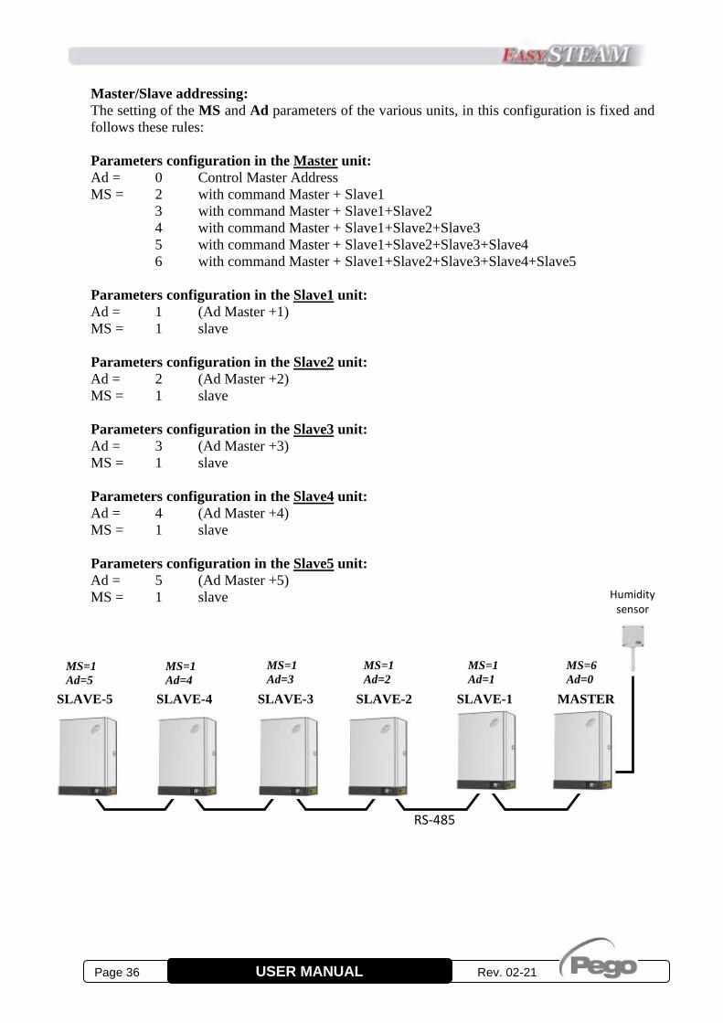
Master/Slave addressing:
The setting of the MS and Ad parameters of the various units, in this configuration is fixed and
follows these rules:
Parameters configuration in the Master unit:
Ad = 0 Control Master Address
MS = 2 with command Master + Slave1
3 with command Master + Slave1+Slave2
4 with command Master + Slave1+Slave2+Slave3
5 with command Master + Slave1+Slave2+Slave3+Slave4
6 with command Master + Slave1+Slave2+Slave3+Slave4+Slave5
Parameters configuration in the Slave1 unit:
Ad = 1 (Ad Master +1)
MS = 1 slave
Parameters configuration in the Slave2 unit:
Ad = 2 (Ad Master +2)
MS = 1 slave
Parameters configuration in the Slave3 unit:
Ad = 3 (Ad Master +3)
MS = 1 slave
Parameters configuration in the Slave4 unit:
Ad = 4 (Ad Master +4)
MS = 1 slave
Parameters configuration in the Slave5 unit:
Ad = 5 (Ad Master +5)
MS = 1 slave
MASTER
MS=1
Ad=3
MS=1
Ad=2
MS=1
Ad=1
Humidity sensor
MS=6
Ad=0
SLAVE-1 SLAVE-2 SLAVE-3
RS-485
MS=1
Ad=4
SLAVE-4
MS=1
Ad=5
SLAVE-5

Rev. 02-21 Page 37 USER MANUAL
Description of operation:
The unit configured as Master constantly communicates with the connected slaves through the RS-
485 connection, indicating the quantity of steam to be produced (0-100%) and managing the
priorities of the various units in relation to discharges for deconcentration or testing.
The operating mode of the Master/Slave unit is only set on the Master by means of the variable S9,
as well as the possible connection of the ambient humidity probe, the humidity probe in the duct,
the 0-10V reference signal, the ON-OFF enablement and the humidity setting.
The variable Pr, which represents the percentage of steam production at full capacity, is instead set
on each individual unit.
The absence of consent (clamps 24 and 25 open on Master HUM2 board) behaves as follows:
- On the Master unit, it stops the same Master unit and all the connected slave units (flashing
OFF).
- On the Slave units, stop only the slave unit concerned (OFF flashing).
Stand-by by means of the dedicated key behaves as follows:
- If activated on the Master unit, it puts the machine in stand-by mode (LED flashes on the
stand-by key) and brings the steam production request of the connected slaves to zero.
- On the Slave units, it stops only the concerned slave unit by putting the machine in stand-by
mode (LED flashes on the stand-by key).
If the Master cannot communicate with a slave, after a 15-second timeout time it signals the
problem with an alarm that can be silenced (E7). The interrogation of the slave continues and if the
communication resumes, the error is reset automatically.
If a Slave is not queried by the Master within a timeout period of 15 seconds, it considers
interrupted the connection and therefore leads to 0 the production of steam, disconnecting the
electrodes and signalling the anomaly with an alarm that can be silenced (E7). If the connection is
resumed, the alarm is reset automatically and normal operation is resumed.
On the humidifiers configured as Slaves (mS = 1), the variable S9 is not taken into account; for
them the production of steam follows in a proportional way the data sent by the Master on the
RS485 connection.
Management of priorities of discharges for deconcentration and tests:
The priorities for deconcentration discharges and for diagnostic tests are managed as follows:
The Slave units, when interrogated, send the eventual water discharge request to the Master that
manages them with a FIFO (first input / first output).
The Master waits 3 minutes before giving the next consent to the waiting unit, following the priority
in the FIFO; this allows the unit that is discharging the water to resume steam production.
The Slave unit that requested a discharge waits for the consent from the Master for 45 minutes, after
which it is executed anyway (Time out).

Page 38 Rev. 02-21 USER MANUAL
FIRST IGNITION
1. Verify that the default setting is compatible with the signal connection made; if different, configure the
electronics correctly before powering up as described in chapter 2.
2. Before connecting the humidifier, check the correct connection of the phases and of the type of input
signals; check also the correct connection of the mains water, the water drain and the steam tube.
If the mains water connection line has been made with pipes that may contain oily residues or
other substances that generate foam, it is essential to wash it by letting the water run for a few
minutes.
3. Check that there are no water leaks inside the humidifier.
4. Give power supply to the humidifier.
5. The humidifier will run a water drain for a few seconds, emitting a long beep.
6. The humidifier is now in STAND-BY mode. To switch it on, press the ON/OFF – STAND-BY key: the
humidifier will display the humidity or temperature or current absorption value, according to the set
operating mode.
7. The humidifier to work requires the digital input 1 to be enabled by means of a voltage free contact
(terminals 24 and 25 on the electronic board Master HUM2) regardless of the selected operating mode
and if the parameter In1 = ± 2. When not enabled, the display alternates the word OFF to the normal
display.
STEAM PRODUCTION
1. Set the required humidity or temperature value by pressing the SET key and increasing the value with
the UP key, in the 4-20mA PROPORTIONAL models (if the set value is higher than that measured by
the probe, steam production begins); or give ON/OFF or 0-10V consent in the ON/OFF or
PROPORTIONAL 0-10V models.
2. Allow the cylinder to fill up until the water starts boiling, then completely empty the cylinder with the
MANUAL DRAIN key to start the pump. Repeat the operation 1-2 times.
3. Now the humidifier is operational and can function properly in a completely autonomous way.
SMART PRODUCTION FOR LOW CONDUCTIVITY
Smart production function with low conductivity water.
Set parameter S11=1 if all the following conditions are true:
- the requested percentage of steam production Pr was not reached;
- at start-up, the cylinder fills up completely and triggers the level sensor;
- the current measured with a cylinder full of water is greater than 0.5A, but it is not sufficient to
guarantee the required steam production.
With the "Smart production for low conductivity" function activated, the humidifier automatically regulates
the percentage of steam production based on the conductivity of the water. If the water is not sufficiently
conductive at the first start, the percentage of steam production is reduced to avoid reaching the level sensor
and the consequent blocking of the machine. The humidifier will not work immediately according to the
steam production percentage set with parameter Pr, but the purpose of the procedure is to reach it
gradually. When the function is active, the value of the calculated steam request can be displayed in the PrL
parameter (first level of programming).
The Smart production for low conductivity function only modifies the percentage of steam production. In the
case of water with extremely low conductivity, it is advisable to modify the following parameters:
S2 Deconcentration discharging interval: set 30 ÷ 50 min
S4 Discharge of water for inactivity: set 0
S8 Set = 0 to activate step water loading.
CHAP. 5 IGNITING THE HUMIDIFIER
5.1
5.2
5.3

Rev. 02-21 Page 39 USER MANUAL
The EASYSTEAM humidifier in case of anomalies warns the operator through alarm codes and visual and
acoustic signalling.
When an alarm condition occurs, the display icon is activated, the alarm relay is activated (if configured), the
internal buzzer is activated and one of the following alarm codes is displayed.
At any time, by pressing the "silence" key it is possible to inhibit the internal buzzer. Pressing the SET key
resets the acoustic signalling.
Alarms can be of three types, depending on their severity:
- With automatic reset (the alarm is reset automatically when the problem disappears).
- With manual reset from keyboard (the alarm is reset automatically).
- With manual reset by removing power supply to the board (serious alarm that cannot be silenced).
Without the console it is possible to identify the type of alarm present by counting the flashes of the red LED
on the Master (e.g. for E3 there are 3 flashes followed by a long pause. Instead, the E0 alarm is signalled
with the permanent lighting of the red LED on the Master).
To reset an alarm without automatic reset, in the absence of the display, switch off the power supply to the
electronics. The Do4 output (clamps 7 and 8) is set by default as an alarm relay (second level variable
dO4=1).
CODE POSSIBLE CAUSE/DESCRIPTION OPERATION TO BE PERFORMED RESET
OFF flashing
The enabling consent is absent
On the Master HUM2 check the enabling consent
on clamps 24 and 25 and the configuration of
eventual additional consents of the digital inputs.
automatic
flashing
without any
alarm code
Maximum water level in the cylinder.
The water inside the cylinder has reached the
maximum level sensor and the absorbed current is
within a permitted range (> 0.5A).
(during this alarm there is no acoustic signalling)
At the beginning of a steam production cycle, if the
water inside the cylinder reaches the maximum level
sensor, the cylinder is emptied completely to try to
eliminate the presence of foam (anti-foam cycle) and
then starts again with steam production. After the
anti-foam cycle, if the level is still reached, the water
load is blocked and steam continues to be produced.
Particles in suspension produced by oils or
greases present in the water loading line may
cause foaming that activates the level sensor:
perform some complete washes of the cylinder
with manual water discharge, immediately after
the full load.
A water conductivity above 1300S/cm may
cause foaming: increase the frequency of
deconcentration discharges by modifying
parameter S2.
Check that there is no water under the cable-
carrier circular tube, on the top of the cylinder.
This, if present, could penetrate the circular tube
and create a false contact on the level sensor: dry
everything carefully.
automatic
permanent
without any
alarm code
Permanence of the maximum level of water in the
cylinder.
The maximum water level sensor in the cylinder has
been activated continuously for more than one hour,
after an anti-foam cycle.
This alarm blocks the production of steam until it is
acquired (pressing the Silence key).
Use the same operations as indicated for the
"Maximum water level in the cylinder". manual
En No connection between the NANO EasySTEAM
display and the Master HUM2 electronics
Check connection on J1 connector and of
connection cable. automatic
EE EEPROM ALARM
An error has been detected in the EEPROM memory
(the outputs are all disabled, except for alarms)
• Switch the appliance off and on again.
• If the problem persists, contact the technical
assistance service.
manual
CHAP. 6 DIAGNOSTICS

Page 40 Rev. 02-21 USER MANUAL
E0
Functional anomaly of the ambient probe, set in
the variable S9.
Verify the correct configuration of the used probe
(variable S9 and electrical connections on
dedicated clamps).
If the problem persists, replace the probe.
automatic
E1
Maximum level of water in the cylinder /
Problems of current reading.
The water inside the cylinder has reached the
maximum level sensor and the absorbed current is
below the minimum threshold of 0.5A.
The achievement of the maximum level combined
with a current measured too low, identifies an
anomaly that does not occur in normal operation.
This alarm blocks the production of steam until it is
acquired (pressing the Silence key).
Check the correct insertion of the cylinder
connector to the humidifier.
Using an amperometric clamp, check the
absorption on the supply phases: one of the
phases may be interrupted.
Check the deterioration of the cylinder electrodes.
Check that the conductivity of the water is above
the minimum allowed for the type of cylinder
used; in particular, for normal cylinders it must be
greater than 250S/cm and for cylinders with low
conductivity it must be greater than 125S/cm. If
so, try reducing the steam production % by
modifying the Pr variable to lower the water
working level in the cylinder.
Particles in suspension produced by oils or
greases present in the water loading line may
cause foaming that activates the level sensor:
perform some complete washes of the cylinder
with manual water discharge, immediately after
the full load.
A water conductivity above 1300S/cm may
cause foaming: increase the frequency of
deconcentration discharges by modifying
parameter S2.
Check that there is no water under the circular
cable tray, on the top of the cylinder. This, if
present, could penetrate the circular cable tray
and create a false contact on the level sensor: dry
everything carefully.
manual
E1
+
flashing
Pump discharge test anomaly
(Skipped 5 consecutive tests).
During a pump discharge test (performed once every
10 hours of operation) if the maximum level is
reached or the test current It isn't reached within 10
minutes, the test is interrupted and considered
SKIPPED.
After the consecutive skip of 5 tests the error E1 is
activated and the steam production is blocked until
the alarm is acquired (pressing the Silence key).
Use the same operations as indicated for the E1
error described above. manual
E2 Functional anomaly of the humidity probe in air
duct, set in variable S9.
Verify the correct configuration of the used probe
(variable S9 and electrical connections on
dedicated clamps).
If the problem persists, replace the probe.
automatic
E3
Lack of water for a prolonged time.
When S2>=10 and the water loading solenoid valve
remains active for a time equal to (S2 minus 1
minute), the alarm E3 is activated.
If S2 < 10 the alarm E3 is deactivated.
This alarm blocks steam production.
To reset the alarm, you need to enter and exit the
stand-by.
Check that the mains water line is active.
Verify that there is no water leak due to a break.
Verify that the water loading solenoid valve is not
faulty or disconnected.
manual
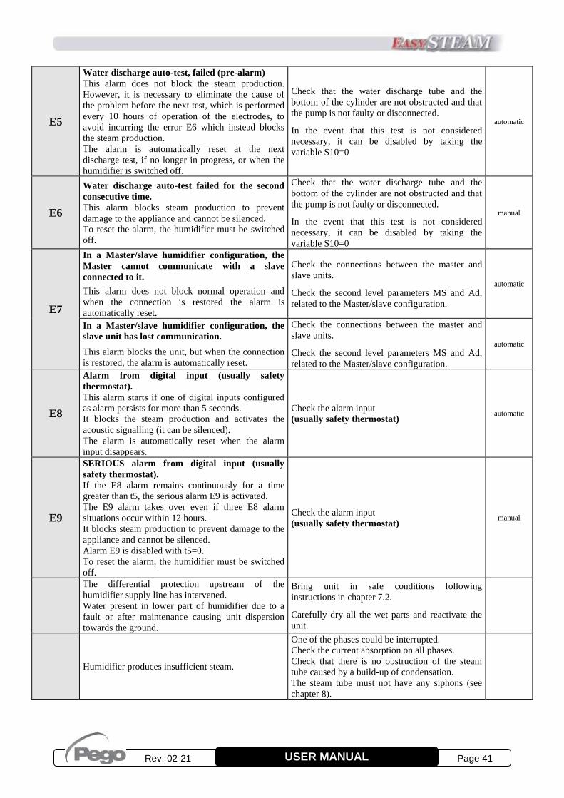
Rev. 02-21 Page 41 USER MANUAL
E5
Water discharge auto-test, failed (pre-alarm)
This alarm does not block the steam production.
However, it is necessary to eliminate the cause of
the problem before the next test, which is performed
every 10 hours of operation of the electrodes, to
avoid incurring the error E6 which instead blocks
the steam production.
The alarm is automatically reset at the next
discharge test, if no longer in progress, or when the
humidifier is switched off.
Check that the water discharge tube and the
bottom of the cylinder are not obstructed and that
the pump is not faulty or disconnected.
In the event that this test is not considered
necessary, it can be disabled by taking the
variable S10=0
automatic
E6
Water discharge auto-test failed for the second
consecutive time.
This alarm blocks steam production to prevent
damage to the appliance and cannot be silenced.
To reset the alarm, the humidifier must be switched
off.
Check that the water discharge tube and the
bottom of the cylinder are not obstructed and that
the pump is not faulty or disconnected.
In the event that this test is not considered
necessary, it can be disabled by taking the
variable S10=0
manual
E7
In a Master/slave humidifier configuration, the
Master cannot communicate with a slave
connected to it.
This alarm does not block normal operation and
when the connection is restored the alarm is
automatically reset.
Check the connections between the master and
slave units.
Check the second level parameters MS and Ad,
related to the Master/slave configuration.
automatic
In a Master/slave humidifier configuration, the
slave unit has lost communication.
This alarm blocks the unit, but when the connection
is restored, the alarm is automatically reset.
Check the connections between the master and
slave units.
Check the second level parameters MS and Ad,
related to the Master/slave configuration.
automatic
E8
Alarm from digital input (usually safety
thermostat).
This alarm starts if one of digital inputs configured
as alarm persists for more than 5 seconds.
It blocks the steam production and activates the
acoustic signalling (it can be silenced).
The alarm is automatically reset when the alarm
input disappears.
Check the alarm input
(usually safety thermostat) automatic
E9
SERIOUS alarm from digital input (usually
safety thermostat).
If the E8 alarm remains continuously for a time
greater than t5, the serious alarm E9 is activated.
The E9 alarm takes over even if three E8 alarm
situations occur within 12 hours.
It blocks steam production to prevent damage to the
appliance and cannot be silenced.
Alarm E9 is disabled with t5=0.
To reset the alarm, the humidifier must be switched
off.
Check the alarm input
(usually safety thermostat) manual
The differential protection upstream of the
humidifier supply line has intervened.
Water present in lower part of humidifier due to a
fault or after maintenance causing unit dispersion
towards the ground.
Bring unit in safe conditions following
instructions in chapter 7.2.
Carefully dry all the wet parts and reactivate the
unit.
Humidifier produces insufficient steam.
One of the phases could be interrupted.
Check the current absorption on all phases.
Check that there is no obstruction of the steam
tube caused by a build-up of condensation.
The steam tube must not have any siphons (see
chapter 8).
Page 42 Rev. 02-21 USER MANUAL
MAINTENANCE
To guarantee operational safety, correct operation and optimal performance of the EASYSTEAM
series humidifiers, regular maintenance must be carried out according to the instructions below.
GENERAL AND SAFETY STANDARDS
Whatever the type of maintenance, it must only be carried out by expert and qualified
technical personnel, aware of the necessary safety precautions.
Before starting any maintenance operation, proceed as follows:
1. If the unit is out of service for an alarm condition, make a note of the error code shown on the
display.
2. Close the shut-off valve on the water supply line.
3. Bring the humidifier into stand-by, using the appropriate key, and completely drain the water
contained in the cylinder by pressing the manual drain key on the front of the NANO Display
(see chapter 3).
4. Disconnect the unit from the mains, using the upstream power switch and padlocking it to OFF.
5. Wait until the cylinder and the humidifier have cooled down or use protective gloves.
6. Each item of the appliance, in case it should be faulty or damaged, must be replaced only with
original parts.
MAINTENANCE INTERVALS
The following are the maintenance operations to be performed and their suggested frequency.
However, since the consumption of the electrodes and the formation of limescale and solid deposits
inside the cylinder vary according to the type of water (even with the same conductivity), more
frequent maintenance may be necessary.
Check this need by checking the amount of deposits inside the cylinder: a fast accumulation of
limescale and deposits requires an increase in the suggested maintenance frequency and/or the
variation of the parameters related to the deconcentration discharges.
To minimize the formation of deposits on the bottom of the cylinder it is advisable to
increase the frequency of deconcentration discharges, reducing the value of the S2
variable. However, this measure has the disadvantage of determining a greater
consumption of water and energy.
CHAP. 7 MAINTENANCE
7.1
7.2
7.3

Rev. 02-21 Page 43 USER MANUAL
MAINTENANCE OPERATIONS TO BE PERFORMED FREQUENCY
Check the absence of water leaks inside the humidifier. After 1 hour of functioning
Check the tightening of the electrical connections. After 4 weeks of
functioning
Check the absence of water leaks inside the humidifier.
Check the condition of the cylinder and remove any deposits or
limescale if present inside.
Replace the cylinder, if necessary.
Monthly or every 500
hours of functioning
Check the wear of the cylinder electrodes and the absence of
deformations or blackening on their surface; replace the cylinder in
case of wear or obvious defects.
Every three months or
every 1000 hours of
functioning
Replace the cylinder.
Check the tightening of the electrical connections and the good
condition of water and steam connections.
Annually or every 2500
hours of functioning
Check for water leaks inside the humidifier.
Check cylinder status: check the wear of the electrodes and remove
any deposits or limescale if present inside.
Replace the cylinder, if necessary.
When the E1 alarm code
occurs
Check the absence of water leaks inside the humidifier.
Verify that the water loading solenoid valve is not disconnected or
faulty; if so, replace it.
When the E3 alarm code
occurs
Verify that the discharge pump is not disconnected or faulty: if so,
replace it.
If present, eliminate any blockages on the bottom of the cylinder and
in the water discharge tube.
When the E5 or E6 alarm
code occurs
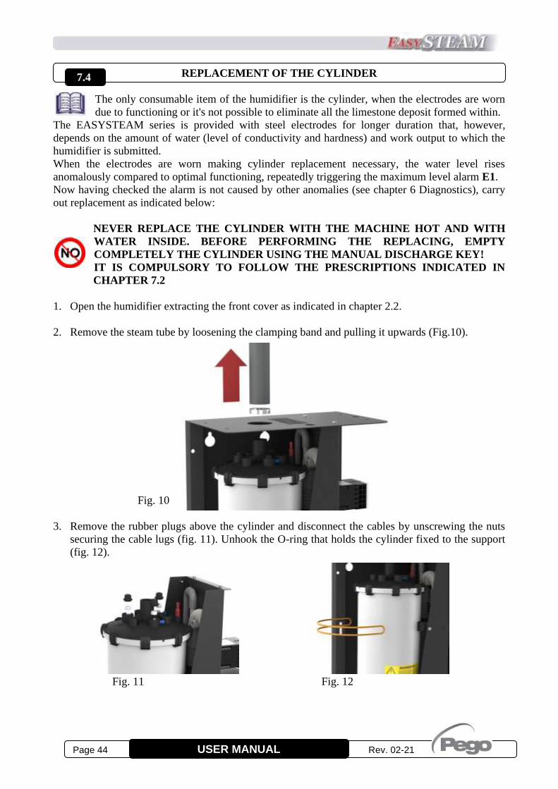
Page 44 Rev. 02-21 USER MANUAL
REPLACEMENT OF THE CYLINDER
The only consumable item of the humidifier is the cylinder, when the electrodes are worn
due to functioning or it's not possible to eliminate all the limestone deposit formed within. The EASYSTEAM series is provided with steel electrodes for longer duration that, however,
depends on the amount of water (level of conductivity and hardness) and work output to which the
humidifier is submitted.
When the electrodes are worn making cylinder replacement necessary, the water level rises
anomalously compared to optimal functioning, repeatedly triggering the maximum level alarm E1.
Now having checked the alarm is not caused by other anomalies (see chapter 6 Diagnostics), carry
out replacement as indicated below:
NEVER REPLACE THE CYLINDER WITH THE MACHINE HOT AND WITH
WATER INSIDE. BEFORE PERFORMING THE REPLACING, EMPTY
COMPLETELY THE CYLINDER USING THE MANUAL DISCHARGE KEY!
IT IS COMPULSORY TO FOLLOW THE PRESCRIPTIONS INDICATED IN
CHAPTER 7.2
1. Open the humidifier extracting the front cover as indicated in chapter 2.2.
2. Remove the steam tube by loosening the clamping band and pulling it upwards (Fig.10).
Fig. 10
3. Remove the rubber plugs above the cylinder and disconnect the cables by unscrewing the nuts
securing the cable lugs (fig. 11). Unhook the O-ring that holds the cylinder fixed to the support
(fig. 12).
Fig. 11 Fig. 12
7.4

Rev. 02-21 Page 45 USER MANUAL
4. Remove the cylinder from the lower flange extracting it upwards (Fig. 13) and remove it from
the humidifier (fig. 14).
Fig. 13 Fig. 14
5. Carefully clean the seat where the new cylinder will be inserted, checking the integrity of the
O-ring inside the seat and that there are no pieces of limestone that could compromise the seal.
6. Insert the new cylinder by repeating the operations for removal in reverse. To facilitate
insertion, moisten the lower part of the cylinder with water or grease it with technical vaseline
oil.
7. Make the electrical connections as shown below (fig. 15):
CODE M2-L1 U V L2-M1 W U-M2 L3 V M1 W
400UMCLCCU02 PHASE / NEUTRAL PHASE / NEUTRAL
400UMCLCCU01 PHASE 1 / PHASE 2 / PHASE 3 /
400UMCLCCU03 PHASE 1 PHASE 3 PHASE 2 PHASE 1 PHASE 3 PHASE 2
Connect the level sensor to the WL connector.
8. Perform two or three complete washes of the cylinder
immediately after replacement by pressing the “manual
discharge key".
9. Check the absence of water leaks inside the humidifier after
one hour of operation from cylinder replacement.
DO NOT USE GREASE OR OILS NOT SUPPLIED IN THE PACKAGE FOR INSERTION OF THE CYLINDER. PERFORM TWO OR THREE COMPLETE WASHES OF THE CYLINDER IMMEDIATELY AFTER REPLACEMENT BY PRESSING THE “MANUAL DISCHARGE KEY".
Fig. 15
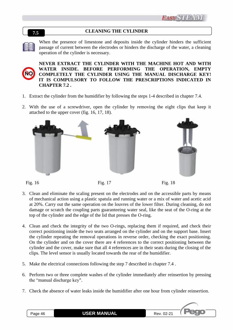
Page 46 Rev. 02-21 USER MANUAL
CLEANING THE CYLINDER
When the presence of limestone and deposits inside the cylinder hinders the sufficient
passage of current between the electrodes or hinders the discharge of the water, a cleaning
operation of the cylinder is necessary.
NEVER EXTRACT THE CYLINDER WITH THE MACHINE HOT AND WITH
WATER INSIDE. BEFORE PERFORMING THE OPERATION, EMPTY
COMPLETELY THE CYLINDER USING THE MANUAL DISCHARGE KEY!
IT IS COMPULSORY TO FOLLOW THE PRESCRIPTIONS INDICATED IN
CHAPTER 7.2 .
1. Extract the cylinder from the humidifier by following the steps 1-4 described in chapter 7.4.
2. With the use of a screwdriver, open the cylinder by removing the eight clips that keep it
attached to the upper cover (fig. 16, 17, 18).
Fig. 16 Fig. 17 Fig. 18
3. Clean and eliminate the scaling present on the electrodes and on the accessible parts by means
of mechanical action using a plastic spatula and running water or a mix of water and acetic acid
at 20%. Carry out the same operation on the louvres of the lower filter. During cleaning, do not
damage or scratch the coupling parts guaranteeing water seal, like the seat of the O-ring at the
top of the cylinder and the edge of the lid that presses the O-ring.
4. Clean and check the integrity of the two O-rings, replacing them if required, and check their
correct positioning inside the two seats arranged on the cylinder and on the support base. Insert
the cylinder repeating the removal operations in reverse order, checking the exact positioning.
On the cylinder and on the cover there are 4 references to the correct positioning between the
cylinder and the cover, make sure that all 4 references are in their seats during the closing of the
clips. The level sensor is usually located towards the rear of the humidifier.
5. Make the electrical connections following the step 7 described in chapter 7.4 .
6. Perform two or three complete washes of the cylinder immediately after reinsertion by pressing
the “manual discharge key".
7. Check the absence of water leaks inside the humidifier after one hour from cylinder reinsertion.
7.5
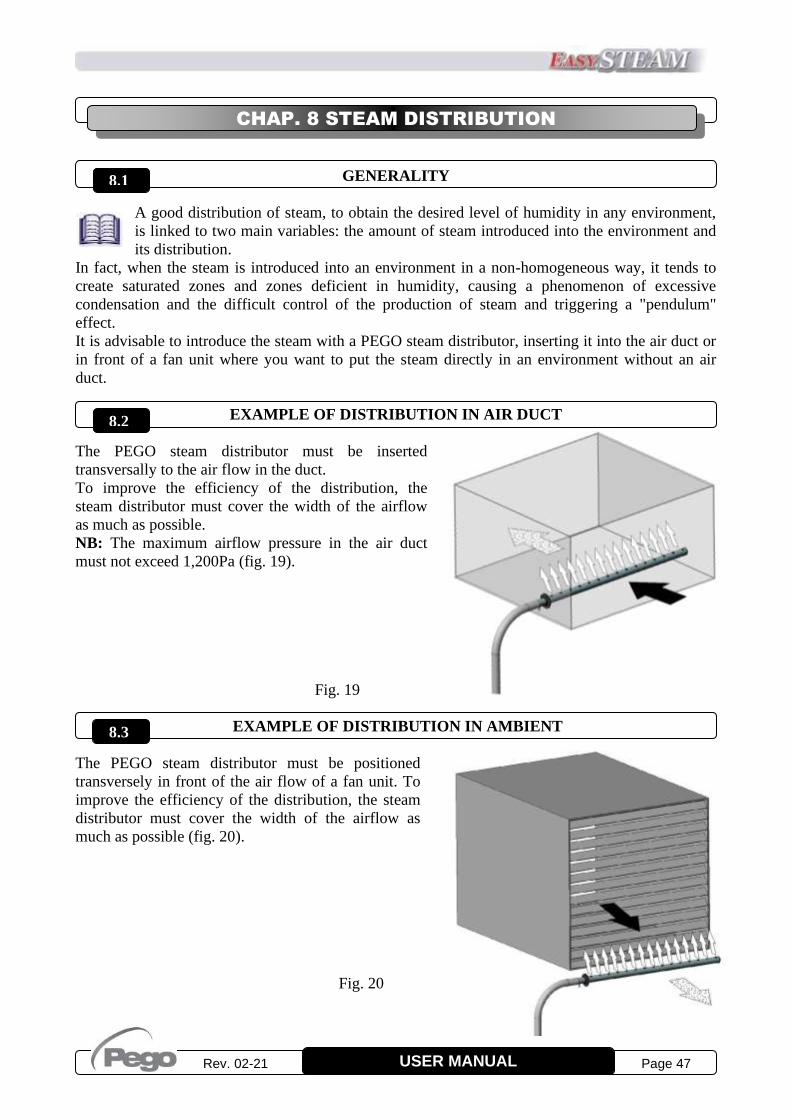
Rev. 02-21 Page 47 USER MANUAL
GENERALITY
A good distribution of steam, to obtain the desired level of humidity in any environment,
is linked to two main variables: the amount of steam introduced into the environment and
its distribution.
In fact, when the steam is introduced into an environment in a non-homogeneous way, it tends to
create saturated zones and zones deficient in humidity, causing a phenomenon of excessive
condensation and the difficult control of the production of steam and triggering a "pendulum"
effect.
It is advisable to introduce the steam with a PEGO steam distributor, inserting it into the air duct or
in front of a fan unit where you want to put the steam directly in an environment without an air
duct.
EXAMPLE OF DISTRIBUTION IN AIR DUCT
The PEGO steam distributor must be inserted
transversally to the air flow in the duct.
To improve the efficiency of the distribution, the
steam distributor must cover the width of the airflow
as much as possible.
NB: The maximum airflow pressure in the air duct
must not exceed 1,200Pa (fig. 19).
Fig. 19
EXAMPLE OF DISTRIBUTION IN AMBIENT
The PEGO steam distributor must be positioned
transversely in front of the air flow of a fan unit. To
improve the efficiency of the distribution, the steam
distributor must cover the width of the airflow as
much as possible (fig. 20).
Fig. 20
CHAP. 8 STEAM DISTRIBUTION
8.2
8.1
8.3
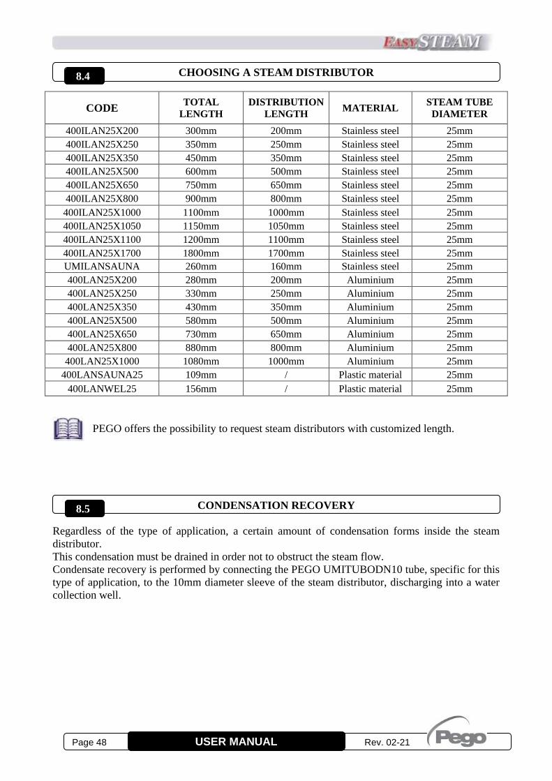
Page 48 Rev. 02-21 USER MANUAL
CHOOSING A STEAM DISTRIBUTOR
CODE TOTAL
LENGTH
DISTRIBUTION
LENGTH MATERIAL
STEAM TUBE
DIAMETER
400ILAN25X200 300mm 200mm Stainless steel 25mm
400ILAN25X250 350mm 250mm Stainless steel 25mm
400ILAN25X350 450mm 350mm Stainless steel 25mm
400ILAN25X500 600mm 500mm Stainless steel 25mm
400ILAN25X650 750mm 650mm Stainless steel 25mm
400ILAN25X800 900mm 800mm Stainless steel 25mm
400ILAN25X1000 1100mm 1000mm Stainless steel 25mm
400ILAN25X1050 1150mm 1050mm Stainless steel 25mm
400ILAN25X1100 1200mm 1100mm Stainless steel 25mm
400ILAN25X1700 1800mm 1700mm Stainless steel 25mm
UMILANSAUNA 260mm 160mm Stainless steel 25mm
400LAN25X200 280mm 200mm Aluminium 25mm
400LAN25X250 330mm 250mm Aluminium 25mm
400LAN25X350 430mm 350mm Aluminium 25mm
400LAN25X500 580mm 500mm Aluminium 25mm
400LAN25X650 730mm 650mm Aluminium 25mm
400LAN25X800 880mm 800mm Aluminium 25mm
400LAN25X1000 1080mm 1000mm Aluminium 25mm
400LANSAUNA25 109mm / Plastic material 25mm
400LANWEL25 156mm / Plastic material 25mm
PEGO offers the possibility to request steam distributors with customized length.
CONDENSATION RECOVERY
Regardless of the type of application, a certain amount of condensation forms inside the steam
distributor.
This condensation must be drained in order not to obstruct the steam flow.
Condensate recovery is performed by connecting the PEGO UMITUBODN10 tube, specific for this
type of application, to the 10mm diameter sleeve of the steam distributor, discharging into a water
collection well.
8.4
8.5
Rev. 02-21 Page 49 USER MANUAL
EU DECLARATION OF CONFORMITY
LA PRESENTE DICHIARAZIONE DI CONFORMITA’ E’ RILASCIATA SOTTO LA RESPONSABILITA’ ESCLUSIVA DEL FABBRICANTE: THIS DECLARATION OF CONFORMITY IS ISSUED UNDER THE EXCLUSIVE RESPONSIBILITY OF THE MANUFACTURER:
PEGO S.r.l. a socio unico - Via Piacentina 6/b, 45030 Occhiobello (RO) – Italy –
Società soggetta all’attività di direzione e coordinamento di Castel S.r.l.
DENOMINAZIONE DEL PRODOTTO IN OGGETTO / DENOMINATION OF THE PRODUCT IN OBJECT
MOD.: 400ES3MMINI
MOD.: 400ES6MINI
IL PRODOTTO DI CUI SOPRA E’ CONFORME ALLA PERTINENTE NORMATIVA DI ARMONIZZAZIONE
DELL’UNIONE EUROPEA:
THE PRODUCT IS IN CONFORMITY WITH THE RELEVANT EUROPEAN HARMONIZATION LEGISLATION:
Direttiva Bassa Tensione (LVD): 2014/35/UE
Low voltage directive (LVD): 2014/35/EU
Direttiva EMC: 2014/30/UE
Electromagnetic compatibility (EMC): 2014/30/EU
LA CONFORMITA’ PRESCRITTA DALLA DIRETTIVA E’ GARANTITA DALL’ADEMPIMENTO A TUTTI GLI EFFETTI DELLE SEGUENTI NORME: THE CONFORMITY REQUIRED BY THE DIRECTIVE IS GUARANTEED BY THE FULFILLMENT TO THE FOLLOWING STANDARDS:
Norme armonizzate:
European standards:
EN 60335-1:2012, EN 60335-2-98:2003, EN 55014-1:2006, EN 55014-2:2015, EN61000-3-2:2014,
EN 61000-3-3:2013, EN 61000-3-11:2000, EN 61000-3-12:2011, EN 61000-6-1:2007, EN 61000-6-2 :2005,
EN 61000-6-3:2007, EN 61000-6-4:2007.
IL PRODOTTO E’ COSTITUITO PER ESSERE INCORPORATO IN UNA MACCHINA O PER ESSERE ASSEMBLATO CON ALTRI MACCHINARI PER COSTITUIRE UNA MACCHINA CONSIDERATE DALLA DIRETTIVA: 2006/42/CE “Direttiva Macchine”. THE PRODUCT HAS BEEN MANUFACTURED TO BE INCLUDED IN A MACHINE OR TO BE ASSEMBLED TOGHETER WITH OTHER MACHINERY TO COMPLETE A MACHINE ACCORDING TO DIRECTIVE: EC/2006/42 “Machinery Directive”. Firmato per nome e per conto di: Signed for and on behalf of:
CHAP. 9 ATTACHMENTS
9.1
Luogo e Data del rilascio:
Place and Date of Release:
Occhiobello (RO), 01/01/2020
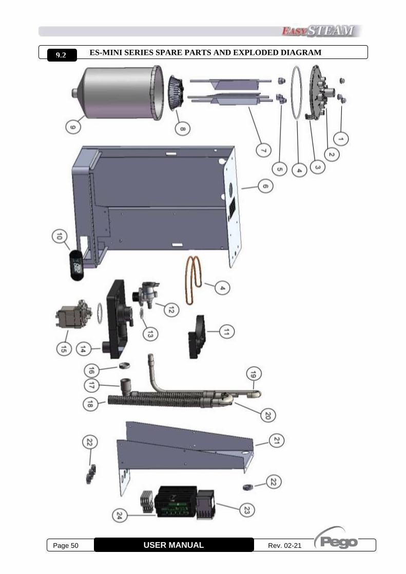
Page 50 Rev. 02-21 USER MANUAL
ES-MINI SERIES SPARE PARTS AND EXPLODED DIAGRAM
9.2

Rev. 02-21 Page 51 USER MANUAL
ES-MINI SERIES SPARE PARTS LIST
Ref. Code Description
1 UMISTHT12 Wheel nut cap
2 UMICOCCU ES-MINI/CCU cylinder cover
3 UMIGANCCU ES-MINI/CCU cylinders fixing hook
4 UMIOR7 O-ring for cylinder cover
5+7+8
400UMEL01
400UMEL02
400UMEL03
Three-phase electrodes and anti-scale filter replacement kit for ES-MINI/CCU
cylinders.
Monophase electrodes and anti-scale filter replacement kit for ES-MINI/CCU cylinders.
Electrodes and anti-scale filter replacement kit for low conductivity ES-MINI/CCU
cylinders.
6 - ES-MINI supporting structure
1+2+3+
4+5+7+
8+9+13
400UMCLCCU02
400UMCLCCU01
400UMCLCCU03
Cylinder with capacity 3kg/h, electrodes, anti-scale filter and O-rings replacement kit.
Cylinder with capacity 6kg/h, electrodes, anti-scale filter and O-rings replacement kit.
Cylinder for low conductivity, with capacity 6kg/h, electrodes, anti-scale filter and
O-rings replacement kit.
10 400HUMESDIS Display NANO EasySTEAM series
11 - ES-MINI/CCU Cylinder Bracket
12 400UMIVALV Water inlet solenoid 230V 50-60 Hz ES-MINI/CCU
13 UMIOR5 O-ring for cylinder base
14 - Base support in PP for ES-MINI/CCU
15 400UMPO25-150 Asynchronous drain pump 230V 50Hz (60Hz version available on request)
16+17+
18+20 400UMSIF07 Complete siphon replacement kit + water drain pump for ES-MINI/CCU
19 UMITUBO10-8 ES-MINI/CCU water inlet pipe
21 - Steel support electronic ES-MINI/CCU
22 - Grommet with membrane
23 CON20161AP01 Power contactor, electrode power supply ES-MINI
24 400HUM2ES3M
400HUM2ES6
Master HUM2 electronic control for ES3-MINI
Master HUM2 electronic control for ES6-MINI
10+24 400KHUM2ES3M
400KHUM2ES6
Master HUM2 electronic control kit + NANO Display for ES3-MINI
Master HUM2 electronic control kit + NANO Display for ES6-MINI
The spare parts must be requested from own dealer.

Page 52 Rev. 02-21 USER MANUAL
PEGO s.r.l.
Via Piacentina, 6/b 45030 Occhiobello ROVIGO – ITALY
Tel. +39 0425 762906
e-mail: [email protected] – www.pego.it
AFTER-SALES ASSISTANCE
Tel. +39 0425 762906 e-mail: [email protected]
Distributor:
PEGO s.r.l. reserves the right to make amendments to this user manual at any moment.