
Humidifiers - · PDF fileSTEAM INJECTION Humidifiers Installation, Operation, and Maintenance...
64
STEAM INJECTION Humidifiers Installation, Operation, and Maintenance Manual READ AND SAVE THESE INSTRUCTIONS For use with steam boilers
Transcript of Humidifiers - · PDF fileSTEAM INJECTION Humidifiers Installation, Operation, and Maintenance...

STEAM INJECTION
Humidif iers
Installation, Operation, and Maintenance Manual
READ AND SAVE THESE INSTRUCTIONS
For use with steam boilers
ii STEAM INJECTION INSTALLATION, OPERATION, AND MAINTENANCE MANUAL
Safety precautions
ATTENTION INSTALLER Read this manual before installing. Leave manual with product owner.
Where to find more informationOn our website:The following related documents can be viewed, printed, or ordered from our website, www.dristeem.com
In Dri-calc®
Dri-calc is DriSteem’s free sizing and selection software for calculating load, determining non-wetting distance, and selecting equipment. See Dri-calc on the www.dristeem.com Tools page. Also in Dri-calc: A comprehensive library of Installation Guide documents, including: • Recommendedplacementwithinaduct
or air handler
• Recommendedsensorplacement
Or call us at 800-328-4447Obtaining documents from our website or from Dri-calc is the quickest way to view our literature, or we will be happy to mail literature to you.
WARNING Indicates a hazardous situation that could result in death or serious injury if instructions are not followed.
WARNINGAttention installerRead this manual before installing, and leave this manual with product owner. This product must be installed by qualified HVAC and electrical contractors and in compliance with local, state, federal, and governing codes. Improper installation can cause property damage, severe personal injury, or death as a result of electric shock, burns, or fire.
DriSteem® technical support: 800-328-4447
Read all warnings and instructionsRead this manual before performing service or maintenance procedures on any part of the system. Failure to follow all warnings and instructions could produce the hazardous situations described, resulting in property damage, personal injury, or death.
Failure to follow the instructions in this manual can cause moisture to accumulate, which can cause bacteria and mold growth or dripping water into building spaces. Dripping water can cause property damage; bacteria and mold growth can cause illness.mc_011909_1215
Hot surfaces and hot waterSteam Injection humidifiers have extremely hot surfaces. Water in steam pipes and dispersion assemblies can be as hot as 212 °F (100 °C). Discharged steam is not visible. Contact with hot surfaces, discharged hot water, or air into which steam has been discharged can cause severe personal injury. To avoid severe burns, allow the system to cool before performing service or maintenance procedures on any part of the system.

1STEAM INJECTION INSTALLATION, OPERATION, AND MAINTENANCE MANUAL
Table of contents
ATTENTION INSTALLERRead this manual before installing. Leave manual with product owner.
DriSteem technical support800-328-4447
WARNINGHot surface hazardSteam humidification systems have extremely hot surfaces.
To avoid burns, allow humidifier, steam pipes, and dispersion assemblies to cool before touching any part of the system.mc_071411_0753
OVERVIEW . . . . . . . . . . . . . . . . . . . . . . . . . . . . . . . . . . . . . . . . . . . . . . . . . . . . . . . . . . . . . . . . .2Introduction . . . . . . . . . . . . . . . . . . . . . . . . . . . . . . . . . . . . . . . . . . . . . 2Available models . . . . . . . . . . . . . . . . . . . . . . . . . . . . . . . . . . . . . . . . . 3Basic components . . . . . . . . . . . . . . . . . . . . . . . . . . . . . . . . . . . . . . . . 4Principle of operation . . . . . . . . . . . . . . . . . . . . . . . . . . . . . . . . . . . . . . 5Humidifier placement . . . . . . . . . . . . . . . . . . . . . . . . . . . . . . . . . . . . . . 6Sensor placement . . . . . . . . . . . . . . . . . . . . . . . . . . . . . . . . . . . . . . . . 9Pressurized steam piping guidelines . . . . . . . . . . . . . . . . . . . . . . . . . . 10Condensate drain piping and trapping . . . . . . . . . . . . . . . . . . . . . . . . 14Temperature switches . . . . . . . . . . . . . . . . . . . . . . . . . . . . . . . . . . . . . 16
SINGLE-TUBE HUMIDIFIER . . . . . . . . . . . . . . . . . . . . . . . . . . . . . . . . . . . . . . . . . . . . . . . . . . . . 20Configurations . . . . . . . . . . . . . . . . . . . . . . . . . . . . . . . . . . . . . . . . . 20Assembly . . . . . . . . . . . . . . . . . . . . . . . . . . . . . . . . . . . . . . . . . . . . . 21Installation . . . . . . . . . . . . . . . . . . . . . . . . . . . . . . . . . . . . . . . . . . . . 22Piping notes . . . . . . . . . . . . . . . . . . . . . . . . . . . . . . . . . . . . . . . . . . . 23Field piping . . . . . . . . . . . . . . . . . . . . . . . . . . . . . . . . . . . . . . . . . . . 24
MULTIPLE-TUBE HUMIDIFIER . . . . . . . . . . . . . . . . . . . . . . . . . . . . . . . . . . . . . . . . . . . . . . . . . . 28Field assembly . . . . . . . . . . . . . . . . . . . . . . . . . . . . . . . . . . . . . . . . . 28Installation . . . . . . . . . . . . . . . . . . . . . . . . . . . . . . . . . . . . . . . . . . . . 29Piping notes . . . . . . . . . . . . . . . . . . . . . . . . . . . . . . . . . . . . . . . . . . . 30Field piping . . . . . . . . . . . . . . . . . . . . . . . . . . . . . . . . . . . . . . . . . . . 31
MAXI-BANK HUMIDIFIER . . . . . . . . . . . . . . . . . . . . . . . . . . . . . . . . . . . . . . . . . . . . . . . . . . . . 36Maxi-bank option field assembly and installation . . . . . . . . . . . . . . . . . 36Maxi-bank option piping notes . . . . . . . . . . . . . . . . . . . . . . . . . . . . . . 39Maxi-bank option field piping . . . . . . . . . . . . . . . . . . . . . . . . . . . . . . . 40Assembly and installation . . . . . . . . . . . . . . . . . . . . . . . . . . . . . . . . . . 45
MINI-BANK HUMIDIFIER . . . . . . . . . . . . . . . . . . . . . . . . . . . . . . . . . . . . . . . . . . . . . . . . . . . . . 45Field piping . . . . . . . . . . . . . . . . . . . . . . . . . . . . . . . . . . . . . . . . . . . 47
AREA-TYPE HUMIDIFIER . . . . . . . . . . . . . . . . . . . . . . . . . . . . . . . . . . . . . . . . . . . . . . . . . . . . . 48Installation . . . . . . . . . . . . . . . . . . . . . . . . . . . . . . . . . . . . . . . . . . . . 48Field piping . . . . . . . . . . . . . . . . . . . . . . . . . . . . . . . . . . . . . . . . . . . 49Rise, spread, and throw dimensions . . . . . . . . . . . . . . . . . . . . . . . . . . 50Humidifier start-up and shut-down . . . . . . . . . . . . . . . . . . . . . . . . . . . . 51
OPERATION . . . . . . . . . . . . . . . . . . . . . . . . . . . . . . . . . . . . . . . . . . . . . . . . . . . . . . . . . . . . . . 51Eliminating excess heat from steam jacketed humidifiers . . . . . . . . . . . . 52
MAINTENANCE . . . . . . . . . . . . . . . . . . . . . . . . . . . . . . . . . . . . . . . . . . . . . . . . . . . . . . . . . . . 54Maintenance procedures . . . . . . . . . . . . . . . . . . . . . . . . . . . . . . . . . . 54Troubleshooting . . . . . . . . . . . . . . . . . . . . . . . . . . . . . . . . . . . . . . . . . 55
TROUBLESHOOTING . . . . . . . . . . . . . . . . . . . . . . . . . . . . . . . . . . . . . . . . . . . . . . . . . . . . . . . . 55
REPLACEMENT PARTS . . . . . . . . . . . . . . . . . . . . . . . . . . . . . . . . . . . . . . . . . . . . . . . . . . . . . . . 58Single-tube and Multiple-tube humidifiers . . . . . . . . . . . . . . . . . . . . . . . 58Area-type humidifier . . . . . . . . . . . . . . . . . . . . . . . . . . . . . . . . . . . . . 60Mini-bank humidifier . . . . . . . . . . . . . . . . . . . . . . . . . . . . . . . . . . . . . 61
WARRANTY . . . . . . . . . . . . . . . . . . . . . . . . . . . . . . . . . . . . . . . . . . . . . . . . . . . . . . . . . . . . . . 62

2 STEAM INJECTION INSTALLATION, OPERATION, AND MAINTENANCE MANUAL
Introduction
OVERVIEW
SUITABLE FOR A WIDE RANGE OF APPLICATIONS
Steam Injection humidifiers from DriSteem® use steam from an external source, such as an in-house boiler or a district steam system. DriSteem’s Steam Injection humidifiers are adaptable to virtually any size application, and a wide variety of models accommodate a broad range of steam absorption requirements.
STEAM JACKETED DISPERSION TUBE MODELS FOR DUCTS AND AIR HANDLERS
Single-tube, Mini-bank®, and Multiple-tube humidifiers are designed for ducts and air handlers, and capable of a wide range of guaranteed non-wetting distances.
AREA-TYPE FOR OPEN SPACES
Area-type™ Steam Injection humidifiers are designed for open spaces such as warehouses and manufacturing spaces that do not have a duct system. The steam discharged from the humidifier is quietly dispersed by a fan without introducing water droplets into the air.
Each Single-tube, Mini-bank®, and Multiple-tube humidifier has the same basic components: a stainless steel separator, a steam valve, and one or more jacketed dispersion tubes.
For open spaces, boiler steam can be dispersed by the fan of an Area-type model.
FIGURE 2-1: STEAM INJECTION HUMIDIFIERS

3STEAM INJECTION INSTALLATION, OPERATION, AND MAINTENANCE MANUAL
Available models
OVERVIEW
All Steam Injection humidifiers shown here, except Area-type, are available with options for applications requiring stainless steel steam components.
SINGLE-TUBE HUMIDIFIER• Suitableforsmall-tomedium-capacitysystems,
1.5 – 525 lbs/hr (0.7 – 238 kg/h)
• Moderatetolongnon-wettingdistance
• Pre-assembledseparator/tubeassembly
mc_033111_0500
FIGURE 3-1: STEAM INJECTION HUMIDIFIER MODELS
AREA-TYPE HUMIDIFIER• Suitableformedium-capacitysystems,1.8–286
lbs/hr (0.8 – 130 kg/h)
• Usedinopenspaces
• Application-dependentnon-wettingdistances
MULTIPLE-TUBE HUMIDIFIER• Suitableforsmall-tolarge-capacitysystems,
6.5 – 3989 lbs/hr (2.3 – 1809 kg/h)
• Sizestofitsmallductsandlargeairhandlers
• Shorttomoderatenon-wettingdistance
• Fieldassembled(withinterconnectingpipingand header supplied by contractor)
• Maxi-bank™ option:
– Pre-assembled, except when either dimension is 98 inches (2490 mm) or more
– Includes 304 stainless steel header, with option for 316 stainless steel
– Includes black iron piping, with options for 304 or 316 stainless steel
MINI-BANK HUMIDIFIER• Suitableforsmall-capacitysystems,1.6–84lbs/
hr (0.7 – 38 kg/h)
• Shorttomoderatenon-wettingdistance
• Sizedforsmallducts
• Pre-engineeredandpre-assembled header/tube assembly, ready for mounting and hookup

4 STEAM INJECTION INSTALLATION, OPERATION, AND MAINTENANCE MANUAL
Basic components
OVERVIEW
1. Steam jacket A chamber that jackets the inner dispersion tube with hot steam to eliminate condensation and dripping
2. Steam separator Separates steam from condensate
3. Deflector plate Inside the steam separator, deflects condensate into a circular pattern and toward the drain
4. Multi-baffle plate Allows only steam to rise into the upper region of the separator
5. Internal drying tube Excludes any remaining condensate, allowing only dry steam to leave the separator
6. Steam valve Controls the amount of steam allowed into the dispersion tube
7. Dispersion tube Provides uniform steam dispersion across the duct width
8. Thermal-resin tubelet Unique tubelets extend into the dispersion tube center so only the hottest, driest steam is discharged into the air. These tubelets also have an exceptional ability to trap noise generated by the valve, making DriSteem’s Steam Injection humidifiers the quietest in the industry.
9. Steam trap Allows only condensate to pass to the condensate return system
See Figure 5-1 for a description of how these components operate together.
Section X-X
Section Y-Y
5
23
9
X
4
7
6
Y
1Y
X
Tube profile with insulation
8
OM-1171
CondensateSteam
OM-378
OM-376
mc_031611_0805
Steam-filled jacket
Optional PVDF insulation
Steam-discharge tubeletDispersion tube
Tube profile without insulation
FIGURE 4-1: STEAM INJECTION HUMIDIFIER COMPONENTS

5STEAM INJECTION INSTALLATION, OPERATION, AND MAINTENANCE MANUAL
Principle of operation
OVERVIEW
1. Boiler steam enters the humidifier at line pressure and flows through a chamber (jacket) surrounding an inner dispersion tube. The jacket of steam preheats the dispersion tube so that when steam enters the dispersion tube (at Step 5 below) it does not condense as it would if the tube were cold, thereby eliminating condensation and dripping.
2. After flowing through the steam jacket, steam with entrained condensate slows from entering the larger space of the separator and from hitting the perimeter deflector plate, and begins to spin and separate.
3. Separated steam rises through slots in the multi-baffle plate to the separator upper region, and enters the internal drying tube that excludes any remaining condensate, allowing only dry steam to leave the separator.
4. Separated condensate drains from the separator to the steam trap.
5. The steam valve controls the amount of steam allowed into the preheated dispersion tube. The steam valve is typically controlled in one of two ways:• Byasignalfromabuildingautomationsystem
• Byahumiditycontrollerconnectedtothesteamvalve
6. Steam is discharged uniformly through the tubelets into the airstream.
OM-1170
mc_031611_0808
1
2
3
4
5
6
About right-hand and left-hand discharge:Imagine you are standing in the duct where the Steam Injection humidifier is to be installed, with airflow blowing into your face:
• Specifythehumidifierwithright-handdischargeiftheseparator is on your right.
• Specifythehumidifierwithleft-handdischargeiftheseparator is on your left.
For consistency, humidifier drawings in this catalog are shown with right-hand discharge.
FIGURE 5-1: STEAM INJECTION HUMIDIFIER PRINCIPLE OF OPERATION

6 STEAM INJECTION INSTALLATION, OPERATION, AND MAINTENANCE MANUAL
Humidifier placement
USE THESE EXAMPLES AS GUIDELINES
Proper humidifier placement is crucial for successful system operation. Usually, there is no single correct placement for a humidifier. Much depends on system design and application. The following paragraphs and dispersion assembly placement examples are presented as guidelines for common situations.
FIRST, CHECK AVAILABLE ABSORPTION DISTANCE
Available absorption distance affects system choice. Dispersed steam must be absorbed into the airflow before it comes in contact with any duct elbows, fans, vanes, filters, or any object that can cause condensation and dripping.mc_071911_1516
Outside air
Relief air
Preheat coil
Motorized air dampers
Supply airflow
Filters
Economizer control device
Heating coilCooling coil 8' to 12' (2.4 m to 3.7 m)
Duct high limit humidity control for humidifier locations A, BAirflow proving switch
Humidifier discharges against airflow
Airflow proving switch
Duct high limit humidity control for humidifier location C
Return airflow
8' to 12'(2.4 m to 3.7 m)
3' to 5'(1 m to 1.5 m)
Fan
ABD
C
Exterior building wall
DC-1081
OVERVIEW
mc_071911_1517
Figure 6-1: Placing a Steam Injection humidifier in an air handling unit (AHU)
PLACING A STEAM INJECTION HUMIDIFIER IN AN AHU (SEE FIGURE 6-1)• LocationAisthebestchoice.Installingdownstreamfromheatingand
cooling coils provides laminar flow through the dispersion unit; plus, the heated air provides an environment for best absorption. Use a multiple tube dispersion unit to ensure complete absorption of steam vapor before fan entry.
• LocationBisthesecond-bestchoice.Inchange-overperiods,thecoolingcoilwill eliminate some moisture for humidification.
• LocationCisthethird-bestchoice.Airleavingafanisusuallyveryturbulentand may cause vapor to not absorb at the expected absorption distance. Allow for more absorption distance if installing downstream from a fan.
• LocationDisthepoorestchoice.Thecoolerairatthislocationrequiresanincreased absorption distance.
mc_071911_1515

7STEAM INJECTION INSTALLATION, OPERATION, AND MAINTENANCE MANUAL
PLACING A STEAM INJECTION HUMIDIFIER NEAR AN ELBOW (SEE FIGURE 7-1)• LocationAisthebestchoice.Betterabsorptionoccursonthedownstream
side of an elbow than on the upstream side.
• LocationBisthesecond-bestchoice.Installingupstreamfromanelbowcan cause wetting at the turning vanes. In cases where it is structurally impossible to avoid Location B, use a multiple tube humidifier to ensure complete absorption. Also, since more air flows along the outside of a turn, better absorption occurs if the humidifier discharges proportionately more steam in that part of the airstream.
• Atbothlocations,dischargingsteamagainstorperpendiculartotheairstream gives slightly better mixing and absorption than discharging with the airstream.
mc_071911_1518
Duct
Airflow
Mist can collect on vanes
Less airflow onthis side of elbow
3' to 5'(1 m to 1.5 m)
8' to 12'(2.4 m to 3.7 m)
Duct high limit humidistat
Airflow
A
B
Humidifier placement
OVERVIEW
mc_071911_1519DC-1083-1
FIGURE 7-1: PLACING A STEAM INJECTION HUMIDIFIER ASSEMBLY NEAR AN ELBOW

8 STEAM INJECTION INSTALLATION, OPERATION, AND MAINTENANCE MANUAL
PLACING A STEAM INJECTION HUMIDIFIER IN A PRIMARY/SECONDARY SYSTEM (SEE FIGURE 8-1)
This type of system is commonly applied to facilities where most of the building requires one humidity level (typically to meet comfort requirements) and part of the building requires additional humidity. In Figure 8-1, the primary humidification system is within the main air handling unit. The secondary humidification system is located close to the point of steam discharge into the secondary area.
Filter mixing box
Before humidifier:50 °F (10 °C), 47% RH
Primary humidifierlocation
After humidifier:50 °F (10 °C), 60% RH
Room transmitter: 65 °F (18 °C), 50% RH
Secondary humidifier location
50 °F (10 °C)60% RH
70 °F (21 °C), 30% RH
Primary area:70 °F (21 °C), 30% RH
50 °F (10 °C), 60%
RHSecondary humidified area
VAVbox
Exhaust airOutside air
Humidifier placement
OVERVIEW
FIGURE 8-1: PLACING A STEAM INJECTION HUMIDIFIER IN A PRIMARY/SECONDARY SYSTEM
9STEAM INJECTION INSTALLATION, OPERATION, AND MAINTENANCE MANUAL
Sensor placement
OVERVIEW
DC-1084
Outside air
Relief air Return air Air handling unit
8' to 12'(2.4 m to 3.7 m)
min.
Humidifier dispersion assembly
Turning vanes
WindowDoorway
WindowPoint of vapor absorption
Vapor absorption has taken place
Airflow switch or differential pressure switch (sail type recommended for VAV applications)
High limit humidistat or high limit transmitter (set at 90% RH maximum) for VAV applications
Damper control
C
A
E
F
D
B
E F
G
F
Wall or partition
mc_060508_0750-XT
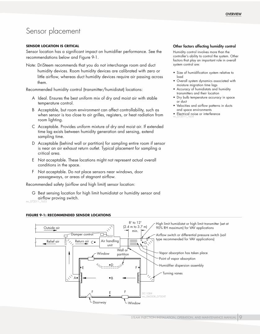
Other factors affecting humidity controlHumidity control involves more than the controller’s ability to control the system. Other factors that play an important role in overall system control are:
• Sizeofhumidificationsystemrelativetoload
• Overallsystemdynamicsassociatedwithmoisture migration time lags
• Accuracyofhumidistatsandhumiditytransmitters and their location
• Drybulbtemperatureaccuracyinspaceor duct
• Velocitiesandairflowpatternsinductsand space environments
• Electricalnoiseorinterferencemc_072011_1656
SENSOR LOCATION IS CRITICAL
Sensor location has a significant impact on humidifier performance. See the recommendations below and Figure 9-1.
Note: DriSteem recommends that you do not interchange room and duct humidity devices. Room humidity devices are calibrated with zero or little airflow, whereas duct humidity devices require air passing across them.
Recommended humidity control (transmitter/humidistat) locations:
A Ideal. Ensures the best uniform mix of dry and moist air with stable temperature control.
B Acceptable, but room environment can affect controllability, such as when sensor is too close to air grilles, registers, or heat radiation from room lighting.
C Acceptable. Provides uniform mixture of dry and moist air. If extended time lag exists between humidity generation and sensing, extend sampling time.
D Acceptable (behind wall or partition) for sampling entire room if sensor is near an air exhaust return outlet. Typical placement for sampling a critical area.
E Not acceptable. These locations might not represent actual overall conditions in the space.
F Not acceptable. Do not place sensors near windows, door passageways, or areas of stagnant airflow.
Recommended safety (airflow and high limit) sensor location:
G Best sensing location for high limit humidistat or humidity sensor and airflow proving switch.
mc_072011_1655
FIGURE 9-1: RECOMMENDED SENSOR LOCATIONS

10 STEAM INJECTION INSTALLATION, OPERATION, AND MAINTENANCE MANUAL
Pressurized steam piping guidelines
OVERVIEW
• SizepipinginaccordancewithASHRAErecommendations.
• Humidifier'ssteamsupplyshouldbetakenofftopofsteammain(notsideorbottom) to ensure the driest steam. Main should be dripped and trapped (in accordance with ASHRAE recommendations).
• Humidifiersteamtrap(s)mustdrainbygravitytoreturnmainhavinglittleor no back pressure. If condensate cannot drain by gravity, then it must be elevated to return main (see Figure 12-1 for instructions).
• Ifsteampressureislessthanorequalto15psi(103.4kPa),usefloatandthermostatic (F&T) traps for the humidifier.
If steam pressure is greater than 15 psi (103.4 kPa), use inverted bucket traps for the humidifier.
• Ifliftingcondensate,useaninvertedbuckettrapandcheckvalveregardlessof steam pressure. See Figure 12-1 for instructions.
• Condensatefromunavoidableheatlossinthedistributionsystemmustberemoved promptly to eliminate water hammer and degradation of steam quality and heat transfer capability. Install drip legs at all low points and natural drainage points in the system, such as at ends of mains; bottoms of risers; and ahead of pressure regulators, control valves, isolation valves, pipe bends, and expansion joints.
On straight, horizontal runs with no natural drainage points, space drip legs at the following intervals:
– Not exceeding 300' (91 m) when the pipe is pitched down in the direction of the steam flow
– At a maximum of 150' (46 m) when the pipe is pitched up, so that condensate flow is opposite of steam flow.
These distances apply to systems where valves are opened manually to remove air and excess condensate that forms during warm-up conditions. Reduce these distances by about half in systems that are warmed up automatically.
• Insulatepipingwelltoavoidunnecessaryheatloss.
• Pitchreturnlinesdownwardinthedirectionofthecondensateflowat1/2"per 10' (0.4%).
mc_051011_1544
11STEAM INJECTION INSTALLATION, OPERATION, AND MAINTENANCE MANUAL
DC-1200M
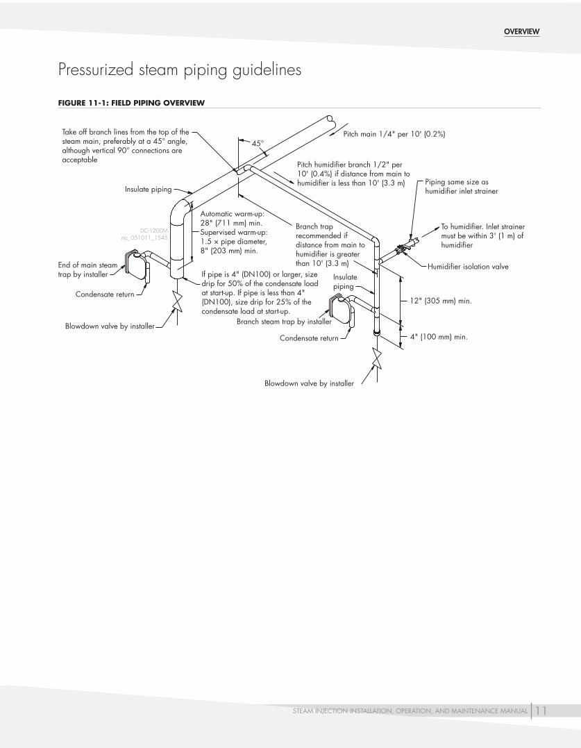
Condensate return
Piping same size as humidifier inlet strainer
Blowdown valve by installer
Humidifier isolation valve
12"(305mm)min.
4"(100mm)min.
Take off branch lines from the top of the steam main, preferably at a 45° angle, although vertical 90° connections are acceptable
Insulate piping
Blowdown valve by installer
End of main steam trap by installer
Automatic warm-up: 28"(711mm)min.Supervised warm-up:1.5 × pipe diameter, 8"(203mm)min.
Ifpipeis4"(DN100)orlarger,sizedrip for 50% of the condensate load atstart-up.Ifpipeislessthan4"(DN100), size drip for 25% of the condensate load at start-up.
Pitchhumidifierbranch1/2"per10' (0.4%) if distance from main to humidifier is less than 10' (3.3 m)
Condensate return
Branch trap recommended if distance from main to humidifier is greater than 10' (3.3 m)
Branch steam trap by installer
To humidifier. Inlet strainer must be within 3' (1 m) of humidifier
45°Pitchmain1/4"per10'(0.2%)
Insulatepiping
Pressurized steam piping guidelines
OVERVIEW
mc_051011_1545
FIGURE 11-1: FIELD PIPING OVERVIEW

12 STEAM INJECTION INSTALLATION, OPERATION, AND MAINTENANCE MANUAL
OVERVIEW
Inverted bucket steam trap
Check valve (swing type)
5' (1.5 m)maximum
Elevated condensate return main
1/2"pipethread(DN15)
Condensate return flow
Pitch1/2"per10'(0.4%)
DC-1064
In certain installations, it is not possible to drain the humidifier steam trap by gravity. The condensate must be lifted. Generally, lifting condensate is not recommended, but it can be done successfully by observing the following rules:
• Steam pressure. Theoretically, one pound (6.9 kPa) of steam pressure will lift condensate about 2' (0.6 m). But in practice, because of pipe friction, pressure drop through a steam trap, and back pressure in a return line, we recommendmaximumliftof6"perpound(0.2mper6.9kPa)ofsteampressureatthetrap.Forexample,asteam pressure of 5 psi (34.5 kPa) will provide a maximum lift of 2.5' (0.76 m). Lifting condensate more than 5' (1.5 m) should not be attempted.
• Steam trap. When lifting condensate, use an inverted bucket steam trap. Float and thermostatic (F&T) traps are more prone to water hammer damage with a flooded trap, which may occur when lifting condensate.
• Pipe size.Thesizeoftheverticalportionofthepipingshouldbe1/2"pipethread(DN15).
• Check valve (swing type). A low-pressure differential swing check valve should be installed adjacent to the trap. This will prevent backflow of condensate into the humidifier during periods of little or no steam pressure. Failure to do so could result in accumulated backflow discharging from the humidifier when steam pressure is resumed. Spring-type check valves are not recommended, as they can reduce pressure available for condensate lifts.
Condensate lifting recommendations:
1. Condensate can be lifted for all steam jacket piping.
2. Condensate could be lifted for connection to separator, but performance could vary based on variable pressure at the separator.
3. Condensate cannot be lifted for connection on headers for Multiple-tube humidifiers (including Maxi-bank option).
Pressurized steam piping guidelines
mc_051011_1530
FIGURE 12-1: ELEVATING CONDENSATE FROM A STEAM INJECTION HUMIDIFIER

13STEAM INJECTION INSTALLATION, OPERATION, AND MAINTENANCE MANUAL
OVERVIEW
DC-1488
Piping to be same size as valves
To Multiple-tube header inletUnion
From steam source
Separator
Piping to be same size as strainer
Piping to be same size as separator inlet
Union
Valve
Steam trap
12" (305 mm)
4"(100mm)
Steam trap
Piping to be same size as separator inlet
Separator
Isolation valve (by others)
Valve
To Multiple-tube header inlet
mc_042811_1450
Pressurized steam piping guidelines
Install strainer within 3' (1 m) of humidifier (see Note 2)
Notes:1. Dashed lines indicate provided by installer.2. Steam valve and strainer sizes are provided by DriCalc,
DriSteem's free sizing and selection software, available at www.dristeem.com.
FIGURE 13-1: MULTIPLE VALVE PLUMBING GUIDELINES
14 STEAM INJECTION INSTALLATION, OPERATION, AND MAINTENANCE MANUAL
OVERVIEW
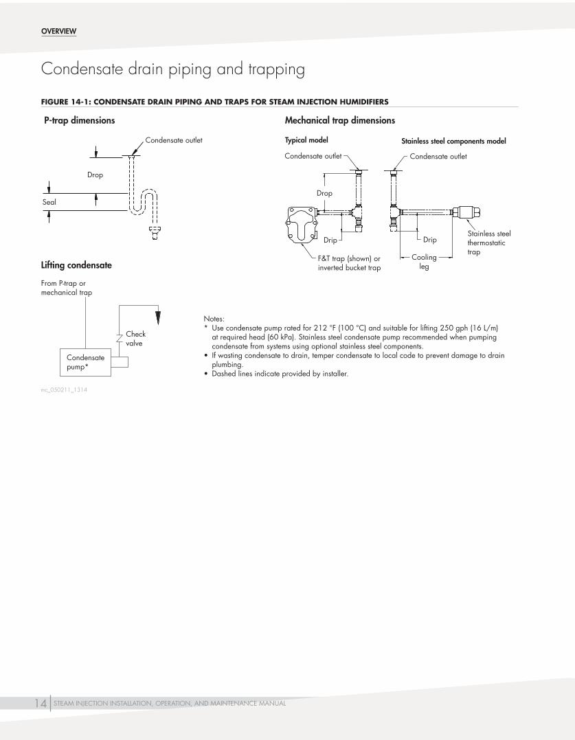
Condensate drain piping and trapping
P-trap dimensions
Condensate outlet
Drop
Seal
Lifting condensate
From P-trap or mechanical trap
Condensate pump*
Checkvalve
Notes:* Use condensate pump rated for 212 °F (100 °C) and suitable for lifting 250 gph (16 L/m)
at required head (60 kPa). Stainless steel condensate pump recommended when pumping condensate from systems using optional stainless steel components.
• Ifwastingcondensatetodrain,tempercondensatetolocalcodetopreventdamagetodrainplumbing.
• Dashedlinesindicateprovidedbyinstaller.
Mechanical trap dimensions
F&T trap (shown) or inverted bucket trap
Condensate outlet
Drop
Drip
Typical model
Condensate outlet
Drip
Coolingleg
Stainless steel thermostatic trap
Stainless steel components model
mc_050211_1314
FIGURE 14-1: CONDENSATE DRAIN PIPING AND TRAPS FOR STEAM INJECTION HUMIDIFIERS

15STEAM INJECTION INSTALLATION, OPERATION, AND MAINTENANCE MANUAL
OVERVIEW
Table 15-1:Condensate drain piping and traps for Steam Injection humidifiers
Single-tube, Mini-bank, and Multiple-tube humidifiers Area-type humidifier
Piping from separator*** Piping from steam jackets Piping from headerPiping from
separatorTypical model
Models with optional stainless steel components
Typical model
Models with optional stainless steel components
Typical model
Models with optional stainless steel components
P-trap water seal Do not use Do not use Do not use Do not use Do not use Do not use
Use with minimum:Drop:8" (203 mm)Seal:10" (254 mm)
F&T trap
Use if steam pressure is ≤15 psi
(103.4 kPa):Drop:12"(305mm) Drip:4"(102mm)
Do not use
Use only if not lifting condensate and steam pressure is
≤15 psi (103.4 kPa):Drop:12"(305mm) Drip:4"(102mm)
Do not use
Use with minimum:Drop:12" (305 mm)Drip:4"
(102 mm)
Do not use Do not use
Inverted bucket trap*
Use if steam pressure is
>15 psi (103.4 kPa):Drop:12"(305mm) Drip:4"(102mm)
Do not use
Use if lifting condensate or if steam pressure is
>15 psi (103.4 kPa):Drop:12"(305mm) Drip:4"(102mm)
Do not use Do not use Do not use Do not use
Stainless steel thermostatic trap
Do not use
Use with stainless steel
piping with minimum:
Drip:4"(102mm)Coolingleg:24"
(610 mm)
Do not use
Use with stainless steel piping with
minimum: Drip:4"(102mm) Coolingleg:24"
(610 mm)
Do not use
Use with stainless steel piping with
minimum: Drip:4"(102mm) Coolingleg:24"
(610 mm)
Do not use
Return condensate to boiler via nonpressurized return line?
Yes Yes Yes Yes Yes Yes No
Return condensate by condensate pump?
Yes Yes** Yes Yes** Yes Yes** Yes
Drain condensate to open drain?
Yes† Yes† Yes† Yes† Yes† Yes† Recommended†
Notes:* Trap may require priming after seasonal shutdown.** DriSteem recommends using a stainless steel condensate pump when pumping condensate from systems using optional stainless steel components.*** During consistent load, there may not be enough steam pressure in the separator to lift condensate from the separator using steam.† If wasting condensate to drain, temper condensate to local code to prevent damage to drain plumbing. mc_050211_1630
Condensate drain piping and trapping
16 STEAM INJECTION INSTALLATION, OPERATION, AND MAINTENANCE MANUAL
12"(305mm)min.
Pneumatic temperature switch
Steam trap
DC-1192
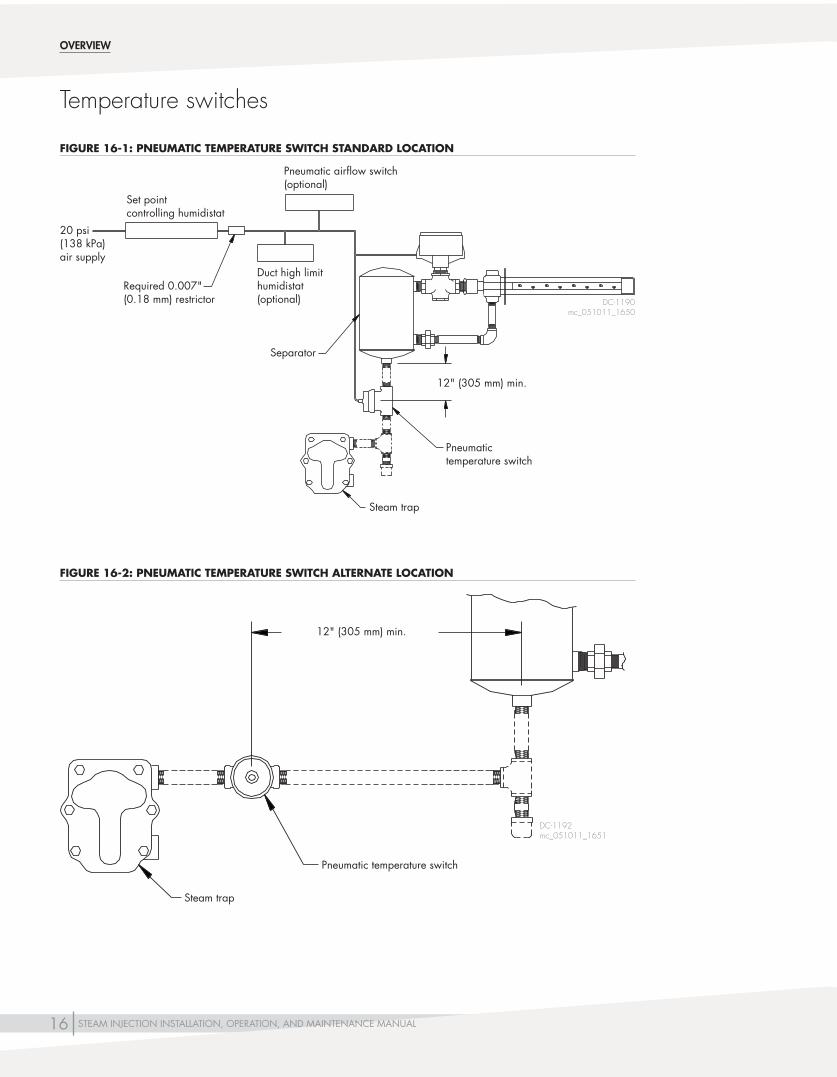
Temperature switches
OVERVIEW
Set point controlling humidistat
Required0.007"(0.18 mm) restrictor
Duct high limit humidistat(optional)
Pneumatic airflow switch(optional)
Separator
Steam trap
Pneumatic temperature switch
12"(305mm)min.
DC-1190mc_051011_1650
mc_051011_1651
FIGURE 16-1: PNEUMATIC TEMPERATURE SWITCH STANDARD LOCATION
FIGURE 16-2: PNEUMATIC TEMPERATURE SWITCH ALTERNATE LOCATION
20 psi (138 kPa) air supply

17STEAM INJECTION INSTALLATION, OPERATION, AND MAINTENANCE MANUAL
PNEUMATIC TEMPERATURE SWITCH NOTES:• DriSteem'spneumatictemperatureswitch,designedforusewitha
pneumatic control system, prevents condensate discharge from a steam injection humidifier during cold start or if the condensate return main becomes flooded. It accomplishes this by bleeding off the pneumatic signal from the controlling humidistat, preventing the pneumatic humidifier valve from opening until the steam trap has reached operating temperature.
• Thepneumatictemperatureswitchhasaself-containedairvalveoperatedby a thermal disc that is normally open, bleeding off control air pressure. When steam comes in contact with the thermal disc, the fluid inside the disc expands, causing the air valve to close, thus allowing the pneumatic control system air pressure to build up and to actuate the steam control valve.
• Installtheteecontainingthepneumatictemperatureswitchinthecondensate drainage pipe line between the separator and the inlet to the steam trap, as shown in the drawings on Pages 16 and 18.
mc_051011_1652
Temperature switches
OVERVIEW

18 STEAM INJECTION INSTALLATION, OPERATION, AND MAINTENANCE MANUAL
DC-1227
24 VACsecondary
Duct high limit humidistat (optional)
Airflow proving switch (optional)
Steam trap
Electric temperature switch
12"(305mm)min.
Normally closed electric modulating valve (120 VAC or 24 VAC)
Omit transformer when using 120 VAC coil
Class 2 transformer (by installer) used with 24 VAC coil
Electric modulating humidistat (optional) or control signal by others
120 VACprimary
Temperature switches
OVERVIEW
mc_051011_1653
FIGURE 18-1: ELECTRIC MODULATING TEMPERATURE SWITCH LOCATION

19STEAM INJECTION INSTALLATION, OPERATION, AND MAINTENANCE MANUAL
Temperature switches
OVERVIEW
Electric temperature switches:
• Theelectrictemperatureswitchpreventscondensatedischarge from a steam injection humidifier during a cold start or if the condensate return main becomes flooded. DriSteem's electric temperature switch is a temperature-actuated make-break switch designed for use with electric humidity control systems. The temperature at which it switches is adjustable and should be set at 210 °F (99 °C).
• Thisswitchpreventscondensatedischargefromasteam injection humidifier during a cold start or if the condensate return main becomes flooded.
• Installthesensingelementofthedeviceinthecondensatereturn piping on the inlet side of the steam trap (see drawings),includingateewitha½"pipethread(DN15)opening to receive the sensing element. When steam surrounds the sensing element, the switch will “make,” allowing the humidifier valve to open.
• Installallwiringaccordingtonationalandlocalelectricalcodes, and SIZE TRANSFORMER VA TO LOAD VA.
• Whenusingthetemperatureswitchwithanelectricmodulating valve, use the special wiring instructions furnished with the valve.
mc_051011_1654

20 STEAM INJECTION INSTALLATION, OPERATION, AND MAINTENANCE MANUAL
Configurations
Opposite connection
Elbow and union assembly
Union ring
OM-8
It may be necessary to change the steam discharge direction at the job site. To do so, follow these directions:1. Non-threaded union ring.
2. Remove elbow and nipple assembly from dispersion tube and reinstall on opposite connection.
3. Rotate dispersion tube 180° with respect to separator.
4. Reconnect union halves and tighten union ring.
5. Humidifier now will discharge to opposite side.
SINGLE-TUBE HUMIDIFIER
Drain
Steam inlet
Horizontal airflow
Drain
Steam inlet
Horizontal airflow
Drain
Steam inlet
Vertical airflowDrain
Steam inlet
Horizontal airflow
Steam inlet
Vertical airflow
Drain
Horizontal tube/horizontal airflowTypical configuration. Single-tube humidifiers are shipped this way unless ordered otherwise. See Page 24 for more information about this configuration. This is a right-hand configuration; to change to a left hand configuration, see Figure 20-1.
Vertical tube/horizontal airflowUse this configuration when there is no access to side of duct or when duct is tall and narrow, to improve steam absorption. See Page 27 for more information about this configuration.
Horizontal tube/vertical airflowUse this configuration in vertical airflow ducts. See Page 26 for more information about this configuration.
Horizontal separator/horizontal airflowUse this configuration when space is tight, such as when installing above ceilings. This application requires a separator designed for horizontal installation. See Page 25 for more information about this configuration.
Horizontal separator/vertical airflowUse this configuration in vertical airflow ducts and when space is tight, such as when installing above ceilings. This application requires a separator designed for horizontal installation.
OM-380, 381, 382, 383, 7652
FIGURE 20-2: CHANGING FROM RIGHT-HAND TO LEFT-HAND CONFIGURATION
FIGURE 20-1: SINGLE-TUBE HUMIDIFIER INSTALLATION CONFIGURATIONS
21STEAM INJECTION INSTALLATION, OPERATION, AND MAINTENANCE MANUAL
Assembly
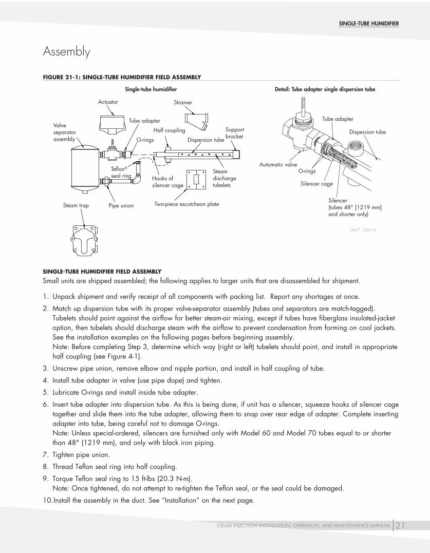
Detail: Tube adapter single dispersion tube
Dispersion tube
Silencer(tubes48"[1219mm]and shorter only)
Tube adapter
O-ringsAutomatic valve
Silencer cage
OM-7, OM-14
Hooks of silencer cage
Two-piece escutcheon plate
O-rings Dispersion tube
Valve separatorassembly
Tube adapter
Half coupling Support bracket
Teflon® seal ring
Pipe union
Actuator Strainer
Steam discharge tubelets
Steam trap
Single-tube humidifier
SINGLE-TUBE HUMIDIFIER FIELD ASSEMBLY
Small units are shipped assembled; the following applies to larger units that are disassembled for shipment.
1. Unpack shipment and verify receipt of all components with packing list. Report any shortages at once.
2. Match up dispersion tube with its proper valve-separator assembly (tubes and separators are match-tagged). Tubelets should point against the airflow for better steam-air mixing, except if tubes have fiberglass insulated-jacket option, then tubelets should discharge steam with the airflow to prevent condensation from forming on cool jackets. See the installation examples on the following pages before beginning assembly. Note: Before completing Step 3, determine which way (right or left) tubelets should point, and install in appropriate half coupling (see Figure 4-1).
3. Unscrew pipe union, remove elbow and nipple portion, and install in half coupling of tube.
4. Install tube adapter in valve (use pipe dope) and tighten.
5. Lubricate O-rings and install inside tube adapter.
6. Insert tube adapter into dispersion tube. As this is being done, if unit has a silencer, squeeze hooks of silencer cage together and slide them into the tube adapter, allowing them to snap over rear edge of adapter. Complete inserting adapter into tube, being careful not to damage O-rings. Note: Unless special-ordered, silencers are furnished only with Model 60 and Model 70 tubes equal to or shorter than48"(1219mm),andonlywithblackironpiping.
7. Tighten pipe union.
8. Thread Teflon seal ring into half coupling.
9. Torque Teflon seal ring to 15 ft-lbs (20.3 N-m). Note: Once tightened, do not attempt to re-tighten the Teflon seal, or the seal could be damaged.
10. Install the assembly in the duct. See “Installation” on the next page.
SINGLE-TUBE HUMIDIFIER
FIGURE 21-1: SINGLE-TUBE HUMIDIFIER FIELD ASSEMBLY

22 STEAM INJECTION INSTALLATION, OPERATION, AND MAINTENANCE MANUAL
Installation
1. Insert a support bolt in one of the support bracket’s three holes (upper, lower or end); cut holes in duct for inserting dispersion tube and support bolt.
2. Secure unit in duct with nut and support bolt. Mount two-piece escutcheon plate around tube and secure into duct with sheet metal screws. Where an airtight seal is required, use a suitable caulk around duct wall penetrations.
3. Install steam strainer and steam trap. Connect to steam and condensate return mains. See the drawings on the following pages and text below for detailed piping instructions.
4. Install control tubing (pneumatic) or wiring (electric) to valve actuator.
5. Install an airflow proving switch to prevent the valve from opening unless air is moving in duct. See “Humidifier placement” on Pages 6 – 8 for location recommendations.
6. Install a duct-mounted high-limit humidistat downstream from the humidifier. Set humidistat at 80-90% RH to prevent condensation forming in duct. Mount this humidistat far enough downstream to ensure that injected steam has been completely absorbed before the humidistat. See “Humidifier placement” on Pages 6 – 8 for location recommendations.
7. Install a temperature switch to prevent possible cold-start dripping when steam pressure to the humidifier is cycled. See “Temperature switches” on Pages 16 – 19 for more information.
8. Install the humidistat and/or sensors according to the recommendations on Page 9.
SINGLE-TUBE HUMIDIFIER
For more installation information•See“Humidifierplacement”onPages
6 – 8 for information about choosing an installation location.
•See“Sensorplacement”onPage9.•See“Pressurizedsteampipingguidelines”on
Pages 10 – 13.•See“Temperatureswitches”onPages
16 – 19.
WARNING
Excessive moisture hazardDriSteem strongly recommends installing a duct airflow proving switch and a duct high limit humidistat. These devices prevent a humidifier from making steam when there is low airflow in the duct or when the RH level in the duct is too high. Failure to install these devices can result in excessive moisture in the duct, which can cause bacteria and mold growth or dripping through the duct.
mc_060310_0725
WARNING
Improper mounting hazardMount humidifier per the instructions in this manual and to a structurally stable surface. Improper humidifier mounting can cause the humidifier to fall resulting in severe personal injury or death.
mc_060310_0725
23STEAM INJECTION INSTALLATION, OPERATION, AND MAINTENANCE MANUAL
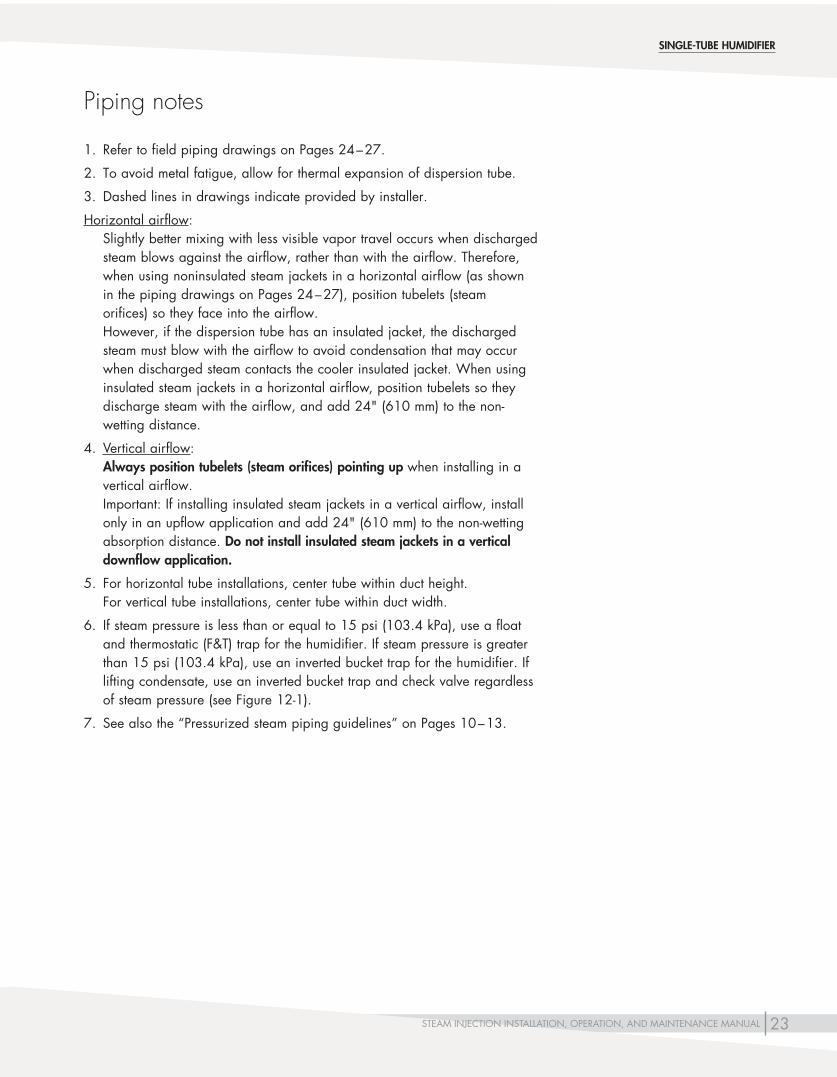
1. Refer to field piping drawings on Pages 24 – 27.
2. To avoid metal fatigue, allow for thermal expansion of dispersion tube.
3. Dashed lines in drawings indicate provided by installer.
Horizontal airflow: Slightly better mixing with less visible vapor travel occurs when discharged steam blows against the airflow, rather than with the airflow. Therefore, when using noninsulated steam jackets in a horizontal airflow (as shown in the piping drawings on Pages 24 – 27), position tubelets (steam orifices) so they face into the airflow. However, if the dispersion tube has an insulated jacket, the discharged steam must blow with the airflow to avoid condensation that may occur when discharged steam contacts the cooler insulated jacket. When using insulated steam jackets in a horizontal airflow, position tubelets so they dischargesteamwiththeairflow,andadd24"(610mm)tothenon-wetting distance.
4. Vertical airflow: Always position tubelets (steam orifices) pointing up when installing in a vertical airflow. Important: If installing insulated steam jackets in a vertical airflow, install onlyinanupflowapplicationandadd24"(610mm)tothenon-wettingabsorption distance. Do not install insulated steam jackets in a vertical downflow application .
5. For horizontal tube installations, center tube within duct height. For vertical tube installations, center tube within duct width.
6. If steam pressure is less than or equal to 15 psi (103.4 kPa), use a float and thermostatic (F&T) trap for the humidifier. If steam pressure is greater than 15 psi (103.4 kPa), use an inverted bucket trap for the humidifier. If lifting condensate, use an inverted bucket trap and check valve regardless of steam pressure (see Figure 12-1).
7. See also the “Pressurized steam piping guidelines” on Pages 10 – 13.
Piping notes
SINGLE-TUBE HUMIDIFIER

24 STEAM INJECTION INSTALLATION, OPERATION, AND MAINTENANCE MANUAL
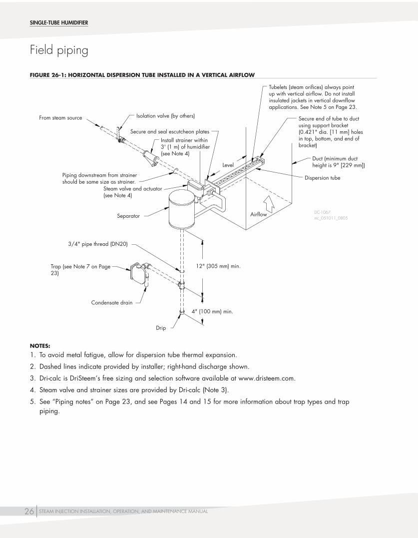
Field piping
SINGLE-TUBE HUMIDIFIER
DC-1065
From steam source
Install strainer within 3' (1 m) of humidifier (see Note 4)
Separator
Separator trap (see Note 5)
Condensate drain
12"(305mm)min.
Secure and seal escutcheon plates
Dispersion tube with noninsulated steam jacket (see Note 4 on Page 23)
LevelAirflow
Secure end of tube to duct using support bracket (0.42"[11mm]dia.holes in top, bottom, and end of bracket)
Steam valve and actuator (see Note 4)
Piping downstream from strainer should be the same size as strainer.
4"(100mm)min.
Drip
3/4"pipethread(DN20)
Minimum face height9"(229mm)
Isolation valve (by others)
NOTES:
1. To avoid metal fatigue, allow for dispersion tube thermal expansion.
2. 2. Dashed lines indicate provided by installer; right-hand discharge shown.
3. Dri-calc is DriSteem’s free sizing and selection software available at www.dristeem.com.
4. Steam valve and strainer sizes are provided by Dri-calc (Note 3).
5. See “Piping notes” on Page 23, and see Pages 14 and 15 for more information about trap types and trap piping.
mc_050511_1100
FIGURE 24-1: SINGLE-TUBE HUMIDIFIER WITH HORIZONTAL DISPERSION TUBE AND VERTICAL SEPARATOR INSTALLED IN A HORIZONTAL AIRFLOW

25STEAM INJECTION INSTALLATION, OPERATION, AND MAINTENANCE MANUAL
Field piping
From steam source
Separator
Trap (see Note 7 on Page 23)
Condensate drain
12"(305mm) min.
Secure and seal escutcheon plates
Dispersion tube with noninsulated steam jacket (see Note 4 on Page 23)
Level
Airflow
DC-1066
Piping downstream from strainer should be same size as strainer.
4"(100mm)min.
Drip
3/4"pipethread(DN20)
Duct
Minimumductwidth9"(229mm)
SINGLE-TUBE HUMIDIFIER
Secure end of tube to duct using supportbracket(0.42"[11mm]dia. holes in top, bottom, and end of bracket)
Isolation valve (by others)
Install strainer within 3' (1 m) of humidifier (see Note 4)
Steam valve and actuator (see Note 4)
NOTES:
1. To avoid metal fatigue, allow for dispersion tube thermal expansion.
2. Dashed lines indicate provided by installer; right-hand discharge shown.
3. Dri-calc is DriSteem’s free sizing and selection software available at www.dristeem.com.
4. Steam valve and strainer sizes are provided by Dri-calc (Note 3).
5. See “Piping notes” on Page 23, and see Pages 14 and 15 for more information about trap types and trap piping.
mc_050911_1600
FIGURE 25-1: SINGLE-TUBE HUMIDIFIER WITH HORIZONTAL DISPERSION TUBE AND HORIZONTAL SEPARATOR INSTALLED IN A HORIZONTAL AIRFLOW
26 STEAM INJECTION INSTALLATION, OPERATION, AND MAINTENANCE MANUAL
DC-1067
From steam source
Separator
Condensate drain
12"(305mm)min.
Secure and seal escutcheon plates
Dispersion tube
Secure end of tube to duct using support bracket (0.421"dia.[11mm]holesin top, bottom, and end of bracket)
Piping downstream from strainer should be same size as strainer.
4"(100mm)min.
Drip
3/4"pipethread(DN20)
Duct (minimum duct heightis9"[229mm])
Airflow
Level
Tubelets (steam orifices) always point up with vertical airflow. Do not install insulated jackets in vertical downflow applications. See Note 5 on Page 23.
SINGLE-TUBE HUMIDIFIER
Isolation valve (by others)
Steam valve and actuator (see Note 4)
Install strainer within 3' (1 m) of humidifier (see Note 4)
Trap (see Note 7 on Page 23)
NOTES:
1. To avoid metal fatigue, allow for dispersion tube thermal expansion.
2. Dashed lines indicate provided by installer; right-hand discharge shown.
3. Dri-calc is DriSteem’s free sizing and selection software available at www.dristeem.com.
4. Steam valve and strainer sizes are provided by Dri-calc (Note 3).
5. See “Piping notes” on Page 23, and see Pages 14 and 15 for more information about trap types and trap piping.
mc_051011_0805
Field piping
FIGURE 26-1: HORIZONTAL DISPERSION TUBE INSTALLED IN A VERTICAL AIRFLOW

27STEAM INJECTION INSTALLATION, OPERATION, AND MAINTENANCE MANUAL
From steam source
Separator
Condensate drain
12"(305mm)min.
Secure and seal escutcheon plates
Dispersion tube with noninsulated steam jacket (see Note 4 on Page 23)
Secure end of tube to duct using supportbracket(0.421"dia.[11mm]holes in both sides and end of bracket)
DC-1068
4"(100mm)min.
Drip
3/4"pipethread(DN20)
Duct (minimum duct width is 9"[229mm])
SINGLE-TUBE HUMIDIFIER
Install strainer within 3' (1 m) of humidifier (see Note 4)
Piping downstream from strainer should be same size as strainer.
Steam valve and actuator (see Note 4)
NOTES:
1. To avoid metal fatigue, allow for dispersion tube thermal expansion.
2. Dashed lines indicate provided by installer; right-hand discharge shown.
3. Dri-calc is DriSteem’s free sizing and selection software available at www.dristeem.com.
4. Steam valve and strainer sizes are provided by Dri-calc (Note 3).
5. See “Piping notes” on Page 23, and see Pages 14 and 15 for more information about trap types and trap piping.
Trap (see Note 7 on Page 23)
Airflow
Isolation valve (by others)
mc_051011_0830
Field piping
FIGURE 27-1: VERTICAL DISPERSION TUBE INSTALLED IN A HORIZONTAL AIRFLOW

28 STEAM INJECTION INSTALLATION, OPERATION, AND MAINTENANCE MANUAL
Field assembly
Note: For Maxi-bank option, follow the “Maxi-bank option field assembly and installation” instructions on Page 36.
1. Unpack shipment and verify receipt of all components with packing list. Report any shortages at once.
2. Plan the tube bank. You need to know the required spacing distance between tubes. See Table 29-1. Arrange tubes so steam will discharge against the airflow, unless tubes are insulated (optional), in which case they should blow with the air to prevent condensation on metal jacket covering insulation.
3. Assemble header based on spacings determined in Step 2 above. If header pipe size has not been specified, see Table 28-1. This table is based on a maximum steam velocity of 7,000 to 10,000 fpm (36 to 51 m/s), which will result in lower noise levels and produce uniform steam flow from all tubes. If noise level is not important or a uniform flow is not critical, a smaller header size may be used.
4. Install tube adapter fittings in header tees. (See Figure 28-1.) It usually works best to lay the header on the floor along with the tubes for Steps 5 – 7.
5. Install male pipe thread end of tube adapter into pipe fitting. Dope threads and tighten leak tight sealer.
6. O-rings are installed inside of tube adapter. NOTE: Use synthetic oil to lubricate O-rings before installing.
7. Insert tube adapter into dispersion tube. As this is being done, if unit has a silencer, squeeze hooks of silencer cage together and slide them into tube adapter, allowing them to snap over rear edge of adapter. Complete inserting adapter into tube, being careful not to damage O-rings. NOTE: Unless special-ordered, silencers are furnished only with Model 60 andModel70tubesequaltoorshorterthan48"(1219mm),andonlywith black iron piping.
8. Slide tube into adapter being careful not to damage O-rings.
9. Install tubes in adapter fittings, making sure tubelets are pointing in proper direction.
10. Cut to length, thread, and install steam jacket piping. NOTE: When the total tube length of dispersion tubes exceeds 45' (13.7 m), we recommend installing an additional steam inlet to the dispersion tubes and an additional steam jacket trap. One for each additional 45' of total tube length. Divide the tubes into equal groups. See Figures 32-1 and 35-1.
11. Make tube support strut using angle or channel iron, and bolt each tube end in place.
OM-15
Tube adapter
Dispersion tube
O-ringsHeader tee (by installer)
Use the tube adapter to connect a non-threaded tube to a threaded pipe fitting.
MULTIPLE-TUBE HUMIDIFIER
Table 28-1:Multiple-tube humidifier header sizes
Total capacity Header size
lbs/hr kg/h inches DN
up to 280 up to 127 1.5* 38*
up to 490 up to 222 2.0 50
491 to 980 223 to 444 3.0 80
981 to 1743 445 to 790 4.0 100
1744 to 2752 791 to 1248 5.0 125
2753 to 3989 1249 to 1809 6.0 150
* Non Maxi-bank only
mc_040710_1005
FIGURE 28-1: TUBE ADAPTER FOR MULTIPLE-TUBE HUMIDIFIERS

29STEAM INJECTION INSTALLATION, OPERATION, AND MAINTENANCE MANUAL
NOTE: For Maxi-bank option, follow the “Maxi-bank option field assembly and installation” instructions on Page 36.
1. Insert a support bolt in one of the three holes (upper, lower or end) of the support brackets; cut holes in duct for inserting dispersion tube and support bolt.
2. Secure unit in duct with nuts and support bolts. Mount two-piece escutcheon plate around each tube and secure into duct with sheet metal screws. Where an airtight seal is required, use a suitable caulk around duct wall penetrations.
3. Install steam strainer and steam trap. Connect to steam and condensate return mains. See the drawings on the following pages and text on the next for detailed piping instructions.
4. Install control tubing (pneumatic) or wiring (electric) to valve actuator.
5. Install an airflow proving switch to prevent the valve from opening unless air is moving in duct. See “Humidifier placement” on Pages 6 – 8 for location recommendations.
6. Install a duct-mounted high-limit humidistat downstream from the humidifier. Set humidistat at 80-90% RH to prevent condensation forming in duct. Mount this humidistat far enough downstream to ensure that injected steam has been completely absorbed before the humidistat. See “Humidifier placement” on Pages 6 – 8 for location recommendations.
7. Install a temperature switch to prevent possible cold-start dripping when steam pressure to the humidifier is cycled. See “Temperature switches” on Pages 16 – 19 for more information.
8. Install the humidistat and/or sensors according to the recommendations on Page 9.
Installation
MULTIPLE-TUBE HUMIDIFIER
Table 29-1:Multiple-tube humidifier minimum tube spacing
Tube model
Minimum tube spacing (X*) Multiple-tube humidifier
Minimum tube spacing (X*) Multiple-tube humidifier with op-
tional stainless steel piping
inches mm inches mm
60 6 152 9 229
70 9 229 9 229
80 9 229 12 305
* See Multiple-tube humidifier drawings on the following pages for center-to-center distance X.
mc_040710_1030
For more installation information•See“Humidifierplacement”onPages
6 – 8 for information about choosing an installation location.
•See“Sensorplacement”onPage9.•See“Pressurizedsteampipingguidelines”on
Pages 10 – 13.•See“Temperatureswitches”onPages
16 – 19.•SeetheMaxi-bankoptionbeginningonPage
36.
WARNING
Excessive moisture hazardDriSteem strongly recommends installing a duct airflow proving switch and a duct high limit humidistat. These devices prevent a humidifier from making steam when there is low airflow in the duct or when the RH level in the duct is too high. Failure to install these devices can result in excessive moisture in the duct, which can cause bacteria and mold growth or dripping through the duct. mc_060310_0725
WARNING
Improper mounting hazardMount humidifier per the instructions in this manual and to a structurally stable surface. Improper humidifier mounting can cause the humidifier to fall resulting in severe personal injury or death.
mc_060310_0725

30 STEAM INJECTION INSTALLATION, OPERATION, AND MAINTENANCE MANUAL
NOTE: For Maxi-bank option, see the “Maxi-bank option piping notes” on Page 36.
1. Refer to piping drawings on Pages 31 through 35.
2. See also the “Pressurized steam piping guidelines” on Pages 10 through 13.
3. Slightly better mixing with less visible vapor travel occurs when discharged steam blows against the airflow, rather than with the airflow. Therefore, when using noninsulated steam jackets in a horizontal airflow (as shown in the drawings), position dispersion tubelets (steam orifices) so that they face into the airflow. If the dispersion tube has an insulated jacket, the discharged steam must blow with the airflow to avoid condensation that may occur when discharged steam contacts the cooler insulated jacket. Therefore, when using insulated steam jackets in a horizontal airflow, position dispersion tubelets so that they discharge steam with theairflow,andalsoadd24"(610mm)tothenon-wettingabsorptiondistance.
4. Jacket piping size:• 1/2"pipethread(DN15)forModel60tubes
• 3/4"pipethread(DN20)forModel70tubes
• 1½"pipethread(DN40)forModel80tubes
5. To ensure uniform output from each tube, connect steam supply as close to the middle of the header as possible, but not in direct alignment with a dispersion tube.
6. See header sizing in Table 28-1.
7. After the unit is installed, secure steam jacket piping to the tube header.
8. If steam pressure is less than or equal to 15 psi (103.4 kPa), use float and thermostatic (F&T) traps for the humidifier. If steam pressure is greater than 15 psi (103.4 kPa), use inverted bucket traps for the humidifier. If lifting condensate, use an inverted bucket trap and check valve regardless of steam pressure (Figure 12-1).
9. Due to the pressure drop across the valve, the steam pressure at the header trap is minimal; therefore, you cannot lift condensate or return condensate to a pressurized return by steam pressure from this trap. However, with condensate free steam, no trap is required if load is less than 500 pph, and between 500 and 1000 pph a trap is optional. Above 1000 pph, a trap is recommended.
10. X = distance between tubes, center to center Y=clearanceattopandbottom=atleast1/2ofXor4½"(114mm),whichever is greater, but not greater than X See the minimum tube spacing in Table 29-1.
11. When installing in a vertical airflow: Always point tubelets (steam orifices) up when installing in a vertical airflow.
I m p o r t a n t : If installing insulated steam jackets in a vertical airflow, install only in an upflow application and add 24" (610 mm) to the non-wetting absorption distance. Do not install insulated steam jackets in a vertical downflow application .
Piping notes
MULTIPLE-TUBE HUMIDIFIER
For total dispersion tube lengths of more than 45’ (13.7 m), see Step 10 note on Page 28.

31STEAM INJECTION INSTALLATION, OPERATION, AND MAINTENANCE MANUAL
From steam source
Header trap by installer (See Note 9 on Page 30)
Same size as separator inlet
See header sizes in Table 28-1
Separator
Separator trap (see Note 8 on Page 30)
3/4"pipethread(DN20)
Secure and seal escutcheon plates
See Note 7 on Page 30
Dispersion tubes (see Note 3 on Page 30)
Escutcheon plate
Level
Steam jacket piping (see Note 4 on Page 30)
Header (see Table 28-1)
x
x
x
x
DC-1070
Dispersion tube header (insulated)
Secure end of tube to duct using supportbracket(0.421"dia.[11mm]holesintop,bottom,and end of bracket)
Tube adapter
12"(305mm)min.
4"(100mm)min.
12"(305mm)min.
4"(100mm)min.
Field piping
MULTIPLE-TUBE HUMIDIFIER
y=4½"(114mm)min.Center assembly in duct. See Note 10 on Page 30.
y (see y note above)
x (See Table 29-1 for minimum tube spacing)
mc_040611_1225
Steam jacket trap (see Note 8 on Page 30)
Isolation valve (by others)
Notes:
1. To avoid metal fatigue, allow for thermal expansion of dispersion tubes.
2. Dashed lines indicate provided by installer (see Maxi-bank option beginning on Page 36). Right-hand discharge shown.
3. Dri-calc is DriSteem’s free sizing and selection software available at www.dristeem.com.
4. Steam valve and strainer sizes are provided by Dri-calc (Note 3).
Install strainer within 3' (1 m) of humidifier (see Note 4)
Steam valve and actuator (see Note 4)
FIGURE 31-1: MULTIPLE-TUBE HUMIDIFIER, TOTAL TUBE LENGTH LESS THAN OR EQUAL TO 45' (13.7 M)
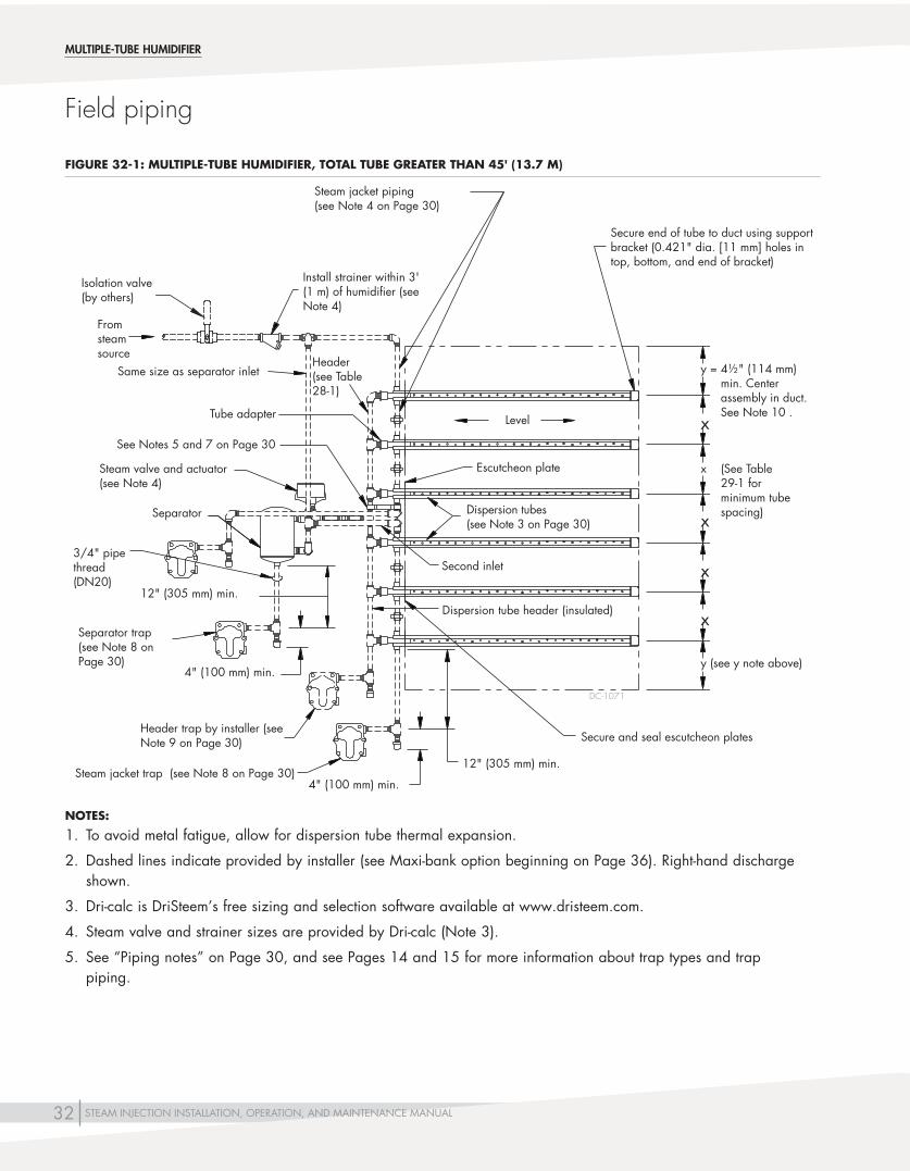
32 STEAM INJECTION INSTALLATION, OPERATION, AND MAINTENANCE MANUAL
Fromsteamsource
Header trap by installer (see Note 9 on Page 30)
Same size as separator inlet
See Notes 5 and 7 on Page 30
Separator
Separator trap (see Note 8 on Page 30)
3/4"pipethread(DN20)
Secure and seal escutcheon plates
Second inlet
Dispersion tubes (see Note 3 on Page 30)
Escutcheon plate
Level
Steam jacket piping (see Note 4 on Page 30)
Header (see Table 28-1)
x
x
x
x
DC-1071
Dispersion tube header (insulated)
Secure end of tube to duct using support bracket(0.421"dia.[11mm]holesintop, bottom, and end of bracket)
Tube adapter
12"(305mm)min.
4"(100mm)min.
4"(100mm)min.
12"(305mm)min.
Field piping
MULTIPLE-TUBE HUMIDIFIER
Install strainer within 3' (1 m) of humidifier (see Note 4)
y=4½"(114mm)min. Center assembly in duct. See Note 10 .
y (see y note above)
x (See Table 29-1 for minimum tube spacing)
NOTES:
1. To avoid metal fatigue, allow for dispersion tube thermal expansion.
2. Dashed lines indicate provided by installer (see Maxi-bank option beginning on Page 36). Right-hand discharge shown.
3. Dri-calc is DriSteem’s free sizing and selection software available at www.dristeem.com.
4. Steam valve and strainer sizes are provided by Dri-calc (Note 3).
5. See “Piping notes” on Page 30, and see Pages 14 and 15 for more information about trap types and trap piping.
Isolation valve (by others)
Steam valve and actuator (see Note 4)
Steam jacket trap (see Note 8 on Page 30)
FIGURE 32-1: MULTIPLE-TUBE HUMIDIFIER, TOTAL TUBE GREATER THAN 45' (13.7 M)

33STEAM INJECTION INSTALLATION, OPERATION, AND MAINTENANCE MANUAL
y
y x
See Table 29-1 for minimum tube spacing (x). See Note 10 on Page 30.
Level
Airflow (see Note 11 on Page 30)
Secure end of tube to duct using supportbracket(0.421"dia.[11mm]holesinsidesandend)
Dispersion tube (see Note 11 on Page 30)
See Note 7 on Page 30
See Note 2 on Page 30
See Note 9 on Page 30
Pitchheader1/8"/ft(1%)towardheader trap drain
Condensate return
Trap
Separator
Same size as separator inlet
From steam source
See Note 4 on Page 30
Secure and seal escutcheon plates
Duct
x
x
DC-1074
Field piping
MULTIPLE-TUBE HUMIDIFIER
Install strainer within 3' (1 m) of humidifier (see Note 4)
Notes:
1. To avoid metal fatigue, allow for dispersion tube thermal expansion.
2. Dashed lines indicate provided by installer (see Maxi-bank option beginning on Page 36). Right-hand discharge shown.
3. Dri-calc is DriSteem’s free sizing and selection software available at www.dristeem.com.
4. Steam valve and strainer sizes are provided by Dri-calc (Note 3).
5. See “Piping notes” on Page 30, and see Pages 14 and 15 for more information about trap types and trap piping.
Isolation valve (by others)
Steam valve and actuator (see Note 4)
y=4½"(114mm)min.Center assembly in duct. See Note 10 on Page 30.
mc_051011_0902
FIGURE 33-1: MULTIPLE-TUBE HUMIDIFIER INSTALLED IN A VERTICAL AIRFLOW

34 STEAM INJECTION INSTALLATION, OPERATION, AND MAINTENANCE MANUAL
From steam source
Header trap by installer (see Note 9 on Page 30)
Same size as separator inlet
See Note 5 on Page 30
Separator
3/4"pipethread(DN20)
Dispersion tubes (see Note 3 on Page 30)
Level
x
x
x
DC-1204
Tube adapter
12” (305 mm) min.
4"(100mm)min.
4"(100mm)min.
12"(305mm)min.
Field piping
MULTIPLE-TUBE HUMIDIFIER
Isolation valve (by others)
See Note 7 on Page 30
Separator trap (see Note 8 on Page 30)
Install strainer within 3' (1 m) of humidifier (see Note 4)
y=4½"(114mm)min. Center assembly in duct. See Note 10 on Page 30.
y (see y note above)
x (See Table 29-1 for minimum tube spacing)
Secure end of tube to AHU using supportbracket(0.421”dia.[11mm]holesintop,bottom,andendof bracket)
NOTES:
1. To avoid metal fatigue, allow for thermal expansion of dispersion tubes.
2. Dashed lines indicate provided by installer (see Maxi-bank option beginning on Page 36). Right-hand discharge shown.
3. Dri-calc is DriSteem’s free sizing and selection software available at www.dristeem.com.
4. Steam valve and strainer sizes are provided by Dri-calc (Note 3).
5. See Pages 14 and 15 for more information about trap types and piping.
Steam jacket trap (see Note 8 on Page 30)
Steam jacket piping (see Note 4 on Page 30)
Steam valve and actuator (see Note 4)
mc_050511_1455
xDispersion tube header (insulated) (see Table 28-1)
FIGURE 34-1: MULTIPLE-TUBE HUMIDIFIER WITH TOTAL TUBE LENGTH LESS THAN OR EQUAL TO 45' (13.7 M) IN A AHU

35STEAM INJECTION INSTALLATION, OPERATION, AND MAINTENANCE MANUAL
Field piping
MULTIPLE-TUBE HUMIDIFIER
From steam source
Same size as separator inlet
See Note 7 on Page 30
Separator
Separator trap (see Note 8 on Page 30)
3/4”pipe thread (DN20)
Second inlet
Level
x
x
x
DC-1205
Dispersion tube header (insulated) (see Table 28-1)
Tube adaptor
12"(305mm)min.4"(102mm)min.
Steam jacket trap (see Note 8 on Page 30)
12"(305mm)min.
4"(102mm)min.
Header trap (see Note 9 on Page 30)
Securebrackettoductusing0.375" (9.5 mm) dia. holes in end of bracket
y (see y note above)
x (See Table 29-1 for minimum tube spacing)
Isolation valve (by others)
Dispersion tubes (see Note 3 on Page 30)
mc_040711_1705
NOTES:
1. To avoid metal fatigue, allow for thermal expansion of dispersion tubes.
2. Dashed lines indicate provided by installer (see Maxi-bank option beginning on Page 36). Right-hand discharge shown.
3. Dri-calc is DriSteem’s free sizing and selection software available at www.dristeem.com.
4. Steam valve and strainer sizes are provided by Dri-calc (Note 3).
5. See Pages 14 and 15 for more information about trap types and piping.
Install strainer within 3' (1 m) of humidifier (see Note 4)
Steam valve and actuator (see Note 4)
y=4½"(114mm)min. Center assembly in duct. See Note 10 on Page 30.
x
Steam jacket trap (see Note 8 on Page 30)
Steam jacket piping (see Note 4 on Page 30)
4"(102mm)min.
FIGURE 35-1: MULTIPLE-TUBE HUMIDIFIER WITH TOTAL TUBE LENGTH GREATER THAN 45' (13.7 M) IN A AHU

36 STEAM INJECTION INSTALLATION, OPERATION, AND MAINTENANCE MANUAL
Maxi-bank option field assembly and installation
The Maxi-bank humidifier’s header piping and steam-jacket piping are provided by DriSteem. The Maxi-bank is factory assembled and shipped intact, except for larger units that are broken down for shipment. If the unit you are installing is already assembled, skip installation steps that do not apply.
1. Unpack shipment and verify receipt of all Maxi-bank components with packing list. Report any shortages at once.
2. To simplify installation, we recommend that dispersion tubes be attached to the Maxi-bank header before dispersion tubes and header are installed in a duct or air handler.
3. Follow the pre-tagged component lettering and match up dispersion tubes (or tube sections) to their proper location on the Maxi-bank header.
4. Install each dispersion tube into its appropriate tube adapter on the header, being sure to lubricate O-rings in the tube adapters.
5. Proceed with the additional tubes. Bring the jacketed union halves together and secure unions by hand. NOTE: When the total tube length of dispersion tubes exceeds 45' (13.7 m), we recommend installing an additional steam inlet to the dispersion tubes and an additional steam jacket trap. One for each additional 45' of total tube length. Divide the tubes into equal groups. See Figures 41-1 and 43-1.
6. When all the dispersion tubes are assembled, place the tube assembly into the duct or air handler, securing the assembly and tube ends to the duct or a fabricated structure. Install tubes level.
7. Position and secure header, then tighten interconnecting tube jacket unions. When installing into a duct, use the two-piece escutcheon plates around each tube and secure to duct with sheet metal screws. In duct applications where air tightness is required, seal around tube and bolts with suitable caulk.
MAXI-BANK HUMIDIFIER
For more installation information•See“Humidifierplacement”onPages
6 – 8 for information about choosing an installation location.
•See“Sensorplacement”onPage9.•See“Pressurizedsteampipingguidelines”on
Pages 10 – 13.•See“Temperatureswitches”onPages
16 – 19.
WARNING
Excessive moisture hazardDriSteem strongly recommends installing a duct airflow proving switch and a duct high limit humidistat. These devices prevent a humidifier from making steam when there is low airflow in the duct or when the RH level in the duct is too high. Failure to install these devices can result in excessive moisture in the duct, which can cause bacteria and mold growth or dripping through the duct.
mc_060310_0725
WARNING
Improper mounting hazardMount humidifier per the instructions in this manual and to a structurally stable surface. Improper humidifier mounting can cause the humidifier to fall resulting in severe personal injury or death.
mc_060310_0725

37STEAM INJECTION INSTALLATION, OPERATION, AND MAINTENANCE MANUAL
8. Locate and install separator/valve assembly to Maxi-bank mating union on header and tighten union.
9. Install strainer and necessary steam traps. Connect assembly to steam and condensate mains.
10. Install control tubing (pneumatic) or wiring (electric) to valve actuator.
11. Install an airflow proving switch to prevent the valve from opening unless air is moving in duct. See “Humidifier placement” on Pages 6 – 8 for location recommendations.
12. Install a duct-mounted high-limit humidistat downstream from the humidifier. Set humidistat at 80-90% RH to prevent condensation forming in the duct. Mount this humidistat far enough downstream to ensure that injected steam has been completely absorbed before the humidistat. See “Humidifier placement” on Pages 6 – 8 for location recommendations.
13. Install a temperature switch to prevent possible cold-start dripping when steam pressure to the humidifier is cycled. See “Temperature switches” on Pages 16 – 19 for more information.
14. Install the humidistat and/or sensors according to the recommendations on Page 9.
15. Pressure test system, and secure fittings as necessary.
Maxi-bank option field assembly and installation
MAXI-BANK HUMIDIFIER
38 STEAM INJECTION INSTALLATION, OPERATION, AND MAINTENANCE MANUAL
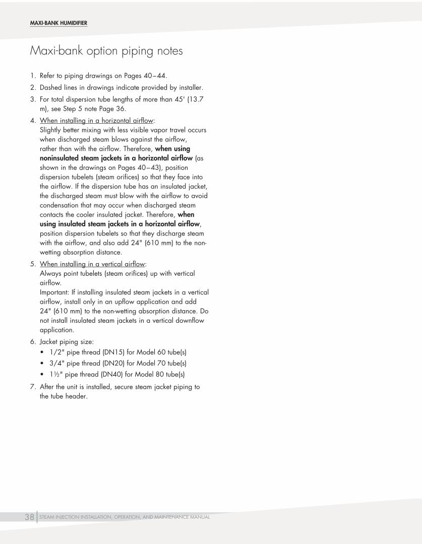
Maxi-bank option piping notes
MAXI-BANK HUMIDIFIER
1. Refer to piping drawings on Pages 40 – 44.
2. Dashed lines in drawings indicate provided by installer.
3. For total dispersion tube lengths of more than 45' (13.7 m), see Step 5 note Page 36.
4. When installing in a horizontal airflow: Slightly better mixing with less visible vapor travel occurs when discharged steam blows against the airflow, rather than with the airflow. Therefore, when using noninsulated steam jackets in a horizontal airflow (as shown in the drawings on Pages 40 – 43), position dispersion tubelets (steam orifices) so that they face into the airflow. If the dispersion tube has an insulated jacket, the discharged steam must blow with the airflow to avoid condensation that may occur when discharged steam contacts the cooler insulated jacket. Therefore, when using insulated steam jackets in a horizontal airflow, position dispersion tubelets so that they discharge steam withtheairflow,andalsoadd24"(610mm)tothenon-wetting absorption distance.
5. When installing in a vertical airflow: Always point tubelets (steam orifices) up with vertical airflow. Important: If installing insulated steam jackets in a vertical airflow, install only in an upflow application and add 24"(610mm)tothenon-wettingabsorptiondistance.Donot install insulated steam jackets in a vertical downflow application.
6. Jacket piping size:• 1/2"pipethread(DN15)forModel60tube(s)
• 3/4"pipethread(DN20)forModel70tube(s)
• 1½"pipethread(DN40)forModel80tube(s)
7. After the unit is installed, secure steam jacket piping to the tube header.

39STEAM INJECTION INSTALLATION, OPERATION, AND MAINTENANCE MANUAL
Maxi-bank option piping notes
MAXI-BANK HUMIDIFIER
8. If steam pressure is less than or equal to 15 psi (103.4 kPa), use float and thermostatic (F&T) traps for the humidifier. If steam pressure is greater than 15 psi (103.4 kPa), use inverted bucket traps for the humidifier. If lifting condensate, use an inverted bucket trap and check valve regardless of steam pressure (see Figure 12-1).
9. The header trap is required to collect condensate from the header assembly. Due to the pressure drop across the valve, the steam pressure at the header trap is minimal; therefore, you cannot lift condensate by steam pressure, or return condensate to a pressurized return, from this trap. On small headers(2"orlessindiameter),thistrapmaybeomitted.
10. X = distance between tubes, center to center Y=clearanceattopandbottom=atleast½Xor4½"(114.3 mm), whichever is greater, but not greater than X See the “Minimum tube spacing distance” table on Page 38.
11. See “Pressurized steam piping guidelines” on Pages 10 – 13.
12. Drawings represent right-hand discharge.
13. See Table 28-1 for header sizing.

40 STEAM INJECTION INSTALLATION, OPERATION, AND MAINTENANCE MANUAL
Mounting bracket
See Table 28-1
Secure and seal escutcheon plates
See Note 7 on Page 38
Escutcheon plate
Level
Steam jacket piping (See Note 6 on Page 38)
x
x
x
x
DC-1072
Secure end of tube to duct using supportbracket(0.421"dia.[11mm]holesintop,bottom,andendofbracket)
12"(305mm)min.
4"(100mm)min.
Dispersion tubes (see Note 4 on Page 38)
Maxi-bank option field piping
MAXI-BANK HUMIDIFIER
NOTES:
1. To avoid metal fatigue, allow for dispersion tube thermal expansion.
2. Dashed lines indicate provided by installer; right-hand discharge shown.
3. Dri-calc is DriSteem’s free sizing and selection software available at www.dristeem.com.
4. Steam valve and strainer sizes are provided by Dri-calc (Note 3).
5. See “Maxi-bank option piping notes” on Pages 38 and 39, and see Pages 14 and 15 for more information about trap types and trap piping.
Same size as separator inlet
From steam source
Factory-supplied header and interconnecting piping
Steam valve and actuator (see Note 4)
Separator
3/4"pipethread(DN20)
12"(305mm)min.
Trap (See Note 8 on Page 39)
4"(100mm)min.
Header trap by installer (see Note 9 on Page 39)
y (see y note above)
x (See Table 29-1 for minimum tube spacing)
y=4½"(114mm)min. Center assembly in duct. See Note 10 on Page 39.
Install strainer within 3' (1 m) of humidifier (see Note 4)
Isolation valve (by others)
Steam jacket trap (see Note 8 on Page 39)
mc_040611_1550
FIGURE 40-1: MAXI-BANK OPTION, TOTAL TUBE LENGTH LESS THAN OR EQUAL TO 45' (13.7 M)

41STEAM INJECTION INSTALLATION, OPERATION, AND MAINTENANCE MANUAL
From steam source
Header trap by installer (see Note 9 on Page 39)
Same size as separator inlet
See Table 28-1
Separator
Trap (See Note 8 on Page 39)
3/4"pipethread (DN20)
Secure and seal escutcheon plates
Second inlet
Dispersion tubes (see Note 4 on Page 38)
Escutcheon plate
Level
Steam jacket piping (See Note 6 on Page 38)
Factory-supplied header and interconnecting piping
x
x
x
x
DC-1073
Secure end of tube to duct using supportbracket(0.421"dia.[11mm]holesintop,bottom,andend of bracket)
See Note 7 on Page 38
12"(305mm)min.
4"(100mm)min.
4"(100mm)min.
12"(305mm)min.
Mounting bracket
Maxi-bank option field piping
MAXI-BANK HUMIDIFIER
Install strainer within 3' (1 m) of humidifier (see Note 4)
NOTES:
1. To avoid metal fatigue, allow for dispersion tube thermal expansion.
2. Dashed lines indicate provided by installer; right-hand discharge shown.
3. Dri-calc is DriSteem’s free sizing and selection software available at www.dristeem.com.
4. Steam valve and strainer sizes are provided by Dri-calc (Note 3).
5. See “Maxi-bank option piping notes” on Pages 38 and 39, and see Pages 14 and 15 for more information about trap types and trap piping.
Isolation valve (by others)
y (see y note above)
x (See Table 29-1 for minimum tube spacing)
y=4½"(114mm)min. Center assembly in duct. See Note 10 on Page 39.
Steam valve and actuator (see Note 4)
Steam jacket trap (see Note 8 on Page 39)
mc_051011_1018
FIGURE 41-1: MAXI-BANK OPTION, TOTAL TUBE LENGTH GREATER THAN 45' (13.7 M)

42 STEAM INJECTION INSTALLATION, OPERATION, AND MAINTENANCE MANUAL
Mounting bracket
Level
DC-1207
Secure end of tube to AHU using supportbracket(0.421"dia.[11mm]holesintop,bottom,andend of bracket)
12"(305mm)min.4"(100mm)min.
4"(100mm)min.
Maxi-bank option field piping
MAXI-BANK HUMIDIFIER
See Table 28-1
See Note 7 on Page 38
Steam jacket piping (See Note 6 on Page 38)
x
x
x
x
Dispersion tubes (see Note 4 on Page 38)
NOTES:
1. To avoid metal fatigue, allow for dispersion tube thermal expansion.
2. Dashed lines indicate provided by installer; right-hand discharge shown.
3. Dri-calc is DriSteem’s free sizing and selection software available at www.dristeem.com.
4. Steam valve and strainer sizes are provided by Dri-calc (Note 3).
5. See “Maxi-bank option piping notes” on Pages 38 and 39, and see Pages 14 and 15 for more information about trap types and trap piping.
Same size as separator inlet
From steam source
Factory-supplied header and interconnecting piping
Steam valve and actuator (see Note 4)
Separator
3/4"pipethread(DN20)
12"(305mm)min.
Header trap by installer (see Note 9 on Page 39)
y (see y note above)
x (See Table 29-1 for minimum tube spacing)
y=4½"(114mm)min. Center assembly in duct. See Note 10 on Page 39.
Install strainer within 3' (1 m) of humidifier (see Note 4)
Isolation valve (by others)
mc_050511_1456
Steam jacket trap (see Note 8 on Page 39)
Separator trap (See Note 8 on Page 39)
FIGURE 42-1: MAXI-BANK OPTION, TOTAL TUBE LENGTH LESS THAN OR EQUAL TO 45' (13.7 M) IN AN AHU

43STEAM INJECTION INSTALLATION, OPERATION, AND MAINTENANCE MANUAL
Second inlet
Level
DC-1208
Secure end of tube to AHU using supportbracket(0.421"dia.[11mm]holesintop,bottom,and end of bracket)
12"(305mm)min.
Mounting bracket
Maxi-bank option field piping
MAXI-BANK HUMIDIFIER
From steam source
Header trap by installer (see Note 9 on Page 39)
Same size as separator inlet
See Table 28-1
Separator
Separator trap (See Note 8 on Page 39)
3/4"pipethread (DN20)
Dispersion tubes (see Note 4 on Page 38)
Steam jacket piping (See Note 6 on Page 38)
Factory-supplied header and interconnecting piping
x
x
x
x
See Note 7 on Page 38
4"(100mm)min.
4"(100mm)min.
12"(305mm)min.
Install strainer within 3' (1 m) of humidifier (see Note 4)
NOTES:
1. To avoid metal fatigue, allow for dispersion tube thermal expansion.
2. Dashed lines indicate provided by installer; right-hand discharge shown.
3. Dri-calc is DriSteem’s free sizing and selection software available at www.dristeem.com.
4. Steam valve and strainer sizes are provided by Dri-calc (Note 3).
5. See “Maxi-bank option piping notes” on Pages 38 and 39, and see Pages 14 and 15 for more information about trap types and trap piping.
Isolation valve (by others)
y (see y note above)
x (See Table 29-1 for minimum tube spacing)
y=4½"(114mm)min. Center assembly in duct. See Note 10 on Page 39.
Steam valve and actuator (see Note 4)
mc_050511_1457Steam jacket trap (see Note 8 on Page 39)
FIGURE 43-1: MAXI-BANK OPTION, TOTAL TUBE LENGTH GREATER THAN 45' (13.7 M) IN AN AHU

44 STEAM INJECTION INSTALLATION, OPERATION, AND MAINTENANCE MANUAL
Valve
Pipe size same as inlet to separator
Separator
Trap (see Note 8 on Page 39)
See Note 2 on Page 38
Secure and seal escutcheon plates
Airflow (see Note 5 on Page 38)
Dispersion tube (see Note 5 on Page 38)
Pitch supply header 1/8"/ft(1%)towarddrain
Level
Header trap(see Note 9 on Page 39)
See Note 2 on Page 38
DC-1075
Secureendoftubetoductusingsupportbracket(0.421"dia.[11mm]holesinbothsidesandendofbracket)
x
x
x
x
x
y
See Note 7 on Page 38
From steam source
Maxi-bank option field piping
mc_040711_1805
MAXI-BANK HUMIDIFIER
Install strainer within 3' (1 m) of humidifier (see Note 4)
NOTES:
1. To avoid metal fatigue, allow for dispersion tube thermal expansion.
2. Dashed lines indicate provided by installer; right-hand discharge shown.
3. Dri-calc is DriSteem’s free sizing and selection software available at www.dristeem.com.
4. Steam valve and strainer sizes are provided by Dri-calc (Note 3).
5. See “Maxi-bank option piping notes” on Pages 38 and 39, and see Pages 14 and 15 for more information about trap types and trap piping.
See Table 29-1 for minimum tube spacing (x). See Note 10 on Page 39.
y=4½"(114mm)min.Center assembly in duct. See Note 10 on Page 39.
Isolation valve (by others)
y
FIGURE 44-1: MAXI-BANK OPTION INSTALLED IN A DUCT VERTICAL AIRFLOW

45STEAM INJECTION INSTALLATION, OPERATION, AND MAINTENANCE MANUAL
The Mini-bank humidifier is a pre-engineered and pre-assembled header/tube assembly with tubes that are always 3"(76.2mm)oncenter.Thenumberoftubesdependsuponthe duct height. For best mixing, the tubes should span at least 90% (preferably 100%) of the duct width.
1. Unpack shipment and verify receipt of all components with packing list. Two F&T traps and one wye strainer are shipped loose for field installation. Report any shortages at once.
2. The Mini-bank can be configured to discharge steam against or with the airflow: Position the tube bank assembly at the desired orientation, slide the tube bank through the opening in the duct wall, join the tube bank assembly to the separator/valve assembly, and tighten the union.
3. Slightly better mixing with less “fog travel” results when the steam blows against the airflow. If the insulated jacket option has been supplied, the steam must blow with the airflow to avoid steam contacting and condensing on the metal jacket.
4. If a field change is necessary, loosen the union, and rotate the tube bank manifold, and tighten the union.
5. Install the Mini-bank humidifier in the duct, positioning the assembly so the tube bank is perpendicular to the top and bottom of the duct and level across the duct. Support the dispersion tube bank out-board end with a No. 10-32 bolt. To secure the Mini-bank escutcheon plate air tight, seal around the plate and fastener with suitable caulk.
6. Install the steam strainer, taking the steam supply to the Mini-bank humidifier off the top of steam main (instead of the side or bottom) to ensure the driest steam. The main should be dripped and trapped. See “Pressurized steam piping guidelines” on Pages 10 – 13.
7. Locate and install the steam traps as necessary. The Mini-bank humidifier steam traps should drain by gravity to return main having little or no back pressure. If condensate cannot drain by gravity, it must be elevated to return main (see Page 11).
Continued
Assembly and installation
MINI-BANK HUMIDIFIER
For more installation information
•See“Humidifierplacement”onPages6 – 8 for information about choosing an installation location.
•See“Sensorplacement”onPage9.•See“Pressurizedsteampipingguidelines”on
Pages 10 – 13.•See“Temperatureswitches”onPages
16 – 19.
WARNING
Improper mounting hazardMount humidifier per the instructions in this manual and to a structurally stable surface. Improper humidifier mounting can cause the humidifier to fall resulting in severe personal injury or death.
mc_060310_0725
WARNING
Excessive moisture hazardDriSteem strongly recommends installing a duct airflow proving switch and a duct high limit humidistat. These devices prevent a humidifier from making steam when there is low airflow in the duct or when the RH level in the duct is too high. Failure to install these devices can result in excessive moisture in the duct, which can cause bacteria and mold growth or dripping through the duct.
mc_060310_0725

46 STEAM INJECTION INSTALLATION, OPERATION, AND MAINTENANCE MANUAL
8. Install control tubing (pneumatic) or wiring (electric) to valve actuator.
9. Install an airflow proving switch to prevent the valve from opening unless air is moving in duct. See “Humidifier placement” on Pages 6 – 8 for location recommendations.
10. Install a duct-mounted high-limit humidistat downstream from the humidifier. Set humidistat at 80-90% RH to prevent condensation forming in the duct. Mount this humidistat far enough downstream to ensure that injected steam has been completely absorbed before the humidistat. See “Humidifier placement” on Pages 6 – 8 for location recommendations.
11. Install a temperature switch to prevent possible cold-start dripping when steam pressure to the humidifier is cycled. See “Temperature switches” on Pages 16 – 19 for more information.
12. Install the humidistat and/or sensors according to the recommendations on Page 9.
Installation
MINI-BANK HUMIDIFIER
Table 46-1:Mini-bank humidifier specifications
Face heightRequired number of tubes Face width Shipping weights
inches mm
6-9 150-230 2
6"to48"in1/2"increments (150 mm to 1220 mm in 13-mm increments)Forfacedimensionslargerthan48"×24"(wxh) (1220 mm x 610 mm), use Multiple-tube humidifier.
Tubes: 0.3 lbs per tube foot(0.4 kg per tube meter)Remaining components(separator, valve, traps, etc.): 8.5 lbs (3.8 kg)
10-12 250-305 3
13-15 330-380 4
16-18 405-460 5
19-21 480-535 6
22-24 560-610 7
Note: See Figure 47-1 for face height and face width.
mc_081108_1455

47STEAM INJECTION INSTALLATION, OPERATION, AND MAINTENANCE MANUAL
NOTES:
1. To avoid metal fatigue, allow for thermal expansion of dispersion tubes.
2. Dashed lines indicate provided by installer; right-hand discharge shown.
3. Drawing represents a left-hand discharge.
4. Slightly better mixing with less visible vapor travel occurs when discharged steam blows against the airflow, rather than with the airflow. Therefore, when using noninsulated steam jackets in a horizontal airflow, position dispersion tubelets (steam orifices) so that they face into the airflow. If the dispersion tube has an insulated jacket, the discharged steam must blow with the airflow to avoid condensation that may occur when discharged steam contacts the cooler insulated jacket. Therefore, when using insulated steam jackets in a horizontal airflow, position dispersion tubelets so that they discharge steam with the airflow,andalsoadd24"(610mm)tothenon-wettingabsorptiondistance.
5. Center tube assembly within duct height.
6. If steam pressure is less than or equal to 15 psi (103.4 kPa), use float and thermostatic (F&T) traps for the humidifier. If steam pressure is greater than 15 psi (103.4 kPa), use inverted bucket traps for the humidifier. If lifting condensate, use an inverted bucket trap and check valve regardless of steam pressure. (see Figure 12-1)
7. See the previous page for face width and face height dimensions.
8. See “Pressurized steam piping guidelines” on Pages 10 – 13.
OM-7480
Field piping
MINI-BANK HUMIDIFIER
Escutcheon plates fit around tubes. Secure and seal moveable escutcheon plates (plates can be mounted withinlimitsof1½”[38mm]).
Separator trap
Valve
Face width
Separator
1/2"pipethread (DN15) inlet
Level
Condensate returns
10-32 (M5) tapped hole to attach dispersion end to duct
12" (305 mm)
min.Dispersion tube
Union1.5"(38 mm)
Install strainer within 3' (1 m) from humidifier. Piping downstream from strainer should be same size as strainer.
3/4"pipethread (DN20)
From steam source
12"(305mm)min.
4"(100mm)min.
Face height
Steam jacket trap
1/2” Pipe thread (DN15) steam jacket inlet
Isolation valve (by others)
4"(100mm)min.
1/2"pipethread(DN15)
FIGURE 47-1: MINI-BANK HUMIDIFIER IN A DUCT HORIZONTAL AIRFLOW

48 STEAM INJECTION INSTALLATION, OPERATION, AND MAINTENANCE MANUAL
Installation
ASSEMBLY AND INSTALLATION
Area-type humidifiers are factory assembled and shipped as a complete unit, with steam trap and wye strainer shipped loose. Each humidifier requires a steam supply, condensate return, and electrical supplies to operate the fan.
1. Select a location using Table 50-1.
2. Unpack shipment and verify receipt of all Area-type humidifier components with packing slip. Report any shortages at once.
3. Mount humidifier to supported steam and condensate piping as necessary.
4. Connect fan power as recommended for a minimum 60 lbs/hr (27.2 kg/h) of steam: 120v, 60 hz, below 1 amp. The fan will provide 700 cfm (0.33 m3/s) of air.
5. Connect the necessary control signal wiring to steam valve operator. Note: Recommended maximum steam supply pressure is
15 psi (105 kPa). If pressure is greater than this, consult factory.
6. See components and installation drawing in Figure 39-1.
7. See “Sensor placement” on Page 9.
AREA-TYPE HUMIDIFIER
WARNING
Improper mounting hazard
Mount humidifier per the instructions in this manual and to a structurally stable surface. Improper humidifier mounting can cause the humidifier to fall resulting in severe personal injury or death. mc_060310_0725

49STEAM INJECTION INSTALLATION, OPERATION, AND MAINTENANCE MANUAL
Table 49-1:Area-type dispersion fan specifications
Electric fan motor120 V 50/60 Hz 0.75 A
Blade diameter 12"(305mm)
Speeds 3
Control Rotary switch
Field piping
AREA-TYPE HUMIDIFIER
DC-1179
8"(203mm)min.
From steam source
Steam valve and actuator (see Note 3)
Internal baffle plate
Steam dispersion port
Three-speed fan
Entrained condensate
Humidifier separator drain 3/4"(DN20)pipe thread
10" (254 mm)
min.
Strainer (see Note 3)
NOTES:
1. Dashed lines indicate provided by installer.
2. Dri-calc is DriSteem’s free sizing and selection software; see Dri-calc on the www.dristeem.com Tools page.
3. Steam valve and strainer sizes are provided by Dri-calc (Note 2).
4. See “Piping notes” on Page 23, and see Pages 14 and 15 for more information about trap types and trap piping.
mc_050511_0925
FIGURE 49-1: AREA-TYPE HUMIDIFIER COMPONENTS AND INSTALLATION OVERVIEW
mc_050511_0924
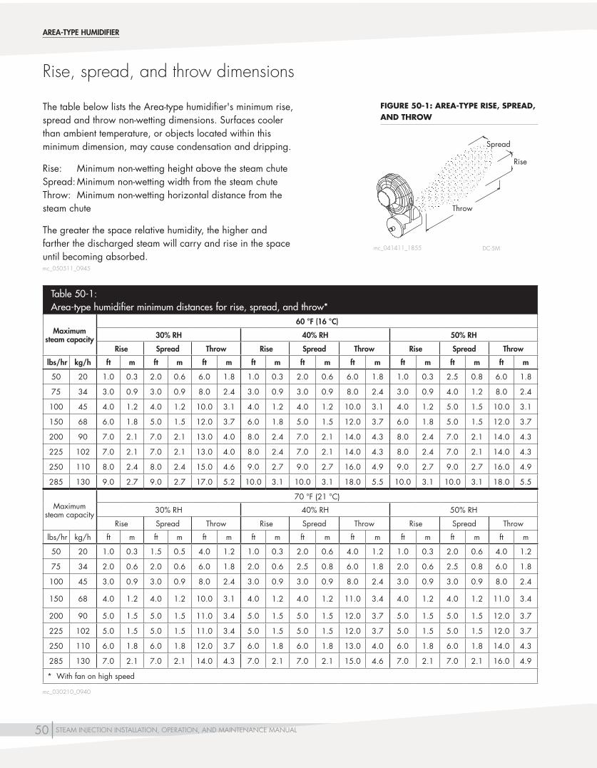
50 STEAM INJECTION INSTALLATION, OPERATION, AND MAINTENANCE MANUAL
The table below lists the Area-type humidifier's minimum rise, spread and throw non-wetting dimensions. Surfaces cooler than ambient temperature, or objects located within this minimum dimension, may cause condensation and dripping.
Rise: Minimum non-wetting height above the steam chute Spread: Minimum non-wetting width from the steam chute Throw: Minimum non-wetting horizontal distance from the steam chute
The greater the space relative humidity, the higher and farther the discharged steam will carry and rise in the space until becoming absorbed.
DC-5M
Rise, spread, and throw dimensions
AREA-TYPE HUMIDIFIER
mc_041411_1855
Table 50-1:Area-type humidifier minimum distances for rise, spread, and throw*
Maximum steam capacity
60 °F (16 °C)
30% RH 40% RH 50% RH
Rise Spread Throw Rise Spread Throw Rise Spread Throw
lbs/hr kg/h ft m ft m ft m ft m ft m ft m ft m ft m ft m
50 20 1.0 0.3 2.0 0.6 6.0 1.8 1.0 0.3 2.0 0.6 6.0 1.8 1.0 0.3 2.5 0.8 6.0 1.8
75 34 3.0 0.9 3.0 0.9 8.0 2.4 3.0 0.9 3.0 0.9 8.0 2.4 3.0 0.9 4.0 1.2 8.0 2.4
100 45 4.0 1.2 4.0 1.2 10.0 3.1 4.0 1.2 4.0 1.2 10.0 3.1 4.0 1.2 5.0 1.5 10.0 3.1
150 68 6.0 1.8 5.0 1.5 12.0 3.7 6.0 1.8 5.0 1.5 12.0 3.7 6.0 1.8 5.0 1.5 12.0 3.7
200 90 7.0 2.1 7.0 2.1 13.0 4.0 8.0 2.4 7.0 2.1 14.0 4.3 8.0 2.4 7.0 2.1 14.0 4.3
225 102 7.0 2.1 7.0 2.1 13.0 4.0 8.0 2.4 7.0 2.1 14.0 4.3 8.0 2.4 7.0 2.1 14.0 4.3
250 110 8.0 2.4 8.0 2.4 15.0 4.6 9.0 2.7 9.0 2.7 16.0 4.9 9.0 2.7 9.0 2.7 16.0 4.9
285 130 9.0 2.7 9.0 2.7 17.0 5.2 10.0 3.1 10.0 3.1 18.0 5.5 10.0 3.1 10.0 3.1 18.0 5.5
Maximum steam capacity
70 °F (21 °C)
30% RH 40% RH 50% RH
Rise Spread Throw Rise Spread Throw Rise Spread Throw
lbs/hr kg/h ft m ft m ft m ft m ft m ft m ft m ft m ft m
50 20 1.0 0.3 1.5 0.5 4.0 1.2 1.0 0.3 2.0 0.6 4.0 1.2 1.0 0.3 2.0 0.6 4.0 1.2
75 34 2.0 0.6 2.0 0.6 6.0 1.8 2.0 0.6 2.5 0.8 6.0 1.8 2.0 0.6 2.5 0.8 6.0 1.8
100 45 3.0 0.9 3.0 0.9 8.0 2.4 3.0 0.9 3.0 0.9 8.0 2.4 3.0 0.9 3.0 0.9 8.0 2.4
150 68 4.0 1.2 4.0 1.2 10.0 3.1 4.0 1.2 4.0 1.2 11.0 3.4 4.0 1.2 4.0 1.2 11.0 3.4
200 90 5.0 1.5 5.0 1.5 11.0 3.4 5.0 1.5 5.0 1.5 12.0 3.7 5.0 1.5 5.0 1.5 12.0 3.7
225 102 5.0 1.5 5.0 1.5 11.0 3.4 5.0 1.5 5.0 1.5 12.0 3.7 5.0 1.5 5.0 1.5 12.0 3.7
250 110 6.0 1.8 6.0 1.8 12.0 3.7 6.0 1.8 6.0 1.8 13.0 4.0 6.0 1.8 6.0 1.8 14.0 4.3
285 130 7.0 2.1 7.0 2.1 14.0 4.3 7.0 2.1 7.0 2.1 15.0 4.6 7.0 2.1 7.0 2.1 16.0 4.9
* With fan on high speed
Rise
Throw
Spread
mc_050511_0945
mc_030210_0940
FIGURE 50-1: AREA-TYPE RISE, SPREAD, AND THROW

51STEAM INJECTION INSTALLATION, OPERATION, AND MAINTENANCE MANUAL
Humidifier start-up and shut-down
OPERATION
HUMIDIFIER START-UP
1. Open steam jacketing shut-off valve, if applicable.
2. Inspect steam valve for proper operation. Pneumatic: Inspect to ensure that: (1) the valve closes off steam tight, (2) the stem packing is not leaking steam, and (3) the diaphragm in the actuator is not leaking air. Electric: Inspect to be sure the valve operates freely, closes off steam tightly, and that the stem packing is not leaking.
3. Inspect steam traps and verify all are working properly. A blocked steam trap will be cold. A “blowing” steam trap will be hot and noisy, and the discharge pipe will be hot for a continuous distance up to 30' (9 m). A properly operating steam trap will have about a two-degree temperature drop measured across the trap from inlet to discharge.
4. Verify airflow proving switch and high limit humidistat, if applicable, are working properly.
HUMIDIFIER SHUT-DOWN
Close humidifier steam supply shut-off valve.
See “Maintenance procedures” on Page 54.

52 STEAM INJECTION INSTALLATION, OPERATION, AND MAINTENANCE MANUAL
Eliminating excess heat from steam jacketed humidifiers
OM-21
Humidifier isolation valve (by others)
Modulating control valve
OPERATION
mc_051011_1630
FIGURE 52-1: SINGLE HUMIDIFYING STEAM PATH

53STEAM INJECTION INSTALLATION, OPERATION, AND MAINTENANCE MANUAL
See Figure 52-1.
In some applications with steam-jacketed humidifiers, the heat given off by the steam-heated tube (not the steams sensible heat) may be undesirable. While relatively insignificant in asingle-tubeunit(usuallyariseoflessthan2°F[1°C]),it can be much greater in a closely-spaced, multiple-tube installation. This can be dealt with in several ways:
1. Manually turn off the steam supply valve after the humidification season.
2. Insulate the tube exterior. Note: Insulation will enlarge the tube profile, causing
additional resistance to airflow.
3. Provide an automatic shut-off valve for the jacketing steam circuit in addition to the modulating control valve. This will eliminate heat gain during the “off” humidification periods only. The jacketing steam valve should be a two-position type, with a minimum Cv of 5, and set to the full-open position prior to opening the modulating valve.
As shown in Figure 52-1, all steam (for jacketing and humidification) must pass through the jacket steam valve. It must do so with little or no pressure drop across the valve, or maximum capacity will be reduced. More importantly, with just one supply source for jacket and humidification steam, the jacket steam temperature may drop below the temperature required to eliminate dripping. Therefore, the valve must be amply sized. This is not significant in a small-capacity humidifier. In a large-capacity humidifier, the required valve size may be quite expensive.
Eliminating excess heat from steam jacketed humidifiers
OPERATION
mc_051011_1631

54 STEAM INJECTION INSTALLATION, OPERATION, AND MAINTENANCE MANUAL
Maintenance procedures
1. Strainer: Inspect the screen at least twice during the first year. If fouled, it should be inspected more frequently and cleaned as needed.
2. Steam trap: At least twice a year, verify that the steam trap is functioning properly. A blocked steam trap will be cold. An improperly operating steam trap with steam exiting the trap will be hot and noisy, and the discharge pipe from it will be hot for a continuous distance up to 30' (9 m). A properly operating steam trap will have about a 2 °F (1 °C) temperature drop measured across the trap from inlet to discharge.
3. Valve (pneumatic): Inspect annually to ensure that: a. The valve tightly closes off steam. b. The stem packing is not leaking steam. c. The diaphragm in the actuator is not leaking air. Valve (electric modulating): Inspect annually to ensure that: a. The valve operates freely. b. The valve tightly closes off steam. c. The stem packing is not leaking steam. Valve (solenoid): Inspect annually to verify proper function with steam-tight shutoff.
4. Silencer: Inspect at least annually for cleanliness. Clean or replace as needed.
5. Teflon seal rings: After one year of service, verify that rings are properly functioning. They require replacement if disturbed, since the Teflon can take a “set” and not return to its uncompressed shape.
6. O-rings (dispersion tube adapters): Replace after two or three years of service.
7. Separator: No maintenance required.
8. Dispersion tube: No maintenance required.
MAINTENANCE

55STEAM INJECTION INSTALLATION, OPERATION, AND MAINTENANCE MANUAL
Table 55-1:Steam Injection troubleshooting guide
Problem Possible cause Action
Humidifier discharges water in duct • Steammainoverloadedwithwaterdue to boiler discharging water with steam (priming) or improper steam main dripping
• Locatecauseofprimingandcorrect
• Steamtrapnotdrainingproperly • Replacetrap,repair,orcleanasrequired• Reducebackpressureofcondensatereturnline
• Steampressureistoolow (below2psi[14kPa])
• Verifythatsteamshutoffvalvesarefullyopen• Adjustpressurereducingvalve• Adjustboilerpressure
• Condensateiscollectinginlow,undripped points in steam main
• Installdripsandsteamtrapsasrequired
• Steamjacketingoftubenotuptoproper temperature
• Excessiveliftingofcondensate.Reroutepipingorraisesteam pressure.
• Shortcircuitinginsidetubejacketing.Replacetube.• Impropersteamtraplocation.Relocateand/oradd
additional trap.• Condensatereturnlinepressureistoohigh.Re-pipe.• Dispersiontubeisnotlevel.Reposition.
• Overloadedcondensatereturnmain • Replacewithlargerpiping,orpipecondensatetofloordrain.
• Inadequatesteamtrapcapacity • Replacesteamtraporificesasnecessary.• Replacewithlargertrap.
Humidifier leaks water • DefectiveO-ringsontubeadapter • ReplaceO-rings
• Steamleakinouterjacketofdispersion tube
• Repairleak,orreplacetube.Note:Checkinstallationtoensure tubes are not rigidly anchored in place. Tubes must be allowed to flex in response to thermal expansion.
Humidity exceeds setting of humidistat
• Automaticvalvenotfullyclosing • Foreignmatterisholdingvalveopen.Cleanvalve;checkline strainer.
• Valvespringisbroken.Replacespring.• Valvestempackingisadjustedtootightly.Loosenand/or
replace packing.• Steampressureexceedsclose-offratingofvalvespring.
Replace actuator or valve spring with one that is compatible with the higher steam pressure.
• Valveisinstalledbackers.Remount.• Adjustvalvelinkage.
• Controlsystemismalfunctioning • Incorrectcontrolvoltage.Verifyandcorrect.• Incorrectcontrolsignal.Verifyandcorrect.• Improperwiring.Verifyandcorrect.• Incorrecthumiditysensor.Verifyandcorrect.• Humiditycontrolleroutofcalibration.Calibrate.
• Leakinsteampipinginsideduct • Repairleak.
Continued
Troubleshooting
TROUBLESHOOTING

56 STEAM INJECTION INSTALLATION, OPERATION, AND MAINTENANCE MANUAL
Table 55-1:Steam Injection troubleshooting guide (continued)
Problem Possible cause Action
Hunting: Humidity swings above and below desired set point
• Controlsystemismalfunctioning. • Faultyorinaccuratehumiditycontroller.Calibrateorreplace.• Poorlocationofcontrolcomponents.Relocate.• Incompatiblecontrolcomponent(s).Changecomponent(s).
• Automaticvalveishunting. • Humidifierisoversized.Changetoasmallervalve.• Pressure-reducingvalveisnotaccuratelycontrollingsteam
pressure. Repair or replace.• Boilerpressureisswingingtoowidely.Adjust.
Space humidity will not rise to humidistat set point
• Excessiveoutsideairvolume • Checkfans,dampers,VAV,etc.
• Steampressureistoolow. • Manualsteamvalveispartiallyclosed.Open.• Strainerscreenispartiallyclogged.Clean.• Boilerpressureistoolow.Adjust.• Pressurereducingvalveisnotaccuratelycontrollingsteam
pressure. Repair or replace.• Boilerpressureisswingingtoowidely.Adjust.• Checkfans,dampers,VAV,etc.• Pipedincorrectly.Re-pipe.• Steampipingisundersized.
• Humidifierisundersized. • Replacevalvewithlargercapacityvalve.• Replacewithlargerhumidifier.• Addadditionalhumidifier.
• Automaticsteamvalveisnotopening fully.
• Valvepackingisadjustedtootightly.Loosenand/orreplacepacking.
• Adjustvalvelinkage.• Checkpilotpositionersettings.
• Controlsystemismalfunctioning. Electric:• Incorrectcontrolcircuitvoltage.Changetransformer.• Incorrectcontrolsignal.Replacecomponent(s)tomakeall
components compatible.• Improperlywired.Rewire.• Incorrecthumiditysensor(Barber-Colmanunitsonly).Replace.• Humiditycontrollerisoutofcalibrationorismalfunctioning.
Repair or replace.• Malfunctioninghumidifiertemperatureswitchisnotallowing
humidifier valve to open. Replace or readjust.Pneumatic:• Humiditycontrollerisoutofcalibrationorismalfunctioning.
Repair or replace.• Obstructedairline.Clean.• Malfunctioningpneumatictemperatureswitch.Replace.• Airleakinactuator.Repairorreplace.• Compressedairpressureistoolow.Adjust.
Continued
Troubleshooting
TROUBLESHOOTING

57STEAM INJECTION INSTALLATION, OPERATION, AND MAINTENANCE MANUAL
Table 55-1:Steam Injection troubleshooting guide (continued)
Problem Possible cause Action
Space humidity will not rise to humidistat set point(continued)
• Foreignmatterispreventingvalvefrom opening.
• Cleanorreplacevalve.
• Excessiveoutsideairvolume. • Reduceairvolume.
Condensate in duct • Humidifierismountedtooclosetointernal devices (dampers, turning vanes, etc.) in duct.
• Checkfan,dampers,VAV,etc.• Movehumidifiertubestoapointfartherupstreamfrom
internal devices.• Adddispersiontubesforshorterabsorptiondistance.consult
DriSteem to determine the total number of tubes required.
• Anoninsulatedductispassingthrough an unheated area (duct surface temperature is too low).
• Insulateductwork.
• Aircannotabsorbsteamquantitybeing discharged.
• Humidifierisoperatingwhenblowerisoff.Installairflowproving switch.
• Valveishunting.Seepreviouspageforinstructions.• Airtemperatureinductistoolowforsteamquantitybeing
supplied. • Aircfminductistoolowforsteamquantitybeingsupplied.
• Steampressureistoohigh,causingexcess capacity.
• Reducesteampressure.
Humidifier is noisy • Tubesilencerismissing. • Installsilencer.
Note: Unless special-ordered, silencers are furnished only with Model 60 and Model 70 tubes equal to or shorter than 48” (1219 mm), and only with black iron piping.
• Dispersiontubeoutputisexcessivelyhigh.
• Installadditionaltubes.
Troubleshooting
TROUBLESHOOTING
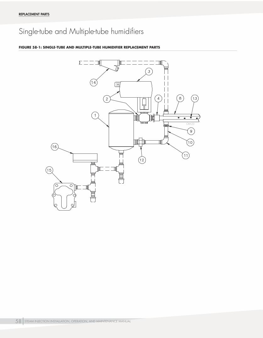
58 STEAM INJECTION INSTALLATION, OPERATION, AND MAINTENANCE MANUAL
Single-tube and Multiple-tube humidifiers
OM-23
REPLACEMENT PARTS
FIGURE 58-1: SINGLE-TUBE AND MULTIPLE-TUBE HUMIDIFIER REPLACEMENT PARTS

59STEAM INJECTION INSTALLATION, OPERATION, AND MAINTENANCE MANUAL
Single-tube and Multiple-tube humidifiers
REPLACEMENT PARTS
Table 59-1: Single-tube and Multiple-tube humidifier replacement parts
No . Description Part No .
1 Separator (vertical separator shown) Consult factory
2Valve/actuator assembly (refer to specific order)Valve/actuator assembly or actuator alone are available as replacement parts. Valve body alone is not available as a replacement part.
Consult factory
3 Actuator Consult factory
4 Tube adapter Consult factory
5
O-ring,1"I.D.,blackEPDM,forModel60andModel70tubes (not shown) 300400-007
O-ring, 1½” I.D., black EPDM, for Model 80 tubes (not shown) 300400-006
6 Silencer holder, stainless steel (not shown) 183100
7 Medium grit stainless steel wool (not shown) 300210
8 Replacement tube Consult factory
9
Sealring,brass,1/2"(DN15),forModel60tube 306360-001
Sealring,brass,3/4"(DN20),forModel70tube 306360-002
Sealring,brass,1½"(DN40),forModel80tube 306360-003
Sealring,316stainlesssteel,1/2"(DN15),forModel60tube 306360-007
Sealring,316stainlesssteel,3/4"(DN20),forModel70tube 306360-004
Sealring,316stainlesssteel,1½"(DN40),forModel80tube 306360-006
10 Nipple Consult factory
11 Elbow Consult factory
12 Union Consult factory
13 Tubelet Consult factory
14 Y-strainer Consult factory
15
Steam trap, float and thermostatic (F&T) (shown), cast iron, 3/4"(DN20),for≤15psi(103.4kPa) 300000-DB
Steam trap, inverted bucket, cast iron, 3/4"(DN20),for>15psi(103.4kPa)orliftingcondensate 300010
Steamtrap,thermostatic,316stainlesssteel,3/4"(DN20) 300025
16Temperature switch, electric 400260-001
Temperature switch, pneumatic 307076

60 STEAM INJECTION INSTALLATION, OPERATION, AND MAINTENANCE MANUAL
Table 60-1: Area-type humidifier with electric fan replacement parts
No . Description Part No .
1 Separator(with3/4"NPT[DN20]supply) Consult factory
2 Fan, three-speed 400010
3 Valve actuator Consult factory
4
Valve,1/2"NPT(DN15)pneumaticwithoperator 510060
Valve,3/4"NPT(DN20)pneumaticwithoperator 510061
Valve,1"NPT(DN25)pneumaticwithoperator 510063
Valve,1/2"NPT(DN15)electric 510030
Valve,3/4"NPT(DN20)electric 510031
Valve,1"NPT(DN25)electric 510032
Area-type humidifier
13
2
4
REPLACEMENT PARTS
FIGURE 60-1: AREA-TYPE HUMIDIFIER WITH ELECTRIC FAN
DC-6M

61STEAM INJECTION INSTALLATION, OPERATION, AND MAINTENANCE MANUAL
Table 61-1: Mini-bank humidifier replacement parts
No . Description Part No .
1 5"(127mm)separator 162520
2Valve,1/2"(DN15))pneumaticwithoperator 510060
Valve,1/2"(DN15)electric 510030
3 Orifice, brass (not shown)* 203450
4 Trap, float and thermostatic (F&T) (not shown)** 300000
5 Y-strainer,1/2"(DN15)(notshown)** 300100-001
6 Valve actuator Consult factory
NOTES:* Varies with each order** Shipped loose
OM-7479
Mini-bank humidifier
6
1
2
REPLACEMENT PARTS
FIGURE 61-1: MINI-BANK HUMIDIFIER REPLACEMENT PARTS

Form No. DS-IOM-0115Part No. 890000-401 Rev F
Two-year Limited WarrantyDRI-STEEM Corporation (“DriSteem”) warrants to the original user that its products will be free from defects in materials and workmanship for a period of two (2) years after installation or twenty-seven (27) months from the date DriSteem ships such product, whichever date is the earlier.
If any DriSteem product is found to be defective in material or workmanship during the applicable warranty period, DriSteem’s entire liability, and the purchaser’s sole and exclusive remedy, shall be the repair or replacement of the defective product, or the refund of the purchase price, at DriSteem’s election. DriSteem shall not be liable for any costs or expenses, whether direct or indirect, associated with the installation, removal or reinstallation of any defective product. The Limited Warranty does not include cylinder replacement for electrode steam humidifiers.
DriSteem’s Limited Warranty shall not be effective or actionable unless there is compliance with all installation and operating instructions furnished by DriSteem, or if the products have been modified or altered without the written consent of DriSteem, or if such products have been subject to accident, misuse, mishandling, tampering, negligence or improper maintenance. Any warranty claim must be submitted to DriSteem in writing within the stated warranty period. Defective parts may be required to be returned to DriSteem.
DriSteem’s Limited Warranty is made in lieu of, and DriSteem disclaims all other warranties, whether express or implied, including but not limited to any IMPLIED WARRANTY OF MERCHANTABILITY, ANY IMPLIED WARRANTY OF FITNESS FOR A PARTICULAR PURPOSE, any implied warranty arising out of a course of dealing or of performance, custom or usage of trade.
DriSteem SHALL NOT, UNDER ANY CIRCUMSTANCES BE LIABLE FOR ANY DIRECT, INDIRECT, INCIDENTAL, SPECIAL OR CONSEQUENTIAL DAMAGES (INCLUDING, BUT NOT LIMITED TO, LOSS OF PROFITS, REVENUE OR BUSINESS) OR DAMAGE OR INJURY TO PERSONS OR PROPERTY IN ANY WAY RELATED TO THE MANUFACTURE OR THE USE OF ITS PRODUCTS. The exclusion applies regardless of whether such damages are sought based on breach of warranty, breach of contract, negligence, strict liability in tort, or any other legal theory, even if DriSteem has notice of the possibility of such damages.
By purchasing DriSteem’s products, the purchaser agrees to the terms and conditions of this Limited Warranty.
Extended warrantyThe original user may extend the term of the DriSteem Limited Warranty for a limited number of months past the initial applicable warranty period and term provided in the first paragraph of this Limited Warranty. All the terms and conditions of the Limited Warranty during the initial applicable warranty period and term shall apply during any extended term. An extended warranty term of an additional twelve (12) months or twenty four (24) months of coverage may be purchased. The extended warranty term may be purchased until eighteen (18) months after the product is shipped, after which time no extended warranties are available.
Any extension of the Limited Warranty under this program must be in writing, signed by DriSteem, and paid for in full by the purchaser.mc_051308_0630
DRI-STEEM Corporation a subsidiary of Research Products Corporation DriSteem is an ISO 9001:2000 certified company
U.S. Headquarters:14949 Technology DriveEden Prairie, MN 55344800-328-4447 or 952-949-2415952-229-3200 (fax)
European office:Marc Briers Grote Hellekensstraat 54 b B-3520 Zonhoven Belgium +3211823595 (voice) +3211817948 (fax) E-mail: [email protected]
Continuous product improvement is a policy of DriSteem Corporation; therefore, product features and specifications are subject to change without notice. DriSteem, DriCalc and Mini-bank are registered trademarks of Research Products Corporation and are filed for trademark registration in Canada and the European community. Area-type and Maxi-bank and trademarks of Research Products Corporation. Product and corporate names used in this document may be trademarks or registered trademarks. They are used for explanation only without intent to infringe.
© 2015 Research Products Corporation
Expect quality from the industry leader
For more than 45 years, DriSteem has been leading the industry with creative and reliable humidification solutions. Our focus on quality is evident in the construction of our Steam Injection humidifiers, which feature cleanable stainless steel construction. DriSteem also leads the industry with a Two-year Limited Warranty and optional extended warranty.
For more informationwww.dristeem.com [email protected]
For the most recent product information visit our Web site: www.dristeem.com
WARRANTY