Type 20 and Type 40 Direct Steam Injection (SI) Humidifiers
24
1. Safety information 2. General product information 3. Installation 4. Commissioning 5. Maintenance and spare parts 6. Troubleshooting © Copyright 2020 Printed in GB 7950050/5 Type 20 and Type 40 Direct Steam Injection (SI) Humidifiers Installation and Maintenance Instructions IM-P795-04 CMGT Issue 5
Transcript of Type 20 and Type 40 Direct Steam Injection (SI) Humidifiers

IM-P795-04 CMGT Issue 5 1
Type 20 and Type 40 Direct Steam Injection (SI) Humidifiers
1. Safety information
2. General product information
3. Installation
4. Commissioning
5. Maintenance and spare parts
6. Troubleshooting
© Copyright 2020
Printed in GB
7950050/5
Type 20 and Type 40Direct Steam Injection (SI) Humidifiers
Installation and Maintenance Instructions
IM-P795-04CMGT Issue 5

IM-P795-04 CMGT Issue 52
Type 20 and Type 40 Direct Steam Injection (SI) Humidifiers

IM-P795-04 CMGT Issue 5 3
Type 20 and Type 40 Direct Steam Injection (SI) Humidifiers
Safe operation of these products can only be guaranteed if they are properly installed, commissioned, used and maintained by qualified personnel (see Section 1.11) in compliance with the operating instructions. General installation and safetyinstructions for pipeline and plant construction, as well as the proper use of tools and safety equipment must also be complied with.
1.1 Intended useReferring to the Installation and Maintenance Instructions, name-plate and Technical Information Sheet, check that the product is suitable for the intended use/application. The products comply with the requirements of the Pressure Equipment Directive 2014/68/EU and fall within category 'SEP'. It should be noted that products within this category are required by the directive not to carry the mark.
i) The products have been specifically designed for use on steam and water, which are in Group 2 of the above mentioned Pressure Equipment Directive. The products’ use on other fluids may be possible but, if this is contemplated, Spirax Sarco should be contacted to confirm the suitability of the product for the application being considered.
ii) Check material suitability, pressure and temperature and their maximum and minimum values. If the maximum operating limits of the product are lower than those of the system in which it is being fitted, or if malfunction of the product could result in a dangerous overpressure or overtemperature occurrence, ensure a safety device is included in the system to prevent such over-limit situations.
iii) Determine the correct installation situation and direction of fluid flow.
iv) Spirax Sarco products are not intended to withstand external stresses that may be induced by any system to which they are fitted. It is the responsibility of the installer to consider these stresses and take adequate precautions to minimise them.
v) Remove protection covers from all connections before installation.
1.2 AccessEnsure safe access and if necessary a safe working platform (suitably guarded) before attempting to work on the product. Arrange suitable lifting gear if required.
1.3 LightingEnsure adequate lighting, particularly where detailed or intricate work is required.
1.4 Hazardous liquids or gases in the pipelineConsider what is in the pipeline or what may have been in the pipeline at some previous time. Consider: flammable materials, substances hazardous to health, extremes of temperature.
1.5 Hazardous environment around the productConsider: explosion risk areas, lack of oxygen (e.g. tanks, pits), dangerous gases, extremes of temperature, hot surfaces, fire hazard (e.g. during welding), excessive noise, moving machinery.
1. Safety information
IM-P795-04 CMGT Issue 54
Type 20 and Type 40 Direct Steam Injection (SI) Humidifiers
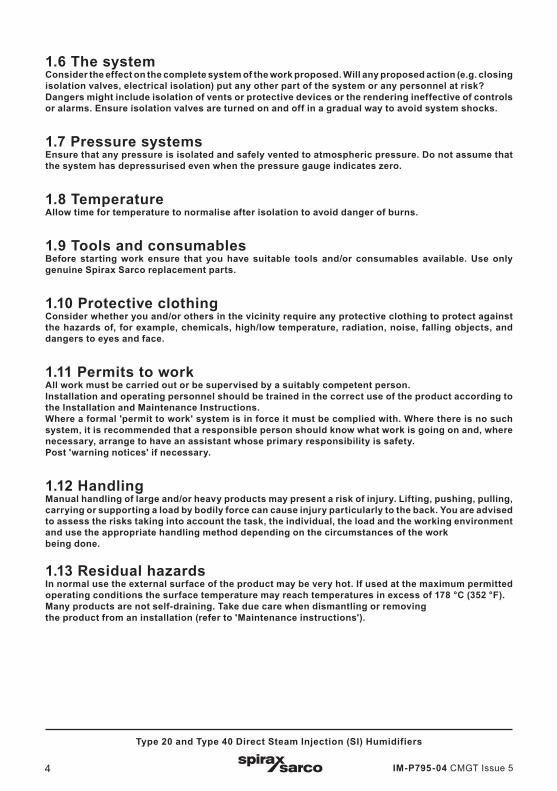
1.6 The systemConsider the effect on the complete system of the work proposed. Will any proposed action (e.g. closing isolation valves, electrical isolation) put any other part of the system or any personnel at risk? Dangers might include isolation of vents or protective devices or the rendering ineffective of controls or alarms. Ensure isolation valves are turned on and off in a gradual way to avoid system shocks.
1.7 Pressure systems Ensure that any pressure is isolated and safely vented to atmospheric pressure. Do not assume that the system has depressurised even when the pressure gauge indicates zero.
1.8 TemperatureAllow time for temperature to normalise after isolation to avoid danger of burns.
1.9 Tools and consumablesBefore starting work ensure that you have suitable tools and/or consumables available. Use only genuine Spirax Sarco replacement parts.
1.10 Protective clothingConsider whether you and/or others in the vicinity require any protective clothing to protect against the hazards of, for example, chemicals, high/low temperature, radiation, noise, falling objects, and dangers to eyes and face.
1.11 Permits to workAll work must be carried out or be supervised by a suitably competent person.Installation and operating personnel should be trained in the correct use of the product according to the Installation and Maintenance Instructions.Where a formal 'permit to work' system is in force it must be complied with. Where there is no such system, it is recommended that a responsible person should know what work is going on and, where necessary, arrange to have an assistant whose primary responsibility is safety.Post 'warning notices' if necessary.
1.12 HandlingManual handling of large and/or heavy products may present a risk of injury. Lifting, pushing, pulling, carrying or supporting a load by bodily force can cause injury particularly to the back. You are advised to assess the risks taking into account the task, the individual, the load and the working environment and use the appropriate handling method depending on the circumstances of the workbeing done.
1.13 Residual hazardsIn normal use the external surface of the product may be very hot. If used at the maximum permitted operating conditions the surface temperature may reach temperatures in excess of 178 °C (352 °F).Many products are not self-draining. Take due care when dismantling or removing the product from an installation (refer to 'Maintenance instructions').
IM-P795-04 CMGT Issue 5 5
Type 20 and Type 40 Direct Steam Injection (SI) Humidifiers
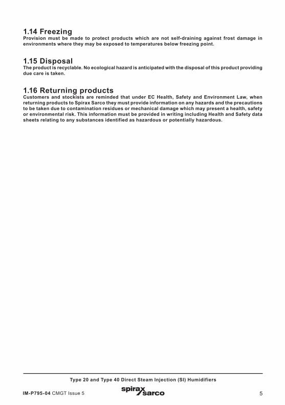
1.14 FreezingProvision must be made to protect products which are not self-draining against frost damage in environments where they may be exposed to temperatures below freezing point.
1.15 DisposalThe product is recyclable. No ecological hazard is anticipated with the disposal of this product providing due care is taken.
1.16 Returning productsCustomers and stockists are reminded that under EC Health, Safety and Environment Law, when returning products to Spirax Sarco they must provide information on any hazards and the precautions to be taken due to contamination residues or mechanical damage which may present a health, safety or environmental risk. This information must be provided in writing including Health and Safety data sheets relating to any substances identified as hazardous or potentially hazardous.
IM-P795-04 CMGT Issue 56
Type 20 and Type 40 Direct Steam Injection (SI) Humidifiers
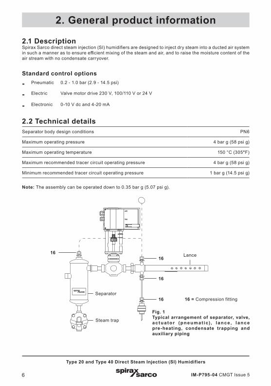
2.1 DescriptionSpirax Sarco direct steam injection (SI) humidifiers are designed to inject dry steam into a ducted air system in such a manner as to ensure efficient mixing of the steam and air, and to raise the moisture content of the air stream with no condensate carryover.
Standard control options
- Pneumatic 0.2 - 1.0 bar (2.9 - 14.5 psi)
- Electric Valve motor drive 230 V, 100/110 V or 24 V
- Electronic 0-10 V dc and 4-20 mA
2.2 Technical detailsSeparator body design conditions PN6
Maximum operating pressure 4 bar g (58 psi g)
Maximum operating temperature 150 °C (305°F)
Maximum recommended tracer circuit operating pressure 4 bar g (58 psi g)
Minimum recommended tracer circuit operating pressure 1 bar g (14.5 psi g)
Note: The assembly can be operated down to 0.35 bar g (5.07 psi g).
2. General product information
Fig. 1Typical arrangement of separator, valve, ac t u a to r (p n eu m a t i c) , l a n c e , l a n c e pre-heating, condensate trapping and auxiliary piping
16
16 = Compression fitting
16
16
Lance
Separator
Steam trap
16

IM-P795-04 CMGT Issue 5 7
Type 20 and Type 40 Direct Steam Injection (SI) Humidifiers
2.3 Indentification (see Figure 2)The label on the separator indicates the system Type (20 or 40) and the maximum operating pressure - 400 kPa (58 psi g).The label on the Lance shows the Type (20 or 40) and the Model (1 - 12).
2.4 System
Typical date code
Fig. 2.
The Spirax Sarco SI humidifier system comprises 4 basic elements:
- The separator and pipework components (to suit valve type to be installed)
- Control valve and actuator (these may be of Spirax Sarco manufacture, or from other proprietary producers. Spirax Sarco would supply the relevant Installation and Maintenance Instructions).
- Lance(s).
- Ancillaries.
Note: Certain items of pipework and fittings are to be supplied by the customer or installer.
2.5 Supply and packagingThe packing method used with Spirax Sarco humidifiers will vary with the Type and Model supplied. It is important to check the equipment against the order / acknowledgement. Separators carry a label giving Type (20 or 40). The lance label will show Type (20 or 40) and Model Code (1 - 12: see the Technical Information (TI) for the equivalent lance length). Associated equipment, such as steam traps, strainers, pressure reducing stations etc., which may be part of the order, will be packed separately. Where Spirax Sarco supply the valve (any make), it will be already connected to the separator outlet using the appropriate fittings. Any additional piping components will be supplied separately packaged. There are two compression fittings (16 - see Figure 1) supplied with the separator and a further two with each lance. Lances are supplied in a rigid cardboard tube.

IM-P795-04 CMGT Issue 58
Type 20 and Type 40 Direct Steam Injection (SI) Humidifiers
3.1 Equipment provided
3.1.1 Unpack individual packages in the area where the installation is to take place. This avoids the possible loss or damage to parts in transit over the site.
3.1.2 Items shown dotted are to be supplied by the installer.
3.1.3 Two ¼" BSP x 8 mm compression fittings (16 - see Figure 1) are supplied with each separator, and two with each lance. These support the tracer heating pipework between the steam supply (separator or separate source) and the lance(s), and the discharge from the tracer heating circuit to the trap.
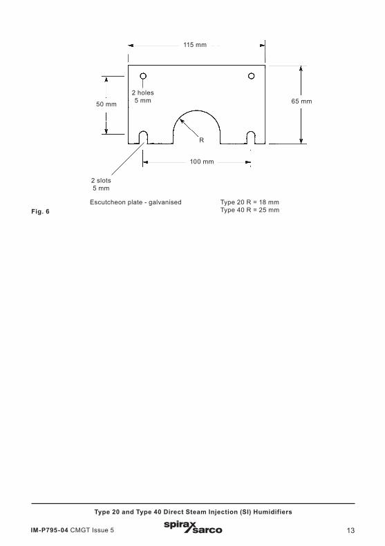
3.1.4 If escutcheon plates are to be used (see Figure 6, page 11).
3.1.5 The installer is responsible for the main lance steam supply / supporting pipework.
3.1.6 As the tracer heating circuit is parallel to, but independent from, the main lance steam supply, it can be run in any acceptable material. Spirax Sarco are able to supply 8 mm annealed copper for this purpose.
3.2 Lance, tracer and pre-heating circuit3.2.1 The main inlet connection on the lance is: Type 20 - ¾" screwed Type 40 - 1½" screwed
The two tracer connections on each lance are ¼" BSP.
3.2.2 A single lance can be connected directly to the outlet of the valve using the piping components provided (see Figures 7 to 10, page 12). These are supplied to match the flanged or screwed connections of the valve to be installed, when the valve is ordered.
3.2.3 The connection of the lance to the separator with these fittings, allows the correct orientation of the lance to be achieved, i.e. nozzles facing into the air flow (except for the installation shown in Figure 15, page 14). This is important to consider as the lance(s) can be inserted from either the left hand side or the right hand side of the duct.
3.2.4 If the tracer heating steam is taken from the top connection on the separator, then the pressure/temperature of the tracer circuit will be as for the main humidifying steam supply. Where dry steam is sourced from a separate system for tracer heating, the top connection on the separator (¼" BSP) should be plugged. The tracer heating circuit can operate at up to 4 bar g (58 psi g) steam pressure.
3.2.5 Single lance systems should be assembled such that the lance is mid-height in the duct.
3.2.6 On multi-lance systems, the lances should be assembled such that there is an even distribution of steam over the duct, as shown in Figure 3, page 10. Particular attention should be paid to the position of the main steam supply to the interconnecting pipework - see Figures 5, 11, 12 and 13.Generally up to 5 lances can be installed horizontally on an application.Recommendations on lance numbers relative to duct height can be found in Section 3.3.4.
3.2.7 The outer end of the lance can be supported utilising the M10 thread in the lance end cap.
3. Installation

IM-P795-04 CMGT Issue 5 9
Type 20 and Type 40 Direct Steam Injection (SI) Humidifiers
3.3 Installation and pipe sizing3.3.1 Ensure that the main steam supply system, where pressure reduction is required, is installed correctly
to provide the driest possible steam. Details will be found in Section 3.9. The maximum steam pressure to the separator must not exceed 4 bar g (58 psi g).
3.3.2 A section of the steam supply end of the lance will protrude through the side of the duct. Sufficient length must be provided to allow for the tracer heating and condensate pipe connections, and the required thickness of lagging.To accept the lance, a hole to suit the lance diameters must be provided in the duct wall, as follows:Type 20 Lance - 38 mm diameter - minimum.Type 40 Lance - 54 mm diameter - minimum.The small clearance between the duct and the lance can be sealed either with a proprietary high temperature mastic, or by use of the Type 20 or Type 40 escutcheon plates - see Figure 6, page 11.
3.3.3 To assist in ensuring that there are no problems with steam condensing in the duct and to obtain minimum absorption distance, the lance(s) should be positioned as shown in Figure 3, page 10.
3.3.4 The recommendations on the number of lances for various duct heights are:
Duct height: Number of lances
Up to 1000 mm 1
1000 - 1700 mm 2
1700 - 2200 mm 3
2200 - 2600 mm 4
2600 mm and over 5
3.3.5 Figures 7 to 10, page 12 give details of the piping components supplied as standard with Spirax Sarco humidifiers.
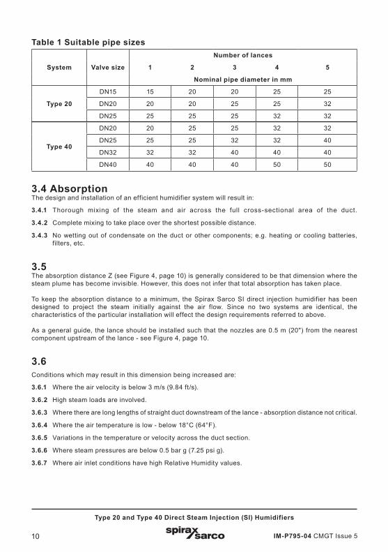
3.3.6 Table 1 indicates suitable pipe sizes to maintain the correct steam flow to the lance(s) without creating excessive pipework pressure loss between the control valve outlet and the lance inlet.
3.3.7 Wherever possible, all interconnecting pipework, valves, separators etc, should be adequately lagged. This will reduce heat (energy) losses, and allow quicker warm-up time, reduce the amount of condensate produced and generally improve the overall efficiency of the installation.
3.3.8 Figures 11, 12 and 13, page 13, give recommendations for piping up the main steam supply, trapping arrangements and manifolding for a variety of multi-lance and vertical lance installations.
IM-P795-04 CMGT Issue 510
Type 20 and Type 40 Direct Steam Injection (SI) Humidifiers
Table 1 Suitable pipe sizes
System Valve size
Number of lances
1 2 3 4 5
Nominal pipe diameter in mm
Type 20
DN15 15 20 20 25 25
DN20 20 20 25 25 32
DN25 25 25 25 32 32
Type 40
DN20 20 25 25 32 32
DN25 25 25 32 32 40
DN32 32 32 40 40 40
DN40 40 40 40 50 50
3.4 AbsorptionThe design and installation of an efficient humidifier system will result in:
3.4.1 Thorough mixing of the steam and air across the full cross-sectional area of the duct.
3.4.2 Complete mixing to take place over the shortest possible distance.
3.4.3 No wetting out of condensate on the duct or other components; e.g. heating or cooling batteries, filters, etc.
3.5The absorption distance Z (see Figure 4, page 10) is generally considered to be that dimension where the steam plume has become invisible. However, this does not infer that total absorption has taken place.
To keep the absorption distance to a minimum, the Spirax Sarco SI direct injection humidifier has been designed to project the steam initially against the air flow. Since no two systems are identical, the characteristics of the particular installation will effect the design requirements referred to above.
As a general guide, the lance should be installed such that the nozzles are 0.5 m (20") from the nearest component upstream of the lance - see Figure 4, page 10.
3.6Conditions which may result in this dimension being increased are:
3.6.1 Where the air velocity is below 3 m/s (9.84 ft/s).
3.6.2 High steam loads are involved.
3.6.3 Where there are long lengths of straight duct downstream of the lance - absorption distance not critical.
3.6.4 Where the air temperature is low - below 18°C (64°F).
3.6.5 Variations in the temperature or velocity across the duct section.
3.6.6 Where steam pressures are below 0.5 bar g (7.25 psi g).
3.6.7 Where air inlet conditions have high Relative Humidity values.

IM-P795-04 CMGT Issue 5 11
Type 20 and Type 40 Direct Steam Injection (SI) Humidifiers
3.7Conditions which may result in this dimension being increased are:
3.7.1 Low steam loads.
3.7.2 Where the steam pressure (temperature) at the main control valve inlet is high.
3.7.3 With high air velocity.
3.7.4 If the air temperature off the heater battery is high - over 25°C (77°F).
3.7.5 Where a small amount of wetting out is permissible.
3.7.6 Where incoming air Relative Humidity levels are low.
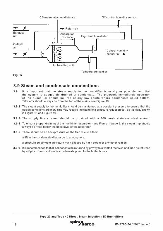
3.8Humidity and temperature sensors should be installed at a sufficient distance downstream to ensure full mixing of the air and steam to obtain true readings (see Figure 4).High limit humidistats, typical set at 90% Relative Humidity, would normally be installed 2 to 3 m (6.5 to 10 ft) downstream of the humidifier. This control is to prevent any over-saturation of the system due to a failure or malfunction of the main control humidistat.In open area humidification from a duct supply, the main control humidity sensor would be fitted in the open area (see 'C' in Figure 17, page 15).With installations incorporating return air systems, the main control humidity sensor would generally be fitted in the return air duct (See Figure 17, page 15).
X
X
YH
2 lancesX = H/4
Y = H/2
3 lancesX = H/6
Y = H/3
4 lancesX = H/8
Y = H/4
5 lancesX = H/10
Y = H/5
Fig. 3
Lance
Lance
Duct

IM-P795-04 CMGT Issue 512
Type 20 and Type 40 Direct Steam Injection (SI) Humidifiers
Fig. 4
Duct pressure stat
High limit
humidistat
Absorption distance
0.5 m
Air flow
Fan
Humidifier lance
Heater battery
Z
Controllinghumiditysensor
2Z - 3Z 5Z - 6Z
Fig. 5Alternative separate steam supply for pre-heater - maximum 4 bar g (58 psi g)Parts shown in dotted line - Customer to supply.
Duct wallInsulation
Escutcheun plate
IM-P795-04 CMGT Issue 5 13
Type 20 and Type 40 Direct Steam Injection (SI) Humidifiers
115 mm
100 mm
R
65 mm50 mm
2 holes 5 mm
Escutcheon plate - galvanised Type 20 R = 18 mm Type 40 R = 25 mmFig. 6
2 slots 5 mm

IM-P795-04 CMGT Issue 514
Type 20 and Type 40 Direct Steam Injection (SI) Humidifiers
Fig. 7Type 20 screwed
Fig. 8Flanged PN16 EN 1092
DN20
DN25
DN15
DN15
DN20
DN25
The appropriate piping components will be supplied with each humidifier to match the valve supplied, or valve to be fitted. Where a valve is not supplied the pipe fittings used between the separator and the valve will be fitted to the separator outlet pipe. Flanged sets are supplied complete with gaskets, nuts and bolts. Any components not supplied fitted will be supplied bagged.
Fig. 10Flanged PN16 EN 1092
Fig. 9Type 40 screwed
DN40
DN32
DN25
DN20
DN40
DN32
DN25
DN20

IM-P795-04 CMGT Issue 5 15
Type 20 and Type 40 Direct Steam Injection (SI) Humidifiers
Fig. 11Multi-lance installation where lances are of reasonable length and where a single tracer trap is appropriate.
Fig. 12Multi-Lance installation with long lances such that a split tracer is required.
For sizingsee Table 1, page 8
➤➤

IM-P795-04 CMGT Issue 516
Type 20 and Type 40 Direct Steam Injection (SI) Humidifiers
Fig. 13 Vertical multi-lance system where separate steam supply and condensate headers, suitably trapped, are needed. For more detailed information or assistance with this type of installation, please contact your local Spirax Sarco engineer, or Spirax Sarco branch office.
Fig. 14Horizontal duct - Horizontal lance
Air flow
Plan

IM-P795-04 CMGT Issue 5 17
Type 20 and Type 40 Direct Steam Injection (SI) Humidifiers
Fig. 15Horizontal duct - Vertical lance
Air flow
Plan
Air flow
Plan
Fig. 16Vertical duct - Horizontal lance
IM-P795-04 CMGT Issue 518
Type 20 and Type 40 Direct Steam Injection (SI) Humidifiers
Fig. 17
Air handling unit
Exhaustair
Outsideair
Return air
Absorption distance
Control humidity sensor 'C '
Temperature sensor
High limit humidistat
'C ' control humidity sensor0.5 metre injection distance
3.9 Steam and condensate connections3.9.1 It is impor tant that the steam supply to the humidif ier is as dry as possible, and that
the system is adequately drained of condensate. The pipework immediately upstream of the humidi f ier should be f ree of any low points where condensate could col lect .Take offs should always be from the top of the main - see Figure 18.
3.9.2 The steam supply to the humidifier should be maintained at a constant pressure to ensure that the design conditions are met. This may require the fitting of a pressure reduction set, as typically shown in Figure 18 and Figure 19.
3.9.3 The supply l ine strainer should be provided with a 100 mesh stainless steel screen.
3.9.4 To ensure proper draining of the humidifier separator - see Figure 1, page 5, the steam trap should always be fitted below the base level of the separator.
3.9.5 There should be no backpressure on the trap due to either:
a lift in the condensate discharge to atmosphere,
a pressurised condensate return main caused by flash steam or any other reason
3.9.6 It is recommended that all condensate be returned by gravity to a vented receiver, and then be returned by a Spirax Sarco automatic condensate pump to the boiler house.

IM-P795-04 CMGT Issue 5 19
Type 20 and Type 40 Direct Steam Injection (SI) Humidifiers
Fig. 19Pressure reducing valve set up including mains separator, isolating valves, condensate trap sets and safety valve. The arrangement is based upon the use of a Spirax Sarco DP pressure reducing valve.
To humidifier
Fig. 18Pressure reducing station where the mains steam is dry, steam flows are low and for less critical pressure applications. The arrangement is based upon the use of a Spirax Sarco BRV2 pressure reducing valve.
To humidifier

IM-P795-04 CMGT Issue 520
Type 20 and Type 40 Direct Steam Injection (SI) Humidifiers
3.10 Control air for pneumatic actuatorsWhen valves and actuators are supplied, full manufacturer’s installation and commissioning instructions are included. Purchasers must ensure that these specialist products are fully compatible with any other control elements supplied by others.
3.10.1 The air supply must be dry, clean and free from oil contamination. This is particularly important where a pneumatic positioner is used.
3.10.2 The humidity sensor must be installed in accordance with the manufacturers recommendations.
3.10.3 Interlocks for system shutdown are recommended between the humidifier, fans, humidistat, duct pressure stat or high limit humidistat.
3.10.4 Figure 20 shows a typical pneumatic control system, incorporating a positioner.
Fig. 20Typical pneumatic control valve with positioner
Air supply2 to 6 bar
Filterregulator
EP positioner
4 to 20 mA
Controller
4 to 20 mA
Relative Humidity duct sensor
24 V
IM-P795-04 CMGT Issue 5 21
Type 20 and Type 40 Direct Steam Injection (SI) Humidifiers
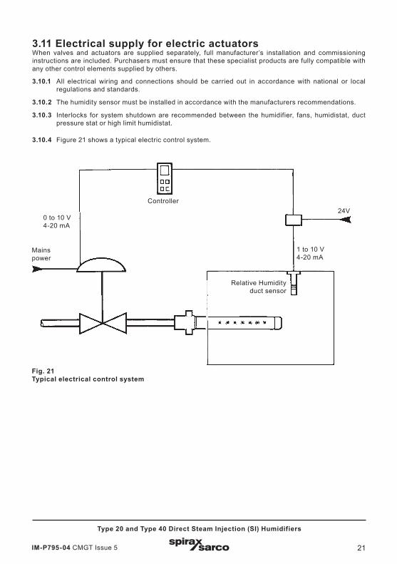
3.11 Electrical supply for electric actuatorsWhen valves and actuators are supplied separately, full manufacturer’s installation and commissioning instructions are included. Purchasers must ensure that these specialist products are fully compatible with any other control elements supplied by others.
3.10.1 All electrical wiring and connections should be carried out in accordance with national or local regulations and standards.
3.10.2 The humidity sensor must be installed in accordance with the manufacturers recommendations.
3.10.3 Interlocks for system shutdown are recommended between the humidifier, fans, humidistat, duct pressure stat or high limit humidistat.
3.10.4 Figure 21 shows a typical electric control system.
Fig. 21Typical electrical control system
0 to 10 V4-20 mA
Controller24V
1 to 10 V4-20 mA
Mainspower
Relative Humidityduct sensor
IM-P795-04 CMGT Issue 522
Type 20 and Type 40 Direct Steam Injection (SI) Humidifiers
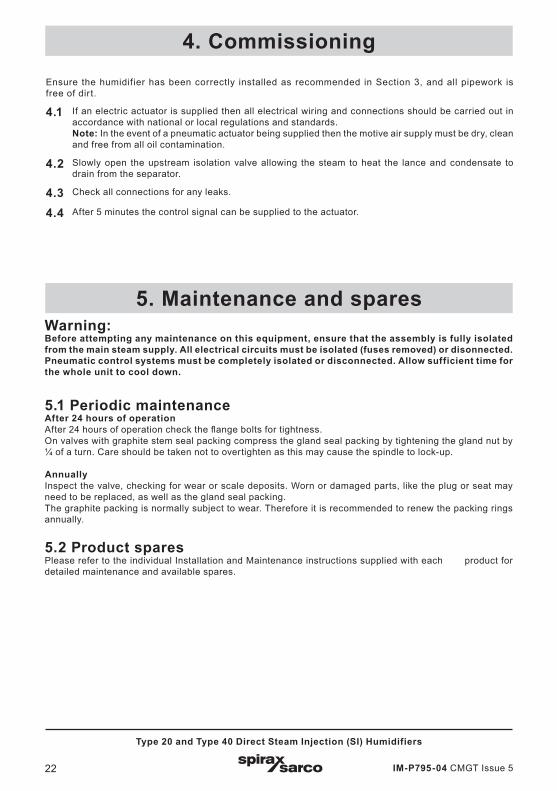
Ensure the humidifier has been correctly installed as recommended in Section 3, and all pipework is free of dirt.
4.1 If an electric actuator is supplied then all electrical wiring and connections should be carried out in accordance with national or local regulations and standards.Note: In the event of a pneumatic actuator being supplied then the motive air supply must be dry, clean and free from all oil contamination.
4.2 Slowly open the upstream isolation valve allowing the steam to heat the lance and condensate to drain from the separator.
4.3 Check all connections for any leaks.
4.4 After 5 minutes the control signal can be supplied to the actuator.
4. Commissioning
5. Maintenance and sparesWarning:Before attempting any maintenance on this equipment, ensure that the assembly is fully isolated from the main steam supply. All electrical circuits must be isolated (fuses removed) or disonnected. Pneumatic control systems must be completely isolated or disconnected. Allow sufficient time for the whole unit to cool down.
5.1 Periodic maintenanceAfter 24 hours of operationAfter 24 hours of operation check the flange bolts for tightness.On valves with graphite stem seal packing compress the gland seal packing by tightening the gland nut by ¼ of a turn. Care should be taken not to overtighten as this may cause the spindle to lock-up.
AnnuallyInspect the valve, checking for wear or scale deposits. Worn or damaged parts, like the plug or seat may need to be replaced, as well as the gland seal packing.The graphite packing is normally subject to wear. Therefore it is recommended to renew the packing rings annually.
5.2 Product sparesPlease refer to the individual Installation and Maintenance instructions supplied with each product for detailed maintenance and available spares.
IM-P795-04 CMGT Issue 5 23
Type 20 and Type 40 Direct Steam Injection (SI) Humidifiers
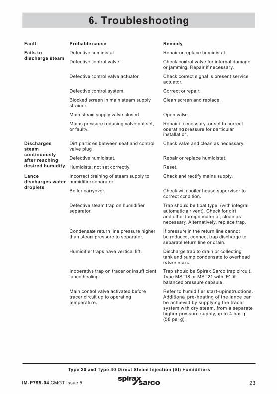
Fault Probable cause Remedy
Fails to discharge steam
Defective humidistat. Repair or replace humidistat.
Defective control valve. Check control valve for internal damage or jamming. Repair if necessary.
Defective control valve actuator. Check correct signal is present service actuator.
Defective control system. Correct or repair.
Blocked screen in main steam supply strainer.
Clean screen and replace.
Main steam supply valve closed. Open valve.
Mains pressure reducing valve not set, or faulty.
Repair if necessary, or set to correct operating pressure for particular installation.
Discharges steam continuously after reaching desired humidity
Dirt particles between seat and control valve plug.
Check valve and clean as necessary.
Defective humidistat. Repair or replace humidistat.
Humidistat not set correctly. Reset.
Lance discharges water droplets
Incorrect draining of steam supply to humidifier separator.
Check and rectify mains supply.
Boiler carryover. Check with boiler house supervisor to correct condition.
Defective steam trap on humidifier separator.
Trap should be float type, (with integral automatic air vent). Check for dirt and other foreign material, clean as necessary. Alternatively, replace trap.
Condensate return line pressure higher than steam pressure to separator.
If pressure in the return line cannot be reduced, connect trap discharge to separate return line or drain.
Humidifier traps have vertical lift. Discharge trap to drain or collecting tank and pump condensate to overhead return main.
Inoperative trap on tracer or insufficient lance heating.
Trap should be Spirax Sarco trap circuit. Type MST18 or MST21 with 'E' fill balanced pressure capsule.
Main control valve activated before tracer circuit up to operating temperature.
Refer to humidifier start-upinstructions. Additional pre-heating of the lance can be achieved by supplying the tracer system with dry steam, from a separate higher pressure supply,up to 4 bar g (58 psi g).
6. Troubleshooting

IM-P795-04 CMGT Issue 524
Type 20 and Type 40 Direct Steam Injection (SI) Humidifiers