Human Rating the Orion Parachute System
44
Human Rating the Orion Parachute System Carol Evans, Tim Fisher, Ricardo Machin and Christine Stewart NASA Johnson Space Center, Houston, TX 77058 Human rating begins with design. Converging on the requirements and identifying the risks as early as possible in the design process is essential. Understanding of the interaction between the recovery system and the spacecraft will in large part dictate the achievable reliability of the final design. Component and complete system full-scale flight testing is critical to assure a realistic evaluation of the performance and reliability of the parachute system. However, because testing is so often difficult and expensive, comprehensive analysis of test results and correlation to accurate modeling completes the human rating process. The National Aeronautics and Space Administration (NASA) Orion program uses parachutes to stabilize and decelerate the Crew Exploration Vehicle (CEV) spacecraft during subsonic flight in order to deliver a safe water landing. This paper describes the approach that CEV Parachute Assembly System (CPAS) will take to human rate the parachute recovery system for the CEV.
Transcript of Human Rating the Orion Parachute System

Human Rating the Orion Parachute System
Carol Evans, Tim Fisher, Ricardo Machin and Christine Stewart NASA Johnson Space Center, Houston, TX 77058
Human rating begins with design. Converging on the requirements and
identifying the risks as early as possible in the design process is essential. Understanding of the interaction between the recovery system and the spacecraft will in large part dictate the achievable reliability of the final design. Component and complete system full-scale flight testing is critical to assure a realistic evaluation of the performance and reliability of the parachute system. However, because testing is so often difficult and expensive, comprehensive analysis of test results and correlation to accurate modeling completes the human rating process. The National Aeronautics and Space Administration (NASA) Orion program uses parachutes to stabilize and decelerate the Crew Exploration Vehicle (CEV) spacecraft during subsonic flight in order to deliver a safe water landing. This paper describes the approach that CEV Parachute Assembly System (CPAS) will take to human rate the parachute recovery system for the CEV.

American Institute of Aeronautics and Astronautics
1
Human Rating the Orion Parachute System
Ricardo A. Machín1, Timothy E. Fisher2, Carol T. Evans3, and Christine E. Stewart4 National Aeronautics and Space Administration, Johnson Space Center, Houston, TX 77058
Human rating begins with design. Converging on the requirements and identifying the risks as early as possible in the design process is essential. Understanding of the interaction between the recovery system and the spacecraft will in large part dictate the achievable reliability of the final design. Component and complete system full-scale flight testing is critical to ensure a realistic evaluation of the performance and reliability of the parachute system. However, because testing is so often difficult and expensive, comprehensive analysis of test results and correlation to accurate modeling completes the human rating process. The National Aeronautics and Space Administration (NASA) Orion program uses parachutes to stabilize and decelerate the Crew Exploration Vehicle (CEV) spacecraft during subsonic flight in order to deliver a safe water landing. This paper describes the approach that the CEV Parachute Assembly System (CPAS) will take to human rate the parachute recovery system.
I. Introduction What does it mean to human rate a parachute system intended as the primary means for landing humans
returning from space? Searching past and present publications in the NASA archive produces multiple documents on the subject of human rating. Human rating is the process of satisfying the mutual constraints of cost, schedule, mission performance, and risk while addressing the requirements for human safety, human performance, and human health management and care.1 Each independent element associated with the spacecraft is not required to obtain Human-Rating certification, the certification is for the entire crewed space system. However, the approach to seek independent certification of elements of the crewed system is sometimes considered to be a more logical approach.2 Almost every trailing deployable aerodynamic decelerator system is unique, it is not possible to generate a single generic document that could outline what this process to human rate would require. In the United States the Federal Aviation Administration has published standards for both sport jumper and powered parachute applications, but neither of these approaches the scale or complexity of a spacecraft parachute recovery system. Personnel parachutes, both civilian and military, are deployed at altitudes achievable by common aircraft and can be tested relatively quickly and inexpensively in order to statistically demonstrate reliability. The complexities of integration within a spacecraft can make ensuring repeatable safe deployment a unique challenge. The mass restrictions on a spacecraft parachute system do not allow the robust margins typical in a military cargo system. The difficulty of getting a spacecraft test article to the altitude and velocity required to initiate the parachute recovery system using standard aircraft delivery techniques alone makes the flight testing aspect extremely expensive. It is not difficult to see how it quickly becomes prohibitive to statistically demonstrate the performance and reliability of a human rated spacecraft parachute recovery system with testing alone. Within the NASA experience3, the Apollo Earth Landing System stands as the best documented project that achieved this accomplishment in terms of the design, testing, and qualification of a parachute system for safely returning humans from space. Bob West’s “Apollo Experience Report – Earth Landing System” is an excellent summary of what Apollo did.4 Because of the similarity between the CPAS and Apollo designs, the CPAS project has chose to use the Apollo approach as the outline for human rating the parachute recovery system for the Orion*5CEV Crew Module.
1 Orion Parachute System Chief Engineer, Applied Aeroscience and CFD Branch, Mail Stop EG3, AIAA Senior Member. 2 Orion Parachute System Lead Systems Engineer, Vehicle Systems Engineering and Integration Branch, Mail Stop EA34, AIAA Senior Member. 3 Orion Parachute System Test Lead, Test and Fabrication Branch, Mail Stop EA36. 4 Orion Parachute System Safety and Mission Assurance Lead, Quality Assurance Branch, Mail Stop NT3. * At the time of this writing, the Orion project is being renamed the Multipurpose Crew Vehicle Program.

American Institute of Aeronautics and Astronautics
2
While the term “human rate the parachute system” is used, it is important to draw the distinction that it is the overall spacecraft system that is receiving the certification. This paper describes the design, testing, and analysis that the CPAS is performing, it is not intended to explain the entire spacecraft human rating process. The phrase “human rate the parachute system” represents, within the context of the overall spacecraft system, the portions of the human rating package that are expected from and provided by the parachute subsystem.
The approach implemented is consistent with JSC-659855, Requirements for Human Spaceflight for the Trailing Deployable Aerodynamic Decelerator System, which documents the minimum set of design and test requirements for the Crew Module parachute recovery system. The human rating process culminates in a certification granted by the NASA Associate Administrator to the Program Manager for the system. However, this process starts even before the System Requirements Review (SRR), and continues through the major milestones at the System Design Review (SDR), Preliminary Design Review (PDR), Critical Design Review (CDR), and Operational Readiness Review (ORR) as defined in NPR 7120.5.6 At each of these reviews, the Program Manager provides evidence of meeting the requirements of NPR 8705.2B7, Human-Rating Requirements for Space Systems. This evidence is reviewed and approved by the NASA Chief Engineer, the NASA Chief of Safety and Mission Assurance, the NASA Chief Health and Medical Officer, and the Johnson Space Center Director. The adequacy of those products and the acceptability of progress toward Human-Rating Certification are used to verify compliance. H.C. Shivers2 provides an excellent summary of the requirements and processes required for human rating identified in NPR 8705.2 along with a concise set of references.
The verification that the CPAS design performs in a reliable and repeatable manner, meeting the requirements, will ultimately be primarily a combination of testing and analysis. As the CPAS project is not complete at the time of writing this paper, much of the later phases work described will reflect what is planned.
II. CPAS Overview The CPAS is a Government Furnished Equipment project responsible to provide the parachutes and associated
analysis/models for safely landing the Orion CEV Crew Module. Similar to the Apollo Earth Landing System design, CPAS is stored in the Crew Module forward bay beneath a forward heat shield that is jettisoned during subsonic flight prior to parachute deployment. Like Apollo, following forward heat shield jettison the CPAS implements a pair of independently mortar deployed subsonic conical ribbon drogues to decelerate and stabilize the crew module. The drogues are released and three independently mortar deployed conical ribbon pilot parachutes are used to deploy the three Ringsail mains. The drogues and mains are attached to a single structural point on the top of the crew module, referred to as the ‘flower pot’ on Apollo and the ‘gusset zero’ on the Orion CEV. In all the aforementioned aspects, the CPAS is nearly identical to the Apollo design only larger.8 The concept of operations is shown for nominal entry and low altitude aborts in Figures 1 and 2, respectively. CPAS has 68 requirements the design must be verified to meet. These requirements span from identifying the environments and interface the design must be compatible with, to the performance the design must provide. At the outset, traceability of the requirements to parent specifications up through to the Crew Module requirements was confirmed. The requirements were also reviewed to confirm that they would be verifiable as written and criteria by which to determine success were agreed to.

American Institute of Aeronautics and Astronautics
3
Figure 1. CPAS Nominal and High Altitude Ascent Abort Deployment Sequence
Figure 2. CPAS Low Altitude Ascent and Pad Abort Deployment Sequence

American Institute of Aeronautics and Astronautics
4
III. Design A simplified overview of the design
flow that has been implemented in the CPAS project is shown in Figure 3. The cycles of this process are tied to the project phases where the design, testing (as applicable), and analysis culminate in the milestone reviews as specified in NPR 8705.2. The iterative nature of this process lends itself to implementing changes in the requirements, which often occurs in the early phases of the spacecraft design. The models and test data are continuously used to assess the performance of the design and it’s adequacy as the project progresses through its phases. This also allows for the results of testing and/or model changes to drive modifications into the parachute system design. The progression of design changes due to observed failure modes contributes to demonstrated reliability growth.
Verification is the formal process of using any combination of the methods of test, analysis, inspection, or demonstration, to confirm that a system satisfies all specified performance and operational requirements. In the flow chart the leap to verification is not performed until after the qualification testing has been completed. This final verification will involve not only the performance models and airdrop test results but include demonstrations where modeling is not considered viable, such as main bag retention and deployment. Verification will in some cases include inspections and process controls associated with the quality of the delivered hardware (including manufacture, packing, and rigging of the parachutes). This is specifically true of textiles, where proof loading of the actual flight hardware is not considered advisable due to the destructive nature of the testing and because the CPAS is considered a onetime use deliverable.
Usually the focus on improving and assuring reliability starts after an architecture and preliminary design have been selected. This is too late and misses perhaps the greatest leverage of all in ensuring the most reliable system is fielded, the influence of architecture and preliminary design often have a greater effect than any of the other techniques available later in the project life cycle. Performing an initial hazard analysis and Failure Modes and Effects Analysis (FMEA) provided insight into what potential hazards are affected by the designs, and are invaluable when performing risk trades on different design options. Probabilistic Risk Assessments (PRAs) were also valuable in performing risk trades on alternative design options, by comparing potential reliabilities of various options. The allocation of risk and mass between the various systems on the spacecraft often results in requirements that are difficult to achieve without compromising the reliability of the design. Several distinct examples of negotiating requirements changes to improve system reliability have occurred during the CPAS project.
The original requirement for land landing, combined with the volume allocated to the parachute recovery system and the geometry of the Crew Module, resulted in the Generation 1 design having a confluence fitting suspended above the Crew Module for the main parachute phase of descent (much like the Apollo Block-I design). When the requirement to land with the heat shield perpendicular to the landing surface was removed, and because the water landing (like Apollo) would require a hang angle in order that the heat shield pierce the surface first, the Landing and Recovery System (of which CPAS is a part) was able to negotiate a single point attach to the crew module for the main parachutes. This change removed a metallic single point failure from the design and significantly simplified the storing and deployment of the main parachute system. A second example, that will discussed in the Gen-1 section of testing, of a simplification to the CPAS requirements and design was the removal of the torque reducer.
The third example of a spacecraft level requirement that was eventually changed and improved the reliability of the CPAS design was the evolution of the drogue deployment envelope. As will be discussed in the Engineering Development Unit (EDU) testing section, the ability to conduct airdrop testing at high altitudes is very limited. However, there are several risks associated with high altitude subsonic Mach number parachute deployments that
Models & Simulations
Verification
Test Design
Requirements
Test Refines Models
Models/Sims used to verify
Assess Design
Build/Realize the Design
Test Results Used to Verify
Model Informs Design
Figure 3. Simplified Parachute System Design Overview.

American Institute of Aeronautics and Astronautics
5
are not well understood by the parachute performance modeling community. As a result very few designs have documented this ability, accordingly there is limited to no data available for anchoring of simulations. In the case of the drogue deploy envelope, as the Crew Module aerodynamic database became better understood the Guidance Navigation and Control group was able to analytically demonstrate that deploying the drogues at lower altitudes was achievable. This significantly decreased the range of altitude and Mach number over which the CPAS would have to extrapolate performance models relative to where those models could be anchored by test data.
However, as with any parachute recovery system design, the CPAS is sensitive to parameters that are not within control of the designers, specifically the aerodynamic and the mass properties of the Crew Module. For the CPAS Preliminary Design Review the Orion program chose to flow down what were considered to be a conservative set of assumptions for both of these aspects of the Crew Module design, referred to as Robust Initial Conditions. The intent of the Robust IC’s was to allow the design and testing of the CPAS to continue and not require additional loops within the Model-Design-Test loop. It was recognized that by working to Robust IC’s the system would have additional margin over what would eventually be the ‘true requirements’. While this would result in a CPAS design that was not optimized for weight, it was considered acceptable due to the long design, test, and verify cycle time associated with parachute systems.
The CPAS chose to use both the parachute contractor simulation (Airborne Systems’ DCLDYN) and the NASA simulation Decelerator Systems Simulation (DSS) to predict the parachute inflation and steady state performance of the design. Each simulation implements code for predicting loads consistent with the Force-Trajectory-Time method described in section 5.4 of NWC-TP-6575.9 Both simulations predict a ‘total parachute’ load (i.e. not distinguishing between the individual parachute loads). The simulations differ in how the parachutes are coupled to the payload and the degrees of freedom that each body (the parachutes and the payload) is represented with. While the use of two simulations is not critical to the human rating of the system, it does provide an opportunity to uncover discrepancies between the models, and possibly identify aspects of the predictions where errors could exist. Both of the models were modified through this process of redundant reconstruction of drop test data and comparison. However, for the final verification, it is the Government DSS model that will be used to ensure compliance with requirements.
Based on applicable historical cluster load share data (primarily Apollo), CPAS chose to assume that in a cluster of three mains the maximum load any single parachute could experience could be no greater than 50% of the peak total predicted cluster parachute load. In a cluster of two (drogues or mains in this case) the maximum load a single parachute could experience was assumed to be no greater than 65% of the peak total predicted cluster load. These assumptions were important for calculating the structural margins of the individual parachutes and how they attach to the Crew Module.
The parameters in the parachute performance models were initially based on past performance of the chosen canopy design (provided by the parachute contractor, Airborne Systems). However as testing progressed this model and the associated parameters were modified to reflect the performance observed for the CPAS implementation, specifically canopy loading and deployment conditions. Each parameter in the model has a mean value and an uncertainty applied. The model for terminal rate of descent at touchdown reflects the statistical nature of cluster performance, based on the distribution of data measured during testing.10 Lacking a suitable reference or sufficient data, the uncertainties have been applied as a uniform distribution in the Monte Carlo simulations used to generate load predictions. CPAS is attempting to generate and analyze air drop test data to determine if there is a more appropriate or tailored distribution for the uncertainties to these parameters.
The CPAS is fault tolerant in that the loss of a single drogue and/or main will not result in loss of crew. However, failure of the gusset zero attach on the Crew Module would be catastrophic. Designing the gusset zero attach for all of the Monte Carlo predicted parachute load cases would be prohibitively heavy for the spacecraft. The requirements for CPAS, shown in Table 1, have identified the percentage of the Monte Carlo cases that must not exceed the maximum allowable individual canopy or total cluster load. The percentage varies depending on the number of failures experienced and are linked to the overall system requirement for reliability. This approach reflects a balance of risk of failure and system mass.

American Institute of Aeronautics and Astronautics
6
The design of the CPAS hardware involves the implementation of safety and derating factors associated with the use of textile components. Consistent with the methodology described in section 6.4.3 Load and Design Factors found in NWC-TP-65758, a safety factor of 1.6 has been applied to all non-safety critical components of the textile design. Critical components of the textile design, such as the reefing system, have a safety factor of 2.0 applied. The identification of the reefing system as safety critical has more to do with protecting the Crew Module (i.e. not tearing the gusset zero attach fitting off the Crew Module) than preventing a skipped stage from failing a canopy. The derating and load amplification factors for the textiles, shown in Table 2, were applied to each individual load carrying element (raw material and/or seam and joint). The derating factors are associated with joint efficiency, abrasion, fatigue, contamination, temperature, and aging. Load amplification factors, such as dynamic, asymmetric, and convergence were also applied to the Safety Factor to determine the total Design Factor for any given element of the design. These values were taken from the vendor/supplier of the material, from applicable and published experience reports, or from the parachute contractor experience. In all cases, the values were reviewed and approved for use by the JSC Engineering Directorate and the Safety Review Board for application in the CPAS design.
All material lots were tested for critical performance parameters (such as tensile and tear strength, permeability, density, etc.) prior to implementation on canopy builds. All materials were stored in environmentally conditioned and controlled access areas. On the CPAS project, five individual seam and joint samples manufactured on two different machines (with unique operators) were tested for joint efficiency (a total of ten samples). These tests were conducted at lab temperatures, under static loading conditions; no attempt was made to capture the high strain rate effect on the joint efficiency. The joint efficiency was calculated relative to the actual tested mean strength for the raw material (determined during material lot acceptance testing). As a rule, the goal for every seem and joint was to achieve no less than 80% efficiency. Where this was not met and the actual efficiency causes the designer to move to a new (heavier) class of material strength, the design of the
seam or joint was reviewed and alternate solutions were tested in an attempt to get back to the lighter class material. Currently, there are no custom textile materials implemented in the design and manufacture of the CPAS.
One of the more interesting findings during the Gen-2 testing (related to materials and canopy design) was that the broadcloth, which was within specification prior to manufacturing, was found to be out of specification with respect to permeability post manufacture (prior to its first airdrop test). As the CPAS is a onetime use type of hardware, and since the system performance as measured during testing to date was satisfactory (with this change in permeability present), the team is working on a way to use the EDU and Qualification testing experience (both in terms of materials and system performance) to establish a criteria by which this increase in permeability will be recognized as normal and acceptable. This experience represents growth in the reliability of the system performance through better understanding of how the actual manufacture processes affects the performance models.
Table 2. Textile Derating and Load Amplification Factors.
Table 1. Monte Carlo Load Coverage Requirements

American Institute of Aeronautics and Astronautics
7
CPAS has chosen to implement steel cable risers for the lower portion of the load path where the parachutes interface to the Crew Module to protect against the possibility of the risers coming in contact with the Crew Module. All metallic components within the parachute system were designed with a Factor of Safety of 1.0 to yield and 1.6 to ultimate. A Fitting Factor of 1.15 was applied to the link assembly (where the suspension lines interface to the steel cable riser). Prior to assembly of the flight hardware, the individual steel cable risers will be proof loaded to 60% of the minimum breaking force (approximately 1.3 times the design limit load of the riser). This proof loading will be performed to demonstrate workmanship of the swaged end fittings and is part of the acceptance of the hardware from the vendor. The practice of proof loading the textile components is not considered advisable due to the high likelihood of damaging the material. Confidence that the textile load path is adequate is achieved through material acceptance testing prior to, and controls implemented during, the manufacturing to assure that the flight build is consistent with the development and qualification hardware.
IV. Manufacture During the manufacturing process, quality control points are inserted to assure the materials and construction of
the canopies are consistent and per specification. The parachute contractor Mandatory Inspection Points (MIPs) have been reviewed and agreed to by the CPAS team. These include, but are not limited to, 100% inspection of all stitching, and X-ray of packed parachutes with cutters to assure they have not been bent during the packing process. Government Mandatory Inspection Points (GMIPs) which are verified by the DCMA (an independent government assigned inspector) have been added at critical points in the process. These critical points are identified by reviewing the hazard analysis and FMEAs for the vulnerable areas of the design. Any specific part of the design where failure could lead to loss of the system, and consequently the crew, should be inspected as late as reasonably possible in the manufacturing process. These GMIPs include material lot acceptance test results, aspects of the marking and cutting of the raw materials, and assembly. Acceptance inspections are conducted on each completed assembly to verify the critical elements have been manufactured per specification in the drawings. An example of an acceptance inspection point would be verification that the vent hoop has the proper number of turns of material. The CPAS is implementing these MIPs and GMIPs during manufacturing of the EDU to gain experience prior to fabrication of the qualification and flight hardware builds. Consideration was given to minimize impact on the manufacturing process in the generation of the GMIPs without compromising the intent of these independent inspection points.
This same approach for quality control will be implemented for the rigging and installation of the hardware, as yet unidentified for the flight hardware.
V. Testing It is difficult to overemphasize the importance of testing. Testing can reveal failure modes in the system that
would be found by no other technique. In particular full scale testing at flight conditions (of flight like hardware from flight like interfaces) is often the only way to learn how the parachute system interacts with the spacecraft during deployment, a notoriously difficult phase of operation to model accurately. Testing not only provides objective evidence that the design meets the requirements, it also serves to anchor the models used to predict performance. The CPAS will have four phases of testing when complete; Generation 1 (Gen-1), Generation 2 (Gen-2), Engineering Development Unit (EDU), and Qualification. Within each phase a series of ground and airdrop tests were conducted (or planned in the case of EDU and Qualification). The generic goals of the testing are to understand the design, improve the modeling, and reduce risk.
A. Generation 1 Gen-1 represents the original CPAS design. This first phase of testing was proof of concept, recognizing the
Crew Module was still being designed and the requirements were very likely to change. Because large parachute systems typically require a long lead time for design and development, this investment was considered critical to being able to deliver the flight design in a timely manner after the vehicle design and requirements settled down.
As previously discussed, the standard set of lab tests (materials, seam and joint) were conducted in support of the canopy design. No ground extraction tests of stowed mains were performed for Gen-1. Several ground mortar shots were performed to demonstrate the gas generator charge was sufficient to achieve the 125 ft/sec exit velocity desired and that the deployment bag produced an orderly deployment of the drogue and pilot in static air.
The Gen-1 system was airdrop tested in a variety of configurations, ranging from single canopies to clusters.11, 12 The parachutes were predominantly tested from simple static line type sequential deployment test articles, using non-flight like retention and deployment bags. The main canopies were deployed once from an accurate retention

American Institute of Aeronautics and Astronautics
8
system and forward bay mounted to a weight tub on Cluster Development Test 1 (CDT-1). The forward bay for CDT-1 represented an accurate interface allowing for the main retention system to be implemented and the rigging procedures to be refined. The pilots were mortar deployed on CDT-1, however the drogues were static line deployed following Low Velocity Air Drop (LVAD) extraction of the test article from the aircraft. Only two tests were attempted of the Gen-1 design from a flight like boiler plate vehicle, where all the mortars would be used to deploy their associated parachutes. The boiler plate added the proper forebody shape to the test (heat shield diameter and lip) providing an accurate wake behind the vehicle for the deployment conditions tested. One of these tests (Cluster Development Test 2) did not achieve the intended test point due to a programmer failure13, the other (Pad Abort 1) worked flawlessly to recover the boiler plate following the first test of the launch abort system at the US Army White Sands Missile Range.
The airdrop test data collected during the Gen-1 tests, from canopy inflation to steady state performance, were used to update the parachute models. The updated models were then used to perform Monte Carlo simulations varying both the parachute system performance as well as those parameters outside the control of CPAS, things like atmospheric properties, Crew Module performance, and mass properties. The conditions at which the CPAS would be implemented, ranging from nominal entry to ascent and pad aborts, were also varied as families of simulation runs. These results have been used to assist in the design of the Crew Module as well as direct changes to the CPAS design. As the Crew Module concept of operations has evolved, specifically changes to the crew module aerodynamic database, going to water landing only, and changes in the recovered weight, the Gen-1 design has became obsolete.
One outcome at the end of the Gen-1 testing (combined with the evolution of the Crew Module) was that the design and analysis teams generated a list of concerns and risks that were as yet not well understood. These risks and concerns covered a broad range of the design and performance, from identification of where the contractor and/or industry had little experience in analytical predictions, to the complexity of the riser routing and main retention system. This list was then sorted into low, medium and high risk with respect to severity of consequence and likelihood of occurrence. Some of the tests identified were considered standard good practice, such as structural grid overload testing. These achieved a high ranking as they are the basic building blocks of having confidence in the design (beyond simply applying the analytical techniques to demonstrate positive margin of safety). Others such as the performance of the drogues in a clean wake, were recognized as worth testing but considered low in terms of risk, primarily because the drogue planform has not changed for the subsequent design cycles (it has simply increased in design limit load).
B. Generation 2 It was during the Gen-1 airdrop testing that variations in the full open steady state main rate of descent
performance were observed.14 Based on analysis of the airdrop test data, two primary components were identified that contributed to the variations; canopy breathing and canopy oscillation angle.15
The canopies tended to have a ‘breathing’ motion, where the shape of the canopy would vary over time. Photogrammetric techniques were applied to the payload upward looking cameras to determine the projected diameter of the skirt as a function of time. The geometry of the payload oscillating in the vertical axis due to this change in the geometry of the structural grid was identified as one component of the variation in rate of descent.
In addition to the breathing the canopies tended to have a large oscillation angle, referred to as ‘fly out’. This manifested itself as gliding in the single main tests and as a cyclic motion of flying apart and crashing (or ‘clapping’) in the cluster tests. Photogrammetric techniques were also applied to the upward looking camera data to track the vent of each canopy and determine the time history of the main canopy fly out angles. On the cluster tests this correlated directly to the sinusoidal variation in the rate of descent for the payload.
Statistical analysis of the rate of descent data, with the aforementioned variations present, indicated the terminal system performance exceeded the requirements. This suggested that there was performance that could be traded to achieve greater stability in the main full open cluster. If the stability of the cluster could be improved at the expense of drag performance the torque transmitted to the Crew Module could be reduced (the torque limiter is discussed in greater detail in the EDU testing section). This understanding of the performance led directly to the main canopy modifications tested during the Gen-2 testing.
The planform design for the three canopy types within the CPAS, drogues, pilots, and mains, were not changed at the commencement of the Gen-2 testing. The first change introduced to all of the Gen-2 testing was an increase in the suspended weight (or canopy loading), consistent with the evolution and weight increase of the Crew Module (going from approximately 17,000 lbs to 20,000 lbs landed).
In addition, several changes to the main canopy design were tested in the Gen-2 test series in an attempt to improve the stability of the full open mains. An Over Inflation Control Line (OICL) was implemented to assess the

American Institute of Aeronautics and Astronautics
9
improvement in canopy oscillation and breathing. The geometric porosity of the main was modified, implementing a combination of both the Apollo and F-111 geometric porosity modifications. An increase in line length ratio (from 1.15 to 1.4) was also tested. Based on the airdrop test data collected, the combination of increased porosity and line length were determined to still provide adequate terminal rate of descent performance while improving the stability of the main cluster. Without these canopy design changes the CPAS would have been forced to add a torque limiter (effectively a hoop around the risers several feet above the Crew Module) to limit the torque. It was recognized that implementing such a torque limiter would introduce new hazards to the design and packaging of the mains, decreasing the overall reliability of the system. The EDU tests will provide additional experience and data to validate the steady state terminal performance under mains.
It was considered highly unlikely that a reefed canopy would skip a stage, but not a zero chance. The predicted loads for a single main skipping first stage in a cluster (with one drogue already failed) generates the design load case for the gusset zero attach, a potentially catastrophic failure. Additionally, a skipped first stage drogue is also the defining case for the drogue attach points to gusset zero. This specific test objective, a skipped stage drogue or main, was initially performed during the Gen-2 test series. These tests implemented a single canopy configuration, and the data was used to corroborate the model for a skipped stage performance. Skipped stage will be attempted again for the mains during the EDU testing, only this time with a cluster of mains in order to discern the interference and blanketing affect associated with a cluster of large canopies (recognizing it is difficult to guarantee which of the independently deployed mains will start to inflate first in a cluster).
C. Engineering Development Unit The EDU testing, also referred to as the Generation 3 by the simulation and analysis team, is comprised of a
combination of ground and airdrop testing. A number of ground tests were identified during the risk review for the EDU design, following the Gen-1 and Gen-2 testing. These tests include: torque model validation testing, steel cable abrasion testing, main deployment bag ground extraction tests, vibration testing of the main retention system, pneumatic mortar deployment tests of the drogue parachute with a steel cable riser, full up gas generator mortar deployed drogue deployments, and raw fiber degradation due to exposure to Reaction Control System (RCS) propellant and by products.
The EDU ground testing began, where necessary, with the materials seam and joint testing. In addition to seam and joint testing where the design has changed, a series of tests to characterize the degradation of the raw fiber for the textiles used will be conducted exposing them to the raw propellant and exhaust by-products from the RCS motors used to orient the Crew Module. These degradation factors will be implemented into the stress analysis of the canopy structure to confirm that all components of the design still have positive margin of safety.
The Orion CEV must orient the Crew Module and crew within a narrow band of the ground track heading angle in order to safely land. The torque model calculates the torque the main canopy risers transmit to the Crew Module via the gusset zero attach point. This model is implemented by the Crew Module landing simulations to demonstrate the RCS can perform this re-orientation just prior to landing. A model for amplitude and period of the main canopy fly out angles, which are parameters within the torque model, were determined from the photogrammetric analysis of the Gen-1 and Gen-2 test data.14 When the updated model for cluster stability was implemented into the torque model, and subsequently into the integrated Crew Module landing simulations, the fly out behavior of the mains was determined to cause the heading angle to be outside of the requirements at landing. One major design change implemented at the Preliminary Design Review (prior to the EDU design and testing) was the addition of steel cable to the lower portion of the riser. These were added to protect for the possibility of the risers coming in contact with hot surfaces on the Crew Module. However, this bundle of steel cables also directly affects the torque the parachutes can impart to the Crew Module. The changes tested during the Gen-2 testing, specifically the increased geometric porosity and increased line length ratio, have improved the main canopy stability and demonstrated a reduction in the predicted torque imparted to the Crew Module. The model of amplitude and period will be matured as the EDU and Qualification airdrop tests are conducted.
The ground extraction tests involve demonstrating the extraction of the main deployment bags and risers at various pilot pull angles that the simulations suggested would be experienced in flight. The ground extraction tests are considered critical because there is not sufficient confidence in analytical techniques to predict the dynamics of the main deployment bag during extraction and whether the possibility of adverse re-contact with the Crew Module can take place during deployment.
Tests are planned to characterize the degradation the steel cable risers will experience as a result of riding up on the Crew Module structure while under load. These tests will be conducted on several different ‘target’ surfaces and bend radii, both as a static bend angle and with the abrasion surface moving. The ‘target’ obstacles were identified using the results of the multi-body multi-degree of freedom simulations for the hand off from drogues to mains.

American Institute of Aeronautics and Astronautics
10
These tests will include the case where one riser cable is ‘pinned’ by the other cables and ‘crushed’. These tests will provide the necessary data to verify that the steel cable risers will have positive margin of safety even after coming in contact with the vehicle.
The main deployment bags are restrained in the forward bay with a lacing system similar to that employed by Apollo. This design will be tested on a vibration test facility subjecting the single bay with a main secured to the ascent vibration environment, including that for a launch abort. The deployment bag will be instrumented with accelerometers inside the bag in an attempt to correlate the external excitation to what the packed bag experiences in places like the reefing cutter pockets.
The drogue deployment will be tested using two different ground based test beds. The first will be a pneumatic mortar, using tanks of compressed gas to accelerate the packed drogue to various velocities. The primary test objective is to verify the initial deployment and rotation of the pack, specifically to understand the effect of the steel cable riser and associated transition to textile riser on the mortar ejection performance all the way through to canopy exposure. These tests will be followed by a series of pyrotechnic gas generator mortar deployments as the final verification of the flight design combined system deployment performance prior to proceeding with airdrop testing.
The EDU phase of airdrop testing has a total of sixteen planned air drop tests. There are multiple primary objectives to the EDU airdrop test campaign. The first is to explore and eliminate the risks identified in the design during the Gen-1 and Gen-2 tests. The second is to explore the envelope of deployment conditions that the requirements have levied, specifically the high altitude drogue deploy in the wake of the vehicle and to bound the entire main deployment envelope. The ability to accurately model a main bag being deployed from the stowed configuration is not currently possible, however it is recognized that this is probably the single most likely risk that could result in a failure of the system. The early off-angle ground extraction tests are part of mitigating and understanding this risk, but actual demands in airdrop testing is where this third primary objective is addressed, in an attempt to drive out latent failure modes so that they can be addressed prior to qualification testing. As a result of this risk, every EDU airdrop test will implement flight design retention system and deployment techniques (i.e. mortar deployments) from a flight vehicle accurate forward bay.
Two test article types are being developed for the EDU testing. The first is a cylindrical test article that can be mounted onto a Type-V pallet and extracted from an aircraft using the LVAD technique. This Parachute Compartment Drop Test Vehicle (PC-DTV) is then separated from the pallet and stabilized with a programmer parachute. After a short period of time, test condition specific, the programmer is released and the test of the CPAS hardware commences. The PC-DTV can be ballasted to the Crew Module weight and has a full scale flight vehicle accurate forward bay on the back of the missile, allowing CPAS to restrain and deploy the hardware in a flight like configuration (including mortars). A computer aided design sketch of the PC-DTV is shown on the left of Figure 4. The PC-DTV extracted from a C-130 aircraft is the least expensive, least complicated, and most available of the airdrop test techniques available to CPAS.
The PC-DTV, while affording the opportunity to demonstrate the entire parachute recovery sequence at flight
like dynamic pressures, does not generate a wake that is similar to that of the Crew Module. The second airdrop test article that CPAS is building is called the Parachute Test Vehicle (PTV), essentially a boilerplate that accurately models the heat shield of the Crew Module (shown on the right side of Figure 4). The two test articles share an identical ‘flight like’ design for the forward bay compartment, where the CPAS is stowed and deployed from. The PTV is too wide to be airdrop tested from a C-130 aircraft. Due to height restrictions associated with performing an LVAD type extraction out of a C-17 aircraft the forward bay of the PTV is lowered by 18 inches with respect to the heat shield, causing the back-shell angle of the PTV to not match that of the Crew Module. For the range of angles of attack that the CPAS is required to perform in, this difference is not considered to be important. While providing
PC-DTV PTV Figure 4. The EDU Test Vehicles

American Institute of Aeronautics and Astronautics
11
the proper wake, the PTV has the disadvantage of not being able to reach the high dynamic pressures levied in the requirements. This is in part due to the requirements reflecting Robust ICs and in part due to PTV requiring the use of a programmer parachute (since it does not have an RCS).
Both test articles, PC-DTV and PTV, can also be delivered to test point using a balloon. The concept of operations for these tests will be to lift either test article coupled to a balloon to medium altitudes, roughly 40,000 ft MSL, and then release it, static line deploying the programmer parachute. The test sequence would proceed similar to an LVAD test with the sequence of events controlled by a redundant electronic sequencer onboard the test article.
Figure 5 plots the predicted performance of the two test articles along with the CPAS deployment envelope
requirements as a function of Mach number and altitude. The constant dynamic pressure isobars have been co-plotted over the Mach-altitude plot. Both delivery techniques are overlaid, the LVAD technique using either a C-130 or a C-17 aircraft, and the balloon.
The Orion Crew Module, like the Apollo, is unstable sub-sonically. The Guidance Navigation and Control simulations currently show that the Crew Module can, under nominal conditions, maintain controlled flight all the way down to the ellipse labeled ‘Nominal Entry’ for drogue deploy. However, the Crew Module has a requirement to be able to return with one of the two strings of RCS jets failed. Combined with the uncertainties in the Crew Module aerodynamic database, the earth’s atmosphere, and the entry vehicle mass properties, this Crew Module level requirement results in the CPAS drogue deploy box as the solid red line. The main deployment box is the much smaller box (lower left), ranging in Mach from roughly 0.15 to 0.3 and in altitude from roughly 4,500 ft to 8,000 ft MSL. Nominal main deploy (returning from space) will be at 8,000 ft MSL. The concept of operations for aborts, and specifically when the Crew Module will choose to bypass the drogues and go directly to mains, is not completely defined yet, however it is being designed such that nominal entry and pad abort bound the ‘direct to mains’ predicted main deployment loads. The test article delivery performance plotted is currently the predicted capability. Experience with the separation techniques and the programmer stability could result in the shaded areas changing.
Starting with the easier one first, the aircraft delivery technique will achieve nearly all the required trajectory points for the main deploy box. What little of this box that is not covered will not represent a challenge for the performance simulations to bridge. The same cannot be said of the drogue deploy box. Based on the current predictions, it will not be possible to simultaneously match the Mach number, dynamic pressure, and vehicle wake with the test techniques available to CPAS. Permutations of those three environments will be matched separately in
Figure 5. CPAS Required Deployment and Test Technique Envelopes

American Institute of Aeronautics and Astronautics
12
airdrop tests. The simulations, anchored to the points where we can test, will be extrapolated to the full extent of the drogue deploy envelope.
Because of this need to extrapolate the models to outside airdrop tested environments, the CPAS is working with the CEV Aeroscience Project, the Jet Propulsion Laboratory, and the NASA Engineering Safety Council to conduct ground based wind tunnel tests in order to better anchor the tools that are used to predict the wake of the Crew Module and how this affects the CPAS performance.
It is a fact, demonstrated during Apollo, the CPAS Gen-1 and Gen-2 test series, and other previous parachute development programs, that no matter what the intended test matrix is there will be unplanned for events during the testing, and lessons or findings. These will undoubtedly result in either new risks or interactions of the combined CPAS/Crew Module performance to be identified, and/or the need for tests to be repeated. For this reason, two of the sixteen planned EDU tests are carried as ‘anomaly resolution’ in hopes of having the opportunity to react to the today unknown.
D. Qualification Qualification testing is envisioned to be similar to Apollo. Ground tests of materials and difficult to analyze
elements of the design, like the main retention system, will be conducted. A total of eight system airdrop tests are currently identified which will demonstrate repeated nominal deployments as well as the possible permutations of failures (i.e. one drogue handing off to two mains) for which the CPAS is expected to perform. The test articles used for these system tests will be identical to the flight design in terms of how the CPAS interfaces to the Crew Module as well as have the proper forebody shape in order to generate the same wake that the CPAS will experience during flight. In addition to these system level airdrop tests, each individual canopy design will be airdrop tested to no less than 15% over its respective design limit load to demonstrate the structural grid and the drag surfaces have positive margin.
However the basic tenant persists that the only way to achieve a high level of confidence in the deployment and performance of large multiple element parachute system is to test full scale and to test often. While qualification by testing alone will be fiscally prohibitive, the combination of reliability growth demonstrated during EDU testing and the qualification system level tests will provide confidence that the aspects of the performance that cannot be simulated have been thoroughly tested. analysis must play a large role in the qualification process. The confidence that eight system deployments is enough to demonstrate a complicated design such as CPAS will come in part from the experience gathered during the EDU testing, both ground and airdrop, where essentially the same design was demonstrated repeatedly. Special attention will be given to aspects of the design that were changed during the EDU testing as there will be fewer demands from which to draw confidence based on testing.
This confidence is in part reflected in the changes that have been implemented during the Gen-1 and Gen-2 testing. This reliability growth will demonstrate how the development testing has resulted in the identification of aspects of the design that were not robust or poorly understood, allowing the designers the opportunity to demonstrate solutions prior to commencing with qualification testing. A good example of this idea of reliability growth is how the reefing rings were retained to the radials. The test TSE-CDT-2-2 sustained a reefing system failure where the lead main canopy skipped second stage and went directly to full open. The post test analysis indicated that the asymmetry factor assumed was too low resulting in an overload of the reefing system. Subsequent to this test the reefing retention system was modified to show positive margin for the higher loads that were experienced. This change is present in the EDU design for both the drogues and mains.
VI. Verification and Validation The CPAS primary Verification goals are to: 1) Demonstrate that each component and subassembly system is capable of withstanding the mission
environment and function properly with adequate margins, within specified tolerances. 2) Demonstrate the total system will function properly in all specified flight modes and that it meets the
interfaces defined between the various components of the Crew Module and the CPAS. Four basic methods will be invoked to satisfy verification requirements: analysis, inspection, demonstration, and
by test. The qualification ground and airdrop tests will demonstrate the CPAS meets requirements that cannot be modeled with confidence, events like bag retention for the ascent environment and deployment of the hardware. The qualification airdrop testing will collect the data that will allow analysts to verify the inflation and steady state performance models. However the actual validation of the system performance will in most cases be performed by analysis using the results from Monte Carlo simulations.16

American Institute of Aeronautics and Astronautics
13
Figure 6 shows the flow of activities that will result in the analysis and products to verify that the CPAS flight design meets the technical requirements specified.
Not to diminish the importance of any one requirement, two of the most critical requirements will be discussed
in more detail. The rate of descent requirement is written for a standard atmosphere with no wind. However, no airdrop test (certainly not a full scale airdrop test of CPAS) is conducted in a no wind atmosphere. Therefore, while the qualification airdrop test data will be analyzed to confirm that the rate of descent requirement is met throughout the main full open phase of the test, the verification will be performed using models of the full open performance. The statistics used to vary the full open performance will be anchored to applicable EDU and all Qualification airdrop test data. This model will include the transient associated with going from a highly reefed second stage, in the 10 to 15% range, to full open and the associated oscillations in performance.
It is very difficult in a system with multiple independently deployed canopies to be certain the one missing the reefing stage will actually be the first to inflate (the intent of a skipped stage airdrop test). As a result, to attempt to demonstrate by test that the skipped stage load limit will not be exceeded as a primary test objective will almost certainly require many attempts to collect the data and be prohibitive. The CPAS approach for verifying the main cluster will not exceed the allowable load limit at the gusset zero attach will be similar to that used for the rate of descent, by analysis using models that are anchored to airdrop test data.
In all cases, confidence in the mean value and associated uncertainty for the various parameters that predict the parachute performance will be critical. This confidence in the model will come from the cumulative experience of the EDU and Qualification airdrop testing.
VII. Conclusion The CPAS is an extremely lightweight, delicate collection of pieces that absolutely must act together
simultaneously or it will fail with disastrous results. It, alone among the robust pieces of equipment on the Crew Module, must assemble itself in midair at a variety of possible velocities and orientations. When thought of in this fashion it is easy to see why the single most important goal of design should be simplicity. The best approach for
Figure 6. CPAS Verification Flow

American Institute of Aeronautics and Astronautics
14
CPAS has been to make architecture and design choices that avoid complexity and when possible eliminate failure modes. The design reflects the requirements for redundancy and decoupling failure modes to prevent a common cause from compromising the system performance. Care has been taken to introduce robustness with respect to the parameters that could vary outside the control of the parachute recovery system.
It is an interesting problem that large human rated parachute recovery systems face in terms of predicting reliability. Contrary to the prior stated desire to test full scale and to test often, it is recognized that almost any program (CPAS included) cannot afford to test often enough to achieve a high score through traditional test based reliability analysis techniques. The ‘test like you fly’ mantra has been invoked as often as possible, with test techniques developed to achieve as much as possible of the desired operating envelope. The tests have been instrumented such that the models can be anchored to data in the proper flight regimes. A risk based test matrix has been developed in order to give the system every chance to fail prior to qualification. Care has been taken to inspect the hardware and data post test to identify any unexpected performance of the system, both making sure the analytical models reflect the system performance as well as identifying ‘near misses’ that may indicate a possible likely failure mode without actually failing. Changes to the design have been implemented as a result of just such findings of ‘near misses’. These “unknown unknowns” can only be revealed through testing, and only then by diligently reviewing the test results.
NASA has defined a process for human rating, but this process involves human judgment. This can be frustrating for the system designer who would wish to know what design features must be included, what tests must be conducted, and what level of margins must be demonstrated. Every design has different risks, there will always be judgment involved in balancing the process of “satisfying the mutual constraints of cost, schedule, performance, risk and benefit while addressing the requirement for human safety, human performance, and human health management”. Because there are human lives at stake, there must also be some minimum level of safety below which the pressures of cost and schedule become unpersuasive and human rating becomes unachievable.
The CPAS project has successfully completed the Preliminary Design Review phase of the program, and is working through the EDU design and testing in order to reach the Critical Design Review milestone. All requirements appear to be achievable with the EDU design.
Acknowledgments The authors would like to acknowledge the team that has tirelessly worked since 2006 to take the concept of
implementing parachutes for recovering the Orion CEV to a functioning set of hardware. From the team at Airborne Systems where the actual hardware design, manufacture, packing and rigging takes place, to the team at Jacobs Engineering where the test, analysis, and systems integration to the Crew Module takes place, to the team at Lockheed Martin where the negotiations on what the CPAS must accomplish and how it touches the Crew Module take place, to the team of independent experts that have guided the whole process. The names are too numerous to list, but this highly motivated multidisciplinary collection of folks are (forty years after Apollo) demonstrating that parachutes can and will once again be used by NASA to safely return humans from space!

American Institute of Aeronautics and Astronautics
15
References 1 G. Zupp, et. al., “A perspective on the Human‐Rating process of US Crew Module: both Past and Present,” NASA‐SP‐6104, February 1995. 2 C. H. Shivers, “NASA Space Safety Standards and Procedures for Human Rating Requirements,” M09‐0702, 2009. 3 Lowry, C., “Man‐Rating the Apollo and Other Earth landing Systems,” 21st AIAA Aerodynamic Decelerator Systems Conference, May 2011. 4 B. West, “Apollo Experience Report – Earth Landing System,” NASA‐TN‐D‐7437, November 1973. 5 JSC‐65985, Requirements for Human Spaceflight for the Trailing Deployable Aerodynamic Decelerator (TDAD) System, Revision A, November 2010. 6 NPR‐7120.5D, NASA Space Flight Program and Project management Requirements, March 2007. 7 NPR‐87502.5B, Human‐Rating Requirements for Space Systems, 7 Dec 2009. 8 Taylor, T., Machin, R., Royall, P., “Developing the Parachute System for NASA’s Orion – An Overview at Inception,” AIAA 2007‐2577, May 2007. 9 Knacke, T.W., “Parachute Recovery Systems Design Manual,” U.S. Navy Report NWC TP‐6575, Para Publishing Co., Santa Barbara, CA, 1992. 10 Ray, Eric S., “Measurements of CPAS Main Parachute Rate of Descent,” 21st AIAA Aerodynamic Decelerator Systems Conference, May 2011. 11 Bledsoe, K., Englert, M., Morris, A., Olmstead, R., “Overview of the Crew Exploration Vehicle Parachute Assembly System (CPAS) Generation I Main and Cluster Development Test Results,”AIAA‐2009‐2940, May 2009. 12 Bledsoe, K., Englert, M., Morris, A., Olmstead, R., “Overview of the Crew Exploration Vehicle Parachute Assembly System (CPAS) Generation I Drogue and Pilot Development Test Results,” AIAA‐2009‐2939, May 2009. 13 Machin, R., Evans, T., “Cluster Development Test 2 and Assessment of a Failed Test,” AIAA‐2009‐16911, May 2009. 14 Ray, E., “Measurement of CPAS Main Parachute Rate of Descent,” 21st AIAA Aerodynamic Decelerator Systems Conference, May 2011. 15 Ray, E., Bretz, D., “Photogrammetric Analysis of CPAS Main Parachutes,” 21st AIAA Aerodynamic Decelerator Systems Conference, May 2011. 16 Morris, A., Olson, L., “Verification and Validation Plan for Flight Performance Requirements on the CEV Parachute Assembly System,” 21st AIAA Aerodynamic Decelerator Systems Conference, May 2011.

Abstract
Human rating begins with design. Converging on the requirements and identifying the risks as early as possible in the design process is essential. Understanding of the interaction between the recovery system and the spacecraft will in large part dictate the achievable reliability of the final design. Component and complete system full-scale flight testing is critical to assure a realistic evaluation of the performance and reliability of the parachute system. However, because testing is so often difficult and expensive, comprehensive analysis of test results and correlation to accurate modeling completes the human rating process. The National Aeronautics and Space Administration (NASA) Orion program uses parachutes to stabilize and decelerate the Crew Exploration Vehicle (CEV) spacecraft during subsonic flight in order to deliver a safe water landing. This paper describes the approach that the CEV Parachute Assembly System (CPAS) will take to human rate the parachute recovery system. Introduction What does it mean to human rate a parachute system intended as the primary means for landing humans returning from space? In the United States the Federal Aviation Administration has published standards for both sport jumper and powered parachute applications, but neither of these approaches the scale or complexity of a spacecraft parachute recovery system. Searching past and present publications within the NASA archive produces multiple documents on the subject of human rating.
Human rating is the process of satisfying the mutual constraints of cost, schedule, mission performance, and risk while addressing the requirements for human safety, human performance, and human health management and care.i Each independent element associated with the spacecraft is not required to obtain Human-Rating certification, the certification is for the entire crewed space system. However, the approach to seek independent certification of elements of the crewed system is sometimes considered to be a more logical approach.ii However, specific to deployable aerodynamic decelerator systems there is really not a single document that attempts to outline what this process to human rate would require.
Within the NASA experience, the Apollo Earth Landing System stands as the best documented project that achieved this accomplishment in terms of the design, testing, and qualification of a parachute system for safely returning humans from space. Bob West’s “Apollo Experience Report – Earth Landing System” is an excellent summary of what Apollo did.iii Because of the similarity between the CPAS and Apollo designs, the CPAS project has chosen to use the Apollo approach as the outline for human rating the parachute recovery system for the Orion CEV spacecraft. CPAS Requirements The CPAS is a Government Furnished Equipment project responsible to provide the parachutes and associated analysis for safely landing the Orion CEV spacecraft. Like the Apollo design, CPAS implements a pair of independently mortar deployed subsonic conical ribbon drogues to decelerate and stabilize the crew module. The drogues are released and three independently mortar deployed conical ribbon pilot parachutes are used to deploy the three Ringsail mains. The drogues and mains are attached to a single structural point on the top of the

crew module, referred to as the ‘flower pot’ on Apollo and the ‘gusset zero’ on the Orion CEV. In all the aforementioned aspects, the CPAS is conceptually nearly identical to the Apollo design only largeriv.
CPAS has 68 requirements the design must be verified to meet. These requirements span from identifying the environments and interface the design must be compatible with, to the performance the design must provide. At the outset, traceability of the requirements to parent specifications up through to the spacecraft requirements was confirmed. The requirements were also reviewed to confirm that would be verifiable as written.
As with any hardware meant for flight on a NASA spacecraft, the CPAS will follow the traditional sequence of milestone reviews identified in NPR 8705.2, “Human-Rating Requirements for Space Systems”, which specifies development of products that are reviewed at each of the selected milestone reviews. The adequacy of those products and the acceptability of progress toward Human-Rating Certification are used to verify compliance.v H.C. Shivers (ref. iv) provides an excellent summary of the requirements and processes required for human rating identified in NPR 8705.2 along with a concise set of references. One of the more important products, the Verification and Validation Document (V&VD, JSC-64582 for the CPAS project), is delivered at the Critical Design Review (currently scheduled for April 2013). The V&VD lists the activities that establish the compliance of the CPAS with its technical requirements specification. The V&VD includes the philosophy, methodology, and implementation of the verification for the CPAS.vi Without diminishing the importance of any one requirement, but for the sake of brevity, this paper will follow two threads:
1. Focus on a couple of the performance requirements and in detail explain how the CPAS is going to verify they are met.
2. Discus how the design of the system was approached, explaining details relevant to the requirements chosen and how they have driven the verification testing and analysis efforts.
The two requirements that will be traced are: Main parachute loads, both peak imparted into the vehicle (a ‘true’ requirement)
and how the structural integrity of the canopy is demonstrated (a ‘derived’ requirement).
o [I.CPAS.CM.141] CPAS shall limit the total peak main parachute cluster load to less than 89,700 lbf (399,000 N) under all failure conditions specified herein, including any one skipped main reefing stage, with the probabilities as specified in the Simulated Parachute Load Distributions table.
The terminal rate of descent under mains. o [I.CPAS.CM.006] CPAS shall limit the terminal vertical descent rate of
the CM to less than 33.0 ft/s (10.07 m/s) at standard sea-level conditions (as defined in NASA-TM-X-74335, U.S. Standard Atmosphere, 1976) for a maximum CM mass of 20,865.0 lbm (9,464.2 kg).
Design
As with any parachute recovery system design, the CPAS is sensitive to parameters that are not within control of the designers, specifically the mass and the aerodynamic properties of the spacecraft. For the CPAS Preliminary Design Review the Orion program has chosen to flow

down what are considered to be a conservative set of assumptions for both of these aspects of the spacecraft design, referred to as Robust Initial Conditions. The intent of the Robust IC’s is to allow the design and testing of the CPAS to continue without requiring constant redesign as the vehicle matures.
The CPAS main parachute performance is predicted using both the vendor simulation (Airborne Systems’ DCLDYN) and the government simulation Decelerator Systems Simulation (DSS). Both simulations implement a version of the model for parachute performance published in NWC-TP-6575. Both simulations predict a ‘total parachute’ load (i.e. not distinguishing between the individual parachute loads). Based on available data, CPAS chose to assume that in a cluster of three mains the maximum load any single parachute would experience to be no greater than 50% (of the ‘total parachute load’), while in a cluster of two the maximum load a single parachute could experience will be no greater than 65% of the total load. These assumptions are important for calculating the structural margins of the individual parachutes and how they attach to the spacecraft.
The parameters in the parachute performance models were initially based on past performance of the chosen canopy design (provided by the parachute vendor, Airborne Systems). However as testing progressed this model was modified to reflect the performance observed for the CPAS specific implementation (canopy loading and deployment conditions). Each parameter in the model has a mean value and an uncertainty applied. Lacking a suitable reference or sufficient data, the uncertainties have been applied as a uniform distribution in the Monte Carlo simulations used to generate performance predictions. CPAS is attempting to generate and analyze enough data to determine if it is possible to apply something other than uniform distribution to these parameters as this assumption results in predicting higher loads than if the distributions were some sort of Gaussian distribution.
The Orion CEV allows for different probability levels (with an associated confidence limit) for the peak predicted parachute loads generated by the Monte Carlo simulations. Depending on how many faults deep (from nominal flight) the scenario is for the performance prediction, the probability applied to the Monte Carlo results decreases. For instance, during nominal entry operations (two functional drogues handing off to three mains) the probability applied to the mains total opening load is defined to be 0.9987 with a 50% confidence level. Taking nominal entry again, if a drogue is assumed to fail prior to handing off to the mains the probability applied to the main peak load predictions is decreased to 0.9773 (again with a 50% confidence level). A summary of the dispersions applied to predicted loads is shown in table 1.
Chute Loads Reference Mission Case
Probability of Meeting
Design Limit Load
Drogue Loads
High altitude abort
/nominal entry
Nominal 0.9987
One-drogue failure 0.9773
Low altitude /pad aborts
Nominal 0.9773

Chute Loads Reference Mission Case
Probability of Meeting
Design Limit Load
One-drogue failure 0.8413
Main Loads
High altitude abort
/nominal entry
Nominal 0.9987
One-main failure 0.9773
One-drogue failure 0.9773
One-main and one-drogue failure 0.8413
Low altitude /pad aborts
Nominal 0.9773
One-main failure 0.8413
One-drogue failure 0.8413
One-main and one-drogue failure 0.8413
Table 1. Predicted Parachute Load Distribution
The design of the CPAS hardware involves the use of safety and derating factors associated with the use of textile components. Consistent with NWC-TP-6575, a safety factor of 1.6 has been applied to all non-safety critical components of the textile design. Critical components of the textile design, such as the reefing system, have a safety factor of 2.0 applied. Since the CPAS can allow a single canopy to fail and still meet the requirements, the identification of the reefing system as safety critical has more to do with protecting the spacecraft (i.e. not tearing the common attach fitting off the spacecraft) than protecting for a skipped stage in the canopy design. Metallic components within the parachute system are treated per S&MA in the design process. Unlike the textile components, where the design is with respect to ultimate strength (yield is not considered for textiles), the metallic components have a different safety factor applied against the yield and ultimate strength of the material. CPAS is implementing steel cable risers for the lower portion of the load path where the parachutes interface to the spacecraft. The steel cable risers will be proof loaded to 60% of the minimum breaking force (approximately 1.3 times the design limit load of the riser) prior to implementation into the CPAS flight hardware. The practice of proof loading the textile components is not considered advisable due to the high likelihood of damaging the material. Confidence that the textile load path is adequate is achieved through material acceptance testing prior to, and controls implemented during the manufacturing to assure that the flight build is consistent with the development and qualification hardware.
The derating and load amplification factors for the textiles, shown in Table 2, are determined for each individual material and joint, consistent with NWC-TP-6575. The derating factors are associated with joint efficiency, abrasion, fatigue, contamination, temperature, and aging. Load amplification factors, such as dynamic, asymmetric, and convergence are also applied to the Safety Factor to determine the total Design Factor for any given element of the

design. These values are taken from the vendor/supplier of the material, from applicable and published experience reports, or from the parachute vendor experience. In all cases, the values have been reviewed and approved for use by the JSC Engineering Directorate and the Safety Review Board.
Table 2. Textile Derating and Load Amplification Factors for the Main Canopy
Figure 1. Calculation of Design Factor
On the CPAS project, the efficiency for each individual seam and joint is tested for five
samples manufactured on two different machines and operators (for a total of ten samples). These tests are conducted at lab temperatures, under static loading conditions; no attempt was made to capture the high strain rate effect on the joint efficiency (or for the raw materials for that matter). The efficiency is calculated relative to the actual tested mean strength for the raw material (determined during material lot acceptance testing). As a rule, the goal for every seem and joint is to achieve no less than 80% efficiency. Where this is not met and the actual efficiency causes the designer to move to a new (heavier) class of material strength, the design of the seam or joint is reviewed and alternate solutions are tested in an attempt to get either above 80% or move to the next lighter class material. Currently, there are not custom materials implemented in the design and manufacture of the CPAS.
All material lots are tested for critical performance parameters (strength, porosity, tear strength, etc.) prior to implementation on canopy builds. All materials are kept in environmentally conditioned and controlled access storage. One of the more interesting findings during the Engineering Development Unit testing (related to materials) has been that the broadcloth, which was within specification prior to manufacturing, is out of specification for porosity post manufacture prior to first flight test. As the CPAS is a onetime use type of hardware, and since the system performance as measured during test is satisfactory with this change in porosity, the team is working on a way to use the EDU and Qualification testing experience (both in terms of materials and system performance) to establish a criteria by which this increase in porosity will be recognized as normal and acceptable. Manufacture

The CPAS has chosen (at the time of this paper being written) to accept the parachute vendor executed Mandatory Inspection Points (MIPs) and bookend this with Government Mandatory Inspection Points (GMIPs) which are verified by the DCMA (an independent government assigned inspector). Critical aspects of the marking and cutting of the raw materials will be checked prior to manufacture. Acceptance inspections will be conducted on each completed assembly to verify critical elements have been manufactured per critical specifications in the drawings.
This same approach for quality control will be implemented for the rigging and installation of the hardware, as yet unidentified for the flight hardware. Test
The CPAS will have three phases of testing when complete; Generation 1 (Gen-1), Engineering Development Unit (EDU), and Qualification. Within each phase a series of ground and flight tests were conducted (or planned in the case of EDU and Qualification).
Generation 1 and pre-EDU (Generation 2) Testing Gen-1 represents the original CPAS design, as well as the geometric porosity and line
length ratio changes attempted prior executing the EDU phase. Simply put, the intent of this first phase of testing was proof of concept, recognizing the spacecraft was still being designed and the requirements were very likely to change. Because large parachute systems typically require a long lead time for design and development, this investment was considered critical to being able to deliver the flight design in a timely manner when the requirements settled down.
As previously discussed, the standard set of lab tests were conducted in support of the canopy design. No ground extraction tests of parachutes were performed for Gen-1. Several ground mortar shots where performed to demonstrate the gas generator charge was sufficient to achieve the 125 ft/sec exit velocity desired and that the deployment bag produced an orderly deployment of the drogue and pilot in static air.
The Gen-1 system was flight tested in a variety of configurations, ranging from single canopy to clusters. The parachutes were predominantly tested from simple static line type sequential deployment test articles, using non-flight like retention and deployment bags. The main system was deployed once from an accurate forward bay mounted to a weight tub on Cluster Development Test 1 (CDT-1). The forward bay represented an accurate interface allowing for the main retention system to be implemented and the rigging procedures to be refined. The pilots where mortar deployed on CDT-1, however the drogues were static line deployed following extraction of the test article from the aircraft. Only two tests were attempted of the Gen-1 design from a flight like boiler plate vehicle, where all the mortars would be used to deploy their associated parachutes. The boiler plate added the proper forebody shape to the test (heat shield diameter and lip) providing the proper wake behind the vehicle. One of these tests (Cluster Development Test 2) did not achieve the intended test point due to a programmer failure, the other (Pad Abort 1) worked flawlessly to recover the boiler plate following the first test of the launch abort system at the US Army White Sands Missile Range.
From all the Gen-1 tests the performance of the canopies, from inflation to steady state performance, were characterized. This data was used to update the parachute models. The updated models were then used perform Monte Carlo simulations varying both the parachute

system performance as well as those parameters outside the control of CPAS, things like atmospheric properties, spacecraft performance, and mass properties. The conditions at which the CPAS would be implemented, covering from nominal entry to ascent and pad aborts, were also varied as families of simulation runs. These results were used to assist in the design of the spacecraft as well as direct the CPAS EDU design. As the spacecraft evolved, specifically changes to the aerodynamic database, going to water landing only, and changes in the recovered weight, the Gen-1 design became obsolete.
During the Gen-2 testing, which was essentially the Gen-1 planform built to a higher Design Limit Load and flown at higher canopy loading, the terminal rate of descent under mains was observed to have several components that contributed to variations in the performance. The canopies tended to have a ‘breathing’ motion, where the projected diameter of the skirt would vary over time. This change in diameter was measured using photogrammetric techniques and the geometry of the payload moving due to the change in geometry of the structural grid was calculated. Additionally the canopies tended to ‘fly out’, manifesting itself as gliding in the single main tests and as cyclic motion of flying apart and crashing (or ‘clapping’) in the cluster tests. Photogrammetric techniques were also applied to the upward looking camera data to determine the time history of the main canopy fly out angles. On the cluster tests this resulted in a sinusoidal variation in the rate of descent for the payload. Statistical analysis of the rate of descent data, with the aforementioned variations present, indicated the total system performance exceeded the requirements. This suggested that there was performance that could be traded to achieve greater stability in the main full open cluster. This would become important when combined with the requirement to orient the spacecraft with the ground track just prior to landing, the torque limit requirement from the CPAS perspective, for the EDU design and decisions that were made and implemented.
One outcome at the end of the Gen-1 testing (combined with the evolution of the spacecraft) was that the design and analysis team generated a list of concerns and risks that were as yet not well understood. These risks and concerns covered a broad range of the design, from identification of where the vendor and/or industry had little experience in analytical predictions, to the complexity of the riser routing and main retention system. This list was then sorted into low, medium and high risk with respect to severity of consequence and likelihood of occurrence. Some of the tests identified were considered standard good practice, such as structural grid overload testing. These achieved a high ranking as they are the basic building blocks of having confidence in the design (beyond simply applying the analytical techniques to demonstrate positive margin of safety). Others, like the performance of the drogues in a clean wake, were recognized as worth testing but considered low in terms of risk (the drogue plan form did not change for the EDU drogue design, it simply increased in design limit load).
It was considered highly unlikely that a reefed canopy would skip a stage, but not a zero chance. However the predicted loads for a single main in a cluster skipping first stage (with one drogue already failed) could result in a total opening load that would exceed the allowable for the gusset zero attach, a catastrophic failure. Therefore, one test objective identified was to collect data to corroborate the model for a skipped stage in a main. This specific test objective was initially performed in a single main configuration. It will be attempted again during the EDU testing with a cluster of mains in order to discern the interference affect associated with a cluster of round canopies (recognizing it is difficult to guarantee which of the independently deployed mains will start to inflate first in a cluster).
Engineering Development Unit (EDU) Testing The EDU ground testing began, where necessary, with the materials seam and joint
testing. In addition to seam and joint testing where the design has changed, a series of tests to characterize the degradation of the raw fiber for the textiles used will be conducted exposing them to the raw propellant and exhaust by-products from the Reaction Control System motors used to orient the Crew Module.
A number of additional ground tests were also identified for the EDU design. These tests include: torque model validation testing, steel cable abrasion testing, main deployment bag ground extraction tests, vibration testing of the main retention system, pneumatic mortar deployment tests of the drogue parachute with a steel cable riser, full up gas generator mortar deployed drogue deployments, and raw fiber degradation due to exposure to Reaction Control System propellant and by products.
The ground extraction tests involve demonstrating the extraction of the main deployment bags and risers at various pilot pull angles that the simulations suggested would be experienced in flight. The ground extraction tests are considered critical because there is not sufficient confidence in analytical techniques to predict the dynamics of the main deployment bag during extraction.
Tests are planned to characterize the degradation the steel cable risers will experience as a result of riding up on the spacecraft structure while under load. These tests will be conducted on several different surfaces and bend radii, both as a static bend angle and with the abrasion surface moving. These tests will provide the necessary data to verify that the steel cable risers will have positive margin of safety even after contacting the vehicle.
The main deployment bags are retained with a lacing system similar to that employed by Apollo to store the mains. This design will be tested on a vibration test facility subjecting the single bay with a main to the ascent vibration environment, including that for a launch abort. The deployment bag will be instrumented with accelerometers inside the bag in an attempt to correlate the external excitation to what the packed bag experiences in places like the reefing cutter pockets.
The drogue deployment will be tested using two different test beds. The first will be a pneumatic mortar, using tanks of compressed gas to accelerate the packed drogue to various velocities. The primary test objective is to verify the initial deployment and rotation of the pack, specifically to understand the effect of the steel cable riser and associated transition to textile riser on the performance. These tests will be followed by a series of pyrotechnic gas generator mortar deployments as the final verification of the deployment performance prior to proceeding with flight testing.
Another ground test conducted during the EDU phase was the validation of the mathematical model that predicts the torque the main cluster generates via the riser attach to the spacecraft. The torque model is implemented by the spacecraft performance simulations to demonstrate the landing and recovery system can safely land the spacecraft. The torque model is important because the Orion CEV must land the crew within a certain range of the ground track heading angle with respect to the crew orientation and seats. One major design change implemented prior to the EDU testing that directly affects the torque the parachutes can impart to the spacecraft was the addition of steel cable to the lower portion of the riser. These were added to protect for the possibility of the riser coming in contact with hot surfaces on the spacecraft. The model for amplitude and period of the main canopy fly out angles, which are parameters

within the torque model, were determined from the photogrammetric analysis of the Gen-1 test data, and will be matured as the EDU and Qualification flight tests are conducted.
It was during the Gen-1 flight testing that the fly-out instability for the full open mains was first identified. When implemented into the torque model, and subsequently into the integrated spacecraft landing simulations, the fly out behavior of the mains under steady state full open flight was causing the heading angle to be outside of the requirements at landing. A change to the planform design of the mains was implemented following Gen-1 in an attempt to improve the stability of the full open mains; the introduction of both the Apollo and F-111 geometric porosity modifications and an increase in line length ratio (from 1.15 to 1.4). These two changes were possible based on the measured full open canopy performance in Gen-1 and the identification of greater than required drag performance in the full open mains. Without these canopy design changes the CPAS would have been forced to add a torque limiter (a hoop around the risers) to limit the torque, introducing other hazards to the design and decreasing the overall reliability. Initial flight tests with these canopy design changes, along with updates to the fly out model, suggests the torque limiter will not be required. The EDU tests will provide additional experience and data to validate the fly out models.
The EDU phase of flight testing is about to commence at the time of writing this paper. A total of sixteen flight tests have been identified (two of them as anomaly resolution with as yet unidentified objectives). Among the test techniques that CPAS is attempting to field is a balloon system that will allow for the release of the full-up boiler plate from approximately 40,000 ft MSL in order to achieve the nominal entry deploy conditions for the drogues at approximately 24,000 ft MSL. This test technique is critical in that it will be the only time the CPAS is deployed in the proper wake. For the current concept of operations, this same boiler plate can be extracted from a C-17 and achieve test conditions that bound the main deployment envelope. However it is unlikely that this complete matrix of tests will be realized as budget constraints will decrease the scope of funding for testing in general, going from achieving the point of departure for human qualification flight tests to only having enough confidence to recover an unmanned (i.e. cargo) spacecraft.
It is a fact, demonstrated during Apollo, CPAS Gen-1, and other previous parachute development programs, that no matter what the intended test matrix is there will be unplanned events and lessons or findings that cause new objectives to be identified and/or requiring tests to be repeated. Of the 23 CPAS flight tests conducted to date, two involved outright failures of the programmer never achieving the desired CPAS test point. It is worth noting that every payload landed with a primary test parachute has been recovered successfully.
Qualification Testing Qualification testing is envisioned to be similar to Apollo. Ground tests of materials and
difficult to analyze elements of the design, like the main retention system, will be conducted. A total of eight system flight tests are currently identified which demonstrate repeated nominal deployments as well as the possible permutations of failures (i.e. one drogue handing off to two mains) for which the CPAS is expected to perform. The test articles used for these system tests will be identical to the flight design in terms of how the CPAS interfaces to the spacecraft as well as have the proper forebody shape in order to generate the same wake that the CPAS will experience during flight. In addition, each individual canopy design will be tested to its

respective design limit load plus 15% to demonstrate the structural grid and the drag surfaces have positive margin.
However the basic tenant persists that the only way to achieve a high level of confidence in the deployment and performance of large multiple element parachute system is to test full scale and to test often. Qualification by testing alone will be fiscally prohibitive, analysis must play a large role in the qualification process. The confidence that eight system deployments is enough to demonstrate a complicated design such as CPAS will come in part from the experience gathered during the EDU testing, both ground and flight, where essentially the same design was demonstrated repeatedly.
This confidence is in part reflected by the changes that have been, and doubtless will continue to be, implemented during the Gen-1 and EDU testing. This reliability growth will demonstrate how the development testing has resulted in the identification of aspects of the design that were not robust or poorly understood, allowing the designers the opportunity to demonstrate solutions prior to commencing with qualification testing.
A good example of this idea of reliability growth is how the reefing rings were retained to the radials. The test TSE-XX sustained a reefing system failure where the lead canopy skipped second stage and went directly to full open. The post test analysis indicated that the asymmetry factor assumed was too low resulting in an overload of the reefing system. Subsequent to this test the reefing retention system was modified to show positive margin for the higher loads that were experienced. Verification and Validation
The verification and validation will be a combination of analysis and testing, both ground and flight. These qualification ground and flight tests will demonstrate the CPAS meets requirements that cannot be modeled with confidence, things like bag retention for the ascent environment and deployment of the hardware. The flight testing will also collect data that will allow analysts to verify the inflation and steady state performance models. However the actual validation of the system performance will in most cases be performed using Monte Carlo simulations.
The rate of descent requirement is written for a standard atmosphere with no wind. However, no flight test (certainly not a full scale flight test of CPAS) is conducted in a no wind atmosphere. Therefore, while the qualification flight test data will be analyzed to demonstrate that the rate of descent requirement is met throughout the main full open phase of the test, the verification will be performed using models of the full open performance. The statistics used to vary the full open performance will be anchored to EDU and Qualification flight test data. This model will include the transient associated with going from a highly reefed second stage, in the 10 to 15% range, to full open and the associated oscillations in performance.
It is very difficult in a system with multiple independently deployed canopies to be certain the one missing the reefing stage will actually be the first to inflate. As a result, to attempt to demonstrate by test that the skipped stage load limit will not be exceeded as a primary test objective will almost certainly require many attempts to collect the data and be prohibitive. The CPAS approach for verifying the main cluster will not exceed the allowable load limit at the gusset zero attach will be similar to that used for the rate of descent, by analysis using models that are anchored to flight data.

In both cases, confidence in the mean value and associated uncertainty for the various parameters that predict the parachute performance will be critical. This confidence in the model will come from the cumulative experience of the EDU and Qualification flight testing. Conclusion
It is an interesting problem that large human rated parachute recovery systems face in terms of predicting reliability. Contrary to the prior stated desire to test full scale and to test often, it is recognized that almost any program (CPAS included) cannot afford to test often enough to achieve a high score through traditional test based reliability analysis techniques.
The best approach for CPAS has been to make architecture and design choices that avoid complexity and when possible eliminate failure modes. The design reflects the requirements for redundancy and decoupling failure modes to prevent a common cause from compromising the system performance. Care has been taken to introduce robustness with respect to the parameters that could vary outside the control of the parachute recovery system.
The ‘test like you fly’ mantra has been invoked as often as possible, with test techniques developed to achieve the desired operating envelope. The number of ground and flight tests required will always be proportional to the complexity of the parachute system design and the number of permutations of failures possible. A risk based test matrix has been developed in order to give the system every chance to fail prior to qualification. Care has been taken to inspect the hardware and data post flight to identify any unexpected performance of the system, both making sure the analytical models reflect the system performance as well as identifying ‘near misses’ where a phenomena may exist that was prior to unidentified.
An important element in the approach that CPAS has taken to human rate the design is the methodical documentation and execution of milestone reviews as identified in NPR 8705.2 Human-Rating Requirements for Human Systems. Human rating is an integral part of all program activities throughout the life cycle of the system, including design and development, test and verification, program management and control, flight readiness certification, mission operations, and sustaining engineering.
The CPAS stands today just past the Preliminary Design Review phase of the program, working through the development unit design and testing in order to reach the Critical Design Review. All requirements appear to be achievable with the EDU design. Similar to earning an advanced degree, human rating is about the years of work invested and not simply a final exam; CPAS is well down the path of achieving this accomplishment. Acknowledgements The authors would like to acknowledge the team that has tirelessly worked since 2006 to take the concept of implementing parachutes for recovering the Orion CEV to a functioning set of hardware. From the team at Airborne Systems where the actual hardware design, manufacture, packing and rigging takes place, to the team at Jacobs Engineering where the test, analysis, and systems integration to the spacecraft takes place, to the team at Lockheed Martin where the negotiations on what the CPAS must accomplish and how it touches the spacecraft take place, to the team of independent experts that have guided the whole process. The names are too numerous to list, but this highly motivated multidisciplinary collection of folks are (forty

years after Apollo) demonstrating that parachutes can and will be used to safely return humans from space again! Box: Failure tolerance and redundancy are critical requirements for the design of a human rated system. As they influence nearly all aspects of the performance analysis they are included in the design discussion. The CPAS is required to be able to sustain a single failure in both the drogue and main portion of the deployment sequence and still meet all other requirements. i NASA‐SP‐6104, A perspective on the Human‐Rating process of US Spacecraft: both Past and Present. G. Zupp, et. al., February 1995. ii NPR_8705.2B, Human‐Rating Requirements for Space Systems, Office of Safety and Mission Assurance, 7 December 2009. iii NASA‐TN‐D‐7437, Apollo Experience Report – Earth Landing System, B. West, November 1973. iv AIAA 2007‐2577, Developing the Parachute System for NASA’s Orion – An Overview at Inception’, T. Taylor, R. Machin, P. Royall, 19th AIAA Aerodynamic Decelerator Systems Conference, May 2007. v M09‐0702, NASA Space Safety Standards and Procedures for Human Rating Requirements, C. H. Shivers, 2009. vi JSC‐64582, Verification and Validation Document Plan and Report for the Crew Exploration Vehicle Parachute Assembly System, December 2010.

American Institute of Aeronautics and Astronautics
1
Human Rating the Orion Parachute System
Ricardo A. Machín1, Christine E. Stewart 2, Carol T. Evans3, and James H. McMichael4 National Aeronautics and Space Administration, Johnson Space Center, Houston, TX 77058
Human rating begins with design. Converging on the requirements and identifying the risks as early as possible in the design process is essential. The interaction between the recovery system and the spacecraft will in large part dictate the achievable reliability of the final design. Component and complete system full-scale flight testing in the expected flight environment is critical to ensure a realistic evaluation of the performance and reliability of the parachute system. However, because testing is so often difficult and expensive, comprehensive analysis of test results and correlation to accurate modeling completes the human rating process. The National Aeronautics and Space Administration (NASA) Orion program uses parachutes to stabilize and decelerate the Crew Exploration Vehicle (CEV) Crew Module (CM) during subsonic flight in order to provide a safe water landing. This paper describes the approach the CEV Parachute Assembly System (CPAS) will take to human rate the parachute recovery system.
I. Introduction What does it mean to human rate a parachute system intended as the primary means for safely returning humans
from space? In the United States, the Federal Aviation Administration (FAA) has published standards for both sport jumper and powered parachute applications, but neither standard approaches the scale or complexity of a spacecraft parachute recovery system. Personnel parachutes, both civilian and military, are deployed at altitudes achievable by common aircraft and can be tested relatively quickly and inexpensively in order to statistically demonstrate reliability. Conversely, packaging complexities involved in integration within a spacecraft create a unique challenge in ensuring and demonstrating deployment. Further, the mass restrictions on a spacecraft do not allow the robust margins typical in a military cargo system. Also, the difficulty of getting a spacecraft test article to the altitude and velocity required to initiate the parachute recovery system using standard aircraft delivery techniques alone makes the flight testing aspect extremely expensive. As such, it is prohibitive to statistically demonstrate performance with testing alone.
Searching past and present publications in the NASA archive uncovers multiple documents on the subject of human rating. “Human rating is the process of satisfying the mutual constraints of cost, schedule, mission performance, and risk while addressing the requirements for human safety, human performance, and human health management and care.”1 “Each independent element associated with the spacecraft is not required to obtain Human-Rating certification, the certification is for the entire crewed space system. However, the approach to seek independent certification of elements of the crewed system is sometimes considered to be a more logical approach.”2 Almost every trailing deployable aerodynamic decelerator system is unique, it is not possible to generate a single generic document that could outline what the human-rating process would entail for any specific design or architecture. Basic requirements for what is expected of the design and testing can be found in JSC 659853, Requirements for Human Spaceflight for the Trailing Deployable Aerodynamic Decelerator System. While the term “human rate the parachute system” is used, it is important to draw the distinction that it is the overall spacecraft system that is receiving the certification. The phrase “human rate the parachute system” represents, within the context of the overall spacecraft system, the portions of the human rating package that are expected from and provided by the parachute subsystem.
The human-rating process culminates in a certification granted by the NASA Associate Administrator to the Program Manager for the system. However, this process starts even before the System Requirements Review (SRR), and continues through the major milestones at the System Design Review (SDR), Preliminary Design 1 Orion Parachute System Chief Engineer, Applied Aeroscience and CFD Branch, Mail Stop EG3, AIAA Member. 2 Orion Parachute System Safety Lead Systems Engineer, Vehicle Systems Engineering and Mission Assurance Lead, Safety and Mission Assurance Integration Branch, Mail Stop NT3. 3 Orion Parachute System Test Lead, Test and Fabrication Branch, Mail Stop EA36. 4 Lead Systems Engineer, Vehicle Systems Engineering Branch, Mail Stop EA34, AIAA Member.

American Institute of Aeronautics and Astronautics
2
Review (PDR), Critical Design Review (CDR), and Operational Readiness Review (ORR) as defined in NPR 7120.5.4 At each of these reviews, the Program Manager provides evidence of meeting the requirements of NPR 8705.2B. This evidence is reviewed and approved by the NASA Chief Engineer, the NASA Chief of Safety and Mission Assurance, the NASA Chief Health and Medical Officer, and the Johnson Space Center Director. The adequacy of those products and the acceptability of progress toward Human-Rating Certification are used to verify compliance. H.C. Shivers2 provides an excellent summary of the requirements and processes for human rating identified in NPR 8705.2 as well as a concise set of references. Within the NASA experience, the Apollo Earth Landing System stands as the best documented design that achieved human rating. Bob West’s “Apollo Experience Report – Earth Landing System” is an excellent summary of what Apollo did.5 Because of the similarity between the CPAS and Apollo with respect to design and requirements, the CPAS project has chosen to use the Apollo approach as the outline for ‘human rating the parachute recovery system’ for the Orion*5CEV Crew Module (CM). This paper describes the design iterations process, testing, and analysis the CPAS is performing in order to human rate the parachute system; it is not intended to explain the entire spacecraft human rating process or detail the products required. The approach implemented is consistent with JSC-65985.
Verification that the CPAS design performs in a reliable and repeatable manner (i.e., meets the requirements) will be primarily a combination of testing and analysis. As the CPAS project is not complete at the time of writing this paper, much of the later-phases work described reflects what is planned. Ultimately, human rating relies on human judgment, to optimize the design within the budget available with respect to mass, volume, funding and schedule. The ability to trace this process is closely coupled to the testing and analysis upon which the certification is granted.
II. CPAS Overview The CPAS is a Government Furnished Equipment project responsible to deliver the parachutes and associated
analysis/models for safely landing the Orion CEV Crew Module. Similar to the Apollo Earth Landing System design, the CPAS is stored in the Crew Module forward bay beneath a forward heat shield that is jettisoned during subsonic descent prior to parachute deployment. Like Apollo, following forward heat shield jettison the CPAS implements a pair of independently mortar-deployed subsonic conical ribbon drogue parachutes (drogues) to decelerate and stabilize the CM. The drogues are released and three independently mortar-deployed conical ribbon pilot parachutes (pilots) deploy the three Ringsail main parachutes (mains). The drogues and mains are attached to a single structural point at the top of the CM, referred to as the ‘flower pot’ on Apollo and ‘gusset zero’ on the Orion CEV. In all the aforementioned aspects, the CPAS is nearly identical to the Apollo design, only larger.6 The concept of operations for nominal entry and low-altitude aborts is shown in Figures 1 and 2, respectively.
* At the time of this writing, the Orion project is being renamed the Multipurpose Crew Vehicle Program.

American Institute of Aeronautics and Astronautics
3
Figure 1. CPAS Nominal and High- Altitude Ascent Abort Deployment Sequence

American Institute of Aeronautics and Astronautics
4
The CPAS has 68 requirements the design must be verified to meet, spanning from environments to interface compatibilities to design performance. At the outset, traceability of CPAS requirements to parent specifications up through Crew Module requirements was confirmed. The requirements were also reviewed to confirm they were verifiable as written.
III. Design A simplified overview of the design
process that has been implemented in the CPAS project is shown in Figure 3. The cycles of this process are tied to the project phases where the design, testing (as applicable), and analysis culminate in the milestone reviews as specified in NPR 7123.57 The iterative nature of this process lends itself to implementing changes in the requirements, which often occurs in the early phases of the spacecraft design. The models and test data are continuously used to assess the parachute system design’s performance and adequacy as the project progresses
Verification is the formal process of using any combination of the methods of test, analysis, inspection, and/or demonstration to confirm that a system satisfies all specified requirements. In Figure 3, the leap to verification is not performed until after qualification testing is complete. This final verification will involve not only the performance
Figure 2. CPAS Low-Altitude Ascent Abort and Pad Abort Deployment Sequence
Models & Simulations
Verification
Test Design
Requirements
Test Refines Models
Models/Sims used to verify
Assess Design
Build/Realize the Design
Test Results Used to Verify
Model Informs Design
Figure 3. Simplified Parachute System Design Overview

American Institute of Aeronautics and Astronautics
5
models and airdrop test results, but also demonstration where modeling is not considered viable, such as main bag retention and deployment. Verification will in some cases include inspections and process controls associated with the quality of the delivered hardware (including manufacture, packing, and rigging of the parachutes). This is specifically true of textiles, where proof loading actual flight hardware is not considered advisable due to the destructive nature of the testing and because the CPAS is considered a single-use deliverable. The progression of design changes due to observed failure modes will be used to demonstrate reliability growth.
With respect to reliability growth, usually the focus on improving and ensuring reliability starts after an architecture and preliminary design have been selected. However, this is too late and overlooks perhaps the greatest opportunity of all in ensuring the most reliable system is fielded, as the influence of architecture and preliminary design often has a greater effect on the design than any other techniques available later in the project life cycle. Performing an initial hazard analysis and Failure Modes and Effects Analysis (FMEA) provided CPAS insight into what potential hazards were affected by the designs, and was invaluable when performing risk trades on different design options. Probabilistic Risk Assessments (PRAs) were also valuable in performing risk trades on alternative design options, by comparing potential reliabilities of various options. The allocation of risk and mass allocations between the various systems in the CM often results in requirements that are difficult to achieve without compromising reliability. Several distinct examples of negotiating requirements changes to improve system reliability have occurred during the earliest phases of the CPAS project.
The original requirement for land landing, combined with the volume allocated to the parachute recovery system and the geometry of the CM, resulted in the Generation 1 (Gen-1) design having a confluence fitting suspended above the CM for the mains phase of descent (much like the Apollo Block-I design). When the requirement to land with the heat shield perpendicular to the landing surface was removed, and because the water landing (like Apollo) would require a hang angle to make the shoulder of the heat shield pierce the surface first, the Landing and Recovery System (of which the CPAS is a part) was able to negotiate a single-point attach to the CM for the mains. This change removed a metallic single-point failure from the design and significantly simplified the storing and deployment of the main parachute system.
A second example, which will discussed in the Gen-1 section of Testing, a simplification to the CPAS requirements and design, was the removal of the torque reducer.
The third example of a CM level requirement that was eventually changed and improved the reliability of the CPAS design involved the drogue deployment envelope. Several risks associated with high-altitude subsonic parachute deployments were identified during design and development testing. As will be discussed in the Engineering Development Unit (EDU) testing section, the ability to conduct airdrop testing at high altitudes is very limited. As a result, very few designs have documented this ability, accordingly there is limited-to-no data available for simulations anchoring for these scenarios. In the case of the drogue deploy envelope, as the CM aerodynamic database became better understood, the Guidance, Navigation, and Control group was able to analytically demonstrate that deploying the drogues at lower altitudes was achievable. This significantly decreased the range of altitude and Mach number over which the CPAS would have to extrapolate performance models relative to where those models could be anchored by test data.
However, as with any parachute recovery system design, the CPAS is sensitive to parameters that are not within control of the designers, specifically the aerodynamic and the mass properties of the CM. For the CPAS Preliminary Design Review, the Orion program chose to allocate what were considered to be a conservative set of assumptions for both of these aspects of the CM design, referred to as “Robust Initial Conditions (ICs).” The Robust ICs are intended to allow design and testing of the CPAS to continue and not require additional loops within the Model-Design-Test flow. It was recognized that by working to Robust ICs, the system would have additional margin over what would eventually become the ‘true requirements’ (once they are known). While this would result in a CPAS design that was not optimized for mass, it was considered acceptable due to the long design, test, and verify cycle time associated with parachute systems.
The CPAS chose to use both the parachute contractor simulation (Airborne Systems’ DCLDYN) and the NASA simulation Decelerator Systems Simulation (DSS) to predict the parachute inflation and steady state performance of the design. Each simulation implements code for predicting loads consistent with the Force-Trajectory-Time method described in Section 5.4 of NWC-TP-6575.8 Both simulations predict a ‘total parachute’ load (i.e., not distinguishing between the individual parachute loads). The simulations differ in how the parachutes are coupled to the payload and the degrees of freedom with which each body (the parachutes and the payload) is represented. While the use of two simulations is not critical to the human rating of the system, it does provide an opportunity to uncover discrepancies between the models, and possibly identify aspects of the predictions where errors could exist. Both of the models were modified through this process of redundant reconstruction of drop test data and

American Institute of Aeronautics and Astronautics
6
comparison. However, for the final verification, it is the Government DSS model that will be used to ensure compliance with requirements.
Based on applicable, historical cluster load-share data (primarily Apollo), the CPAS chose to assume that in a cluster of three mains, the maximum load any single parachute could experience could be no greater than 50% of the peak total predicted cluster parachute load. In a cluster of two (drogues or mains in this case), the maximum load any single parachute could experience was assumed to be no greater than 65% of the peak total predicted cluster load. These assumptions were important for calculating the structural margins of the individual parachutes and how they attach to the CM.
The parameters in both parachute performance models were initially based on past performance of the chosen canopy design (provided by the parachute contractor, Airborne Systems). As testing progressed, this model and the associated parameters were modified to reflect the performance observed, specifically effects associated with canopy loading and deployment conditions. A mean value and an uncertainty value were applied to each model parameter. For example, the model for terminal rate of descent at touchdown reflects the statistical nature of cluster performance, based on the distribution of data measured during testing.9 Lacking a suitable reference or sufficient data, the uncertainties have been applied as a uniform distribution in the Monte Carlo simulations used to generate load predictions. CPAS is attempting to generate and analyze airdrop test data to determine if applying something other than uniform distribution for the uncertainties to these parameters is possible, as uniform distributions result in higher loads predictions than if using something closer to Gaussian distributions.
The CPAS The CPAS is by requirement fault tolerant in that the loss of a single drogue and/or main will not result in loss of crew. However, failure of the gusset zero attach on the Crew Module would be catastrophic. Designing the gusset zero attach for all of the Monte Carlo predicted parachute load cases would be prohibitively heavy for the spacecraft. The requirements for CPAS, shown in Table 1, have identified the percentage of the Monte Carlo cases that must not exceed the maximum allowable individual canopy or total cluster load. The percentage varies depending on the number of failures experienced and are linked to the overall system requirement for reliability. This approach reflects a balance of risk of failure and system mass.
The CPAS hardware design involves implementation of safety and derating factors associated with textile components. Consistent with the methodology described in section 6.4.3 Load and Design Factors found in NWC-TP-65758, a safety factor of 1.6 has been applied to all non-safety-critical components of the textile design. Safety-critical components of the textile design, such as the reefing system, apply a safety factor of 2.0. Since the CPAS is designed with redundancy, meaning it can sustain failure of a single canopy (drogue and/or main) and still meet the requirements, identifying the reefing system as safety-critical has more to do with protecting the CM (i.e., not tearing the gusset zero attach fitting off the CM) than preventing a skipped stage from failing a canopy.
The derating and load amplification factors for the textiles, shown in Table 2, were applied to each individual load carrying element (raw material and/or seam and joint). The derating factors are associated with joint efficiency, abrasion, fatigue, contamination, temperature, and aging. Load amplification factors, such as dynamic, asymmetric, and convergence, were also applied to the safety factor to determine the total design factor for any given element of the design. These values were taken from the material vendor/supplier, from applicable and published experience reports, and/or from the parachute contractor experience. In all cases, the values were reviewed and approved for use by the JSC Engineering Directorate and the Safety Review Board for application in the CPAS design.
Table 1. Predicted Parachute Load Distribution

American Institute of Aeronautics and Astronautics
7
All material lots were tested for critical performance parameters (e.g., tensile and tear strength, permeability, density) prior to implementation on canopy builds. All materials were stored in environmentally-conditioned and controlled-access areas. For the CPAS, five individual seam and joint samples manufactured on two different machines by unique operators (for a total of ten samples) were tested for joint efficiency. These tests were conducted at lab temperatures, under static loading conditions; no attempt was made to capture the high strain-rate effect on joint efficiency. The joint efficiency was calculated relative to the actual tested mean strength for the raw material (determined during material lot acceptance testing). As a rule, the goal for every seam and joint was to achieve no less than 80% efficiency. When this efficiency level was not met, and the actual efficiency caused the designer to move to a new (heavier) class of material strength, the design of the seam or joint was
reviewed and alternate solutions were designed and tested in an attempt to return to the lighter-class material. Currently, no custom textile materials have been implemented in the CPAS design or manufacture.
One of the more interesting findings during the Generation-2 (Gen-2) testing (related to materials and canopy design) was that the broadcloth, which was within specification prior to manufacturing, was found to be out of specification with respect to permeability post-manufacture (prior to the first airdrop test). As the CPAS is a single-use type of hardware, and since the system performance as measured during testing to date was satisfactory (with this change in permeability present), the team is working on a way to use the EDU and Qualification testing experience (both in terms of materials and system performance) to establish a criteria by which this increase in permeability will be recognized as normal and acceptable. This experience represents reliability growth in the system performance through improved understanding of how the actual manufacture and packing processes affect the performance models.
Metallic components within the parachute system are designed with a factor of safety of 1.0 to yield and 1.6 to ultimate. A fitting factor of 1.15 is applied to the link assembly (where the suspension lines interface to the steel cable riser). The CPAS is implementing steel cable risers for the lower portion of the load path where the parachutes interface to the Crew Module to protect the risers from damage in the case of contact with the hot surfaces of the CM. Prior to assembling flight hardware, the individual steel cable risers will be proof loaded to 60% of the minimum breaking force (approximately 1.2 times the design limit load of the riser). This proof loading will be performed to demonstrate workmanship of the swaged end fittings and is part of the hardware acceptance process. The practice of proof loading the textile components is not considered advisable due to the high likelihood of damaging the material. Confidence that the textile load path is adequate is achieved through material acceptance testing prior to, and controls implemented during, manufacturing to ensure that the flight build is consistent with the development and qualification hardware.
IV. Manufacture During the manufacturing process, quality control points are inserted to ensure the canopy materials and
construction are consistent and per specification. The parachute contractor Mandatory Inspection Points (MIPs) have been reviewed and approved by the CPAS team. These include, but are not limited to, 100% inspection of all stitching, and X-ray of packed parachutes to ensure the cutters have not been bent during the packing process. Government Mandatory Inspection Points (GMIPs), which are verified by the DCMA (an independent government-assigned inspector), have been added at critical points in the process. These critical points are identified by reviewing the hazard analysis and FMEAs for the vulnerable areas of the design. Any specific part of the design where failure could lead to loss of the system, and consequently the crew, should be inspected as late as reasonably possible in the manufacturing process. The GMIPs include material lot acceptance test results, aspects of the marking and cutting of the raw materials, and assembly. Acceptance inspections are conducted on each completed assembly to verify the critical elements have been manufactured per specification in the drawings. An example of an acceptance inspections include 1) verification that the vent hoop has the proper number of turns of material, and 2) that reefing line cutters are in the correct pocket with the appropriate reefing line routed through the cutter for the intended stage. The CPAS is implementing these MIPs and GMIPs during manufacturing of the EDU to gain
Table 2. Textile Derating and Load Amplification Factors

American Institute of Aeronautics and Astronautics
8
experience prior to fabrication of the qualification and flight hardware builds. Consideration was given to minimize impact on the manufacturing process resulting from the GMIPs, but without compromising the intent of these independent inspection points.
This same approach for quality control will be implemented for the rigging and installation of the hardware, as yet unidentified for the flight hardware.
V. Testing It is difficult to overemphasize the importance of testing. Testing can reveal failure modes in the system that
would be found by no other technique. In particular full scale testing at flight conditions (of flight like hardware from flight like interfaces) is often the only way to learn how the parachute system interacts with the spacecraft during deployment, a notoriously difficult phase of operation to model accurately. Testing not only provides objective evidence that the design meets the requirements, it also serves to anchor the models used to predict performance. The CPAS will have four phases of testing when complete: Gen-1, Gen-2, EDU, and Qualification. Within each phase, a series of ground and airdrop tests were conducted (or are planned, in the case of EDU and Qualification). The generic goals of the testing are to understand and demonstrate the design, improve the modeling, and reduce risk – all of which facilitate reliability growth.
A. Generation 1 Gen-1 represents the original CPAS design. This first phase of testing was proof-of-concept, recognizing the
CM was still being designed and the requirements were very likely to change. Because large parachute systems typically require a long lead time for design and development, this investment was considered critical to deliver the flight design in a timely manner after the vehicle design and requirements settled down.
As previously discussed, the standard set of lab tests (materials seam and joint) were conducted in support of the canopy design. Several ground mortar shots were performed to demonstrate the gas generator charge was sufficient to achieve the 125 ft/sec exit velocity desired and that the deployment bag produced an orderly deployment of the drogue and pilot in static air.
The Gen-1 system was airdrop tested in a variety of configurations, ranging from single canopies to clusters.10, 11 The parachutes were predominantly tested from simple static-line-type sequential deployment test articles, using non-flight-like retention and deployment bags. The main canopies were deployed once from an accurate retention system and forward bay mounted to a weight tub on Cluster Development Test 1 (CDT-1). The forward bay for CDT-1 represented an accurate interface allowing the main retention system to be implemented and the rigging procedures to be refined. The pilots were mortar-deployed on CDT-1, while the drogues were static-line-deployed following Low Velocity Air Drop (LVAD) extraction of the test article from the aircraft. Only two tests were attempted of the Gen-1 design from a flight-like, boilerplate vehicle, where all the mortars would be used to deploy their associated parachutes. The boilerplate added the proper forebody shape to the test (same heat shield diameter and lip), providing an accurate wake behind the vehicle for the deployment conditions tested. One of these tests (Cluster Development Test 2 (CDT-2)) did not achieve the intended test point due to a programmer failure12; the other (Pad Abort-1) worked flawlessly to recover the boilerplate following the first test of the launch abort system at the US Army White Sands Missile Range.
The airdrop test data collected during the Gen-1 tests, from canopy inflation to steady state performance, were used to update the parachute models. The updated models were then used to perform Monte Carlo simulations varying both the parachute system performance and parameters outside the control of the CPAS, like atmospheric properties, CM performance, and mass properties. The conditions at which the CPAS would be implemented, ranging from nominal entry to ascent and pad aborts, were also varied as families of simulation runs. These results have been used to assist in the CM design and to direct changes to the CPAS design. As the CM concept of operations has evolved, specifically changes to its aerodynamic database, going to water landing only, and changes in the recovered mass, the Gen-1 design has become obsolete.
Based on Gen-1 testing (combined with the evolution of the CM), the design and analysis teams generated a list of concerns and risks that were at the time not well understood. These risks and concerns covered a broad range of the design and performance, from limited contractor and/or industry experience in analytical predictions, to complexity of the riser routing and main retention system. The items were then ranked as low-, medium-, and high-risk with respect to severity of consequence and likelihood of occurrence. Some of the tests identified were considered standard good practice, such as structural grid overload testing. These were given a high ranking as they are basic building blocks (beyond simply applying analytical techniques to demonstrate positive margin of safety) to achieving design confidence. Others such as the performance of the drogues in a clean wake, were recognized as
American Institute of Aeronautics and Astronautics
9
worth testing but considered low-risk, primarily because the drogue planform has not changed for the subsequent design cycles; (it has simply increased in design limit load).
B. Generation 2 During Gen-1 airdrop testing, variations were observed concerning the rate of descent of full-open, steady-state
mains.13 Based on analysis of the airdrop test data, two primary components were identified that contributed to the variations: canopy breathing and canopy oscillation angle.14
The canopies tended to have a ‘breathing’ motion, where the shape of the canopy varied over time. Photogrammetric techniques were applied to the payload upward-looking cameras to determine the projected diameter of the skirt as a function of time. The geometry of the payload oscillating in the vertical axis, due to this change in the geometry of the structural grid, was identified as one component of the variation in rate of descent.
In addition to ‘breathing’, the canopies tended to have a large oscillation angle, referred to as ‘fly-out’. This manifested itself as gliding in the single main tests and as a cyclic motion of flying apart and crashing (or ‘clapping’) in the cluster tests. Photogrammetric techniques were again applied to the upward-looking camera data to track the vent of each canopy and determine the time history of the main canopy fly-out angles. On the cluster tests, this correlated directly to the sinusoidal variation in the rate of descent for the payload.
Statistical analysis of the rate of descent data, with the aforementioned variations present, indicated that terminal system performance exceeded the requirements, which suggested it could be traded to achieve greater stability in the mains full-open cluster. If the stability could be improved at the expense of some drag performance, the torque transmitted to the CM could be reduced (the torque limiter is discussed in greater detail in the EDU testing section). This understanding led directly to the main canopy modifications that were tested during Gen-2.
The planform designs for the three canopy types (drogues, pilots, and mains) within the CPAS were not changed at the commencement of Gen-2 testing. The first change introduced to all Gen-2 testing was an increase in the suspended mass (or canopy loading), consistent with the evolution and weight increase of the CM (increasing from approximately 17,000 lbm to approximately 20,000 lbm landed).
In addition, several changes to the main canopy design were tested in the Gen-2 test series in an attempt to improve the stability of the full-open mains. An Over Inflation Control Line (OICL) was implemented to assess the improvement in canopy oscillation and breathing. The geometric porosity of the mains was modified, implementing a combination of both the Apollo and F-111 geometric porosity modifications. An increase in line-length ratio (from 1.15 to 1.4) was also tested. Based on the airdrop test data collected, increased porosity combined with increased line length were determined to still provide adequate terminal rate of descent performance while improving the stability of the main cluster. Without these canopy design changes, the CPAS would have been forced to add a torque limiter (effectively a hoop around the risers several feet above the CM) to limit the torque. Team members recognized that implementing such a torque limiter would introduce new hazards to the design and packaging of the mains, decreasing the overall reliability of the system, so it was very positive that it was not required. The EDU tests will provide additional experience and data to validate the steady-state terminal performance under mains.
It was considered highly unlikely, though possible, that a reefed canopy would skip a stage. The predicted loads for a single main skipping first stage in a cluster with one drogue already failed generates the design limit load case for the gusset-zero attach point, a potentially catastrophic failure. Additionally, a skipped first stage drogue is also the defining case for the drogue attach points to gusset zero. This specific test objective, a skipped-stage drogue or main, was initially performed during the Gen-2 test series. These tests implemented a single canopy configuration, and the data was used to corroborate the model for a skipped-stage performance. A skipped-stage scenario will be attempted again for the mains during the EDU testing, only this time with a cluster of mains in order to discern the interference and blanketing affect associated with a cluster of large canopies (recognizing it is difficult to guarantee which of the independently-deployed mains in a cluster will start inflating first).
C. Engineering Development Unit The EDU testing, also referred to as Generation 3 (Gen-3) by the simulation and analysis team, is comprised of a
combination of ground and airdrop testing. The EDU design was presented at the PDR, from manufacture, to retention, to deployment, to performance. In an ideal world, the EDU design would be the flight design tested for qualification.
A number of required ground tests were identified during the risk review for the EDU design, following the Gen-1 and Gen-2 testing. These tests include: torque model validation testing, steel cable abrasion testing, main deployment bag ground extraction testing main retention system vibration testing, pneumatic mortar deployment testing of the drogue parachute with a steel cable riser, full- up gas generator mortar- deployed drogue testing (into

American Institute of Aeronautics and Astronautics
10
static air), and testing of raw fiber degradation due to exposure to Reaction Control System (RCS) propellant and by- products.
The EDU ground testing began with materials seam and joint testing where the design has changed. Additionally, a series of tests will be conducted to characterize the degradation of the raw textile fibers by exposing them to the raw propellant and exhaust by-products from the RCS motors used to orient the Crew Module. These degradation factors will be implemented into the stress analysis of the canopy structure to confirm that all components of the design still have positive margin of safety after exposure to the RCS.
The Orion CEV must orient the CM and crew within a narrow band of the ground track heading angle in order to safely land. The torque model calculates the torque the main canopy risers transmit to the CM via the gusset zero attach point. This model is implemented by the CM landing simulations to demonstrate the RCS can perform this re-orientation just prior to landing. A model for amplitude and period of the main canopy fly-out angles, which are parameters within the torque model, were determined from the photogrammetric analysis of the Gen-1 and Gen-2 test data.14 When the updated model for cluster stability was implemented into the torque model, and subsequently into the integrated Crew Module landing simulations, the fly-out behavior of the mains was determined to push the heading angle outside of the allowable error band at landing. One major design change implemented at the Preliminary Design Review (prior to the EDU design and testing) was the addition of steel cable to the lower portion of the riser. These were added to protect for the possibility of the risers coming in contact with hot surfaces on the CM. However, this bundle of steel cables also directly affects the torque the parachutes can impart onto the CM. The changes tested during Gen-2, specifically the increased geometric porosity and increased line-length ratio, have improved the main canopy stability and demonstrated a reduction in the predicted torque imparted to the Crew Module. The model of amplitude and period will be matured as the EDU and Qualification airdrop tests are conducted.
The ground extraction tests involve demonstrating main deployment bags and risers extraction at various pilot pull angles that the simulations suggested would be experienced during flight. These tests are considered critical because sufficient confidence does not exist at this time in analytical techniques to predict 1) dynamics of the main deployment bag during extraction or 2) whether adverse re-contact with the CM can occur during deployment.
Tests are planned to characterize the degradation the steel cable risers will experience as a result of riding up on the CM structure while under load. These tests will be conducted on several different ‘target’ surfaces and bend radii, both as a static bend angle and with the abrasion surface moving. The ‘target’ obstacles were identified using the results of the multi-body, multi-degree-of-freedom simulations for the handoff from drogues to mains. These tests will include the case where one riser cable is ‘pinned’ by the other cables and ‘crushed’. These tests will provide the necessary data to verify that the steel cable risers will have positive margin of safety even after coming in contact with the vehicle.
The main deployment bags are restrained in the forward bay with a lacing system similar to that employed by Apollo. This design will be tested at a vibration test facility subjecting the single bay, with a main secured, to the ascent vibration environment, including that for a launch abort. The inside of the deployment bag will be instrumented with accelerometers in an attempt to correlate the external excitation to what the packed bag experiences in places like the reefing cutter pockets.
The drogue deployment will be tested using two different ground-based test beds. The first will be a pneumatic mortar, using tanks of compressed gas to accelerate the packed drogue to various velocities. The primary test objective is to verify the initial deployment and rotation of the pack, specifically to understand the effect of the steel cable riser and associated transition to textile riser on the mortar ejection performance all the way through to canopy exposure. These tests will be followed by a series of pyrotechnic gas generator mortar deployments as the final verification of the flight-design combined system deployment performance prior to airdrop testing.
The EDU phase of airdrop testing has a total of sixteen planned airdrop tests, to fulfill multiple primary objectives. The first is to explore and eliminate the risks identified in the design during the Gen-1 and Gen-2 tests. The second is to explore the envelope of deployment conditions the requirements have levied, specifically high-altitude drogue deployment in the wake of the vehicle, and to bound the entire main deployment envelope. Thirdly, while accurately modeling deployment of a main bag from the stowed configuration is not currently possible, the team recognizes that this is probably the single most likely risk that could result in a failure of the system. The early off-angle ground extraction tests are part of mitigating and understanding this risk, but actual demands in airdrop testing is where this third primary objective is addressed, in an attempt to drive out latent failure modes so they can be addressed prior to qualification testing. As a result of this risk, every EDU airdrop test will implement the flight-design retention system and deployment techniques (i.e. mortar deployments) from a flight vehicle accurate forward bay.

American Institute of Aeronautics and Astronautics
11
Two test article types are being developed for the EDU testing. The first is a cylindrical test article that can be mounted onto a Type-V pallet and extracted from an aircraft using the LVAD technique. This Parachute Compartment Drop Test Vehicle (PC-DTV) is then separated from the pallet and stabilized with a programmer parachute. After a short time (specified by test condition), the programmer is released and the test of the CPAS hardware commences. The PC-DTV (shown on the left side of Figure 5) can be ballasted to the CM mass and has a full-scale flight-vehicle-accurate forward bay on the back of the missile, allowing the CPAS to restrain and deploy the hardware in a flight-like configuration (including mortars). The PC-DTV extracted from a C-130 aircraft is the least expensive, least complicated, and most available of the airdrop test techniques available to CPAS.
The PC-DTV, while affording the opportunity to demonstrate the entire parachute recovery sequence at flight-
like dynamic pressures, does not generate a wake similar to that of the Crew Module. The second airdrop test article CPAS is building is the Parachute Test Vehicle (PTV), essentially a boilerplate that accurately models the heat shield of the Crew Module (shown on the right side of Figure 5). The two test articles share an identical ‘flight-like’ design for the forward bay compartment, where the CPAS is stowed and from where it is deployed. However, the PTV is too wide to be airdrop tested from a C-130 aircraft. Due to height restrictions associated with performing an LVAD type extraction out of a C-17 aircraft, the forward bay of the PTV is lowered by 18 inches with respect to the heat shield, causing the back-shell angle of the PTV to not match that of the Crew Module. For the range of angles of attack in which the CPAS is required to perform, this difference is not considered to be critical with respect to the wake the PTV generates. While it provides the proper wake, the PTV cannot reach the high dynamic pressures levied in the requirements. This is in part due to the requirements reflecting Robust ICs and in part due to PTV requiring a programmer parachute (since it does not have an active RCS).
Both test articles, PC-DTV and PTV, can also be delivered to test point using a balloon instead of an airplane. This option has been investigated in order to achieve test condition at the higher altitude points in the drogue deployment box. The concept of operations for these tests will be to lift either test article coupled to a balloon to medium altitudes, roughly 45,000 ft MSL, and then release it, static-line deploying the programmer parachute. The test sequence would proceed similar to an LVAD test, except with the sequence of events controlled by a redundant electronic sequencer onboard the test article.
PC-DTV PTV Figure 5. The EDU Test Vehicles
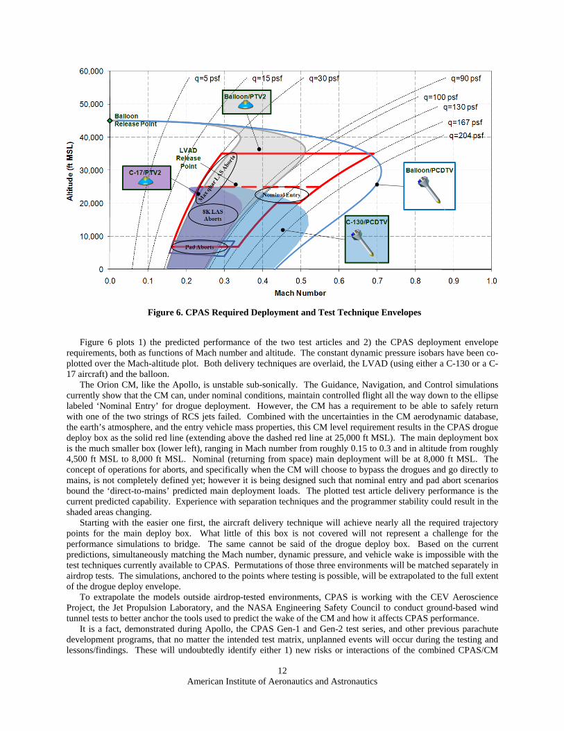
American Institute of Aeronautics and Astronautics
12
Figure 6 plots 1) the predicted performance of the two test articles and 2) the CPAS deployment envelope
requirements, both as functions of Mach number and altitude. The constant dynamic pressure isobars have been co-plotted over the Mach-altitude plot. Both delivery techniques are overlaid, the LVAD (using either a C-130 or a C-17 aircraft) and the balloon.
The Orion CM, like the Apollo, is unstable sub-sonically. The Guidance, Navigation, and Control simulations currently show that the CM can, under nominal conditions, maintain controlled flight all the way down to the ellipse labeled ‘Nominal Entry’ for drogue deployment. However, the CM has a requirement to be able to safely return with one of the two strings of RCS jets failed. Combined with the uncertainties in the CM aerodynamic database, the earth’s atmosphere, and the entry vehicle mass properties, this CM level requirement results in the CPAS drogue deploy box as the solid red line (extending above the dashed red line at 25,000 ft MSL). The main deployment box is the much smaller box (lower left), ranging in Mach number from roughly 0.15 to 0.3 and in altitude from roughly 4,500 ft MSL to 8,000 ft MSL. Nominal (returning from space) main deployment will be at 8,000 ft MSL. The concept of operations for aborts, and specifically when the CM will choose to bypass the drogues and go directly to mains, is not completely defined yet; however it is being designed such that nominal entry and pad abort scenarios bound the ‘direct-to-mains’ predicted main deployment loads. The plotted test article delivery performance is the current predicted capability. Experience with separation techniques and the programmer stability could result in the shaded areas changing.
Starting with the easier one first, the aircraft delivery technique will achieve nearly all the required trajectory points for the main deploy box. What little of this box is not covered will not represent a challenge for the performance simulations to bridge. The same cannot be said of the drogue deploy box. Based on the current predictions, simultaneously matching the Mach number, dynamic pressure, and vehicle wake is impossible with the test techniques currently available to CPAS. Permutations of those three environments will be matched separately in airdrop tests. The simulations, anchored to the points where testing is possible, will be extrapolated to the full extent of the drogue deploy envelope.
To extrapolate the models outside airdrop-tested environments, CPAS is working with the CEV Aeroscience Project, the Jet Propulsion Laboratory, and the NASA Engineering Safety Council to conduct ground-based wind tunnel tests to better anchor the tools used to predict the wake of the CM and how it affects CPAS performance.
It is a fact, demonstrated during Apollo, the CPAS Gen-1 and Gen-2 test series, and other previous parachute development programs, that no matter the intended test matrix, unplanned events will occur during the testing and lessons/findings. These will undoubtedly identify either 1) new risks or interactions of the combined CPAS/CM
Figure 6. CPAS Required Deployment and Test Technique Envelopes

American Institute of Aeronautics and Astronautics
13
performance, and/or 2) the need to repeat tests. For this reason, two of the sixteen planned EDU tests are carried as ‘anomaly resolution’ in hopes of having the opportunity to react to the unknowns of today.
D. Qualification Qualification testing of the CPAS is envisioned to be similar to that of Apollo. Ground tests of materials and
difficult-to-analyze elements of the design, like the main retention system, will be conducted. A total of eight system airdrop tests are currently identified, which will demonstrate repeated nominal deployments as well as the possible permutations of designed-for failures (i.e., one drogue handing off to two mains) for which the CPAS is expected to perform successfully. The test articles used for these system tests will be identical to the flight design in terms of how the CPAS interfaces to the CM and the forebody shape which will generate the same wake the CPAS will experience during flight. In addition to these system-level airdrop tests, each individual canopy design will be airdrop tested to no less than 15% over its respective design limit load, to demonstrate that the structural grid and drag surfaces have positive margin.
The basic tenant persists that the only way to achieve a high level of confidence in the deployment and performance of a large multiple-element parachute system is to test full-scale, at the integrated system level, and to test often. While qualification by testing alone will be fiscally prohibitive, combining reliability growth demonstrated during EDU testing with the qualification system-level tests will provide confidence that the aspects of the performance that cannot be simulated have been thoroughly tested. Analysis must play a large role in the qualification process. The confidence that eight system deployments is enough to demonstrate a complicated design such as the CPAS will come in part from the experience gathered during the EDU testing, both ground and airdrop, where essentially the same design was demonstrated repeatedly. Special attention will be given to aspects of the design that were changed during the EDU testing, as there will be fewer demands from which to draw confidence based on testing alone.
This confidence is in part reflected by the changes implemented during the Gen-1 and Gen-2 testing. This reliability growth will demonstrate how the development testing has identified aspects of the design that were not robust or were poorly understood, allowing the designers to demonstrate solutions prior to beginning qualification testing. A good example of reliability growth is how the reefing rings were retained to the radials. The TSE-CDT-2-2 test sustained a reefing system failure where the lead main canopy skipped second stage and went directly to full-open. The post-test analysis indicated that the assumed asymmetry factor was too low, resulting in an overload of the reefing system. Subsequent to this test, the reefing retention system was modified to show positive margin for the higher loads that were experienced during the test. This change is present in the EDU design for both the drogues and mains. Another example of a change that has improved reliability is how the drogue radial is terminated to attach the suspension line. During one test, a reefing cutter failed to arm. The root cause was determined to be the location of the sear pin for the cutter and the obstacle this joint (where the radial transitioned to the suspension line) represented. The radial termination was redesigned to not be coincident with the end of the cutter. In addition, the cutter arming lanyard was redesigned to have two lanyards of different length. The arming lanyard change was made to give the cutter a chance to align with the pull force in the event of an off angle pull when the canopy skirt reached line stretch.
VI. Verification and Validation The CPAS primary Verification goals are to: 1) Demonstrate that each component and subassembly system is capable of withstanding the mission
environment and functioning properly with adequate margins, within specified tolerances. 2) Demonstrate the total system will function properly in all specified flight modes and that it meets the
interfaces defined between the various components of the Crew Module and the CPAS. Four basic methods will be invoked to satisfy verification: analysis, inspection, demonstration, and test.
Qualification ground and airdrop tests will demonstrate the CPAS meets requirements that cannot be modeled with confidence, events like bag retention for the ascent environment and hardware deployment. Qualification airdrop testing will collect the data that will allow analysts to anchor the inflation and steady-state performance models. However, the actual validation of the system performance will in most cases be performed by analysis using the results from Monte Carlo simulations.15
Figure 7 shows the process to create the analysis and products which verify the CPAS flight design meets the established technical requirements.

American Institute of Aeronautics and Astronautics
14
Not to diminish the importance of any one requirement, two of the most critical and difficult requirements to
verify will be discussed here in more detail. The rate of descent requirement is written for a standard atmosphere with no wind. However, no airdrop test (certainly not a full-scale CPAS airdrop test) is conducted in a no-wind atmosphere. Therefore, while the qualification airdrop test data will be analyzed to confirm that the rate of descent requirement is met throughout the main full-open phase of the test, the verification will be performed using models of the full-open performance. The statistics used to vary the full-open performance will be anchored to applicable EDU and all Qualification airdrop test data. This model will include the transient in rate of descent associated with going from a highly-reefed second stage, in the 10 to 15% range, to full-open, as well as the associated oscillations in performance.
It is very difficult in a system with multiple independently-deployed canopies to be certain whether the canopy that skips the reefing stage will actually be the first to inflate (the intent of a skipped-stage airdrop test). Accordingly, attempting as a primary test objective to demonstrate by test that the skipped-stage load limit is not exceeded at gusset zero almost certainly requires many attempts to collect the data, and as such is prohibitive. The CPAS approach will be similar to that used for the rate of descent, by analysis using models anchored to airdrop test data.
In all cases, confidence in the mean values and associated uncertainty values for the various parameters that predict the parachute performance will be critical. This confidence in the model will come from the cumulative experience of the EDU and Qualification airdrop testing.
VII. Conclusion The CPAS is an extremely lightweight, delicate collection of pieces that absolutely must act together
simultaneously or it will fail with disastrous results. It, alone among the robust pieces of equipment on the Crew Module, must assemble itself in midair at a variety of possible velocities and orientations. When thought of in this fashion, it is easy to see why the single most important goal of design should be simplicity. The best approach for CPAS has been to make architecture and design choices that avoid complexity and when possible eliminate failure
Figure 7. CPAS Verification Flow

American Institute of Aeronautics and Astronautics
15
modes. The design reflects the requirements for redundancy and decoupling failure modes to prevent a common cause from compromising the system performance. Care has been taken to introduce robustness with respect to the parameters outside the control of the CPAS.
It is an interesting problem that large human rated parachute recovery systems face in terms of predicting reliability. Contrary to the previously-stated desire to test full-scale and to test often, it is recognized that almost any program (CPAS included) cannot afford to test often enough to achieve a high score through traditional test-based reliability analysis techniques. The ‘test like you fly’ mantra has been invoked as often as possible, with test techniques developed to span as much of the desired operating envelope as possible. The tests have been instrumented such that the models can be anchored to data in the parachute system design and the number of permutations of possible failures. A risk-based test matrix has been developed to give the system every chance to fail prior to qualification. Care has been taken to inspect the hardware and data post-test to identify any unexpected performance of the system, both making sure the analytical models reflect the system performance, and identifying ‘near misses’ that may indicate a possible likely failure mode without actually failing. These “unknown unknowns” can only be revealed through testing, and only then by diligently reviewing and analyzing the test results.
An important element in the approach CPAS has taken to human rate the design is the methodical documentation and execution of milestone reviews as identified in NPR 7120.5D. Human rating is an integral part of all program activities throughout the life cycle of any system, including design and development, test and verification, program management and control, flight readiness certification, mission operations, and sustaining engineering.
NASA has defined a process for human rating, but this process involves human judgment. This can be frustrating for the system designer who would wish to know what design features must be included, what tests must be conducted, and what level of margins must be demonstrated. Every design has different risks, there will always be judgment involved in balancing the process of “satisfying the mutual constraints of cost, schedule, performance, risk and benefit while addressing the requirement for human safety, human performance, and human health management”. Because there are human lives at stake, there must also be some minimum level of safety below which the pressures of cost and schedule become unpersuasive and human rating becomes unachievable.
The CPAS project has successfully completed the Preliminary Design Review phase of the program, and is working through the EDU design and testing in order to reach the Critical Design Review milestone. All requirements appear to be achievable with the EDU design.
Acknowledgments The authors would like to acknowledge the team that has worked tirelessly since 2006 to take the concept of
implementing parachutes to recover the Orion CEV and create a functioning set of hardware. From the team at Airborne Systems where the actual hardware design, manufacture, packing and rigging takes place; to the team at Jacobs Engineering where the test, analysis, and systems integration to the CM takes place; to the team at Lockheed Martin where negotiations for what the CPAS must accomplish and how it interfaces with the CM occur; to the team of independent experts that have guided the whole process. The names are too numerous to list, but this highly motivated multidisciplinary collection of folks are (forty years after Apollo) demonstrating that parachutes can and will once again be used by NASA to safely return humans from space!

American Institute of Aeronautics and Astronautics
16
References 1 G. Zupp, et. al., “A perspective on the Human‐Rating process of US Crew Module: both Past and Present,” NASA‐SP‐6104, February 1995. 2 C. H. Shivers, “NASA Space Safety Standards and Procedures for Human Rating Requirements,” M09‐0702, 2009. 3 JSC‐65985, Requirements for Human Spaceflight for the Trailing Deployable Aerodynamic Decelerator (TDAD) System, Revision A, January 2011. 4 NPR‐7120.5D, NASA Space Flight Program and Project management Requirements, March 2007. 5 B. West, “Apollo Experience Report – Earth Landing System,” NASA‐TN‐D‐7437, November 1973. 6 Taylor, T., Machin, R., Royall, P., “Developing the Parachute System for NASA’s Orion – An Overview at Inception,” AIAA 2007‐2577, May 2007. 7 NPR 7123.5 8 Knacke, T.W., “Parachute Recovery Systems Design Manual,” U.S. Navy Report NWC TP‐6575, Para Publishing Co., Santa Barbara, CA, 1992. 9 Ray, Eric S., “Measurements of CPAS Main Parachute Rate of Descent,” 21st AIAA Aerodynamic Decelerator Systems Conference, May 2011. 10 Bledsoe, K., Englert, M., Morris, A., Olmstead, R., “Overview of the Crew Exploration Vehicle Parachute Assembly System (CPAS) Generation I Main and Cluster Development Test Results,”AIAA‐2009‐2940, May 2009. 11 Bledsoe, K., Englert, M., Morris, A., Olmstead, R., “Overview of the Crew Exploration Vehicle Parachute Assembly System (CPAS) Generation I Drogue and Pilot Development Test Results,” AIAA‐2009‐2939, May 2009. 12 Machin, R., Evans, CT., “Cluster Development Test 2 and Assessment of a Failed Test,” AIAA‐2009‐16911, May 2009. 13 Ray, E., “Measurement of CPAS Main Parachute Rate of Descent,” 21st AIAA Aerodynamic Decelerator Systems Technology Conference, May 2011. 14 Ray, E., Bretz, D., “Photogrammetric Analysis of CPAS Main Parachutes,” 21st AIAA Aerodynamic Decelerator Systems Technology Conference, May 2011. 15 Morris, A., Olson, L., “Verification and Validation Plan for Flight Performance Requirements on the CEV Parachute Assembly System,” 21st AIAA Aerodynamic Decelerator Systems Technology Conference, May 2011.