Dynamic Mesh CFD Simulations of Orion Parachute … · Dynamic Mesh CFD Simulations of Orion...
5
Dynamic Mesh CFD Simulations of Orion Parachute Pendulum Motion During Atmospheric Entry Logan D. Halstrom * Department of Mechanical and Aerospace Engineering University of California, Davis, CA 95616 Alan M. Schwing † Applied Aeroscience and CFD Branch NASA Johnson Space Center, Houston, TX, 77584 Stephen K. Robinson ‡ Department of Mechanical and Aerospace Engineering University of California, Davis, CA 95616 This paper demonstrates the usage of computational fluid dynamics to study the effects of pendulum motion dynamics of the NASAs Orion Multi-Purpose Crew Vehicle parachute system on the stability of the vehicles atmospheric entry and decent. Significant computa- tional fluid dynamics testing has already been performed at NASAs Johnson Space Center, but this study sought to investigate the effect of bulk motion of the parachute, such as pitching, on the induced aerodynamic forces. Simulations were performed with a moving grid geometry oscillating according to the parameters observed in flight tests. As with the previous simulations, OVERFLOW computational fluid dynamics tool is used with the assumption of rigid, non-permeable geometry. Comparison to parachute wind tunnel tests is included for a preliminary validation of the dynamic mesh model. Results show quali- tative differences in the flow fields of the static and dynamic simulations and quantitative differences in the induced aerodynamic forces, suggesting that dynamic mesh modeling of the parachute pendulum motion may uncover additional dynamic effects. Nomenclature θ max Maxumum angle of pendulum oscillation f Frequency of pendulum oscillation I. Introduction The Orion Multi-Purpose Crew Vehicle (MPCV) utilizes a 3-parachute system for subsonic deceleration during atmospheric reentry. Flight testing has demonstrated that this deceleration system has the potential of exhibiting dynamic instability when only two of three parachutes deploy. Under this failure mode, the flight vehicle/parachute system can enter oscillatory pendulum motion, an unstable condition that could pose potential hazard to the flight vehicle and crew. 1 Various testing methods have been employed to better understanding and mitigate the nature of this instability, including drop testing, wind tunnel testing, and Computational Fluid Dynamics (CFD). Static * Graduate Student † Engineer ‡ Professor 1 of 5 American Institute of Aeronautics and Astronautics https://ntrs.nasa.gov/search.jsp?R=20150020945 2018-06-19T21:13:52+00:00Z
Transcript of Dynamic Mesh CFD Simulations of Orion Parachute … · Dynamic Mesh CFD Simulations of Orion...

Dynamic Mesh CFD Simulations of Orion Parachute
Pendulum Motion During Atmospheric Entry
Logan D. Halstrom∗
Department of Mechanical and Aerospace Engineering
University of California, Davis, CA 95616
Alan M. Schwing†
Applied Aeroscience and CFD Branch
NASA Johnson Space Center, Houston, TX, 77584
Stephen K. Robinson ‡
Department of Mechanical and Aerospace Engineering
University of California, Davis, CA 95616
This paper demonstrates the usage of computational fluid dynamics to study the effectsof pendulum motion dynamics of the NASAs Orion Multi-Purpose Crew Vehicle parachutesystem on the stability of the vehicles atmospheric entry and decent. Significant computa-tional fluid dynamics testing has already been performed at NASAs Johnson Space Center,but this study sought to investigate the effect of bulk motion of the parachute, such aspitching, on the induced aerodynamic forces. Simulations were performed with a movinggrid geometry oscillating according to the parameters observed in flight tests. As withthe previous simulations, OVERFLOW computational fluid dynamics tool is used with theassumption of rigid, non-permeable geometry. Comparison to parachute wind tunnel testsis included for a preliminary validation of the dynamic mesh model. Results show quali-tative differences in the flow fields of the static and dynamic simulations and quantitativedifferences in the induced aerodynamic forces, suggesting that dynamic mesh modeling ofthe parachute pendulum motion may uncover additional dynamic effects.
Nomenclature
θmax Maxumum angle of pendulum oscillationf Frequency of pendulum oscillation
I. Introduction
The Orion Multi-Purpose Crew Vehicle (MPCV) utilizes a 3-parachute system for subsonic decelerationduring atmospheric reentry. Flight testing has demonstrated that this deceleration system has the potentialof exhibiting dynamic instability when only two of three parachutes deploy. Under this failure mode, theflight vehicle/parachute system can enter oscillatory pendulum motion, an unstable condition that couldpose potential hazard to the flight vehicle and crew.1
Various testing methods have been employed to better understanding and mitigate the nature of thisinstability, including drop testing, wind tunnel testing, and Computational Fluid Dynamics (CFD). Static
∗Graduate Student†Engineer‡Professor
1 of 5
American Institute of Aeronautics and Astronautics
https://ntrs.nasa.gov/search.jsp?R=20150020945 2018-06-19T21:13:52+00:00Z
CFD simulations were performed using the OVERFLOW flow solver, under the assumptions of a rigid,non-permeable geometry. Simulations were for a single parachute and sought to demonstrate static stabilitycharacteristics for a parachute with no bulk motion (such as pitching).3
However, pendulum motion is a result of rate-dependent, dynamic forces, and it was of interest to theauthors to investigate the effect of parachute motion on the CFD results. For this purpose, a movinggeometry CFD simulation was performed, where the existing grid systems were modified to allow pendulummotion according to a prescribed equation during the simulation.
II. Computational Methods
CFD simulations were performed using the OVERFLOW flow solver. It is an implicit Navier-Stokessolver, which employs finite-differencing methods on structured, overset grids.4
Solutions were derived in a two-step process, first resolving the time-accurate flow over the static (non-pitching) parachute, then initiating movement and acquiring dynamic data after transient effects and thestatic wake had dissipated. Similar to the static CFD cases, the two-equation Shear Stress Transportturbulence model by Menter was employed.2
As with the static cases, the simulation Mach number was scaled from the MPCV flight condition ofMach 0.03 at a dynamic pressure of around 1.3 [psf] to Mach 0.15 to improve numerical stability and avoidlow-Mach preconditioning.3 Solutions for both Mach numbers were compared and demonstrated similaritybetween these freestream conditions. To achieve appropriate velocity scaling, the rate of the prescribedpendulum motion was also scaled proportionately, as detailed in Section III.
III. Prescribed Pendulum Motion
To simulate pendulum motion of a single parachute, OVERFLOW flow solvers Geometry ManipulationProtocol (GMP) tool was utilized to prescribe the motion of the parachute geometry to a simple, harmonicmotion function.7 Operating in I6DOF=2 mode activates GMP, allowing geometry configurations andprescribed motion commands to be read from the Extensible Markup Language (XML) files ‘Config.xml and‘Scenario.xml.
For the primary simulation, the parachute geometry and the box grid immediately surrounding theparachute were prescribed to oscillate about the Orion MPCV attachment point at the frequency and am-plitude of oscillation observed in flight tests of the MPCV decent system. The GMP XML files specificallyassign the angular rate of the geometry, which is detailed for this case in Eqn. (1).
θ̇(t) = θmax · 2πf · cos(2πf · t) (1)
where θ̇ is the pitch rate of the parachute, θmax is the maximum angular amplitude of the oscillation, f isthe frequency of the oscillation in Hertz, and t is the simulation time.
As previously mentioned in Section II, the Mach number (and thus velocity) of the parachute was scaledup by a factor of five for numerical solver considerations. This required that the frequency of oscillationof the parachute system also be scaled by that same factor so that the dynamic pressure of the parachutewould scale accordingly, preserving the similarity parameters of the problem.
IV. Grid Generation and Movement
Grid motion was accomplished in OVERFLOW using a prescribed function of oscillation. This requiredsetting new rules for cell blanking and creating data processing scripts to account for the relative motion ofthe grids within the simulation.
IV.A. Grid Generation
Grids for dynamic CFD simulations were developed from the grid scripts utilized in static cases, which aredeveloped using Chimera Grid Tools (CGT).3 Overset grids proved to be beneficial for representing movingparachute geometry, not only because of the complexity of the interaction of the many structures within thegrid system but also due to the need to recalculate overset interpolation stencils during the simulation afterrelative grid motion.
2 of 5
American Institute of Aeronautics and Astronautics
IV.B. Domain Connectivity Function
Unlike the static CFD simulations, PEGASUS5 domain connectivity software could not be used for cellblanking as it is not built into OVERFLOW and domain connectivity must be recalculated within thesimulation for moving geometries.5 Instead, the Domain Connectivity Function (DFC) was utilized toperform hole cutting and calculation of interpolation stencils.6
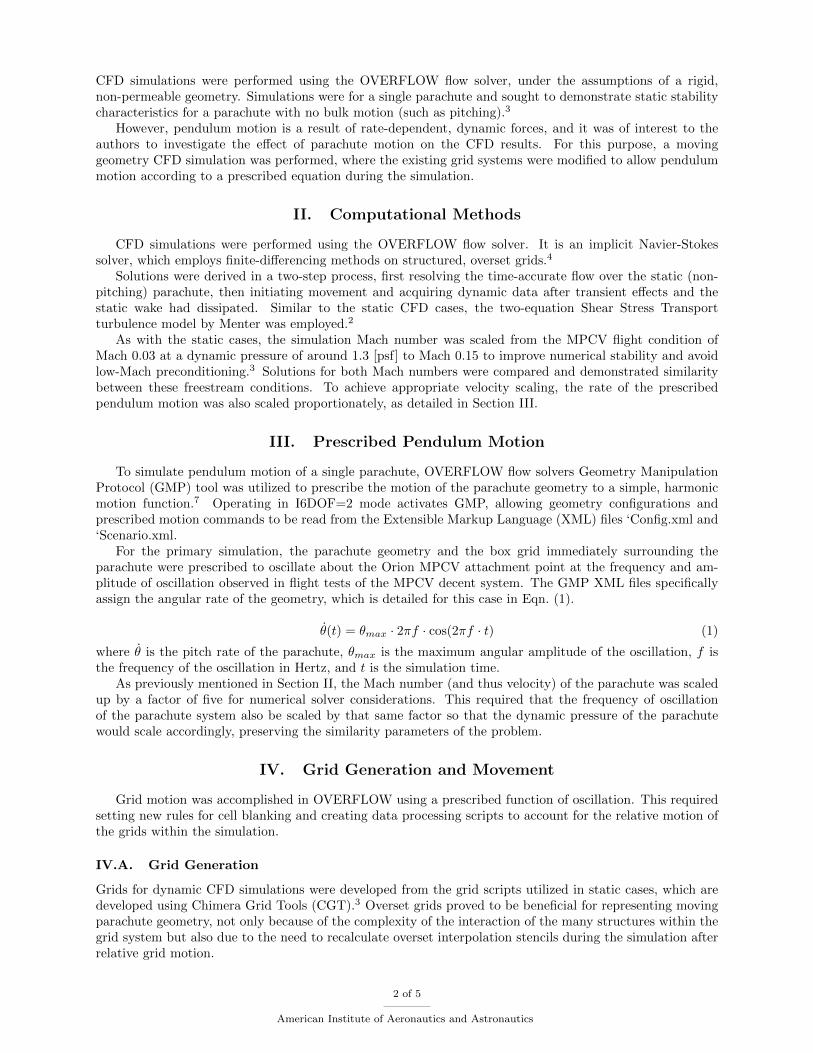
Hole cutting was accomplished by extracting surfaces from the volume grids of each parachute segment,creating “phantom” cutter surfaces (See Fig. 1). X-raying these surfaces and using a zero-cutting distance al-lowed for almost exact control of interpolation regions and allowed for fine cutting within the small parachutegaps and expansive cutting elsewhere around the segment.
Figure 1. Phantom cutter grids for single chute segment (left) and the final half cross-sectional view of DCF holecutting for the parachute grid system )right
IV.C. Data Post-Processing
A series of data post-processing scripts were written in Python to condition the raw data produced bythe OVERFLOW flow solver. Since OVERFLOW does not bookkeep the relative motion of grids for non-dimensionalization parameters, the OVERFLOW output force coefficients were corrected for the actualdynamic pressure of the parachute due to freestream velocity as well as its oscillatory velocity.
Velocity of oscillation was calculated according to the equations of prescribed motion, which also allowedthe calculation of the effective angle of attack of the parachute.
V. Wind Tunnel Test
For validating the dynamic force simulation capability of the moving CFD model, results were comparedto tests of a one-third scale MPCV parachute in the National Full-scale Aerodynamic Complex (NFAC)80x120 wind tunnel. In this test, the parachute was secured by its risers upstream of the parachute, andmaneuvered by tethers attached to the aft vent. For the dynamic tests, the parachute was released at thevent an allowed to precess about the test section of the wind tunnel. Load forces on the risers were recorded,allowing the direct calculation of aerodynamic coefficients for comparison with dynamic CFD.,89
VI. Results and Comparisons
After initial calibration and a time step sensitivity study, multiple simulations were performed with avariety of maximum oscillation angles to vary the tangential velocity of the parachute during pendulummotion.
3 of 5
American Institute of Aeronautics and Astronautics

VI.A. Dynamic CFD Results
The purpose of this work was to demonstrate the differences, if any, between the CFD results for static andmoving parachute geometries. Fig. 2 represents the flow surrounding the parachute at an angle of attack ofα = 0o. For the static case, flow is approaching the parachute head-on, and a symmetric wake is produced.For the dynamic case, the parachute has just passed its maximum amplitude angle and is traveling backtoward the center of its oscillation. The vector sum of the freestream velocity and the tangential velocity ofoscillation is such that the effective velocity vector of the moving parachute is also head-on into the chute.
Figure 2. Flow visualizations for static (left) and dynamic (right) CFD simulations, each at an angle of attack of α = 0o
Though the two parachute flow fields are at the same angle of attack, their appearances are significantlydifferent, with a less resolved wake and an off-body vortex being generated in the dynamic case, suggestingthat there are flow effects purely due to the dynamics of the parachute oscillation.
Figure 3. Dynamic and static CFD axial and normal force coefficient comparisons for simulations of various amplitudes
To more directly compare the contributions of the static and dynamic forces, the static force at a giveninstant was subtracted from the dynamic force to produce a representation of the dynamic addition. Thesestatic and dynamic force coefficients are compared in Fig. 3. Observing the θmax = 25o case, it can be seenthat the dynamic contribution varies from approximately onethird the magnitude of the static baseline (axialforce of the parachute is negative, so the negative CA axis is increasing magnitude) to on the same orderas the static forces. In the case of normal force coefficient, it can be seen that the dynamic effects trulydominate the periodic force behavior.
4 of 5
American Institute of Aeronautics and Astronautics
VI.B. Validation
CFD results were also compared to those of the NFAC wind tunnel test to determine if the dynamic effectssimulated by the CFD were comparable to those observed in actual flow. Though the simplified oscillatorypath of the CFD simulation proved to be unrepresentative of the attitude track of the parachute in the windtunnel test, general trends appear similar between the CFD and the wind tunnel.
VII. Conclusions and Future Work
This work describes the process for performing a dynamic, moving grid CFD simulation for the OrionMPCV parachute. The flows of the dynamic simulations were shown to be notably different from theirstatic CFD counterparts, both in qualitative flow characteristics and in quantitative aerodynamic forcecomparisons. More study is needed to determine where these effects are significant in terms of modeling theinstability of the Orion MPCV parachute system.
Preliminary validation of the dynamic CFD model was accomplished by comparison to NFAC wind tunneltest data. To improve this comparison, a prescribed motion CFD simulation could be performed that moredirectly followed the track of the parachute in the wind tunnel.
It is also of interest to determine the effects of forced motion on the results of these simulations. Sincemotion in these simulations is prescribed, some of the dynamic effects could be a result of forced oscillation. Asix degree of freedom simulation, where parachute motion is influenced by the calculated aerodynamic forces,would help determine which effects, if any, are due to the forced nature of the motion in the simulationsdescribed in this paper.
Acknowledgments
MPCV Pendulum Action Team, UC Davis
References
1E. S. Ray and R. A. Machin, “Pendulum Motion in Main Parachute Clusters,” in 23rd AIAA Aerodynamic DeceleratorSystems Technology Conference, Submitted, 2015.
2F. R. Menter and Christopher L. Rumsey, “Assessment of Two-Equation Turbulence Models for Transonic Flows,” in 25thAIAA Fluid Dynamics Conference, Submitted, 1994.
3J. S. Greathouse and A. M. Schwing, “Study of Geometric Porosity on Static Stability and Drag using Computational FluidDynamics for Rigid Parachute Shapes,” in 23rd AIAA Aerodynamic Decelerator Systems Technology Conference, Submitted,2015.
4R. H. Nichols, R. W. Tramel, and P. G. Buning, Solver and Turbulence Model Upgrades to OVERFLOW 2 for Unsteadyand High-Speed Applications, No. AIAA 2006-2824, 2006.
5S. E. Rogers, K. Roth, M. Field, S. M. Nash, M. D. Baker, J. P. Slotnick, M. Whitlock, L. Beach, and H. V. Cao, “Advancesin Overset CFD Processes Applied to Subsonic High-Lift Aircraft”, No. AIAA 2000-4216, 2000.
6W. M. Chan, N. Kim, and S. A. Pandya, “Advances in Domain Connectivity for Overset Grids Using the X-rays Approach,”in Seventh International Conference on Computational Fluid Dynamics, Submitted, 2012.
7S. M. Murman, W. M. Chan, M. J. Aftosmis, and R. L. Meakin, “An Interface for Specifying Rigid-Body Motions forCFD Applications,” AIAA Paper 2003-1237, 2003.
8J. M. Macha and R. J. Buffington, “Wall-Interference Corrections for Parachutes in a Closed Wind Tunnel,” Journal ofAircraft, Vol. 27, No. 4, pp. 320-325, April 1990.
9nfac test report?
5 of 5
American Institute of Aeronautics and Astronautics
![Structural Mechanics Computation of the Orion Spacecraft ... · Structural mechanics equations - Spatial Discretization Finite element method Parachute configuration [1] Mach number](https://static.fdocuments.in/doc/165x107/5e88c2d72665747f7a287fd3/structural-mechanics-computation-of-the-orion-spacecraft-structural-mechanics.jpg)