HP Environment: Product End-of-Life Disassembly instructionsh22235. · Product End-of-Life...
6
Product End-of-Life Disassembly Instructions Product Category: Inkjet Printer Marketing Name / Model: [List multiple models if applicable.] HP Officejet Pro 8600 e-AiO printer Purpose: The document is intended for use by end-of-life recyclers or treatment facilities. It provides the basic instructions for the disassembly of HP products to remove components and materials requiring selective treatment, as defined by EU directive 2002/96/EC, Waste Electrical and Electronic Equipment (WEEE). 1.0 Items Requiring Selective Treatment 1.1 Items listed below are classified as requiring selective treatment. 1.2 Enter the quantity of items contained within the product which require selective treatment in the right column, as applicable. Item Description Notes Quantity of items included in product Printed Circuit Boards (PCB) or Printed Circuit Assemblies (PCA) Printing Mechanism, Scanner bed, Carriages, Control panel; Surface area > 10 sq. cm Batteries Main PCA; Lithium coin style batteries Mercury-containing components 0 Liquid Crystal Displays (LCD) with a surface greater than 100 sq cm Cathode Ray Tubes (CRT) Capacitors / condensers (Containing PCB/PCT) Electrolytic Capacitors / Condensers measuring greater than 2.5 cm in diameter or height Located within external power supply External electrical cables and cords Connected to external power supply Gas Discharge Lamps Plastics containing Brominated Flame Retardants Components and parts containing toner and ink, including liquids, semi-liquids (gel/paste) and toner Components and waste containing asbestos Components, parts and materials containing refractory ceramic fibers Components, parts and materials containing radioactive substances 2.0 Tools Required List the type and size of the tools that would typically be used to disassemble the product to a point where components and materials requiring selective treatment can be removed. EL-MF877-00 Page 1 Template Revision A
-
Upload
doankhuong -
Category
Documents
-
view
226 -
download
2
Transcript of HP Environment: Product End-of-Life Disassembly instructionsh22235. · Product End-of-Life...

Product End-of-Life Disassembly Instructions Product Category: Inkjet Printer
Marketing Name / Model: [List multiple models if applicable.] HP Officejet Pro 8600 e-AiO printer Purpose: The document is intended for use by end-of-life recyclers or treatment facilities. It provides the basic instructions for the disassembly of HP products to remove components and materials requiring selective treatment, as defined by EU directive 2002/96/EC, Waste Electrical and Electronic Equipment (WEEE). 1.0 Items Requiring Selective Treatment 1.1 Items listed below are classified as requiring selective treatment. 1.2 Enter the quantity of items contained within the product which require selective treatment in the right column, as applicable.
Item Description Notes Quantity of items included in product
Printed Circuit Boards (PCB) or Printed Circuit Assemblies (PCA)
Printing Mechanism, Scanner bed, Carriages, Control panel; Surface area > 10 sq. cm
Batteries Main PCA; Lithium coin style batteries Mercury-containing components 0 Liquid Crystal Displays (LCD) with a surface greater than 100 sq cm
Cathode Ray Tubes (CRT) Capacitors / condensers (Containing PCB/PCT) Electrolytic Capacitors / Condensers measuring greater than 2.5 cm in diameter or height
Located within external power supply
External electrical cables and cords Connected to external power supply Gas Discharge Lamps Plastics containing Brominated Flame Retardants Components and parts containing toner and ink, including liquids, semi-liquids (gel/paste) and toner
Components and waste containing asbestos Components, parts and materials containing refractory ceramic fibers
Components, parts and materials containing radioactive substances
2.0 Tools Required List the type and size of the tools that would typically be used to disassemble the product to a point where components and materials requiring selective treatment can be removed.
EL-MF877-00 Page 1 Template Revision A
Tool Description Tool Size (if applicable)
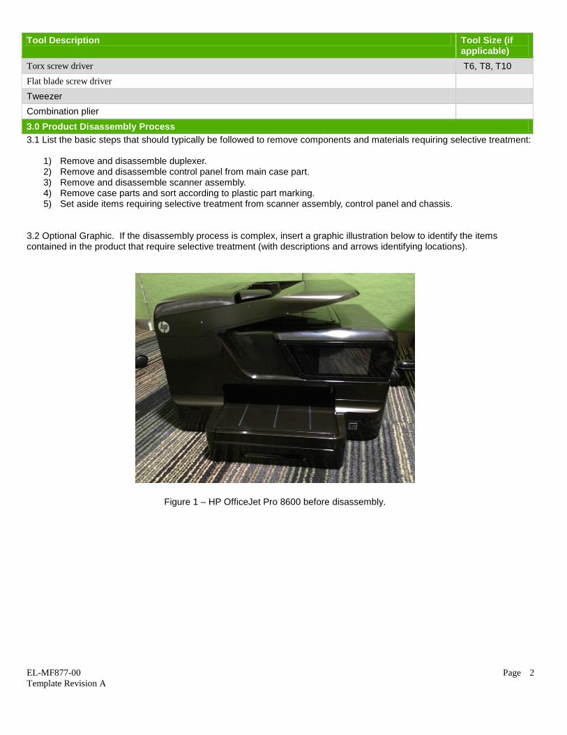
Torx screw driver T6, T8, T10 Flat blade screw driver Tweezer Combination plier 3.0 Product Disassembly Process 3.1 List the basic steps that should typically be followed to remove components and materials requiring selective treatment:
1) Remove and disassemble duplexer. 2) Remove and disassemble control panel from main case part. 3) Remove and disassemble scanner assembly. 4) Remove case parts and sort according to plastic part marking. 5) Set aside items requiring selective treatment from scanner assembly, control panel and chassis.
3.2 Optional Graphic. If the disassembly process is complex, insert a graphic illustration below to identify the items contained in the product that require selective treatment (with descriptions and arrows identifying locations).
Figure 1 – HP OfficeJet Pro 8600 before disassembly.
EL-MF877-00 Page 2 Template Revision A

Figure 2 – To remove duplexer: press the connection button (refer to red arrows) and detach it from printer base. Disassemble duplexer with care, and set aside plastic parts according to plastic code marking.
Figure 3 – To remove control panel: unscrew tied at printer front case under rubber (refer to red circle), detach connection, and remove control panel from printer case. Also remove cable connecting control panel. Disassemble control panel with care, and set aside item required selective treatment.
EL-MF877-00 Page 3 Template Revision A

Figure 4 & 5 - To remove scanner assembly: unscrew on the front case, back case (refer to red circles), and behind control panel assembly, give a push underneath the scanner glass part. Open up the scanner assembly from printing mechanism, gently remove cable connecting scanner assembly and the main PCA. Disassemble scanner with care, and set aside all items required selective treatment. Also, set aside plastic parts according to plastic marking code.
Figure 6 – To remove case part: detach connection at bottom of printer (refer to red arrows), dismantle case parts from the front and both sides of the printer.
EL-MF877-00 Page 4 Template Revision A

Figure 7 - Remove main PCA from printing mechanism by unscrewing and detaching all connected cables and wires (refer to red arrows). Gently pull out and remove all internal cords. Remove speaker located at the side of main PCA.
Figure 8 – To remove chassis: remove carriage assembly (refer to blue circle), followed by the chassis by removing all screws on chassis and assembly.. Set aside all PCAs for selective treatment.
EL-MF877-00 Page 5 Template Revision A

Figure 9: Remove power supply and motors located at the bottom of chassis. Gently remove wires and cables connecting motors with chassis.
Figure 10: Printer base after disassembly.
EL-MF877-00 Page 6 Template Revision A