HP 6125 Blade Switch Serieskmcs-service.austin.hp.com/km-ext/kmcsdirect/emr_na-c03500152-2.pdf · 1...
84
HP 6125 Blade Switch Series ACL and QoS Configuration Guide Part number: 5998-3159 Software version: Release 2103 Document version: 6W100-20120907
-
Upload
nguyentruc -
Category
Documents
-
view
233 -
download
0
Transcript of HP 6125 Blade Switch Serieskmcs-service.austin.hp.com/km-ext/kmcsdirect/emr_na-c03500152-2.pdf · 1...

HP 6125 Blade Switch Series ACL and QoS Configuration Guide
Part number: 5998-3159
Software version: Release 2103
Document version: 6W100-20120907

Legal and notice information
© Copyright 2012 Hewlett-Packard Development Company, L.P.
No part of this documentation may be reproduced or transmitted in any form or by any means without prior written consent of Hewlett-Packard Development Company, L.P.
The information contained herein is subject to change without notice.
HEWLETT-PACKARD COMPANY MAKES NO WARRANTY OF ANY KIND WITH REGARD TO THIS MATERIAL, INCLUDING, BUT NOT LIMITED TO, THE IMPLIED WARRANTIES OF MERCHANTABILITY AND FITNESS FOR A PARTICULAR PURPOSE. Hewlett-Packard shall not be liable for errors contained herein or for incidental or consequential damages in connection with the furnishing, performance, or use of this material.
The only warranties for HP products and services are set forth in the express warranty statements accompanying such products and services. Nothing herein should be construed as constituting an additional warranty. HP shall not be liable for technical or editorial errors or omissions contained herein.

i
Contents
Configuring ACLs ························································································································································· 1 Overview ············································································································································································ 1
Applications on the switch ······································································································································ 1 ACL categories ························································································································································· 1 Numbering and naming ACLs ································································································································ 1 Match order ······························································································································································ 2 ACL rule comments and rule range remarks ········································································································· 3 ACL rule numbering ················································································································································· 3 Fragments filtering with ACLs ·································································································································· 3
ACL configuration task list ················································································································································ 3 Configuring a time range ················································································································································· 4 Configuring a basic ACL ·················································································································································· 4
Configuring an IPv4 basic ACL ······························································································································ 4 Configuring an IPv6 basic ACL ······························································································································ 5
Configuring an advanced ACL ········································································································································ 6 Configuring an IPv4 advanced ACL······················································································································· 6 Configuring an IPv6 advanced ACL······················································································································· 7
Configuring an Ethernet frame header ACL ··················································································································· 9 Copying an ACL ······························································································································································· 9
Copying an IPv4 ACL ··········································································································································· 10 Copying an IPv6 ACL ··········································································································································· 10
Packet filtering with ACLs ·············································································································································· 10 Applying an IPv4 or Ethernet frame header ACL for packet filtering ······························································ 10 Applying an IPv6 ACL for packet filtering ·········································································································· 10
Displaying and maintaining ACLs ································································································································ 11 Configuration example of using ACL for device management ················································································· 11
Network requirements ··········································································································································· 11 Configuration procedure ······································································································································ 12
IPv4 packet filtering configuration example ················································································································ 13 Network requirements ··········································································································································· 13 Configuration procedure ······································································································································ 13
IPv6 packet filtering configuration example ················································································································ 14 Network requirements ··········································································································································· 14 Configuration procedure ······································································································································ 14
QoS overview ····························································································································································· 15 QoS service models ······················································································································································· 15
Best-effort service model ······································································································································· 15 IntServ model ························································································································································· 15 DiffServ model ······················································································································································· 15
QoS techniques ······························································································································································ 16
QoS configuration approaches································································································································· 17 MQC approach ····························································································································································· 17 Non-MQC approach ····················································································································································· 17
Configuring a QoS policy ········································································································································· 18 Overview ········································································································································································· 18 Defining a class ······························································································································································ 18
Configuration restrictions and guidelines ··········································································································· 19

ii
Configuration procedure ······································································································································ 19 Defining a traffic behavior ············································································································································ 20 Defining a policy ···························································································································································· 21
Configuration restrictions and guidelines ··········································································································· 21 Configuration procedure ······································································································································ 21
Applying the QoS policy ··············································································································································· 21 Applying the QoS policy to an interface ············································································································ 22 Applying the QoS policy to online users ············································································································ 22 Applying the QoS policy to a VLAN ··················································································································· 23 Applying the QoS policy globally ······················································································································· 23
Displaying and maintaining QoS policies ·················································································································· 23
Configuring priority mapping ··································································································································· 25 Overview ········································································································································································· 25
Types of priorities ·················································································································································· 25 Priority mapping tables ········································································································································· 25 Priority trust mode on a port ································································································································· 26 Priority mapping procedure ································································································································· 26
Configuration guidelines ··············································································································································· 27 Configuring a priority mapping table ·························································································································· 27 Configuring a port to trust packet priority for priority mapping ··············································································· 27 Changing the port priority of an interface ·················································································································· 27 Displaying priority mappings ······································································································································· 28 Priority trust mode configuration example ··················································································································· 28
Network requirements ··········································································································································· 28 Configuration procedure ······································································································································ 29
Priority mapping table and priority marking configuration example ······································································· 29 Network requirements ··········································································································································· 29 Configuration procedure ······································································································································ 30
Configuring traffic policing, traffic shaping, and line rate ····················································································· 32 Overview ········································································································································································· 32
Traffic evaluation and token buckets ··················································································································· 32 Traffic policing ······················································································································································· 33 Traffic shaping ······················································································································································· 34 Line rate ·································································································································································· 34
Configuring traffic policing ··········································································································································· 35 Configuration restrictions and guidelines ··········································································································· 35 Configuration procedure ······································································································································ 35
Configuring GTS ···························································································································································· 36 Configuring the line rate ··············································································································································· 36 Displaying and maintaining traffic policing, GTS, and line rate ·············································································· 37 Traffic policing configuration example ························································································································ 37
Network requirements ··········································································································································· 37 Configuration procedures ····································································································································· 38
Configuring congestion management ······················································································································ 40 Overview ········································································································································································· 40 Congestion management techniques ··························································································································· 40
SP queuing ····························································································································································· 40 WRR queuing ························································································································································· 41 WFQ queuing ························································································································································ 42 SP+WRR queuing ·················································································································································· 43 SP+WFQ queuing ················································································································································· 43
Configuring SP queuing ················································································································································ 43 Configuration procedure ······································································································································ 43

iii
Configuration example ········································································································································· 43 Configuring WRR queuing ············································································································································ 44
Configuration procedure ······································································································································ 44 Configuration example ········································································································································· 44
Configuring WFQ queuing ··········································································································································· 45 Configuration procedure ······································································································································ 45 Configuration example ········································································································································· 46
Configuring SP+WRR queuing ····································································································································· 46 Configuration procedure ······································································································································ 46 Configuration example ········································································································································· 47
Configuring SP+WFQ queuing ···································································································································· 47 Configuration procedure ······································································································································ 47 Configuration example ········································································································································· 48
Configuring congestion avoidance ··························································································································· 49 Overview ········································································································································································· 49
Tail drop ································································································································································· 49 RED and WRED ····················································································································································· 49
Introduction to WRED configuration ···························································································································· 49 Configuring WRED ························································································································································ 50
Configuration procedure ······································································································································ 50 Configuration examples········································································································································ 50
Displaying and maintaining WRED ····························································································································· 51
Configuring traffic filtering ········································································································································ 52 Configuration procedure ··············································································································································· 52 Traffic filtering configuration example ························································································································· 53
Network requirements ··········································································································································· 53 Configuration procedure ······································································································································ 53
Configuring priority marking ····································································································································· 54 Configuration procedure ··············································································································································· 54 Local precedence re-marking configuration example ································································································ 55
Network requirements ··········································································································································· 55 Configuration procedure ······································································································································ 56
Local QoS ID marking configuration example ············································································································ 57
Configuring traffic redirecting ··································································································································· 59 Configuration restrictions and guidelines ···················································································································· 59 Configuration procedure ··············································································································································· 59 Redirect-to-next hop configuration example ················································································································ 60
Network requirements ··········································································································································· 60 Configuration procedure ······································································································································ 60
Configuring aggregate CAR ····································································································································· 62 Overview ········································································································································································· 62 Configuring aggregate CAR ········································································································································· 62
Configuration restrictions and guidelines ··········································································································· 62 Configuration procedure ······································································································································ 62
Displaying and maintaining aggregate CAR configuration ······················································································ 63 Aggregate CAR configuration example ······················································································································ 63
Network requirements ··········································································································································· 63 Configuration procedure ······································································································································ 63
Configuring class-based accounting ························································································································· 65 Configuration procedure ··············································································································································· 65 Displaying and maintaining traffic accounting ··········································································································· 65

iv
Class-based accounting configuration example ········································································································· 66 Network requirements ··········································································································································· 66 Configuration procedure ······································································································································ 66
Configuring burst ······················································································································································· 68 Configuration prerequisites ··········································································································································· 68 Configuration procedure ··············································································································································· 68 Burst configuration example ········································································································································· 68
Network requirements ··········································································································································· 68 Configuration procedure ······································································································································ 69
Appendix A Default priority mapping tables ··········································································································· 70 Uncolored priority mapping tables ······························································································································ 70
Appendix B Packet precedences ······························································································································ 71 IP precedence and DSCP values ·································································································································· 71 802.1p priority ······························································································································································ 72
Support and other resources ····································································································································· 74 Contacting HP ································································································································································ 74
Subscription service ·············································································································································· 74 Related information ························································································································································ 74
Documents ······························································································································································ 74 Websites ································································································································································· 74
Conventions ···································································································································································· 75
Index ··········································································································································································· 77

1
Configuring ACLs
Unless otherwise stated, ACLs refer to both IPv4 and IPv6 ACLs throughout this document.
Overview An access control list (ACL) is a set of rules (or permit or deny statements) for identifying traffic based on criteria such as source IP address, destination IP address, and port number.
ACLs are primarily used for packet filtering. A packet filter drops packets that match a deny rule and permits packets that match a permit rule. ACLs are also used by many modules, QoS and IP routing for example, for traffic classification and identification.
Applications on the switch An ACL is implemented in hardware or software, depending on the module that uses it. If the module, the packet filter or QoS module for example, is implemented in hardware, the ACL is applied to hardware to process traffic. If the module, the routing or user interface access control module (Telnet, SNMP, or web) for example, is implemented in software, the ACL is applied to software to process traffic.
The user interface access control module denies packets that do not match any ACL. Some modules, QoS for example, ignore the permit or deny action in ACL rules and do not base their drop or forwarding decisions on the action set in ACL rules. See the specified module for information about ACL application.
ACL categories
Category ACL number IP version Match criteria
Basic ACLs 2000 to 2999
IPv4 Source IPv4 address
IPv6 Source IPv6 address
Advanced ACLs 3000 to 3999
IPv4 Source IPv4 address, destination IPv4 address, packet priority, protocols over IPv4, and other Layer 3 and Layer 4 header fields
IPv6 Source IPv6 address, destination IPv6 address, packet priority, protocols over IPv6, and other Layer 3 and Layer 4 header fields
Ethernet frame header ACLs
4000 to 4999
IPv4 and IPv6
Layer 2 header fields, such as source and destination MAC addresses, 802.1p priority, and link layer protocol type
Numbering and naming ACLs Each ACL category has a unique range of ACL numbers. When creating an ACL, you must assign it a number. In addition, you can assign the ACL a name for ease of identification. After creating an ACL with a name, you cannot rename it or delete its name.
For an Ethernet frame header ACL, the ACL number and name must be globally unique. For an IPv4 basic or advanced ACLs, its ACL number and name must be unique among all IPv4 ACLs, and for an IPv6

2
basic or advanced ACL, its ACL number and name must be unique among all IPv6 ACLs. You can assign an IPv4 ACL and an IPv6 ACL the same number and name.
Match order The rules in an ACL are sorted in a specific order. When a packet matches a rule, the device stops the match process and performs the action defined in the rule. If an ACL contains overlapping or conflicting rules, the matching result and action to take depend on the rule order.
The following ACL match orders are available:
• config—Sorts ACL rules in ascending order of rule ID. A rule with a lower ID is matched before a rule with a higher ID. If you use this approach, carefully check the rules and their order.
• auto—Sorts ACL rules in depth-first order. Depth-first ordering guarantees that any subset of a rule is always matched before the rule. Table 1 lists the sequence of tie breakers that depth-first ordering uses to sort rules for each type of ACL.
Table 1 Sort ACL rules in depth-first order
ACL category Sequence of tie breakers
IPv4 basic ACL
1. VPN instance 2. More 0s in the source IP address wildcard (more 0s means a narrower IP
address range) 3. Rule configured earlier
IPv4 advanced ACL
1. VPN instance 2. Specific protocol type rather than IP (IP represents any protocol over IP) 3. More 0s in the source IP address wildcard mask 4. More 0s in the destination IP address wildcard 5. Narrower TCP/UDP service port number range 6. Rule configured earlier
IPv6 basic ACL 1. Longer prefix for the source IP address (a longer prefix means a narrower IP
address range) 2. Rule configured earlier
IPv6 advanced ACL
1. Specific protocol type rather than IP (IP represents any protocol over IPv6) 2. Longer prefix for the source IPv6 address 3. Longer prefix for the destination IPv6 address 4. Narrower TCP/UDP service port number range 5. Rule configured earlier
Ethernet frame header ACL
1. More 1s in the source MAC address mask (more 1s means a smaller MAC address)
2. More 1s in the destination MAC address mask 3. Rule configured earlier
A wildcard mask, also called an inverse mask, is a 32-bit binary and represented in dotted decimal notation. In contrast to a network mask, the 0 bits in a wildcard mask represent "do care" bits, and the 1 bits represent "don’t care" bits. If the "do care" bits in an IP address are identical to the "do care" bits in an IP address criterion, the IP address matches the criterion. All "don’t care" bits are ignored. The 0s and 1s in a wildcard mask can be noncontiguous. For example, 0.255.0.255 is a valid wildcard mask

3
ACL rule comments and rule range remarks You can add a comment about an ACL rule to make it easy to understand. The rule comment appears below the rule statement.
You can also add a rule range remark to indicate the start or end of a range of rules created for the same purpose. A rule range remark always appears above the specified ACL rule. If the specified rule has not been created yet, the position of the comment in the ACL is as follows:
• If the match order is config, the remark is inserted into the ACL in descending order of rule ID.
• If the match order is auto, the remark is placed at the end of the ACL. After you create the rule, the remark appears above the rule.
For more information about how to use rule range remarks, see the rule remark command in ACL and QoS Command Reference for your device.
ACL rule numbering What is the ACL rule numbering step
If you do not assign an ID to the rule you are creating, the system automatically assigns it a rule ID. The rule numbering step sets the increment by which the system automatically numbers rules. For example, the default ACL rule numbering step is 5. If you do not assign IDs to rules you are creating, they are automatically numbered 0, 5, 10, 15, and so on. The wider the numbering step, the more rules you can insert between two rules.
By introducing a gap between rules rather than contiguously numbering rules, you have the flexibility of inserting rules in an ACL. This feature is important for a config order ACL, where ACL rules are matched in ascending order of rule ID.
Automatic rule numbering and renumbering
The ID automatically assigned to an ACL rule takes the nearest higher multiple of the numbering step to the current highest rule ID, starting with 0.
For example, if the numbering step is 5 (the default), and there are five ACL rules numbered 0, 5, 9, 10, and 12, the newly defined rule is numbered 15. If the ACL does not contain any rule, the first rule is numbered 0.
Whenever the step changes, the rules are renumbered, starting from 0. For example, if there are five rules numbered 5, 10, 13, 15, and 20, changing the step from 5 to 2 causes the rules to be renumbered 0, 2, 4, 6, and 8.
Fragments filtering with ACLs Traditional packet filtering matches only first fragments of packets, and allows all subsequent non-first fragments to pass through. Attackers can fabricate non-first fragments to attack networks.
To avoid the risks, the HP ACL implementation:
• Filters all fragments by default, including non-first fragments.
• Allows for matching criteria modification, for example, filters non-first fragments only.
ACL configuration task list

4
Task Remarks
Configuring a time range Optional
Applicable to IPv4 and IPv6 ACLs.
Configuring a basic ACL Required
Configure at least one task.
Applicable to IPv4 and IPv6.
Configuring an advanced ACL
Configuring an Ethernet frame header ACL
Copying an ACL Optional
Applicable to IPv4 and IPv6.
Packet filtering with ACLs Optional
Applicable to IPv4 and IPv6.
Configuring a time range You can implement ACL rules based on the time of day by applying a time range to them. A time-based ACL rule only takes effect in any time periods specified by the time range.
The following basic types of time range are available:
• Periodic time range—Recurs periodically on a day or days of the week.
• Absolute time range—Represents only a period of time and does not recur.
You can create a maximum of 256 time ranges, each with a maximum of 32 periodic statements and 12 absolute statements. The active period of a time range is calculated as follows:
1. Combining all periodic statements.
2. Combining all absolute statements.
3. Taking the intersection of the two statement sets as the active period of the time range.
To configure a time range:
Step Command Remarks 1. Enter system view. system-view N/A
2. Configure a time range.
time-range time-range-name { start-time to end-time days [ from time1 date1 ] [ to time2 date2 ] | from time1 date1 [ to time2 date2 ] | to time2 date2 }
By default, no time range exists.
Repeat this command with the same time range name to create multiple statements for a time range.
Configuring a basic ACL
Configuring an IPv4 basic ACL IPv4 basic ACLs match packets based only on source IP addresses.
To configure an IPv4 basic ACL:

5
Step Command Remarks 1. Enter system view. system-view N/A
2. Create an IPv4 basic ACL and enter its view.
acl number acl-number [ name acl-name ] [ match-order { auto | config } ]
By default, no ACL exists.
IPv4 basic ACLs are numbered in the range of 2000 to 2999.
You can use the acl name acl-name command to enter the view of a named IPv4 ACL.
3. Configure a description for the IPv4 basic ACL.
description text Optional.
By default, an IPv4 basic ACL has no ACL description.
4. Set the rule numbering step. step step-value
Optional.
The default setting is 5.
5. Create or edit a rule.
rule [ rule-id ] { deny | permit } [ counting | fragment | source { sour-addr sour-wildcard | any } | time-range time-range-name | vpn-instance vpn-instance-name ] *
By default, an IPv4 basic ACL does not contain any rule.
If the ACL is for QoS traffic classification or packet filtering, do not specify the vpn-instance keyword. This keyword can cause ACL application failure. The counting keyword (even if specified) does not take effect for QoS policies.
6. Add or edit a rule comment. rule rule-id comment text
Optional.
By default, no rule comments are configured.
7. Add or edit a rule range remark. rule [ rule-id ] remark text
Optional.
By default, no rule range remarks are configured.
8. Enable counting ACL rule matches performed in hardware.
hardware-count enable
Optional.
Disabled by default.
When the ACL is referenced by a QoS policy, this command does not take effect.
Configuring an IPv6 basic ACL
Step Command Remarks 1. Enter system view. system-view N/A
2. Create an IPv6 basic ACL view and enter its view.
acl ipv6 number acl6-number [ name acl6-name ] [ match-order { auto | config } ]
By default, no ACL exists.
IPv6 basic ACLs are numbered in the range of 2000 to 2999.
You can use the acl ipv6 name acl6-name command to enter the view of a named IPv6 ACL.
3. Configure a description for the IPv6 basic ACL.
description text Optional.
By default, an IPv6 basic ACL has no ACL description.
4. Set the rule numbering step. step step-value
Optional.
The default setting is 5.

6
Step Command Remarks
5. Create or edit a rule.
rule [ rule-id ] { deny | permit } [ counting | fragment | routing [ type routing-type ] | source { ipv6-address prefix-length | ipv6-address/prefix-length | any } | time-range time-range-name ] *
By default, an IPv6 basic ACL does not contain any rule.
If the ACL is for QoS traffic classification or packet filtering, do not specify the fragment and routing keywords. The keywords can cause ACL application failure.
The counting keyword (even if specified) does not take effect for QoS.
6. Add or edit a rule comment. rule rule-id comment text
Optional.
By default, no rule comments are configured.
7. Add or edit a rule range remark. rule [ rule-id ] remark text
Optional.
By default, no rule range remarks are configured.
8. Enable counting ACL rule matches performed in hardware.
hardware-count enable
Optional.
Disabled by default.
When the ACL is referenced by a QoS policy, this command does not take effect.
Configuring an advanced ACL
Configuring an IPv4 advanced ACL IPv4 advanced ACLs match packets based on source IP addresses, destination IP addresses, packet priorities, protocols over IP, and other protocol header information, such as TCP/UDP source and destination port numbers, TCP flags, ICMP message types, and ICMP message codes.
Compared to IPv4 basic ACLs, IPv4 advanced ACLs allow more flexible and accurate filtering.
To configure an IPv4 advanced ACL:
Step Command Remarks 1. Enter system
view. system-view N/A
2. Create an IPv4 advanced ACL and enter its view.
acl number acl-number [ name acl-name ] [ match-order { auto | config } ]
By default, no ACL exists.
IPv4 advanced ACLs are numbered in the range of 3000 to 3999.
You can use the acl name acl-name command to enter the view of a named IPv4 ACL.
3. Configure a description for the IPv4 advanced ACL.
description text Optional.
By default, an IPv4 advanced ACL has no ACL description.
4. Set the rule numbering step. step step-value
Optional.
The default setting is 5.
7
Step Command Remarks
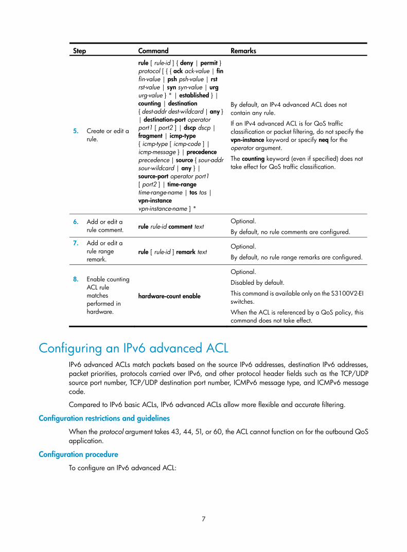
5. Create or edit a rule.
rule [ rule-id ] { deny | permit } protocol [ { { ack ack-value | fin fin-value | psh psh-value | rst rst-value | syn syn-value | urg urg-value } * | established } | counting | destination { dest-addr dest-wildcard | any } | destination-port operator port1 [ port2 ] | dscp dscp | fragment | icmp-type { icmp-type [ icmp-code ] | icmp-message } | precedence precedence | source { sour-addr sour-wildcard | any } | source-port operator port1 [ port2 ] | time-range time-range-name | tos tos | vpn-instance vpn-instance-name ] *
By default, an IPv4 advanced ACL does not contain any rule.
If an IPv4 advanced ACL is for QoS traffic classification or packet filtering, do not specify the vpn-instance keyword or specify neq for the operator argument.
The counting keyword (even if specified) does not take effect for QoS traffic classification.
6. Add or edit a rule comment. rule rule-id comment text
Optional.
By default, no rule comments are configured.
7. Add or edit a rule range remark.
rule [ rule-id ] remark text Optional.
By default, no rule range remarks are configured.
8. Enable counting ACL rule matches performed in hardware.
hardware-count enable
Optional.
Disabled by default.
This command is available only on the S3100V2-EI switches.
When the ACL is referenced by a QoS policy, this command does not take effect.
Configuring an IPv6 advanced ACL IPv6 advanced ACLs match packets based on the source IPv6 addresses, destination IPv6 addresses, packet priorities, protocols carried over IPv6, and other protocol header fields such as the TCP/UDP source port number, TCP/UDP destination port number, ICMPv6 message type, and ICMPv6 message code.
Compared to IPv6 basic ACLs, IPv6 advanced ACLs allow more flexible and accurate filtering.
Configuration restrictions and guidelines
When the protocol argument takes 43, 44, 51, or 60, the ACL cannot function on for the outbound QoS application.
Configuration procedure
To configure an IPv6 advanced ACL:

8
Step Command Remarks 1. Enter system
view. system-view N/A
2. Create an IPv6 advanced ACL and enter its view.
acl ipv6 number acl6-number [ name acl6-name ] [ match-order { auto | config } ]
By default, no ACL exists.
IPv6 advanced ACLs are numbered in the range of 3000 to 3999.
You can use the acl ipv6 name acl6-name command to enter the view of a named IPv6 ACL.
3. Configure a description for the IPv6 advanced ACL.
description text Optional.
By default, an IPv6 advanced ACL has no ACL description.
4. Set the rule numbering step.
step step-value Optional.
5 by default.
5. Create or edit a rule.
rule [ rule-id ] { deny | permit } protocol [ { { ack ack-value | fin fin-value | psh psh-value | rst rst-value | syn syn-value | urg urg-value } * | established } | counting | destination { dest dest-prefix | dest/dest-prefix | any } | destination-port operator port1 [ port2 ] | dscp dscp | flow-label flow-label-value | fragment | icmp6-type { icmp6-type icmp6-code | icmp6-message } | routing [ type routing-type ] | source { source source-prefix | source/source-prefix | any } | source-port operator port1 [ port2 ] | time-range time-range-name | vpn-instance vpn-instance-name ] *
By default IPv6 advanced ACL does not contain any rule.
If an IPv6 advanced ACL is for QoS traffic classification or packet filtering: • Do not specify the fragment and routing
keywords, or specify neq for the operator argument.
• Do not specify the flow-label keyword if the ACL is for outbound QoS traffic classification or outbound packet filtering.
The counting keyword (even if specified) does not take effect for QoS traffic classification.
6. Add or edit a rule comment. rule rule-id comment text
Optional.
By default, no rule comments are configured.
7. Add or edit a rule range remark.
rule [ rule-id ] remark text Optional.
By default, no rule range remarks are configured.
8. Enable counting ACL rule matches performed in hardware.
hardware-count enable
Optional.
Disabled by default.
When the ACL is referenced by a QoS policy, this command does not take effect.

9
Configuring an Ethernet frame header ACL Ethernet frame header ACLs, also called "Layer 2 ACLs," match packets based on Layer 2 protocol header fields, such as source MAC address, destination MAC address, 802.1p priority (VLAN priority), and link layer protocol type.
To configure an Ethernet frame header ACL:
Step Command Remarks 1. Enter system
view. system-view N/A
2. Create an Ethernet frame header ACL and enter its view.
acl number acl-number [ name acl-name ] [ match-order { auto | config } ]
By default, no ACL exists.
Ethernet frame header ACLs are numbered in the range of 4000 to 4999.
You can use the acl name acl-name command to enter the view of a named Ethernet frame header ACL.
3. Configure a description for the Ethernet frame header ACL.
description text Optional.
By default, an Ethernet frame header ACL has no ACL description.
4. Set the rule numbering step.
step step-value Optional.
The default setting is 5.
5. Create or edit a rule.
rule [ rule-id ] { deny | permit } [ cos vlan-pri | counting | dest-mac dest-addr dest-mask | { lsap lsap-type lsap-type-mask | type protocol-type protocol-type-mask } | source-mac sour-addr source-mask | time-range time-range-name ] *
By default, an Ethernet frame header ACL does not contain any rule.
The lsap keyword is not supported if the ACL is for QoS traffic classification.
6. Add or edit a rule comment. rule rule-id comment text
Optional.
By default, no rule comments are configured.
7. Add or edit a rule range remark.
rule [ rule-id ] remark text Optional.
By default, no rule range remarks are configured.
8. Enable counting ACL rule matches performed in hardware.
hardware-count enable
Optional.
Disabled by default.
When the ACL is referenced by a QoS policy, this command does not take effect.
Copying an ACL You can create an ACL by copying an existing ACL (source ACL). The new ACL (destination ACL) has the same properties and content as the source ACL, but not the same ACL number and name.

10
To successfully copy an ACL, make sure that:
• The destination ACL number is from the same category as the source ACL number.
• The source ACL already exists but the destination ACL does not.
Copying an IPv4 ACL
Step Command 1. Enter system view. system-view
2. Copy an existing IPv4 ACL to create a new IPv4 ACL.
acl copy { source-acl-number | name source-acl-name } to { dest-acl-number | name dest-acl-name }
Copying an IPv6 ACL
Step Command 1. Enter system view. system-view
2. Copy an existing IPv6 ACL to generate a new one of the same category.
acl ipv6 copy { source-acl6-number | name source-acl6-name } to { dest-acl6-number | name dest-acl6-name }
Packet filtering with ACLs You can use an ACL to filter incoming or outgoing IPv4 or IPv6 packets. You can apply one IPv4 ACL, one IPv6 AL, and one Ethernet frame header ACL most to filter packets in the same direction of an interface.
NOTE:
ACLs on VLAN interfaces filter only packets forwarded at Layer 3.
Applying an IPv4 or Ethernet frame header ACL for packet filtering
Step Command Remarks 1. Enter system view. system-view N/A
2. Enter interface view. interface interface-type interface-number N/A
3. Apply an IPv4 basic, IPv4 advanced, or Ethernet frame header ACL to the interface to filter packets.
packet-filter { acl-number | name acl-name } { inbound | outbound }
By default, no ACL is applied to any interface.
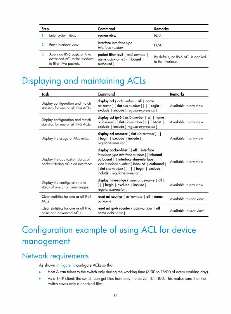
Applying an IPv6 ACL for packet filtering
11
Step Command Remarks 1. Enter system view. system-view N/A
2. Enter interface view. interface interface-type interface-number N/A
3. Apply an IPv6 basic or IPv6 advanced ACL to the interface to filter IPv6 packets.
packet-filter ipv6 { acl6-number | name acl6-name } { inbound | outbound }
By default, no IPv6 ACL is applied to the interface.
Displaying and maintaining ACLs
Task Command Remarks
Display configuration and match statistics for one or all IPv4 ACLs.
display acl { acl-number | all | name acl-name } [ slot slot-number ] [ | { begin | exclude | include } regular-expression ]
Available in any view
Display configuration and match statistics for one or all IPv6 ACLs.
display acl ipv6 { acl6-number | all | name acl6-name } [ slot slot-number ] [ | { begin | exclude | include } regular-expression ]
Available in any view
Display the usage of ACL rules. display acl resource [ slot slot-number ] [ | { begin | exclude | include } regular-expression ]
Available in any view
Display the application status of packet filtering ACLs on interfaces.
display packet-filter { { all | interface interface-type interface-number } [ inbound | outbound ] | interface vlan-interface vlan-interface-number [ inbound | outbound ] [ slot slot-number ] } [ | { begin | exclude | include } regular-expression ]
Available in any view
Display the configuration and status of one or all time ranges.
display time-range { time-range-name | all } [ | { begin | exclude | include } regular-expression ]
Available in any view
Clear statistics for one or all IPv4 ACLs.
reset acl counter { acl-number | all | name acl-name } Available in user view
Clear statistics for one or all IPv6 basic and advanced ACLs.
reset acl ipv6 counter { acl6-number | all | name acl6-name } Available in user view
Configuration example of using ACL for device management
Network requirements As shown in Figure 1, configure ACLs so that:
• Host A can telnet to the switch only during the working time (8:30 to 18:00 of every working day).
• As a TFTP client, the switch can get files from only the server 11.1.1.100. This makes sure that the switch saves only authorized files.

12
• As an FTP server, the switch accepts the login requests from only the NMS.
Figure 1 Network diagram
Configuration procedure 1. Limit the telnet login requests:
# Create a time range named telnet to cover 8:30 to 18:00 of every working day. <Switch> system-view
[Switch] time-range telnet 8:30 to 18:00 working-day
# Create IPv4 basic ACL 2000, and configure a rule for the ACL to permit the packets sourced from 10.1.3.1 during only the time specified by time range telnet. [Switch] acl number 2000
[Switch-acl-basic-2000] rule permit source 10.1.3.1 0 time-range telnet
[Switch-acl-basic-2000] quit
# Apply ACL 2000 to the inbound traffic of all telnet user interfaces to limit the telnet login requests. [Switch] user-interface vty 0 7
[Switch-ui-vty0-7] acl 2000 inbound
2. Limit the access to the TFTP server:
# Create IPv4 basic ACL 2001, and configure a rule for the ACL to permit only the packets sourced from 11.1.1.100. [Switch] acl number 2001
[Switch-acl-basic-2001] rule permit source 11.1.1.100 0
[Switch-acl-basic-2001] quit
# Use ACL 2001 to control the switch's access to a specific TFTP server. [Switch] tftp-server acl 2001
3. Limit the FTP login requests:
13
# Create IPv4 basic ACL 2002, and configure a rule for the ACL to permit only the packets sourced from 10.1.3.1. [Switch] acl number 2002
[Switch-acl-basic-2001] rule permit source 10.1.3.1 0
[Switch-acl-basic-2001] quit
# Enable the FTP server on the switch. [Switch] ftp server enable
# Use ACL 2001 to control FTP clients' access to the FTP server. [Switch] ftp server acl 2002
IPv4 packet filtering configuration example
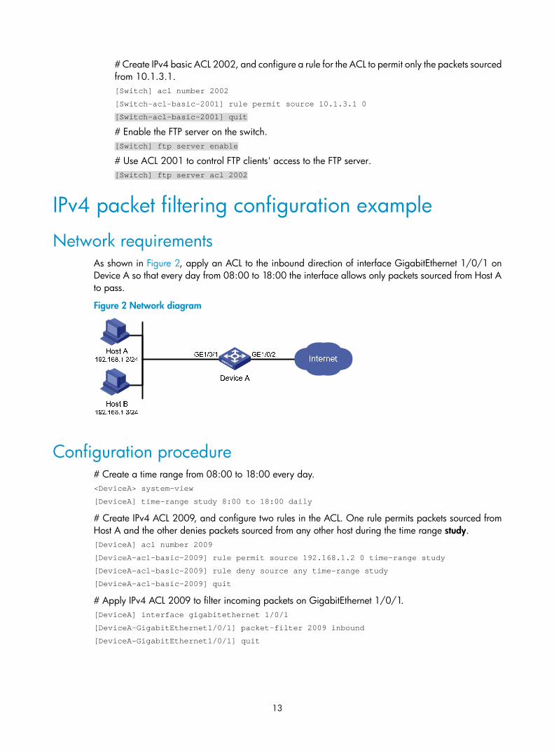
Network requirements As shown in Figure 2, apply an ACL to the inbound direction of interface GigabitEthernet 1/0/1 on Device A so that every day from 08:00 to 18:00 the interface allows only packets sourced from Host A to pass.
Figure 2 Network diagram
Configuration procedure # Create a time range from 08:00 to 18:00 every day. <DeviceA> system-view
[DeviceA] time-range study 8:00 to 18:00 daily
# Create IPv4 ACL 2009, and configure two rules in the ACL. One rule permits packets sourced from Host A and the other denies packets sourced from any other host during the time range study. [DeviceA] acl number 2009
[DeviceA-acl-basic-2009] rule permit source 192.168.1.2 0 time-range study
[DeviceA-acl-basic-2009] rule deny source any time-range study
[DeviceA-acl-basic-2009] quit
# Apply IPv4 ACL 2009 to filter incoming packets on GigabitEthernet 1/0/1. [DeviceA] interface gigabitethernet 1/0/1
[DeviceA-GigabitEthernet1/0/1] packet-filter 2009 inbound
[DeviceA-GigabitEthernet1/0/1] quit

14
IPv6 packet filtering configuration example
Network requirements As shown in Figure 3, apply an IPv6 ACL to the incoming traffic of GigabitEthernet 1/0/1 on Device A so that every day from 08:00 to 18:00 the interface allows only packets from Host A to pass through.
Figure 3 Network diagram
Configuration procedure # Create a time range from 08:00 to 18:00 every day. <DeviceA> system-view
[DeviceA] time-range study 8:0 to 18:0 daily
# Create IPv6 ACL 2009, and configure two rules for the ACL. One permits packets sourced from Host A and the other denies packets sourced from any other host during the time range study. [DeviceA] acl ipv6 number 2009
[DeviceA-acl6-basic-2009] rule permit source 1001::2 128 time-range study
[DeviceA-acl6-basic-2009] rule deny source any time-range study
[DeviceA-acl6-basic-2009] quit
# Apply IPv6 ACL 2009 to filter incoming packets on GigabitEthernet 1/0/1. [DeviceA] interface gigabitethernet 1/0/1
[DeviceA-GigabitEthernet1/0/1] packet-filter ipv6 2009 inbound
[DeviceA-GigabitEthernet1/0/1] quit

15
QoS overview
In data communications, Quality of Service (QoS) is a network’s ability to provide differentiated service guarantees for diversified traffic in terms of bandwidth, delay, jitter, and drop rate.
Network resources are scarce. The contention for resources requires that QoS prioritize important traffic flows over trivial ones. For example, in the case of fixed bandwidth, if a traffic flow gets more bandwidth, the other traffic flows will get less bandwidth and may be affected. When making a QoS scheme, you must consider the characteristics of various applications to balance the interests of diversified users and to utilize network resources.
The following section describes some typical QoS service models and widely used, mature QoS techniques.
QoS service models
Best-effort service model The best-effort model is a single-service model and also the simplest service model. In this service model, the network does its best to deliver packets, but does not guarantee delivery or control delay.
The best-effort service model is the default model in the Internet and applies to most network applications. It uses the first in first out (FIFO) queuing mechanism.
IntServ model The integrated service (IntServ) model is a multiple-service model that can accommodate diverse QoS requirements. This service model provides the most granularly differentiated QoS by identifying and guaranteeing definite QoS for each data flow.
In the IntServ model, an application must request service from the network before it sends data. IntServ signals the service request with the Resource Reservation Protocol (RSVP). All nodes receiving the request reserve resources as requested and maintain state information for the application flow.
The IntServ model demands high storage and processing capabilities because it requires all nodes along the transmission path to maintain resource state information for each flow. This model is suitable for small-sized or edge networks, but not large-sized networks, for example, the core layer of the Internet, where billions of flows are present.
DiffServ model The differentiated service (DiffServ) model is a multiple-service model that can satisfy diverse QoS requirements. It is easy to implement and extend. DiffServ does not signal the network to reserve resources before sending data, as IntServ does.
All QoS techniques in this document are based on the DiffServ model.

16
QoS techniques The QoS techniques include traffic classification, traffic policing, traffic shaping, line rate, congestion management, and congestion avoidance. They address problems that arise at different positions of a network.
Figure 4 Placement of the QoS techniques in a network
As shown in Figure 4, traffic classification, traffic shaping, traffic policing, congestion management, and congestion avoidance mainly implement the following functions:
• Traffic classification—Uses certain match criteria to assign packets with the same characteristics to a class. Based on classes, you can provide differentiated services.
• Traffic policing—Polices flows entering or leaving a device, and imposes penalties on traffic flows that exceed the pre-set threshold to prevent aggressive use of network resources. You can apply traffic policing to both incoming and outgoing traffic of a port.
• Traffic shaping—Proactively adapts the output rate of traffic to the network resources available on the downstream device to eliminate packet drops. Traffic shaping usually applies to the outgoing traffic of a port.
• Congestion management—Provides a resource scheduling policy to determine the packet forwarding sequence when congestion occurs. Congestion management usually applies to the outgoing traffic of a port.
• Congestion avoidance—Monitors the network resource usage, and is usually applied to the outgoing traffic of a port. When congestion worsens, congestion avoidance reduces the queue length by dropping packets.

17
QoS configuration approaches
You can configure QoS in these approaches:
• MQC approach
• Non-MQC approach
Some features support both approaches, but some support only one.
MQC approach In modular QoS configuration (MQC) approach, you configure QoS service parameters by using QoS policies (see "Configuring a QoS policy").
Non-MQC approach In non-MQC approach, you configure QoS service parameters without using a QoS policy. For example, you can use the line rate feature to set a rate limit on an interface without using a QoS policy.

18
Configuring a QoS policy
Overview A QoS policy is a set of class-behavior associations and defines the shaping, policing, or other QoS actions to take on different classes of traffic.
A class is a set of match criteria for identifying traffic and it uses the AND or OR operator:
• AND—A packet must match all the criteria to match the class.
• OR—A packet matches the class if it matches any of the criteria in the class.
A traffic behavior defines a set of QoS actions to take on packets, such as priority marking and redirect.
By associating a traffic behavior with a class in a QoS policy, you apply the specific set of QoS actions to the class of traffic.
Figure 5 shows how to configure a QoS policy.
Figure 5 QoS policy configuration procedure
Defining a class To define a class, specify its name and then configure the match criteria in class view.

19
Configuration restrictions and guidelines • If a class that uses the AND operator has multiple if-match acl, if-match acl ipv6, if-match
customer-vlan-id or if-match service-vlan-id clauses, a packet that matches any of the clauses matches the class.
• To successfully execute the traffic behavior associated with a traffic class that uses the AND operator, define only one if-match clause for any of the following match criteria and input only one value for any of the following list arguments. To create multiple if-match clauses for these match criteria or specify multiple values for the list arguments, specify the operator of the class as OR and use the if-match command multiple times.
customer-dot1p 8021p-list
destination-mac mac-address
dscp dscp-list
ip-precedence ip-precedence-list
service-dot1p 8021p-list
source-mac mac-address
Configuration procedure To define a class:
Step Command Remarks
1. Enter system view. system-view N/A
2. Create a class and enter class view.
traffic classifier tcl-name [ operator { and | or } ]
By default, the operator of a class is AND.
The operator of a class can be AND or OR: • AND—A packet is assigned to a class only when
the packet matches all the criteria in the class. • OR—A packet is assigned to a class if it matches
any of the criteria in the class. 3. Configure match
criteria. if-match match-criteria N/A
match-criteria: Match criterion.
Table 2 The value range for the match-criteria argument
Option Description
acl [ ipv6 ] { acl-number | name acl-name }
Matches an ACL.
The acl-number argument ranges from 2000 to 3999 for an IPv4 ACL, 2000 to 3999 for an IPv6 ACL, and 4000 to 4999 for an Ethernet frame header ACL.
The acl-name argument is a case-insensitive string of 1 to 63 characters, which must start with an alphabetic letter from a to z (or A to Z), and to avoid confusion, cannot be all.
any Matches all packets.
20
Option Description
dscp dscp-list Matches DSCP values.
The dscp-list argument is a list of up to eight DSCP values. A DSCP value can be a number from 0 to 63 or any keyword in Table 8.
destination-mac mac-address Matches a destination MAC address.
customer-dot1p 8021p-list Matches the 802.1p priority of the customer network.
The 8021p-list argument is a list of up to eight 802.1p priority values. An 802.1p priority ranges from 0 to 7.
service-dot1p 8021p-list Matches the 802.1p priority of the service provider network.
The 8021p-list argument is a list of up to eight 802.1p priority values. An 802.1p priority ranges from 0 to 7.
ip-precedence ip-precedence-list
Matches IP precedence.
The ip-precedence-list argument is a list of up to eight IP precedence values. An IP precedence ranges from 0 to 7.
protocol protocol-name Matches a protocol.
The protocol-name argument can be IP or IPv6.
qos-local-id local-id-value Matches a local QoS ID, which ranges from 1 to 4095.
The local QoS IDs supported on the HP 6125 switches are from 1 to 3999.
source-mac mac-address Matches a source MAC address.
customer-vlan-id { vlan-id-list | vlan-id1 to vlan-id2 }
Matches the VLAN IDs of customer networks.
The vlan-id-list argument is a list of up to eight VLAN IDs. The vlan-id1 to vlan-id2 specifies a VLAN ID range, where the vlan-id1 must be smaller than the vlan-id2. A VLAN ID ranges from 1 to 4094.
service-vlan-id { vlan-id-list | vlan-id1 to vlan-id2 }
Matches the VLAN IDs of ISP networks.
The vlan-id-list is a list of up to eight VLAN IDs. The vlan-id1 to vlan-id2 specifies a VLAN ID range, where the vlan-id1 must be smaller than the vlan-id2. A VLAN ID ranges from 1 to 4094.
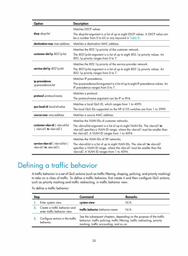
Defining a traffic behavior A traffic behavior is a set of QoS actions (such as traffic filtering, shaping, policing, and priority marking) to take on a class of traffic. To define a traffic behavior, first create it and then configure QoS actions, such as priority marking and traffic redirecting, in traffic behavior view.
To define a traffic behavior:
Step Command Remarks
1. Enter system view. system-view N/A
2. Create a traffic behavior and enter traffic behavior view. traffic behavior behavior-name N/A
3. Configure actions in the traffic behavior.
See the subsequent chapters, depending on the purpose of the traffic behavior: traffic policing, traffic filtering, traffic redirecting, priority marking, traffic accounting, and so on.
21
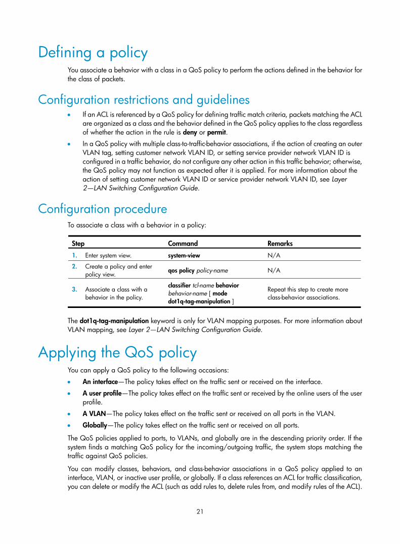
Defining a policy You associate a behavior with a class in a QoS policy to perform the actions defined in the behavior for the class of packets.
Configuration restrictions and guidelines • If an ACL is referenced by a QoS policy for defining traffic match criteria, packets matching the ACL
are organized as a class and the behavior defined in the QoS policy applies to the class regardless of whether the action in the rule is deny or permit.
• In a QoS policy with multiple class-to-traffic-behavior associations, if the action of creating an outer VLAN tag, setting customer network VLAN ID, or setting service provider network VLAN ID is configured in a traffic behavior, do not configure any other action in this traffic behavior; otherwise, the QoS policy may not function as expected after it is applied. For more information about the action of setting customer network VLAN ID or service provider network VLAN ID, see Layer 2—LAN Switching Configuration Guide.
Configuration procedure To associate a class with a behavior in a policy:
Step Command Remarks
1. Enter system view. system-view N/A
2. Create a policy and enter policy view. qos policy policy-name N/A
3. Associate a class with a behavior in the policy.
classifier tcl-name behavior behavior-name [ mode dot1q-tag-manipulation ]
Repeat this step to create more class-behavior associations.
The dot1q-tag-manipulation keyword is only for VLAN mapping purposes. For more information about VLAN mapping, see Layer 2—LAN Switching Configuration Guide.
Applying the QoS policy You can apply a QoS policy to the following occasions:
• An interface—The policy takes effect on the traffic sent or received on the interface.
• A user profile—The policy takes effect on the traffic sent or received by the online users of the user profile.
• A VLAN—The policy takes effect on the traffic sent or received on all ports in the VLAN.
• Globally—The policy takes effect on the traffic sent or received on all ports.
The QoS policies applied to ports, to VLANs, and globally are in the descending priority order. If the system finds a matching QoS policy for the incoming/outgoing traffic, the system stops matching the traffic against QoS policies.
You can modify classes, behaviors, and class-behavior associations in a QoS policy applied to an interface, VLAN, or inactive user profile, or globally. If a class references an ACL for traffic classification, you can delete or modify the ACL (such as add rules to, delete rules from, and modify rules of the ACL).
22
If a QoS policy has been applied to an active user profile, you cannot modify classes, behaviors, and class-behavior associations of the QoS policy, or delete the QoS policy.
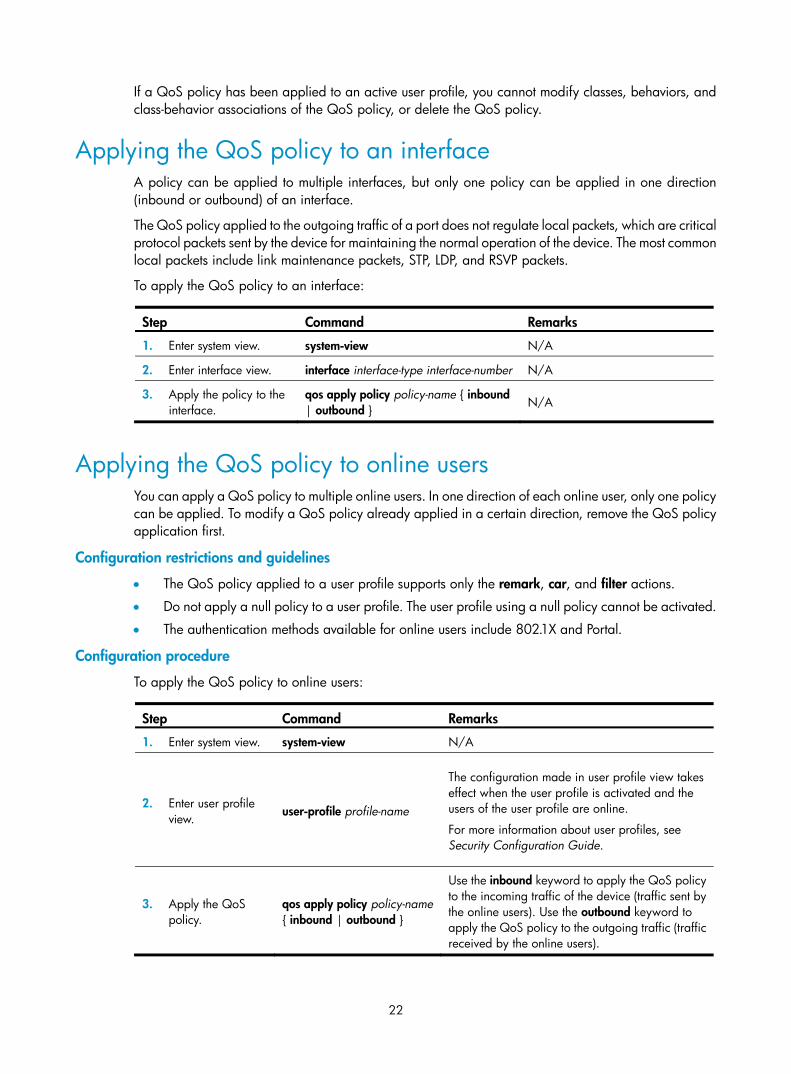
Applying the QoS policy to an interface A policy can be applied to multiple interfaces, but only one policy can be applied in one direction (inbound or outbound) of an interface.
The QoS policy applied to the outgoing traffic of a port does not regulate local packets, which are critical protocol packets sent by the device for maintaining the normal operation of the device. The most common local packets include link maintenance packets, STP, LDP, and RSVP packets.
To apply the QoS policy to an interface:
Step Command Remarks
1. Enter system view. system-view N/A
2. Enter interface view. interface interface-type interface-number N/A
3. Apply the policy to the interface.
qos apply policy policy-name { inbound | outbound } N/A
Applying the QoS policy to online users You can apply a QoS policy to multiple online users. In one direction of each online user, only one policy can be applied. To modify a QoS policy already applied in a certain direction, remove the QoS policy application first.
Configuration restrictions and guidelines
• The QoS policy applied to a user profile supports only the remark, car, and filter actions.
• Do not apply a null policy to a user profile. The user profile using a null policy cannot be activated.
• The authentication methods available for online users include 802.1X and Portal.
Configuration procedure
To apply the QoS policy to online users:
Step Command Remarks
1. Enter system view. system-view N/A
2. Enter user profile view. user-profile profile-name
The configuration made in user profile view takes effect when the user profile is activated and the users of the user profile are online.
For more information about user profiles, see Security Configuration Guide.
3. Apply the QoS policy.
qos apply policy policy-name { inbound | outbound }
Use the inbound keyword to apply the QoS policy to the incoming traffic of the device (traffic sent by the online users). Use the outbound keyword to apply the QoS policy to the outgoing traffic (traffic received by the online users).

23
Step Command Remarks 4. Return to system
view. quit N/A
5. Activate the user profile.
user-profile profile-name enable
By default, a user profile is inactive.
Applying the QoS policy to a VLAN You can apply a QoS policy to a VLAN to regulate traffic of the VLAN.
QoS policies cannot be applied to dynamic VLANs, such as VLANs created by GVRP.
To apply the QoS policy to a VLAN:
Step Command Remarks
1. Enter system view. system-view N/A
2. Apply the QoS policy to VLANs.
qos vlan-policy policy-name vlan vlan-id-list { inbound | outbound } N/A
Applying the QoS policy globally You can apply a QoS policy globally to the inbound or outbound direction of all ports.
To apply the QoS policy globally:
Step Command Remarks
1. Enter system view. system-view N/A
2. Apply the QoS policy globally.
qos apply policy policy-name global { inbound | outbound } N/A
Displaying and maintaining QoS policies
Task Command Remarks
Display traffic class configuration. display traffic classifier user-defined [ tcl-name ] [ | { begin | exclude | include } regular-expression ]
Available in any view
Display traffic behavior configuration.
display traffic behavior user-defined [ behavior-name ] [ | { begin | exclude | include } regular-expression ]
Available in any view
Display user-defined QoS policy configuration.
display qos policy user-defined [ policy-name [ classifier tcl-name ] ] [ | { begin | exclude | include } regular-expression ]
Available in any view
Display QoS policy configuration on the specified or all interfaces.
display qos policy interface [ interface-type interface-number ] [ inbound | outbound ] [ | { begin | exclude | include } regular-expression ]
Available in any view
24
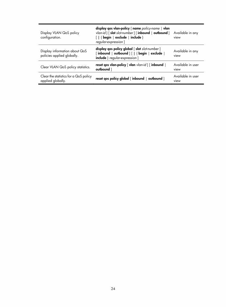
Display VLAN QoS policy configuration.
display qos vlan-policy { name policy-name | vlan vlan-id } [ slot slot-number ] [ inbound | outbound ] [ | { begin | exclude | include } regular-expression ]
Available in any view
Display information about QoS policies applied globally.
display qos policy global [ slot slot-number ] [ inbound | outbound ] [ | { begin | exclude | include } regular-expression ]
Available in any view
Clear VLAN QoS policy statistics. reset qos vlan-policy [ vlan vlan-id ] [ inbound | outbound ]
Available in user view
Clear the statistics for a QoS policy applied globally. reset qos policy global [ inbound | outbound ]
Available in user view
25
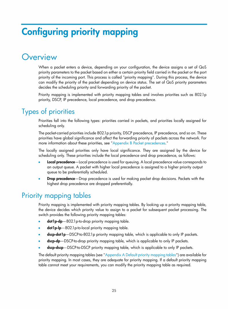
Configuring priority mapping
Overview When a packet enters a device, depending on your configuration, the device assigns a set of QoS priority parameters to the packet based on either a certain priority field carried in the packet or the port priority of the incoming port. This process is called "priority mapping". During this process, the device can modify the priority of the packet depending on device status. The set of QoS priority parameters decides the scheduling priority and forwarding priority of the packet.
Priority mapping is implemented with priority mapping tables and involves priorities such as 802.1p priority, DSCP, IP precedence, local precedence, and drop precedence.
Types of priorities Priorities fall into the following types: priorities carried in packets, and priorities locally assigned for scheduling only.
The packet-carried priorities include 802.1p priority, DSCP precedence, IP precedence, and so on. These priorities have global significance and affect the forwarding priority of packets across the network. For more information about these priorities, see "Appendix B Packet precedences."
The locally assigned priorities only have local significance. They are assigned by the device for scheduling only. These priorities include the local precedence and drop precedence, as follows:
• Local precedence—Local precedence is used for queuing. A local precedence value corresponds to an output queue. A packet with higher local precedence is assigned to a higher priority output queue to be preferentially scheduled.
• Drop precedence—Drop precedence is used for making packet drop decisions. Packets with the highest drop precedence are dropped preferentially.
Priority mapping tables Priority mapping is implemented with priority mapping tables. By looking up a priority mapping table, the device decides which priority value to assign to a packet for subsequent packet processing. The switch provides the following priority mapping tables:
• dot1p-dp—802.1p-to-drop priority mapping table.
• dot1p-lp—802.1p-to-local priority mapping table.
• dscp-dot1p—DSCP-to-802.1p priority mapping table, which is applicable to only IP packets.
• dscp-dp—DSCP-to-drop priority mapping table, which is applicable to only IP packets.
• dscp-dscp—DSCP-to-DSCP priority mapping table, which is applicable to only IP packets.
The default priority mapping tables (see "Appendix A Default priority mapping tables") are available for priority mapping. In most cases, they are adequate for priority mapping. If a default priority mapping table cannot meet your requirements, you can modify the priority mapping table as required.

26
Priority trust mode on a port The priority trust mode on a port decides which priority is used for priority mapping table lookup. Port priority was introduced to use for priority mapping in addition to priority fields carried in packets. The HP Blade 6125 Switch Series provides the following priority trust modes:
• Using the 802.1p priority carried in packets for priority mapping.
• Using the DSCP carried in packets for priority mapping.
The priority mapping procedure varies with the priority modes. For more information, see the subsequent section.
Priority mapping procedure On receiving an Ethernet packet on a port, the switch marks the scheduling priorities (local precedence and drop precedence) for the Ethernet packet. This procedure is done according to the priority trust mode of the receiving port and the 802.1q tagging status of the packet, as shown in Figure 6.
Figure 6 Priority mapping procedure for an Ethernet packet
The priority mapping procedure shown in Figure 6 applies in the absence of priority marking. If priority marking is configured, the switch performs priority marking before priority mapping. The switch then uses the re-marked packet-carried priority for priority mapping or directly uses the re-marked scheduling
Which priority is trusted on the
port?
Receive a packet on a port
Use the port priority as the
802.1p priority of the packet
Look up the dot1p-dp and
dot1p-lp tables
Mark the packet with local
precedence and drop precedence
Is the packet 802.1q tagged?
DSCP in packets
Look up the dscp-dp, dscp-
dot1p, and dscp-dscp tables
802.1p in packets
Mark the packet with 802.1ppriority, drop
precedence, and new DSCPprecedence
Look up the dot1p-lp table
Mark the packet with local
precedence
Look up the dot1p-dp and
dot1p-lp tables
Mark the packet with local
precedence and drop precedence
Schedule the packet according to its local precedence and drop
precedence
Y
N

27
priority for traffic scheduling depending on your configuration. Neither priority trust mode configuration on the port nor port priority configuration takes effect.
Configuration guidelines You can modify priority mappings by modifying priority mapping tables, priority trust mode on a port, and port priority.
HP recommends planning QoS throughout the network before making your QoS configuration.
Configuring a priority mapping table
Step Command Remarks 1. Enter system
view. system-view N/A
2. Enter priority mapping table view.
qos map-table { dot1p-dp | dot1p-lp | dscp-dot1p | dscp-dp | dscp-dscp }
N/A
3. Configure the priority mapping table.
import import-value-list export export-value Newly configured mappings overwrite the old ones.
Configuring a port to trust packet priority for priority mapping
When you configure the trusted packet priority type on an interface, use the following priority trust modes:
• dot1p—Uses the 802.1p priority of received packets for mapping.
• dscp—Uses the DSCP precedence of received IP packets for mapping.
To configure the trusted packet priority type on an interface:
Step Command Remarks
1. Enter system view system-view N/A
2. Enter interface view. interface interface-type interface-number N/A
3. Configure the trusted packet priority type for the interface.
• Trust the DSCP priority in packets: qos trust dscp
• Trust the 802.1p priority in packets: qos trust dot1p
Use either command.
By default, the device trusts the 802.1p priority in packets.
Changing the port priority of an interface To change the port priority of an interface:
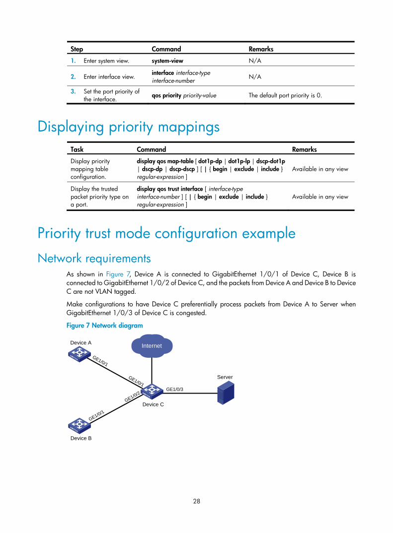
28
Step Command Remarks
1. Enter system view. system-view N/A
2. Enter interface view. interface interface-type interface-number N/A
3. Set the port priority of the interface.
qos priority priority-value The default port priority is 0.
Displaying priority mappings
Task Command Remarks
Display priority mapping table configuration.
display qos map-table [ dot1p-dp | dot1p-lp | dscp-dot1p | dscp-dp | dscp-dscp ] [ | { begin | exclude | include } regular-expression ]
Available in any view
Display the trusted packet priority type on a port.
display qos trust interface [ interface-type interface-number ] [ | { begin | exclude | include } regular-expression ]
Available in any view
Priority trust mode configuration example
Network requirements As shown in Figure 7, Device A is connected to GigabitEthernet 1/0/1 of Device C, Device B is connected to GigabitEthernet 1/0/2 of Device C, and the packets from Device A and Device B to Device C are not VLAN tagged.
Make configurations to have Device C preferentially process packets from Device A to Server when GigabitEthernet 1/0/3 of Device C is congested.
Figure 7 Network diagram
InternetDevice A
Device C
Server
GE1/0/1
GE1/0/1
Device B
GE1/0/3
GE1/0/1
GE1/0/2
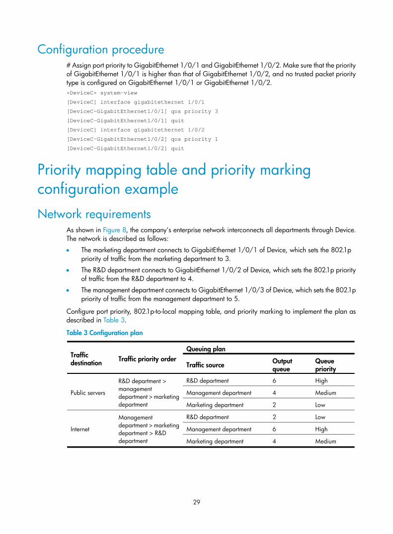
29
Configuration procedure # Assign port priority to GigabitEthernet 1/0/1 and GigabitEthernet 1/0/2. Make sure that the priority of GigabitEthernet 1/0/1 is higher than that of GigabitEthernet 1/0/2, and no trusted packet priority type is configured on GigabitEthernet 1/0/1 or GigabitEthernet 1/0/2. <DeviceC> system-view
[DeviceC] interface gigabitethernet 1/0/1
[DeviceC-GigabitEthernet1/0/1] qos priority 3
[DeviceC-GigabitEthernet1/0/1] quit
[DeviceC] interface gigabitethernet 1/0/2
[DeviceC-GigabitEthernet1/0/2] qos priority 1
[DeviceC-GigabitEthernet1/0/2] quit
Priority mapping table and priority marking configuration example
Network requirements As shown in Figure 8, the company's enterprise network interconnects all departments through Device. The network is described as follows:
• The marketing department connects to GigabitEthernet 1/0/1 of Device, which sets the 802.1p priority of traffic from the marketing department to 3.
• The R&D department connects to GigabitEthernet 1/0/2 of Device, which sets the 802.1p priority of traffic from the R&D department to 4.
• The management department connects to GigabitEthernet 1/0/3 of Device, which sets the 802.1p priority of traffic from the management department to 5.
Configure port priority, 802.1p-to-local mapping table, and priority marking to implement the plan as described in Table 3.
Table 3 Configuration plan
Traffic destination Traffic priority order
Queuing plan
Traffic source Output queue
Queue priority
Public servers
R&D department > management department > marketing department
R&D department 6 High
Management department 4 Medium
Marketing department 2 Low
Internet
Management department > marketing department > R&D department
R&D department 2 Low
Management department 6 High
Marketing department 4 Medium

30
Figure 8 Network diagram
Configuration procedure 1. Configure trusting port priority:
# Set the port priority of GigabitEthernet 1/0/1 to 3. <Device> system-view
[Device] interface gigabitethernet 1/0/1
[Device-GigabitEthernet1/0/1] qos priority 3
[Device-GigabitEthernet1/0/1] quit
# Set the port priority of GigabitEthernet 1/0/2 to 4. [Device] interface gigabitethernet 1/0/2
[Device-GigabitEthernet1/0/2] qos priority 4
[Device-GigabitEthernet1/0/2] quit
# Set the port priority of GigabitEthernet 1/0/3 to 5. [Device] interface gigabitethernet 1/0/3
[Device-GigabitEthernet1/0/3] qos priority 5
[Device-GigabitEthernet1/0/3] quit
2. Configure the 802.1p-to-local mapping table to map 802.1p priority values 3, 4, and 5 to local precedence values 2, 6, and 4.
This guarantees the R&D department, management department, and marketing department decreased priorities to access the public server. [Device] qos map-table dot1p-lp
[Device-maptbl-dot1p-lp] import 3 export 2
[Device-maptbl-dot1p-lp] import 4 export 6
Host
Server
R&D department
Internet
Device
GE1/0/3
Marketing department
Host
Server
Host
Server
Management department
Public servers
GE1/0/4
GE1/0/5
GE1/0/2
GE1/0/1

31
[Device-maptbl-dot1p-lp] import 5 export 4
[Device-maptbl-dot1p-lp] quit
3. Configure priority marking:
# Mark the HTTP traffic of the management department, marketing department, and R&D department to the Internet with 802.1p priorities 4, 5, and 3, respectively. Use the priority mapping table you have configured to map the 802.1p priorities to local precedence values 6, 4, and 2, respectively, for differentiated traffic treatment.
# Create ACL 3000 to match HTTP traffic. [Device] acl number 3000
[Device-acl-adv-3000] rule permit tcp destination-port eq 80
[Device-acl-adv-3000] quit
# Create class http and reference ACL 3000 in the class. [Device] traffic classifier http
[Device-classifier-http] if-match acl 3000
[Device-classifier-http] quit
# Configure a priority marking policy for the management department, and apply the policy to the incoming traffic of GigabitEthernet 1/0/3. [Device] traffic behavior admin
[Device-behavior-admin] remark dot1p 4
[Device-behavior-admin] quit
[Device] qos policy admin
[Device-qospolicy-admin] classifier http behavior admin
[Device-qospolicy-admin] quit
[Device] interface gigabitethernet 1/0/3
[Device-GigabitEthernet1/0/3] qos apply policy admin inbound
# Configure a priority marking policy for the marketing department, and apply the policy to the incoming traffic of GigabitEthernet 1/0/1. [Device] traffic behavior market
[Device-behavior-market] remark dot1p 5
[Device-behavior-market] quit
[Device] qos policy market
[Device-qospolicy-market] classifier http behavior market
[Device-qospolicy-market] quit
[Device] interface gigabitethernet 1/0/1
[Device-GigabitEthernet1/0/1] qos apply policy market inbound
# Configure a priority marking policy for the R&D department, and apply the policy to the incoming traffic of GigabitEthernet 1/0/2. [Device] traffic behavior rd
[Device-behavior-rd] remark dot1p 3
[Device-behavior-rd] quit
[Device] qos policy rd
[Device-qospolicy-rd] classifier http behavior rd
[Device-qospolicy-rd] quit
[Device] interface gigabitethernet 1/0/2
[Device-GigabitEthernet1/0/2] qos apply policy rd inbound

32
Configuring traffic policing, traffic shaping, and line rate
Overview Traffic policing, traffic shaping, and rate limit are QoS technologies that help assign network resources, such as assign bandwidth. They increase network performance and user satisfaction. For example, you can configure a flow to use only the resources committed to it in a certain time range. This avoids network congestion caused by burst traffic.
Traffic policing, generic traffic shaping (GTS), and line rate limit the traffic rate and resource usage according to traffic specifications. Once a particular flow exceeds its specifications, such as assigned bandwidth, the flow is shaped or policed to make sure that it is under the specifications. You can use token buckets for evaluating traffic specifications.
Traffic evaluation and token buckets A token bucket is analogous to a container that holds a certain number of tokens. Each token represents a certain forwarding capacity. The system puts tokens into the bucket at a constant rate. When the token bucket is full, the extra tokens cause the token bucket to overflow.
Evaluating traffic with the token bucket
A token bucket mechanism evaluates traffic by looking at the number of tokens in the bucket. If the number of tokens in the bucket is enough for forwarding the packets, the traffic conforms to the specification, and is called "conforming traffic". Otherwise, the traffic does not conform to the specification, and is called "excess traffic".
A token bucket has the following configurable parameters:
• Mean rate at which tokens are put into the bucket, which is the permitted average rate of traffic. It is usually set to the committed information rate (CIR).
• Burst size or the capacity of the token bucket. It is the maximum traffic size permitted in each burst. It is usually set to the committed burst size (CBS). The set burst size must be greater than the maximum packet size.
Each arriving packet is evaluated. In each evaluation, if the number of tokens in the bucket is enough, the traffic conforms to the specification and the tokens for forwarding the packet are taken away; if the number of tokens in the bucket is not enough, the traffic is excessive.
Complicated evaluation
You can set two token buckets, bucket C and bucket E, to evaluate traffic in a more complicated environment and achieve more policing flexibility. For example, traffic policing uses the following parameters:
• CIR—Rate at which tokens are put into bucket C. It sets the average packet transmission or forwarding rate allowed by bucket C.
• CBS—Size of bucket C, which specifies the transient burst of traffic that bucket C can forward.
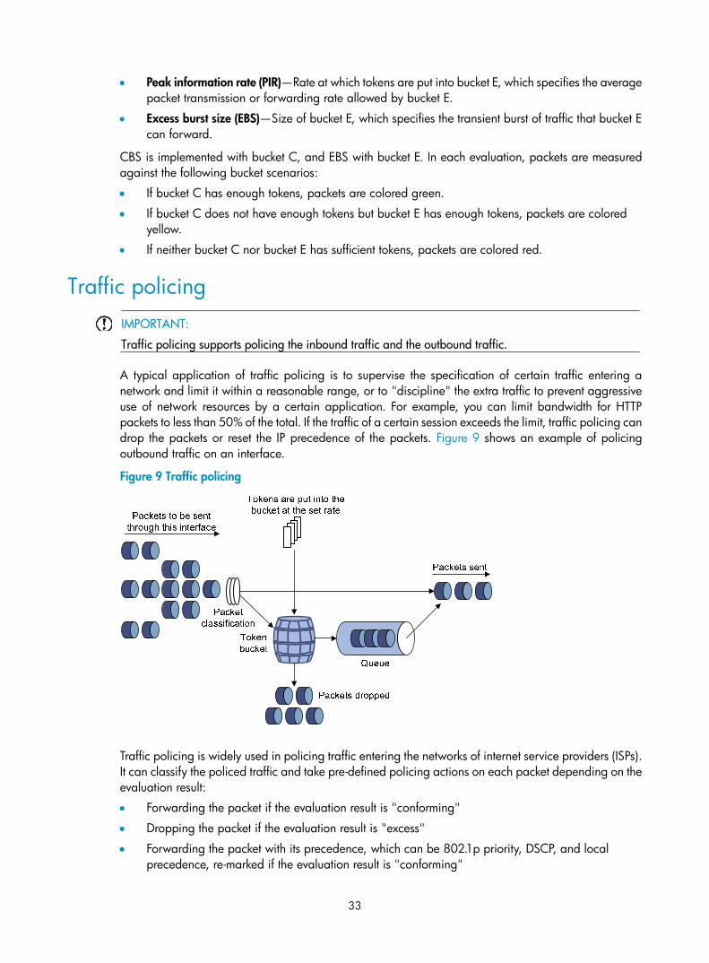
33
• Peak information rate (PIR)—Rate at which tokens are put into bucket E, which specifies the average packet transmission or forwarding rate allowed by bucket E.
• Excess burst size (EBS)—Size of bucket E, which specifies the transient burst of traffic that bucket E can forward.
CBS is implemented with bucket C, and EBS with bucket E. In each evaluation, packets are measured against the following bucket scenarios:
• If bucket C has enough tokens, packets are colored green.
• If bucket C does not have enough tokens but bucket E has enough tokens, packets are colored yellow.
• If neither bucket C nor bucket E has sufficient tokens, packets are colored red.
Traffic policing
IMPORTANT:
Traffic policing supports policing the inbound traffic and the outbound traffic.
A typical application of traffic policing is to supervise the specification of certain traffic entering a network and limit it within a reasonable range, or to "discipline" the extra traffic to prevent aggressive use of network resources by a certain application. For example, you can limit bandwidth for HTTP packets to less than 50% of the total. If the traffic of a certain session exceeds the limit, traffic policing can drop the packets or reset the IP precedence of the packets. Figure 9 shows an example of policing outbound traffic on an interface.
Figure 9 Traffic policing
Traffic policing is widely used in policing traffic entering the networks of internet service providers (ISPs). It can classify the policed traffic and take pre-defined policing actions on each packet depending on the evaluation result:
• Forwarding the packet if the evaluation result is "conforming"
• Dropping the packet if the evaluation result is "excess"
• Forwarding the packet with its precedence, which can be 802.1p priority, DSCP, and local precedence, re-marked if the evaluation result is "conforming"

34
Traffic shaping
IMPORTANT:
Traffic shaping shapes the outbound traffic.
Traffic shaping limits the outbound traffic rate by buffering exceeding traffic. You can use traffic shaping to adapt the traffic output rate on a device to the input traffic rate of its connected device to avoid packet loss.
The difference between traffic policing and GTS is that packets to be dropped with traffic policing are retained in a buffer or queue with GTS, as shown in Figure 10. When enough tokens are in the token bucket, the buffered packets are sent at an even rate. Traffic shaping can result in additional delay and traffic policing does not.
Figure 10 GTS
For example, in Figure 11, Device B performs traffic policing on packets from Device A and drops packets exceeding the limit. To avoid packet loss, you can perform traffic shaping on the outgoing interface of Device A so packets exceeding the limit are cached in Device A. Once resources are released, traffic shaping takes out the cached packets and sends them out.
Figure 11 GTS application
Line rate Line rate supports rate-limiting the inbound traffic and the outbound traffic.
Device A Device B
Physical link

35
The line rate of a physical interface specifies the maximum rate for forwarding packets (including critical packets).
Line rate also uses token buckets for traffic control. With line rate configured on an interface, all packets to be sent through the interface are handled by the token bucket at line rate. If enough tokens are in the token bucket, packets can be forwarded. Otherwise, packets are put into QoS queues for congestion management. In this way, the traffic passing the physical interface is controlled.
Figure 12 Line rate implementation
The token bucket mechanism limits traffic rate when accommodating bursts. It allows bursty traffic to be transmitted if enough tokens are available. If tokens are scarce, packets cannot be transmitted until efficient tokens are generated in the token bucket. It restricts the traffic rate to the rate for generating tokens.
Line rate can only limit traffic rate on a physical interface, and traffic policing can limit the rate of a flow on an interface. To limit the rate of all the packets on interfaces, using line rate is easier.
Configuring traffic policing
Configuration restrictions and guidelines In a traffic behavior, do not configure traffic policing with any priority marking action (including local precedence, drop precedence, 802.1p priority, DSCP value, and IP precedence marking actions) in the same traffic behavior. Otherwise, you will fail to apply the QoS policy successfully.
Configuration procedure To configure traffic policing:
Step Command Remarks
1. Enter system view. system-view N/A
2. Create a class and enter class view.
traffic classifier tcl-name [ operator { and | or } ] N/A
3. Configure match criteria. if-match match-criteria N/A

36
Step Command Remarks
4. Return to system view. quit N/A
5. Create a behavior and enter behavior view.
traffic behavior behavior-name N/A
6. Configure a traffic policing action.
car cir committed-information-rate [ cbs committed-burst-size [ ebs excess-burst-size ] ] [ pir peak-information-rate ] [ green action ] [ yellow action ] [ red action ]
N/A.
7. Return to system view. quit N/A
8. Create a policy and enter policy view. qos policy policy-name N/A
9. Associate the class with the traffic behavior in the QoS policy.
classifier tcl-name behavior behavior-name N/A
10. Return to system view. quit N/A
11. Apply the QoS policy.
• Applying the QoS policy to an interface
• Applying the QoS policy to online users
• Applying the QoS policy to a VLAN • Applying the QoS policy globally
Choose one application destination as needed.
Configuring GTS The Switch Series supports queue-based GTS, which shapes traffic of a specific queue.
To configure GTS:
Step Command Remarks
1. Enter system view. system-view N/A
2. Enter interface view. interface interface-type interface-number N/A
3. Configure GTS for a queue. qos gts queue queue-number cir committed-information-rate [ cbs committed-burst-size ]
N/A
Configuring the line rate The line rate of a physical interface specifies the maximum rate of incoming packets or outgoing packets.
To configure the line rate:
Step Command Remarks
1. Enter system view. system-view N/A

37
2. Enter interface view. interface interface-type interface-number N/A
3. Configure the line rate for the interface.
qos lr { inbound | outbound } cir committed-information-rate [ cbs committed-burst-size ]
N/A
Displaying and maintaining traffic policing, GTS, and line rate
On the HP Blade 6125 Switch Series, you can configure traffic policing in MQC approach. For more information about the displaying and maintaining commands, see "Displaying and maintaining QoS policies."
Task Command Remarks
Display interface GTS configuration information.
display qos gts interface [ interface-type interface-number ] [ | { begin | exclude | include } regular-expression ]
Available in any view
Display interface line rate configuration information.
display qos lr interface [ interface-type interface-number ] [ | { begin | exclude | include } regular-expression ]
Available in any view
Traffic policing configuration example
Network requirements As shown in Figure 13:
• GigabitEthernet 1/0/3 of Device A is connected to GigabitEthernet1/0/1 of Device B.
• Server, Host A, and Host B can access the Internet through Device A and Device B.
Perform traffic control on GigabitEthernet 1/0/1 of Device A for traffic received from Server and Host A, respectively, to satisfy the following requirements:
• Limit the rate of traffic from Server to 1024 kbps: transmit the conforming traffic normally, and mark the excess traffic with DSCP value 0 and then transmit the traffic.
• Limit the rate of traffic from Host A to 256 kbps: transmit the conforming traffic normally, and drop the excess traffic.
Perform traffic control on GigabitEthernet 1/0/1 and GigabitEthernet 1/0/2 of Device B to satisfy the following requirements:
• Limit the total incoming traffic rate of GigabitEthernet 1/0/1 to 2048 kbps, and drop the excess traffic.
• Limit the outgoing HTTP traffic (traffic accessing the Internet) rate of GigabitEthernet 1/0/2 to 1024 kbps, and drop the excess traffic.

38
Figure 13 Network diagram
Configuration procedures 1. Configure Device A:
# Configure ACL 2001 and ACL 2002 to match traffic from Server and Host A, respectively. <DeviceA> system-view
[DeviceA] acl number 2001
[DeviceA-acl-basic-2001] rule permit source 1.1.1.1 0
[DeviceA-acl-basic-2001] quit
[DeviceA] acl number 2002
[DeviceA-acl-basic-2002] rule permit source 1.1.1.2 0
[DeviceA-acl-basic-2002] quit
# Create a class named server, and use ACL 2001 as the match criterion. Create a class named host, and use ACL 2002 as the match criterion. [DeviceA] traffic classifier server
[DeviceA-classifier-server] if-match acl 2001
[DeviceA-classifier-server] quit
[DeviceA] traffic classifier host
[DeviceA-classifier-host] if-match acl 2002
[DeviceA-classifier-host] quit
# Create a behavior named server, and configure the CAR action for the behavior as follows: set the CIR to 1024 kbps, and mark the excess packets (red packets) with DSCP value 0 and transmit them. [DeviceA] traffic behavior server
[DeviceA-behavior-server] car cir 1024 red remark-dscp-pass 0
[DeviceA-behavior-server] quit
# Create a behavior named host, and configure the CAR action for the behavior as follows: set the CIR to 256 kbps. [DeviceA] traffic behavior host
[DeviceA-behavior-host] car cir 256
[DeviceA-behavior-host] quit
# Create a QoS policy named car, and associate class server with behavior server and class host with behavior host. [DeviceA] qos policy car
[DeviceA-qospolicy-car] classifier server behavior server
[DeviceA-qospolicy-car] classifier host behavior host
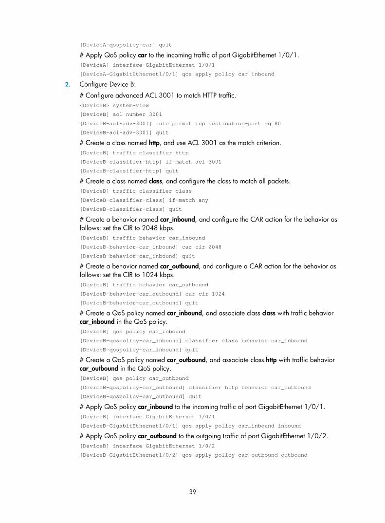
39
[DeviceA-qospolicy-car] quit
# Apply QoS policy car to the incoming traffic of port GigabitEthernet 1/0/1. [DeviceA] interface GigabitEthernet 1/0/1
[DeviceA-GigabitEthernet1/0/1] qos apply policy car inbound
2. Configure Device B:
# Configure advanced ACL 3001 to match HTTP traffic. <DeviceB> system-view
[DeviceB] acl number 3001
[DeviceB-acl-adv-3001] rule permit tcp destination-port eq 80
[DeviceB-acl-adv-3001] quit
# Create a class named http, and use ACL 3001 as the match criterion. [DeviceB] traffic classifier http
[DeviceB-classifier-http] if-match acl 3001
[DeviceB-classifier-http] quit
# Create a class named class, and configure the class to match all packets. [DeviceB] traffic classifier class
[DeviceB-classifier-class] if-match any
[DeviceB-classifier-class] quit
# Create a behavior named car_inbound, and configure the CAR action for the behavior as follows: set the CIR to 2048 kbps. [DeviceB] traffic behavior car_inbound
[DeviceB-behavior-car_inbound] car cir 2048
[DeviceB-behavior-car_inbound] quit
# Create a behavior named car_outbound, and configure a CAR action for the behavior as follows: set the CIR to 1024 kbps. [DeviceB] traffic behavior car_outbound
[DeviceB-behavior-car_outbound] car cir 1024
[DeviceB-behavior-car_outbound] quit
# Create a QoS policy named car_inbound, and associate class class with traffic behavior car_inbound in the QoS policy. [DeviceB] qos policy car_inbound
[DeviceB-qospolicy-car_inbound] classifier class behavior car_inbound
[DeviceB-qospolicy-car_inbound] quit
# Create a QoS policy named car_outbound, and associate class http with traffic behavior car_outbound in the QoS policy. [DeviceB] qos policy car_outbound
[DeviceB-qospolicy-car_outbound] classifier http behavior car_outbound
[DeviceB-qospolicy-car_outbound] quit
# Apply QoS policy car_inbound to the incoming traffic of port GigabitEthernet 1/0/1. [DeviceB] interface GigabitEthernet 1/0/1
[DeviceB-GigabitEthernet1/0/1] qos apply policy car_inbound inbound
# Apply QoS policy car_outbound to the outgoing traffic of port GigabitEthernet 1/0/2. [DeviceB] interface GigabitEthernet 1/0/2
[DeviceB-GigabitEthernet1/0/2] qos apply policy car_outbound outbound
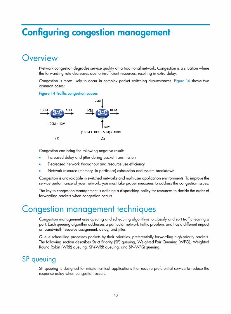
40
Configuring congestion management
Overview Network congestion degrades service quality on a traditional network. Congestion is a situation where the forwarding rate decreases due to insufficient resources, resulting in extra delay.
Congestion is more likely to occur in complex packet switching circumstances. Figure 14 shows two common cases:
Figure 14 Traffic congestion causes
Congestion can bring the following negative results:
• Increased delay and jitter during packet transmission
• Decreased network throughput and resource use efficiency
• Network resource (memory, in particular) exhaustion and system breakdown
Congestion is unavoidable in switched networks and multi-user application environments. To improve the service performance of your network, you must take proper measures to address the congestion issues.
The key to congestion management is defining a dispatching policy for resources to decide the order of forwarding packets when congestion occurs.
Congestion management techniques Congestion management uses queuing and scheduling algorithms to classify and sort traffic leaving a port. Each queuing algorithm addresses a particular network traffic problem, and has a different impact on bandwidth resource assignment, delay, and jitter.
Queue scheduling processes packets by their priorities, preferentially forwarding high-priority packets. The following section describes Strict Priority (SP) queuing, Weighted Fair Queuing (WFQ), Weighted Round Robin (WRR) queuing, SP+WRR queuing, and SP+WFQ queuing.
SP queuing SP queuing is designed for mission-critical applications that require preferential service to reduce the response delay when congestion occurs.

41
Figure 15 SP queuing
In Figure 15, SP queuing classifies eight queues on a port into eight classes, numbered 7 to 0 in descending priority order.
SP queuing schedules the eight queues in the descending order of priority. SP queuing sends packets in the queue with the highest priority first. When the queue with the highest priority is empty, it sends packets in the queue with the second highest priority, and so on. You can assign mission-critical packets to the high priority queue to make sure that they are always served first, and assign common service packets to the low priority queues and transmitted when the high priority queues are empty.
The disadvantage of SP queuing is that packets in the lower priority queues cannot be transmitted if packets exist in the higher priority queues. This may cause lower priority traffic to starve to death.
WRR queuing WRR queuing schedules all the queues in turn to ensure every queue is served for a certain time, as shown in Figure 16.
Figure 16 WRR queuing
Queue 7
Queue 6
Queue 1
Queue 0
……
Packets to be sent through this port
Packet classification
High priority
Low priority
Sent packets
Interface
Sending queueQueue scheduling

42
Assume a port provides eight output queues. WRR assigns each queue a weight value (represented by w7, w6, w5, w4, w3, w2, w1, or w0) to decide the proportion of resources assigned to the queue.
The Switch Series supports byte-count weight (which determines the weight by the number of bytes scheduled in a cycle) or packet-based weight (which determines the weight by the number of packets scheduled in a cycle).
Take the byte-count weight as an example. On a 1000 Mbps port, you can configure the weight values of WRR queuing to 5, 5, 3, 3, 1, 1, 1, and 1 (corresponding to w7, w6, w5, w4, w3, w2, w1, and w0, respectively). In this way, the queue with the lowest priority can get a minimum of 50 Mbps of bandwidth. WRR avoids the disadvantage of SP queuing, where packets in low-priority queues can fail to be served for a long time.
Another advantage of WRR queuing is that when the queues are scheduled in turn, the service time for each queue is not fixed. If a queue is empty, the next queue will be scheduled immediately. This improves bandwidth resource use efficiency.
WFQ queuing Figure 17 WFQ queuing
WFQ is similar to WRR. You can use WFQ as an alternative to WRR.
Additionally, WFQ can work with the minimum guaranteed bandwidth as follows:
• By setting the minimum guaranteed bandwidth, you can make sure that each WFQ queue is assured of certain bandwidth.
• The assignable bandwidth is allocated based on the priority of each queue (assignable bandwidth = total bandwidth – the sum of minimum guaranteed bandwidth of each queue).
For example, assume the total bandwidth of a port is 10 Mbps, and the port has five flows, with the precedence being 0, 1, 2, 3, and 4 and the minimum guaranteed bandwidth being 128 kbps, 128 kbps, 128 kbps, 64 kbps, and 64 kbps, respectively.
• The assignable bandwidth = 10 Mbps – (128 kbps + 128 kbps + 128 kbps + 64 kbps + and 64 kbps) = 9.5 Mbps.
• The total assignable bandwidth quota is the sum of all the (precedence value + 1)s, 1 + 2 + 3 + 4 + 5 = 15.

43
• The bandwidth percentage assigned to each flow is (precedence value of the flow + 1)/total assignable bandwidth quota. The bandwidth percentages for the flows are 1/15, 2/15, 3/15, 4/15, and 5/15, respectively.
• The bandwidth assigned to a queue = the minimum guaranteed bandwidth + the bandwidth allocated to the queue from the assignable bandwidth.
SP+WRR queuing You can assign some queues on a port to the SP scheduling group and the others to the WRR scheduling group (group 1) to implement SP + WRR queue scheduling. The switch schedules packets in the SP scheduling group preferentially, and when the SP scheduling group is empty, schedules the packets in the WRR scheduling group. Queues in the SP scheduling group are scheduled with the SP queue scheduling algorithm. Queues in the WRR scheduling group are scheduled with WRR.
SP+WFQ queuing SP+WFQ queuing is similar to SP+WRR queuing. You can assign some queues on a port to the SP scheduling group and the others to the WFQ scheduling group to implement SP + WFQ queue scheduling. The switch schedules packets of queues in the WFQ group based on their minimum guaranteed bandwidth settings, then uses SP queuing to schedule the queues in the SP scheduling group, and at last uses WFQ to schedule the queues in the WFQ scheduling group in a round robin fashion according to their weights
Configuring SP queuing
Configuration procedure To configure SP queuing:
Step Command Remarks
1. Enter system view. system-view N/A
2. Enter interface view. interface interface-type interface-number N/A
3. Configure SP queuing. qos sp Optional.
The default queuing algorithm on an interface is SP queuing.
4. Display SP queuing configuration.
display qos sp interface [ interface-type interface-number ] [ | { begin | exclude | include } regular-expression ]
Optional.
Available in any view
Configuration example Network requirements
Configure GigabitEthernet 1/0/1 to use SP queuing.

44
Configuration procedure
# Enter system view <Sysname> system-view
# Configure GigabitEthernet1/0/1 to use SP queuing. [Sysname] interface gigabitethernet 1/0/1
[Sysname-GigabitEthernet1/0/1] qos sp
Configuring WRR queuing
Configuration procedure To configure WRR queuing:
Step Command Remarks
1. Enter system view. system-view N/A
2. Enter interface view. interface interface-type interface-number
N/A
3. Enable byte-count or packet-based WRR queuing.
qos wrr [ byte-count | weight ] The default queuing algorithm on an interface is SP queuing.
4. Configure the scheduling weight for a queue.
• For a byte-count WRR queue: qos wrr queue-id group group-id byte-count schedule-value
• For a packet-based WRR queue: qos wrr queue-id group group-id weight schedule-value
Select an approach according to the WRR queuing type.
By default, byte-count WRR is used, and the weights of queues 0 through 7 are 1, 2, 3, 4, 5, 6, 7, and 8.
5. Display WRR queuing configuration information on interfaces.
display qos wrr interface [ interface-type interface-number ] [ | { begin | exclude | include } regular-expression ]
Optional.
Available in any view
NOTE:
To guarantee successful WRR configuration, make sure that the scheduling weight type (byte-count or packet-based) is the same as the WRR queuing type (byte-count or packet-based) when you configure thescheduling weight for a WRR queue.
Configuration example Network requirements
• Enable packet-based WRR on port GigabitEthernet 1/0/1.
• Assign queues 0 through 7 to the WRR group, with the weights being 1, 2, 4, 6, 8, 10, 12, and 14.

45
Configuration procedure
# Enter system view. <Sysname> system-view
# Configure WRR queuing on port GigabitEthernet 1/0/1. [Sysname] interface GigabitEthernet 1/0/1
[Sysname-GigabitEthernet1/0/1] qos wrr weight
[Sysname-GigabitEthernet1/0/1] qos wrr 0 group 1 weight 1
[Sysname-GigabitEthernet1/0/1] qos wrr 1 group 1 weight 2
[Sysname-GigabitEthernet1/0/1] qos wrr 2 group 1 weight 4
[Sysname-GigabitEthernet1/0/1] qos wrr 3 group 1 weight 6
[Sysname-GigabitEthernet1/0/1] qos wrr 4 group 1 weight 8
[Sysname-GigabitEthernet1/0/1] qos wrr 5 group 1 weight 10
[Sysname-GigabitEthernet1/0/1] qos wrr 6 group 1 weight 12
[Sysname-GigabitEthernet1/0/1] qos wrr 7 group 1 weight 14
Configuring WFQ queuing
Configuration procedure To configure WFQ queuing:
Step Command Remarks
1. Enter system view. system-view N/A
2. Enter interface view. interface interface-type interface-number N/A
3. Enable byte-count or packet-based WFQ queuing.
qos wfq [ byte-count | weight ] The default queuing algorithm on an interface is SP queuing.
4. Configure the scheduling weight for a queue.
• For a byte-count WFQ queue: qos wfq queue-id group group-id byte-count schedule-value
• For a packet-based WFQ queue: qos wfq queue-id group group-id weight schedule-value
Select a command according to the WFQ type (byte-count or packet-based) you have enabled.
If you have enabled WFQ on the port, byte-count WRR applies by default, and the default scheduling weight is 1 for each queue.
5. Configure the minimum guaranteed bandwidth for a WFQ queue.
qos bandwidth queue queue-id min bandwidth-value
Optional.
64 kbps by default for each queue.
6. Display WFQ queuing configuration.
display qos wfq interface [ interface-type interface-number ] [ | { begin | exclude | include } regular-expression ]
Optional.
Available in any view
NOTE:
To guarantee successful WFQ configuration, make sure that the scheduling weight type (byte-count or packet-based) is the same as the WFQ queuing type (byte-count or packet-based) when you configure thescheduling weight for a WFQ queue.

46
Configuration example Network requirements
Configure WFQ queues on an interface and assign the scheduling weight 2, 5, 10, 10, and 10 to queue 1, queue 3, queue 4, queue 5, and queue 6, respectively.
Configuration procedure
# Enter system view. <Sysname> system-view
# Configure WFQ queues on GigabitEthernet 1/0/1. [Sysname] interface gigabitethernet 1/0/1
[Sysname-GigabitEthernet1/0/1] qos wfq
[Sysname-GigabitEthernet1/0/1] qos wfq 1 weight 2
[Sysname-GigabitEthernet1/0/1] qos wfq 3 weight 5
[Sysname-GigabitEthernet1/0/1] qos wfq 4 weight 10
[Sysname-GigabitEthernet1/0/1] qos wfq 5 weight 10
[Sysname-GigabitEthernet1/0/1] qos wfq 6 weight 10
Configuring SP+WRR queuing
Configuration procedure To configure SP + WRR queuing:
Step Command Remarks
1. Enter system view. system-view N/A
2. Enter interface view. interface interface-type interface-number
N/A
3. Enable byte-count or packet-based WRR queuing.
qos wrr [ byte-count | weight ]
By default, all ports use the SP queuing.
4. Configure SP queue scheduling.
qos wrr queue-id group sp
By default, all the queues of a WRR-enabled port use the WRR queue scheduling algorithm.
5. Assign a queue to a WRR group and configure the scheduling weight for the queue.
qos wrr queue-id group group-id { weight | byte-count } schedule-value
By default, on a WRR-enabled port, byte-count WRR is enabled, and the weights of queues 0 through 7 are 1, 2, 3, 4, 5, 6, 7, and 8.
NOTE:
To guarantee successful WRR configuration, make sure that the scheduling weight type (byte-count or packet-based) is the same as the WRR queuing type (byte-count or packet-based) when you configure thescheduling weight for a WRR queue.

47
Configuration example Network requirements
• Configure SP+WRR queue scheduling algorithm on GigabitEthernet 1/0/1, and use packet-based WRR.
• Configure queue 0, queue 1, queue 2, and queue 3 on GigabitEthernet 1/0/1 to be in SP queue scheduling group.
• Configure queue 4, queue 5, queue 6, and queue 7 on GigabitEthernet 1/0/1 to use WRR queuing, with the weight 2, 4, 6, and 8, respectively.
Configuration procedure
# Enter system view. <Sysname> system-view
# Enable the SP+WRR queue scheduling algorithm on GigabitEthernet1/0/1. [Sysname] interface GigabitEthernet 1/0/1
[Sysname-GigabitEthernet1/0/1] qos wrr weight
[Sysname-GigabitEthernet1/0/1] qos wrr 0 group sp
[Sysname-GigabitEthernet1/0/1] qos wrr 1 group sp
[Sysname-GigabitEthernet1/0/1] qos wrr 2 group sp
[Sysname-GigabitEthernet1/0/1] qos wrr 3 group sp
[Sysname-GigabitEthernet1/0/1] qos wrr 4 group 1 weight 2
[Sysname-GigabitEthernet1/0/1] qos wrr 5 group 1 weight 4
[Sysname-GigabitEthernet1/0/1] qos wrr 6 group 1 weight 6
[Sysname-GigabitEthernet1/0/1] qos wrr 7 group 1 weight 8
Configuring SP+WFQ queuing
Configuration procedure To configure SP + WFQ queuing:
Step Command Remarks
1. Enter system view. system-view N/A
2. Enter interface view. interface interface-type interface-number N/A
3. Enable byte-count or packet-based WFQ queuing.
qos wfq [ byte-count | weight ] By default, SP queuing is enabled.
4. Configure SP queue scheduling. qos wfq queue-id group sp
By default, all the queues of a WFQ-enabled port use are in the WFQ group.
5. Configure the scheduling weight for a queue.
qos wfq queue-id group group-id { weight | byte-count } schedule-value
By default, the scheduling weight is 1 for each queue of a WFQ-enabled port.

48
Step Command Remarks 6. Configure the minimum
guaranteed bandwidth for a queue.
qos bandwidth queue queue-id min bandwidth-value
Optional.
64 kbps for each queue by default.
NOTE:
To guarantee successful WFQ configuration, make sure that the scheduling weight type (byte-count or packet-based) is the same as the WFQ queuing type (byte-count or packet-based) when you configure thescheduling weight for a WFQ queue.
Configuration example Network requirements
• Configure SP+WFQ queuing on GigabitEthernet 1/0/1, and use packet-based WFQ scheduling weights.
• Configure queue 0, queue 1, queue 2, and queue 3 on GigabitEthernet 1/0/1 to be in SP queue scheduling group.
• Configure queue 4, queue 5, queue 6, and queue 7 on GigabitEthernet 1/0/1 to use WFQ queuing, with the weight 2, 4, 6, and 8 and the minimum guaranteed bandwidth 128 kbps.
Configuration procedure
# Enter system view. <Sysname> system-view
# Enable the SP+WFQ queue scheduling algorithm on GigabitEthernet1/0/1. [Sysname] interface GigabitEthernet 1/0/1
[Sysname-GigabitEthernet1/0/1] qos wfq weight
[Sysname-GigabitEthernet1/0/1] qos wfq 0 group sp
[Sysname-GigabitEthernet1/0/1] qos wfq 1 group sp
[Sysname-GigabitEthernet1/0/1] qos wfq 2 group sp
[Sysname-GigabitEthernet1/0/1] qos wfq 3 group sp
[Sysname-GigabitEthernet1/0/1] qos wfq 4 group 1 weight 2
[Sysname-GigabitEthernet1/0/1] qos bandwidth queue 4 min 128
[Sysname-GigabitEthernet1/0/1] qos wfq 5 group 1 weight 4
[Sysname-GigabitEthernet1/0/1] qos bandwidth queue 5 min 128
[Sysname-GigabitEthernet1/0/1] qos wfq 6 group 1 weight 6
[Sysname-GigabitEthernet1/0/1] qos bandwidth queue 6 min 128
[Sysname-GigabitEthernet1/0/1] qos wfq 7 group 1 weight 8
[Sysname-GigabitEthernet1/0/1] qos bandwidth queue 7 min 128

49
Configuring congestion avoidance
Overview Avoiding congestion before it occurs is a proactive approach to improving network performance. As a flow control mechanism, congestion avoidance actively monitors network resources (such as queues and memory buffers), and drops packets when congestion is expected to occur or deteriorate.
Compared with end-to-end flow control, this flow control mechanism controls the load of more flows in a device. When dropping packets from a source end, it cooperates with the flow control mechanism (such as TCP flow control) at the source end to regulate the network traffic size. The combination of the local packet drop policy and the source-end flow control mechanism helps maximize throughput and network use efficiency and minimize packet loss and delay.
Tail drop Congestion management techniques drop all packets that are arriving at a full queue. This tail drop mechanism results in global TCP synchronization. If packets from multiple TCP connections are dropped, these TCP connections go into the state of congestion avoidance and slow start to reduce traffic, but traffic peak occurs later. Consequently, the network traffic jitters all the time.
RED and WRED You can use random early detection (RED) or weighted random early detection (WRED) to avoid global TCP synchronization.
Both RED and WRED avoid global TCP synchronization by randomly dropping packets. When the sending rates of some TCP sessions slow down after their packets are dropped, other TCP sessions remain at high sending rates. Link bandwidth is efficiently used, because TCP sessions at high sending rates always exist.
The RED or WRED algorithm sets an upper threshold and lower threshold for each queue, and processes the packets in a queue as follows:
• When the queue size is shorter than the lower threshold, no packet is dropped;
• When the queue size reaches the upper threshold, all subsequent packets are dropped;
• When the queue size is between the lower threshold and the upper threshold, the received packets are dropped at the user-configured drop probability.
Introduction to WRED configuration On the HP Blade 6125 Switch Series, WRED is implemented with WRED tables. WRED tables are created globally in system view and then applied to interfaces.
Before configuring WRED, determine the following parameters:
• Lower threshold and upper threshold—When the average queue length is below the lower threshold, no packet is dropped. When the average queue length exceeds the lower threshold and

50
is below the upper threshold, the switch drops packets at the user-configured drop probability. When the queue size reaches the upper threshold, all subsequent packets are dropped.
• Drop precedence—A parameter used in packet drop. Value 0 represents green packets, 1 represents yellow packets, and 2 represents red packets. Red packets are preferentially dropped.
• Drop probability—Drop probability in percentage. A higher value means a higher drop probability.
Configuring WRED In a WRED table, drop parameters are configured on a per queue basis because WRED regulates packets on a per queue basis.
A WRED table can be applied to multiple interfaces. For a WRED table already applied to an interface, you can modify the values of the WRED table, but you cannot remove the WRED table.
Configuration procedure To configure and apply a queue-based WRED table:
Step Command Remarks
1. Enter system view. system-view N/A
2. Create a WRED table and enter its view.
qos wred queue table table-name N/A
3. Set other parameters for the WRED table.
queue queue-id [ drop-level drop-level ] low-limit low-limit high-limit high-limit [ discard-probability discard-prob ]
Optional.
By default, low-limit is 100, high-limit is 1000, and discard-prob is 10.
4. Enter interface view. interface interface-type interface-number N/A
5. Apply the WRED table to the interface.
qos wred apply table-name N/A
Configuration examples Configure a WRED table, set low-limit to 500, high-limit to 2000, and discard-probability to 50 for yellow packets in queue 1. Apply the WRED table to port GigabitEthernet 1/0/1.
# Enter system view. <Sysname> system-view
# Create a WRED table, and configure the drop parameters. [Sysname] qos wred queue table queue-table1
[Sysname-wred-table-queue-table1] queue 1 drop-level 1 low-limit 500 high-limit 2000 discard-probability 50
[Sysname-wred-table-queue-table1] quit
# Enter port view. [Sysname] interface gigabitethernet 1/0/1
# Apply the WRED table to port GigabitEthernet 1/0/1. [Sysname-GigabitEthernet1/0/1] qos wred apply queue-table1

51
Displaying and maintaining WRED
Task Command Remarks
Display WRED configuration information on the interface or all interfaces.
display qos wred interface [ interface-type interface-number ] [ | { begin | exclude | include } regular-expression ]
Available in any view
Display configuration information about a WRED table or all WRED tables.
display qos wred table [ table-name ] [ | { begin | exclude | include } regular-expression ]
Available in any view

52
Configuring traffic filtering
Traffic filtering filters traffic matching certain criteria. For example, you can filter packets sourced from a specific IP address according to network status.
Configuration procedure To configure traffic filtering:
Step Command Remarks
1. Enter system view. system-view N/A
2. Create a class and enter class view.
traffic classifier tcl-name [ operator { and | or } ]
N/A
3. Configure match criteria. if-match match-criteria N/A
4. Return to system view. quit N/A
5. Create a behavior and enter behavior view.
traffic behavior behavior-name N/A
6. Configure the traffic filtering action. filter { deny | permit }
• deny—Drops packets. • permit—Permits packets to
pass through.
7. Return to system view. quit N/A
8. Create a policy and enter policy view. qos policy policy-name N/A
9. Associate the class with the traffic behavior in the QoS policy.
classifier tcl-name behavior behavior-name N/A
10. Return to system view. quit N/A
11. Apply the QoS policy.
• Applying the QoS policy to an interface
• Applying the QoS policy to online users
• Applying the QoS policy to a VLAN • Applying the QoS policy globally
Choose one application destination as needed.
12. Display the traffic filtering configuration.
display traffic behavior user-defined [ behavior-name ] [ | { begin | exclude | include } regular-expression ]
Optional.
Available in any view
NOTE:
With filter deny configured for a traffic behavior, the other actions (except class-based accounting and traffic mirroring) in the traffic behavior do not take effect.

53
Traffic filtering configuration example
Network requirements As shown in Figure 18, Host is connected to GigabitEthernet 1/0/1 of Device.
Configure traffic filtering to filter the packets with source port being 21, and received on GigabitEthernet 1/0/1.
Figure 18 Network diagram
Configuration procedure # Create advanced ACL 3000, and configure a rule to match packets whose source port number is 21. <DeviceA> system-view
[DeviceA] acl number 3000
[DeviceA-acl-adv-3000] rule 0 permit tcp source-port eq 21
[DeviceA-acl-adv-3000] quit
# Create a class named classifier_1, and use ACL 3000 as the match criterion in the class. [DeviceA] traffic classifier classifier_1
[DeviceA-classifier-classifier_1] if-match acl 3000
[DeviceA-classifier-classifier_1] quit
# Create a behavior named behavior_1, and configure the traffic filtering action to drop packets. [DeviceA] traffic behavior behavior_1
[DeviceA-behavior-behavior_1] filter deny
[DeviceA-behavior-behavior_1] quit
# Create a policy named policy, and associate class classifier_1 with behavior behavior_1 in the policy. [DeviceA] qos policy policy
[DeviceA-qospolicy-policy] classifier classifier_1 behavior behavior_1
[DeviceA-qospolicy-policy] quit
# Apply the policy named policy to the incoming traffic of GigabitEthernet 1/0/1. [DeviceA] interface gigabitethernet 1/0/1
[DeviceA-GigabitEthernet1/0/1] qos apply policy policy inbound
Device
GE1/0/1
Host
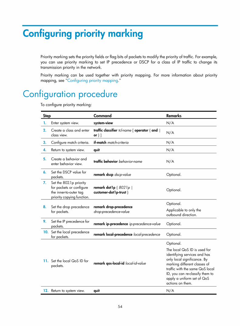
54
Configuring priority marking
Priority marking sets the priority fields or flag bits of packets to modify the priority of traffic. For example, you can use priority marking to set IP precedence or DSCP for a class of IP traffic to change its transmission priority in the network.
Priority marking can be used together with priority mapping. For more information about priority mapping, see "Configuring priority mapping."
Configuration procedure To configure priority marking:
Step Command Remarks
1. Enter system view. system-view N/A
2. Create a class and enter class view.
traffic classifier tcl-name [ operator { and | or } ] N/A
3. Configure match criteria. if-match match-criteria N/A
4. Return to system view. quit N/A
5. Create a behavior and enter behavior view. traffic behavior behavior-name N/A
6. Set the DSCP value for packets.
remark dscp dscp-value Optional.
7. Set the 802.1p priority for packets or configure the inner-to-outer tag priority copying function.
remark dot1p { 8021p | customer-dot1p-trust } Optional.
8. Set the drop precedence for packets.
remark drop-precedence drop-precedence-value
Optional.
Applicable to only the outbound direction.
9. Set the IP precedence for packets. remark ip-precedence ip-precedence-value Optional.
10. Set the local precedence for packets. remark local-precedence local-precedence Optional.
11. Set the local QoS ID for packets.
remark qos-local-id local-id-value
Optional.
The local QoS ID is used for identifying services and has only local significance. By marking different classes of traffic with the same QoS local ID, you can re-classify them to apply a uniform set of QoS actions on them.
12. Return to system view. quit N/A

55
Step Command Remarks 13. Create a policy and
enter policy view. qos policy policy-name N/A
14. Associate the class with the traffic behavior in the QoS policy.
classifier tcl-name behavior behavior-name N/A
15. Return to system view. quit N/A
16. Apply the QoS policy.
• Applying the QoS policy to an interface • Applying the QoS policy to online users • Applying the QoS policy to a VLAN • Applying the QoS policy globally
Choose one application destination as needed.
17. Display the priority marking configuration.
display traffic behavior user-defined [ behavior-name ] [ | { begin | exclude | include } regular-expression ]
Optional.
Available in any view
The following table shows the support for priority marking actions in the inbound and outbound directions.
Table 4 Support for priority marking actions in the inbound and outbound directions
Action inbound outbound
802.1p priority marking Yes Yes
Drop precedence marking Yes No
DSCP marking Yes Yes
IP precedence marking Yes Yes
Local precedence marking Yes No
Local QoS ID marking Yes Yes
Local precedence re-marking configuration example
Network requirements As shown in Figure 19, the company’s enterprise network interconnects hosts with servers through Device. The network is described as follows:
• Host A and Host B are connected to GigabitEthernet 1/0/1 of Device.
• The data server, mail server, and file server are connected to GigabitEthernet 1/0/2 of Device.
Configure priority marking on Device to satisfy the following requirements:
Traffic source Destination Processing priority
Host A, B Data server High
Host A, B Mail server Medium
Host A, B File server Low

56
Figure 19 Network diagram
Configuration procedure # Create advanced ACL 3000, and configure a rule to match packets with destination IP address 192.168.0.1. <Device> system-view
[Device] acl number 3000
[Device-acl-adv-3000] rule permit ip destination 192.168.0.1 0
[Device-acl-adv-3000] quit
# Create advanced ACL 3001, and configure a rule to match packets with destination IP address 192.168.0.2. [Device] acl number 3001
[Device-acl-adv-3001] rule permit ip destination 192.168.0.2 0
[Device-acl-adv-3001] quit
# Create advanced ACL 3002, and configure a rule to match packets with destination IP address 192.168.0.3. [Device] acl number 3002
[Device-acl-adv-3002] rule permit ip destination 192.168.0.3 0
[Device-acl-adv-3002] quit
# Create a class named classifier_dbserver, and use ACL 3000 as the match criterion in the class. [Device] traffic classifier classifier_dbserver
[Device-classifier-classifier_dbserver] if-match acl 3000
[Device-classifier-classifier_dbserver] quit
# Create a class named classifier_mserver, and use ACL 3001 as the match criterion in the class. [Device] traffic classifier classifier_mserver
[Device-classifier-classifier_mserver] if-match acl 3001
[Device-classifier-classifier_mserver] quit
# Create a class named classifier_fserver, and use ACL 3002 as the match criterion in the class. [Device] traffic classifier classifier_fserver
[Device-classifier-classifier_fserver] if-match acl 3002
[Device-classifier-classifier_fserver] quit
57
# Create a behavior named behavior_dbserver, and configure the action of setting the local precedence value to 4. [Device] traffic behavior behavior_dbserver
[Device-behavior-behavior_dbserver] remark local-precedence 4
[Device-behavior-behavior_dbserver] quit
# Create a behavior named behavior_mserver, and configure the action of setting the local precedence value to 3. [Device] traffic behavior behavior_mserver
[Device-behavior-behavior_mserver] remark local-precedence 3
[Device-behavior-behavior_mserver] quit
# Create a behavior named behavior_fserver, and configure the action of setting the local precedence value to 2. [Device] traffic behavior behavior_fserver
[Device-behavior-behavior_fserver] remark local-precedence 2
[Device-behavior-behavior_fserver] quit
# Create a policy named policy_server, and associate classes with behaviors in the policy. [Device] qos policy policy_server
[Device-qospolicy-policy_server] classifier classifier_dbserver behavior behavior_dbserver
[Device-qospolicy-policy_server] classifier classifier_mserver behavior behavior_mserver
[Device-qospolicy-policy_server] classifier classifier_fserver behavior behavior_fserver
[Device-qospolicy-policy_server] quit
# Apply the policy named policy_server to the incoming traffic of GigabitEthernet 1/0/1. [Device] interface gigabitethernet 1/0/1
[Device-GigabitEthernet1/0/1] qos apply policy policy_server inbound
[Device-GigabitEthernet1/0/1] quit
Local QoS ID marking configuration example Local QoS ID marking is mainly used for re-classifying packets of multiple classes to perform a uniform set of actions on them as a re-classified class.
Consider the case of limiting the total rate of packets with source MAC address 0001-0001-0001 and packets with source IP address 1.1.1.1 to 128 kbps. Without QoS local ID marking, you can only assign fixed bandwidth to the two classes by associating each of them with a rate-limit traffic behavior. With QoS local ID marking, however, traffic limit applies to the two classes as a whole, allowing the switch to dynamically assign the bandwidth to the two classes depending on their traffic size.
To configure local QoS ID marking to limit the total rate of the two classes, you need to mark packets of the two classes with the same local QoS ID; create a class to match the QoS local ID, and associate this class with the traffic policing action.
# Create ACL 2000 to match packets with source IP address 1.1.1.1. <Sysname> system-view
[Sysname] acl number 2000
[Sysname-acl-basic-2000] rule permit source 1.1.1.1 0
[Sysname-acl-basic-2000] quit
58
# Create a class class_a to match both packets with source MAC address 0001-0001-0001 and packets with source IP 1.1.1.1. <Sysname> system-view
[Sysname] traffic classifier class_a operator or
[Sysname-classifier-class_a] if-match source-mac 1-1-1
[Sysname-classifier-class_a] if-match acl 2000
[Sysname-classifier-class_a] quit
# Create a behavior behavior_a, and configure the action of marking packets with local QoS ID 100 for the behavior. [Sysname] traffic behavior behavior_a
[Sysname-behavior-behavior_a] remark qos-local-id 100
[Sysname-behavior-behavior_a] quit
# Create a class class_b to match packets with local QoS ID 100. [Sysname] traffic classifier class_b
[Sysname-classifier-class_b] if-match qos-local-id 100
[Sysname-classifier-class_b] quit
# Create a behavior behavior_b, and configure the action of limiting traffic rate to 128 kbps for the behavior. [Sysname] traffic behavior behavior_b
[Sysname-behavior-behavior_b] car cir 128
[Sysname-behavior-behavior_b] quit
# Create a QoS policy car_policy. In the QoS policy, associate class class_a with behavior behavior_a, and associate class class_b with behavior behavior_b. [Sysname] qos policy car_policy
[Sysname-qospolicy-car_policy] classifier class_a behavior behavior_a
[Sysname-qospolicy-car_policy] classifier class_b behavior behavior_b
Apply the QoS policy car_policy to the interface, satisfying the network requirements.
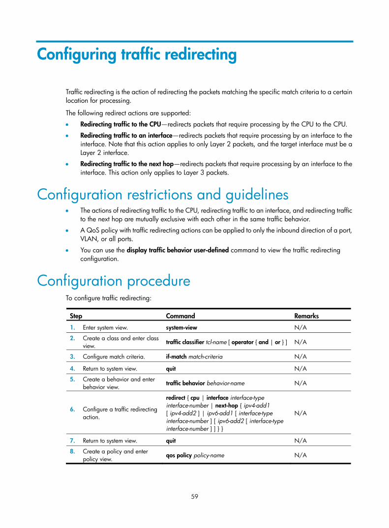
59
Configuring traffic redirecting
Traffic redirecting is the action of redirecting the packets matching the specific match criteria to a certain location for processing.
The following redirect actions are supported:
• Redirecting traffic to the CPU—redirects packets that require processing by the CPU to the CPU.
• Redirecting traffic to an interface—redirects packets that require processing by an interface to the interface. Note that this action applies to only Layer 2 packets, and the target interface must be a Layer 2 interface.
• Redirecting traffic to the next hop—redirects packets that require processing by an interface to the interface. This action only applies to Layer 3 packets.
Configuration restrictions and guidelines • The actions of redirecting traffic to the CPU, redirecting traffic to an interface, and redirecting traffic
to the next hop are mutually exclusive with each other in the same traffic behavior.
• A QoS policy with traffic redirecting actions can be applied to only the inbound direction of a port, VLAN, or all ports.
• You can use the display traffic behavior user-defined command to view the traffic redirecting configuration.
Configuration procedure To configure traffic redirecting:
Step Command Remarks
1. Enter system view. system-view N/A
2. Create a class and enter class view.
traffic classifier tcl-name [ operator { and | or } ] N/A
3. Configure match criteria. if-match match-criteria N/A
4. Return to system view. quit N/A
5. Create a behavior and enter behavior view. traffic behavior behavior-name N/A
6. Configure a traffic redirecting action.
redirect { cpu | interface interface-type interface-number | next-hop { ipv4-add1 [ ipv4-add2 ] | ipv6-add1 [ interface-type interface-number ] [ ipv6-add2 [ interface-type interface-number ] ] } }
N/A
7. Return to system view. quit N/A
8. Create a policy and enter policy view. qos policy policy-name N/A

60
Step Command Remarks 9. Associate the class with the
traffic behavior in the QoS policy.
classifier tcl-name behavior behavior-name N/A
10. Return to system view. quit N/A
11. Apply the QoS policy. • Applying the QoS policy to an interface • Applying the QoS policy to a VLAN • Applying the QoS policy globally
Choose one application destination as needed.
Redirect-to-next hop configuration example
Network requirements As shown in Figure 20, the network is described as follows:
• Device A is connected to Device through two links. At the same time, Device A and Device B are each connected to other devices.
• GigabitEthernet 1/0/2 of Device A and GigabitEthernet 1/0/2 of Device B belong to VLAN 200.
• Ethernet 1/3 of Device A and Ethernet 1/3 of Device B belong to VLAN 201.
• On Device A, the IP address of VLAN-interface 200 is 200.1.1.1/24, and that of VLAN-interface 201 is 201.1.1.1/24.
• On Device B, the IP address of VLAN-interface 200 is 200.1.1.2/24, and that of VLAN-interface 201 is 201.1.1.2/24.
Configure the actions of redirecting traffic to the next hop to implement policy-based routing and satisfy the following requirements:
• Packets with source IP address 2.1.1.1 received on GigabitEthernet 1/0/1 of Device A are forwarded to IP address 200.1.1.2.
• Packets with source IP address 2.1.1.2 received on GigabitEthernet 1/0/1 of Device A are forwarded to IP address 201.1.1.2.
• Other packets received on GigabitEthernet 1/0/1 of Device A are forwarded according to the routing table.
Figure 20 Network diagram
Configuration procedure # Create basic ACL 2000, and configure a rule to match packets with source IP address 2.1.1.1. <DeviceA> system-view
[DeviceA] acl number 2000

61
[DeviceA-acl-basic-2000] rule permit source 2.1.1.1 0
[DeviceA-acl-basic-2000] quit
# Create basic ACL 2001, and configure a rule to match packets with source IP address 2.1.1.2. [DeviceA] acl number 2001
[DeviceA-acl-basic-2001] rule permit source 2.1.1.2 0
[DeviceA-acl-basic-2001] quit
# Create a class named classifier_1, and use ACL 2000 as the match criterion in the class. [DeviceA] traffic classifier classifier_1
[DeviceA-classifier-classifier_1] if-match acl 2000
[DeviceA-classifier-classifier_1] quit
# Create a class named classifier_2, and use ACL 2001 as the match criterion in the class. [DeviceA] traffic classifier classifier_2
[DeviceA-classifier-classifier_2] if-match acl 2001
[DeviceA-classifier-classifier_2] quit
# Create a behavior named behavior_1, and configure the action of redirecting traffic to the next hop 200.1.1.2. [DeviceA] traffic behavior behavior_1
[DeviceA-behavior-behavior_1] redirect next-hop 200.1.1.2
[DeviceA-behavior-behavior_1] quit
# Create a behavior named behavior_2, and configure the action of redirecting traffic to the next hop 200.1.1.2. [DeviceA] traffic behavior behavior_2
[DeviceA-behavior-behavior_2] redirect next-hop 201.1.1.2
[DeviceA-behavior-behavior_2] quit
# Create a policy named policy, associate class classifier_1 with behavior behavior_1, and associate class classifier_2 with behavior behavior_2 in the policy. [DeviceA] qos policy policy
[DeviceA-qospolicy-policy] classifier classifier_1 behavior behavior_1
[DeviceA-qospolicy-policy] classifier classifier_2 behavior behavior_2
[DeviceA-qospolicy-policy] quit
# Apply the policy named policy to the incoming traffic of GigabitEthernet 1/0/1. [DeviceA] interface gigabitethernet 1/0/1
[DeviceA-GigabitEthernet1/0/1] qos apply policy policy inbound

62
Configuring aggregate CAR
Overview An aggregate CAR action is created globally and can be directly applied to interfaces or referenced in the traffic behaviors associated with different traffic classes to police multiple traffic flows as a whole. The total rate of the traffic flows must conform to the traffic policing specifications set in the aggregate CAR action.
Configuring aggregate CAR
Configuration restrictions and guidelines In a traffic behavior, do not configure an aggregate CAR action together with any priority marking action (including local precedence, drop precedence, 802.1p priority, DSCP value, and IP precedence marking actions). Otherwise, you will fail to apply the QoS policy properly.
Configuration procedure To configure aggregate CAR:
Step Command Remarks
1. Enter system view. system-view N/A
2. Configure an aggregate CAR action.
qos car car-name aggregative cir committed-information-rate [ cbs committed-burst-size [ ebs excess-burst-size ] ] [ pir peek-information-rate ] [ green action ] [ yellow action ] [ red action ]
N/A
3. Enter behavior view. traffic behavior behavior-name N/A
4. Reference the aggregate CAR in the traffic behavior.
car name car-name N/A
5. Display the traffic behavior configuration information.
display traffic behavior user-defined [ behavior-name ] [ | { begin | exclude | include } regular-expression ]
Optional.
Available in any view
6. Display the configuration and statistics for the specified aggregate CAR.
display qos car name [ car-name ] [ | { begin | exclude | include } regular-expression ]
Optional.
Available in any view

63
Displaying and maintaining aggregate CAR configuration
Task Command Remarks
Display statistics for aggregate CAR actions.
display qos car name [ car-name ] [ | { begin | exclude | include } regular-expression ]
Available in any view
Clear statistics for aggregate CAR actions.
reset qos car name [ car-name ] Available in user view
Aggregate CAR configuration example
Network requirements As shown in Figure 21, configure an aggregate CAR to rate-limit the traffic of VLAN 10 and VLAN 100 received on GigabitEthernet 1/0/1 using these parameters: CIR is 256 kbps, CBS is 2000 bytes, and the action for red packets is discard.
Figure 21 Network diagram
Configuration procedure # Configure an aggregate CAR according to the rate limit requirements. <Sysname> system-view
[Sysname] qos car aggcar-1 aggregative cir 256 cbs 2000 red discard
# Create class 1 to match traffic of VLAN 10; create behavior 1, and reference the aggregate CAR in the behavior.
64
[Sysname] traffic classifier 1
[Sysname-classifier-1] if-match service-vlan-id 10
[Sysname-classifier-1] quit
[Sysname] traffic behavior 1
[Sysname-behavior-1] car name aggcar-1
[Sysname-behavior-1] quit
# Create class 2 to match traffic of VLAN 100; create behavior 2, and reference the aggregate CAR in the behavior. [Sysname] traffic classifier 2
[Sysname-classifier-2] if-match service-vlan-id 100
[Sysname-classifier-2] quit
[Sysname] traffic behavior 2
[Sysname-behavior-2] car name aggcar-1
[Sysname-behavior-2] quit
# Create QoS policy car, associate class 1 with behavior 1, and associate class 2 with behavior 2. [Sysname] qos policy car
[Sysname-qospolicy-car] classifier 1 behavior 1
[Sysname-qospolicy-car] classifier 2 behavior 2
[Sysname-qospolicy-car] quit
# Apply the QoS policy to the incoming traffic of GigabitEthernet 1/0/1. [Sysname] interface GigabitEthernet 1/0/1
[Sysname-GigabitEthernet1/0/1]qos apply policy car inbound

65
Configuring class-based accounting
Class-based accounting collects statistics (in packets or bytes) on a per-traffic class basis. For example, you can define the action to collect statistics for traffic sourced from a certain IP address. By analyzing the statistics, you can determine whether anomalies have occurred and what action to take.
Configuration procedure To configure class-based accounting:
Step Command Remarks
1. Enter system view. system-view N/A
2. Create a class and enter class view.
traffic classifier tcl-name [ operator { and | or } ] N/A
3. Configure match criteria. if-match match-criteria N/A
4. Return to system view. quit N/A
5. Create a behavior and enter behavior view.
traffic behavior behavior-name N/A
6. Configure the accounting action. accounting { byte | packet }
• byte—Counts traffic in bytes.
• packet—Counts traffic in packets.
7. Return to system view. quit N/A
8. Create a policy and enter policy view.
qos policy policy-name N/A
9. Associate the class with the traffic behavior in the QoS policy.
classifier tcl-name behavior behavior-name N/A
10. Return to system view. quit N/A
11. Apply the QoS policy.
• Applying the QoS policy to an interface
• Applying the QoS policy to a VLAN • Applying the QoS policy globally
Choose one application destination as needed.
Displaying and maintaining traffic accounting You can verify the configuration with the display qos policy global, display qos policy interface, or display qos vlan-policy command depending on the occasion where the QoS policy is applied.
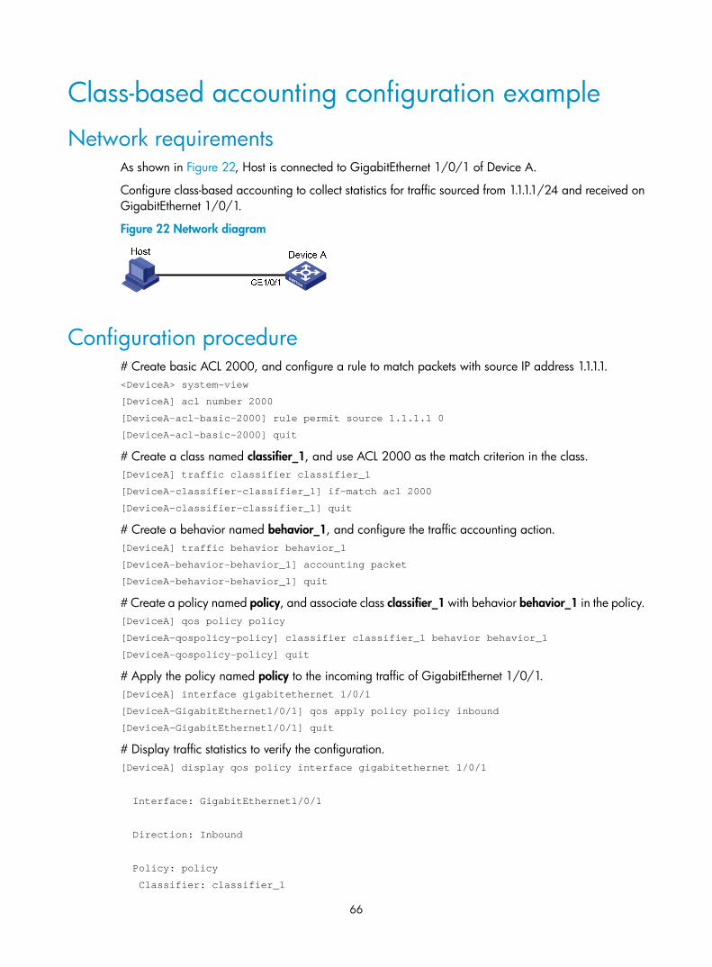
66
Class-based accounting configuration example
Network requirements As shown in Figure 22, Host is connected to GigabitEthernet 1/0/1 of Device A.
Configure class-based accounting to collect statistics for traffic sourced from 1.1.1.1/24 and received on GigabitEthernet 1/0/1.
Figure 22 Network diagram
Configuration procedure # Create basic ACL 2000, and configure a rule to match packets with source IP address 1.1.1.1. <DeviceA> system-view
[DeviceA] acl number 2000
[DeviceA-acl-basic-2000] rule permit source 1.1.1.1 0
[DeviceA-acl-basic-2000] quit
# Create a class named classifier_1, and use ACL 2000 as the match criterion in the class. [DeviceA] traffic classifier classifier_1
[DeviceA-classifier-classifier_1] if-match acl 2000
[DeviceA-classifier-classifier_1] quit
# Create a behavior named behavior_1, and configure the traffic accounting action. [DeviceA] traffic behavior behavior_1
[DeviceA-behavior-behavior_1] accounting packet
[DeviceA-behavior-behavior_1] quit
# Create a policy named policy, and associate class classifier_1 with behavior behavior_1 in the policy. [DeviceA] qos policy policy
[DeviceA-qospolicy-policy] classifier classifier_1 behavior behavior_1
[DeviceA-qospolicy-policy] quit
# Apply the policy named policy to the incoming traffic of GigabitEthernet 1/0/1. [DeviceA] interface gigabitethernet 1/0/1
[DeviceA-GigabitEthernet1/0/1] qos apply policy policy inbound
[DeviceA-GigabitEthernet1/0/1] quit
# Display traffic statistics to verify the configuration. [DeviceA] display qos policy interface gigabitethernet 1/0/1
Interface: GigabitEthernet1/0/1
Direction: Inbound
Policy: policy
Classifier: classifier_1

67
Operator: AND
Rule(s) : If-match acl 2000
Behavior: behavior_1
Accounting Enable:
28529 (Packets)

68
Configuring burst
The burst function improves packet buffering and forwarding performance in the following scenarios:
• Dense broadcast or multicast traffic and massive burst traffic are present.
• High-speed traffic is forwarded over a low-speed link or traffic received from multiple interfaces at the same speed is forwarded through an interface at the same speed.
By enabling the burst function on your device, you can improve the processing performance of the device operating in these scenarios to reduce packet loss.
Make sure that you are fully aware of the impacts when enabling the burst function, because the burst function may affect the QoS performance of your device.
Configuration prerequisites Make sure that the burst function is necessary for addressing your problem.
Configuration procedure To enable the burst function:
Step Command Remarks
1. Enter system view. system-view N/A
2. Enable the burst function. burst-mode enable Disabled by default
Burst configuration example
Network requirements In the customer network shown in Figure 23, a server connects to the switch through a 1000 Mbps Ethernet interface. The server sends dense broadcast or multicast traffic to the hosts irregularly. Each host connects to the switch through a 100 Mbps network adapter.
Configure the switch to process dense traffic from the server to guarantee that packets can reach the hosts.

69
Figure 23 Network diagram for burst configuration
Configuration procedure # Enter system view. <Switch> system-view
# Enable the burst function. [Switch] burst-mode enable

70
Appendix A Default priority mapping tables
Uncolored priority mapping tables For the default dscp-dscp mapping table, an input value yields a target value equal to it.
Table 5 Default dot1p-lp and dot1p-dp priority mapping tables
Input priority value dot1p-lp mapping dot1p-dp mapping
802.1p priority (dot1p) Local precedence (lp) Drop precedence (dp) 0 2 0
1 0 0
2 1 0
3 3 0
4 4 0
5 5 0
6 6 0
7 7 0
Table 6 Default dscp-dp and dscp-dot1p priority mapping tables
Input priority value dscp-dp mapping dscp-dot1p mapping
DSCP Drop precedence (dp) 802.1p priority (dot1p) 0 to 7 0 0
8 to 15 0 1
16 to 23 0 2
24 to 31 0 3
32 to 39 0 4
40 to 47 0 5
48 to 55 0 6
56 to 63 0 7

71
Appendix B Packet precedences
IP precedence and DSCP values Figure 24 ToS and DS fields
As shown in Figure 24, the ToS field in the IPv4 header contains eight bits, where the first three bits (0 to 2) represent IP precedence from 0 to 7; the Traffic Classes field in the IPv6 header contains eight bits, where the first three bits (0 to 2) represent IP precedence from 0 to 7. According to RFC 2474, the ToS field in the IPv4 header or the Traffic Classes field in the IPv6 header is redefined as the differentiated services (DS) field, where a DSCP value is represented by the first six bits (0 to 5) and is in the range 0 to 63. The remaining two bits (6 and 7) are reserved.
Table 7 Description on IP precedence
IP precedence (decimal) IP precedence (binary) Description
0 000 Routine
1 001 priority
2 010 immediate
3 011 flash
4 100 flash-override
5 101 critical
6 110 internet
7 111 network
Table 8 Description on DSCP values
DSCP value (decimal) DSCP value (binary) Description
46 101110 ef
10 001010 af11
12 001100 af12
14 001110 af13
18 010010 af21
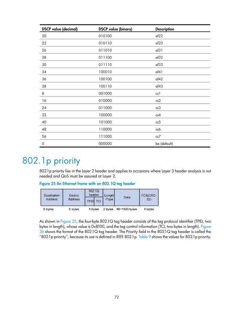
72
DSCP value (decimal) DSCP value (binary) Description
20 010100 af22
22 010110 af23
26 011010 af31
28 011100 af32
30 011110 af33
34 100010 af41
36 100100 af42
38 100110 af43
8 001000 cs1
16 010000 cs2
24 011000 cs3
32 100000 cs4
40 101000 cs5
48 110000 cs6
56 111000 cs7
0 000000 be (default)
802.1p priority 802.1p priority lies in the Layer 2 header and applies to occasions where Layer 3 header analysis is not needed and QoS must be assured at Layer 2.
Figure 25 An Ethernet frame with an 802.1Q tag header
As shown in Figure 25, the four-byte 802.1Q tag header consists of the tag protocol identifier (TPID, two bytes in length), whose value is 0x8100, and the tag control information (TCI, two bytes in length). Figure 26 shows the format of the 802.1Q tag header. The Priority field in the 802.1Q tag header is called the "802.1p priority", because its use is defined in IEEE 802.1p. Table 9 shows the values for 802.1p priority.
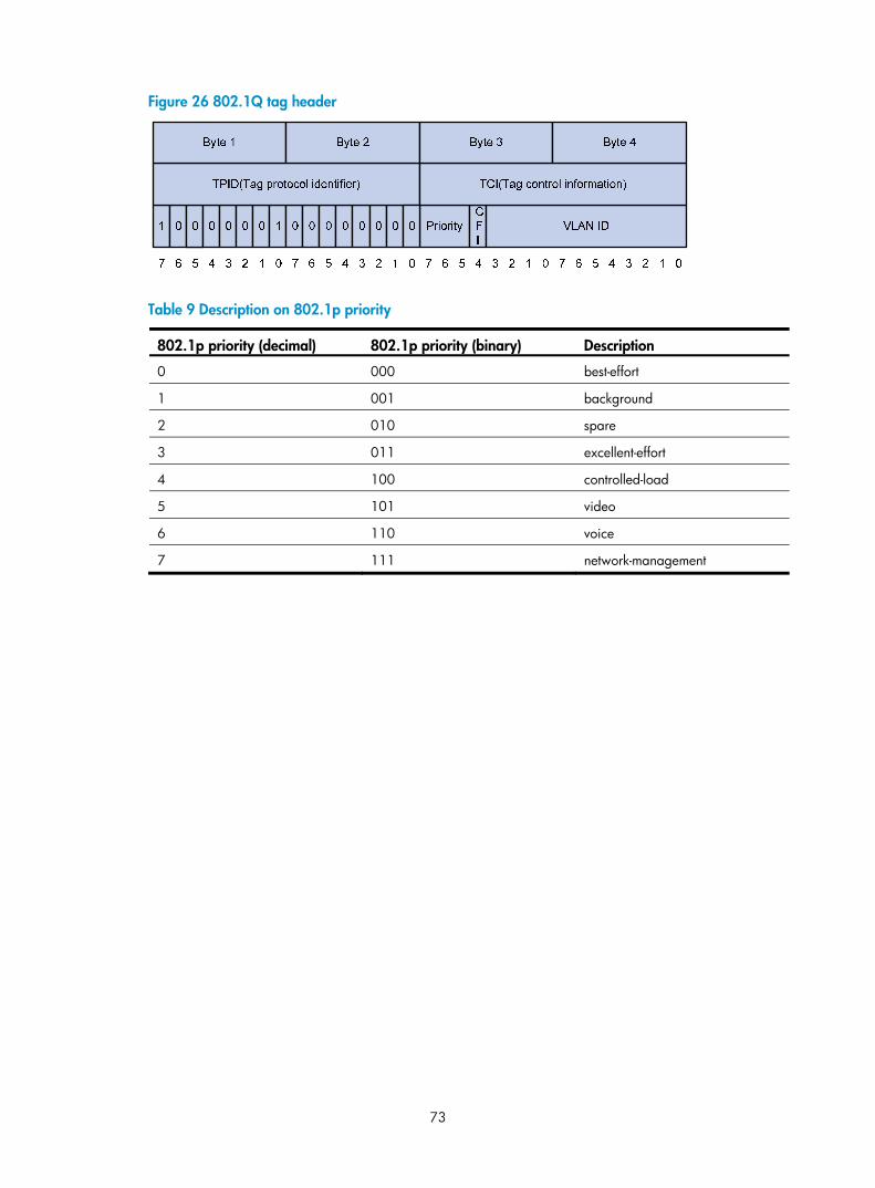
73
Figure 26 802.1Q tag header
Table 9 Description on 802.1p priority
802.1p priority (decimal) 802.1p priority (binary) Description
0 000 best-effort
1 001 background
2 010 spare
3 011 excellent-effort
4 100 controlled-load
5 101 video
6 110 voice
7 111 network-management

74
Support and other resources
Contacting HP For worldwide technical support information, see the HP support website:
http://www.hp.com/support
Before contacting HP, collect the following information:
• Product model names and numbers
• Technical support registration number (if applicable)
• Product serial numbers
• Error messages
• Operating system type and revision level
• Detailed questions
Subscription service HP recommends that you register your product at the Subscriber's Choice for Business website:
http://www.hp.com/go/wwalerts
After registering, you will receive email notification of product enhancements, new driver versions, firmware updates, and other product resources.
Related information
Documents To find related documents, browse to the Manuals page of the HP Business Support Center website:
http://www.hp.com/support/manuals
• For related documentation, navigate to the Networking section, and select a networking category.
• For a complete list of acronyms and their definitions, see HP A-Series Acronyms.
Websites • HP.com http://www.hp.com
• HP Networking http://www.hp.com/go/networking
• HP manuals http://www.hp.com/support/manuals
• HP download drivers and software http://www.hp.com/support/downloads
• HP software depot http://www.software.hp.com
• HP Education http://www.hp.com/learn

75
Conventions This section describes the conventions used in this documentation set.
Command conventions
Convention Description
Boldface Bold text represents commands and keywords that you enter literally as shown.
Italic Italic text represents arguments that you replace with actual values.
[ ] Square brackets enclose syntax choices (keywords or arguments) that are optional.
{ x | y | ... } Braces enclose a set of required syntax choices separated by vertical bars, from which you select one.
[ x | y | ... ] Square brackets enclose a set of optional syntax choices separated by vertical bars, from which you select one or none.
{ x | y | ... } * Asterisk-marked braces enclose a set of required syntax choices separated by vertical bars, from which you select at least one.
[ x | y | ... ] * Asterisk-marked square brackets enclose optional syntax choices separated by vertical bars, from which you select one choice, multiple choices, or none.
&<1-n> The argument or keyword and argument combination before the ampersand (&) sign can be entered 1 to n times.
# A line that starts with a pound (#) sign is comments.
GUI conventions
Convention Description
Boldface Window names, button names, field names, and menu items are in bold text. For example, the New User window appears; click OK.
> Multi-level menus are separated by angle brackets. For example, File > Create > Folder.
Symbols
Convention Description
WARNING An alert that calls attention to important information that if not understood or followed can result in personal injury.
CAUTION An alert that calls attention to important information that if not understood or followed can result in data loss, data corruption, or damage to hardware or software.
IMPORTANT An alert that calls attention to essential information.
NOTE An alert that contains additional or supplementary information.
TIP An alert that provides helpful information.

76
Network topology icons
Represents a generic network device, such as a router, switch, or firewall.
Represents a routing-capable device, such as a router or Layer 3 switch.
Represents a generic switch, such as a Layer 2 or Layer 3 switch, or a router that supports Layer 2 forwarding and other Layer 2 features.
Port numbering in examples
The port numbers in this document are for illustration only and might be unavailable on your device.
77
Index
A B C D I L M N O P Q R T U A
ACL configuration task list,3 Aggregate CAR configuration example,63 Applying the QoS policy,21
B
Burst configuration example,68
C
Changing the port priority of an interface,27 Class-based accounting configuration example,66 Configuration example of using ACL for device management,11 Configuration guidelines,27 Configuration prerequisites,68 Configuration procedure,52 Configuration procedure,54 Configuration procedure,68 Configuration procedure,65 Configuration procedure,59 Configuration restrictions and guidelines,59 Configuring a basic ACL,4 Configuring a port to trust packet priority for priority mapping,27 Configuring a priority mapping table,27 Configuring a time range,4 Configuring aggregate CAR,62 Configuring an advanced ACL,6 Configuring an Ethernet frame header ACL,9 Configuring GTS,36 Configuring SP queuing,43 Configuring SP+WFQ queuing,47 Configuring SP+WRR queuing,46 Configuring the line rate,36 Configuring traffic policing,35 Configuring WFQ queuing,45 Configuring WRED,50 Configuring WRR queuing,44 Congestion management techniques,40
Contacting HP,74 Conventions,75 Copying an ACL,9
D
Defining a class,18 Defining a policy,21 Defining a traffic behavior,20 Displaying and maintaining ACLs,11 Displaying and maintaining aggregate CAR configuration,63 Displaying and maintaining QoS policies,23 Displaying and maintaining traffic accounting,65 Displaying and maintaining traffic policing, GTS, and line rate,37 Displaying and maintaining WRED,51 Displaying priority mappings,28
I
Introduction to WRED configuration,49 IP precedence and DSCP values,71 IPv4 packet filtering configuration example,13 IPv6 packet filtering configuration example,14
L
Local precedence re-marking configuration example,55 Local QoS ID marking configuration example,57
M
MQC approach,17
N
Non-MQC approach,17
O
Overview,18 Overview,40 Overview,32 Overview,49 Overview,1

78
Overview,62 Overview,25
P
Packet filtering with ACLs,10 Priority mapping table and priority marking configuration example,29 Priority trust mode configuration example,28
Q
QoS service models,15 QoS techniques,16
R
Redirect-to-next hop configuration example,60 Related information,74
T
Traffic filtering configuration example,53 Traffic policing configuration example,37
U
Uncolored priority mapping tables,70