Howard Rotavator Gem and Super Gem Operating ... Rotavator Gem and Super Gem Operating Instructions...
15
Howard" Rotavator" Gem " and Super Gem Operating + >. Instructions - - .:
Transcript of Howard Rotavator Gem and Super Gem Operating ... Rotavator Gem and Super Gem Operating Instructions...
Howard" Rotavator" Gem " and Super Gem Operating + >. Instructions - - .:
GENERAL SAFETY PRECAUTIONS
1. Read and familiarise yourself with the operating instruction book.
2. Do not allow children to operate the machine. Do not allow adults to operate the machine without proper instructions.
3. Clear the work area of objects which might be picked up and thrown.
4. Before attempting to start -the machine ensure the gear lever i s in neutral and the rotor drive disengaged.
5. Never tamper with the reverse gear mechanism, this is a safety device.
6. Disengage the rotor drive before reversing or turning the machine.
7. Work up and down the face of steep slopes, never across them.
8. Handle petrol with care - Use an approved petrol container. Never remove the cap of the fuel tank or add petrol to a running or hot engine, or fill the tank indoors. Wipe up spilled petrol.
9. Open doors if the engine is run in the garage - exhaust fumes are dangerous.
1.0. Keep all nuts, bolts and screws tight and be sure that the equipment is regularly lubricated to keep it in a safe working condition.
11. Keep all safety guards in place.
12. Never touch the rotor with the engine running - switch off first.
13. Always wear substantial footwear to provide as much protection as possible.
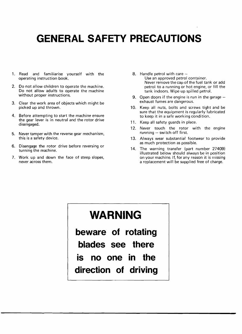
14. The warning transfer (part number 27409) illustrated below should always be in position on your machine. If, for any reason it is missing a replacement will be supplied free of charge.
WARNING beware of rotating blades see there is no one in the direction of driving
Howard Rotavator Gem and Super Gem Operating Instructions
CONTENTS
Aircleaner . . . . . . . . . . . . . . . . . . . . . . . . . 8 Blade maintenance . . . . . . . . . . . . . . . . . . . . . . 8 Cleaning chaincase . . . . . . . . . . . . . . . . . . . . . . 8 Cleaning gearbox . . . . . . . . . . . . . . . . . . . . . . . 8 Drive chain . . . . . . . . . . . . . . . . . . . . . . . . . 8 Roadwheels . . . . . . . . . . . . . . . . . . . . . . . . 8 Rotor flange weedcutters . . . . . . . . . . . . . . . . . . . . 8 Rotor friction drive . . . . . . . . . . . . . . . . . . . . . . 8
Attachments . . . . . . . . . . . . . . . . . . . . . . . . . 10
Depth control wheel . . . . . . . . . . . . . . . . . . . . . 10 Furrower . . . . . . . . . . . . . . . . . . . . . . . . . . 10 Pictine rotor . . . . . . . . . . . . . . . . . . . . . . . . 10
. . . . . . . . . . . . . . . . . . . . . . . . . . . . Controis 3 . . . . . . . . . . . . . . . . . . . . Lubrication and maintenance 5
Lubrication and maintenance chart . . . . . . . . . . . . . . . . 6 & 7 Making the most of your Gem . . . . . . . . . . . . . . . . . . . . 11
. . . . . . . . . . . . . . . . . . . . . . . . . Rotor and blades 9 Serial number . . . . . . . . . . . . . . . . . . . . . . . . . . 2 Specifications . . . . . . . . . . . . . . . . . . . . . . . . . . 2
. . . . . . . . . . . . . . . . . . . . . . . Working the machine 4 . . . . . . . . . . . . . . . . . . . . . . . . Your new machine 3
The Howard Gem is THE heavy duty hand-controlled Rotavator for growers. farmers and contractors .
From seedbed making to land reclaiming. catch cropping to weed control. mixing-in manure to breaking up pasture. the work power and engineering quality of the Gem are unequalled .
The Gem has three forward gears providing the right speed for any type of work or soil condition . A reverse gear gives
ease of handling in confined areas; adjustable handlebars. up or down. side to side. aid operator comfort and flexibility of control .
Simple construction and a proven design keep maintenance to a minimum .
Optional attachments include a furrower. depth control wheel and front-end weights .
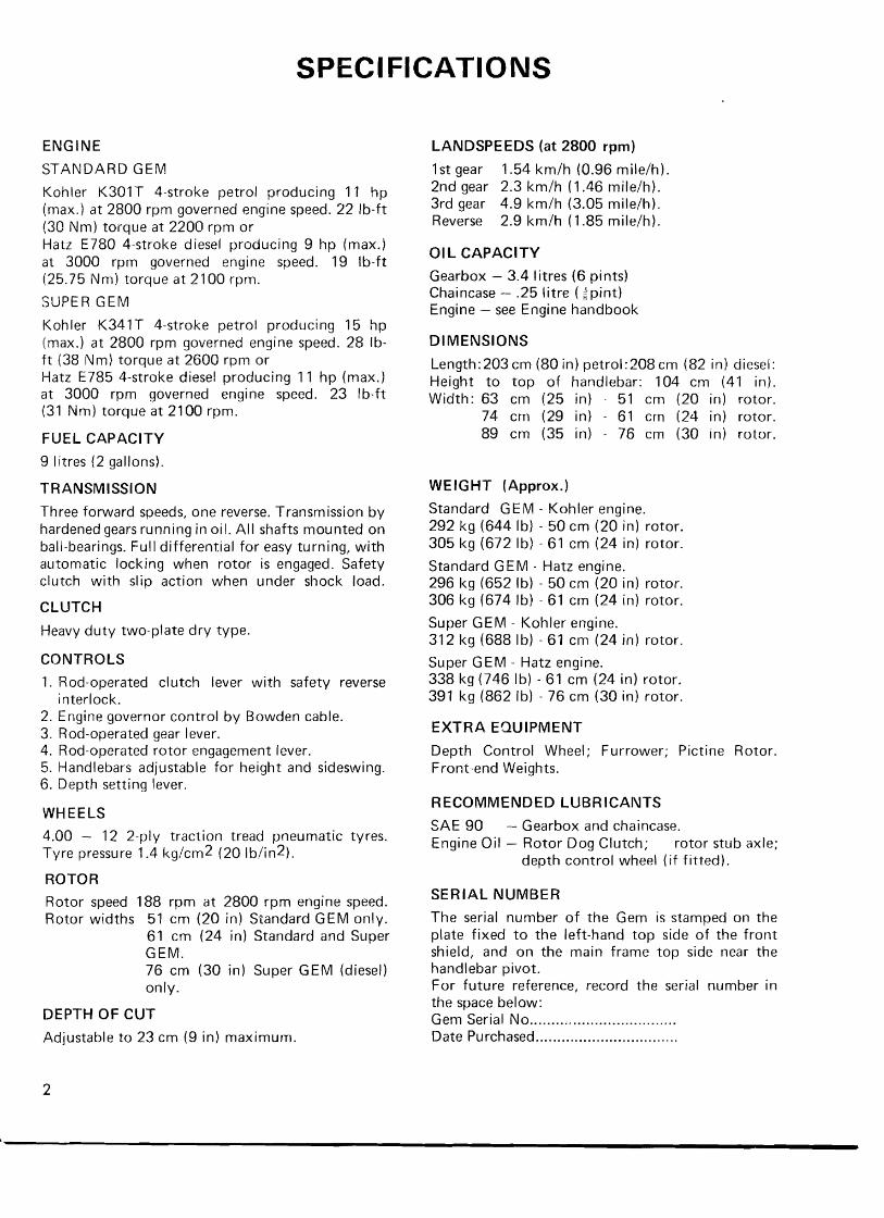
SPECIFICATIONS
ENGIIVE LANDSPEEDS (a t 2800 rpm)
STANDARD GEM
Kohler K301T 4-stroke petrol producing 11 hp (rnax.) a t 2800 rprn governed engine speed. 22 Ib-ft (30 Nm) torque a t 2200 rprn or Hatz E780 4-stroke diesel producing 9 hp (max.) a t 3000 rprn governed engine speed. 19 Ib-ft (25.75 Nm) torque a t 2100 rpm.
SUPER GEM
Kohler K341T 4-stroke petrol producing 15 hp (rnax.) a t 2800 rprn governed engine speed. 28 Ib- f t 138 Nm) torque a t 2600 rprn or Hatz E785 4-stroke diesel producing 11 hp (rnax.) a t 3000 rprn governed engine speed. 23 Ib-ft (31 Nm) torque a t 2100 rpm.
FUEL CAPACITY
9 litres (2 gallons).
TRANSMISSIQN
Three forward speeds, one reverse. Transmission by hardened gears running in oi I. All shafts mounted on ball-bearings. Full differential for easy turning, with automatic locking when rotor is engaged. Safety clutch with slip action when under shock load.
CLUTCH
Heavy duty two-plate dry type.
CONTROLS
1. Rod-operated clutch lever with safety reverse interlock.
2. Engine governor control by Bowden cable. 3. Rod-operated gear lever. 4. Rod-operated rotor engagement lever. 5. Handlebars adjustable for height and sideswing. 6. Depth setting lever.
WHEELS
4.00 - 12 2-ply traction tread pneumatic tyres. Tyre pressure 1.4 kg/cm2 (20 1b/in2).
ROTOR
Rotor speed 188 rprn a t 2800 rprn engine speed. Rotor widths 51 cm (20 in) Standard GEM only.
61 cm (24 in) Standard and Super GEM. 76 cm (30 in) Super GEM (diesel) on1 y.
DEPTH OF CUT
Adjustable to 23 cm (9 in) maximum.
1 s t gear 1.54 km/h (0.96 mile/h). 2nd gear 2.3 km/h (1.46 milelh). 3rd gear 4.9 km/h (3.05 mile/h). Reverse 2.9 km/h (1.85 mile/h).
OIL CAPACITY
Gearbox - 3.4 litres (6 pints) Chaincase - .25 litre ( ;pint) Engine - see Engine handbook
DIMENSIONS
Length: 203 cm (80 in) petrol:208 cm (82 in) diesel: Height to top of handlebar: 104 cm (41 in). Width: 63 cm (25 in) - 51 cm (20 in) rotor.
74 cm (29 in) - 61 cm (24 in) rotor. 89 cm (35 in) - 76 cm (30 in) rotor.
WEIGHT (Approx.)
Standard GEM - Kohler engine. 292 kg (644 Ib) - 50 cm (20 in) rotor. 305 kg (672 Ib) - 61 cm (24 in) rotor.
Standard GEM - Hatz engine. 296 kg (652 Ib) - 50 cm (20 in) rotor. 306 kg (674 Ib) - 61 cm (24 in) rotor.
Super GEM - Kohler engine. 312 kg (688 Ib) - 61 cm (24 in) rotor.
Super GEM - Hatz engine. 338 kg (746 Ib) - 61 cm (24 in) rotor. 391 kg (862 Ib) - 76 cm (30 in) rotor.
EXTRA EQUIPMENT
Depth Control Wheel; Furrower; Pictine Rotor. Front-end Weights.
RECOMMENDED LUBRlCAlVTS
SAE 90 - Gearbox and chaincase. Engine Oil - Rotor Dog Clutch; rotor stub axle;
depth control wheel ( i f fitted).
SERIAL NUMBER
The serial number of the Gem is stamped on the plate fixed to the left-hand top side of the front shield, and on the main frame top side near the handlebar pivot. For future reference, record the serial number in the space below:
.................................. Gem Serial No Date Purchased .................................
YOUR NEW MACHINE
On receipt of your new "Gem" first read and study the instruction manuals for both engine and machine. Satisfactory performance and a long working life for your Rotavator will depend upon your following the instruc- tions given. Be certain to keep the manuals in a safe, convenient place ready for quick reference.
When in need of spare parts or service, contact your Howard dealer. He has genuine replacement Howard parts, and trained, experienced staff to service your machine correctly.
Before starting to use your "Gem", first fill the fuel tank, check the gearbox and chaincase oil levels, and the lubrication points. Check that all nuts and bolts are tight.
Run the machine lightly at first, and gradually increase the loads during the first 25 hours work. NEVER allow the engine to labour during this running-in period.
After the first five hours of operation, check all nuts and bolts for tightness, including the two wheel hub centre nuts.
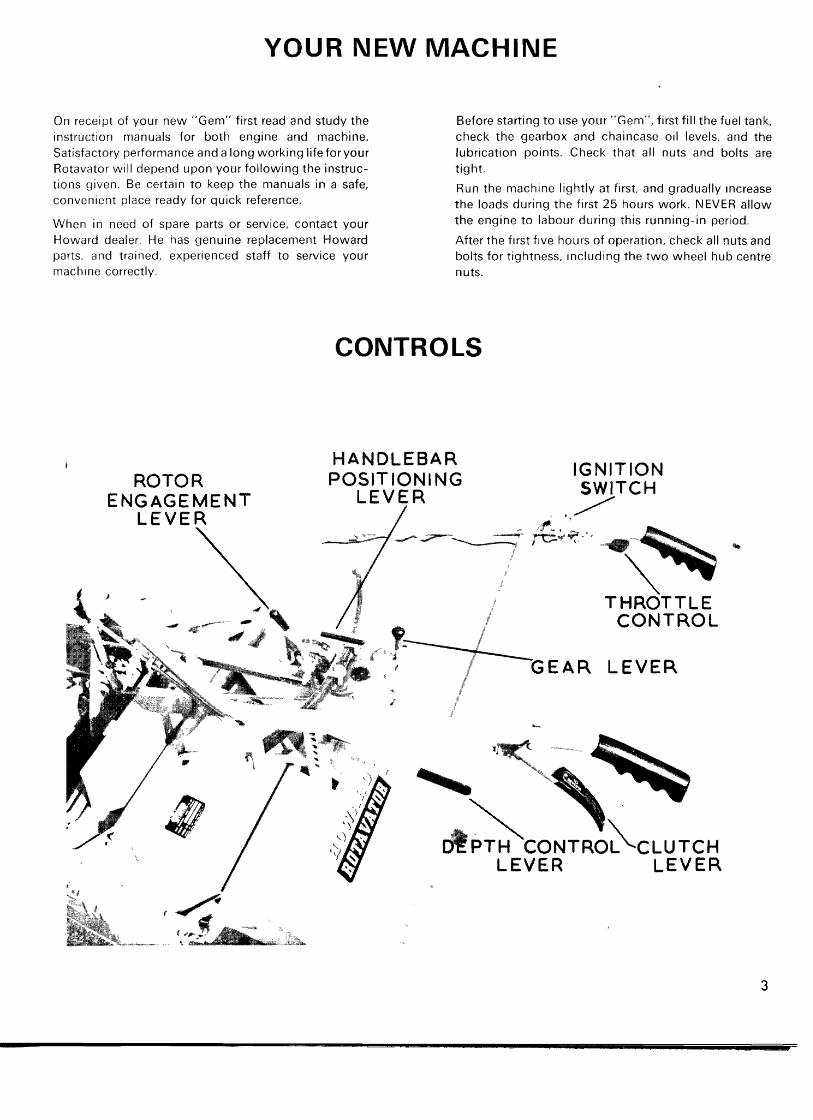
CONTROLS
HANDLEBAR ROTOR
IGNITION
ENGAGEMENT LEVER
9a
B THROTTLE CONTROL
EAR LEVER
WORKING THE MACHINE
Start the engine according to the engine instruction book. Lift the clutch lever and engage the required gear. DO NOT FORCE THE GEARS INTO MESH. If they do not immediately engage, release the clutch lever momentarily.
The slight noise which may be heard when the clutch is engaged is due to the positive action of the twin clutch plates.
When in a position to begin Rotavating, lift the clutch lever again, and move the rotor engagement lever to the "IN" position. Increase the engine speed and gently release the clutch, allowing the machine to pull itself into the work.
The rotor engagement lever also operates the differ- ential lock. The lever must therefore be put into the "OUT" position for turning.
The depth is controlled by pressing the depth control lever to the right. This releases the skid in the socket, allowing it to be repositioned as required. The skid itself has two alternative holes, the lower one of which per- mits a greater depth to be obtained.
Choose the depth to suit the crop being planted. It this is deeper than can be obtained in one pass without the engine labouring, several passes should be made at progressively increasing depths.
First gear should be used for heavy work, and where a fine tilth is required Second gear should be used for average conditions, and top gear for light hoeing and road work.
Where a coarse tilth is required, the rotor shield should be raised as high as possible with the trailing board folded back. The rotor should always be disengaged when reversing as well as when turning at headlands.
To stop the machine, raise the clutch lever, and move the gear lever to the centre (neutral) position. Move the rotor engagement lever to the "OUT" position and then release the clutch.
REVERSING To reverse, pull up the clutch lever, move the gear lever to Reverse (this simultaneously operates the safety interlock) and release the clutch lever. No movement occurs until the clutch lever is pushed down. Removal of pressure automatically stops the machine. To dis- engage levers, pull up the clutch lever and move the lever to neutral.
IVEVER, UNDER ANY CIRCUMSTAIVCES, TAMPER WlTH THE REVERSE GEAR LINKAGE. THE INTER- LOCK MECHANISM ISASAFETY DEVICE AND MUST NOT BE INTERFERED WlTH OR REMOVED.
TURNING It is often found that the machine is most easily turned in reverse gear, especially when ground conditions are very wet and sticky, w ~ t h a considerable amount of earth adhering to the underside of the shield Prov~ded the rotor is disengaged and the blades are lifted clear of the ground, the machine can be turned quite eas~ly, either in forward or reverse gear I f turning appears to be difficuit, ctieck that the di f fere~t ial lock is fully dis- engaged when the rotor lever is pulled back. Adjust- ment can be made on tt-ie differential lock control rod, should this not be the case.
HANDLEBAR ADJUSTMENT The height of the handlet~ars can be adjusted to suit the operator, by means of the alternative holes in the handle- bar lugs.
The handlebars can also be offset to one side or the other, by pressing down the handlebar positioning lever to its full extent, and swinging the handlebars to which- ever side is required. A hole is provided at each end of the handlebar slide for positive locking in the required position
HINTS FOR TOP PERFORMANCE 1. The importance of correct and regular lubrication cannot be over-stated. Study the lubrication chart on pages 6 and 7.
2. Do not neglect air cleaner maintenance.
3. Always shut the throttle to the idling position when lifting the clutch lever for engaging or disengaging gears.
4. Do not allow the engine to idle at slow speeds for long periods.
5. Do not press the handles down should the machine jump if hitting a stump or similar obstacle; lightly resist the movement and let the machine right itself. This applies particularly when working on hillsides in badly cleared land.
6. When taking sharp corners, put the rotor out of gear, lifting the handlebars to help in turning.
7. Never run the "Gem" with the engine labouring. Selection of the right gear, and correct depth of work ensures a constant reserve of engine power.
8. Always use the clutch in the same way as in a car, that is, for changing gear only. DO NOT "slip the clutch" to obtain extra engine speed.
9. For the first 25 hours, attempt only fairly light work, t o allow the working parts to "bed down".
LUBRICATION AND MAINTENANCE
The simple, sturdy construction of the Howard "Gem" enables it to w~thstand the toughest conditions of work and use The small aniount of maintenance and lubrica- tion detailed below, w ~ l l , if done regularly, extend its working life and rnainta~n its high efficiency.
BEFORE OILING, ADJUSTING OR SERVICING THE MACHINE S W I T C H OFF THE ENGINE
OILS Use only good quality 011s. SAE 90 grade should be used in the gearbox and chaincase; engine oil for all other lubricat~on points.
AIR CLEANER The alr cleaner is of the oil-bath type, and its niainten- ance must not be neglected. Never allow sediment to build up In the air cleaner base. In dusty conditions, change the air cleaner oil t w ~ c e a day; if not changed promptly, the accumulated dust in the oil-bath wil l raise ttie level of the oil to a point where dirt-laden oil will be sucked into the engine, to cause immediate and costly damage.
FIRST MAINTENANCE ( if niach~rie not already serviced by dealer) : 1 . Check engrne oil level. 2. Check ttie alr cleaner oil level. 3. Check tightness of all nuts and bolts. 4. Check the gearbox oil level (with the dipstick attached to the square-headed plug screwed into the gearbox top) 5. Check the chaincase oil level: wi th the blades touch- ing the ground, oil should just seep out of the level hole at the lower rear of the chaincase, with the oil level plug removed. 6. Check the tension of the drive chain; total up and down nlovenient should be no more than 2 in. (9.5 mm.) to 4 in. (1 2.7 rnm.). See Adjustments Section, page 8. 7. Lubricate the rotor stub axle wi th an oilcan (the oil- way screw IS located on the rotor tube just inside the r~ght-hand flange). 8. Oil the rotor dogs; remove the small square-headed plug from the top side of the rotor dog clutch housing and lubricate with several strokes from an oilcan. 9. Lightly oil the throttle cable, the gear, clutch, and rotor control pivots, handlebar swivel and slide, shield hinges and depth control adjustment. 10. Check that the engine clutch is adjusted to give in. (6 rnm.) free movement at the handlebar lever. Adjust- ment should be taken up at the front clutch control arm by means of the wing nut. 11 Check tyre pressures (20 p.s.i. - 1.4 kg./sq.cm.). 12. Check that the weed cutter blades just clear the outside blades of the rotor.
EVERY 10 H O U R S OR DAILY 1 . Check the engine oil level. 2. Check the level and condition of the air cleaner oil; wash out with petrol and replenish wi th fresh oil if necessary (twice daily if very dusty conditions).
3. Check tightness of blade bolts, and straighten any bent blades, using the blade setting bar. 4. Watch for signs of excessive rotor clutch slip. Adjust if necessary, on the four spring-loaded clutch nuts on the rotor left-hand end. For normal setting, tighten the nuts to fully compress the springs, then slacken back each nut half a turn
EVERY 25 H O U R S OR WEEKLY (additional to 10 Hours maintenance) 1. Service the engine (see engine instruction book). 2. Check gearbox oil level. 3. Check chaincase oil level. 4. Check chain tension. 5. Oil rotor dogs. 6. Oil the rotor stub axle bearing. 7. Oil all pivot points, hinges, and other oiling points (see First Maintenance, para. 9 above). 8. Check the engine clutch adjc~stnient and reset if necessary. 9. Remove and clean out the sediment bowl on the fuel tank. 10. Check all nuts and bolts for tightness. 1 1. Check tyre pressures. 12. Adjust weed cutter blades if necessary.
EVERY 250 HOURS OR 3 M O N T H L Y
(additional to 10 Hours and 25 Hours nia~ntenancej 1 . Drain the gearbox, flush out and ref111 w ~ t h 6 pints (3.4 litres) SAE 90 gear oil (See Adjustments section, page 8). 2. Remove the chaincase, and wash the chilin and the case with petrol Replace and ref111 with ;: p l r~ t (.25 litre) SAE 90 gear oil. (See Adjustments section, page 8). 3. Check the tightness of ttie hut) nuts, 1.e. the large nuts which hold the hubs or1 to the taper splined shafts. 4. Remove air cleaner coniplete, and flush out with paraffin or kerosene .(See Adjustrrients section, page 8).
NUTS AND BOLTS All nuts and bolts must be kept tight, and as a guide, the fol lowing chart may help.
Nut S u e
a BSW BSW
g B S W & U N C BSW b UNC
,? BSW & UNC ; BSW
a BSF BSF
& BSF ; BSF
BSF 2 BSF
Blade Bolt Nut
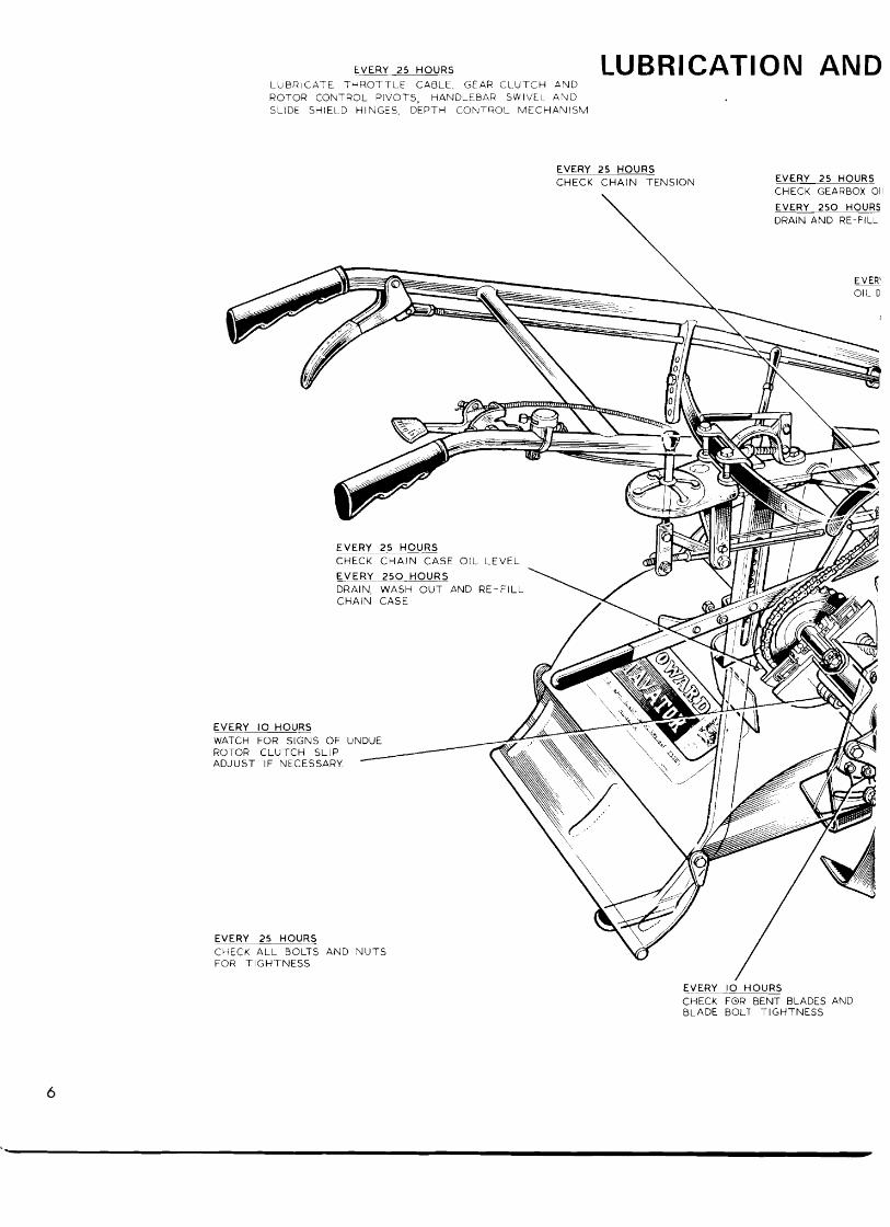
EVERY 25 HOURS L U B R I C A T E T H R O T T L E CABLE. GEAR C L U T C H AND
LUBRICATION AND ROTOR COluTROL PIVOTS, HANDLEBAR SWIVEL A N D SLIDE SHIELD HINGES, DEPTH COhTQOL M E C H A N I S M
EVERY 25 HOURS CHECK C H A I N TENSION EVERY 25 HOURS
CHECK GEARBOX 011
EVERY 2 5 0 HOURS DRAIN AND RE-FILL
EVERY 25 HOURS CHECK C H A I N CASE O I L LEVEL \@I I EVERY 2 5 0 HOURS DRAIN, WASH OUT AND RE-FILL CHAIN CASE
EVERY 10 HOURS WATCH FOR SIGNS OF UNDUE ROTOR CLUTCH SLIP ADJUST IF NECESSARY.
EVERY 25 HOURS CHECK A L L BOLTS AND N U T S FOR TIGHTNESS
EVERY I0 HOURS CHECK FOR BENT BLADES AND BLADE BOLT TIGHTNESS
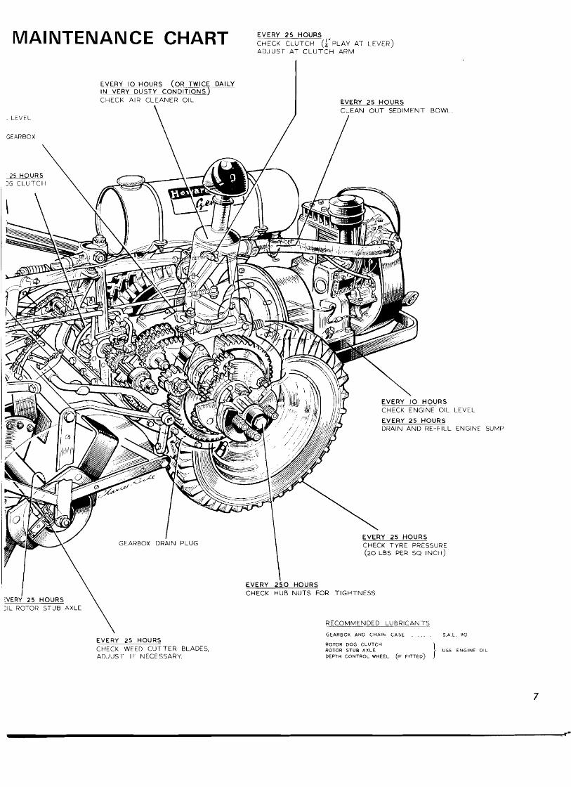
MAINTENANCE CHART : ; :K : : 2CS ibnpLnvAT~~v~~)
. LEVEL
GEARBOX
E!ERY I 0 HOURS (OR TWICE DAILY IN VERY DUSTY CONDITIONS.) CHECK AIR CLEANER O I L EVERY 25 HOURS
C L E A N O U T SEDIMENT BOWL.
LEVEL
ENGINE SUMP
:VERY 25 HOURS I l L ROTOR STUB AXLE \
EVERY 2 5 0 HOURS CHECK HUB NUTS FOR TIGHTNESS
\ RECOMMENDED LUBRICANTS \
EVERY 2 5 HOURS CHECK WEED CUTTER BLADES, ADJUST IF NECESSARY.
GEARBOX AND CHAIh CASE . ... . 5.A E. 9 0
ROTOR DOG CLUTCH ROTOR STUB A X L E ) US. ENGIME OIL DEPTH CONTROL WHEEL (IF FITTED)
ADJUSTMENTS
ROAD WHEELS Each road wheel IS mounted o n its h u b b y a fr ict ion c lutch device. These are adjusted so that the wheels have suff icient gr ip t o pul l the machine, bu t w i l l sl ip if they become jammed w l t h an obstruct ion be tween the wheels and the frame.
For normal adjustment, t ighten each o f the four nu ts t o ful ly compress the springs, then slacken back each nu t half a turn
Should the wheels appear n o t be driving, check that the adjustment is correct.
DRIVE CHAIN Correct drive c h a ~ n tenslon is as Important as correct lubrication. Total u p and d o w n movenlent should be n o more than i n (9.5 n im. ) t o : in. ( 1 2.5 m m . ) Check w l t h a suitahle screwdriver Inserted th rough the o i l filler hole o n the t o p side of the chaincase. Turn the screwdriver t o gr lp the c h a ~ n be tween the links. Loosen the locknut o n the external adiuster o n the bo t t om front of the chaincase, and screw In the adj l~st ln<] screw t o increase chain tenslun Re - t ~gh te r l t 1 - i ~ locknut
CLEANING CHAINCASE After 250 hours of wo rh the ctlalncase should be cleaned ou t Unscrew <]I! the bol ts securlny the chain- case to the bdckplate al lovv~n<l the chalncase o ~ l t o d r a ~ n ou t frorri the jolnt n o drain p lug 1s f i t ted Remove the cover ensuring that the gasket IS no t damaged and wash ou t the lnslde of the case and the chaln w l t h petrol or kerosene Re-assemble, and fill w l t h ,: pint ( 25 Iltre) SAE 90 gear 011
CLEANING GEARBOX The gearbox must also be cleaned ou t after 250 hours work Unscrew the d r a ~ n p lug o n the bo t t om r ight-hand inner side of the gearbox and drain the box immediately after a period of runn lnq The 011 wi l l be w a r m and free- running and any sedlment will be i n suspension in the oi l . Replace the drarn p lug and ref111 the gearbox w i t h about 6 p ints (3.4 l i tres) o f flushing 011 Run the machine for about 3 minutes w l t h the rotor we l l clear of the ground, then drain the f lushing oi l . Refill the gearbox w l t h 6 p ints (3.4 Iitres) o f g o o d qual i ty SAE 90 gear oi l .
ROTOR FRlCTlOlU DRIVE The rotor to which the blades are bol ted is driven direct frorn the main gearbox th rough a fr ict ion c lutch. This c lutch should on ly operate w h e n the rotor blades strike an obstacle, w h e n despatched f rom the factory the
c lu tch is adjusted so that n o sl ip occurs znder normal wo rk i ng condi t ions. I f the c lu tch appears i o slip too easily, i t can b e adjusted b y t ightening the four c lutch nuts t o fu l ly compress the springs. then slackening back each n u t half a turn.
AIR CLEANER The air cleaner o i lbath oi l level must be checked every 10 hours, or every 5 hours In very dusty condit ions. Every 250 hours, the air cleaner lntcrior must be cleaned ou t . U n d o the t w o nuts beh~rlcl the air cleaner, t o separate the air cleaner f r om the support bracket o n the main frame, and u n d o the jutjl lee clip o n the end of the air cleaner hose t o disconnect the cleaner completely. Remove t he black, domed pre-cleaner f rom the t op o f the air cleaner, and f lush ou t the interior o f the air cleaner w i t h paraffin or kerosene, t o remove all dir t and dust frorn the w i re gauze elements inslde.
When clean, refit the pre-cleaner and secure the air cleaner o n the support bracket. Re-connect the hose.
MAINTENANCE OF BLADES Only the cu t t ing edges o f the blades should rub in the so i l : the backs of the blades should be clear
The blades are so deslgnecj that use In average so~ l s should keep them sharp. I f the <]round is very stony however, ~t IS recon~rnended that t w o sets o f hoe blades b e used alternately, so t h a t one set may be kept sharpened
The efficiency o f the machine is determlned largely by the cond i t ion o f the blades. I f they are left bent or dls- Io r ted th rough str lking sol id obstacles i n the ground, they w i l l requlre doub le the power t o drlve. the qual i ty o f t he w o r k w i l l b e poor and the blades will wear much more quick ly . Trouble w ~ l l also arise w i t h c logging under t he shield Blades must therefore b e examined dai ly and any bent ones replaced immediately
ROTOR FLANGE WEEDCUTTERS T w o weedcut ter blades are provided, one at each side o f the machine, t o prevent l ong grass or weeds b inding a round the end rotor flanges. The blades are slotted and secured b y t w o setscrews each, and should b e adjusted so tha t they just clear t he rotor flanges w h e n the rotor is turned BY HAND. Severe power losses w i l l occur in weedy condi t ions unless these blades are correctly adjusted.
ROTORS AND BLADES
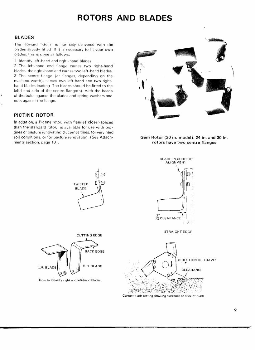
BLADES The Howard "Geri~" is normally delivered with the blades already fitted If it IS necessary to fit your o w n blades, this IS done as follows:
1 . Identify left-hand and r~ght-hand blades. 2. The left-hand end flange carries two right-hand blades. the right-hand end carries two left-hand blades. 3 The centre flange (or flanges, depending on the rnachlne width), carries two left-hand and t w o right- hand blades leading The blades should be fitted to the left-hand side of the centre flange(s), w i th the heads
I of the bolts against the blades and spring washers and nuts against the flange.
PICTINE ROTOR In addit~on, a Pictine rotor, w i th flanges closer-spaced than the standard rotor, IS ava~lable for use wi th pic - tines or pasture renovating (lucerne) tines, for very hard soil condit~ons, or for pasture renovation. (See Attach- ments section, page 10).
TWISTED BLADE
CUTTING EDGE
R.H. BLADE
How to identify right and left-hand blades.
Gem Rotor (20 in. model), 24 in. and 30 in. rotors have t w o centre flanges
BLADE I N CORRECT AL lGNMENl
I I
3" 3-2 CLEARANCE I
L/J
STRAIGHT EDGE
DIRECTION OF TRAVEL
Correct blade setting showing clearance at back of blade.
ATTACHMENTS
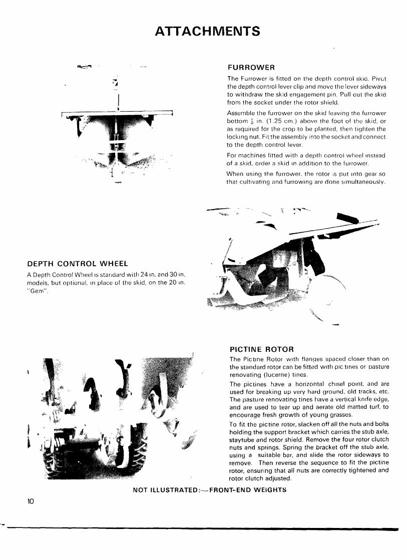
FURROWER
DEPTH CONTROL WHEEL A Depth Control Wheel IS standard with 24 In. and 30 in. models, but optional, In place of the skid, on the 20 In. "Gem".
The Furrower is fitted on the depth control skid. Pivut the depth control lever clip and move the lever sideways to withdraw the skid engagement pin. Pull out the skid from the socket under the rotor shield.
Assemble the furrower on the skid leaving the furrower bottom 4 in. (1.25 cm.) above the foot of the skid, or as required for the crop to be planted, then tighten the locking nut. F i t the assembly into the socltet and connect to the depth control lever.
For machines fitted with a depth control wheel ~nstead of a skid, order a skid I P addition to the Currower.
When using the furrower, the rotor is put Into gear so that cultivating and furrowing are done simultaneously.
PICTINE ROTOR The Pic t~ne Rotor w ~ t h flanges spaced closer than on the standard rotor can be fitted wi th PIC tines or pasture renovating (lucerne) tines.
The pictines have a horizontal ch~sel po~nt , and are used for breaking up very hard ground, old tracks, etc. The pasture renovating tines have a vertical kn~ fe edge, and are used to tear up and aerate old matted turf, to encourage fresh growth of young grasses.
To fit the pictine rotor, slacken off all the nuts and bolts holding the support bracket which carries the stub axle, staytube and rotor shield. Remove the four rotor clutch nuts and springs. Spring the bracket off the stub axle. using a suitable bar, and slide the rotor sideways to remove. Then reverse the sequence to fit the pictine rotor, ensuring that all nuts are correctly tightened and rotor clutch adjusted.
NOT ILLUSTRATED:-FRONT-END WEIGHTS
MAKING THE MOST OF YOUR "GEM"
GENERAL
As the scope of opct 3tion is so wide, and, as soil ti!lage methods differ so gre'itly according to crop, climate and soil condition, it is not possible to deal more than super- ficially with this aspect. However, it is hoped that the following hints will help the user to obtain the best results from the machine.
The Howard "Gem" will cultivate to a maximum depth of 9 in. (23 cm.). On certain, especially the heavier, types of soil, t h ~ s depth will not be obtained in a single pass. Where cultivation in depth is needed, a first pass shouid be made at 3-4 in. (7-10 cm.), followed by a fsrther pass at full depth.
The low gear must be used when cultivating ground which is very hard or covered with heavy growths. Second gear is used for all ordinary cultivation, and top gear for light cultivation. Always work ~n the highest gear that will produce the quality of tilth necessary. Always use top gear for running the machine between jobs. A depth control skid or a wheel, is fitted, and by moving this up and uown the depth of work can be controiled in 2 in. (19 mm.) stages down to 9 in. (23 cm.) deep.
If the surface of the ground is very hard or baked, the depth control should be adjusted so that the machine just bites the surface. Further passes should then be made until the required depth is reached.
On heavy land which is to be laid up for the winter, the surface should be left rough. By using the ridging or furrowing attachment during this final or late autumn cultivation, the land can be left in ridges to promote better drainage and to expose a greater surface area to the weather.
If heavy land IS Rotavated too finely and left bare to the winter rains, the soil may pack together, making spring cultivations difficult.
When cultivating a ploughed field, the "Gem" should be run across the furrows, not along them. This will ensure complete cultivation.
On hilly ground always run the machine around the contour, working from the top to the bottom of the hill. After the first cut, one road wheel can be run in the soil just worked, so that any tendency to slip will be countered by the wheel coming against a wall of uncut soil.
On light soils, two courses are open. The ground may either be left rough, or it may be Rotavated to medium depth and sown to a green crop, e.g. rye. The green crop will prevent the leaching out of the nitrogen in the
soil. In the early part of the year the crop is then Rotavated. After a week or ten days, the spring seed bed may be prepared. This Rotavation should be shallower than that used to work-in the green crop.
SEED BEDS In ground which has been cultivated properly, seed beds should seldom exceed 2 in. (5 cm.) in depth, except for certain crops. Seeds require a well-aerated soil with a firm bottom. Some small seeds require a seed bed to be lightly consolidated. This is particularly important on light soil, where consolidation will bring moisture nearer to the seedling plant.
Competition from weeds is most critical when the crop is at the seedling stage. To obtain weed-free seed beds, the ground should be prepared a few weeks ahead of the sowing dates. Rotavation should be carried out at a depth of 4 In. (1 0 cm.); this causes any weed seeds to germinate. These weeds may be turned in by a second Rotavation, which will prepare the seed bed at the same time. It is most important that this second Rotavation is shallower than the first. Remember that the ground is now more open, so that the machine will tend to dig more deeply. When the seed bed has been prepared, it should ideally be allowed to settle for 24 hours before sowing.
WEED CON-TROL Rotavation produces a well-aerated warm seed bed in which germination takes place readily. Inevitably, such conditions also favour weed seeds.
Weeds are eliminated by preventing them seeding or by progressive weakening of the deep tap roots or rhizomes. Weeds are killed most easily and inexpensively by Rotavating them directly they show green. Annuals will be killed outright and perennials will be reduced until they too, die out. This is true even of such persistent weeds as couch or twitch.
ROW-CROP WORK Work will be easier if rows are made as long as possible. At least 3 ft. (1 m.) should be allowed at each end for turning.
Weeds between rows may be controlled by Rotavation. Ideally, this should be done when the weeds are small, but even a heavy growth can be turned in.
This will not prevent weeds growing in the rows them- selves; such weeds must be controlled by hand-hoeing when small. Should land become weed-infested because these weeds have been allowed to seed, the

following crop should be a cleaning crop, e.g. roots or potatoes, which will give a period of several weeks in the early part of the year when the weed seeds wil l shoot and can be killed by Rotavation.
In planning your crops to make the best use of the "Gem", allow 2 or 3 in. (5 or 7 cm.) over the effective width on each side of the machine.
GREEN MANURING Land not immed~ately required may be sown down to such crops as mustard or rye grass during spring and summer, or rye during the winter. These crops should be allowed to mature if they are to be used as green manures - they wil l then have the best effect on the soil. A winter cover crop wil l preserve plant foods which
would otherwise be leached away, so it need not be allowed to mature.
LAND RECLAMATION The "Gem" may also be used to bring derelict land back into cultivation. Virgin ground or soil tightly bound with roots or grass is best cultivated by fjrst working at only a shallow depth, to break up the surface. Depth can then be gradually increased by subsequent passes made at intervals of about a week or ten days.
CONCLUSION Never overtax the power of the machine. Far better results will be obtained from working in easy stages, rather than by forcing the machine to do work in excess of its horsepower.
The right to alter and/or amend all designs, specifications and/or prices without prior notice is strictly reserved.

Howard Rotavator r - *' P<-Y,-:?7 a
A member of the How
Telephone Bury St E-ds (0284 ) 6326