
STUDIES ON THE DEVELOPMENT OF THE ROTAVATOR CUM …ejtafs.mardi.gov.my/jtafs/08-2/STUDIES.pdf ·...
14
MARDI Res. Bull..8. 2 : (209-2221 STUDIESON THE DEVELOPMENT OF THE ROTAVATOR CUM RIDGER OOI HO SENG+ Keywords: Tobacco ridge formation, Rotavator Cum ridger. RINGKASAN Satu kajian telah dijalankan mengenai kesesuaian pembajak berputar (rotary cultivator) yang di sambungi dengan pembatas (ridger) untuk digunakan di atas tanah lekit (cohesive soil). Analisa tentang tarikan (draught iorce), hasil dari penggunaan pembajak berputar itu telah dibuat. Ini bertujuan untuk mendapatkan keterangan dan kefahaman lengkap tentang reka-bentuk dan pembinaan alat penyambung antara pembatas (ridger) dan pembajak berputar. Dari ujian yang ddalankan didapati bahawa penggunaan mesin pembajak-pembatas (rotavator cum ridger) itu adalah memuaskan. INTRODUCTION Tobacco is often grown as the off season crop in the paddy fields in Kelantan. Among the problems encountered in tobacco growing is the formation of ridges during the land preparation phase. The soil condition neededfor tobacco growing is open textured with good drainage (AKEHURST. 1913). Tobaccowilts very quickly under conditions of sudden flooding. To have open texture, the soil has to be fairiy well broken down so that there are no large clods and it should have a considerable depth of tilth. All these conditions can be satisfiedby the combination of appropriate land preparation and the planting of tobacco on ridges. Ridge planting is practised by the farmers in Kelantan. At present, the farmers hire contractors to disc-plough their fields (with four wheel tractors) and then to rotovate them (with either four-wheel or two wheel tractors). The ridges can be made either manually by the farmers themselves and the hired workers using hoes or mechanicallyusing ridger bodies (body) pulled by tractor (pedestrian tractor). At presenta substantial amount of manhours are being spent by the farmerson the ridging operation.The objectiveof the present work is to transfer the long and tedious work of ridge formation from the farmers, who do it manually, to the contractors presumabiy at reduced cost as the ridging operation could possiblybe done at the same time as the rotovating operation. As mentioned above. the tobacco is grownasoff-season crop on the paddy land where the soil is mostly of the cohesive type (clayeysoils). Generally, draughl implements (like the ridger) perform badly on cohesive soils while they work well on light soils. Therefore in the present study, the work would be concentrated on ridge formation on cohesive type of soii. PROCEDUREAND SCOPEOF STUDY A comprehensive study was made of reievant works related to the theory and practical applicationof rotary cultivatorsand draught implements. To gain more practical experiince, variousfield tests were carried out using appropriate rotary cultivatorsand ridging implements on four-wheel and two-wheeltractors.From literaturereviewand practical experience obtained, i Agriculture Engineering Branch, MARDI, Serdang, Selangor.
Transcript of STUDIES ON THE DEVELOPMENT OF THE ROTAVATOR CUM …ejtafs.mardi.gov.my/jtafs/08-2/STUDIES.pdf ·...

MARDI Res. Bul l . .8. 2 : (209-2221
STUDIES ON THE DEVELOPMENT OF THE ROTAVATOR CUM RIDGER
OOI HO SENG+
Keywords: Tobacco ridge formation, Rotavator Cum ridger.
RINGKASAN
Satu kajian telah dijalankan mengenai kesesuaian pembajak berputar (rotary cultivator) yang
di sambungi dengan pembatas (ridger) untuk digunakan di atas tanah lekit (cohesive soil). Analisa
tentang tarikan (draught iorce), hasil dari penggunaan pembajak berputar itu telah dibuat. Inibertujuan untuk mendapatkan keterangan dan kefahaman lengkap tentang reka-bentuk danpembinaan alat penyambung antara pembatas (ridger) dan pembajak berputar. Dari ujian yang
ddalankan didapati bahawa penggunaan mesin pembajak-pembatas (rotavator cum ridger) ituadalah memuaskan.
INTRODUCTION
Tobacco is often grown as the off season crop in the paddy fields in Kelantan. Amongthe problems encountered in tobacco growing is the formation of ridges during the landpreparation phase. The soil condition needed for tobacco growing is open textured with gooddrainage (AKEHURST. 1913). Tobacco wilts very quickly under conditions of sudden flooding.To have open texture, the soil has to be fairiy well broken down so that there are no largeclods and it should have a considerable depth of tilth. All these conditions can be satisfied bythe combination of appropriate land preparation and the planting of tobacco on ridges. Ridgeplanting is practised by the farmers in Kelantan. At present, the farmers hire contractors todisc-plough their fields (with four wheel tractors) and then to rotovate them (with eitherfour-wheel or two wheel tractors). The ridges can be made either manually by the farmersthemselves and the hired workers using hoes or mechanically using ridger bodies (body) pulledby tractor (pedestrian tractor). At present a substantial amount of manhours are being spentby the farmers on the ridging operation. The objective of the present work is to transfer thelong and tedious work of ridge formation from the farmers, who do it manually, to thecontractors presumabiy at reduced cost as the ridging operation could possibly be done at the
same time as the rotovating operation. As mentioned above. the tobacco is grown as off-season cropon the paddy land where the soil is mostly of the cohesive type (clayey soils). Generally, draughl
implements (like the ridger) perform badly on cohesive soils while they work well on light soils.
Therefore in the present study, the work would be concentrated on ridge formation on cohesivetype of soii.
PROCEDURE AND SCOPE OF STUDY
A comprehensive study was made of reievant works related to the theory and practicalapplication of rotary cultivators and draught implements. To gain more practical experiince,various field tests were carried out using appropriate rotary cultivators and ridging implementson four-wheel and two-wheel tractors. From literature review and practical experience obtained,
i Agriculture Engineering Branch, MARDI, Serdang, Selangor.

i t was considered that the total energy required in tobacco land preparation could be minimisedby combining some of cultivation operations involved. An investigation was made to examinethe suitabil ity of combining the rotavator and tl.re ridging implement for tobacco ridgeformation. The objecitve was to make use of the forward thrust of the rotavator to providesome of the draught force required by the ridging implement. An analysis of the draught forcedeveioped by the rotavator was attempted using basic soil dynamic theories proposed byHrrr lenRrcHt et . a l . , (1966) and KosrRIrsyN (1956). The other par t of the studyinvolved the design and construction of the attachment assembly for the ridger bodies to bemounted behind the rotavator and the field-testing of the machine to evaluate its performance.
ANALYSIS OF ROTOVATOR DRAUGHT FORCE
The rotary cultivator derives most of the power required from the p.t.o. Its rotaryaction also provides a driving force that assists forward traction without exerting downwardpressure. The L-shaped rotavator blade may be divided into its two components, the shank andthe horizontal 1imb, to simplify the problem in the calculation of the draught forces developed(CHeueN. 1914). An estimation of the forward thrust developed by the horizontal portion canbe made based on the theory proposed by HErrtanATCHI et. ul., (1966). The soil force, Pper unit width of blade span is given by the equation
t = t:r-^l'I *l t:
' w z ' N , 1 6 z N s * c u z N u + q z N q . . . . . . . . . . . . . . . . . . . ( 1 )
where P*, P. ,Pu,and Po are the components of P due to soi l bu lk densi ty w, cohesion c.adhesion
!u,u ld surcharge q respect ive ly : and N*,N. ,Nu and NO are d imensioniess Reece
Numbers (see ,FrSf. 1).
Neglecting the effects due to surcharge and adhesion as they are comparativell, small in acohesive soil, the above equation becomes.
P = * 2 2 N * * . , N c . . . . . . . . . . . . . . . . . . . . . . . . . . . . . . . . . . . . . ( 2 )
The range of rake angle at interface (o). for which the above equation is valid varies from 45degrees rninus @/2 to 180 degrees minus @, where @ is the internal angle of friction. Table 3 showsthe caiculated single blade soil forces using the measured soil physical properties gven in TableI (see Plate-3) and the blade physical dimensions given in Table 2.
There is an additional force per unit width, R,. acting aiong the face of the blade, i.e.
Ru = cuz Cosec c< . (3)
The blade normal and tangential forces Fn and F, respectively are than given by,
Fn = sP Cos 6 . . . . . . . . . . . . . . . . . . . ( 4 )
F, = sP Sin 6 + scu z Cosec .... . (5)
where s is the span of the blade and 6 is the soil-metal friction angle. The draught forcedeveloped by the horizontal l imb of the blade FO6, may then be obtained from the equation,
F d h = F n C o s ( d + 7 . 1 8 0 ) + F t S i n ( 0 + 7 . 1 8 0 ) . . . . . . . . . . . . . . . . . . . ( 6 )
where 0 is the angle of rotation with respect to the top verticai radius and 7 is the blademounting an$e (See Fig. I and Table 4). The variation of the calculated drausht force with theangle of rotation is illustrated tn Fig. 2.
210

fiI,
IIt.t '
! lt!
I,t,
v
v- 2 -\
,r;t A
,
6I
IIIl _ _
Figure 1. Soil failure due to horizontal limb of blade
Having found the variation of draught forces with angle of rotation, it remains to predictat which point of the cutting cycle that shearing of the soil takes place. From fieldobservations, it appears most l ikely to occur at angle of rotation 0. equals 180 degrees.
TABLE I . MEASURED SOIL PHYSICAL PROPERTIES
MoistureContent(drv)
%
BulkDensity
(w, dry)kgf/nr
Adhesion(ca)
kgf lm2
Cohesion(c)
.,'Kg I / I n -
SoilFriction
(0)deg.
Soil-MetalFriction
(6 )deg.
20.5 r00
211
900 25.5 1 9 . 0

g
ctl
:
\tLL
oC'
o))(!
U
0120 160 t80 200 220
A n g t e o f R o t a t i o n 0 ( d e g )
Figure 2 Calculated draught forces developed by horizontal timb of blade
Tlie blades in the rotavator are nrounted in a spiral forrnation such that the cut on thesoil is rnade one blade at a time. Therelbre the eff-ective draught force developed b1, the bladesmay be considered as uniform. The resultant draught force developed by the horizontal l irnbsof the rotavator blades D1.,, rnay be obtained frorn the equation,
D h = F d h u n ( 9 r - 0 t ) . . . . . . . . . . . . . . . . . . . . . . . . . . . . . ( 7 )
, *
TABLE 2. ROTAVATOR BLADE PHYSICAL DIMENSIONS
BladeSpan(s )nt
BladeChord
m
Blade TipRadius
(r.lln
BladeMount ingAngle (7)
deg .
BladeShank
IN
OverallCuttingwidth
m
Number ofBlades
(n)
0 . 1 2 0.084 0.28
212
60 0 . r 4 l .543 6

where F66u is the average draught force developed by the horizontal l imb of a single blade forangle of rotation frorn d1 to d, during whicl-r the blade exerts a forward thrust against the soiland n is the total number of blades. Frorn Flg 2,Fdlru was estimated to be 14.1 kgf. Thusthe resultant draught force'developed by the horizontal portions of the rotavator blades is
D n = 1 + . t x 3 6 ( 1 8 0 - 1 2 9 )
360
= jll_g!
It should be pointed out that the actual failure pattern in the soil is quite complicated due tothe curved path of the blade and not as simple as shown in Fig. 1. Furthermore, Reece'sequation (i.e. Eqn. l) applies to all forms of soil failure where deformation takes place slowly,so that inertia forces due to velocity effects can be neglected. The application of the above theorywill therefore inevitably involved large errors, Nevertheless the analysis is useful for a betterunderstanding of the important factors governing draught forces developed by the rotavatorb lades.
The draught force on the shank of the blade may be analysed based on the theoryproposed by KOSTRITSvN (1956). Referring to Fig. 3, the soil force F, is given by
where
F = N r S i n B + N 1 B C o s p + ( N 2 + N 3 ) 8 ( 8 )
B = wedge angle of cutter = 9o
B = Tan 6 = coefficient of soil-metal sliding fricl ionN, = Normal force on the wedge of cut ter
N:, N: = Norrlal forces on the slides of cutter
The norrnai forces N1,N: ,N: are due to the res is tance of so i l to deformat ion, i . : .
N l = K l A l . . . . . . . . . . . . . . . . . . ( 9 )
N 2 = K 2 , A 2 . . . . . . . . . . . . . . . . ( 1 0 )\ t' " 3 -
K 2 A 3 . . . . . . . . . . . . . . . . ( 1 1 )
where A1, A1. 43, are the respect ive areas of t l ie s ides of the cut ter in contact wi t l i the soi l ,K1 is the soil specific resistance to elastic and plastic deformation. and K. is the soil specificresistance to elastic deforrnation onlv. Thus
-6=
NJ
Figure 3. Section through the shank of blade
Nt
a t 1

TABLE 3. CALCULATED SINGLE BLADE SOIL FORCES (HORIZONTAL LIMB)
Angle ofRotat ion
(0 )deg.
Rake Angle(aldeg.
Depth of Cut(z)n 1
Reece Numbers
N
Soil Force(P)
kgl/rn
r26t J t
136t4 ll 5 l1 6 6179
831 8/ )od
5 8A 1+ J
3 0
2 . 11 . 91 . 87 al - l
1 . 61 . 51 . 6
4 .94.43 . 8J . O
a 1J . l
2 . 31 . .9
00.00650.0240.04r0.0660.05 70.042
02 5 . 882.6
r 3s .5178.71 1 7 . 374.4
TABLE 4. CALCULATED DRAUGHT FORCES DEVELOPEDBY BLADE (HORIZONTAL LIMB)
Angle ofRotation
(0)deg.
( 0 + q - 1 8 0 )deg.
Soil Force(P)
kgf/m
TangentialForce(Ft)kgf
DraughtForce(Fan)
kgf
NormalForce(Fn)kgf
r261 3 i1 3 6l + l
t 5 lr66179
02 s . 882.6
l J ) . )
118.7t17 .374.4
02.99 .4
r5 .420.3I J . J
8.4
0l IJ . )
5 . 81 . 95 . 63 . 9
0J . t
1 0 . 01 0 . )
t l . )
l J . l
1 . 7
6l lt 62 1J . t
465 9
K t =
K z =
K ^ tt r l
K^rg l
* K ^ l . . . . . . . . . . . . . . . ( 1 2 )Y '
. . ( 1 3 )
+ 5.4 kgf lcm2
kgf lcm2
kef lc^2
The values of soil specific resistances to elastic and plastic deformation obtained by Kostritsynexperimentally were 0.390 kgf/cm2 and 5.4 kgf lcm2 respectively, Using these values,
Kt = o'390= ) . t Y
K2 = o'390
Substituting in Equations 8 to I 1, the values of F for different angle of rotation d may beobtained. The draught force developed, F6r, is given by
F d , = F C o s ( 1 8 0 - 0 + e ) . . . . . . . . . . . . . . . . ( 1 4 )
where e (= 35 deg.) is angle made by the cutting edge of shank with the radius of rotation.Table 5 shows the calculated draught force developed by the shank for various angle ofrotat ion A.
214

TABLE 5. CALCULATED DRAUGHT FORCE DEVELOPED BY SHANK BLADE
Angle ofRotation
d.g.
( 1 8 0 - e )deg.
SoilForce
F
kgf
DraughtForceFd,
kgf
Ar A2cm2 cm2
A3
cm2
1 3 0140l 5 u
1 6 0r 8 0200210220230
857 5655 5J )
l 55
-15
U
t 6 . 226.428.626.61 9 . 813.26 .3
0
0I 6J 6 . )
57.869.858.242.624.50
n
012.429.64 J . )
38 .6zv - J
1 8 . 30
049.183.494.792.370.441 .924.00
0t 2 . 735.254.37 5 .668.04'7 .723.90
The average draught force developed by the shank of a single blade may be obtained byplotting the curve of FO, against angle of rotation 0 as shown in Fig. 4. Assuming thedraught force developed by the blades of the rotavator is uniform, then the resultant draughtforce developed by the shanks D", is given by
360
where F6ru is the average draught force developed by. the shank of a single blade for angle ofrotation from 0r to dr. From Fis. 4, F6ru was estimated to be 48.10 kgf. Thus the resultantdraught force developed by the shanks of the blades is
D, = 48.10 x 36 x !1S-:l-9. kef360
= 39-Sl
From field observations, it was found that the cut soil was being thrown upwards(almost vertically) by the rotavator blade as it left the ground. Therefore the effect of soilinertia on the draught forces developed is quite small. Neglecting draught forces due to inertiaon the draught forces developed is quite small. Neglecting draught forces due to inertia of cutsoil, the total resultant rotavator draught force D, is given by
Dt = Dh * D, . . . . . . . . . . . . . . . . . . . . . ( i6 )= 71.9 + 202.0 kgf .= 273.9 kgf .
The main objectives of the above analysis were to obtain an indication of the magnitudeof the draught forces developed by the rotavator as well as an indication of the importantfactors governing draught and power requirement. From the analysis above, it was apparent that
zt5

F .05a
;
3l/l
!
TL
q)!)
b
Ido
170 190 210Angte o f Rota t ion 0 ( deg )
Figure 4. Calculated draught force developed bt, shank of blade
216

ROTOVATORSOIL COVER
R U 8 B E RF L A E
)oo, cARRTER
A T T A C H M E N TB R A C K E T
Figure 5. Exploded perspectiveattachment assembll,
vielv of r()tovator cum ridger showing detait of
2t7

the soil condition was a major governing factor. Field measurements had shown that the soilphysical properties varied with the moisture content. Thus it is irnportant that the soil physicalproperties be measured during experimental runs on sunny days when soil moisture content canvary greatly during the day.
EXPERIMENTSA series of experiments were carried out on 40 meter by 20 rneter plots at various sites
to evaluate the performance of the machine which consisted of a standard Howard Rotavatorand the specially designed attachrnent assembly for ridger bodies to be mounted behind therotavator (see Flg. 5 and Plates 1,2). A FIAT 540 traetor was used in the trials. At each sitesimilar treatments were conducted (see Tabte 7). They consisted of:-
(A) plough, rotavate once, and then fonn ridges (l ridge per pass)(B) plough, then use the rotavator cum ridger (1 ridge per pass)(C) plough, rotavate once, then use the rotavator cum ridger (1 ridge per pass)(D) plough, rotavate twice, then form ridges (2 ridges per pass)(E) plough, rotavate once, then use the rotavator cum ridger (2 ridges per pass)
In treatments B and C, one of the ridger bodies was mounted in line with the right rearwheel of the tractor (see Plate ./) so that the wheel of the tractor ran along the furrow of thepreceeding run. Only one ridge was formed per pass as the ridger body on the right side merelyrepaired the damage done by the right, front and rear wheels of the tractor to the furrow ofthe preceeding run. In treatment E, a marker was used as shown in Plste 2. Two ridges weremade per pass. However the surface tilths on the ridges were not similar between adjacent rowsas the soil forming rows 1,3, 5, etc. were rotavated only once. This was because the workingwidth of the rotavator was 60 inches (154 cm) while the spacing between furrow was 36 inches(91.4 cm).
. f
Plate l. Shows tlte use of the rotavator cum ridger for making riclges (l ridge per pass) on apreviously ploughed land. Note that the right ridger body is in line with the right rearwheel of the tractor.
218

Plate 2. Shows the use of the rotavator cum ridger with spacing marker on previouslyrotavated lttnd.
The main purpose of the experiments was to determine the effectiveness of the rotavatorcurn ridger in increasing the work rate in tobacco land preparation while maintaining thepower requirement (i.e. allowing the same tractor to be used). Soil density, friction angle andcohesion were measured immediately after each operation and moisture samples were takenduring the runs (see Plate 3/. For the present discussion, the results of experiments at only onesite are considered here. The deductions and conclusion made from these experiments arerepresentative of all the other experiments on cohesive type of soil.
RESULTS AND DISCUSSION
Table 6 shows the soil condition measured after each cultivation. There was nosignificant difference in the values of the soil properties obtained between the rotavatingoperation (Ro) and the rotavating cum ridging operation (RR). In treatment E the soil formingthe middle portions of rows 2, 4, 6, etc. had soil condition II while the rest of the area hadsoil condition III as the former had been rotavated only once.
Table 7 shows the difference in the total time taken in the cultivation of the land andthe formation of ridges between different treatments. It was noted that the total t ime takenwas dependent on the total number of passes and the number of ridges formed per pass.Con-rparing treatrnents A and B which gave the same soil condition II (see Tabtes 7 ind.6), there was a significant decrease in the total time required when the two operations ofrotavation (Ro) and ridge formation (Ri) were combined into one pass with the use of therotavator cum ridger (RR). A similar increase in work rate was recorded in treatments C and Eover treatment D. It should be pointed out that the values given were extrapolated l inearlyfronr results obtained on 40 meter by 20 meter plot.
219

Plate 3. Shows ilte measurement of soil physical properties using the SR-2 Soit ResistanceTester.
TABLE 6. SOIL CONDITION AFTER EACH CULTIVATION
Soil ConditionAfter Operation
Bulk Density Moisture Contentdry, kgf/mr dry,%
Cohesionkgflm2
Soil Soil-metalFriction Friction
I. PIII. Pl + Ro
P I + R RIII. Pl + Ro (2)
P l + R o + R R
20.5
20.29 1 0
20.2
1300
900
800
l7.oo 2090
20.40 2030
23.50 19.00
TABLE 7. TOTAL TIME TAKEN FOR RIDGE PREPARATION
TreatmentsNo. ofPasses
Time (hrs/ha) for each operation Total Time(hrs/ha)RR
(A) Pl+ Ro { Ri (l ridge)(B) Pl + RR (l ridge)(C) Pl + Ro + RR (l ridge)(D) Pl + Ro (2) + Ri (2 ridges)(E) Pl + Ro * RR (2 ridges)
2J
4J
4.s4.54.54.54.5
4.0 3 . 5
2.0
r2 .o9.0
t2.o14.010.5
4.0t . )
4.0
4.53 .5
2.0
220
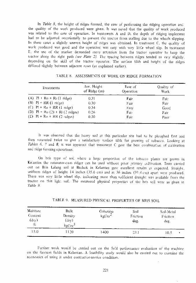
ln Table 8, the height of ridges formed, the ease of perforrning the ridging operation andthe quality of the work produced were given. It was noted that the quality of work producedwas related to the ease of operation. In treatments A and D, the depth of ridging iniplementhad to be adjusted occasionally to prevent the tractor from stail ing due to the wheels slipprng.In these cases a slightly uneven height of ridges was obtained. In treatrnent C, the quality ofwork produced was good and the operation was easy with very 1itt1e rvheel slip. In treatmentE, the use of the marker demanded more attention from the tractor operator to keep thetractor along the right path (see Plate 2). The spacing between ridges tended to vary slightly,depending on the skil l of the tractor operator. The surface ti l th and height of the ridgesdiffered slightly between adjacent rows (as explained earlier).
TABLE 8. ASSESSMENTS OF WORK ON RIDGE FORMATION
Treatments Ave. Heightof Ridge (m)
Ease ofOperation
Quality ofWork
( A )
(B)(c)(D)rF)
Pl +Pl +P l +P l +P l +
0 . 3 10.300.340.260.30
FairFai rEasyFairFair
FairFairGoodFairPoor
Ro + Bi (1 ridge)RR (1 r idge)Ro + RR (1 ridge)Ro (2) + Ri (2 ridges)Ro + RR (2 ridges)
It was observed that t l ie heavy soii at this particular site had to be ploughed first andthen rotavated twice to give a satisfactory surface ti l th for growing of tobacco. Looking atTablcs 6, 7 and 8" it was apparent that treatrnent C gave the best corlbination of cultivationand ridge forrning operations.
On bris type of soil rvherc a large proportion of the tobacco plants are grown inKelantan the rotavator-cuu ridger can be used without prior primarl, culti i ,ation. Tests carriedout on Bris Lalang soil at Bachok in Kelantan gave excellent results as expected. Straight.uni fornt r idges of height 14 inches (35.6 cm) ancl at 36 inches (91.4 cnr) apar t were produced.There was very l itt le wheel slip, indicating more than sufficient draught was available fror.1 thetractor on this l ight soil. The measured physical properties of the bris soil were as given inTable 9.
TABLE 9. MEASURED PHYSICAL PROPERTIES OF BRIS SOIL
MclistureContent(drv)
%
BulkDensity(dry)
kgf/m3
Cohesion)
KgI /m-
SoilFr ic t ion
deg.
Soi l -Meta1Fr lc t ion
deg.
1 5 . 0 l 1 2 0 r 400 2 3 . 1 r 0.5
Further work would be carried out on the fie1d performance evaluation of the rnachineon the farmers fields in Kelantan. A feasibil i ty study would also be carried out to examine theeconomics of using it under contractor-service condition.
221

CONCLUSION
Following the discussion above it can be conciuded that the rotavator curn ridger wasvery effective in reducing the total energy required to produce the desired ti l th and soilcondition for tobacco growing. Furthermore the ridges forrned were more uniform in height andspacing than that obtained frorn the other methods.
ACKNOWLEDGEMENTS
The author would l ike to express his appreciation and gratitude to Err. Yahaya Hj. AbdulHamid, a Research Assistant and En. Mohd Nor Yahaya, a welder. for their assistance in thefabrication work and in conducting the experiments. Thanks are also due to En. Mohd DaharnDaud and his supporting staff (stationed at Kubang Keranji) for their cooperation andassistance.
SUMMARY
An invest igat ion was carr ied out to examine the sui tabi l i ty of combining the rotarycultivator and the ridging implement for use on cohesive type of soil. An analysis of the draughtforce developed by the rotavator was at tempted to obtain a bet ter understanding of the factorsinvolved in the design and construction of the attachment assernbly for the ridger bodies to bemounted behind the rotavator . Frorn the tests carr ied out i t was tbund that the rotavator cumridger rvas very effective in reducing the total energy required in tobacco land preparation andin improving the rvork performance.
REFERENCES
AKEHURST, 8.C. , (1973). Tobacco Tropical Agr icu l ture Ser ies, Longman.
CHAMEN, W.C.T. . and OFIELD, R.J. (1974). Studies to Invest igate the Design of a RotaryDgging Machine i97i 1973 Investigations . NIAE Departmental Note DNlTCl371l1260
GEr-Clouct{ , D. and CHANCELLoR, W. (1976). Pul l and L i l t Character is t ics of Single Lugson Rigid Wreels in Wet Rice Soil . Trans. A.S.A. E. 19 (3); 433.
GILL, W.R. and VANDEN BERG, G.E. (1968). Soi l Dynarnics in T i l lage and Tract ion.Agr ic .Handbook No. 316, Agr . Res. Serv ice. U.S. Dept . of Agr ic .
H A R R A L , B . B . ( 1 9 7 4 ) .DN 'Cu /543 / I 260 .
An Analysis of Cultivation Techniques , N.l.A.E. Departmental Note
Hnr r raRRrcHr . D .R .P . , w r rN r . v , B .D . and RF ILCL , A .R . (1966 ) . The Ca lcu la t i on o fPassive Pressure in Two-Dnrensional Soil Failure , J. Agric. Eng. Res., lI (2): 89.
KoSTRITSYN, A.K. (1956). Cut t ing of a Cohesive Medium wi th Knives and conesVsesoiuzz Akad. Sel skokhoziaistvennykh Nank. Zeml. Sborn. Truclov. (Leningrad) 3.241(NIAE Trans No. 58) .
Sot ,HNl , W. and EGGI ' INNI[ rLLrrR, A (1959). High-spced Rotary Cul t ivators low speed rotaryspades. Invest igat ion wi th indiv idual tools . Grundl . Landtech. (11) .72 (NIAE Trans. No.I I ) .
222