Home automation and security system with the Raspberry Pi
60
Home automation and security system with the Raspberry Pi Ashkan Yaldaie Bachelor Thesis HAAGA-HELIA University of Applied Sciences 17 March 2016
-
Upload
hoangkhanh -
Category
Documents
-
view
224 -
download
0
Transcript of Home automation and security system with the Raspberry Pi

Home automation and security system with the Raspberry Pi
Ashkan Yaldaie
Bachelor Thesis
HAAGA-HELIA University of Applied Sciences
17 March 2016
Abstract
17 March 2016
Author(s) Ashkan Yaldaie
Degree programme Business Information Technology
Report/thesis title Home automation and security system with the Raspberry Pi
Number of pages and appendix pages 49 + 6
There are home automation products available off-the-shelf. The problem is that they are quite expensive and sometimes do not offer a solution to some personal needs. One of the alternatives is to create the product and not to purchase one. The current paper is a bachelor thesis which examines the possibility of developing a home automation and security system by using the Raspberry Pi. The paper covers the theoretical background, planning, imple-mentation, testing and evaluation phases of the project. The thesis work duration was from October 2015 until March 2016. The content of the paper demonstrates that creation of such a product is possible by explain-ing how to connect external sensors and devices to the Raspberry Pi. The product can be controlled locally and remotely through a graphical user interface, nevertheless, a complete tutorial on the programming is out of the scope. The paper also presents some pictures and diagrams in order to make the work more understandable. The chapter "Background" contains some information about the software and the hardware which are utilized for this thesis paper and the Raspberry Pi is used as the main development board based on its abilities and features. The Raspberry Pi fulfilled its purpose for this pro-ject. All the thesis objectives were met and the questions were answered but there is always a room for improvement in the future implementations and the chapter called "Ways to im-prove future implementations" is dedicated to the further development of the current product.
Keywords raspberry pi, home automation, security system, smart home, python, bash
Table of contents
1 Introduction ............................................................................................................................. 1
1.1 Project questions and objectives ................................................................................... 2
1.2 Project's purpose and scope ......................................................................................... 2
1.3 Methodology .................................................................................................................. 3
2 Background ............................................................................................................................. 4
2.1 Choosing the development board .................................................................................. 4
2.2 Home automation and security system ......................................................................... 8
3 Planning ................................................................................................................................ 11
3.1 List of required sensors and devices ........................................................................... 13
4 Implementation of a home automation and security system ................................................ 16
4.1 Setting up the Raspberry Pi ......................................................................................... 16
4.2 Home automation ......................................................................................................... 18
4.2.1 WIFI sockets .................................................................................................... 19
4.2.2 Radio frequency sockets .................................................................................. 20
4.2.3 Controlling the sockets using home temperature and timer ............................ 21
4.2.4 Voice control .................................................................................................... 24
4.3 Security system ............................................................................................................ 26
4.3.1 Creating a wireless motion sensor ................................................................... 26
4.3.2 Sending an SMS and triggering the alarm if motion is detected ..................... 28
4.3.3 Implementation of a panic button ..................................................................... 30
4.3.4 Connecting a camera to the system to capture a video clip of an intrusion .... 31
4.3.5 Uploading the video to the cloud and sending an email notification ............... 33
4.3.6 Controlling the security system via Bluetooth .................................................. 34
4.4 Creating a graphical user interface for the system ...................................................... 36
5 Testing .................................................................................................................................. 41
6 Ways to improve future implementations ............................................................................. 44
7 Conclusion ............................................................................................................................ 46
References................................................................................................................................. 47
Appendices ................................................................................................................................ 50
Appendix 1. Devices used for this project and the purchase information ............................ 50
Appendix 2. Table of GPIO pins and their numbers (wiringPi, BCM, GPIO and physical pin
numbers) ............................................................................................................................... 51
Appendix 3. The bash script used to control the sockets ..................................................... 52
Appendix 4. The final version of motion.py .......................................................................... 53
Appendix 5. Pictures of the GUI ........................................................................................... 54
Appendix 6. Pictures of the device ....................................................................................... 55
Figures and Tables
Figure 1 The Raspberry Pi and its connectors
Figure 2 An example of a floor plan that shows the position of the security devices
Figure 3 Items used to create a wireless motion sensor
Figure 4 Devices used for creating the smart home functionality
Figure 5 Output of the df -h command
Figure 6 Output of the nmap command
Figure 7 Communication with the WIFI socket
Figure 8 433MHz RF transmitter and receiver's connection to the RasPi
Figure 9 Wiring diagram for the temperature sensor
Figure 10 Reading the room temperature
Figure 11 Wiring diagram for the wireless motion detector's transmitter
Figure 12 Wiring diagram for the wireless motion detector's receiver
Figure 13 Connection to the 3G modem
Figure 14 Wiring diagram for the panic button
Figure 15 IP camera RTSP address
Figure 16 Devices which can be used to control a security system
Figure 17 Bluetooth's battery use
Figure 18 RasPi's IP address
Figure 19 PIR sensor
Figure 20 Extra sensors to improve the product
Table 1 Raspberry Pi 2 vs Beaglebone hardware chart
Table 2 Example of a crontab command
Abbreviations
API Application Program Interface
DIY Do It Yourself
GPIO General Purpose Input/Output
GUI Graphical User Interface
HDMI High-Definition Multimedia Interface
HTTP The Hypertext Transfer Protocol
IP Internet Protocol
LAN Local Area Network
LED Light Emitting Diode
MAC address Media Access Control address
MicroSD Micro Secure Digital
OS Operating System
PC Personal Computer
PIR Passive Infrared Sensor
RAM Random Access Memory
RasPi Raspberry Pi is a single-board computer
RF Radio Frequency
RTSP The Real Time Streaming Protocol
SMS Short Message Service
SSH Secure Shell
UDP User Datagram Protocol
URL Uniform Resource Locator
USB Universal Serial Bus
WIFI Wireless Fidelity, a local area wireless computer network
WOL Wake-On-LAN
1
1 Introduction
Automation of the processes makes everyday life easier and tasks are carried out faster.
Smart homes do not just make the life more comfortable and help to save energy but also
provide the security for the people’s dwellings. (Othmar 2013, 13-14) Sometimes it may
be difficult to make a decision what system to acquire. There is a wide choice of home
automation and security systems which can match with any budget, from simple alarms to
fully-equipped home automation systems. However, more or less functional ones are ra-
ther expensive and not necessarily meet all the needs of a customer. What is more, secu-
rity systems are given to a customer for a monthly fee, examples are listed in the sub-
chapter "Home automation and security system".
The purpose of this project was to create a system that could meet the personal needs of
an owner, therefore, the configurations can vary depending on the individual require-
ments. The current system is meant for the personal use, however, if developed further,
such a system could be introduced to the market.
The system in question is a programmable smart home, it gives the opportunity to com-
bine both home automation and security provision. It is built using a Raspberry Pi and the
paper gives the understanding of how useful it can be.
The home automation market is rather new and there is a great room for development.
There was a shifting from carrying out quite basic tasks to more complicated ones. (Oth-
mar 2013, 13-14) Nowadays people can get the running water from the tap automatically
just by placing their hands under it. There are plenty of smart devices like smartphones
and smart televisions for sale but still there are so many other things which can be creat-
ed.
Building the more complicated things like a smart cooker or an advanced robot requires
funding, but even simple devices for automating some routine tasks at the affordable price
may satisfy the customers.

2
1.1 Project questions and objectives
The paper's objectives are to check what kind of functions the Raspberry Pi can offer in
relation to the building of a home automation and security system and what are its bene-
fits. Answering to the following questions will help to understand how wide the scope is
when working with this tiny computer:
What are the possibilities to create a programmable home automation and security
system by using the RasPi?
o What is the money cost for completing the project?
o The product in question is set to have the functionalities listed below. The
question is if the system is able to meet the expectations or not?
Home automation:
Ability to switch on/off some home devices
The system can measure home temperature
System will be able to control home devices based on the home temperature
The home automation system will be able to set time for turning on/off home de-
vices
A website is needed in order to control the system
A voice control function is also required
Security system:
The system will trigger an alarm in case of home intrusion
The system will also capture a short video clip of the incident
The security system will upload the video to an online server
It must be able to send notifications to the homeowner via SMS and email
There will be a panic button which can be utilized to notify somebody in emergen-
cy situations
1.2 Project's purpose and scope
The purpose of this thesis is to give the insight about different ways of using the Raspber-
ry Pi as a multifunctional device, in particular as a basic home automation and a security
system. For this reason, the Raspberry Pi capacities, as well as the main features of the
device, will be explored. There will be a detailed insight into the technical part of the pro-
ject, special attention will be paid to the way the home automation and home security
were created. Furthermore, the information about the costs of the project will be provided.
3
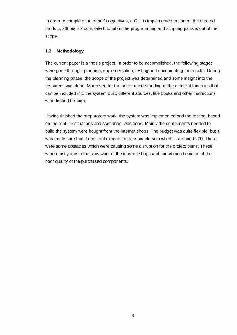
In order to complete the paper's objectives, a GUI is implemented to control the created
product, although a complete tutorial on the programming and scripting parts is out of the
scope.
1.3 Methodology
The current paper is a thesis project. In order to be accomplished, the following stages
were gone through: planning, implementation, testing and documenting the results. During
the planning phase, the scope of the project was determined and some insight into the
resources was done. Moreover, for the better understanding of the different functions that
can be included into the system built, different sources, like books and other instructions
were looked through.
Having finished the preparatory work, the system was implemented and the testing, based
on the real-life situations and scenarios, was done. Mainly the components needed to
build the system were bought from the internet shops. The budget was quite flexible, but it
was made sure that it does not exceed the reasonable sum which is around €200. There
were some obstacles which were causing some disruption for the project plans. These
were mostly due to the slow work of the internet shops and sometimes because of the
poor quality of the purchased components.

4
2 Background
In the current chapter, three budget boards will be analyzed. The most suitable board for
the project is chosen based on the comparison of the available functions and advantages.
The subject of home automation has been discussed during the past years. This chapter
will briefly go through the concepts of the home automation and security. There are home
automation products available off-the-shelf. The problem is that they are quite expensive
and sometimes do not offer a solution to some personal needs. The chapter elaborates
some of these problems.
2.1 Choosing the development board
Today’s computer science students do not have the same skills like students in 1990’s,
that is how Eben Upton felt. It might be due to the rise of more powerful computers and
game consoles, so people do not have the programming skills of the earlier generation.
That was the reason for the RasPi to come into the world with the help of Eben and his
colleagues at the Cambridge University. (Richardson & Wallace 2013, vii)
It might be interesting to know where the name "Raspberry Pi" came from. At its early
stages, the project was called “ABC Micro” by the founders. The name "Raspberry Pi" is
originated due to the long tradition of giving fruit names to computer parts and “Pi” comes
from the word “Python”. The RasPi is not limited to using Python but it is the recommend-
ed programming language for the board. (Upton & Halfacree 2014, 4)
Python is one of a high-level programming languages, such languages are closer to the
human languages like English. It is developed by Guido van Rossum. Python’s goal is to
provide a clear understandable syntax, which makes it a helpful tool for anyone who
wants to learn to code. The programming language can be used on Windows, Linux and
OS X. Python is available for free because it is published under an open-source license.
(Upton & Halfacree 2014, 174)
Performance may be a downside of the Python since it does not run as fast as languages
like C and C++. But this issue seems not to effect the Python's popularity because this
programming language is used by the corporations like Google, CCP Games, ESRI and
many other software developers which value its qualities such as support libraries and
program portability. (Lutz 2013, 23)

5
One of the ways to interact with the RasPi through the internet is by means of the HTTP
protocol, to accomplish that a web server like Apache can be used. The Apache web
server is developed in 1995 by Rob McCool. Apache is an open source software and the
most popular web server on the market according to Netcraft (2015). In addition to
Apache, there are other web servers that can be installed on the RasPi like Lighttpd which
is designed to use less memory. Installing a web server is enough to create a simple web-
site but for developing dynamic and more complex web pages a scripting programming
language like PHP can be used. (Dennis 2013, 94; Upton & Halfacree 2014, 149)
The Raspberry Pi despite its small size is a functional computer capable of handling sim-
ple and complex projects due to its microprocessor. According to the Raspberry Pi Foun-
dation (2015), the board itself is about the size of a credit card, but it can process both
video and audio. The RasPi has connectors that are used to communicate with other de-
vices and the outside world, connectors such as Universal Serial Bus (USB), High-
Definition Multimedia Interface (HDMI) and, of course, General Purpose Input/Output
(GPIO) connectors. (Norris 2014, 1-5)
Figure 1: The Raspberry Pi and its connectors
Each GPIO can be controlled using a programming language like Python. A GPIO can be
used as an input or output pin. Although RasPi’s operating voltage is 5V DC, it is im-
portant to remember that 3.3V DC is the maximum voltage a GPIO can be subjected to.
Connecting a 5V supply to a GPIO will damage the RasPi. (Upton & Halfacree 2014, 222-
223)
6
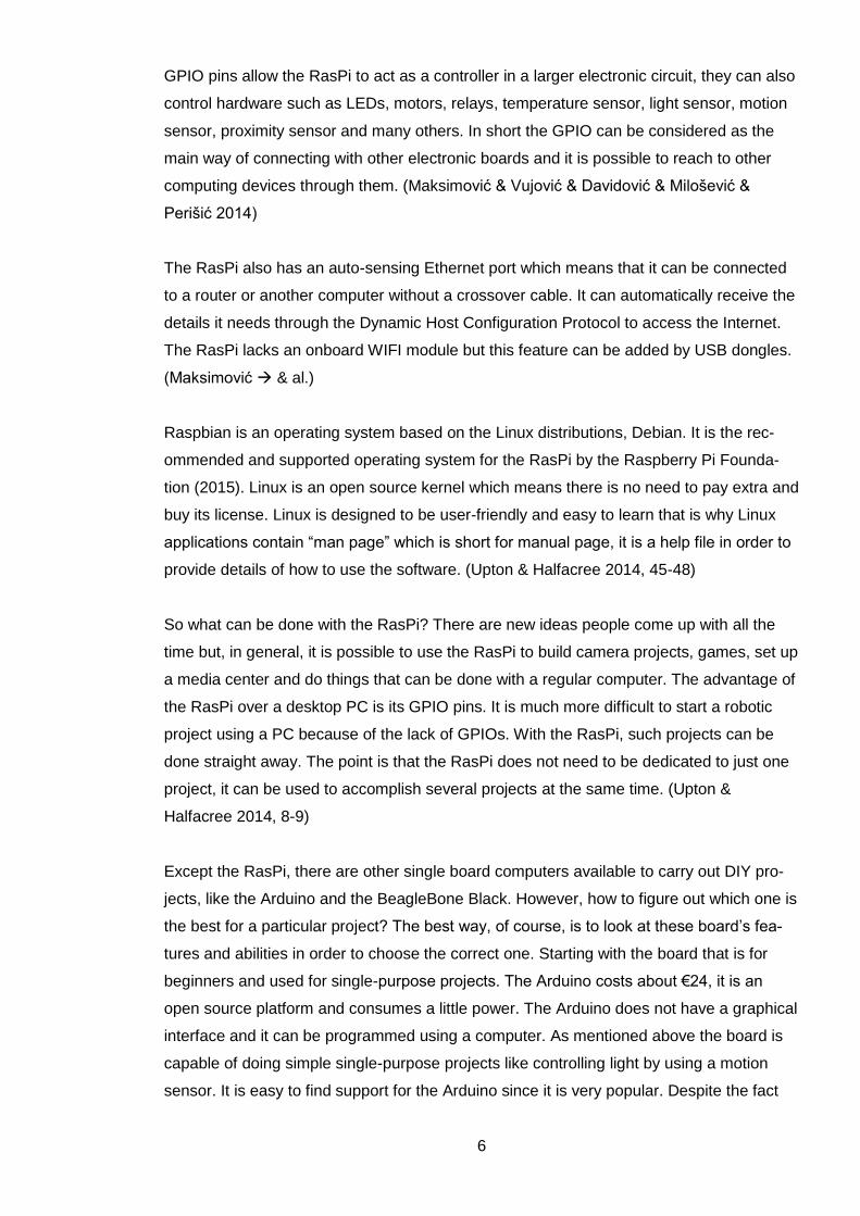
GPIO pins allow the RasPi to act as a controller in a larger electronic circuit, they can also
control hardware such as LEDs, motors, relays, temperature sensor, light sensor, motion
sensor, proximity sensor and many others. In short the GPIO can be considered as the
main way of connecting with other electronic boards and it is possible to reach to other
computing devices through them. (Maksimović & Vujović & Davidović & Milošević &
Perišić 2014)
The RasPi also has an auto-sensing Ethernet port which means that it can be connected
to a router or another computer without a crossover cable. It can automatically receive the
details it needs through the Dynamic Host Configuration Protocol to access the Internet.
The RasPi lacks an onboard WIFI module but this feature can be added by USB dongles.
(Maksimović & al.)
Raspbian is an operating system based on the Linux distributions, Debian. It is the rec-
ommended and supported operating system for the RasPi by the Raspberry Pi Founda-
tion (2015). Linux is an open source kernel which means there is no need to pay extra and
buy its license. Linux is designed to be user-friendly and easy to learn that is why Linux
applications contain “man page” which is short for manual page, it is a help file in order to
provide details of how to use the software. (Upton & Halfacree 2014, 45-48)
So what can be done with the RasPi? There are new ideas people come up with all the
time but, in general, it is possible to use the RasPi to build camera projects, games, set up
a media center and do things that can be done with a regular computer. The advantage of
the RasPi over a desktop PC is its GPIO pins. It is much more difficult to start a robotic
project using a PC because of the lack of GPIOs. With the RasPi, such projects can be
done straight away. The point is that the RasPi does not need to be dedicated to just one
project, it can be used to accomplish several projects at the same time. (Upton &
Halfacree 2014, 8-9)
Except the RasPi, there are other single board computers available to carry out DIY pro-
jects, like the Arduino and the BeagleBone Black. However, how to figure out which one is
the best for a particular project? The best way, of course, is to look at these board’s fea-
tures and abilities in order to choose the correct one. Starting with the board that is for
beginners and used for single-purpose projects. The Arduino costs about €24, it is an
open source platform and consumes a little power. The Arduino does not have a graphical
interface and it can be programmed using a computer. As mentioned above the board is
capable of doing simple single-purpose projects like controlling light by using a motion
sensor. It is easy to find support for the Arduino since it is very popular. Despite the fact
7
that it is designed for beginners, it still takes some times to get used to working with it.
(Klosowski 2013)
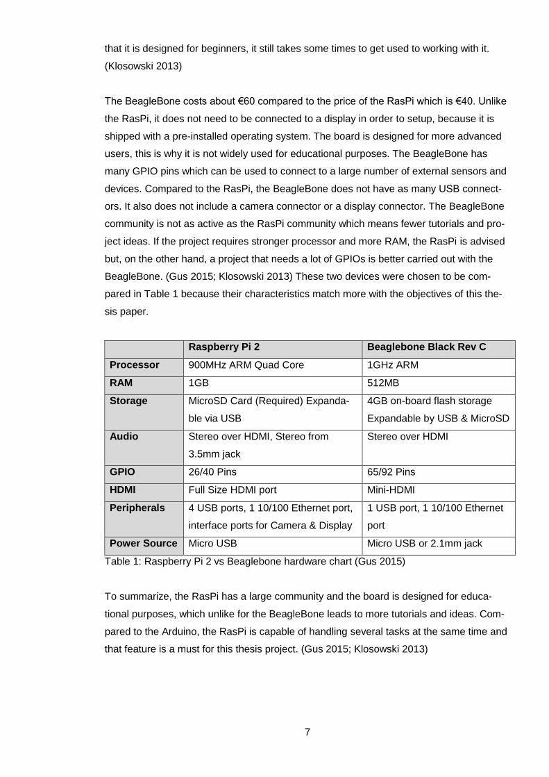
The BeagleBone costs about €60 compared to the price of the RasPi which is €40. Unlike
the RasPi, it does not need to be connected to a display in order to setup, because it is
shipped with a pre-installed operating system. The board is designed for more advanced
users, this is why it is not widely used for educational purposes. The BeagleBone has
many GPIO pins which can be used to connect to a large number of external sensors and
devices. Compared to the RasPi, the BeagleBone does not have as many USB connect-
ors. It also does not include a camera connector or a display connector. The BeagleBone
community is not as active as the RasPi community which means fewer tutorials and pro-
ject ideas. If the project requires stronger processor and more RAM, the RasPi is advised
but, on the other hand, a project that needs a lot of GPIOs is better carried out with the
BeagleBone. (Gus 2015; Klosowski 2013) These two devices were chosen to be com-
pared in Table 1 because their characteristics match more with the objectives of this the-
sis paper.
Raspberry Pi 2 Beaglebone Black Rev C
Processor 900MHz ARM Quad Core 1GHz ARM
RAM 1GB 512MB
Storage MicroSD Card (Required) Expanda-
ble via USB
4GB on-board flash storage
Expandable by USB & MicroSD
Audio Stereo over HDMI, Stereo from
3.5mm jack
Stereo over HDMI
GPIO 26/40 Pins 65/92 Pins
HDMI Full Size HDMI port Mini-HDMI
Peripherals 4 USB ports, 1 10/100 Ethernet port,
interface ports for Camera & Display
1 USB port, 1 10/100 Ethernet
port
Power Source Micro USB Micro USB or 2.1mm jack
Table 1: Raspberry Pi 2 vs Beaglebone hardware chart (Gus 2015)
To summarize, the RasPi has a large community and the board is designed for educa-
tional purposes, which unlike for the BeagleBone leads to more tutorials and ideas. Com-
pared to the Arduino, the RasPi is capable of handling several tasks at the same time and
that feature is a must for this thesis project. (Gus 2015; Klosowski 2013)
8
2.2 Home automation and security system
The 21st century is already the age of smart homes from the point of view of a person
who lived in 1797 if we compare the washing board or igniting a gas lamp to the washing
machine and the light switch. So, are not we living in a smart home already? There is no
need to touch a switch to turn on light, nowadays, a computer can do it automatically. But
there is a difference between what someone needs and what someone wants to auto-
mate. The bottom line is that a smart home must be able to save money. (Velte &
Elsenpeter 2003, 3-7; Jenson 2014)
It is simple to automate the light for an extra cost, but is it really needed or does it really
work as expected? The following examples help us to answer these questions: Walking
into a room can turn on the light automatically but imagine someone is already sleeping in
this room or while wife is watching TV, a system automatically dims the light, in the dark-
ness it will be pretty difficult for the husband to find a book from the bookshelf. But auto-
mation is needed at some level, for example, to turn off all extra lights and the heating
system automatically when no one is home might be a good idea. (Velte & Elsenpeter
2003, 3-7; Jenson 2014)
Tellstick’s product is available in the market today. The label on its box says: “create your
smart home”. The price of €169 includes a package which contains:
Two remotely controlled sockets
A thermometer
One remotely controlled switch with dimming functionality
A sensor that determines whether a door is opened
Another package that costs €209 contains three extra distantly controlled sockets plus a
thermometer for the refrigerator. Product's users are able to control these devices locally
and remotely. (Clas ohlson 2015)
But a smart home is not just about controlling light or some sockets. Here is an example
of a functional home automation system. During the winter, the smart home starts to warm
up the house at 5:30 in the morning because the alarm clock is set for 6:00 o’clock. The
security system was functional all night so it is the time to turn it off automatically. In the
day time, the children are at school and parents are at work, so the system will turn off all
unnecessary devices like the cooker that is left on by mistake. The security system is
turned on again. (Velte & Elsenpeter 2003, 4-7)
9
The homeowner can check on the family pet from work when he has a lunch break be-
cause the smart home can be interacted with by using a web-interface from a long dis-
tance. After a productive day, it is the time to go back home, so the system will turn on the
coffee machine right before everyone’s arrival and raises the temperature in the house.
When it is time to go to sleep, the smart home starts playing relaxing music in all bed-
rooms as soon as people are in bed. The music will be turned off automatically later.
(Velte & Elsenpeter 2003, 4-7)
The arrival of the RasPi changed the concept of the home automation drastically, it has
the power of a PC and also can communicate with the environment around. It is possible
to create cheap systems that are able to interact with some other home devices like the
television by using the RasPi and a smartphone combined. Smartphones can act as a
remote controller for these systems. Thanks to the RasPi, programmers are able to create
software that manipulates their environment. The good news is that it also allows customi-
zation which leads to a personalized and a programmable home automation system.
(Dennis 2013, 21)
A smart home is incomplete without a security system, but usually security systems are
sold as a stand-alone service. There are ways, in general, to set up a security system:
letting the security system to take care of some automation like turning on the light or hav-
ing the security functionality as a part of the smart home, so both systems can collaborate
with each other. For example, it is possible to make the house look as if it is lived in by
using some sensors to turn on the stereo and some lights. If an intrusion occurs, even if
the residents are on the other side of the world, the stereo can play a recording of a bark-
ing dog while the main lights are switched on. (Velte & Elsenpeter 2003, 9)
Security study report done by HP on the home automation systems shows that ten out of
ten tested systems are not immune to the risk of unauthorized access. But there are steps
that if taken can reduce the security risks. It is essential to use a very strong password
and change all the product’s default passwords since they can be found easily on the in-
ternet or from the manual of the product in question. WIFI is another vulnerability that
should be paid attention to, a good password is also strongly advised in this case. Some
of the modern routers allow the user to have more than one access point. It is a good
practice to have an access point just for the home automation system and separate it from
the rest of the network. (HP 2015)
Do not let any unauthorized person modify or even touch the system. A simple act of
pressing “Restore Factory Defaults” button can open all the doors to a hacker. It is very

10
important to make sure the homeowner is the only one who has access to the camera’s
captured view. Sometimes the data travels through a third party’s server and the remote
control functionality is better to be switched off if not needed. It is good to mention that
there is no foolproof method to guarantee the security, but anyway, it should not be made
too easy for the hackers. (HP 2015)
G4S is a company that offers home security services for €39.90 per month. In addition to
the company's services the price also includes:
Three sensors that determine whether the doors are opened
One motion sensor
A motion sensor with camera
Smartphone application and additional devices in order to control the security sys-
tem
The price for each extra detail will be the following: one motion sensor is €55, a motion
sensor with a camera is €120, a door sensor costs €55, an extra remote is €30 and the
price for a smoke detector is €90. The customer must sign a contract for at least 24
months. It will cost €957.60 in total for the basic package. (G4S Kotiturva 2015)
Securitas is another security company in Finland that offers security packages, one of
them is called "24Koti" with an activation fee of €250 plus €31.50 monthly charge. In addi-
tion to the company's services, the price also includes:
One smoke detector
A sensor that determines whether a door is opened
Two motion sensor
Devices in order to control the security system
The customer must sign a contract for at least 36 months. It costs €1,384 in total for this
particular package. The company will send its staff to check the premises in case of mo-
tion or smoke detection, the expense is €50 for Mo 06:00 - Fr 18:00 and €100 for Fr 18:00
- Mo 06:00 including other holidays. (Securitas 24Koti 2015)

11
3 Planning
One of the most important parts of any project is planning. It is essential to know what
must be done in order to turn the list of requirements into a reality. The requirements are
presented in the subchapter "Project questions and objectives".
In the planning phase, the list of requirements is examined and the steps needed to fulfil
them are outlined. The first item on the list says, "Ability to switch on/off some home de-
vices", to complete this, the system should be able to control some power sockets. More-
over, a professional license is needed to work with the main current. Due to the absence
of the license, there are two alternatives left, either to use the radio frequency or WIFI
controlled outlets.
As for temperature measurement, if the option is not used, then there is no need to have
it. But in case the house owner has pets, it is important to keep them at the temperature
that is not too hot, for instance, not higher than 24 degrees Celsius. For this purpose, one
of the outlets must be programmed to switch on a cooling device if the temperature rises
above 24°C.
Another requirement is setting time to turn on and off some home devices. If the residents
of the apartment travel quite often, the timing feature is needed in order to show as if
someone is home by switching on the light at a particular time. This is a way to protect the
house from the potential thieves. This option can also be quite useful if we want to save
up and automate the Christmas lights, so they just switch on when it is dark.
To control the smart home system, creating a website is required. That can be done using
the RasPi as a web-server by installing the Apache and PHP. It is easy to manage the
system from a long distance through a website, but to control the system locally a voice
control is required. The home automation must be simple because nobody is going to log
on to a website to turn on a fan if it is just two meters away. In this situation, a voice con-
trolled switch can come in handy.
Security system requirements are to trigger an alarm and capture a video of an incident if
the home intrusion occurs. It is not wise to keep the video on the RasPi's storage, so the
system must upload the data to an online server. Those people who tend to travel a lot,
sometimes may lack the internet connection and, in this case, it is not enough to send an
email notification about the home intrusion, but an SMS has to be sent as well. If the sur-

12
rounding area is not safe enough or lacks a good reputation, a panic button can be really
useful in order to notify somebody in case of emergency.
Figure 2: An example of a floor plan that shows the position of the security devices
An example of an apartment that accommodates two people is shown in Figure 2. The
building has two floors and the apartment is located on the second floor. The staircase
from the street leads to the entrance. In this example, the most probable way for a thief is
to enter through the main door marked as (a) or to break the window marked as (b). The
bedroom and the living room windows are more difficult to reach due to the height of the
building.
This is why the main attention is paid to the hallway. Shown in Figure 2, the motion sensor
marked as (c) and the camera marked as (d) are facing the window and the door. For the
security reasons the camera is pointed at the corner that the owner is concerned about, it
does not capture any video of the bedroom or the living room.
The other requirement is to switch on the camera and the security system only when no-
body is home. There is no need to enter any code or press any button to enable/disable
the security system and that can be done by using a phone’s Bluetooth. The smart home
system can recognize that nobody is home, if there is no authorized Bluetooth device
found, this is how it switches on the security system and the camera.
13
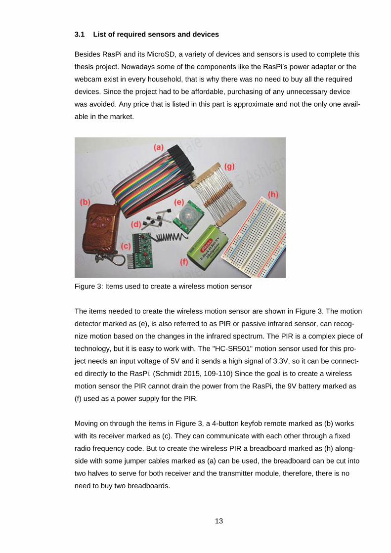
3.1 List of required sensors and devices
Besides RasPi and its MicroSD, a variety of devices and sensors is used to complete this
thesis project. Nowadays some of the components like the RasPi’s power adapter or the
webcam exist in every household, that is why there was no need to buy all the required
devices. Since the project had to be affordable, purchasing of any unnecessary device
was avoided. Any price that is listed in this part is approximate and not the only one avail-
able in the market.
Figure 3: Items used to create a wireless motion sensor
The items needed to create the wireless motion sensor are shown in Figure 3. The motion
detector marked as (e), is also referred to as PIR or passive infrared sensor, can recog-
nize motion based on the changes in the infrared spectrum. The PIR is a complex piece of
technology, but it is easy to work with. The "HC-SR501" motion sensor used for this pro-
ject needs an input voltage of 5V and it sends a high signal of 3.3V, so it can be connect-
ed directly to the RasPi. (Schmidt 2015, 109-110) Since the goal is to create a wireless
motion sensor the PIR cannot drain the power from the RasPi, the 9V battery marked as
(f) used as a power supply for the PIR.
Moving on through the items in Figure 3, a 4-button keyfob remote marked as (b) works
with its receiver marked as (c). They can communicate with each other through a fixed
radio frequency code. But to create the wireless PIR a breadboard marked as (h) along-
side with some jumper cables marked as (a) can be used, the breadboard can be cut into
two halves to serve for both receiver and the transmitter module, therefore, there is no
need to buy two breadboards.

14
The other items in Figure 3 are resistors marked as (g) and a 2N2222 NPN transistor
marked as (d). Two resistors required for this project are a 1 kOhm and a 10 kOhm. Re-
sistors are used to limit the flow of current in order to protect components, in this case, to
prevent the 5V current from reaching the GPIO pin of the RasPi. The NPN transistor used
for this project is acting as a switch for the wireless PIR. More details about this are given
in the implementation part of the paper.
Figure 4: Devices used for creating the smart home functionality
The webcam shown in Figure 4 as item (1) is a Logitech C170 webcam. It has two objec-
tives to carry out concerning this project: to be used as a microphone for the voice control
and a video recording device for the security system. Item (2) is a WIFI controlled socket.
It is not required to use WIFI sockets for home automation since they are quite expensive
in comparison with the item (3) which is a set of three radio frequency controlled outlets.
However, it is possible to find the current status of a WIFI socket by sending a UDP pack-
age to it. This is the feature that RF sockets lack.
Figure 4 includes other items: the 433MHz RF transmitter and receiver kit module marked
as (4), it is used to find out and transmit the on/off codes for RF sockets. This way the
sockets can be controlled with the RasPi. Item (6) is a Bluetooth USB stick used to recog-
nize if someone is at home or not through the connection to another Bluetooth device, like

15
the one in a cell phone. It is required to use a push switch numbered as (7) for the panic
button since on/off switches do not serve well for this purpose.
Huawei E303 3G USB stick with a regular SIM card shown as number (8) in Figure 4 has
three modes: CD mode, web mode and serial mode. In order to use the Huawei E303 to
send SMS, the device must be configured to the serial mode. The 3G modem needs a 5V
power supply just for itself that is why items (9) and (10) which are a USB Hub with a
power adapter are dedicated to the Huawei E303. Item (5) is a normal 5V smartphone
power adapter used to switch on the RasPi.The DS18B20 temperature sensor module
marked as number (11) is used to measure the house temperature and this data will be
used to control a socket. The last item is marked as (12) which is an ordinary computer
speaker that can be connected to the audio jack of the RasPi. The speaker is used for
playing the alarm sound and the Text-to-Speech feature of the voice control.
The total cost of all the details and devices used to complete the bachelor thesis project
can be calculated based on Appendix 1. Listing the prices of a particular detail is quite
useful because it allows calculating the cost of each function of the system separately. For
example, adding a new wireless PIR will cost roughly about €7. Appendix 1 also gives the
information about the shops that items were purchased from. Most of the items were
bought from eBay which is a digital marketplace that enables transactions both between
customer to customer and business to customers. Concerning the prices, usage of RF
sockets is more cost-efficient, since three of them can be bought at the price of one WIFI
socket. Having chosen the parts at the most reasonable prices, which are reflected in Ap-
pendix 1, the total cost of the details for this project is about €155.

16
4 Implementation of a home automation and security system
Project background and the planning phase are followed by the description of the imple-
mentation of a basic smart home system. The chapter is divided into four major parts. The
first part is about setting up the RasPi, the second one is dedicated to the home automa-
tion features of the project, another subchapter is about creating the security system and
the last section covers the creation of a graphical user interface. Despite the fact that this
chapter is divided into the subchapters and each subchapter is devoted to a functionality
of the system, the whole part must be considered as one unit, since the goal is to create a
smart home system with all the functions working together.
4.1 Setting up the Raspberry Pi
RasPi does not come with an OS preinstalled on it, so to start working with the board, a
MicroSD card must be arranged. For the purpose of this thesis Ubuntu Linux is adopted to
copy the recommended OS image which is Raspbian Wheezy to the MicroSD card. The
image can be downloaded directly from the Raspberry Pi Foundation's website.
Figure 5: Output of the df -h command
Raspberry Pi Foundation (2015) has a complete documentation on the subject. The .img
file can be copied to the MicroSD card using the dd tool. In order to find the name and
address of the MicroSD card, df -h command is used, one thing to pay attention to is that
the image must be copied to the whole card not just to a partition. The df -h command's
output /dev/mmcblk0p1 is shown in Figure 5, but the image must be copied to /dev/mmcblk0
since p1 stands for partition one. It is important to unmount the MicroSD card by using the
command umount /dev/mmcblk0p1 before proceeding further. The complete terminal com-
mand for copying the image is the following:
dd bs=4M if=2015-05-05-raspbian-wheezy.img of=/dev/mmcblk0
17
The input file if= is the downloaded .img file from the Raspberry Pi Foundation's website
and the output file of= is the address of the MicroSD card. It is recommended to enter the
command sync after the image is completely copied and before taking the MicroSD card
out of its slot, the command ensures that the cache is flushed to the card.
The RasPi does not have any on/off switch, after inserting the prepared MicroSD it is
enough to use a power adapter to turn the device on. The RasPi has two LEDs, the red
one is the power LED and the green light shows the MicroSD's activity, so everything is
correct if the red light is on and green light is flashing.
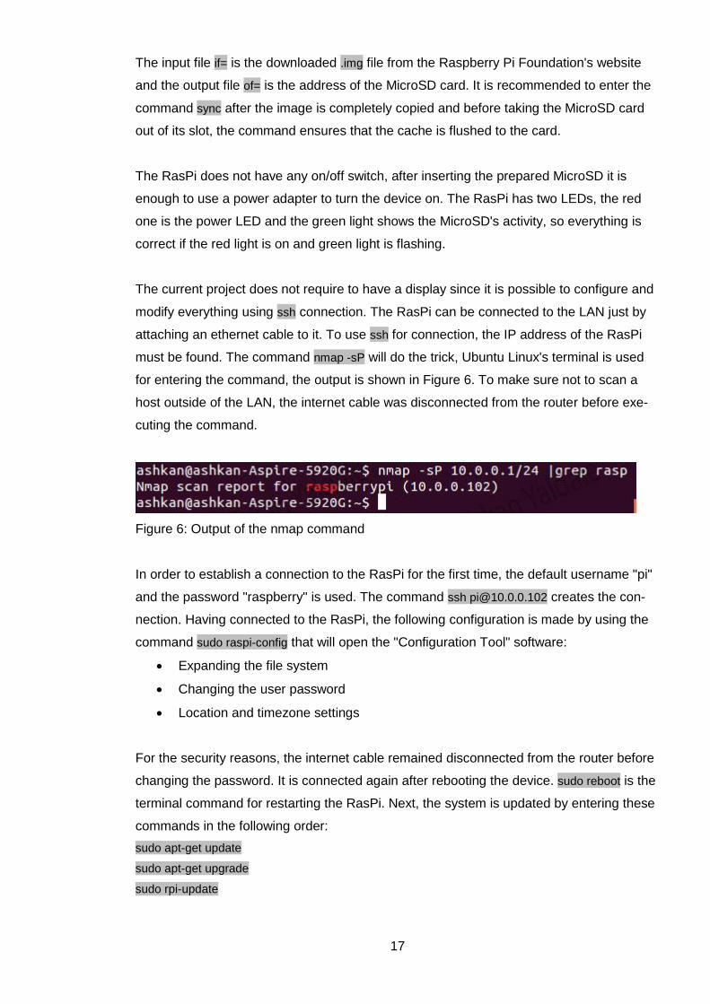
The current project does not require to have a display since it is possible to configure and
modify everything using ssh connection. The RasPi can be connected to the LAN just by
attaching an ethernet cable to it. To use ssh for connection, the IP address of the RasPi
must be found. The command nmap -sP will do the trick, Ubuntu Linux's terminal is used
for entering the command, the output is shown in Figure 6. To make sure not to scan a
host outside of the LAN, the internet cable was disconnected from the router before exe-
cuting the command.
Figure 6: Output of the nmap command
In order to establish a connection to the RasPi for the first time, the default username "pi"
and the password "raspberry" is used. The command ssh [email protected] creates the con-
nection. Having connected to the RasPi, the following configuration is made by using the
command sudo raspi-config that will open the "Configuration Tool" software:
Expanding the file system
Changing the user password
Location and timezone settings
For the security reasons, the internet cable remained disconnected from the router before
changing the password. It is connected again after rebooting the device. sudo reboot is the
terminal command for restarting the RasPi. Next, the system is updated by entering these
commands in the following order:
sudo apt-get update
sudo apt-get upgrade
sudo rpi-update

18
sudo reboot
sudo apt-get autoremove
The RasPi does not have a Real Time Clock (RTC), so the time and date must be updat-
ed if the RasPi is unplugged from its power source. That can be done manually as well,
but cron command is used to automate the task for this project. It is necessary to have a
brief explanation about the cron table since it is used often for this thesis work. It is possi-
ble to display or edit the cron table by using the following terminal commands:
crontab -e # Opening the cron table for editing
crontab -l # Displaying the cron table
The cron table can be used in order to execute a command at a given time. These com-
mands can be set for each user by using the crontab command. The system will check the
table regularly to see if there is a new command scheduled to be executed. An example of
the cron table syntax is shown in Table 2. (Hows & Membrey 2012, 107)
Min (0 - 59) Hour (0 -
23)
Day of Month
(1 - 31)
Month (1 -
12)
Day of
Week (0 - 6)
Command
10 6 * * 0 sudo reboot
10th Minute 6:00 AM Every Day Every Month On Sunday Shell Com-
mand
Table 2: Example of a crontab command (Hows & Membrey 2012, 107)
The example presented in Table 2 10 6 * * 0 sudo reboot will reboot the system once per
week on Sunday at 6:10 AM. In order to update the time and date once per hour, the fol-
lowing cron job is entered into the cron table: 0 * * * * sudo dpkg-reconfigure ntp. This con-
cludes the basic setup for the RasPi, of course, the rest of installations is covered in the
related sections of the paper.
4.2 Home automation
This subchapter is devoted to the development of the home automation part of the project.
It contains the description of how to manage remote controlled power sockets with the
RasPi as well as how to use the home temperature and time in order to control some
home devices. The part also explains how to handle home automation's functionalities
with voice commands.

19
4.2.1 WIFI sockets
Štikonas (2015) offers a description of how to reverse engineer the device used for this
project. As stated earlier, it is possible for the RasPi to use UDP as a mean of communi-
cation with a WIFI socket. The difficult part is to find out about the content of these pack-
ages. That can be done by monitoring the LAN while turning the device on/off using its
related application. Wireshark is a free and an open source application that can be used
to monitor the home network's activity. Figure 7 shows the UDP packages that are cap-
tured specifically for this paper by using the Wireshark packet analyzer. The blurred area
contains some confidential information like the MAC address of the WIFI socket and
should not be shared.
Figure 7: Communication with the WIFI socket
It is possible to use the terminal in order to control the socket, once the packages are dis-
covered. The shell script below can do the task, the script accepts arguments which can
turn on/off the device. Executing the script without any argument will return the current
status of the WIFI socket.
#!/bin/bash #sockets.sh v1.00, Štikonas (2015) #WIFI socket's IP address is 10.0.0.104 echo '6864001e636c<MAC>202020202020<Reverse-MAC>202020202020' | xxd -r -p \ | nc -u -w2 -p '10000' '10.0.0.104' '10000' | xxd -r if [ "$1" = "on" ]; then echo '686400176463<MAC>2020202020200000000001' | xxd -r -p \ | nc -n -4u -w1 '10.0.0.104' '10000' elif [ "$1" = "off" ]; then echo '686400176463<MAC>2020202020200000000000' | xxd -r -p \ | nc -n -4u -w1 '10.0.0.104' '10000' else echo '6864001e636c<MAC>202020202020<Reverse-MAC>202020202020' | xxd -r -p \ | nc -u -w2 -p '10000' '10.0.0.104' '10000' | xxd -p | cut -c47-49 fi
20
Here is an example of a MAC address 00:0a:95:9d:68:16. The code above requires the
MAC address in reverse which will look like this 16:68:9d:95:0a:00.
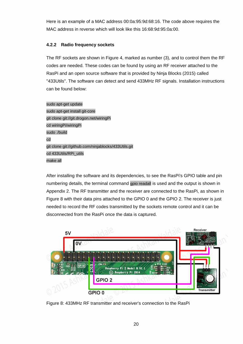
4.2.2 Radio frequency sockets
The RF sockets are shown in Figure 4, marked as number (3), and to control them the RF
codes are needed. These codes can be found by using an RF receiver attached to the
RasPi and an open source software that is provided by Ninja Blocks (2015) called
"433Utils". The software can detect and send 433MHz RF signals. Installation instructions
can be found below:
sudo apt-get update
sudo apt-get install git-core
git clone git://git.drogon.net/wiringPi
cd wiringPi/wiringPi
sudo ./build
cd
git clone git://github.com/ninjablocks/433Utils.git
cd 433Utils/RPi_utils
make all
After installing the software and its dependencies, to see the RasPi's GPIO table and pin
numbering details, the terminal command gpio readall is used and the output is shown in
Appendix 2. The RF transmitter and the receiver are connected to the RasPi, as shown in
Figure 8 with their data pins attached to the GPIO 0 and the GPIO 2. The receiver is just
needed to record the RF codes transmitted by the sockets remote control and it can be
disconnected from the RasPi once the data is captured.
Figure 8: 433MHz RF transmitter and receiver's connection to the RasPi

21
The next step is to press each of the six buttons on the remote control that is included into
the RF socket set. Each button will produce a code and it can be captured by using the
terminal command sudo 433Utils/RPi_utils/RFSniffer. The command's output is something
like this: Received 5592332. The codes are then written down and used with the next com-
mand: sudo 433Utils/RPi_utils/codesend 5592332 to switch on/off the sockets. During the
development phase, it is discovered that the RF transmitter does not work well if there is a
distance between the transmitter itself and the sockets. The problem is fixed by soldering
an antenna to the transmitter.
The bash script "sockets.sh" presented in the previous subchapter "WIFI sockets" is com-
pleted by using the available information about the RF sockets. A full script can be found
in Appendix 3. The new bash script will accept two arguments, the first one is to identify a
socket and the second one is the on/off command. The script is also used for the next
subchapter in order to control the sockets through the home temperature and the timer.
4.2.3 Controlling the sockets using home temperature and timer
The DS18B20, marked as (11) in Figure 4, is a waterproof digital thermometer that can be
powered using a power supply in the range of 3V to 5.5V and it can measure tempera-
tures from -55°C to +125°C with an accuracy of ±0.5°C from -10°C to +85°C. The
DS18B20 contains a unique silicon serial number which means multiple thermometers
can exist on the same 1-Wire bus. The waterproof DS18B20 has three cables: ground,
data in/out and one for the power supply. (Maxim Integrated 2008)
In order to connect the DS18B20 to the RasPi, a ready-made Shield Module is used. The
data wire is attached to the GPIO 7 and the complete wiring diagram is shown in Figure 9.
It is important to mention that the GPIO numbering for this project is based on the GPIO
table presented in Appendix 2.
Figure 9: Wiring diagram for the temperature sensor
22
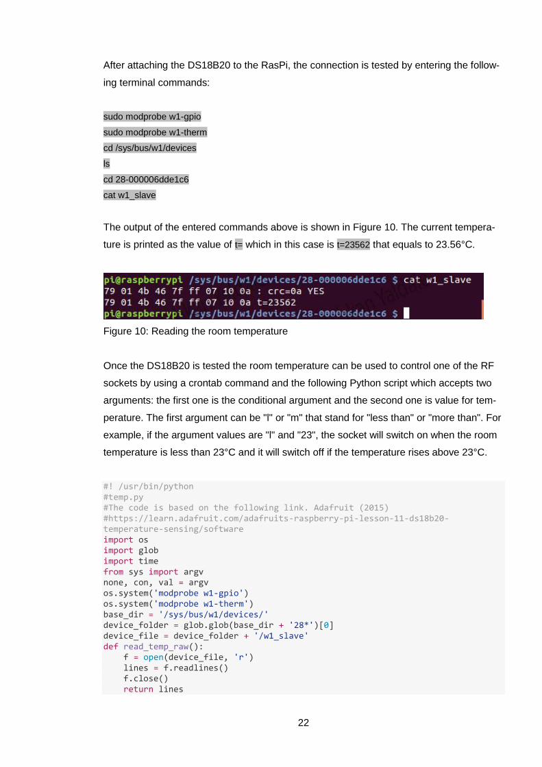
After attaching the DS18B20 to the RasPi, the connection is tested by entering the follow-
ing terminal commands:
sudo modprobe w1-gpio
sudo modprobe w1-therm
cd /sys/bus/w1/devices
ls
cd 28-000006dde1c6
cat w1_slave
The output of the entered commands above is shown in Figure 10. The current tempera-
ture is printed as the value of t= which in this case is t=23562 that equals to 23.56°C.
Figure 10: Reading the room temperature
Once the DS18B20 is tested the room temperature can be used to control one of the RF
sockets by using a crontab command and the following Python script which accepts two
arguments: the first one is the conditional argument and the second one is value for tem-
perature. The first argument can be "l" or "m" that stand for "less than" or "more than". For
example, if the argument values are "l" and "23", the socket will switch on when the room
temperature is less than 23°C and it will switch off if the temperature rises above 23°C.
#! /usr/bin/python #temp.py #The code is based on the following link. Adafruit (2015) #https://learn.adafruit.com/adafruits-raspberry-pi-lesson-11-ds18b20-temperature-sensing/software import os import glob import time from sys import argv none, con, val = argv os.system('modprobe w1-gpio') os.system('modprobe w1-therm') base_dir = '/sys/bus/w1/devices/' device_folder = glob.glob(base_dir + '28*')[0] device_file = device_folder + '/w1_slave' def read_temp_raw(): f = open(device_file, 'r') lines = f.readlines() f.close() return lines

23
def read_temp(): lines = read_temp_raw() while lines[0].strip()[-3:] != 'YES': time.sleep(0.2) lines = read_temp_raw() equals_pos = lines[1].find('t=') if equals_pos != -1: temp_string = lines[1][equals_pos+2:] temp_c = float(temp_string) / 1000.0 return int(round(temp_c)) if con == 'm' : if read_temp() > int(val) : os.system('/bin/bash -l /home/pi/sockets.sh 2 on') else: os.system('/bin/bash -l /home/pi/sockets.sh 2 off') if con == 'l' : if read_temp() < int(val) : os.system('/bin/bash -l /home/pi/sockets.sh 2 on') else: os.system('/bin/bash -l /home/pi/sockets.sh 2 off')
The script "temp.py" is used to build the cron job. The following command is entered to
the cron table in order to execute the "temp.py" script in the background every minute:
*/1 * * * * nohup sudo python /home/pi/temp.py m 24 > /dev/null 2>&1&
This way the temperature will be checked regularly and in response, the socket number 2
that is connected to an air conditioner will be switched on when the room temperature is
above 24°C.
The cron table is also used for the final part of this subchapter which is controlling a sock-
et with a timer. Since all the preparations are done, the only thing needed is to enter the
following lines to the cron table:
00 16 * * * /bin/bash -l /home/pi/sockets.sh 3 on
00 08 * * * /bin/bash -l /home/pi/sockets.sh 3 off
This will switch on the socket number 3 that is connected to the Christmas lights at 16:00
o’clock and switch it off at 08:00 o’clock. Table 2 contains the details about the cron com-
mands.
The tasks related to controlling the sockets by using home temperature and timer are
completed in this subchapter. The cron table modification can be done through a GUI and
the details are found in the chapter devoted to the creation of a graphical user interface.

24
4.2.4 Voice control
There are some challenges in the way of building a smart home, one of them is to discov-
er a way to control the home devices. Of course, some routine tasks can be automated
like turning on the air conditioner when the home temperature rises or to turn on/off the
fish tank's air pump at the specific time. But what about turning on the printer in the other
room while working with a laptop or to turn off the desktop PC in the bedroom while cook-
ing in the kitchen. It is necessary to have some sort of controlling scheme for the smart
home.
One of the things that comes to mind when talking about controlling devices is to have
infrared remote control, but this method is not very useful for a 21st century smart home
since even today's television can be controlled by using hand gestures. So having an in-
frared remote for this project is out of the question.
It makes sense to control the home automation system using the web interface from a
distance but using a mobile web browser to control the system locally does not make
sense. That is why a voice control function is added to the project in order to control the
home devices locally.
In order to add the voice control feature to the project a microphone is required. As stated
in the subchapter "List of required sensors and devices", a webcam is used for this pur-
pose. The other requirements are a speaker and an open source software "PiAUISuite"
that is provided by Hickson (2015). After connecting the webcam and the speaker to the
RasPi, the software is installed:
git clone git://github.com/StevenHickson/PiAUISuite.git
cd PiAUISuite/Install/
./InstallAUISuite.sh
The suite "PiAUISuite" contains several applications, but this project uses the
"Voicecommand". To configure it, the voicecommand -s command is entered and to change
the configuration manually voicecommand -e is used. The config file contains the following:
!continuous==1 !verify==1 !ignore==1 !filler==0 !thresh==9.019652 !keyword==voice !response==Yes

25
!improper==I didn't get the command
Since now the voice control installation is completed, commands can be added to the con-
fig file, for example:
turn on lamp==sudo sh /home/pi/sockets.sh 1 on;tts "done" turn off lamp==sudo sh /home/pi/sockets.sh 1 off;tts "done" turn on PC==sudo python /home/pi/wol.py on;tts "done" turn off PC==sudo python /home/pi/wol.py off;tts "done"
If the WIFI socket is connected to a desk lamp, it will be turned on by saying "turn on
lamp". The program will reply "done" after turning on the lamp and the same process is
valid for turning off the lamp.
There are other things that can be done using the voice control, for instance, turning on/off
a Windows PC, if both RasPi and the PC are on the same LAN. This is reflected in the
following code:
#!/usr/bin/env python #wol.py #The code is based on the following link. How-To Geek (2015) #http://www.howtogeek.com/109655/how-to-remotely-shut-down-or-restart-windows-pcs/ import socket from sys import argv import os import time none, con = argv if con == 'on': s=socket.socket(socket.AF_INET, socket.SOCK_DGRAM) s.setsockopt(socket.SOL_SOCKET, socket.SO_BROADCAST, 1) s.sendto('\xff'*6+'<PC-MAC>'*16, ("255.255.255.255",9)) if con == 'off': for i in range(0, 3): os.system('net rpc shutdown -I 10.0.0.100 -U user%password) time.sleep(5)
During the project development, it is discovered that most of the time the PC does not
switch off by sending just one shutdown package to it, that is why in the code a for-loop
will send the package more than once. In addition, proper Windows configuration is pro-
vided but the detailed information on the subject is out of the scope of the paper.
26
4.3 Security system
The current chapter is set to complete the previous one by adding a security system to the
smart home product. The goals and the required devices for this chapter are mentioned in
the planning part of this bachelor thesis. The chapter contains instructions on sending an
SMS and email notifications to the homeowner in case of an intrusion. A video clip of the
incident will be captured and uploaded to the cloud. The chapter also gives guidance on
how to create a panic button and a wireless motion detector. Finally, the security system
will be controlled by using a Bluetooth device.
4.3.1 Creating a wireless motion sensor
For this subchapter, a wireless remote control and receiver are used, marked as (b) and
(c) in Figure 3. The transmitter and the receiver are linked together and use fixed RF
codes to communicate. The remote control has four buttons and by pressing each button,
the receiver will release a high voltage of 5V through its output pins.
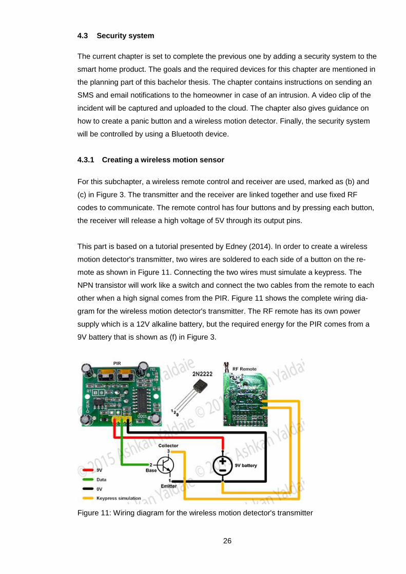
This part is based on a tutorial presented by Edney (2014). In order to create a wireless
motion detector's transmitter, two wires are soldered to each side of a button on the re-
mote as shown in Figure 11. Connecting the two wires must simulate a keypress. The
NPN transistor will work like a switch and connect the two cables from the remote to each
other when a high signal comes from the PIR. Figure 11 shows the complete wiring dia-
gram for the wireless motion detector's transmitter. The RF remote has its own power
supply which is a 12V alkaline battery, but the required energy for the PIR comes from a
9V battery that is shown as (f) in Figure 3.
Figure 11: Wiring diagram for the wireless motion detector's transmitter
27
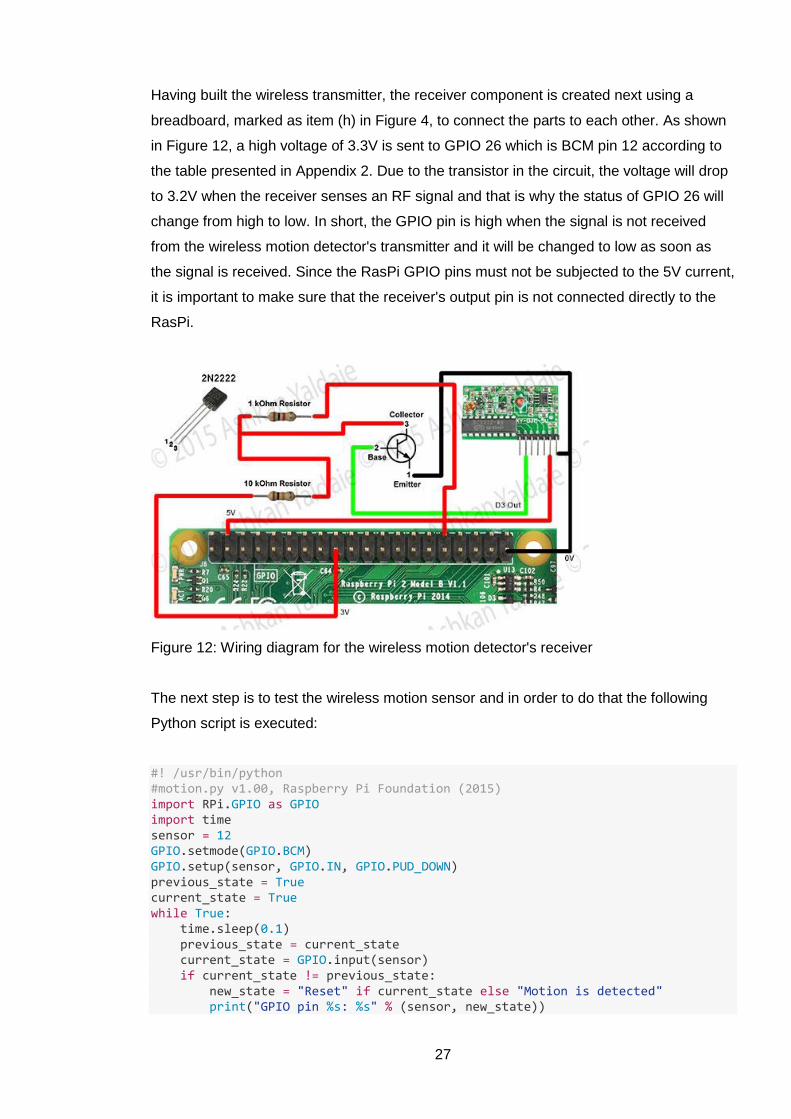
Having built the wireless transmitter, the receiver component is created next using a
breadboard, marked as item (h) in Figure 4, to connect the parts to each other. As shown
in Figure 12, a high voltage of 3.3V is sent to GPIO 26 which is BCM pin 12 according to
the table presented in Appendix 2. Due to the transistor in the circuit, the voltage will drop
to 3.2V when the receiver senses an RF signal and that is why the status of GPIO 26 will
change from high to low. In short, the GPIO pin is high when the signal is not received
from the wireless motion detector's transmitter and it will be changed to low as soon as
the signal is received. Since the RasPi GPIO pins must not be subjected to the 5V current,
it is important to make sure that the receiver's output pin is not connected directly to the
RasPi.
Figure 12: Wiring diagram for the wireless motion detector's receiver
The next step is to test the wireless motion sensor and in order to do that the following
Python script is executed:
#! /usr/bin/python #motion.py v1.00, Raspberry Pi Foundation (2015) import RPi.GPIO as GPIO import time sensor = 12 GPIO.setmode(GPIO.BCM) GPIO.setup(sensor, GPIO.IN, GPIO.PUD_DOWN) previous_state = True current_state = True while True: time.sleep(0.1) previous_state = current_state current_state = GPIO.input(sensor) if current_state != previous_state: new_state = "Reset" if current_state else "Motion is detected" print("GPIO pin %s: %s" % (sensor, new_state))
28
Basically, the script reacts to the changes in the status of the BCM pin 12. A while-loop
checks the pins status regularly and prints the corresponding text accordingly. The same
script is modified in the next subchapter in order to send an SMS and trigger an alarm if
the motion is detected.
4.3.2 Sending an SMS and triggering the alarm if motion is detected
The security system has to be able to notify the homeowner by sending an SMS if a home
intrusion occurs. Based on the planning chapter, the system must also be able to trigger
an alarm if a motion is detected while the owner is not home. The current subchapter is
focused on both issues mentioned above. The information used in this part is collected
from the Raspberry Pi Foundation (2015) forums.
A 3G USB modem is used in order to send an SMS, the device is shown in Figure 4 as
number (8). One of the issues with this device is power consumption, since it needs to
have its own power supply, items (9) and (10) are also added to the list of devices re-
quired to complete this project.
The other issue is that the 3G modem is by default on the storage or CD mode. It is easy
to change the device's settings using a GUI like a browser, but all that is available for this
project is the terminal window, so the 3G modem's setting is changed automatically after
every reboot from CD mode to web mode and finally to the serial mode. There can be
other modems which are more compatible with the RasPi but the current 3G modem is
used, since one of the goals of the project is to use the available devices and not to pur-
chase anything unless it is absolutely necessary.
In order to change the settings from CD mode to web mode, the following lines are added
to the "/etc/usb_modeswitch.conf" file using the nano text editor:
# Huawei E353 (3.se) DefaultVendor= 0x12d1 DefaultProduct=0x1f01 TargetVendor= 0x12d1 TargetProduct= 0x14db MessageContent="55534243123456780000000000000a11062000000000000100000000000000"
The second step which is changing the settings from the web mode to the serial mode is
done using a bash script:
#!/bin/bash

29
#superscript.sh, Raspberry Pi Foundation (2015) url="http://192.168.1.1/api/device/mode" xmlheader="<?xml version=\"1.0\" encoding=\"UTF-8\"?>" data="<request><mode>0</mode></request>" ifconfig eth1 192.168.1.10 netmask 255.255.255.0 wget --post-data="$xmlheader$data" $url -qO-
The above script is then called after every reboot using the crontab's entry:
@reboot sudo sh /home/pi/superscript.sh
To send an SMS using the 3G modem a software is required, Gammu is used in order to
control the modem for this project. To install the Gammu the following command is used:
sudo apt-get install gammu. In order to test the 3G modem's connection, the command sudo
gammu --identify is entered to the terminal and the output is shown in Figure 13.
Figure 13: Connection to the 3G modem
Moving on to the next requirement which is playing an alarm sound, a program called VLC
is installed sudo apt-get install vlc. An MP3 file is also prepared to be played as an alarm, it
can be the sound of a barking dog, speaking crowd or simply a sound of an alarm. Both
SMS notification and triggering the alarm can be added to the security system by modify-
ing the code "motion.py" presented in the previous subchapter.
#! /usr/bin/python #motion.py v2.00, Raspberry Pi Foundation (2015) import os import commands import RPi.GPIO as GPIO import time from datetime import datetime, timedelta sensor = 12 GPIO.setmode(GPIO.BCM) GPIO.setup(sensor, GPIO.IN, GPIO.PUD_DOWN) previous_state = True current_state = True NOW = datetime.now() SMS = True SMS_TIME = datetime.now() + timedelta(days=300) def PIR():

30
global SMS global SMS_TIME if SMS: print "SMS Sent!" SMS_TIME = datetime.now() + timedelta(minutes=10) os.system("sudo -H -u pi echo 'Motion is detected!' | gammu --sendsms TEXT +3584076XXXXX") SMS = False os.system("sudo -H -u pi cvlc /home/pi/alarm.mp3 vlc://quit") return while True: NOW = datetime.now() if SMS_TIME <= NOW: SMS = True time.sleep(0.1) previous_state = current_state current_state = GPIO.input(sensor) if current_state != previous_state: if (current_state == False): print "Motion is detected" + datetime.now().strftime("%d-%m-%Y %H:%M") PIR() elif (current_state == True): print "Sensor reset!"
The above-mentioned Python script will send an SMS to the added phone number and
play the "alarm.mp3" if a motion is detected. In order to avoid sending rapid SMSs for
each movement that occurs in the range of the PIR, a delay for ten minutes is added be-
fore sending a new text message. But the script’s execution will continue since the alarm
file will be played within these ten minutes if a motion is detected. The system is controlled
by using a Bluetooth device through a website and minor changes are done to the final
script, descriptions can be found in the following parts of this paper.
4.3.3 Implementation of a panic button
Based on the project requirement, a panic button is implemented to be used in the case of
emergency, if a home resident wants to inform others. The system is set to send a text
message notification by pushing the button. The button is connected to the GPIO 28
which is BCM pin 20 and the complete wiring diagram is given in Figure 14.
Figure 14: Wiring diagram for the panic button

31
As shown in Figure 14, a 3.3V current is connected to the GPIO pin through the button. A
high signal will be sent to the GPIO 28, if the panic button is pushed using the Python
script below:
#! /usr/bin/python #panic.py, Raspberry Pi Foundation (2015) import RPi.GPIO as GPIO import time import os sensor = 20 GPIO.setmode(GPIO.BCM) GPIO.setup(sensor, GPIO.IN, GPIO.PUD_DOWN) current_state = False while True: time.sleep(0.3) current_state = GPIO.input(sensor) if current_state == True: print("GPIO pin %s is %s" % (sensor, "PRESSED")) os.system("sudo -H -u pi echo 'Panic Notification!' | gammu --sendsms TEXT +3584076XXXXX 2> /dev/null &") time.sleep(20)
The script is set to be executed after every reboot through the cron table @reboot sudo
python /home/pi/panic.py. In order to avoid sending several SMSs at a time, the code's exe-
cution will be paused for 20 seconds after sending a text message. The panic button is
sharing the 3.3V pin with the wiring diagram that is shown in Figure 12 and that might in-
terfere with the wireless motion detector, but this is not an issue for this project since the
panic button is set to be used when at least one of the residents is home, so the motion
detector is disarmed.
4.3.4 Connecting a camera to the system to capture a video clip of an intrusion
One of the requirements set for this thesis project is to capture a video clip of a home in-
trusion. The camera which is already connected to the RasPi for the voice control func-
tionality is used in this subchapter as well. It is shown in Figure 4 as item (1). The VLC
player's installation was described in an earlier subchapter. It can record the video clip by
using the following terminal command:
#VideoLAN's Wiki (2015) cvlc v4l2:///dev/video0 \:sout='#transcode{vcodec=mp4v,vb=5000,scale=1,fps=30,acodec=mpga,ab=128,\ chan-nels=1,samplerate=44100}:duplicate{dst=std{access=file,mux=ts,dst=clip.mpg}}' --run-time=10 vlc://quit

32
This will record a ten seconds clip and save it as "clip.mpg". The command was overwrit-
ing the file on each execution, but the problem was fixed in the Python script below:
#! /usr/bin/python #vlc.py v1.00, VideoLAN's Wiki (2015) import os from datetime import datetime i = datetime.now() fileName = i.strftime('%d-%m-%Y_%H.%M.%S') + ".mpg" os.system("cvlc v4l2:///dev/video0 :sout='#transcode{vcodec=mp4v,vb=5000,scale=1,fps=30,acodec=mpga,ab=128,\ channels=1,samplerate=44100}:duplicate{dst=std{access=file,\ mux=ts,dst=clip_"+ str(fileName) +"}}' --run-time=10 vlc://quit")
The script will basically add date and time including seconds to the name of the file, so
every file is going to have a unique name. This Python code can then be executed when-
ever a motion is detected by modifying the "motion.py" script. The final version of it can be
found in Appendix 4.
Figure 15: IP camera RTSP address
Besides, a USB webcam that is adopted for this project other devices such as a wireless
IP camera can be used to record a video through a RasPi. Such devices may have The
Real Time Streaming Protocol (RTSP) to stream their captured video. The RTSP address
can usually be found from the settings of the IP camera as shown in Figure 15. To con-
nect to the IP camera and record its captured video, the following terminal command can
be applied:
#VideoLAN's Wiki (2015) cvlc rtsp://username:[email protected]:port/udp/av0_0 --sout=clip.mpg --run-time=10 vlc://quit
The next subchapter contains the description of how to send an email notification and
upload a video file to the cloud by using the RasPi and a Google Application Program In-
terface (API).

33
4.3.5 Uploading the video to the cloud and sending an email notification
The video that will be captured on motion detection from the previous subchapter's in-
structions is stored on the RasPi's local storage. It is important to keep the RasPi in a safe
and hidden place in the house since it also takes care of home security. The RasPi can be
damaged during a possible robbery and to avoid that the file will be uploaded to the cloud.
This part is based on the instruction provided by Blythe (2015).
It is a good idea to have a separate Google account for this part of the project and not to
use any personal account. Google Drive then can be used to store video files by enabling
the Drive API within the Google Developers Console which is configured through the fol-
lowing instructions:
Go to https://code.google.com/apis/console
Create a project called "Uploader"
Choose "Enable and manage APIs" then "Drive API" and click on the "Enable API"
button
Click on "Go to Credentials", then "client ID" and click "Configure Consent Screen"
Set the product name to "Uploader" and click "Save"
Choose "Other" and click "Create"
Click on the created client and download the JSON file
Rename it to client_secrets.json and put it in RasPi storage "/home/pi/"
The commands below are then entered in the terminal window:
git clone https://github.com/jerbly/motion-uploader.git
sudo pip install --upgrade google-api-python-client
cd motion-uploader
chmod a+x uploader.py
The next step is to modify the "uploader.cfg" file using the nano editor. The file must con-
tain the login information for the created Gmail account, the path to the JSON file
"/home/pi/", the name of the Google drive folder to store video file and an email address to
get the notification.
To test the API and related configuration, the terminal command uploader.py uploader.cfg
/home/pi/clip.mpg is executed in the folder "motion-uploader". This will upload the file
34
"clip.mpg" to the Google Drive. For the first time use, the system asked for "Authorization
Code" that can be found via the given link by the notification message.
The final step of this subchapter is to edit the python script "vlc.py" from the previous sub-
chapter.
#! /usr/bin/python #vlc.py v1.50, VideoLAN's Wiki (2015) import os from datetime import datetime i = datetime.now() fileName = i.strftime('%d-%m-%Y_%H.%M.%S') + ".mpg" os.system("cvlc v4l2:///dev/video0 :sout='#transcode{vcodec=mp4v,vb=5000,scale=1,fps=30,acodec=mpga,ab=128,\ channels=1,samplerate=44100}:duplicate{dst=std{access=file,\ mux=ts,dst=clip_"+ str(fileName) +"}}' --run-time=10 vlc://quit") os.system("/home/pi/motion-uploader/uploader.py /home/pi/motion-uploader/uploader.cfg clip_"+ str(fileName))
The code basically uploads the captured file to the Google Drive by using the given con-
figuration from the file "uploader.cfg".
By now the smart home's security system can detect a home intrusion by using the creat-
ed wireless motion sensor and trigger an alarm, it can then inform the homeowner through
an SMS and an email notification. It can also capture a video file of the instruction and
store it to the internal storage and to the cloud.
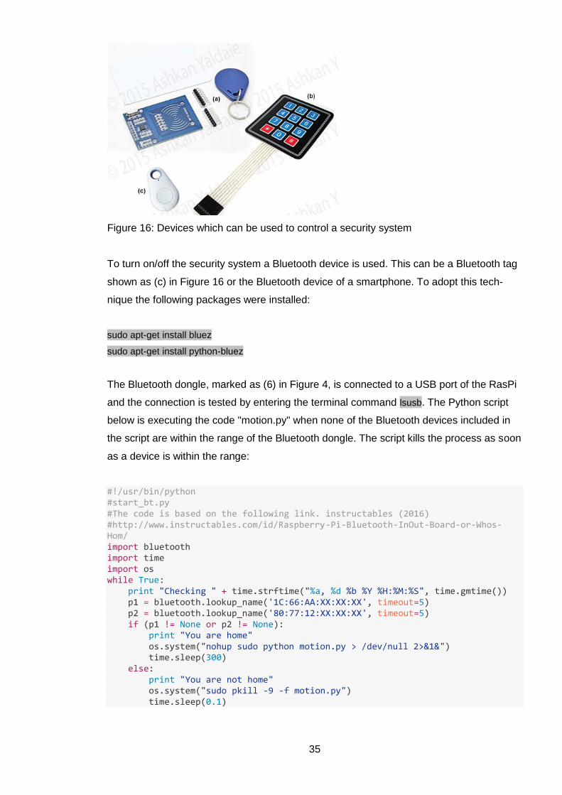
4.3.6 Controlling the security system via Bluetooth
To be completed, the security system needs to be turn on/off at the right time. This can be
done by using a keypad shown as (b) in Figure 16 to enter the security code or by having
a Radio-Frequency Identification (RFID), item (a) in Figure 16. But these methods are not
utilized for this project.
35
Figure 16: Devices which can be used to control a security system
To turn on/off the security system a Bluetooth device is used. This can be a Bluetooth tag
shown as (c) in Figure 16 or the Bluetooth device of a smartphone. To adopt this tech-
nique the following packages were installed:
sudo apt-get install bluez
sudo apt-get install python-bluez
The Bluetooth dongle, marked as (6) in Figure 4, is connected to a USB port of the RasPi
and the connection is tested by entering the terminal command lsusb. The Python script
below is executing the code "motion.py" when none of the Bluetooth devices included in
the script are within the range of the Bluetooth dongle. The script kills the process as soon
as a device is within the range:
#!/usr/bin/python #start_bt.py #The code is based on the following link. instructables (2016) #http://www.instructables.com/id/Raspberry-Pi-Bluetooth-InOut-Board-or-Whos-Hom/ import bluetooth import time import os while True: print "Checking " + time.strftime("%a, %d %b %Y %H:%M:%S", time.gmtime()) p1 = bluetooth.lookup_name('1C:66:AA:XX:XX:XX', timeout=5) p2 = bluetooth.lookup_name('80:77:12:XX:XX:XX', timeout=5) if (p1 != None or p2 != None): print "You are home" os.system("nohup sudo python motion.py > /dev/null 2>&1&") time.sleep(300) else: print "You are not home" os.system("sudo pkill -9 -f motion.py") time.sleep(0.1)
36
There is no need to pair the Bluetooth devices with the Bluetooth dongle. As shown in the
script above, the MAC addresses of the Bluetooth devices are required in order for the
script to work. Samsung Galaxy S2 is used to turn on/off the security system automatically
without a need of pressing any button or entering any code.
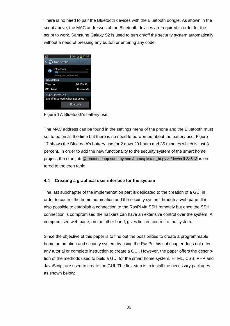
Figure 17: Bluetooth's battery use
The MAC address can be found in the settings menu of the phone and the Bluetooth must
set to be on all the time but there is no need to be worried about the battery use. Figure
17 shows the Bluetooth's battery use for 2 days 20 hours and 35 minutes which is just 3
percent. In order to add the new functionality to the security system of the smart home
project, the cron job @reboot nohup sudo python /home/pi/start_bt.py > /dev/null 2>&1& is en-
tered to the cron table.
4.4 Creating a graphical user interface for the system
The last subchapter of the implementation part is dedicated to the creation of a GUI in
order to control the home automation and the security system through a web page. It is
also possible to establish a connection to the RasPi via SSH remotely but once the SSH
connection is compromised the hackers can have an extensive control over the system. A
compromised web page, on the other hand, gives limited control to the system.
Since the objective of this paper is to find out the possibilities to create a programmable
home automation and security system by using the RasPi, this subchapter does not offer
any tutorial or complete instruction to create a GUI. However, the paper offers the descrip-
tion of the methods used to build a GUI for the smart home system. HTML, CSS, PHP and
JavaScript are used to create the GUI. The first step is to install the necessary packages
as shown below:

37
sudo apt-get update
sudo apt-get install apache2 -y
sudo apt-get install php5 libapache2-mod-php5 –y
A simple test is performed to verify the installation of the Apache web server and the PHP.
A file called "test.php" is created in the directory "/var/www" with the following code:
<html> <head> <title>PHP Test</title> </head> <body> <?php echo '<p>Hello World</p>'; ?> <?php echo '<p>' . 2*2 . '</p>'; ?> </body> </html>
The file "test.php" must be accessible and executable from any browser on the LAN by
entering the URL: http://10.0.0.102/test.php. The IP address in the URL is assigned to the
RasPi and can be found by entering the terminal command ifconfig, the command’s result
is shown in Figure 18.
Figure 18: RasPi's IP address
A web page is then created to act as a control panel of the system and in order to access
the control panel, a login page is created. To protect the password a cryptographic hash
function called "SHA-1" is used. A PHP script will check the entered password against the
"SHA-1" hash and if a match is found, it sets a "SESSION" called "loggedIn" to true. The
control panel page will check the "SESSION" and allows access if it is true. The following
code is copied from the login page to show how the password is checked:
<?php // The PHP Group (2016) // login page = index.php // control panel = home.php $password = 'SHA-1 Hash'; session_start(); if (!isset($_SESSION['loggedIn'])) { $_SESSION['loggedIn'] = false; } if ($_SESSION['loggedIn']) { header( "Location: home.php" ); }
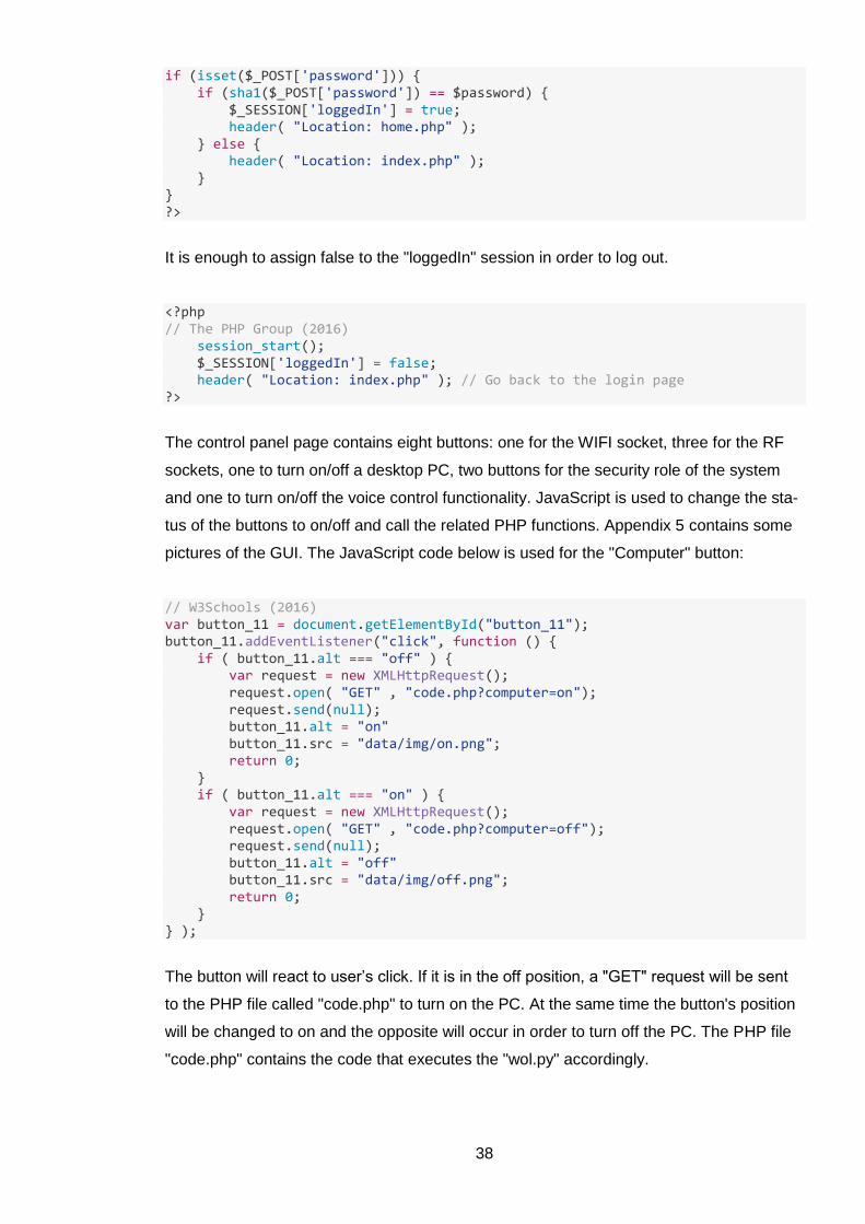
38
if (isset($_POST['password'])) { if (sha1($_POST['password']) == $password) { $_SESSION['loggedIn'] = true; header( "Location: home.php" ); } else { header( "Location: index.php" ); } } ?>
It is enough to assign false to the "loggedIn" session in order to log out.
<?php // The PHP Group (2016) session_start(); $_SESSION['loggedIn'] = false; header( "Location: index.php" ); // Go back to the login page ?>
The control panel page contains eight buttons: one for the WIFI socket, three for the RF
sockets, one to turn on/off a desktop PC, two buttons for the security role of the system
and one to turn on/off the voice control functionality. JavaScript is used to change the sta-
tus of the buttons to on/off and call the related PHP functions. Appendix 5 contains some
pictures of the GUI. The JavaScript code below is used for the "Computer" button:
// W3Schools (2016) var button_11 = document.getElementById("button_11"); button_11.addEventListener("click", function () { if ( button_11.alt === "off" ) { var request = new XMLHttpRequest(); request.open( "GET" , "code.php?computer=on"); request.send(null); button_11.alt = "on" button_11.src = "data/img/on.png"; return 0; } if ( button_11.alt === "on" ) { var request = new XMLHttpRequest(); request.open( "GET" , "code.php?computer=off"); request.send(null); button_11.alt = "off" button_11.src = "data/img/off.png"; return 0; } } );
The button will react to user’s click. If it is in the off position, a "GET" request will be sent
to the PHP file called "code.php" to turn on the PC. At the same time the button's position
will be changed to on and the opposite will occur in order to turn off the PC. The PHP file
"code.php" contains the code that executes the "wol.py" accordingly.
39
<?php // The PHP Group (2016) if (isset ($_GET["computer"])) { $computer = strip_tags($_GET["computer"]); if ($computer == "on"){ echo exec('nohup sudo python /home/pi/wol.py on > /dev/null 2>&1&'); } if ($computer == "off"){ echo exec('nohup sudo python /home/pi/wol.py off > /dev/null 2>&1&'); } } ?>
The PC's current status can be found by sending a "ping" request to its IP address, based
on the result the "Computer" button's position is determined when a user login to the con-
trol panel. The following code is copied from the control panel page:
<?php // The PHP Group (2016) function pingAddress($ip) { $pingresult = exec("ping -c 1 $ip", $outcome, $status); if (0 == $status) { return true; } else { return false; } } echo '<tr>'; echo '<td class="description">'; echo 'Computer'; echo '</td>'; echo '<td class="buttons">'; //if on if (pingAddress("10.0.0.100")) { echo ("<img id='button_11' src='data/img/on.png' alt='on'/>"); } //if off else { echo ("<img id='button_11' src='data/img/off.png' alt='off'/>"); } echo '</td>'; echo '</tr>'; ?>
For all other buttons, a similar structure is adopted. The last example of this part covers
the "Remote TEMP switch" which controls the RF socket using the home temperature.
PHP script is used to add and remove the cron entry that is covered in subchapter "Con-
trolling the sockets using home temperature and timer". The crontab is basically a file that
can be modified with the following code:
<?php // stackoverflow (2016) $output = shell_exec('crontab -l'); $cron_file = "/var/tmp/crontab.txt"
40
if ( isset ($_GET["option"]) && isset($_GET["celsius"])) { $option = strip_tags($_GET["option"]); $celsius = strip_tags($_GET["celsius"]); $contentTemp="*/1 * * * * nohup sudo python /home/pi/temp.py ".$option." ".$celsius." > /dev/null 2>&1&"; file_put_contents($cron_file, $output.$contentTemp.PHP_EOL); echo exec("crontab $cron_file"); } ?>
And to remove a cron entry, the code below examines the crontab file line by line and if a
line contains the given string it will be removed from the crontab. The following code is
added to the file "code.php":
<?php // stackoverflow (2016) $output = shell_exec('crontab -l'); $cron_file = "/var/tmp/crontab.txt" if(!empty($_GET["del"])) { foreach(preg_split("/((\r?\n)|(\r\n?))/", $output) as $line){ if (!strpos($line,$_GET["del"]) && strlen ($line)> 2) { $remove_cron = $remove_cron.$line.PHP_EOL; } } file_put_contents($cron_file, $remove_cron); echo exec("crontab $cron_file"); } ?>
It is also important to mention that the required permission must be given to the user
"www-data" by adding this line www-data ALL=(ALL)NOPASSWD: ALL to the file called
"/etc/sudoers".
In order to control other functions, for example the Bluetooth identification which is cov-
ered in the subchapter "Controlling the security system via Bluetooth", the control panel
must also be able to start a process using the PHP command echo exec('nohup sudo python
/home/pi/start_bt.py > /dev/null 2>&1&'); and to stop a process by executing the PHP script
echo exec("sudo pkill -9 -f start_bt.py");. The first command will be used when the "Bluetooth
security" button is turned on and the second command kills the process if the button is
turned off.
By now the thesis paper has covered three stages of the system development life cycle
which are requirement analysis, design and implementation. The next two chapters are
dedicated to the testing and evaluation of the presented system. The testing stage has
uncovered some of the system's performance issues which are described in details in the
related chapter.

41
5 Testing
Testing is performed to make sure that the developed system follows the listed require-
ments in the subchapter "Project questions and objectives". This chapter contains the de-
scription of the methods used to test the presented product.
It is not possible to test everything and all defects cannot be detected during the testing
phase, however, product testing must ensure that all the required features are working
properly. It is advised to start the testing during the design phase since possible errors
can cost 20 to 100 times more during operations and maintenance. (Lewis 2005, 8-10)
Although the testing chapter is almost at the end of this thesis paper it is essential to spec-
ify that the codes and the description are the results of a tested and working product. The
testing during the design has revealed some defects in the system which were fixed. For
example, the problem of receiving multiple SMSs due to the motion detection is fixed by
adding a ten minutes’ delay between text messages in the related Python script called
"motion.py".
The other discovered issue was getting random false motion alarms. The wiring is
checked first and the script is inspected for possible bugs. The next step was to adjust the
PIR sensitivity by using the trimpot on the back of the device that is shown in Figure 19.
However, it is discovered that the issue is caused by a defected PIR. The problem is
solved by replacing the PIR sensor with a new one.
Figure 19: PIR sensor
42
As stated earlier, at this stage the current DIY project is meant for the personal use and
based on this information a walkthrough test is conducted by two current users of the sys-
tem to make sure that all the components can work together as a unit.
A walkthrough serves two purposes: to find out about the activities that system user per-
forms and to see how the system will be used. The walkthrough can be conducted with
less than seven participants and can last no more than two hours. There should be a
break if more time is needed and the walkthrough will determine whether the product is
accepted as it is, accepted with recommended change or totally rejected. (Perry 2006,
213 & Lewis 2005, 513-514)
The walkthrough test revealed issues about the voice control functionality of the project. It
is estimated that on average one out of three commands must be repeated in order for the
system to react. The issue does not cause any vulnerability to the security system since
the voice control is just connected to the home automation part of the project.
The other recommendation has affected the GUI and was related to the naming of the
buttons so, instead of using numbers and letters for the buttons a more suitable naming is
adopted. The test also uncovered that sometimes the RasPi does not recognize the USB
webcam connected to it and further investigation led to solving the problem by changing
the power adapter for the RasPi to a proper one which is capable of producing 5V
2000mA DC output current.
The final method used for testing the product was through the possible real-life situations,
for example, what will happen if the residents leave the house but they have to come back
immediately to get something they forgot. The test is conducted to examine the behavior
of the Bluetooth controlling the security system. The current version of the Python script
"start_bt.py" is the result of a successful test.
The other situation considered the possibility of destroying the PIR in the case of intrusion
immediately after entering the house. Will the owner still receive the SMS notification?
The test result confirmed the success of the security system although it is possible to
damage the RasPi within 12 seconds after the PIR’s signal is received. This way the video
will not be uploaded to the cloud and the SMS notification will not be sent. So, it is rec-
ommended to keep the product somewhere hidden in the house. It is also recommended
to hide the router and secure it with a good password.
43
One of the requirements is to control the system remotely over the internet. "Port Forward-
ing" is a method that can be used for this purpose. The default port for the Apache server
is 80 but the port number can be changed by modifying the Apache's configuration. The
"Port Forwarding" can be done through the router's control panel, though the description
of the complete procedure is out of the scope of this paper. The current system's GUI is
tested to be accessible remotely from anywhere via an internet browser.
During the Christmas holidays, the decorative lights were controlled without any discov-
ered problems using the home automation feature of the product. The lights were turned
on/off at a specific time for several days. The security system was also up and running
24/7 from 6.1.2015 till 13.1.2016 during a holiday trip of residents without having any false
alarms or known errors.

44
6 Ways to improve future implementations
It is true that the current product has fulfilled the paper's requirements and the testing
chapter has successfully reviewed this fact. Appendix 6 contains some pictures of the
device that is created for this thesis work. However, there is always room for improvement
in the future implementations.
The first function which can be modified is the voice control feature of the product. The
system is using an API called Speech-To-Text (STT) that is responsible for extracting the
user's command from a recorded voice. As mentioned in the testing chapter, the function
is not 100% accurate. To fix the issue, several APIs can be used instead of one and their
outputs can be compared to get more precise results.
It is also possible to add more sensors and devices to the product in order to increase the
capability of the home automation and the security system, for example, an RF doorbell,
an RF light bulb holder and a smoke detector. Figure 20 contains some pictures of such
devices.
Figure 20: Extra sensors to improve the product
Another part which can be improved is the GUI. It is required to modify the system's code
in order to add and control new sensors and features. If developed, an administrator or
configuration area can make the process easier.
The security of the entire product needs improvement as well and to do so a complete
research about the potential security threat is expected. The Open Web Application Secu-
45
rity Project (OWASP) report which contains top 10 security risks can be utilized to improve
the product's security. The physical security risks must also be improved, for example, a
total blackout can compromise the security system since the RasPi is connected to the
main power. The easy solution for this issue is to add a power back in order to act as a
power supply for the product.
During the completion of this thesis paper, the Raspberry Pi Foundation (2015) has re-
leased a new version of the RasPi named The Raspberry Pi Zero and they call it the $5
computer. The RasPi zero is more affordable than the board used for this project (The
Raspberry Pi 2 Model B). Considering the new RasPi's price, it is cost efficient to use two
boards for this DIY project. It is better to dedicate one RasPi for the security system and
one for the home automation. If needed, the two RasPis can communicate with each other
using UDP packages or RF signals.
46
7 Conclusion
The current product is capable of controlling home devices through the RF and the WIFI
sockets. Devices like the air conditioner or the electric kettle can be turned on/off based
on the room's temperature or at a specific time. The system can be managed with voice
commands and a GUI. The product's security features are also tested and working ac-
cording to the conditions which can be found in the chapter "Project questions and objec-
tives". If a home intrusion occurs, the system notifies the homeowner after triggering the
alarm and saves a video clip of the incident to the cloud. A panic button is added to the
system in order to inform someone in case of emergency.
The RasPi was chosen to serve as the main part of the developed device based on its
abilities and features. The money cost and details for this project are shown in Appendix
1. The RasPi has proven to accomplish its purpose for this thesis work. The board is ca-
pable of handling several tasks at the same time and that feature is required for this pro-
ject.
The implementation phase gives an insight into the project development and to make the
work more understandable extra pictures and diagrams were added to the relevant chap-
ters. All the diagrams are related to this thesis work and were created during the imple-
mentation phase.
Without the testing phase in the project development lifecycle, it is very difficult to make
sure about a project's stability and issues. The testing phase for this project has discov-
ered some problems which were fixed during and after the implementation. The paper
also contains a chapter that suggests some modifications and additions for the future de-
velopments.
The thesis advisor's comments were very useful in order to find good sources and do a
better work. The advisor, Tero Karvinen, has monitored the thesis work closely and regu-
larly through an online service called GitHub. He teaches Linux and embedded systems at
HAAGA-HELIA University of Applied Sciences. Tero has published five books on the open
source platform.
The online version of this paper is available at URL: https://github.com/Ashkan-
Yaldaie/thesis.

47
References
Adafruit. 2015. URL: https://www.adafruit.com/. Accessed: 17.03.2016.
Blythe, Jeremy. 2015. URL: http://jeremyblythe.blogspot.fi/2015/06/motion-google-drive-
uploader-for-oauth.html. Accessed: 30.12.2015.
Clas ohlson. 2015. URL:
http://www.clasohlson.com/fi/b/S%C3%A4hk%C3%B6/%C3%84lykoti/Aloituspaketit. Ac-
cessed: 09.11.2015.
Dennis, Andrew. 2013. Raspberry Pi Home Automation with Arduino. Packt Publishing
Ltd.
Edney, Andrew. 2014. How to build a wireless motion sensor for your Raspberry Pi. URL:
http://connecteddigitalworld.com/2014/02/15/build-wireless-motion-sensor-raspberry-pi/.
Accessed: 22.12.2015
G4S Kotiturva. 2015. URL: http://www.kotiturva.fi/. Accessed: 11.11.2015.
Gus. 2015. Beaglebone Vs Raspberry Pi 2: Choosing The Right Board. URL:
http://pimylifeup.com/beaglebone-vs-raspberry-pi/. Accessed: 06.11.2015.
Hickson, Steven. 2015. Voice Command v2.0 for the Raspberry Pi. URL:
http://stevenhickson.blogspot.fi/2013/05/voice-command-v20-for-raspberry-pi.html. Ac-
cessed: 10.12.2015.
Hows, David & Membrey, Peter. 2012. Learn Raspberry Pi with Linux. Apress.
How-To Geek. 2006. URL: http://www.howtogeek.com/. Accessed: 17.03.2016.
HP, 2015. Internet of Things Security Study: Home Security Systems Report.
instructables. 2016. URL: http://www.instructables.com/. Accessed: 17.03.2016.
Jenson, Scott. 2014. The home automation paradox. URL:
http://radar.oreilly.com/2014/02/the-home-automation-paradox.html. Accessed:
09.11.2015.
48
Klosowski, Thorin. 2013. How to Pick the Right Electronics Board for Your DIY Project.
URL: http://lifehacker.com/how-to-pick-the-right-electronics-board-for-your-diy-pr-
742869540. Accessed: 06.11.2015.
Kyas, Othmar. 2013. How To Smart Home. Key Concept Press.
Lewis, William. 2005. Software Testing and Continuous Quality Improvement. 2nd ed.
CRC Press LLC.
Lutz, Mark. 2013. Learning Python. 5th ed. O'Reilly Media.
Maksimović, Mirjana & Vujović, Vladimir & Davidović, Nikola & Milošević, Vladimir &
Perišić, Branko. 2014. Raspberry Pi as Internet of Things hardware: Performances and
Constraints. ResearchGate.
Maxim Integrated. 2008. DS18B20 Programmable Resolution 1-Wire Digital Thermome-
ter.
Netcraft, 2015. Web Server Survey. URL:
http://news.netcraft.com/archives/category/most-popular/. Accessed: 07.12.2015.
Ninja Blocks, 2015. URL: https://ninjablocks.com/. Accessed: 17.12.2015.
Norris, Donald. 2014. Raspberry Pi Projects for the Evil Genius. McGraw-Hill Education.
Perry, William. 2006. Effective Methods for Software Testing. 3rd ed. Wiley Publishing,
Inc.
Raspberry Pi Foundation. 2015. URL: https://www.raspberrypi.org/. Accessed:
26.11.2015.
Richardson, Matt & Wallace, Shawn. 2013. Getting Started with Raspberry Pi. O'Reilly
Media.
Schmidt, Maik. 2014. Raspberry Pi: A Quick-Start Guide. 2nd ed. Pragmatic Bookshelf.
49
Securitas 24Koti. 2015. URL: https://www.securitas.com/fi/fi/turvallisuuspalvelut/kodin-
turvallisuuspalvelut/24koti/. Accessed: 06.12.2015.
stackoverflow. 2016. Use PHP to create, edit and delete crontab jobs. URL:
http://stackoverflow.com/questions/4421020/use-php-to-create-edit-and-delete-crontab-
jobs/4421284. Accessed: 17.03.2016.
Štikonas, Andrius. 2015. Reverse engineering Orvibo S20 socket. URL:
https://stikonas.eu/wordpress/2015/02/24/reverse-engineering-orvibo-s20-socket/. Ac-
cessed: 17.03.2016.
The PHP Group. 2016. URL: http://php.net/. Accessed: 17.03.2016.
Velte, Toby & Elsenpeter, Robert. 2003. Build Your Own Smart Home. The McGraw-Hill
Companies.
VideoLAN's Wiki. 2015. Streaming HowTo/Command Line Examples. URL:
https://wiki.videolan.org/Documentation:Streaming_HowTo/Command_Line_Examples/.
Accessed: 17.03.2016.
Upton, Eben & Halfacree, Gareth. 2014. Raspberry Pi User Guide. 2nd ed. John Wiley &
Sons Ltd.
W3Schools. 2016. JavaScript Tutorial. URL: http://www.w3schools.com/js/default.asp.
Accessed: 17.03.2016.

50
Appendices
Appendix 1. Devices used for this project and the purchase information
Shop Link
eBay www.ebay.com
DNA www.dna.fi
K-market www.k-market.fi
Eldorado www.eldorado.ru
Item Price Purchased From
Raspberry Pi 2 - Model B €36.90 eBay
Kingston 16GB MicroSD €6.98 eBay
DS18B20 Temperature Sensor Module €2.07 eBay
ORVIBO S20 WIFI Power Socket €20.00 eBay
Huawei E303 3G Modem €20.53 eBay
4 Channel RF Remote Control Kit €2.38 eBay
HC-SR501 PIR Motion Sensor €0.91 eBay
Mixed Resistors, 100 Pieces €1.81 eBay
50 Pieces, 2N2222 NPN Transistor €0.92 eBay
Breadboard and Jumper Cable Wires €2.89 eBay
433MHz RF Transmitter And Receiver Kit €1.09 eBay
Push Button €0.69 eBay
Bluetooth Dongle €3.63 eBay
USB Hub With A Power Adapter €5.84 eBay
Power Adapter For Raspberry Pi €4.05 eBay
RF Remote Control Power Socket Set €16 eBay
DNA Super Prepaid €4.90 DNA
9V Battery €1.50 K-market
Logitech C170 Webcam €15.95 Eldorado
Computer Speaker €5.50 Eldorado

51
Appendix 2. Table of GPIO pins and their numbers (wiringPi, BCM, GPIO and physical pin numbers)

52
Appendix 3. The bash script used to control the sockets
#!/bin/bash #sockets.sh v2.00, Štikonas (2015) #WIFI socket's IP address 10.0.0.104 echo '6864001e636c<MAC>202020202020<Reverse-MAC>202020202020' | xxd -r -p \ | nc -u -w2 -p '10000' '10.0.0.104' '10000' | xxd -r if [ "$1" = "1" ] && [ "$2" = "on" ]; then echo '686400176463<MAC>2020202020200000000001' | xxd -r -p \ | nc -n -4u -w1 '10.0.0.104' '10000' elif [ "$1" = "1" ] && [ "$2" = "off" ]; then echo '686400176463<MAC>2020202020200000000000' | xxd -r -p \ | nc -n -4u -w1 '10.0.0.104' '10000' elif [ "$1" = "2" ] && [ "$2" = "on" ]; then sudo /home/pi/433Utils/RPi_utils/codesend 5592332 elif [ "$1" = "2" ] && [ "$2" = "off" ]; then sudo /home/pi/433Utils/RPi_utils/codesend 5592328 elif [ "$1" = "3" ] && [ "$2" = "on" ]; then sudo /home/pi/433Utils/RPi_utils/codesend 5592363 elif [ "$1" = "3" ] && [ "$2" = "off" ]; then sudo /home/pi/433Utils/RPi_utils/codesend 5592372 elif [ "$1" = "4" ] && [ "$2" = "on" ]; then sudo /home/pi/433Utils/RPi_utils/codesend 5592383 elif [ "$1" = "4" ] && [ "$2" = "off" ]; then sudo /home/pi/433Utils/RPi_utils/codesend 5592392 else echo 'Status of the WIFI socket:' echo '6864001e636c<MAC>202020202020<Reverse-MAC>202020202020' | xxd -r -p \ | nc -u -w2 -p '10000' '10.0.0.104' '10000' | xxd -p | cut -c47-49 fi
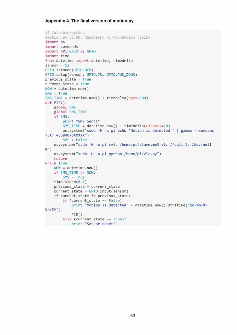
53
Appendix 4. The final version of motion.py
#! /usr/bin/python #motion.py v2.50, Raspberry Pi Foundation (2015) import os import commands import RPi.GPIO as GPIO import time from datetime import datetime, timedelta sensor = 12 GPIO.setmode(GPIO.BCM) GPIO.setup(sensor, GPIO.IN, GPIO.PUD_DOWN) previous_state = True current_state = True NOW = datetime.now() SMS = True SMS_TIME = datetime.now() + timedelta(days=300) def PIR(): global SMS global SMS_TIME if SMS: print "SMS Sent!" SMS_TIME = datetime.now() + timedelta(minutes=10) os.system("sudo -H -u pi echo 'Motion is detected!' | gammu --sendsms TEXT +3584076XXXXX") SMS = False os.system("sudo -H -u pi cvlc /home/pi/alarm.mp3 vlc://quit 2> /dev/null &") os.system("sudo -H -u pi python /home/pi/vlc.py") return while True: NOW = datetime.now() if SMS_TIME <= NOW: SMS = True time.sleep(0.1) previous_state = current_state current_state = GPIO.input(sensor) if current_state != previous_state: if (current_state == False): print "Motion is detected" + datetime.now().strftime("%d-%m-%Y %H:%M") PIR() elif (current_state == True): print "Sensor reset!"
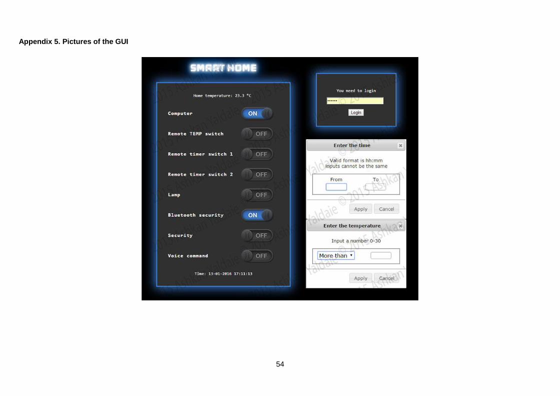
54
Appendix 5. Pictures of the GUI

55
Appendix 6. Pictures of the device