HMI INSTRUCTIONS | BRONCOLOR HMI F1600 HMI 800.1600 Before use Please read all the information...
16
HMI F1600 | 800.1600 Operating instructions | Bedienungsanleitung | Mode d‘emploi
Transcript of HMI INSTRUCTIONS | BRONCOLOR HMI F1600 HMI 800.1600 Before use Please read all the information...

Creative lighting, precision, inspiration, style and emotion – even in the age of digital photography, none of these facets have lost in importance. broncolor offers workshops of 2 and 3 days. Are you interested? You can apply online on our website www.bron.ch under broncolor / Lighting / Workshops
Kreative Lichtführung, Präzision, Inspiration, Styling und Emotionen – auch im Zeitalter der digitalen Fotografie haben sich die Stichworte nicht geändert. broncolor bietet verschiedene Workshops von 2- oder 3-tägiger Dauer an. Sind Sie interessiert? Sie können sich Online anmelden auf unsere Website www.bron.ch unter broncolor / Lighting / Workshops
Utilisation créative de la lumière, précision, inspiration, styling et émotions – ces notions fondamentales ont gardé toute leur importance à l’ère de la photographie numérique. broncolor propose différents workshops de 2 ou 3 jours. Etes-vous intéressé? Vous pouvez vous inscrire en ligne sur notre site internet www.bron.ch, sous la rubrique broncolor / Lighting / Workshops
BRONCOLOR LIGHTING COURSES
BRONCOLOR LICHTSCHULUNG
STAGE DE FORMATION À L‘ÉCLAIRAGE BRONCOLOR
Bron Elektronik AGCH-4123 Allschwil 1 / Switzerlandwww.bron.ch
|| U
rs R
eche
r, Sw
itzer
land
BA
108.
00 |
Pri
nted
in G
erm
any
02 /
15
HMI F1600 | 800.1600
Operating instructions | Bedienungsanleitung | Mode d‘emploi

|| S
andr
o B
äble
r, Sw
itzer
land
|| U
rs R
eche
r / m
odel
: Deb
orah
Fre
y, G
erm
any

OPERATING INSTRUCTIONS | BRONCOLOR HMI F1600 HMI 800.1600
Before usePlease read all the information contained in these operating instructions carefully. They contain important instructions for use, safety and maintenance of the appliance. Keep these operating instructions in a safe place and pass them on to further users if necessary. Observe the safety instructions.
Contents Page
Attention! Important safety instructions – Read carefully before starting up! 6
1. Starting up 7
2. Fitting or changing a bulb 8
3. Mounting and removing reflectors and adapters 8
4. Fitting and removing accessories 8
5. Focusing 9
6. Operating the lamp with a Para 9
7. Operating modes 9
8. Display on ballast unit 10
9. Protective circuits in the ballast unit 10
10. Fault diagnosis table 11
11. Operating broncolor ballast units from a motor-generator set 11
12. Controls and display elements ballast unit HMI 800.1600 12
13. Technical data, ballast unit HMI 800.1600 12
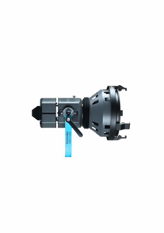
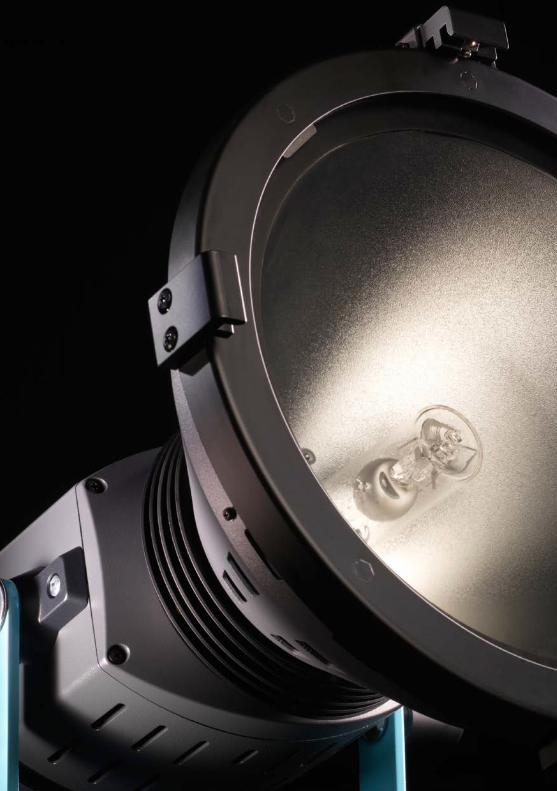
14. Controls and display elements, lamp HMI F1600 14
15. Technical data, lamp HMI F1600 16
16. Order numbers for spare parts and accessories 16
17. Environmental protection information 16
6
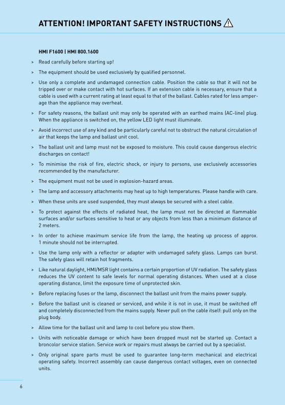
ATTENTION! IMPORTANT SAFETY INSTRUCTIONS
HMI F1600 | HMI 800.1600
> Read carefully before starting up!
> The equipment should be used exclusively by qualified personnel.
> Use only a complete and undamaged connection cable. Position the cable so that it will not be tripped over or make contact with hot surfaces. If an extension cable is necessary, ensure that a cable is used with a current rating at least equal to that of the ballast. Cables rated for less amper-age than the appliance may overheat.
> For safety reasons, the ballast unit may only be operated with an earthed mains (AC-line) plug. When the appliance is switched on, the yellow LED light must illuminate.
> Avoid incorrect use of any kind and be particularly careful not to obstruct the natural circulation of air that keeps the lamp and ballast unit cool.
> The ballast unit and lamp must not be exposed to moisture. This could cause dangerous electric discharges on contact!
> To minimise the risk of fire, electric shock, or injury to persons, use exclusively accessories recommended by the manufacturer.
> The equipment must not be used in explosion-hazard areas.
> The lamp and accessory attachments may heat up to high temperatures. Please handle with care.
> When these units are used suspended, they must always be secured with a steel cable.
> To protect against the effects of radiated heat, the lamp must not be directed at flammable surfaces and/or surfaces sensitive to heat or any objects from less than a minimum distance of 2 meters.
> In order to achieve maximum service life from the lamp, the heating up process of approx. 1 minute should not be interrupted.
> Use the lamp only with a reflector or adapter with undamaged safety glass. Lamps can burst. The safety glass will retain hot fragments.
> Like natural daylight, HMI/MSR light contains a certain proportion of UV radiation. The safety glass reduces the UV content to safe levels for normal operating distances. When used at a close operating distance, limit the exposure time of unprotected skin.
> Before replacing fuses or the lamp, disconnect the ballast unit from the mains power supply.
> Before the ballast unit is cleaned or serviced, and while it is not in use, it must be switched off and completely disconnected from the mains supply. Never pull on the cable itself: pull only on the plug body.
> Allow time for the ballast unit and lamp to cool before you stow them.
> Units with noticeable damage or which have been dropped must not be started up. Contact a broncolor service station. Service work or repairs must always be carried out by a specialist.
> Only original spare parts must be used to guarantee long-term mechanical and electrical operating safety. Incorrect assembly can cause dangerous contact voltages, even on connected units.

7
1. STARTING UP
The ballast unit HMI 800.1600 is a flicker-free electronic ballast units which are made for mains voltages from 90 V to 265 V. They adjust automatically to the mains (AC-line) voltage applied.The unit is suitable for operation with hot-restrike (HR) lamps. This means that the lamp may be switched on again at any time while hot, making waiting time unnecessary. For safety reasons, the high ignition voltages required for this purpose call for a faultless earth conductor. For this reason the unit must only be connected to a power supply with an earthed mains plug. Correct functioning of the earth conductor is indicated by the control lamp (3).
Step 1Fit a compatible bulb to the lamp (see Section 2: Fitting or changing a bulb) and a reflector, an adapter for a Softbox or Para (see Section 3: Mounting and removing reflectors and adapters). The lamp is equipped with an integral safety switch (17), and can only be operated when a reflector or an adapter is mounted. When it is used with an adapter, the focusing wheel (11) must be turned to the “Bare Bulb” position (bulb as far forwards as it will go) so that the safety switch is actuated and the bulb can be fired.
Step 2Connect the lamp to the ballast unit, and the ballast unit to the earthed mains supply. Switch on the main switch (2) and check whether the earth control LED (3) illuminates. If this is not the case, for safety reasons disconnect the ballast unit immediately from the mains and check the earth conductor.
Step 3Operate switch (9) on the lamp and press button (4) on the ballast unit. The bulb fires and starts operating. By operating the switch (9) on the lamp or on the ballast unit (4), the light can be switched off again.The ballast unit has an automatic warming-up circuit, which heats the bulb quickly to its operating temperature. Except in an emergency avoid switching off the unit during the warming-up phase, because this shortens the life of the bulb. The optimum colour temperature is reached after about one minute. Should the bulb fail to trigger, the ballast unit will switch off the ignition sequence after 2 seconds, and button (4) on the ballast unit blinks (see Section 7). To make another attempt to start, press the button (4) on the ballast unit or (9) on the lamp. To protect the igniter circuit, this is blocked for 30 seconds after about ten attempts at ignition. Afterwards further ignition attempts are pos-sible. Take care that the ventilation slots are not obstructed on either the ballast unit or the lamp.
Step 4The output regulator (8) on the ballast unit can be used to set the desired light output (setting range 50 % – 100 %). When setting the output, it is important to remember that, depending on the bulb used, the colour temperature can change slightly with the output. When the bulb is switched on, the output is automatically set to the maximum so that the bulb heats up as quickly as pos-sible. The duration of this depends on the bulb temperature when it is switched on, and is likely to be between 5 and 60 seconds. At the end of this period, the unit adjusts automatically to the setting of regulator (8).
8
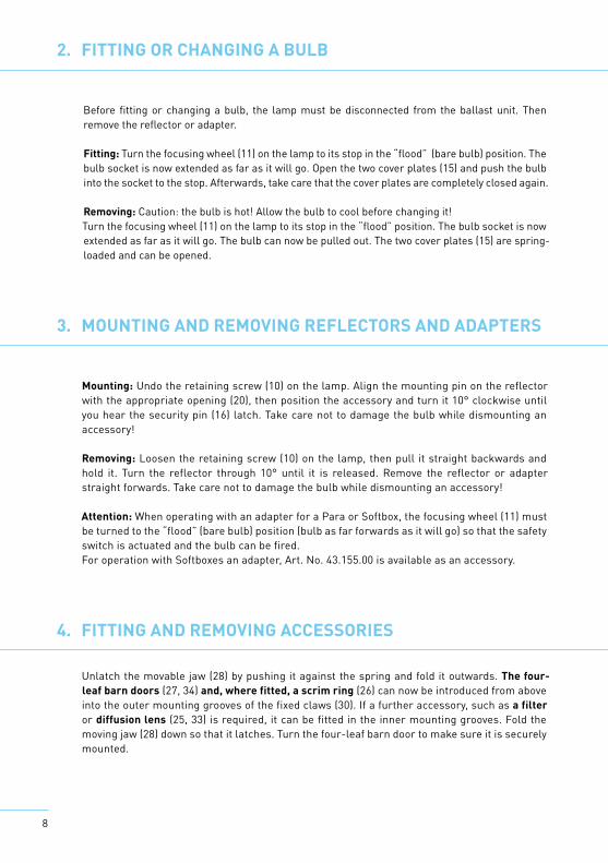
2. FITTING OR CHANGING A BULB
Before fitting or changing a bulb, the lamp must be disconnected from the ballast unit. Then remove the reflector or adapter.
Fitting: Turn the focusing wheel (11) on the lamp to its stop in the “flood” (bare bulb) position. The bulb socket is now extended as far as it will go. Open the two cover plates (15) and push the bulb into the socket to the stop. Afterwards, take care that the cover plates are completely closed again.
Removing: Caution: the bulb is hot! Allow the bulb to cool before changing it! Turn the focusing wheel (11) on the lamp to its stop in the “flood” position. The bulb socket is now extended as far as it will go. The bulb can now be pulled out. The two cover plates (15) are spring-loaded and can be opened.
3. MOUNTING AND REMOVING REFLECTORS AND ADAPTERS
Mounting: Undo the retaining screw (10) on the lamp. Align the mounting pin on the reflector with the appropriate opening (20), then position the accessory and turn it 10° clockwise until you hear the security pin (16) latch. Take care not to damage the bulb while dismounting an accessory!
Removing: Loosen the retaining screw (10) on the lamp, then pull it straight backwards and hold it. Turn the reflector through 10° until it is released. Remove the reflector or adapter straight forwards. Take care not to damage the bulb while dismounting an accessory!
Attention: When operating with an adapter for a Para or Softbox, the focusing wheel (11) must be turned to the “flood” (bare bulb) position (bulb as far forwards as it will go) so that the safety switch is actuated and the bulb can be fired.For operation with Softboxes an adapter, Art. No. 43.155.00 is available as an accessory.
4. FITTING AND REMOVING ACCESSORIES
Unlatch the movable jaw (28) by pushing it against the spring and fold it outwards. The four-leaf barn doors (27, 34) and, where fitted, a scrim ring (26) can now be introduced from above into the outer mounting grooves of the fixed claws (30). If a further accessory, such as a filter or diffusion lens (25, 33) is required, it can be fitted in the inner mounting grooves. Fold the moving jaw (28) down so that it latches. Turn the four-leaf barn door to make sure it is securely mounted.
9
5. FOCUSING
The degree of focusing can be adjusted using the focusing wheel (11) on the rear face of the lamp. The adjustment function is indicated with “flood” (bare bulb) and “spot” markings. When the lamp is operated with an Open Face or a PAR reflector and a Fresnel lens fitted, then the entire focus-ing range can be used.
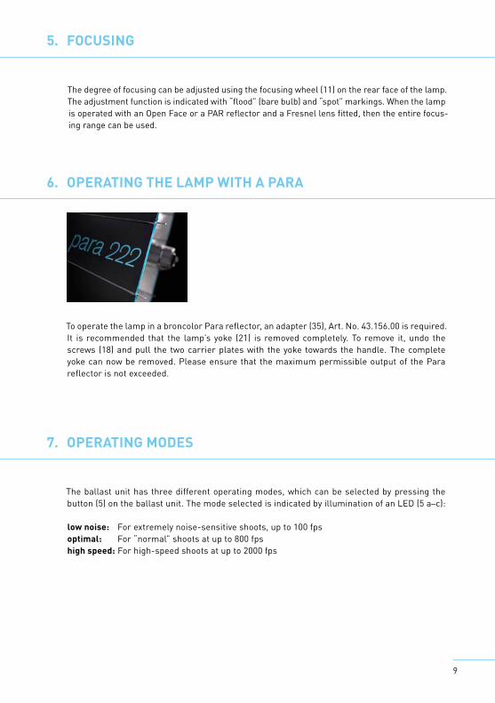
6. OPERATING THE LAMP WITH A PARA
To operate the lamp in a broncolor Para reflector, an adapter (35), Art. No. 43.156.00 is required. It is recommended that the lamp’s yoke (21) is removed completely. To remove it, undo the screws (18) and pull the two carrier plates with the yoke towards the handle. The complete yoke can now be removed. Please ensure that the maximum permissible output of the Para reflector is not exceeded.
7. OPERATING MODES
The ballast unit has three different operating modes, which can be selected by pressing the button (5) on the ballast unit. The mode selected is indicated by illumination of an LED (5 a–c):
low noise: For extremely noise-sensitive shoots, up to 100 fpsoptimal: For “normal” shoots at up to 800 fpshigh speed: For high-speed shoots at up to 2000 fps
10
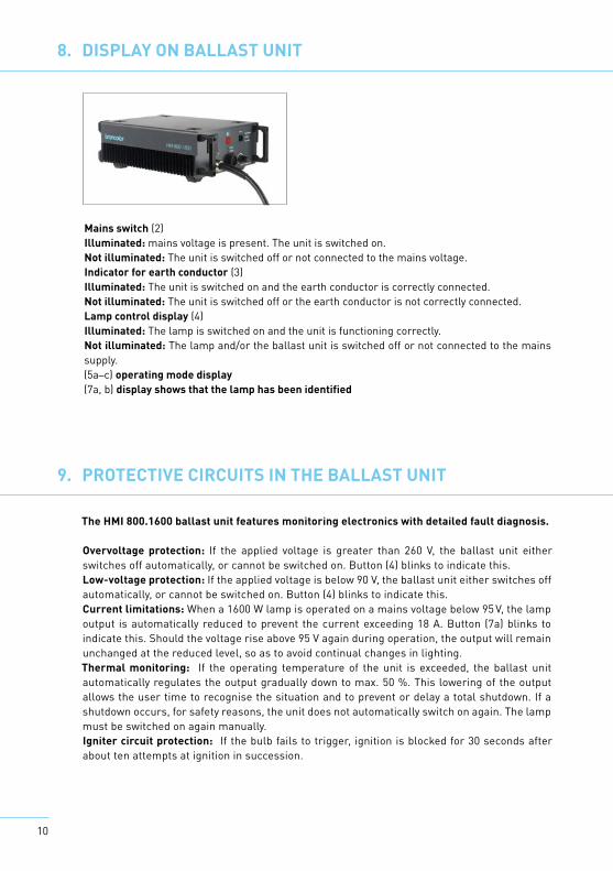
8. DISPLAY ON BALLAST UNIT
Mains switch (2)Illuminated: mains voltage is present. The unit is switched on.Not illuminated: The unit is switched off or not connected to the mains voltage.Indicator for earth conductor (3)Illuminated: The unit is switched on and the earth conductor is correctly connected.Not illuminated: The unit is switched off or the earth conductor is not correctly connected.Lamp control display (4)Illuminated: The lamp is switched on and the unit is functioning correctly. Not illuminated: The lamp and/or the ballast unit is switched off or not connected to the mains supply.(5a–c) operating mode display(7a, b) display shows that the lamp has been identified
The HMI 800.1600 ballast unit features monitoring electronics with detailed fault diagnosis.
Overvoltage protection: If the applied voltage is greater than 260 V, the ballast unit either switches off automatically, or cannot be switched on. Button (4) blinks to indicate this.Low-voltage protection: If the applied voltage is below 90 V, the ballast unit either switches off automatically, or cannot be switched on. Button (4) blinks to indicate this.Current limitations: When a 1600 W lamp is operated on a mains voltage below 95 V, the lamp output is automatically reduced to prevent the current exceeding 18 A. Button (7a) blinks to indicate this. Should the voltage rise above 95 V again during operation, the output will remain unchanged at the reduced level, so as to avoid continual changes in lighting. Thermal monitoring: If the operating temperature of the unit is exceeded, the ballast unit automatically regulates the output gradually down to max. 50 %. This lowering of the output allows the user time to recognise the situation and to prevent or delay a total shutdown. If a shutdown occurs, for safety reasons, the unit does not automatically switch on again. The lamp must be switched on again manually.Igniter circuit protection: If the bulb fails to trigger, ignition is blocked for 30 seconds after about ten attempts at ignition in succession.
9. PROTECTIVE CIRCUITS IN THE BALLAST UNIT
11
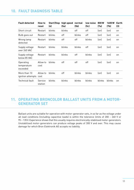
Fault detected How to reset
Start/Stop(4)
high speed(5a)
normal(5b)
low noise(5c)
800 W (7a)
1600 W(7b)
Earth(3)
Short circuit Restart blinks blinks off off (on) (on) on
Bulb goes out Restart blinks off blinks off (on) (on) on
Wrong lamp detected
Restart blinks off off blinks (on) (on) on
Supply voltage over 265 VAC
Restart blinks blinks blinks off (on) (on) on
Supply voltage below 85 VAC
Restart blinks blinks off blinks (on) (on) on
Operating temperature exceeded
Allow to cool
blinks off off off (on) (on) on
More than 10 ignition attempts
Allow to cool
blinks off blinks blinks (on) (on) on
Technical fault Service station
blinks blinks blinks blinks blinks blinks on
10. FAULT DIAGNOSIS TABLE
Ballast units are suitable for operation with motor-generator sets, in so far as the voltage under all load conditions (including capacitive loads) is within the tolerance limits of 200 – 260 V or 95 – 135 V. Experience shows that this usually requires electronically-stabilised motor-generators. Unstabilised motor-generators can produce voltage peaks of 300 V and over. This may cause damage for which Bron Elektronik AG accepts no liability.
11. OPERATING BRONCOLOR BALLAST UNITS FROM A MOTOR- GENERATOR SET 9. PROTECTIVE CIRCUITS IN THE BALLAST UNIT

12
12. CONTROLS AND DISPLAY ELEMENTS BALLAST UNIT HMI 800.1600
1 Grip2 Main switch 0/I with integral fuse3 Earth conductor indicator4 Button, lamp On/Off5 Button for selecting operating mode5a–c Indicators for selected operating mode6 Mains cable7 Lamp plug socket 7a–b Indicators show which lamp has been identified8 Rotary knob for adjusting output (dimmer)
13. TECHNICAL DATA, BALLAST UNIT HMI 800.1600
Supply power rating 1800 VAMains voltage 90 – 265 VMains frequency 50/60 Hz Current draw 20 A (90 VAC), 15 A (120 VAC), 8 A (230 VAC)Power factor 99 % at 110 V / 95 % at 230 VLamp frequency square-wave 50, 400, 1000 HzRegulation zone 50 – 100 %Lamp detection automaticStart-up characteristics cold start and hot restrike capabilityDimensions (lxbxh) 360 x 240 x 120 mm (142 x 94 x 47")Weight 6.9 kg (15.2 lbs)

13
14
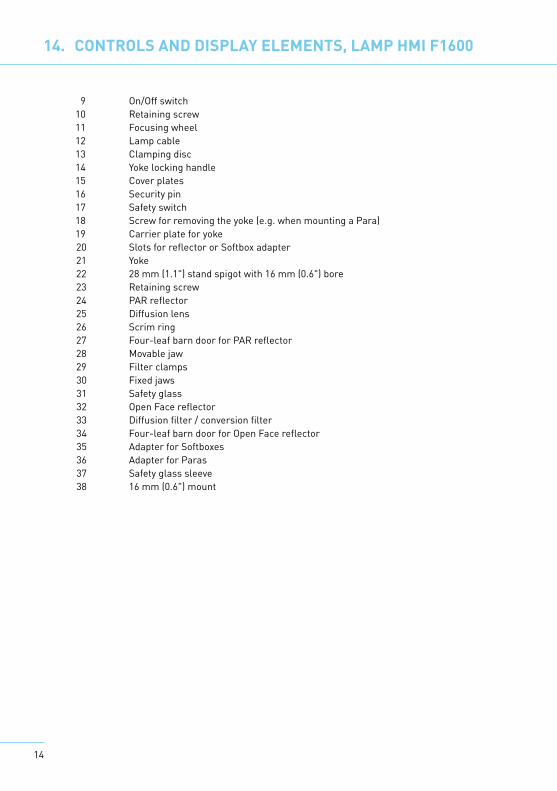
14. CONTROLS AND DISPLAY ELEMENTS, LAMP HMI F1600
9 On/Off switch 10 Retaining screw11 Focusing wheel12 Lamp cable13 Clamping disc14 Yoke locking handle15 Cover plates16 Security pin 17 Safety switch18 Screw for removing the yoke (e.g. when mounting a Para)19 Carrier plate for yoke20 Slots for reflector or Softbox adapter21 Yoke22 28 mm (1.1") stand spigot with 16 mm (0.6") bore23 Retaining screw24 PAR reflector25 Diffusion lens26 Scrim ring27 Four-leaf barn door for PAR reflector28 Movable jaw29 Filter clamps30 Fixed jaws31 Safety glass32 Open Face reflector33 Diffusion filter / conversion filter34 Four-leaf barn door for Open Face reflector35 Adapter for Softboxes36 Adapter for Paras37 Safety glass sleeve38 16 mm (0.6") mount

15
16
15. TECHNICAL DATA, LAMP HMI F1600
Output 1600 W Bulb socket G22Focusing range, Open Face reflector 19° – 58° Dimensions (lxbxh) 250 x 302 x 145/408 mm (98 x 119 x 57/161")Weight 4.3 kg (9.5 lbs)
16. ORDER NUMBERS FOR SPARE PARTS AND ACCESSORIES
Ballast unit HMI 1600 41.104.XXLamp F1600 42.108.00Open Face reflector 43.150.00Four-leaf barn door for Open Face reflector 43.151.00Diffusion filter for Open Face reflector 43.152.00Conversion filter for PAR reflector 43.153.00PAR reflector 43.140.00Four-leaf barn door for Open Face reflector 41.141.00Scrim ring 43.139.00PAR lens set (4 off) 43.144.00PAR lens NSP 43.145.00PAR lens MFL 43.146.00PAR lens WFL 43.147.00PAR lens VWFL 43.148.00Fresnel lens 43.149.00Bag for 5 filters or lenses 43.138.001600 W bulb G.E. CSR1600 SE/HR/UVC 44.107.001600 W bulb Sylvania BA1600 SE/HR/UVC 44.108.00Lamp cable 7.5 m 44.202.00Lamp cable 10 m 44.203.00Lamp cable 20 m 44.204.00Adapter for Softboxes 43.155.00Adapter for Paras 43.156.00Carrying case with wheels for complete kits 46.101.00Carrying case for Para Kit 46.102.00
17. ENVIRONMENTAL PROTECTION INFORMATION
At the end of its useful life, this product may not be disposed of as normal household waste, but should be taken to a collection point for the recy-cling of electrical and electronic appliances. The materials are recyclable according to their markings. By re-use, recycling, or other form of using old appliances you are making an important contribution to the protection of our environment. Please ask your sales partner or local authorities for the appropriate disposal point.