Hilti X-HVB shear connector · Hilti X-HVB shear connector ... shear connectors fixed over the...
15
X-HVB Hilti (Gt. Britain) Limited, 1 Trafford Wharf Road, Trafford Park, Manchester M17 1BY Telephone: 0800 886 100 Hilti X-HVB shear connector The product data is taken from the Hilti Direct Fastening Technology Manual Edition August 2011 For further details including details of product European Technical Approvals, Guidance on product selection and detailed design assistance please contact Hilti (Gt Britain) Ltd Technical Advisory Service. Hilti (Gt Britain) Ltd TECHNICAL ADVISORY SERVICE Telephone 0161 886 1144 Email [email protected] Quality Management Approvals ISO 9001: 2008 Quality Management System Certified by: The Swiss Association for Quality and Management Systems. Registration No: 12455 Valid until 30th June 2013 Scope No: 18, Machinery and Equipment. Note: Under our accreditation with SQS the scope of accreditation is not contained within an appendix but is stated as Scope 18 on the SQS Certificate. Scope No. 18 is Machinery and Equipment.”
Transcript of Hilti X-HVB shear connector · Hilti X-HVB shear connector ... shear connectors fixed over the...
X-HVB
Hilti (Gt. Britain) Limited,
1 Trafford Wharf Road, Trafford Park, Manchester M17 1BY
Telephone:
0800 886 100
Hilti X-HVB shear connector
The product data is taken from the Hilti Direct Fastening Technology Manual
Edition August 2011
For further details including details of product European Technical Approvals, Guidance on product selection and detailed design assistance
please contact Hilti (Gt Britain) Ltd Technical Advisory Service.
Hilti (Gt Britain) Ltd
TECHNICAL ADVISORY SERVICE
Telephone 0161 886 1144
Email [email protected]
Quality Management Approvals ISO 9001: 2008 Quality Management System Certified by: The Swiss Association for Quality and Management Systems. Registration No: 12455 Valid until 30th June 2013 Scope No: 18, Machinery and Equipment. Note: Under our accreditation with SQS the scope of accreditation is not contained within an appendix but is stated as Scope 18 on the SQS Certificate. Scope No. 18 is Machinery and Equipment.”
X-HVB
Hilti (Gt. Britain) Limited,
1 Trafford Wharf Road, Trafford Park, Manchester M17 1BY
Telephone:
0800 886 100
Important notice
1. Construction materials and conditions vary on different sites. If it is suspected that the base material has insufficient strength to achieve a suitable fastening, contact the Hilti Technical Advisory Service. 2. The information and recommendations given herein are based on the principles, formulae and safety factors set out in the Hilti technical instructions, the operating manuals, the setting instructions, the installation manuals and other data sheets that are believed to be correct at the time of writing. The data and values are based on the respective average values obtained from tests under laboratory or other controlled conditions. It is the users responsibility to use the data given in the light of conditions on site and taking into account the intended use of the products concerned. The user has to check the listed prerequisites and criteria conform with the conditions actually existing on the job-site. Whilst Hilti can give general guidance and advice, the nature of Hilti products means that the ultimate responsibility for selecting the right product for a particular application must lie with the customer. 3. All products must be used, handled and applied strictly in accordance with all current instructions for use published by Hilti, i.e. technical instructions, operating manuals, setting instructions, installation manuals and others. 4. All products are supplied and advice is given subject to the Hilti terms of business. 5. Hilti´s policy is one of continuous development. We therefore reserve the right to alter specifications, etc. without notice. 6. The given mean ultimate loads and characteristic data in the Anchor Fastening Technology Manual reflect actual test results and are thus valid only for the indicated test conditions. Due to variations in local base materials, on-site testing is required to determine performance at any specific site. 7. Hilti is not obligated for direct, indirect, incidental or consequential damages, losses or expenses in connection with, or by reason of, the use of, or inability to use the products for any purpose. Implied warranties of merchantability or fitness for a particular purpose are specifically excluded. Hilti Corporation FL-9494 Schaan Principality of Liechtenstein www.hilti.com
X-HVB
Hilti (Gt. Britain) Limited,
1 Trafford Wharf Road, Trafford Park, Manchester M17 1BY
Telephone:
0800 886 100
The Hilti X-HVB shear connector
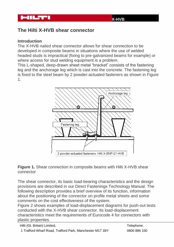
Introduction The X-HVB nailed shear connector allows for shear connection to be developed in composite beams in situations where the use of welded headed studs is impractical (fixing to pre-galvanized beams for example) or where access for stud welding equipment is a problem. This L-shaped, deep-drawn sheet metal “bracket” consists of the fastening leg and the anchorage leg which is cast into the concrete. The fastening leg is fixed to the steel beam by 2 powder-actuated fasteners as shown in Figure 1.
Figure 1. Shear connection in composite beams with Hilti X-HVB shear connector
The shear connector, its basic load-bearing characteristics and the design provisions are described in our Direct Fastenings Technology Manual. The following description provides a brief overview of its function, information about the positioning of the connector on profile metal sheets and some comments on the cost effectiveness of the system. Figure 2 shows examples of load-displacement diagrams for push-out tests conducted with the X-HVB shear connector. Its load-displacement characteristics meet the requirements of Eurocode 4 for connectors with plastic properties.
X-HVB
Hilti (Gt. Britain) Limited,
1 Trafford Wharf Road, Trafford Park, Manchester M17 1BY
Telephone:
0800 886 100
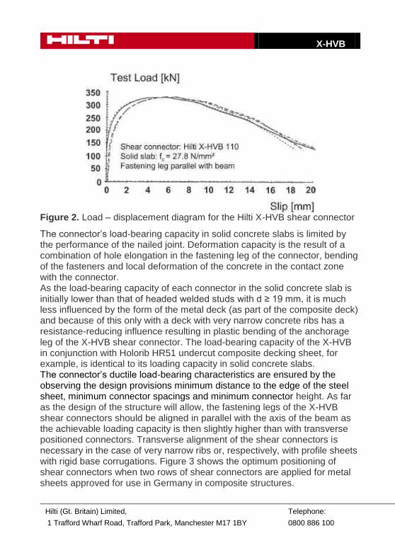
Figure 2. Load – displacement diagram for the Hilti X-HVB shear connector
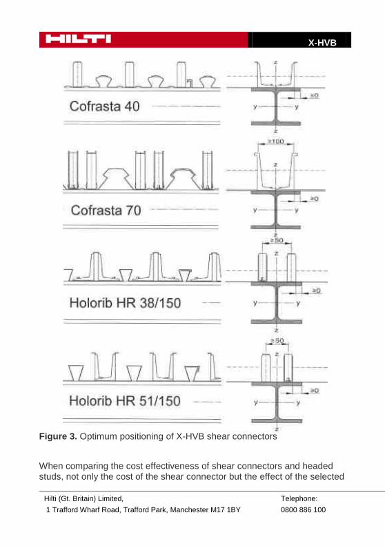
The connector’s load-bearing capacity in solid concrete slabs is limited by the performance of the nailed joint. Deformation capacity is the result of a combination of hole elongation in the fastening leg of the connector, bending of the fasteners and local deformation of the concrete in the contact zone with the connector. As the load-bearing capacity of each connector in the solid concrete slab is initially lower than that of headed welded studs with d ≥ 19 mm, it is much less influenced by the form of the metal deck (as part of the composite deck) and because of this only with a deck with very narrow concrete ribs has a resistance-reducing influence resulting in plastic bending of the anchorage leg of the X-HVB shear connector. The load-bearing capacity of the X-HVB in conjunction with Holorib HR51 undercut composite decking sheet, for example, is identical to its loading capacity in solid concrete slabs. The connector’s ductile load-bearing characteristics are ensured by the observing the design provisions minimum distance to the edge of the steel sheet, minimum connector spacings and minimum connector height. As far as the design of the structure will allow, the fastening legs of the X-HVB shear connectors should be aligned in parallel with the axis of the beam as the achievable loading capacity is then slightly higher than with transverse positioned connectors. Transverse alignment of the shear connectors is necessary in the case of very narrow ribs or, respectively, with profile sheets with rigid base corrugations. Figure 3 shows the optimum positioning of shear connectors when two rows of shear connectors are applied for metal sheets approved for use in Germany in composite structures.
X-HVB
Hilti (Gt. Britain) Limited,
1 Trafford Wharf Road, Trafford Park, Manchester M17 1BY
Telephone:
0800 886 100
Figure 3. Optimum positioning of X-HVB shear connectors
When comparing the cost effectiveness of shear connectors and headed studs, not only the cost of the shear connector but the effect of the selected
X-HVB
Hilti (Gt. Britain) Limited,
1 Trafford Wharf Road, Trafford Park, Manchester M17 1BY
Telephone:
0800 886 100
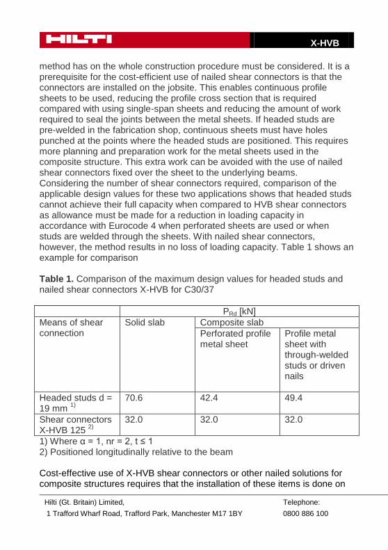
method has on the whole construction procedure must be considered. It is a prerequisite for the cost-efficient use of nailed shear connectors is that the connectors are installed on the jobsite. This enables continuous profile sheets to be used, reducing the profile cross section that is required compared with using single-span sheets and reducing the amount of work required to seal the joints between the metal sheets. If headed studs are pre-welded in the fabrication shop, continuous sheets must have holes punched at the points where the headed studs are positioned. This requires more planning and preparation work for the metal sheets used in the composite structure. This extra work can be avoided with the use of nailed shear connectors fixed over the sheet to the underlying beams. Considering the number of shear connectors required, comparison of the applicable design values for these two applications shows that headed studs cannot achieve their full capacity when compared to HVB shear connectors as allowance must be made for a reduction in loading capacity in accordance with Eurocode 4 when perforated sheets are used or when studs are welded through the sheets. With nailed shear connectors, however, the method results in no loss of loading capacity. Table 1 shows an example for comparison Table 1. Comparison of the maximum design values for headed studs and nailed shear connectors X-HVB for C30/37
PRd [kN]
Means of shear connection
Solid slab Composite slab
Perforated profile metal sheet
Profile metal sheet with through-welded studs or driven nails
Headed studs d = 19 mm
1)
70.6
42.4 49.4
Shear connectors X-HVB 125
2)
32.0 32.0 32.0
1) Where α = 1, nr = 2, t ≤ 1 2) Positioned longitudinally relative to the beam Cost-effective use of X-HVB shear connectors or other nailed solutions for composite structures requires that the installation of these items is done on
X-HVB
Hilti (Gt. Britain) Limited,
1 Trafford Wharf Road, Trafford Park, Manchester M17 1BY
Telephone:
0800 886 100
the jobsite, driving the fasteners through the sheet metal. The fastener driving operation can be carried regardless of the weather conditions. Under these circumstances the HVB shear connector can become a cost effective option. Another area where HVB shear connectors of this type can be used cost-effectively is in the renovation or strengthening of steel beam and concrete infill floors with a concrete overlay in old buildings, especially those subject to regulations on the protection of historic buildings. With only limited height available for the necessary strengthening, there is a need to form a composite action between the old steel beams and a new layer of concrete. In cases such as this, the flexibility and mobility during the installation that the nailed shear connectors allow are an additional advantage. When considering the option for using welded headed studs the question of whether or not the old steel (e.g. structural iron) can be welded must also be considered. In France, use of nailed shear connectors on old structural iron beams that are unsuitable for welding has been approved for many years. For this type of application HVB Shear connectors with a height of only 50 mm are available for use where a thin concrete overlay is to be applied.
8 / 2011 2.39
X-HVB
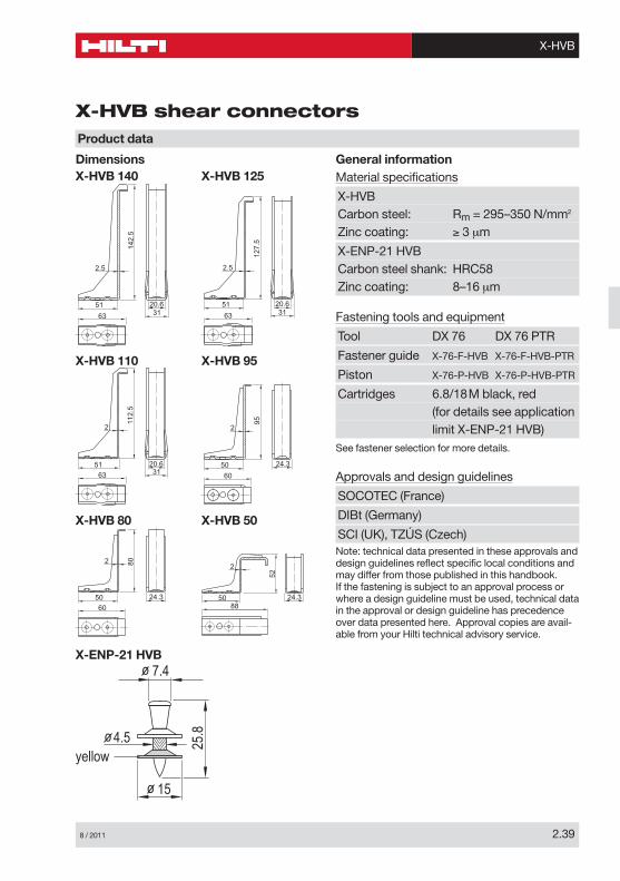
X-HVB shear connectors
General informationMaterial specifications
X-HVBCarbon steel: Rm = 295–350 N/mm2
Zinc coating: ≥ 3 µm
X-ENP-21 HVBCarbon steel shank: HRC58Zinc coating: 8–16 µm
Fastening tools and equipment
Tool DX 76 DX 76 PTR
Fastener guide X-76-F-HVB X-76-F-HVB-PTR
Piston X-76-P-HVB X-76-P-HVB-PTR
Cartridges 6.8/18M black, red(for details see applicationlimit X-ENP-21 HVB)
See fastener selection for more details.
Approvals and design guidelines
SOCOTEC (France)
DIBt (Germany)
SCI (UK), TZÚS (Czech)Note: technical data presented in these approvals anddesign guidelines reflect specific local conditions andmay differ from those published in this handbook.If the fastening is subject to an approval process orwhere a design guideline must be used, technical datain the approval or design guideline has precedenceover data presented here. Approval copies are avail-able from your Hilti technical advisory service.
Dimensions
2.5
63 3120.651
142.
5
20.651
127.
5
2.5
3163
Product data
X-HVB 140 X-HVB 125
20.651
2
112.
5
3163
24.350
95
2
60
X-HVB 110 X-HVB 95
24.350
802
60
24.350
52
2
88
X-HVB 80
yellow
o 4.5
o 7.4
25.8
o 15
X-ENP-21 HVB
X-HVB 50
X-HVB
2.40 8 / 2011
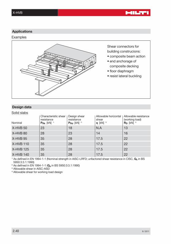
Solid slabsCharacteristic shear Design shear Allowable horizontal Allowable resistanceresistance resistance shear (working load)
Nominal PRk [kN] 1) PRd [kN] 2) q [kN] 3) RD [kN] 4)
X-HVB 50 23 18 N.A 13
X-HVB 80 28 23 14 16
X-HVB 95 35 28 17.5 22
X-HVB 110 35 28 17.5 22
X-HVB 125 35 28 17.5 22
X-HVB 140 35 28 17.5 221) As defined in EN 1994-1-1 (Nominal strength in AISC-LRFD; unfactored shear resistance in CISC, Qk in BS
5950:3:3.1:1990)2) As defined in EN 1994-1-1 (Qp in BS 5950:3:3.1:1990)3) Allowable shear in AISC-ASD4) Allowable shear for working load design
Design data
Examples
Applications
Shear connectors forbuilding construcions:• composite beam action• end anchorage of
composite decking• floor diaphragm• resist lateral buckling
8 / 2011 2.41
X-HVB
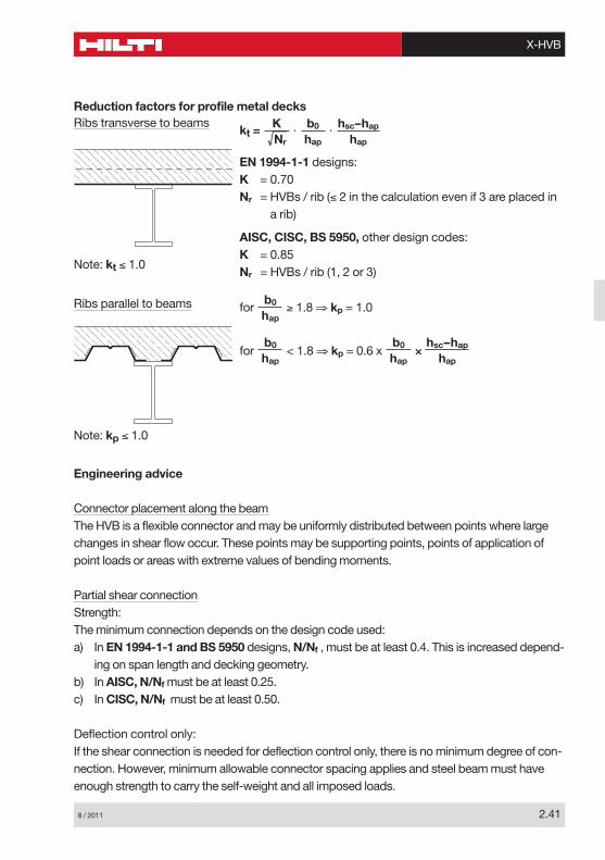
Reduction factors for profile metal decks
Engineering advice
Connector placement along the beamThe HVB is a flexible connector and may be uniformly distributed between points where largechanges in shear flow occur. These points may be supporting points, points of application ofpoint loads or areas with extreme values of bending moments.
Partial shear connectionStrength:The minimum connection depends on the design code used:a) In EN 1994-1-1 and BS 5950 designs, N/Nf , must be at least 0.4. This is increased depend-
ing on span length and decking geometry.b) In AISC, N/Nf must be at least 0.25.c) In CISC, N/Nf must be at least 0.50.
Deflection control only:If the shear connection is needed for deflection control only, there is no minimum degree of con-nection. However, minimum allowable connector spacing applies and steel beam must haveenough strength to carry the self-weight and all imposed loads.
Ribs transverse to beamskt = · ·
EN 1994-1-1 designs:K = 0.70Nr = HVBs / rib (≤ 2 in the calculation even if 3 are placed in
a rib)
AISC, CISC, BS 5950, other design codes:K = 0.85Nr = HVBs / rib (1, 2 or 3)
hsc–hap
hap
b0
hap
K����Nr
Note: kt ≤ 1.0
Ribs parallel to beams for ≥ 1.8 ⇒ kp = 1.0
for < 1.8 ⇒ kp = 0.6 x ××b0
hap
b0
hap
hsc–hap
hap
b0
hap
Note: kp ≤ 1.0
X-HVB
2.42 8 / 2011
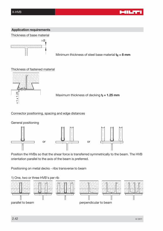
Thickness of base material
Application requirements
8
Minimum thickness of steel base material tII = 8 mm
Thickness of fastened material
1 x
1.25 Maximum thickness of decking tI = 1.25 mm
Connector positioning, spacing and edge distances
General positioning
Position the HVBs so that the shear force is transferred symmetrically to the beam. The HVBorientation parallel to the axis of the beam is preferred.
Positioning on metal decks - ribs transverse to beam
1) One, two or three HVB's per rib
or or
parallel to beam perpendicular to beam
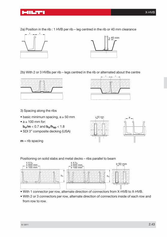
8 / 2011 2.43
X-HVB
= =
≥ 40 mm
2a) Position in the rib : 1 HVB per rib – leg centred in the rib or 40 mm clearance
= =
2b) With 2 or 3 HVBs per rib – legs centred in the rib or alternated about the centre
• basic minimum spacing, a ≥ 50 mm• a ≥ 100 mm for:bo/m < 0.7 and bo/hap < 1.8
• SDI 3” composite decking (USA)
m = rib spacing
≥ 50 mm a
3) Spacing along the ribs
• With 1 connector per row, alternate direction of connectors from X-HVB to X-HVB.• With 2 or 3 connectors per row, alternate direction of connectors inside of each row and
from row to row.
hc
≤ 600 mm≤ 4 hc
≥ 100 mm≤ 600 mm≤ 4 hc
≥ 100 mm
hc
≥ 50 mm
Positioning on solid slabs and metal decks – ribs parallel to beam
X-HVB
2.44 8 / 2011
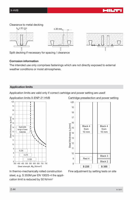
Corrosion informationThe intended use only comprises fastenings which are not directly exposed to externalweather conditions or moist atmospheres.
6350 400 450 500 550 600 650 700 750
7
8
9
10
11
12
13
14
15
16
17
18
10
>20
Ste
el th
ickn
ess,
tII
[mm
]
Steel strength, Rm [N/mm2]
Applicablerange of base
materials
S 235
S 275
S 355
8
9
10
11
12
13
14
15
16
17
18
10
>20
Ste
el th
ickn
ess
t II [m
m]
Black 4from
10 mm
Red 4Black 3
Black 2
Black 4from
10 mm
S 235 S 355
Application limits X-ENP-21 HVB Cartridge preselection and power setting
In thermo-mechanically rolled constructionsteel, e.g. S 355M per EN 10025-4 the appli-cation limit is reduced by 50 N/mm2
Fine adjustment by setting tests on site
Application limits
Application limits are valid only if correct cartridge and power setting are used!
Split decking if necessary for spacing / clearance
bo ≥ 60 mm
Clearance to metal decking
8 / 2011 2.45
X-HVB
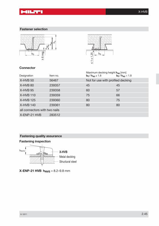
ConnectorMaximum decking height hap [mm]
Designation Item no. b0 / hap ≥ 1.8 b0 / hap < 1.8
X-HVB 50 56467 Not for use with profiled decking
X-HVB 80 239357 45 45
X-HVB 95 239358 60 57
X-HVB 110 239359 75 66
X-HVB 125 239360 80 75
X-HVB 140 239361 80 80
all connectors with two nails
X-ENP-21 HVB 283512
hNVS X-HVB
Metal decking
Structural steel
X-ENP-21 HVB hNVS = 8.2–9.8 mm
Fastening inspection
Fastening quality assurance
h c
h sc
h ap
b0
≥ 8
mm b0
≤ 1
x 1,
25
Fastener selection
X-HVB
Hilti (Gt. Britain) Limited,
1 Trafford Wharf Road, Trafford Park, Manchester M17 1BY
Telephone:
0800 886 100
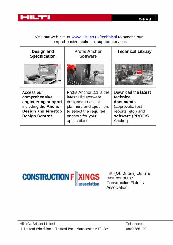
Visit our web site at www.Hilti.co.uk/technical to access our comprehensive technical support services
Design and Specification
Profis Anchor Software
Technical Library
Access our comprehensive engineering support, including the Anchor Design and Firestop Design Centres
Profis Anchor 2.1 is the latest Hilti software, designed to assist planners and specifiers to select the required anchors for your applications.
Download the latest technical documents (approvals, test reports, etc.) and software (PROFIS Anchor).
Hilti (Gt. Britain) Ltd is a member of the Construction Fixings Association.