High Temperature Superconductor (HTS) Solenoid of the Presentation • Overview of the solenoid work...
20
Superconducting Magnet Division Ramesh Gupta, Superconducting Magnet Division (SMD), BNL HTS Solenoid SRF Gun Design Review@BNL, 12/14/05 1 http://www.bnl.gov/magnets/staff/gupta High Temperature Superconductor (HTS) Solenoid Ramesh Gupta Superconducting Magnet Division (SMD) Brookhaven National Laboratory Upton, NY 11973 USA
-
Upload
vuongtuong -
Category
Documents
-
view
236 -
download
1
Transcript of High Temperature Superconductor (HTS) Solenoid of the Presentation • Overview of the solenoid work...
Superconducting Magnet Division
Ramesh Gupta, Superconducting Magnet Division (SMD), BNL HTS Solenoid SRF Gun Design Review@BNL, 12/14/05 1
http://www.bnl.gov/magnets/staff/gupta
High Temperature Superconductor (HTS) Solenoid
Ramesh GuptaSuperconducting Magnet Division (SMD)
Brookhaven National LaboratoryUpton, NY 11973 USA

Superconducting Magnet Division
Ramesh Gupta, Superconducting Magnet Division (SMD), BNL HTS Solenoid SRF Gun Design Review@BNL, 12/14/05 2
Overview of the Presentation
• Overview of the solenoid work at Superconducting Magnet Division
• HTS (High Temperature Superconductor) solenoid overall design
• Detailed magnetic design
An optimized design after several iterations (overall envelop and magnet parameters are not expected to change now, even if some changes are required in internal parameters)
• Results of the measurements of HTS wires received for the project
• Status
• Future Plans
Next presentation - HTS Lead Design & Overall Engineering Concepts by Steve Plate - continues on the same subject. Steve Plate is project engineer of HTS Solenoid.

Superconducting Magnet Division
Ramesh Gupta, Superconducting Magnet Division (SMD), BNL HTS Solenoid SRF Gun Design Review@BNL, 12/14/05 3
HTS Solenoid Work At SMD
Superconducting Magnet Division (SMD) is responsible for•Magnetic and engineering design of the solenoid
•Provide field map and optimize solution with CAD
•Test HTS wires and individual coils
•Build solenoid
•Test solenoid to certify performance and measure fringe fields
•Develop design and procedures to keep fringe field within acceptable limits
•Design and Build HTS leads and related hardware
•Work with AES to develop a good interface scenario

Superconducting Magnet Division
Ramesh Gupta, Superconducting Magnet Division (SMD), BNL HTS Solenoid SRF Gun Design Review@BNL, 12/14/05 4
Main Features of the Design
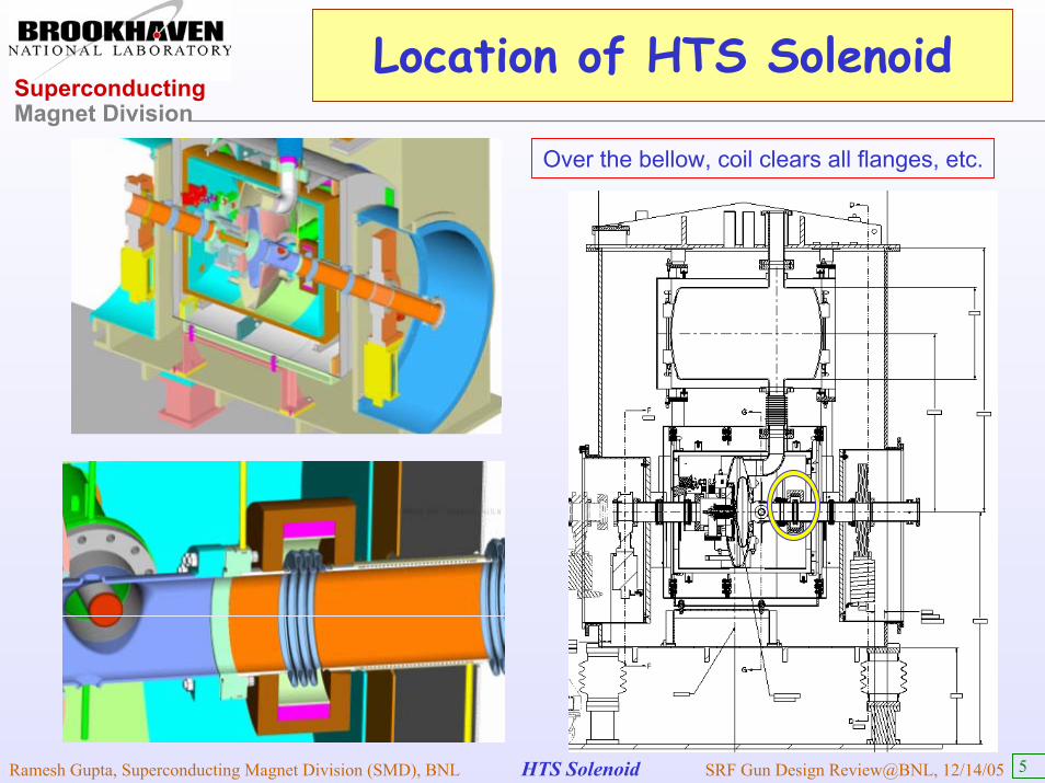
Main Features of the Current HTS Solenoid Design• Requires practically no extra space, as it goes entirely over the bellow
• Coil inner radius is increased so that it can be slid over all flanges, etc.
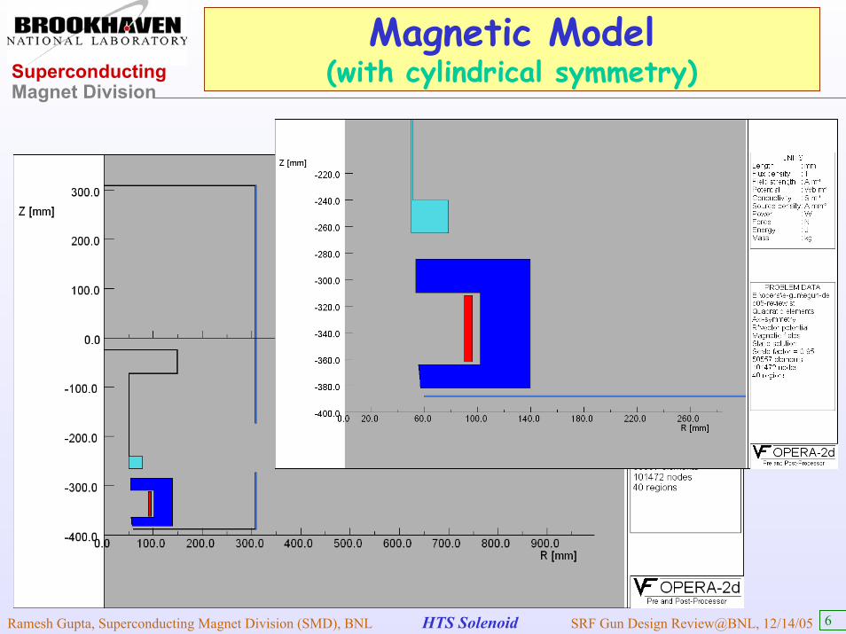
• Yoke inner radius (much smaller than coil inner radius) defines the field
• Maximum field in the yoke is kept low (0.3 T or 3 kG); if residual field is still a concern, then demagnetization cycle will be specified for normal operation
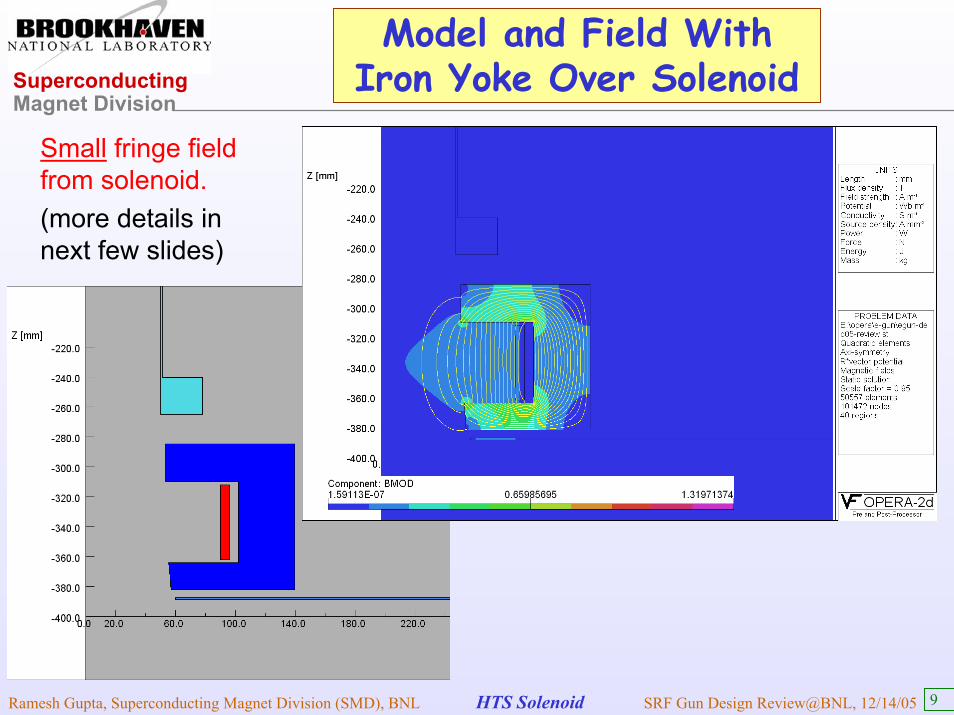
• Yoke over coil significantly reduces the fringe field on mu-metal shield
• Solenoid generates desired field at 77 K. LN2 temperature facilitates simple and inexpensive testing, lower temperature gives additional operating margin
• A low current (maximum 50 Ampere), allows simpler current leads and a low cost power supply
Superconducting Magnet Division
Ramesh Gupta, Superconducting Magnet Division (SMD), BNL HTS Solenoid SRF Gun Design Review@BNL, 12/14/05 5
Location of HTS Solenoid
Over the bellow, coil clears all flanges, etc.
Superconducting Magnet Division
Ramesh Gupta, Superconducting Magnet Division (SMD), BNL HTS Solenoid SRF Gun Design Review@BNL, 12/14/05 6
Magnetic Model (with cylindrical symmetry)

Superconducting Magnet Division
Ramesh Gupta, Superconducting Magnet Division (SMD), BNL HTS Solenoid SRF Gun Design Review@BNL, 12/14/05 7
Desired Focussing from Solenoid
≈∫ dzBz2 1 T2 . mm
Contour of B z2
Variation of
along the z- axis
B z2
Basic Requirements :
Basic integral requirements are met at ~9750 Amp-turns

Superconducting Magnet Division
Ramesh Gupta, Superconducting Magnet Division (SMD), BNL HTS Solenoid SRF Gun Design Review@BNL, 12/14/05 8
Fringe Field
1. Should be less than 1.5 kG (0.15 T) on the superconductor when the solenoid is ON.
2. Should be less than a few mG on the cavity when the cavity is turning to superconducting state (solenoid is OFF at this time).
3. Field calculations (for beam focussing, etc.) must include the influence of shielding from superconductor and mu-metal
• Action item from last review: Check Hc1 of NbTi Flange
Superconducting Magnet Division
Ramesh Gupta, Superconducting Magnet Division (SMD), BNL HTS Solenoid SRF Gun Design Review@BNL, 12/14/05 9
Model and Field With Iron Yoke Over Solenoid
Small fringe field from solenoid.(more details in next few slides)

Superconducting Magnet Division
Ramesh Gupta, Superconducting Magnet Division (SMD), BNL HTS Solenoid SRF Gun Design Review@BNL, 12/14/05 10
Field in the Yoke Iron (Small)
The maximum field is iron yoke is ~0.6 T (well below saturation magnetization). Yoke width is made wider on cavity side to reduce the maximum to ~0.3 T. This should help reduce the impact of residual magnetization.
It may be useful to put some extra shielding iron (may be mu-metal shield) at appropriate place (a) above solenoid towards right side of NbTi flange (b) below mu-metal shield ( or increase thickness of mu-metal there)

Superconducting Magnet Division
Ramesh Gupta, Superconducting Magnet Division (SMD), BNL HTS Solenoid SRF Gun Design Review@BNL, 12/14/05 11
Field Components as Experienced by the Beam & Possibility of Tracking by OPERA
Axial Component
Radial Component
EM software OPERA facilitates tracking allowing a direct use of field
components as experiencedby the beam.
This was partly usedin the design of AGS snake.
Can be done here too !
Beam Trajectory

Superconducting Magnet Division
Ramesh Gupta, Superconducting Magnet Division (SMD), BNL HTS Solenoid SRF Gun Design Review@BNL, 12/14/05 12
Magnetic Shielding by Mu-metal and Superconductor
Field in mu-metal at design currentMax. field ~0.16 T. if it’s too much, increase the thickness of shield in region near yoke)
Field in sc cavity structure at design current(maximum ~0.3 mT, can be further reduced by
extra iron or mu-metal shield)

Superconducting Magnet Division
Ramesh Gupta, Superconducting Magnet Division (SMD), BNL HTS Solenoid SRF Gun Design Review@BNL, 12/14/05 13
Superconducting Shielding
Note: Model above may be a better representation rather than one on right.But the fact that NbTi flange cannot provide a Meissner shield, does not limit Nb tube providing a shielding (as it is well below its Hc1). Also note that there is practically no difference in the field map where the beam is. Also it makes a little difference if we go through an iron demagnetization cycle.
Superconductors: Nb(Tube) & NbTi(Flange)Niobium (Nb) is only one of three metals that is Type II superconductor (others are vanadium and technetium). Its Hc1 is ~ kG.NbTi is a Type II superconductor and it has a low value of Hc1 (Hc1 ~ G) <= action item.NbTi can't provide Meissner shield @100 G (but will resist any change due to high Hc2).

Superconducting Magnet Division
Ramesh Gupta, Superconducting Magnet Division (SMD), BNL HTS Solenoid SRF Gun Design Review@BNL, 12/14/05 14
Magnitude of Field (at design current) in Cavity (and beyond)
Note: The maximum field in the cavity at the design current is ~ mT. At zero current, we shall have much smaller field (the source is residual magnetization of iron yoke or mu-metal). Residual field should be low since the iron yoke over solenoid is not highly magnetized. Additional component of the software will be purchased for such calculations. Moreover, iron demagnetization cycles are planned. As a part of our test program, we would run demagnetization cycles, to determine if they are necessary during the operation.
Superconducting Magnet Division
Ramesh Gupta, Superconducting Magnet Division (SMD), BNL HTS Solenoid SRF Gun Design Review@BNL, 12/14/05 15
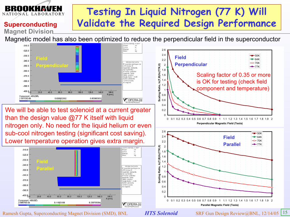
Testing In Liquid Nitrogen (77 K) Will Validate the Required Design Performance
0
0.2
0.4
0.6
0.8
1
1.2
1.4
1.6
1.8
2
2.2
2.4
2.6
0 0.1 0.2 0.3 0.4 0.5 0.6 0.7 0.8 0.9 1 1.1 1.2 1.3 1.4 1.5 1.6 1.7 1.8 1.9 2
Perpendicular Magnetic Field (Tesla)
Scal
ing
Rat
io, I
c(T,
B)/I
c(77
K,0
)
50K64K70K77K
0
0.2
0.4
0.6
0.8
1
1.2
1.4
1.6
1.8
2
2.2
2.4
2.6
0 0.1 0.2 0.3 0.4 0.5 0.6 0.7 0.8 0.9 1 1.1 1.2 1.3 1.4 1.5 1.6 1.7 1.8 1.9 2
Parallel Magnetic Field (Tesla)
Scal
ing
Rat
io, I
c(T,
B)/I
c(77
K,0
)
50K64K70K77K
Magnetic model has also been optimized to reduce the perpendicular field in the superconductor
Scaling factor of 0.35 or more is OK for testing (check field component and temperature)
FieldPerpendicular
FieldParallel
FieldPerpendicular
FieldParallel
We will be able to test solenoid at a current greater than the design value @77 K itself with liquid nitrogen only. No need for the liquid helium or even sub-cool nitrogen testing (significant cost saving).Lower temperature operation gives extra margin.

Superconducting Magnet Division
Ramesh Gupta, Superconducting Magnet Division (SMD), BNL HTS Solenoid SRF Gun Design Review@BNL, 12/14/05 16
Measurements of Two HTS Wire Samplesat Superconducting Magnet Division (SMD)
0.0
0.2
0.4
0.6
0.8
1.0
1.2
1.4
1.6
1.8
2.0
0 10 20 30 40 50 60 70 80 90 100 110 120 130 140 150 160 170
Current (Amp)
Volta
ge G
radi
ent (µV
/cm
)
UninsulatedInsulated
Two reels of HTS wires were obtained from American Superconductor (through AES) with a spec (1 µV/cm) of 145 A at 77 K, self field.We (SMD@BNL) recently completed the tests of samples taken from these wires. Measurements show that the wires exceeds the specification.
152 A& 157 A
Superconducting Magnet Division
Ramesh Gupta, Superconducting Magnet Division (SMD), BNL HTS Solenoid SRF Gun Design Review@BNL, 12/14/05 17
Status
Tasks completed
• Overall magnet design and detailed magnetic design• Procurement and test of the required HTS wire (Tape)HTS leads and feed developed (see next presentation by Steve Plate)
Work to continue: iterations, if required, and detailed engineering design.
Tasks well underway (likely to be presented in the next monthly review)
• Initial engineering design of the solenoid• Overall concept of assembly and integration with rest of the system developed
Need feed back from AP group on various mechanical tolerances in construction and in positioning errors (radial, axial, angular)

Superconducting Magnet Division
Ramesh Gupta, Superconducting Magnet Division (SMD), BNL HTS Solenoid SRF Gun Design Review@BNL, 12/14/05 18
Future Plans
Tasks planned (to be started soon after receiving OK for construction)• Purchase material for yoke and other components.
• Purchase software for calculating the influence of magnetized iron yoke.
• Practice winding with stainless steel tape to experimentally determine a better choice of coil winding pattern (pancake or layer winding).
• Do detailed engineering of solenoid, HTS leads, feed-through, etc.• Wind HTS coil(s) (test each coil individually at 77 K for pancake coil option) • Assemble all coils and test coil package at liquid nitrogen (LN2).• Put yoke around the coil (it may be put temporary for testing purpose only).• Test HTS solenoid in liquid nitrogen to prove that it meets the design performance• Do fringe field measurements and iron demagnetization cycles. • Build HTS leads, feed-through, etc.• Deliver solenoid coil package and yoke to Jefferson Lab (BNL will do some more work later on after getting it back from Jefferson Lab).
Details plans yet to be developed for assembly and integration of the solenoid with the rest of the system, including who will do what and when?

Superconducting Magnet Division
Ramesh Gupta, Superconducting Magnet Division (SMD), BNL HTS Solenoid SRF Gun Design Review@BNL, 12/14/05 19
HTS Coils Wound at SMD for Various Projects
Solenoid coil wound with earlier winding machine.
HTS racetrack coil wound with the new computer controlled winding machine.
SS Tape
HTS Tape
We are on standby to wind solenoid coils !

Superconducting Magnet Division
Ramesh Gupta, Superconducting Magnet Division (SMD), BNL HTS Solenoid SRF Gun Design Review@BNL, 12/14/05 20
SUMMARY
• The basic HTS solenoid design is in place. The design seems to satisfy all requirements.
• Residual fields are low and will be further reduced with a demagnetization cycle. This (apart from testing solenoid for validating design field performance) will be a part of overall verification process.
• All tests to the design field will be carried out at liquid Nitrogen (77 K). This simplifies the magnet testing and significantly reduces cost.
• Most design work is nearly complete. We are ready to move aheadwith the construction (will start as soon as the funding is received).
• The start of construction is delayed because of the delay in funding. The estimated time of building and testing solenoid was one year.
• Since design is continuing with support from CAD, the full impact of delay is reduced. But the scheduled delivery date of 08/06 is unlikely to be met. To avoid significant delay, funding should be available soon.