10 T HTS Solenoid - Brookhaven National Laboratory Magnet Division Ramesh Gupta, PBL SBIR Meeting...
33
Superconducting Magnet Division Ramesh Gupta, PBL SBIR Meeting @BNL, October 2-3, 2008 0 10 T HTS Solenoid Ramesh Gupta BNL
Transcript of 10 T HTS Solenoid - Brookhaven National Laboratory Magnet Division Ramesh Gupta, PBL SBIR Meeting...
Superconducting Magnet Division
Ramesh Gupta, PBL SBIR Meeting @BNL, October 2-3, 2008 0
10 T HTS Solenoid
Ramesh GuptaBNL
Superconducting Magnet Division
Ramesh Gupta, PBL SBIR Meeting @BNL, October 2-3, 2008 1
Persons Involved at SMD/BNL
• Mike Anerella• Arup Ghosh• Ramesh Gupta• Steve Plate• Bill Sampson• Peter Wanderer• … and valuable designers and technicians
Superconducting Magnet Division
Ramesh Gupta, PBL SBIR Meeting @BNL, October 2-3, 2008 2
Overview
• Goal of the program
• Proposed Enhancements
• Preliminary solenoid design
• Future plans and initial schedule

Superconducting Magnet Division
Ramesh Gupta, PBL SBIR Meeting @BNL, October 2-3, 2008 3
GOALS OF THIS SBIR (related to the component on HTS solenoid)
• Ultimate stated goal (target) of the solenoid proposal– 10 T, 10 cm solenoid operating at 30-40 K (if we were not limited by budget)
• Well defined deliverable (along with other components of SBIR)– 10 T at 4 K (and ~5 T at 33 K) in a solenoid with coil i.d. approaching 10 cm– Measure performance (achievable B) as a function of temperature (4 -70 K)
• Other vaguely defined goals (mentioned at various places)– Develop technology for 10 T, 10 cm solenoid operating at 30-40 K– Carry out this R&D as a step towards small bore, high field solenoids at 4 K– Develop HTS technology for other muon collider magnets that reside in high
radiation environment and/or may benefit from high temperature operation
Benefit from this SBIR to launch more in related fields

Superconducting Magnet Division
Ramesh Gupta, PBL SBIR Meeting @BNL, October 2-3, 2008 4
10 T HTS Solenoid Designs (as presented in the proposal)
CourtesyB. Weggel
• In the original SBIR proposal, we promised case (2) - which was for coil i.d. = 66.5 mmo Case (1) was for coil i.d. = 87.2 mm o Case (3) 9.8 T SuperPower/NHFML solenoid was for coil i.d. = 19 mm
All cases for 10 T at 4.2 K

Superconducting Magnet Division
Ramesh Gupta, PBL SBIR Meeting @BNL, October 2-3, 2008 5
HTS Solenoid Enhancement #1 –
Larger Bore
• In the original proposal, we promised 66.5 mm coil i.d.• Thanks to better Je, we are now aiming for a significantly higher value – 110 mm coil i.d.
this is better than even case (1) of the original proposal, which was for 87.2 mm coil i.d. (more on this later)
All cases for 10 T at 4.2 K
Large coil i.d. is important for some muon collider solenoids

Superconducting Magnet Division
Ramesh Gupta, PBL SBIR Meeting @BNL, October 2-3, 2008 6
HTS Solenoid Enhancement #2-
Higher Field or Higher Temperature
• In the original proposal, we promised 10 T in 66.5 mm coil i.d. at 4 K• Thanks to the collaboration & promised contributions from SuperPower, we are now aiming for 20+ T in ~29 mm coil i.d. (more on this later)• Alternatively, we can say that we are now aiming a demonstration of ~10 T at higher temperature (30 K) in ~29 mm coil i.d. (more on this later)
High field HTS magnets, particularly high field solenoids, are important for many applications (particularly in muon collider)
In this SBIR proposal, we had mentioned 10 T at 30-40 K

Superconducting Magnet Division
Ramesh Gupta, PBL SBIR Meeting @BNL, October 2-3, 2008 7
HTS Solenoid Enhancement #3 –
Making an important test facility
We will make a split-pair 10 T solenoid with sufficient bore (10 cm) and gap in between the two coils to facilitate measurements of HTS as a function of both magnitude and direction of field, at various temperature --- higher than 4K temperature measurements are important for this field.
• Current carrying capacity of HTS depends critically on the direction of field, in addition to the magnitude of the field and on the temperature. There is no good facility for such measurements.• Thanks to the interest of BNL, this solenoid can help create such a facility.
Without gap, the expected field is ~12 T (assuming 30% improvement in conductor).Thus we have 20% margin (more on this later).

Superconducting Magnet Division
Ramesh Gupta, PBL SBIR Meeting @BNL, October 2-3, 2008 8
Review of the field and update on discussions with
our new collaborators

Superconducting Magnet Division
Ramesh Gupta, PBL SBIR Meeting @BNL, October 2-3, 2008 9
SuperPower HTS Solenoid inside the NHMFL 19 T Solenoid (providing background field)
SuperPower made a ~10 T small aperture HTS solenoid with its own conductor and tested it in NHMFL’s unique, 19-tesla, 20-centimeter wide-bore, 20-megawatt Bitter magnet (solenoid)
2G HF insert coil showing terminals, overbanding and partial support structure. Flange OD is 127 mm.

Superconducting Magnet Division
Ramesh Gupta, PBL SBIR Meeting @BNL, October 2-3, 2008 10
SuperPower/NHFML YBCO Solenoid
Low Temperature Superconductivity Workshop, 10/29/07 – 19 –
High field insert coil achieves world records for highest HTS field, highest magnetic field by a SC magnet
0.0
5.0
10.0
15.0
20.0
25.0
30.0
0 50 100 150 200 250
Current (A)
Cent
ral F
ield
(T)
19T background self field
3.2 T4.2K Peak Radial Field @ Ic, self field
2.7 T4.2 K Peak Radial Field @ Ic, 19 T bkgd (axial)
274.6 A/mm24.2 K Je @ Ic, 19 T background (axial)
9.81 T9.81 T4.2 K Central field –self field
26.8 T26.8 T4.2K Central Field – 19 T background (axial)
485,1004.2 K Amp Turns @ Ic –19 T background (axial)
175 A 4.2 K Coil Ic – 19 T background (axial)
346.7 A/mm24.2 K Je @ Ic, self field
612,6124.2 K Amp Turns @ Ic-self field
221 A4.2 K Coil Ic - self field
72 A – 82 A (77K, sf)
Ic of Wires in Coil
26.8 T @ 175 A
9.81 T @ 221 A
Peak hoop stress ~ 215 MPa, well below tape limit

Superconducting Magnet Division
Ramesh Gupta, PBL SBIR Meeting @BNL, October 2-3, 2008 11
Superconducting Magnet Division
Ramesh Gupta, BNL 2G HTS Magnet R&D SuperPower, September 9, 2008 0
2G HTS Magnet R&D
Ramesh Gupta
http://www.bnl.gov/magnets/staff/gupta
A discussion on the potential of 2G conductors in more HTS magnet applications in accelerators and medical sciences
A very productive visit to SuperPower on 9/9/2008
BNL/PBL/SuperPower Collaboration (1)

Superconducting Magnet Division
Ramesh Gupta, PBL SBIR Meeting @BNL, October 2-3, 2008 12
BNL/PBL/SuperPower Collaboration (2)
Low Temperature Superconductivity Workshop, 10/29/07 – 4 –
SuperPower’s 2G pilot manufacturing facilities have been operational since 2006
Pilot IBAD
Majority of investment already made for 1000 km/year capability
Pilot HTS
Pilot Substrate Electropolishing Pilot Buffer
SuperPower Site in Schenectady, NY

Superconducting Magnet Division
Ramesh Gupta, PBL SBIR Meeting @BNL, October 2-3, 2008 13
INFORMAL SEMINAR
SuperPower Second Generation (2G)
HTS Wire for Magnet Applications
BY
Drew Hazelton Trudy Lehner
Tuesday, September 23, 2008
2:30 p.m.
902A Conference Room 63
And a return visit of SuperPower to BNL on 9/23/2008
BNL/PBL/SuperPower Collaboration (3)
• First meeting at ASC2008 where we discussed the possibility for SuperPower providing insert coil for high field solenoid.
• The collaboration was finalized during a visit to SuperPower.
• Now SuperPower has promised two coils. We are working together so that the length of our coils in split-pair solenoid matches with the length of their coils.

Superconducting Magnet Division
Ramesh Gupta, PBL SBIR Meeting @BNL, October 2-3, 2008 14
Angular Dependence of Ic
in HTS
0 5 10 15 20 25 30 350
5
10
15
20
25
30
35
40
45
4.2K//c 4.2K//ab
J c (M
A/c
m2 )
μ0H (Tesla)
Data by Z. Chen at NHMFL / FSU (2007)
SuperPower (earlier sample)
Data (solid figures) taken on bridge sample. Dashed red line is hypothetical curve.
Field perpendicular - direction of lower Ic(no doping)Unlike in LTS, Ic generally has a strong
angular dependence in presence of field

Superconducting Magnet Division
Ramesh Gupta, PBL SBIR Meeting @BNL, October 2-3, 2008 15
Large Improvements in Ic
by Doping77
K, 1
T
• Doping has brought major improvements in in-field Ic and has a major influence on the angular dependence of Ic
It is very important that we examine in-field Ic as a function of field at various temperatures
• As a part of FRIB R&D we are purchasing three 100 meter pieces of 2G conductors with three different dopings from SuperPower. This is in addition to two 100 meter pieces of 2G conductor with nano-dots from ASC. • We will examine performance of coils made with these conductors at lower temperatures. • This should help HTS solenoid in 2nd year.

Superconducting Magnet Division
Ramesh Gupta, PBL SBIR Meeting @BNL, October 2-3, 2008 16
New Coils at SuperPower

Superconducting Magnet Division
Ramesh Gupta, PBL SBIR Meeting @BNL, October 2-3, 2008 17
Solenoid with Improved Conductor
Will this improvement be retained at lower temperature ???
We are taking credit of this 30% improvement in our design work.
Superconducting Magnet Division
Ramesh Gupta, PBL SBIR Meeting @BNL, October 2-3, 2008 18
HTS Solenoid Design

Superconducting Magnet Division
Ramesh Gupta, PBL SBIR Meeting @BNL, October 2-3, 2008 19
• Coil i.d. : 110 mm
• Coil o.d. : 180 mm (175 mm or more)
• Clear bore : 100 mm
• Coil length (2 coils) : 55 mm
• Gap between two coils : 18 mm (15 mm or more)
• Total length of split pair solenoid : 128 mm (2*55 + 18)
• Je (@10 T, 4K) : 450 A/mm2 (30% over 2007 SuperPower solenoid)
• Design current (@10 T, 4K) : 287 A (30% over 2007 SuperPower solenoid)
• No. of coils : 24 (12 double pan cake made with ~4.1 mm wide tape)
• Field at the center : 10.7 T (12 T without gap - margin over no-gap baseline)
HTS Solenoid (preliminary parameters)

Superconducting Magnet Division
Ramesh Gupta, PBL SBIR Meeting @BNL, October 2-3, 2008 20
Field on the Conductor of the Solenoid
• Coil i.d. : 110 mm• Coil o.d. : 180 mm • Coil length (each) : 55 mm • Gap between two coils : 18 mm • Total length : 128 mm • Je (@10 T, 4K) : 450 A/mm2
• No. of coils : 24 • Field at the center : 10.7 T
Peak field on the conductor is ~12.4 T
• Direction of the field is important. • In fact we are limited by the field perpendicular value and not the field maximum value.• Optimization of this is a part of the detailed design- yet to be carried out.

Superconducting Magnet Division
Ramesh Gupta, PBL SBIR Meeting @BNL, October 2-3, 2008 21
Field inside the solenoid (near the middle)
Between two coils
On the solenoid axisWe have some margin:
~10.7 T with gap, rather than ~12 T without gap (and 13.2 T, if conductor price to drop and we were able to put 4 extra coils in that gap - 24+4 = 28 coils, ~ 3 km total length of conductor)
• Coil i.d. : 110 mm• Coil o.d. : 180 mm • Coil length (each) : 55 mm • Gap between two coils : 18 mm • Total length : 128 mm • Je (@10 T, 4K) : 450 A/mm2
• No. of coils : 24 • Field at the center : 10.7 T

Superconducting Magnet Division
Ramesh Gupta, PBL SBIR Meeting @BNL, October 2-3, 2008 22
Baseline Design of the Solenoid (no gap between the coils)
• Je in coil : ~450 A/mm2
(30% improvement assumed)NO Gap between coils
• solenoid coil i.d. : 110 mm• clear bore i.d. : 100 mm
Bo ~ 12 TBpk ~ 14 T
Baseline design should have a reasonable margin to assure success (10 T @ 4K)

Superconducting Magnet Division
Ramesh Gupta, PBL SBIR Meeting @BNL, October 2-3, 2008 23
HTS Solenoid with SupePower
Insert
• Je in our solenoid : ~450 A/mm2
• Je in SuperPower solenoid: ~350 A/mm2
Gap between the two coils : 18 mm• i.d. of our solenoid : 110 mm
• i.d. of SuperPower Solenoid : 28.6 mm
Bo ~18 T

Superconducting Magnet Division
Ramesh Gupta, PBL SBIR Meeting @BNL, October 2-3, 2008 24
HTS Solenoid with SupePower
Insert (no gap between coils)
• Je in our solenoid : ~450 A/mm2
• Je in SuperPower solenoid: ~350 A/mm2
Gap between the two coils : 0 mm• i.d. of our solenoid : 110 mm
• i.d. of SuperPower Solenoid : 28.6 mm
Bo ~ 23 T

Superconducting Magnet Division
Ramesh Gupta, PBL SBIR Meeting @BNL, October 2-3, 2008 25
Strength of YBCO
• Question: can YBCO take these large stress associated with high fields ?•Yes it can! But we will have stainless steel wrap also !!!
Superconducting Magnet Division
Ramesh Gupta, PBL SBIR Meeting @BNL, October 2-3, 2008 26
Fabrication and Schedule

Superconducting Magnet Division
Ramesh Gupta, PBL SBIR Meeting @BNL, October 2-3, 2008 27
Winding of Coils
Courtesy/Contributions: Dilgen, Ince
FRIB/RIA Coils being wound with S.S. tape over HTS
• We will continue to wind coils with stainless steel tape.
• Stainless steel tape gives extra strength. As such it is not needed in this solenoid. But we will continue to use it, in support of future high field solenoid work.

Superconducting Magnet Division
Ramesh Gupta, PBL SBIR Meeting @BNL, October 2-3, 2008 28
Preliminary Support• We will use stainless steel overbend (wrap), flanges in the ends and a disc with a hole for sample holder.• Bob Weggle is doing stress calculations.• Detailed engineering design will be carried out in next few months.
Sample will have its own on-board heaters to vary temperature.
Temperature of the solenoid may rise a bit (OK for HTS)
Superconducting Magnet Division
Ramesh Gupta, PBL SBIR Meeting @BNL, October 2-3, 2008 29
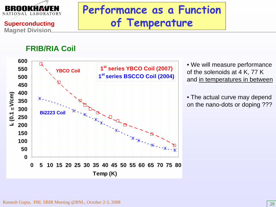
Performance as a Function of Temperature
1st series YBCO Coil (2007) 1st series BSCCO Coil (2004)
050
100150200250300350400450500550600
0 5 10 15 20 25 30 35 40 45 50 55 60 65 70 75 80Temp (K)
I c (0
.1 π
V/cm
)
YBCO Coil
Bi2223 Coil
• We will measure performance of the solenoids at 4 K, 77 K and in temperatures in between
• The actual curve may depend on the nano-dots or doping ???
FRIB/RIA Coil

Superconducting Magnet Division
Ramesh Gupta, PBL SBIR Meeting @BNL, October 2-3, 2008 30
Revised Preliminary Schedule
Year #10 – 2 months Conceptual design studies0– 12 months Conductor testing (R&D samples and actual conductor)1 – 6 months Engineering design3 – 6 months Coil tooling design and construction4 – 6 months First batch of conductor received 7– 8 months Coil winding and individual LN2 coil tests (first set)9 – 10 months Support structure fabrication and first assembly of solenoid (12 coils)11 – 12 months First half of HTS solenoid tested in a temperature range of 4K-77K
Year #212– 18 months Conductor testing continues 14– 16 months Second batch of conductor received 15 – 17 months Coil winding and individual LN2 coil tests (second set)18 – 19 months Re-assembly of solenoid with all 24 coils 20 – 21 months HTS solenoid testing in a range of temperature (4K-77K)22 – 23 months Report preparation
Enhancements - insert coils from Superpower and split-pair assembly - are outside the original scope of the SBIR and are not mentioned explicitly in the schedule.

Superconducting Magnet Division
Ramesh Gupta, PBL SBIR Meeting @BNL, October 2-3, 2008 31
Induction of HTS Solenoid at BNL Conductor Testing Facility
HTS Tapes Tested at BNL @5 T Field as a Function of Temperature
400
500
600
700
800
900
1000
1100
1200
1300
14 16 18 20 22 24 26 28 30 32 34 36 38 40T (K)
Ic (1
μV/c
m)
Sample#1
Sample#2
This magnet would produce a unique research facility for testing the performance of HTS as a function of magnitude of the field, direction of field and as a function of temperature.
These are critical measurements for HTS R&D. And right now there is no convenient facility.
• An earlier test as a function of temperature, where the temperature was changed with the help of heaters.
• At that time we could not change the direction of field, and hence could not measure the angular dependence.
• Also that magnet could not go to very high field either.

Superconducting Magnet Division
Ramesh Gupta, PBL SBIR Meeting @BNL, October 2-3, 2008 32
SUMMARY
• Thanks to the improvements in second generation HTS (YBCO), we are off to a very good start.
• We have significantly increased the coil i.d. over the proposal submitted – 66.5 mm to 110 mm (100 mm clear bore).
• Thanks to the expected collaborations with SuperPower, we should be able to obtain ~20 T at 4 K or 10 T at ~33 K, however, in a smaller bore.
• At the end of the project, we hope to turn this solenoid in to a useful conductor test facility to measure Ic both as a function of magnitude of the field and direction of the field, which is crucial for such R&D.
Perhaps very few SBIR can boast such enhancements.
•A successful outcome of this should help create more such proposals.