High Temperature Superconducting (HTS) technology for wind ... · High Temperature Superconducting...
69
General rights Copyright and moral rights for the publications made accessible in the public portal are retained by the authors and/or other copyright owners and it is a condition of accessing publications that users recognise and abide by the legal requirements associated with these rights. Users may download and print one copy of any publication from the public portal for the purpose of private study or research. You may not further distribute the material or use it for any profit-making activity or commercial gain You may freely distribute the URL identifying the publication in the public portal If you believe that this document breaches copyright please contact us providing details, and we will remove access to the work immediately and investigate your claim. Downloaded from orbit.dtu.dk on: May 23, 2020 High Temperature Superconducting (HTS) technology for wind generators Jensen, Bogi Bech; Abrahamsen, Asger Bech Publication date: 2011 Document Version Publisher's PDF, also known as Version of record Link back to DTU Orbit Citation (APA): Jensen, B. B. (Invited author), & Abrahamsen, A. B. (Invited author). (2011). High Temperature Superconducting (HTS) technology for wind generators. Sound/Visual production (digital) http://www.wind- drivetrain.com/presentations
Transcript of High Temperature Superconducting (HTS) technology for wind ... · High Temperature Superconducting...

General rights Copyright and moral rights for the publications made accessible in the public portal are retained by the authors and/or other copyright owners and it is a condition of accessing publications that users recognise and abide by the legal requirements associated with these rights.
Users may download and print one copy of any publication from the public portal for the purpose of private study or research.
You may not further distribute the material or use it for any profit-making activity or commercial gain
You may freely distribute the URL identifying the publication in the public portal If you believe that this document breaches copyright please contact us providing details, and we will remove access to the work immediately and investigate your claim.
Downloaded from orbit.dtu.dk on: May 23, 2020
High Temperature Superconducting (HTS) technology for wind generators
Jensen, Bogi Bech; Abrahamsen, Asger Bech
Publication date:2011
Document VersionPublisher's PDF, also known as Version of record
Link back to DTU Orbit
Citation (APA):Jensen, B. B. (Invited author), & Abrahamsen, A. B. (Invited author). (2011). High Temperature Superconducting(HTS) technology for wind generators. Sound/Visual production (digital) http://www.wind-drivetrain.com/presentations
High Temperature Superconducting (HTS) Technology for Generators
Dr Bogi Bech Jensen1, Associate Professor ([email protected])
Dr Asger B. Abrahamsen2, Senior Scientist
1Depertment of Electrical Engineering, Technical University of Denmark (DTU) 2Materials Research Division, Risø DTU
17th – 19th October 2011
2nd International Conference on Drivetrain Concepts for Wind Turbines, Bremen, Germany.

2 DTU Electrical Engineering, Technical University of Denmark
Overview
• Working principle and requirements for superconducting generators in wind turbines
• Considerations for wind turbine solutions for large scale offshore wind power development
• Benefits of the HTS technology in terms of efficiency and power density
• Assessing the current cost situation
• How can HTS technology become commercially viable

3 DTU Electrical Engineering, Technical University of Denmark
Level of experience with HTS machines
• How many have constructed/tested a superconducting machine?
• How many have read about it and done some calculations?
• How many have had limited exposure?

4 DTU Electrical Engineering, Technical University of Denmark
WORKING PRINCIPLE AND REQUIREMENTS

5 DTU Electrical Engineering, Technical University of Denmark
HTS machine principle
• Zero DC resistance is particularly attractive in the field winding of a synchronous machine
• Very high currents in the field winding result in a very high airgap flux density
• Hence very high torque densities can be achieved
• HTS tape is used in the field winding (the cold region)
• Copper is used in the stator winding (the warm region)
TP
VBAT
m
g
ˆ

6 DTU Electrical Engineering, Technical University of Denmark
2G HTS tape
• The tape thickness is around 100-200μm for 2G
• The HTS layer is just a few μm
• The remaining material is for mechanical and thermal stability

7 DTU Electrical Engineering, Technical University of Denmark
High Temperature Superconductors
• The superconducting state is limited by
– Critical flux density Bc
– Critical current density Jc
– Critical temperature Tc
• HTS materials can be characterised by IV curves
• E0 is the electric field at the critical current (1μV/cm)
( , )
0[ / ]( , )
n B T
c
JE V m E
J B T

8 DTU Electrical Engineering, Technical University of Denmark
The Superwind project
• Aims at assessing HTS machines for wind turbines
• Particularly for large scale direct drive wind turbines
• Constructed a prototype demonstrator
– Assessing HTS coils
– 1G – BSCCO (Tc ~ 110K)
– 2G – YBCO (Tc ~93K)
– Not investigated MgB2 (Tc ~39K)
• The prototype and some results are presented in what follows

9 DTU Electrical Engineering, Technical University of Denmark
Race Track Coils
150 mm
60 mm
20 mm
242 mm
124 m
m

10 DTU Electrical Engineering, Technical University of Denmark
Winding Glass fiber insulation

11 DTU Electrical Engineering, Technical University of Denmark
Vacuum impregnation
Vacuum Chamber Epoxy degassing

12 DTU Electrical Engineering, Technical University of Denmark
HTS coil connections
• Power connections and voltage monitoring connections

13 DTU Electrical Engineering, Technical University of Denmark
Characterising the tape: I-V curves
• IC(B,θ) @ 77K

14 DTU Electrical Engineering, Technical University of Denmark
Testing AmSC CC348 tape (2G)
15 DTU Electrical Engineering, Technical University of Denmark
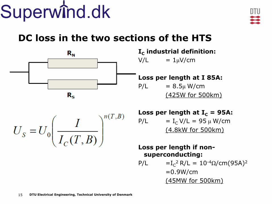
DC loss in the two sections of the HTS
IC industrial definition:
V/L = 1μV/cm
Loss per length at I 85A:
P/L = 8.5μ W/cm
(425W for 500km)
Loss per length at IC = 95A:
P/L = IC V/L = 95 μ W/cm
(4.8kW for 500km)
Loss per length if non-superconducting:
P/L =IC2 R/L = 10-4Ω/cm(95A)2
=0.9W/cm
(45MW for 500km)

16 DTU Electrical Engineering, Technical University of Denmark
Requirements for HTS machines in general
• Reliability of the cooling system, including
– Cryocoolers
– Possible rotating gaskets
– Redundancy
• Designed to withstand possible faults
– Mechanically rigid
– Thermally stabile
– Quenching must be avoided
• The same requirements for the stator as found in other machines
– Reliable cooling system
– Short circuit protection

17 DTU Electrical Engineering, Technical University of Denmark
Point of discussion
• Discuss with your neighbour (two and two):
– The presentation on HTS generators for wind turbines from yesterday
– What has been presented so far this afternoon
• Comments, questions, suggestions?

18 DTU Electrical Engineering, Technical University of Denmark
CONSIDERATIONS FOR LARGE SCALE OFFSHORE

19 DTU Electrical Engineering, Technical University of Denmark
Generations of wind turbine generators
lIBDP 2

20 DTU Electrical Engineering, Technical University of Denmark
1G wind turbine generator REpower 5MW
• Generator: Geared doubly fed induction generator

21 DTU Electrical Engineering, Technical University of Denmark
1G wind turbine generator Enercon E-126 6MW
• Generator: Direct drive wound field synchronous generator

22 DTU Electrical Engineering, Technical University of Denmark
2G wind turbine generator Multibrid M5000 5MW
• Generator: Hybrid geared permanent magnet generator

23 DTU Electrical Engineering, Technical University of Denmark
Active materials in the generators

24 DTU Electrical Engineering, Technical University of Denmark
1G – Iron and Copper

25 DTU Electrical Engineering, Technical University of Denmark
Ferromagnetic domains aligned in Fe

26 DTU Electrical Engineering, Technical University of Denmark
2G – NdFeB, Iron and Copper

27 DTU Electrical Engineering, Technical University of Denmark
RFeB permanent magnets (R = Rare earth)

28 DTU Electrical Engineering, Technical University of Denmark
3G – YBCO, Iron and Copper
• Rotor requires leads for the very stable DC supply (brushless?)
• Rotating cooling system or rotating gaskets
• Extremely high current densities leading to very high airgap flux densities
• Slotless designs are commonly proposed, such that B ~2.5T can be achieved
• SeaTitan (design by AmSC): P = 10MW, D~5m, L~5m, m = 150-180 tons

29 DTU Electrical Engineering, Technical University of Denmark
Behaviour of the superconductor
• Meissner effect
• The superconductor must be operated within the critical surface
• Critical engineering current densities:
• 2-3A/mm2 is common in conventional large machines
• 2-300A/mm2 can be achieved in HTS machines
insulationconductor
CCe
A
IJ
,

30 DTU Electrical Engineering, Technical University of Denmark
Materials for coated conductors (2G HTS tape)

31 DTU Electrical Engineering, Technical University of Denmark
Drivetrain comparison – Rare earth usage
mR = 0.27mR-B-Fe
Cu & Fe
PM HTS
Geared
0 25kgR/MW Have not
been proposed
Hybrid
0 45kgR/MW 20gR/MW
Direct drive
0 250kgR/MW 100gR/MW

32 DTU Electrical Engineering, Technical University of Denmark
Point of discussion
• Discuss with your neighbour (two and two):
– The difference between the drivetrains
– Your opinion on the HTS alternative, based on your experience and background
– What do you see as the biggest advantage?
– What do you see as the biggest challenge?
– How is this relevant for your company?
• Comments, questions, suggestions?

33 DTU Electrical Engineering, Technical University of Denmark
Advantages
• High torque density
• Less rare earth usage
• Less top mass => lighter structure
• Ease of transportation
• Efficiency
• Less lubricant

34 DTU Electrical Engineering, Technical University of Denmark
Challenges/Disadvantages
• Cooling
• Insulation
• Reliability of the cooling system
• Supply of components
• Immaturity of the technology/supply chain
• Cost!
• Cool down time
• Maintenance
• Short circuit
• Materials
• Failure modes
• Torque transmission
• Slip rings
35 DTU Electrical Engineering, Technical University of Denmark
Relevance for your company
• Size, logistics, material usage
• Makes for interesting research

36 DTU Electrical Engineering, Technical University of Denmark
Importance of cost of energy (CoE)
• CoE is reduced as the total installed capacity is increased
• 121GW (2008) – 215GW (June 2011)
Source: www.pwc.com/sustainability

37 DTU Electrical Engineering, Technical University of Denmark
CoE from renewable energy sources will become lower than from fossil fuel sources
Source: European Climate Foundation – Roadmap 2050

38 DTU Electrical Engineering, Technical University of Denmark
Danish Wind Industry Association MegaVind – 2020 Strategy
• Vestas Wind Systems
• Siemens Wind Power
• DONG Energy
• Grontmij
• Technical University of Denmark (DTU)
• Aalborg University
• Half CoE from offshore wind farms
• Achieved by:
– 25% increase in capacity factor
– 40% reduction in CAPEX
– 50% reduction in OPEX

39 DTU Electrical Engineering, Technical University of Denmark
MegaVind – 2020 Strategy 50% reduction in CoE from offshore wind
Source: Danish Wind Industry Association – MegaVind Strategy

40 DTU Electrical Engineering, Technical University of Denmark
MegaVind – 2020 Strategy Focus areas
Source: Danish Wind Industry Association – MegaVind Strategy
41 DTU Electrical Engineering, Technical University of Denmark
Point of discussion
• Discuss with your neighbour (two and two):
– Most important requirements for future offshore wind turbines
– or even wind farms
• List suggestions?
• Any that are not compatible with HTS machines?

42 DTU Electrical Engineering, Technical University of Denmark
EFFICIENCY AND POWER DENSITY

43 DTU Electrical Engineering, Technical University of Denmark
Generator Power
limited by stator cooling
limited by the power rating of the WT (around 10rpm at 10MW)
A/m000,70A
3m115MW10 PMVP
rad/s05.1
pVBATP gmm cosˆ2
3m42MW10 HTSVP
PM Generator Bg = 0.9T HTS Generator Bg = 2.5T
With an axial stack length of 2.0m, this would result in a airgap diameter of:
Dg = 8.6m Dg = 5.2m

44 DTU Electrical Engineering, Technical University of Denmark
Amount of copper in a PM and HTS
• If the electric loading (A/m circumference) and the armature current density is the same in both machines:
– Amount of copper will be proportional to the diameter
• Hence if a 10MW PM machine has
– 20 tons of copper and
– 8.6m airgap diameter
• A 10MW HTS machine will have
– 12 tons of copper at
– 5.2m airgap diameter
Diameter

45 DTU Electrical Engineering, Technical University of Denmark
Copper loss comparison
• The copper losses are the dominating losses in a large direct drive wind turbine generator
• The copper losses are:
• Using ρCu = 8950kg/m3, σCu =45MS/m, JCu = 2.7A/mm2 gives
• 360kW Cu losses in the PM (3.6% of rated output power)
• 220kW Cu losses in the HTS (2.2% of rated output power)
CuCuCu RIP2
CuCu
CuCuCu
A
lAJ
22
Cu
CuCu VJ
2

46 DTU Electrical Engineering, Technical University of Denmark
Cooling losses in an HTS machine
Previously we had:
425W for 500km
If additional 375W come from:
Conduction through connections
Radiation through the insulation
The total power to be removed needs to be 800W
In order to remove this at 30K, 50 times more power is needed:
40kW (0.40% of rated output power)
The total losses (excluding iron and mechanical) are therefore:
2.6% for HTS (efficiency excluding Fe and Mech: 97.4%)
3.6% for PM (efficiency excluding Fe and Mech: 96.4%)

47 DTU Electrical Engineering, Technical University of Denmark
Point of discussion
• Discuss with your neighbour (two and two):
– The simplistic approach to efficiency estimation
• Comments, questions, suggestions?
• Partial load
• Stray losses
• Mechanical retention

48 DTU Electrical Engineering, Technical University of Denmark
Why use Multi-Pole Generators?
• The converter is indifferent (to a certain extent)
• Power is independent of pole numbers
• Voltage is independent of pole numbers
• Traditionally: weight (and cost) savings!

49 DTU Electrical Engineering, Technical University of Denmark
Core Back Thickness
• The flux path is from one pole to the next.
cbacbcbcb dlBAB ˆ2ˆ2ˆ
pd rotorcb
1,
pd statorcb
1,
50 DTU Electrical Engineering, Technical University of Denmark
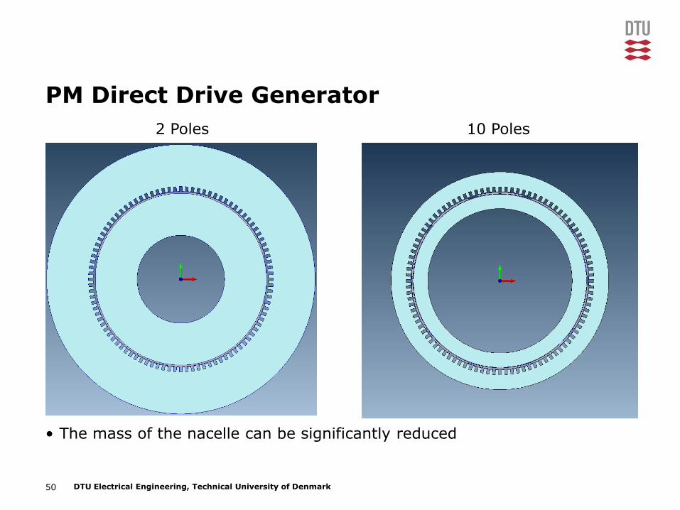
PM Direct Drive Generator
• The mass of the nacelle can be significantly reduced
2 Poles 10 Poles

51 DTU Electrical Engineering, Technical University of Denmark
End windings
• Copper and HTS end winding length is reduced
2 Pole Multi-Pole

52 DTU Electrical Engineering, Technical University of Denmark
Simplified calculations of HTS usage
Source: H. Ohsaki et al. “Electromagnetic Characteristics of 10 MW Class Superconducting Wind Turbine Generators”, ICEMS, 2010.

53 DTU Electrical Engineering, Technical University of Denmark
Estimating the effective airgap
• 12 pole, Dg = 5.2m, JCu = 2.7A/mm2, A = 70kA/m, FFCu = 50%
• Radial copper depth:
• Airgap: g = 10mm
• Cryostat thickness: 30mm each
• HTS radial thickness: 30mm
– iterative
• Each pole has 2.7m of heavily saturated iron. This can be simply represented by 50mm of air (corresponding to μr~50
• Total effective airgap: 200mm
mm505.0107.2
10703
3
Cud

54 DTU Electrical Engineering, Technical University of Denmark
Estimating the required number of turns
• 12 pole, Dg = 5.2m, JCu = 2.7A/mm2, A = 70kA/m, FFCu = 50%
• Effective airgap: 200mm
• If Bg = 2.5T → Hg = 2MA/m
• Required mmf per pole:
• If each HTS conductor can carry 100A then 4000 turns are needed
kA400
mmf
ldHmmf
mm505.0107.2
10703
3
Cud

55 DTU Electrical Engineering, Technical University of Denmark
Estimating the required length of HTS tape
• 12 pole, Dg = 5.2m, JCu = 2.7A/mm2, A = 70kA/m, FFCu = 50%
• HTS turns per pole: NHTS = 4,000
• Pole arc length
• As the HTS has circular ends the average turn length is:
• The total length of HTS tape in a 12 pole machine would therefore be:
•
m4.12
p
Dl
g
pole
m4.82 axialpoleturn lll
km4002 plNl turnHTSHTS

56 DTU Electrical Engineering, Technical University of Denmark
Mass, HTS length and price as a function of pole number

57 DTU Electrical Engineering, Technical University of Denmark
Power density
• The power density of an HTS generator can therefore be expected to be higher than for a PM generator
• The power density will depend on the specific design and varies in the literature
• Most scientific papers do not account for the entire mass of the generator
• AmSC promise 15-18kg/kW (10MW)
• A 10MW PM generator might have 30kg/kW (Bang 2008)
(D. Bang et al. “Review of generator systems for direct-drive wind turbines”, EWEC 2008)

58 DTU Electrical Engineering, Technical University of Denmark
Point of discussion
• Discuss with your neighbour (two and two):
– The simplistic assessment of the HTS tape usage
• Comments, questions, suggestions?
59 DTU Electrical Engineering, Technical University of Denmark
ASSESSING THE CURRENT COST SITUATION

60 DTU Electrical Engineering, Technical University of Denmark
Cost of HTS tape
• If 500km of HTS tape is assumed for a 10MW wind turbine generator
• The current carrying capacity is 100A and the cheapest price on the market is €100/kAm, which gives €10/m
• The cost of the HTS tape for a 10MW would therefore be €5 million
• In addition the cryostat, cryocooler etc. will have to be added
• PM price today? €100-200/kg
• If 10 tons of PM is required for a 10MW wind turbine
• The cost of the PM for a 10MW would be €1-2 million

61 DTU Electrical Engineering, Technical University of Denmark
Future cost of HTS must/will come down
• It is not unlikely that the price of HTS tape will come down to €15/kAm
• This would result in €750,000, if 500km of HTS tape was required for a 10MW wind turbine
• This would be competitive with PM technology

62 DTU Electrical Engineering, Technical University of Denmark
BECOMING COMMERCIALLY VIABLE

63 DTU Electrical Engineering, Technical University of Denmark
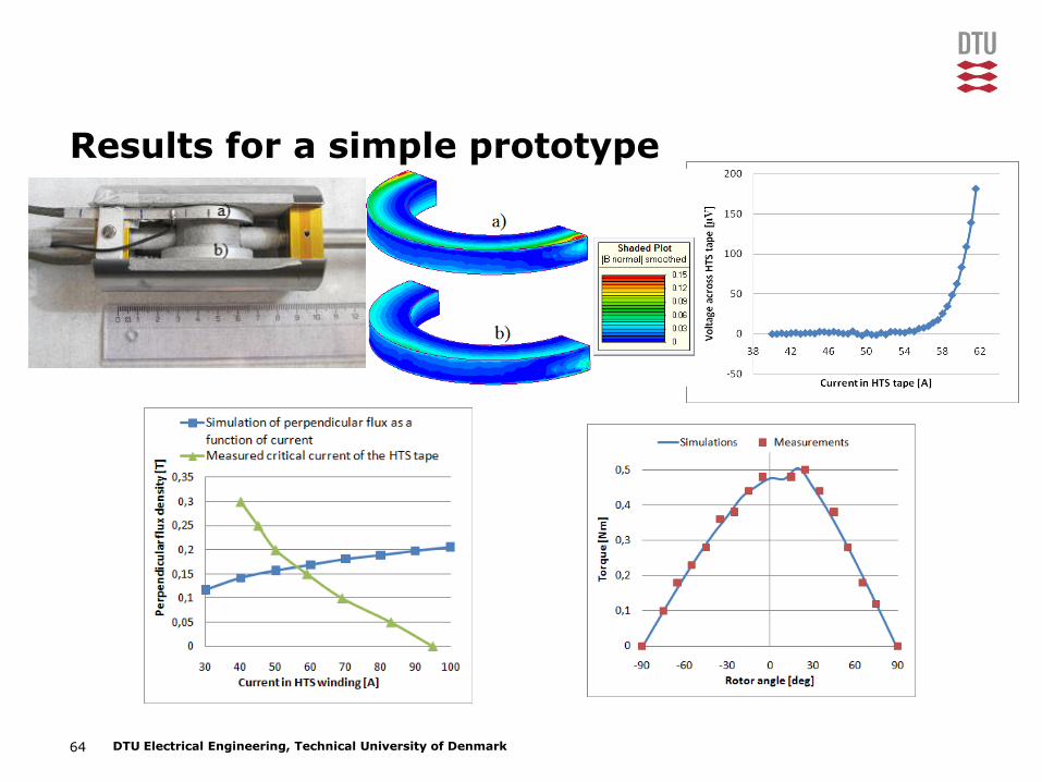
Continue research in universities
• Building small scale prototypes
• Learning from these and extrapolating to large scale
64 DTU Electrical Engineering, Technical University of Denmark
Results for a simple prototype

65 DTU Electrical Engineering, Technical University of Denmark
Design and construct large scale demonstrators
• AmSC and Northrop-Grumman (NGC) built a 36.5MW for the US Navy in 2007
• AmSC and Converteam built a 5MW for the US Office of Naval Research in 2005
• AmSC would like to build the SeaTitan – a 10MW direct drive wind turbine generator
• Converteam and Zenergy built a small HTS hydrogenerator
• Converteam are building an 8MW direct drive wind turbine generator
• Siemens has had much HTS machine activity
• GE just announced that they would construct a 10MW direct drive wind turbine generator based on LTS

66 DTU Electrical Engineering, Technical University of Denmark
Collaboration and commitment is needed
• Collaboration and commitment is needed from the
– Wind turbine manufacturers
– HTS tape manufacturers
– Wind turbine operators
• Commitment is needed from the funding bodies
– This seems to be in place – HTS generators for wind turbines have been mentioned specifically in an FP7 call
• Mass production of the HTS tape is required
– Avoid the chicken and egg scenario

67 DTU Electrical Engineering, Technical University of Denmark
THANK YOU! QUESTIONS?

68 DTU Electrical Engineering, Technical University of Denmark
This presentation is part of an EU Interreg project, which is informing about projects connected to Wind in the Øresund-region of Eastern Denmark and Southern Sweden. A collaboration between the Technical University of Denmark (DTU) and The Faculty of Engineering at Lund University (LTH).
VIND I ØRESUND