High-Pressure Annular Seal Leakage and...
10
International Journal of Rotating Machinery, 8(6): 403–411, 2002 Copyright c 2002 Taylor & Francis 1023-621X/02 $12.00 + .00 High-Pressure Annular Seal Leakage and Rotordynamics with Application to Turbomachinery D. Rame Gowda and B. S. Prabhu Machine Dynamics Laboratory, Department of Applied Mechanics, Indian Institute of Technology, Madras, Chennai, India The paper presents theoretical investigations that deal with the steady state mass flow rate, labyrinth seal-influence coefficients, and unbalance response of a cryogenic turbo- pump. A numerical method for calculating the leakage flow rates, stiffness, and damping coefficients of liquid hydrogen– lubricated seals is presented. Rotation and seal surface roughness effects are also included for leakage and dynamic force calculation. A finite element solution of a Reynolds equation is obtained for steady state as well as dynamic pres- sure distributions produced by a small amplitude whirl of the seal journal center (a first order perturbation solution). Film rupture is taken into account with the boundary to the ruptured film zone determined by an iterative procedure. A brief procedure is presented for modeling of the rotor/seals system. This work extends the previous theory for plain centered seals to large eccentricities using a perturbation analysis, which includes surface roughness effects. Investi- gations have been carried out for seal breadth-to-diameter ratio (BDR) of 0.25 to 0.5. The performance of a convergent and three-stepped seal is estimated. Numerical data for these seals for an eccentricity ratio up to 0.8 has been obtained. Keywords Rotating machinery; Reynolds equation; Seal leakage; Finite-element perturbation approach; Computational fluid dynamics; Rotordynamic coefficients; Stability and unbalance response Design calculations of the dynamic behavior of rotors rely on an accurate representation of the dynamic characteristics of the rotor/seals. Annular controlled leakage seals have been Received 5 July 2000; accepted 13 July 2001. Address correspondence to Dr. B. S. Prabhu, Machine Dynamics Laboratory, Applied Mechanics Department, Indian Institute of Tech- nology, Madras, Chennai 600-036, India. employed in the space shuttle main engine (SSME) high-pressure fuel turbo pump (HPFTP) to improve stability. Seals for liq- uids with low kinematic viscosity, such as steam, hydraulic oil, and liquid hydrogen often have Reynolds number well above 2000. They tend to produce large seal stiffness and damping coefficients that can be beneficial to rotor stability. Hydrody- namic forces generated in these seals can drive a machine un- stable or contribute strongly to the stability of another machine. Furthermore, the fluid flow dynamics in a seal can have dra- matic effect on vibration of rotating machinery. Previous re- views of seal-rotordynamics indicate that large subsynchronous vibrations were encountered in tests of the space shuttle main cryogenic engine high-pressure fuel turbo pump (HPFTP) with labyrinth seals and the original shaft bearing supports (Black, 1969; Black and Jenssen, 1971; Allaire, Lee, and Gunter, 1978). Literature review shows several see-through and step labyrinth seal flow analyses involved simple correlation but no rotational effects on seal flow. Yamada (1962) experimentally measured the friction factor for axial Reynolds number up to 10 4 and gave the formula for laminar and turbulent flow. Those equa- tions relied on Blasius-type friction factors. Koeing and Bowly (1972) introduced the computer as a design tool in their arti- cle. They provide a computer program based on Egli’s (1935) method, which pinpoint the important design parameters for var- ious labyrinth configurations. Further, the kinetic energy carry over factor (or equivalent) is typically not well known for new designs (Rhode and Hibbs, 1993). On the other hand, seal-rotordynamic coefficients are re- quired for correlation of high-speed test measurements. These coefficients depend on a host of non-dimensional parameters, like length-to-diameter ratio (b/d), pressure ratio (P u /P d ), as- pect ratio, H g /c, and c/r, etc. Black, 1969; Black and Jenssen, 1971 first explained the influence of seal forces on the rotor- dynamic behavior of pumps. Allaire, Lee, and Gunter (1978) extended previous theories for short plain centered seals to large eccentricities using a perturbation analysis. However, the anal- ysis was performed in a stationary reference frame that ig- nores rotational effects. Childs (1981) traces the development of 403
-
Upload
phungduong -
Category
Documents
-
view
239 -
download
2
Transcript of High-Pressure Annular Seal Leakage and...

International Journal of Rotating Machinery, 8(6): 403–411, 2002Copyright c© 2002 Taylor & Francis1023-621X/02 $12.00 + .00
High-Pressure Annular Seal Leakage andRotordynamics with Application to Turbomachinery
D. Rame Gowda and B. S. PrabhuMachine Dynamics Laboratory, Department of Applied Mechanics, Indian Institute of Technology,Madras, Chennai, India
The paper presents theoretical investigations that dealwith the steady state mass flow rate, labyrinth seal-influencecoefficients, and unbalance response of a cryogenic turbo-pump. A numerical method for calculating the leakage flowrates, stiffness, and damping coefficients of liquid hydrogen–lubricated seals is presented. Rotation and seal surfaceroughness effects are also included for leakage and dynamicforce calculation. A finite element solution of a Reynoldsequation is obtained for steady state as well as dynamic pres-sure distributions produced by a small amplitude whirl ofthe seal journal center (a first order perturbation solution).Film rupture is taken into account with the boundary to theruptured film zone determined by an iterative procedure. Abrief procedure is presented for modeling of the rotor/sealssystem. This work extends the previous theory for plaincentered seals to large eccentricities using a perturbationanalysis, which includes surface roughness effects. Investi-gations have been carried out for seal breadth-to-diameterratio (BDR) of 0.25 to 0.5. The performance of a convergentand three-stepped seal is estimated. Numerical data for theseseals for an eccentricity ratio up to 0.8 has been obtained.
Keywords Rotating machinery; Reynolds equation; Seal leakage;Finite-element perturbation approach; Computationalfluid dynamics; Rotordynamic coefficients; Stability andunbalance response
Design calculations of the dynamic behavior of rotors relyon an accurate representation of the dynamic characteristicsof the rotor/seals. Annular controlled leakage seals have been
Received 5 July 2000; accepted 13 July 2001.Address correspondence to Dr. B. S. Prabhu, Machine Dynamics
Laboratory, Applied Mechanics Department, Indian Institute of Tech-nology, Madras, Chennai 600-036, India.
employed in the space shuttle main engine (SSME) high-pressurefuel turbo pump (HPFTP) to improve stability. Seals for liq-uids with low kinematic viscosity, such as steam, hydraulic oil,and liquid hydrogen often have Reynolds number well above2000. They tend to produce large seal stiffness and dampingcoefficients that can be beneficial to rotor stability. Hydrody-namic forces generated in these seals can drive a machine un-stable or contribute strongly to the stability of another machine.Furthermore, the fluid flow dynamics in a seal can have dra-matic effect on vibration of rotating machinery. Previous re-views of seal-rotordynamics indicate that large subsynchronousvibrations were encountered in tests of the space shuttle maincryogenic engine high-pressure fuel turbo pump (HPFTP) withlabyrinth seals and the original shaft bearing supports (Black,1969; Black and Jenssen, 1971; Allaire, Lee, and Gunter, 1978).Literature review shows several see-through and step labyrinthseal flow analyses involved simple correlation but no rotationaleffects on seal flow. Yamada (1962) experimentally measuredthe friction factor for axial Reynolds number up to 104 andgave the formula for laminar and turbulent flow. Those equa-tions relied on Blasius-type friction factors. Koeing and Bowly(1972) introduced the computer as a design tool in their arti-cle. They provide a computer program based on Egli’s (1935)method, which pinpoint the important design parameters for var-ious labyrinth configurations. Further, the kinetic energy carryover factor (or equivalent) is typically not well known for newdesigns (Rhode and Hibbs, 1993).
On the other hand, seal-rotordynamic coefficients are re-quired for correlation of high-speed test measurements. Thesecoefficients depend on a host of non-dimensional parameters,like length-to-diameter ratio (b/d), pressure ratio (Pu/Pd), as-pect ratio, Hg/c, and c/r, etc. Black, 1969; Black and Jenssen,1971 first explained the influence of seal forces on the rotor-dynamic behavior of pumps. Allaire, Lee, and Gunter (1978)extended previous theories for short plain centered seals to largeeccentricities using a perturbation analysis. However, the anal-ysis was performed in a stationary reference frame that ig-nores rotational effects. Childs (1981) traces the development of
403

404 D. R. GOWDA AND B. S. PRABHU
theoretical treatment of the dynamic behavior of high-pressureannular inter-stage seals. In 1982, Childs and Dressman testeda three-step interstage seal and reported lower stiffness coef-ficients by about 20%. On the basis of their results obtainedfor a three-step seal, and neglecting the added-mass and cross-coupled coefficients, they recommend for reduced modelingseals in rotordynamics analysis of pumps. Childs (1983 a, 1983b)predicted very good results for a finite length seal. They provideda comprehensive program for the analysis of turbulent annu-lar seals based on the Hirs (1973) turbulence bulk-flow modeland included inlet swirl velocity effects. Journal bearings arenormally cavitated. They are quite nonlinear, yielding rotordy-namic coefficients which are strongly dependent on the staticeccentricity ratio. Due to the absence of cavitation in seals, theorbit is assumed to be circular, and they may remain linear outstatic eccentricity ratio of about 0.5 (Childs, 1993). Hence, thecoefficients of equation of motion for small motion about a cen-tered position are generally satisfactory for the analysis of pumpseal-rotordynamics. In cryogenic turbopumps, seals are associ-ated with high pressures and flow rates and rotor speed up to45000 rpm. Navier Stokes momentum equations, the continuityequation, and the turbulence model (Simon and Frene, 1989)govern hybrid behavior of these seals.
In a real turbopump seal, the surface roughness varies from0.3 to 0.4 microns and having a slope of 10 to 12 degrees. Thisis an important parameter to be considered. Any isotropic sur-face has a two-dimesional roughness, and widely found in fine-machined surfaces. Christensen and Tonder (1973) and RamTuraga, Sekhar, and Majumdar (1998) gave the details of suchroughness structures. They showed the different trend in com-parison with respect to longitudinal and transverse roughness.In the sealing area fluid film has been divided into triangularelements. The fluidity matrices for three-node are evaluatedusing the procedure given in Reddi (1969) and Booker andHuebner (1972). The finite element formulation used in thepresent study is similar to one used by Kilt and Lund (1986) fora smooth seal, with necessary modifications. Allaire, Kokur, andNicholas (1984) developed a pressure parameter method for thefinite-element solution for Reynolds types equation. They haveconsidered two relative surface roughness values of 0.001 and0.01. The computer program developed by Chen and Jackson(1985) is more generalized and the output are in good agree-ment. Their computer code can also be used to obtain resultsof a three-step HPFTP-seal design that was modeled by AllaireLee, and Gunter (1978). Childs and Kim (1985) performed anexperimental test for a damper seal with different stator rough-ness patterns. Chen and Jackson (1987) developed a generalizedtheory for eccentric and misalignment effects in high-pressureannular seals. Nelson and Nguyen (1988a, 1988b) extended theperturbation technique to handle two-phase flows in seals andanalyzed the rotordynamic coefficients of incompressible flowswith a relative rough surface.
Scharrer and Nuez (1989) presented an analysis for an in-compressible flow in a centered annual seal with a deformed
surface. A redesign of the SSME HPFTP inter-stage seal as sep-arate pieces from the diffuser has brought into attention that,due to assembly and operating interferences, the resulting sealclearance is wavy in the axial direction instead of straight ortapered. Scharrer (1991) advanced a model for fixed-tilt an-nular seals and presented force coefficients for cryogenic sealapplication. San Andres (1991) has developed a CFD solutionfor plain seals using a bulk flow model with Moody-fiction-factor. He analyzed the dynamic forces of turbulent flow an-nular high-pressure wavy seals. San Andres solution compareswell with the predictions by Nelson and Nguyen (1988a, 1988b)over their calculated eccentricity range. As mentioned by Childs(1993), theoretical calculations with a code developed by SanAndres (1991) show a fairly good agreement, except forCxy,which is underestimated at high eccentricity ratios. However,San Andres’ code solves two-dimensional, bulk flow, incom-pressible, Navier Stokes equations to predict the static and rotordynamic characteristics of bearings and seals, in centered andeccentric positions. Rame Gowda, Sekhar, and Prabhu (1999)studied physical parameters of a straight through seal by usinga finite-element method (FEM). Their work consists of a com-bination of numerical and computational investigations. Theycompared labyrinth seal leakage flow parameter with measuredvalues of (Prasad, Manavalan, and Nanjundarao 1997), and pre-dicted using finite volume method (FLUENT). The results werein good agreement by about 10% with predicted values. Thedynamic coefficients are calculated with the empirical relationgiven by Kramer (1993).
The present work extends the theoretical treatment for plainand labyrinth seals to larger eccentricities and includes surfaceroughness effects. The continuity equation and momentum equa-tions are solved using a perturbation approach. An analysis ofabove cited turbopump is then used as an example to illustratethe application of the seal for rotating machinery stabilization.One can use the “Stochastic finite-element” model for isotropicsurfaces of annular roughened seals. Using this technique, itis possible to study the spatially randomly varying quantitiesof interest, such as variance and covariance of the rough sur-faces, in addition to the mean clearance values. A schematic viewof a rotor/seal eccentric position of seal geometry is shown inFigure 1.
FIGURE 1Coordinate system for seal analysis.

ANNUAL SEAL LEAKAGE AND ROTODYNAMICS 405
SEAL ANALYSISTwo-dimensional Reynolds equation governs the pressure
distribution of fluid in a seal can be written as,
∂
∂x
(h3∂p
∂x
)+ ∂
∂z
(h3∂p
∂z
)= 6ηr
(ω1− 2
∂φ
∂t
)∂h
∂x+ 12η
∂h
∂t[1]
Equation (1) when non-dimensionalized, the governing equationfor the pressure distribution of an incompressible fluid underdynamic condition can be written inθ − z coordinates in theform:
∂
∂θ
(h3∂ p
∂θ
)+(
d
b
)2∂
∂ z
(h3∂ p
∂ z
)= 6(1− 2φÄ)
∂ h
∂θ+ 12Ä
∂ h
∂T[2]
For a seal journal shown above, the following transformationsare made in Equations (1) and (2) as:x= r θ andU = rω. Theturbulence Reynolds-type equation that governs flow field in theclearance space of annular seal, which has been derived fromthe Equation (1) for the purpose of flow continuity as Allaireet al. (1984):
∂
∂x
(Gθ
∂p
∂x
)+ ∂
∂z
(Gz∂p
∂z
)= σ
2U∂H
∂x+ ∂H
∂t[3]
whereFx = H3/kxµ andFy= H3/kyµ.With reference to the straight-through seals, schematic
(Figure 1), the termskx andky includes the turbulent correctionfactors, such thatGθ andGz are similar but not identical. Aboveturbulent correction factors are derived from the Reynolds equa-tion for an incompressible fluid.
The rotor rotates at constant angular speedω about its axis. Itis assumed that the rotor undergoes a steady whirl in an ellipticorbit with a frequencyωp about its mean steady state position.The governing equation for a seal gives the fluid pressure dis-tribution, as a function ofε and φ. Assuming that the rotorwhirls about its mean steady state position given byε0 andφ0,the first order perturbations (which are generally valid for smalldisplacements) of the pressure and the local film thickness (withno misalignment) can be expressed as,
p = p0+ ε1eiT p1+ ε0φ1eiT p2 [4]
h = h0+ ε1eiT cosθ + ε0φ1eiT sinθ [5]
where
ε= ε1eiT + ε0, φ=φ1eiT +φ0, and ε1¿ ε0, φ1¿ φ0
The steady state film thickness is given byh0= 1+ ε0 cosθ,and H θ = 1+ ε0 cosθ + Hg/c for grooved surfaces. Substitut-ing Equation (4) to (5) in Equation (2) and (3) and collecting the
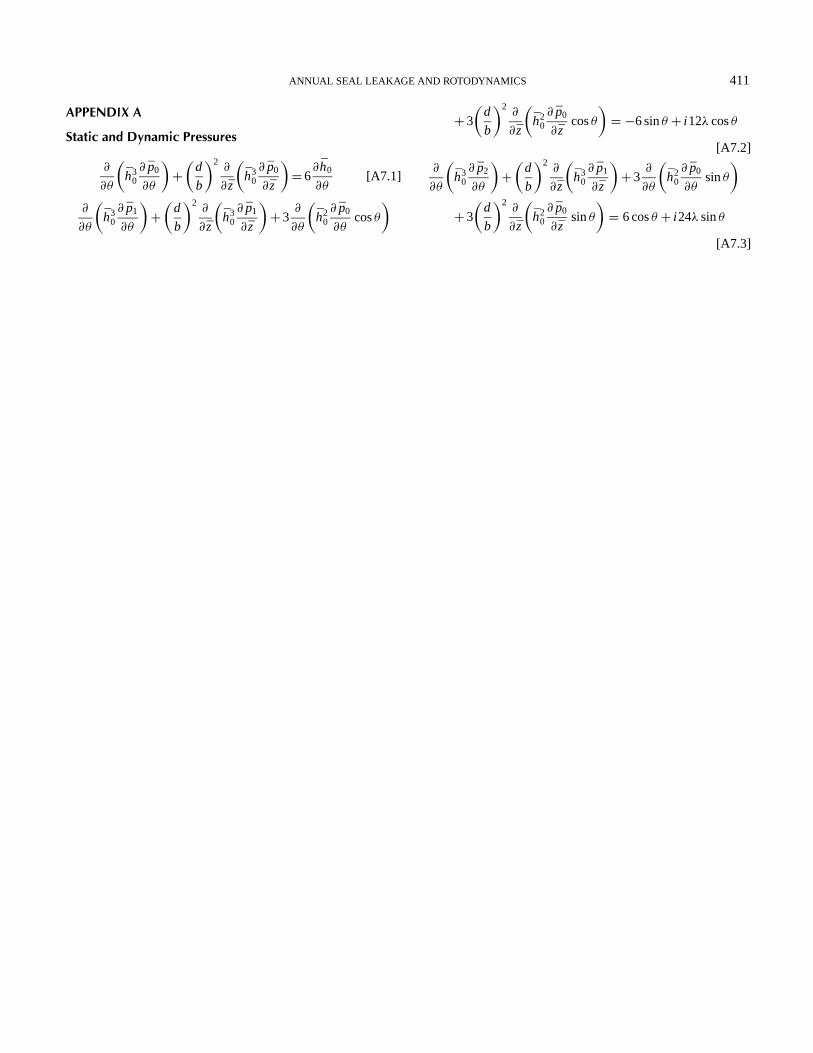
zeroth and first order terms forε1 andε0φ1, a 3-set of equationswere obtained for a seal. Using the finite element method, theseequations can be solved. Static and dynamic pressuresP0, P1,and P2 are obtained, which are given in Appendix A.
FINITE-ELEMENT FORMULATIONThe detailed finite element formulation for the stochastic
roughness modeling is as follows: Stationary values are foundif: ∂ I ( pi )/∂ pi = 0. In the interior of an element the pressure dis-tribution pi (θ, z) is expressed in terms of known polynomialsand unknown parametric values:
pei =n∑
k=1
NI j (θ, z) pi j [6]
where n is the number of element nodes and the indexjindicates the node number and the equivalent for stationary nodalvalues are ∂ I ( pi )/∂ pi j = 0. Substituting Equation (6)into Equation A7.1 to A7.3 and performing differentiation onthese equations yields static pressureP0, and perturbed (dy-namic) pressurespi = p2, which is the imaginary component.These three differential equations can be reduced to the form,
[K p]{ pi }= {Kui }, wherei = 0, 1, 2 [7]
The boundary conditions are as follow:P0= 0, whenθ = 0, 2πand other two sides the same holds good whenP0< 0, upstreamand downstream pressures are specified.P1 and P2 are madeequal to zero atθ and at nodes, whenP0 was equal to zero.
Isotropic Roughness Parameters for a SealOn perturbing equation (see Appendix A7.1 and A7.3), from
mean-steady-state position and repeating the procedure as de-scribed, one can obtain another set of equations considering sealroughness both (stator and rotor) as:
∂
∂θ
((h3
0+ 3σ 2h0) ∂ p0
∂θ
+(
d
b
)2∂
∂ z
((h3
0− 6σ 2h0)) ∂ p0
∂ z= 6
∂ h0
∂θ[8]
∂
∂θ
((h3
0+ 3σ 2h0) ∂ p1
∂θ+(
d
b
)2∂
∂ z
((h3
0− 6σ 2h0) ∂ p1
∂ z
+ 3∂
∂θ
((h2
0+ σ 2) ∂ p0
∂θcosθ
)+ 3
(d
b
)2∂
∂ z
((h2
0− 2σ 2) ∂ p0
∂ zcosθ
)=−6 sinθ + i 12Ä cosθ [9]
∂
∂θ
((h3
0+ 3σ 2h0) ∂ p2
∂θ+(
d
b
)2∂
∂ z
((h3
0− 6σ 2h0) ∂ p0
∂ z
+ 3∂
∂θ
((h2
0+ σ 2) ∂ p0
∂θsinθ
)

406 D. R. GOWDA AND B. S. PRABHU
+ 3
(d
b
)2∂
∂ z
((h2
0− 2σ 2) ∂ p0
∂ zsinθ
)=−6 cosθ + i 24Ä sinθ [10]
The above three sets of equations giveP0, P1, and P2,respectively, and these values are used for calculation of eightlinearized dynamic coefficients.
For the roughened surfaces, total mean film thickness is cal-culated using the expression,
H θ =1r (1+ ε cosθ )+ hs(θ, z, ζ ) [11]
where1r denotes the radial clearance andε the eccentricityratio. In general, in Equation (11) the right hand term is a func-tion of both space variablesθ andz, its random character beingindicated by the random variableζ . Its precise form dependsupon the structure of the surface roughness, the E ( ) operatoris given by the relation,E(g(H ))= ∫∞−∞ g(H ) f (hs)dhs wheref (hs) is the density function for the random variablehs. It hasbeen found convenient to use a polynomial approximation ratherthan the Gaussian distribution itself. Such a function is
f (hs)= 35(c2− h2
s
)3/32c7,−c≤ hs≤ c, = 0, elsewhere
[12]
This function terminates atc=±3σ whereσ is the standarddeviation. Whenh≈ 3σ (with in the hydrodynamic limit i.e.,h> 3σ ), these may influence the seal performance significantly.
Once finite element formulation is done, the final expressionsneglecting the squeeze term for the deterministic case using3-node linear triangular elements can be written as,
2[KP]{p}= [K P]{u}− {Q} [13]
[K P]=N∑
m=1
(bi bj + ci cj
48η12
)∫∫Hm
3d Am [14]
[Ku]=N∑
m=1
(bi + ci
21
)∫∫HmM j d Am [15]
{Q}=N∑
m=1
2∫
q Nmds [16]
Stochastic Finite-Element FormulationTaking the expected values from Equations (13) to (16) for
the rough surface seal, one can get the following equation,
2〈K P〉〈P〉= 〈Ku〉{u}− 〈Q〉 [17]
〈K p〉=N∑
m=1
(bi bj
12ηB2
)∫ ⟨H3
m
⟩dxm [18]
〈Ku〉=N∑
m=1
bi
B
∫〈Hm〉M j dxm [19]
Q is the same as in the deterministic case.H is a stochastic vari-able andu is deterministic variable, which are approximatedby interpolation functions.H has Gaussian or an approxima-tion to Gaussian distribution. The pressure boundary conditionsfor solving Equation (17) are the same as those for determin-istic finite element method and the flow is considered as linearnormal outward flow. Seal leakage flowm can be calculatedfrom ∫ (
Gx
η
(∂ p
∂y
)H3
g
)dx [20]
Unidirectional LoadWith reference to Figure 1, the hydrodynamic forces and the
steady-state characteristics are calculated from:
Fr =∫ 1
0
∫ 2∏
0p cosθ dθ dz,
Fφ =∫ 1
0
∫ 2∏
0p sinθ dθ dz,
W0 =√
F2r 0+ F2
φ0, and φ= tan−1(− Fφ0/Fε0).
Unidirectional applied load is assumed to be constant in bothmagnitude and direction and equal to the steady state load car-rying capacity, i.e.,W= W0. The equations of motion underthese conditions can be written as:
ε= εφ2+ Fr
MW0Ä2+ cosφ
MÄ2[21]
φ=−2εφ
ε+ Fφ
MW0Ä2+ sinφ
MÄ2[22]
Equations (21) and (22) are second-order differential equationsin ε andφ. These are solved by using the fourth-order Runge-Kutta method with the initial boundary condition ˙ε, φ= 0. Fromthis we get the eccentricity ratio, attitude angle, and their deriva-tives. These are used in the solution of the Reynolds equation forthe next time step to obtain the pressure distribution and, hence,
FIGURE 2(a) and (b) show a sectional seal configuration.

ANNUAL SEAL LEAKAGE AND ROTODYNAMICS 407
TABLE IRotodynamic coefficients and mass flow rate of different seals
Seal configuration/ Three-step rough Three-step labyrinth Three-step separated Present combinedDynamic seal values (Allaire seal prediction (Chen labyrinth seal model labyrinth sealcharacteristics et al., 1978) and Jackson, 1987) results values
Kxx/Kyy (MN/m) 6.96e7 7.696e7 3.096e7 7.980e7Kxy/Kyx (MN/m) 4.09e7 4.068e7 1.650e7 3.910e7Dxx/Dyy (N-s/m) 2.09e4 1.322e4 0.687e4 1.680e4Dxy/Dyx (N-s/m) 2.96e3 2.750e3 4.128e3 5.370e3Mass flow (Kg/s) 0.63 0.501 0.1819 0.1045
the fluid film forces components. The force components are thenused in the solution of the equation of motion. The procedureof solving the Reynolds equation and the equation of motion isrepeated until it completes the number of iterations.
Stiffness and Damping CoefficientsThe components of the dynamic seal load along the line of
centers and perpendicular to the lines of centers correspondingto the perturbed pressureε1 p1eiωpt can be written as
(Wd)r eiωpt =
1∫0
∫ θ2
θ1
ε1 p1r cosθ dθ dz,
and
(Wd)φeiωpt =1∫
0
∫ θ2
θ1
ε1 p1r sinθ dθ dz [23]
Again, since the seal journal executes small harmonic oscillationabout its steady state position in an elliptic orbit, dynamic loadcarrying capacity can be expressed as a spring force and a iso-viscous damping force as given below:
(Wd)r eiωpt = Krr cεr + Drr cεr
dεr
dt,
FIGURE 3Shows seal leakage versus pressure difference.
and
(Wd)φeiωpt = Kφr cεr + Dφr cεrdεr
dt[24]
Using Equation (24) in Equation (23), and integrating, the fol-lowing non-dimensional components of stiffness and dampingcoefficients result:K rr , K rφ, Drr , Drφ . Similarly, consideringdynamic displacements of the seal journal along theφ direc-tion, the other coefficientsK rφ, K φφ, Dφr , Dφφ can be writtenby analogy. InK i j the first suffix denotes the direction of theforce and the second suffix denotes the direction of displacementand forDi j the first and second suffix denote force and velocitydirections, respectively. As the dynamic pressure distributionsP1 and P2 have been obtained by finite element method, theabove eight coefficients can be obtained by integration.
SPACE SHUTTLE APPLICATION-CRYOGENIC PUMPThe seal geometry used in present analyses is taken from
Allaire, Lee, and Gunter (1978) and Chen and Jackson (1987)but with a reduced length-to-diameter ratio of 2:1. Figure 2(a)shows a three-step seal, which is existing in a high-pressure fuelTurbopump. Combined or integrated is as shown in Figure 2(b).The various data used in the present study areb= 0.02 m,d=0.04 m, c= 0.0000278 m, rpm= 37400, upstream pressure=120 bar, dynamic viscosity= 5.115× 10⁻⁵ N-s/m2, pressuredifference= 6 MPa, Temperature= 44 K, density of fluid=
FIGURE 4Shows direct stiffness coefficients versus eccentricity ratio.

408 D. R. GOWDA AND B. S. PRABHU
FIGURE 5Shows cross-coupled stiffness versus eccentricity ratio.
150 Kg/m3, Specific heat ratio= 2.2 and, liquid hydrogen is thetest fluid. The relative surface roughness of rotor= 0.51µm.
RESULTS AND DISCUSSIONThe numerical computation has been carried out for four
seals. A fine grid of 40× 20 (1600 elements) was used witha three-node triangular element. The dynamic characteristicsof the seal viz., stiffness, damping, and mass flow rates, havebeen obtained by using the finite-element perturbation method.The results presented in Table I shows the comparison of theseal-rotordynamic coefficients and mass flow rate for centeredseal. The results from present work corroborate well with theresults published by Allaire, Lee, and Gunter (1978), and Chenand Jackson (1987). The dynamic characteristics for a three-stepseparated labyrinth seal result are not satisfactory. But the otherthree labyrinth seals corroborate well. It has also been found thatthe combined labyrinth seal gives lower leakage when comparedwith other three seals. The combined seal has a lower flow rate,about 42% less as against the three-step labyrinth seal.
Figure 3 shows the variation in leakage versus pressure differ-ences. As the pressure drop increases, the leakage also increasessharply. From the present results, it is also clear that smallerclearance provide less leakage rates, which is necessary froma labyrinth seal working point of view. Since the present studyuses a positive clearance of 0.0556 mm, lower leakage rates are
FIGURE 6Shows direct damping coefficients versus eccentricity ratio.
FIGURE 7Shows cross-coupled damping coefficients versus eccentricity
ratio.
predicted as compared to Allaire, Lee, and Gunter (1978), andChen and Jackson (1987), which use slightly larger clearancesof 0.07 mm and 0.65 mm.
Figure 4 shows variation of the direct stiffness coefficientversus eccentricity ratio. It is observed that the direct stiffnesscoefficient values of four seals do not vary much with an eccen-tricity ratio up to 0.6. In the case of present seal models, stiffnessincreases moderately with increase in eccentricity ratio. Figure 5shows cross-coupled stiffness coefficients with eccentricity ra-tio. The coefficient values are well maintained up to 0.4 eccen-tricity ratio and thereafter there is a sharp increase. From Figure 6it is observed that the variation of direct damping coefficientswith respect to eccentricity ratio up to 0.5 is as expected. Beyond0.5 it increases sharply. The three-step separated and combinedseals show a sharp increase in damping coefficient with increasein eccentricity ratio. Figure 7 shows cross-coupled damping co-efficients also increase with increase in eccentricity ratio from0.2, for both separated and combined seals. The three-step sealsof Allaire, Lee, and Gunter (1978), and Chen and Jackson (1987)show similar trends up to 0.7 eccentricity ratio. Figure 8 showsthe variation of the whirl frequency ratio with static eccentric-ity ratio. Allaire’s rough seal maintains whirl frequency rationsalmost equal to 0.99 up to eccentricity ratio of 0.6. This showsthat it is operating in synchronized condition in that range. Sep-arated seal maintains steadily up to 0.5 whirl frequency ratio
FIGURE 8Shows whirl frequency ratio versus eccentricity ratio.

ANNUAL SEAL LEAKAGE AND ROTODYNAMICS 409
FIGURE 9Shows unbalance response at different speeds without
labyrinth seal.
with a negative sign, whereas combined seal sub-synchronizesup to 0.6 whirl frequency ratio and sharply decreases up to 0.8eccentricity ratio.
The numerical example has been carried out for a two-stageturbine rotor with a rotor-labyrinth seal using ROTORDYNA, acode developed by second author. Using the combined seal co-efficients, the unbalance response of a labyrinth seal for steady-state condition for various speeds is plotted in Figure 9 andFigure 10. Figure 9 shows the steady-state rotor response fordifferent speeds without a seal. The response in bothx and y-axes are shown for the above two cases. It is observed that theunbalance response amplitude is lower with a seal as shown inFigure 10. Using the above code, one can make a study of thetotal unbalance response of a turbopump model, which can havea number of labyrinth seals at different locations.
CONCLUSIONSA combined numerical-computational method was devel-
oped to account for grooved-surface-roughness treatments inthe rotor and stator of turbulent annular seals. A finite-elementanalysis has been carried out for labyrinth seals with low axialflow rates. The stiffness and damping of the seals have been cal-
FIGURE 10Shows unbalance response at different speeds with labyrinth
seal.
culated for wide range of eccentricity ratios. A combined sealhas been used as a numerical model considering the effects ofa uniformaly-distributed tooth height on rotor surface, which isdiffered in a step height by 1 mm. Four different seal configura-tions of the same length dynamic characteristics have been eval-uated. This work extends the concentric seal theories to coverthe seal leakage and dynamic coefficients with static eccentricityratios up to 0.8. Leakage results are consistent with the modelfor both the centered and fully-eccentric operations for all seals.Contrary to the seal eccentricity effect, the seal leakage increasesas the static eccentricity ratio increases. The seal rotor-dynamiccharacteristic changes significantly for a high eccentricity ratio,especially when the perturbation direction coincides with mini-mum clearance. For eccentric seals, the relationship between thedirect damping coefficients has been preserved up to 0.3 staticeccentricity ratio. Unbalance response shows that the amplitudeis lower when the seal coefficients are included.
NOMENCLATUREA labyrinth seal flow area (m2)b seal width (m)bi , bj coefficients of interpolation functionsc,1r radial clearance (m)Di j non-dimensional seal damping coefficients,Di j =
Dc3/ηr 3bd rotor diameter (m)e seal eccentricity (m)Gθ , Gz turbulence coefficientsH0= h(θ )+ hs(θ, z, ξ ) sum of a mean film thickness-
dimensionlessh(x, z) clearance function (m)h local film thickness,h0= 1+ ε0 cosθ + (Hg/c)Ki j non-dimensional seal stiffiness coefficients,Ki j =
Ki j c3/ηωr 3b[K p], [ Ku] assembled fluidity matricesM , M mass of rotor,M =mass parameter (M =Mcω2/
W0)m mass flow rateN interpolation polynomialn number of elementsP local hydrodynamic pressure (Pa)Pu upstream pressurePd downstream pressureP0, P1, P2 steady-state and perturbed (dynamic) pressures
(Pa)pi non-dimensional pressure,p= pc2/ηωr 2
Fr , Fφ hydrodynamic fluid film forces (N)Fr , Fφ non-dimensional fluid film forces,Fr = Fr c2/
φωr 3b and Fφ = Fφc2/ηωr 3br rotor radiusT dimensionless time,T =ωpt , wheret = time (s)U rotor peripheral speed (m/s)u, v, w mean velocity components of fluid inx, y andz
directions

410 D. R. GOWDA AND B. S. PRABHU
W0, W0 mean steady state load, steady-state loadW0=W0c2/ηωr 3b
σ slip coefficientξ entrance loss coefficientε, ε0 eccentricity ratio,ε= e/c, steady stateε0= e0/cη absolute viscosity of the fluid (Pa.s)θ , y, z non-dimensional coordinatesx, z, θ , z dimensionaless coordinates,θ = x/r, z= z/(b/2)Ä whirl ratio,Ä=ωp/ω
ρ0 density of fluidφ, φ0 attitude angle,φ0= steady-state attitude angle
(rad/s)ω,ωp angular velocity of rotor and angular velocity of
whirlε, φ first order derivatives with respect to time
REFERENCESAllaire, P., Lee, C., and Gunter, E. 1978. Dynamics of short eccentric
plain seals with high axial reynolds numbers.Journal of Spacecraftand Rockets15(6):341–347.
Allaire, P. E., Kocur, J. A., and Nicholas, J. C. 1984. A pressure-parameter method for finite-element solutions of reynolds’ equation,ASLE Transactions28(2):150–158.
Black, H. F. 1969. Effects of hydraulic forces in annular pressure sealson the vibrations of centrifugal pump rotors.Journal of MechanicalEngineering Science11(2):206–213.
Black, H. F., and Jenssen, D. 1971. Effects of high-pressure ring sealson pump rotor vibrations,ASME Paper No. 71-WA/FE-38.
Booker, J., and Huebner, K. 1972. Application of finite element methodsto lubrication: An engineering approach.Transactions of the ASME,Journal of Lubrication Technology24(2):313–323.
Childs, D. W., and Dressman, J. B. 1982. Testing of turbulent sealsfor rotordynamic coefficients, rotordynamic instability problemsin high performance turbomachinery. NASA CP 2250.Proceed-ings of a workshop held at Texas A&M University, May 10–12:157–171.
Childs, D. W. 1983a. Dynamic analysis of turbulent annular seals basedon hirs lubrication equation.Transactions of the ASME, Journal ofLubrication Technology105(3):429–436.
Childs, D. W. 1983b. Finite-Length solutions for rotordynamic coeffi-cients of turbulent annular seals.Transactions of the ASME, Journalof Lubrication Technology105(3):437–445.
Childs, D. W., and Kim, C. H. 1985. Analysis and testing for rotor-dynamic coefficients of turbulent annular seals with different, di-rectionally, homogeneous surface-roughness treatment for rotor andstator elements.Transactions of the ASME, Journal of Tribology107(3):296–306.
Chen, W. C., and Jackson, E. D. 1985. Eccentricity and misalignment ef-fects on the performance of high-pressure annular seals.ASLE Trans-actions28(1):104–110.
Chen, W. C., and Jackson, E. D. 1987. A generalized theory for eccen-tric and misalignment effects in high-pressure annular seals.ASLETransactions30(3):293–301.
Childs, D. W. 1993.Turbomachinery rotordynamics: phenomena, mod-eling and analysis. New York: Wiley Interscience.
Egli, A. 1935. The leakage of steam through labyrinth seals.Transac-tions of ASME57:115–122.
Hirs, G. G. 1973. A bulk-flow theory for turbulence in lubricantfilms. Transactions of the ASME, Journal of Lubrication Technol-ogyApril:137–146.
Klit, P., and Lund, J. W. 1986. Calculation of dynamic coefficients ofa journal bearing using a variation approach.Transactions of theASME, Journal of Tribology108:421–425.
Koeing, H. A., and Bowley, W. W. 1972. Labyrinth seal analysis.Transactions of the ASME, Journal of Lubrication Technology94:5–11.
Kramer, E. 1993. Dynamics of rotors and foundations. New York,Springer-Verlag, Chapter 10:143–159.
San Andres, Luis A. 1991. Analysis of variable fluid properties, turbu-lent annular seals.Transactions of the ASME, Journal of Tribology113:694–702.
Nelson, C. C., and Nguyen, D. T. 1988a. Analysis of eccentric annu-lar incompressible seals: Part 1-A new solution using fast fouriertransforms for determining hydrodynamic forces.Transactions ofthe ASME, Journal of Tribology110:354–360.
Nelson, C. C., and Nguyen, D. T. 1988b. Analysis of eccentric annu-lar incompressible seals: Part 2, Effect of eccentricity on rotordy-namic coefficients.Transactions of the ASME, Journal of Tribology110:361–366.
Prasad, B. V. S. S. S., Manavalan, V. Sethu, and Nanjunda rao, N. 1997.Computational and experimental investigations of straight-throughlabyrinth seals.42nd ASME Gas Turbine Aeroengine Congress,Turbo Expo.97, June 2–5, Orlando, Florida, USA, ASME Paper-97No. GT 326.
Reddi, M. M. 1969. Finite element solution of the incompressiblelubrication problem.ASME Journal of Lubrication Technology91(3):524–533.
Rhode, D. L., and Hibbs, R. I. 1993. Clearance effects on correspondingannular and labyrinth seal flow leakage characteristics.Trans. of theASME, Journal of Tribology115, October:699–704.
Ram Turaga, Sekhar, A. S., and Majumdar, B. C. 1998. Stability analysisof a rigid rotor suported on hydrodynamic journal bearings withrough surfaces; using the stochastic finite element method.Proc.Instn. Mech. Engrs212, Part J:121–130.
Rame Gowda, D. P., Sehkar, Chandra, and Prabhu, B. S. 1999.Estimation of leakage and dynamic characteristics of labyrinth sealusing finite element method.Proceedings of the 2nd InternationalConference on Industrial Tribology, December 1–4, Hyderabad,India:146–153.
Scharrer, J. K., and Nunez, D. J. 1989. The SSME HPFTP wavy in-terstage seal: I-seal analysis.Proceedings of 1989 ASME VibrationsConference, Machinery Dynamics-Applications and Vibration Con-trol problems, DE-Vol. 18-2.
Scharrer, J. K. 1991. The effect of fixed rotor-tilt on the rotordy-namic coefficients on incompressible flow annular seals. ASME-STLE Conference, St. Louis.
Simon, F., and Frene, J. 1989. Static and dynamic characteristics ofturbulent annular eccentric seals: effect of convergent-tapered ge-ometry and variable fluid properties.Transactions of ASME, Journalof Tribology111:378–385.
Yamada, Y. 1962. Resistance of flow through an annulus with innerrotating cylinder.Bulletin, J.S.M.E. 5(18):302–310.
ANNUAL SEAL LEAKAGE AND ROTODYNAMICS 411
APPENDIX A
Static and Dynamic Pressures
∂
∂θ
(h3
0∂ p0
∂θ
)+(
d
b
)2∂
∂ z
(h3
0∂ p0
∂ z
)= 6
∂ h0
∂θ[A7.1]
∂
∂θ
(h3
0∂ p1
∂θ
)+(
d
b
)2∂
∂ z
(h3
0∂ p1
∂ z
)+ 3
∂
∂θ
(h2
0∂ p0
∂θcosθ
)
+ 3
(d
b
)2∂
∂ z
(h2
0∂ p0
∂ zcosθ
)= −6 sinθ + i 12λ cosθ
[A7.2]
∂
∂θ
(h3
0∂ p2
∂θ
)+(
d
b
)2∂
∂ z
(h3
0∂ p1
∂ z
)+ 3
∂
∂θ
(h2
0∂ p0
∂θsinθ
)+ 3
(d
b
)2∂
∂ z
(h2
0∂ p0
∂ zsinθ
)= 6 cosθ + i 24λ sinθ
[A7.3]

International Journal of
AerospaceEngineeringHindawi Publishing Corporationhttp://www.hindawi.com Volume 2010
RoboticsJournal of
Hindawi Publishing Corporationhttp://www.hindawi.com Volume 2014
Hindawi Publishing Corporationhttp://www.hindawi.com Volume 2014
Active and Passive Electronic Components
Control Scienceand Engineering
Journal of
Hindawi Publishing Corporationhttp://www.hindawi.com Volume 2014
International Journal of
RotatingMachinery
Hindawi Publishing Corporationhttp://www.hindawi.com Volume 2014
Hindawi Publishing Corporation http://www.hindawi.com
Journal ofEngineeringVolume 2014
Submit your manuscripts athttp://www.hindawi.com
VLSI Design
Hindawi Publishing Corporationhttp://www.hindawi.com Volume 2014
Hindawi Publishing Corporationhttp://www.hindawi.com Volume 2014
Shock and Vibration
Hindawi Publishing Corporationhttp://www.hindawi.com Volume 2014
Civil EngineeringAdvances in
Acoustics and VibrationAdvances in
Hindawi Publishing Corporationhttp://www.hindawi.com Volume 2014
Hindawi Publishing Corporationhttp://www.hindawi.com Volume 2014
Electrical and Computer Engineering
Journal of
Advances inOptoElectronics
Hindawi Publishing Corporation http://www.hindawi.com
Volume 2014
The Scientific World JournalHindawi Publishing Corporation http://www.hindawi.com Volume 2014
SensorsJournal of
Hindawi Publishing Corporationhttp://www.hindawi.com Volume 2014
Modelling & Simulation in EngineeringHindawi Publishing Corporation http://www.hindawi.com Volume 2014
Hindawi Publishing Corporationhttp://www.hindawi.com Volume 2014
Chemical EngineeringInternational Journal of Antennas and
Propagation
International Journal of
Hindawi Publishing Corporationhttp://www.hindawi.com Volume 2014
Hindawi Publishing Corporationhttp://www.hindawi.com Volume 2014
Navigation and Observation
International Journal of
Hindawi Publishing Corporationhttp://www.hindawi.com Volume 2014
DistributedSensor Networks
International Journal of