High frequency Soft Switching Half Bridge Series...
8
General rights Copyright and moral rights for the publications made accessible in the public portal are retained by the authors and/or other copyright owners and it is a condition of accessing publications that users recognise and abide by the legal requirements associated with these rights. • Users may download and print one copy of any publication from the public portal for the purpose of private study or research. • You may not further distribute the material or use it for any profit-making activity or commercial gain • You may freely distribute the URL identifying the publication in the public portal If you believe that this document breaches copyright please contact us providing details, and we will remove access to the work immediately and investigate your claim. Downloaded from orbit.dtu.dk on: Jun 06, 2018 High frequency Soft Switching Half Bridge Series-Resonant DC-DC Converter Utilizing Gallium Nitride FETs Nour, Yasser; Knott, Arnold; Petersen , Lars Press Published in: Proceedings of the 19th European Conference on Power Electronics and Applications Publication date: 2017 Document Version Peer reviewed version Link back to DTU Orbit Citation (APA): Nour, Y., Knott, A., & Petersen , L. P. (2017). High frequency Soft Switching Half Bridge Series-Resonant DC- DC Converter Utilizing Gallium Nitride FETs. In Proceedings of the 19th European Conference on Power Electronics and Applications IEEE.
Transcript of High frequency Soft Switching Half Bridge Series...

General rights Copyright and moral rights for the publications made accessible in the public portal are retained by the authors and/or other copyright owners and it is a condition of accessing publications that users recognise and abide by the legal requirements associated with these rights.
• Users may download and print one copy of any publication from the public portal for the purpose of private study or research. • You may not further distribute the material or use it for any profit-making activity or commercial gain • You may freely distribute the URL identifying the publication in the public portal
If you believe that this document breaches copyright please contact us providing details, and we will remove access to the work immediately and investigate your claim.
Downloaded from orbit.dtu.dk on: Jun 06, 2018
High frequency Soft Switching Half Bridge Series-Resonant DC-DC Converter UtilizingGallium Nitride FETs
Nour, Yasser; Knott, Arnold; Petersen , Lars Press
Published in:Proceedings of the 19th European Conference on Power Electronics and Applications
Publication date:2017
Document VersionPeer reviewed version
Link back to DTU Orbit
Citation (APA):Nour, Y., Knott, A., & Petersen , L. P. (2017). High frequency Soft Switching Half Bridge Series-Resonant DC-DC Converter Utilizing Gallium Nitride FETs. In Proceedings of the 19th European Conference on PowerElectronics and Applications IEEE.

High frequency Soft Switching Half Bridge Series-Resonant DC-DC Converter Utilizing Gallium Nitride FETs
Yasser Nour, Arnold Knott Lars Press Petersen TECHNICAL UNIVERSITY OF DENMARK
Elektrovej, Building 325 2800 Kgs. Lyngby, Denmark ynour, [email protected]
ICEPOWER A/S Vandtårnsvej 62
2860 Søborg, Denmark [email protected]
Acknowledgements
This work has been carried out in the department of electrical of engineering, Technical University of Denmark (DTU). This work is a part of TinyPower project which is funded by Innovation Fund (No. 67-2014-1).
Keywords
Gallium Nitride FETs, High-Frequency Converters, Soft-Switching, Class-DE Inverter
Abstract The need for efficient, smaller, lighter and cheaper power supply units drive the investigation of using high switching frequency soft switching resonant converters. This work presents an 88% efficient 48V nominal input converter switching at 6 MHz and output power of 21 Watts achieving power density of 7 W/cm3 for Power-over-Ethernet LED lighting applications. The switching frequency is used to control the output current delivered to the load resistance. The converter was tested using a constant resistance load. The performance and thermal behavior were investigated and reported in this work.
Introduction
Using high switching frequency (3 – 30 MHz) is one method to achieve smaller and lighter power converters [1, 2, 3]. To achieve efficient operation of the switches, soft switching techniques need to be used specially with elevated input voltages. Resonant converters allow the utilization of soft switching techniques due to the intrinsic alternating behavior of current and voltage through the switches. Soft switching is needed not only to achieve high efficiency but it also reduces electromagnetic interference (EMI) levels [4]. For LED lighting applications, a resonant converter serves the need for a constant current source. The resonant circuit can be designed to supply a constant current at the selected switching frequency. The switching frequency then can be used as a control parameter for the output current. Resonant converters are relaying on exciting a resonant network to achieve power processing. Resonant DC-DC converters fundamentally consist of three stages. The first stage is to convert the DC input to an AC output. The second stage is the resonant circuit which can be modeled as an AC to AC converter stage. Combining the first and the second stages, results in an inverter circuit which converters a DC input to a desired level AC output. The third stage is the rectifier stage where energy is tapped off the resonant network to feed the output load [5]. A block diagram of the basic resonant DC-DC converter is shown in figure 1. The basic inverter topologies are class E and class D. In class E based inverter, the voltage stress across the switches can be 3.5 to 4 times higher than the input supply voltage which will force to use devices with much higher breakdown voltages [6, 7, 8, 9, 10]. Class D inverter utilizes two switches with voltage stress equal to the input voltage which allows using higher speed, lower voltage devices

[9, 11]. Using two switches requires precise design of the gate driver circuitry to avoid cross conduction trough the two switches which may cause catastrophic failure of the converter. Many other inverter topologies also can be used but they involve extra circuit components to solve the problem of high voltage stress on the switches [9, 12]. This paper utilizes a soft switching half bridge series resonant converter to realize a high frequency DC-DC converter using gallium nitride (GaN) switches. The rectifier circuit also needs to be designed to be in the soft switching operation mode to avoid excess power losses and keeping the high efficiency of the entire system. A Power-over-Ethernet (PoE) powered device (PD) can be designed to have an input voltage between 37 to 57 VDC to support both PoE (IEEE 802.3af) and PoE+ (IEEE 802.3at). The PD can draw power up to 25.5 W according to the IEEE802.at standard or 12.95 W according to IEEE802af [13]. The proposed converter is intended to be used for PoE LED lighting applications. The output power delivered to the LED string can be controlled via the switching frequency. The converter specifications are summarized in table 1.
Fig. 1: Basic block diagram of a resonant converter Table 1 : Converter Specifications
Power Stage Design
A soft switching half bridge series resonant converter is shown in figure 2. Following the design steps in [4], the ideal design surface can be calculated using the following steps. The input resistance of an ideal half wave rectifier can be calculated using equation 1 according to [4]
Where Rload is the load resistance (50 Ω) – used as a test load.
(1)
Then the inverter’s loaded quality factor can be calculated using equation 2 [4]
Where L is the inductance of the resonant tank, C is the capacitance of the resonant tank, and Rin_rec is the input resistance of the rectifier
(2)
Parameter Symbol Value Unit
Input Voltage Range VIN 37-57 V
Max. Output Power POUT_MAX 21 W
Power Density ≥ 4 W/cm3
Max. Output Voltage VOUT_MAX 30 V

The total voltage conversion ratio for the converter can be calculated using equation 3 [4]
Where ωn is the normalized switching frequency and QL is the inverter loaded quality factor
(3)
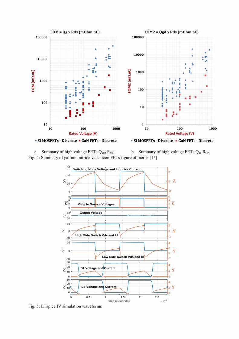
The total voltage conversion ratio or voltage gain is plotted versus the loaded quality factor and the normalized frequency in figure 3. The rectifier is a half wave rectifier implemented using low forward voltage schottky diodes connected to the load resistance. Gallium nitride FETs show superior performance compared to silicon counterparts. A comparison based on datasheet parameters was reported in [14, 15] and shown in figure 4. The inverter is designed using EPC8010 gallium nitride FETs [16] from EPC driven by an LM5113 [17] half bridge gate driver from Texas Instruments, a 4.7 nF ceramic capacitor and a 491 nH AT536RATR49_SZ [18] air-core inductor from Coilcraft. The load resistance is set to 50 Ohms as a first order approximation to the LED string. Based on the analysis and calculations, the converter is simulated using LTspice IV. Simulation results for the converter switching at 7 MHz and delivering around 15 Watts to the load are shown in figure 5. The output voltage is shown in the third subplot and it is 27.1 V.
Fig. 2: Half Bridge series resonant converter
Fig. 3: Voltage Gain vs. Loaded Quality Factor and Normalized Switching frequency
a. Summary of high voltage FETs Qgtot.RON b. Summary of high voltage FETs Qgd.RON Fig. 4: Summary of gallium nitride vs. silicon FETs figure of merits [15]
Fig. 5: LTspice IV simulation waveforms

Experimental Results The converter is implemented and assembled on a two layer printed circuit board. The converter can operate at switching frequencies between 5 MHz and 8 MHz. The converter operation was continuously monitored using a thermal camera to fine tune the dead-time between the switches to achieve soft switching operation. To do so, the dead-time was manually fixed at a point where the average temperature of GaN FETs is minimized. Figure 6 shows a photograph of the prototype power stage.
Figure 6: A Photograph of the test printed circuit board
The converter was tested for input voltages between 37 V and 57 V. Thermal photographs for three different input voltages for the converter switching at 6 MHz are shown in figure 7. The images show a maximum temperature of 89.8 C. The gate driver was detected to be the hottest element in the circuit.
(a) VIN = 37 V, FSW= 6 MHz (b) VIN = 48 V, FSW= 6 MHz (c) VIN = 57 V, FSW= 6 MHz
Figure 7: Thermal images for the converter prototype Due to the probe capacitance, measuring the switching node voltage while the converter is operating is shifting the operating condition. For sake of checking the switching performance, two sample waveforms were captured at two different frequencies. Figure 8a shows the switching node voltage when the input voltage of the converter is set to 57 V and switching frequency of 6 MHz. Figure 8b is the switching node voltage when input voltage is set to 37 V and switching frequency of 8 MHz. The switching node voltage waveforms were measured using a 2 GHz bandwidth oscilloscope and 500 MHz, 10x voltage probe with 9 pF capacitance. The converter’s output power and efficiency versus input voltage are shown in figure 9 at two different switching frequencies. The peak efficiency of the converter switching at 6 MHz is 88% converting 57 V input voltage to 34 V output voltage and delivering 23 W to the 50 Ω resistive load. On the other hand, the peak efficiency at 8 MHz switching frequency was measured to be 82.2% converting 57 V

input voltage to 24.7 V and delivering 12 W to the load. Using the switching frequency as a control variable to choose the desired output current is investigated and the results are shown in figure 10. The figure shows the converter output current and efficiency versus switching frequency variation between 5 MHz and 8 MHz. the load was fixed to 50 Ω during all measurements.
(a) VIN = 57 V FSW = 6 MHz (b) VIN = 37 V FSW = 8MHz
Figure 8: Switching node voltage measurements
(a) FSW = 6 MHz (b) FSW = 8 MHz
Figure 9: Measured output power and efficiency versus input voltage of the prototype
(a) Output current versus Fsw (b) Efficiency versus Fsw
Figure 10: Measured output current and efficiency versus switching frequency with 50 Ω load

Conclusions In this study, gallium nitride FETs were tested to be used in a high switching frequency resonant DC-DC converter and they show promising results. Gate driver and dead time should be accurately fine-tuned on-the-fly not only to achieve high efficiencies but also to prevent hard switching from happening and causing a damage to the converter. The converter achieves 88 % efficiency when delivering a 21 W to the 50 Ohms load. The converter achieves a power density of 7 W/cm3.
References
[1] J. M. Rivas, O. Leitermann, Y. Han and D. J. Perreault, "A Very High Frequency DC–DC Converter Based on a Class Φ2 Resonant Inverter," IEEE Transactions on Power Electronics, vol. 26, no. 10, pp. 2980-2992, 2011.
[2] J. Delaine, P. O. Jeannin, D. Frey and K. Guepratte, "High frequency DC-DC converter using GaN device," in IEEE Applied Power Electronics Conference and Exposition (APEC), Orlando, FL, 2012.
[3] D. J. Perreault et al.,, "Opportunities and Challenges in Very High Frequency Power Conversion," in IEEE Applied Power Electronics Conference and Exposition, Washington, DC, 2009.
[4] D. C. Marian, K. Kazimierczuk, Resonant Power Converters, 2nd Edition ed., Wiley-IEEE Press, 2011.
[5] B. Mommano, "Resonant Mode Converter Topologies," Texas Instruments.
[6] K. Peng, "Class E resonant inverter optimized design for high frequency (MHz) operation using eGaN HEMTs," in IEEE Applied Power Electronics Conference and Exposition (APEC), Charlotte, NC, 2015.
[7] J. M. Rivas, Y. Han, O. Leitermann, A. Sagneri and D. J. Perreault, "A High-Frequency Resonant Inverter Topology with Low Voltage Stress," in IEEE Power Electronics Specialists Conference, Orlando, FL, 2007.
[8] A. Knott, T. M. Andersen, P.Kamby, J. A. Pedersen, M. P. Madsen, M. Kovacevic and M. A. E. Andersen, "Evolution of Very High Frequency Power Supplies," IEEE Journal of Emerging and Selected Topics in Power Electronics, vol. 2, no. 3, pp. 386 - 394, 2014.
[9] M. Madsen, A. Knott and M. A. E. Andersen, "Low Power Very High Frequency Switch-Mode Power Supply With 50 V Input and 5 V Output," IEEE Transactions on Power Electronics, vol. 29, no. 12, pp. 6569 - 6580, 2014.
[10] J. A. Pedersen, M. P. Madsen, A. Knott, and M. A. E. Andersen, "Self-oscillating galvanic isolated bidirectional Very High Frequency DC-DC converter," in IEEE Applied Power Electronics Conference and Exposition (APEC 2015), Charlotte, NC, 2015.
[11] M. P. Madsen, A. Knott, and M. A. E. Andersen, "Very high frequency half bridge DC/DC converter," in IEEE Applied Power Electronics Conference and Exposition (APEC 2014), Fort Worth, TX, 2014.
[12] Z. Kaczmarczyk, "High-Efficiency Class E, EF2 , and EF3 Inverters," IEEE Transactions on Industrial Electronics, vol. 53, no. 5, pp. 1584-1593, 2006.
[13] A. Makdessian, T. Hunyh, "PoE technology for LED lighting delivers benefits beyond efficiency," LEDs Magazine, pp. 59-62, 3 September 2015.
[14] Y. Nour, A. Knott, I. H. H. Jørgensen, "Investigating Enhancement Mode Gallium Nitride Power FETs in High Voltage, High Frequency Soft Switching Converters," in IEEE International Conference on Power electronics, machines and drives (PEMD 2016), Glasgow, 2016.
[15] Y. Nour, Z. Ouyang, A. Knott, and I. H. H. Jørgensen, "Design and Implementation of High Frequency Buck Converter Using Multi-Layer PCB Inductor," in The 42nd Annual Conference of IEEE Industrial Electronics Society (IECON 2016), Florence, Italy, 2016.
[16] Efficient Power Conversion, "EPC8010 – Enhancement Mode Power Transistor Datasheet," 2015.
[17] Texas Instruments, "LM5113 Datasheet 100 V 1.2-A / 5-A, Half-Bridge Gate Driver for Enhancement Mode GaN FETs," Texas Instruments, 2016.
[18] Coilcraft, Inc, "200°C Air Core Inductors AT536RAT Datasheet," Coilcraft, 2013.
[19] Y. Wang, W. Kim, Z. Zhang, J. Calata, and K. D.T Ngo, "Experience with 1 to 3 Megahertz Power Conversion Using eGaN FETs," in Applied Power Electronics Conference and Exposition (APEC), 2013.