High efficiency and easy maintenance 7.5240kW · HITACHI screw compressors High efficiency and easy...
20
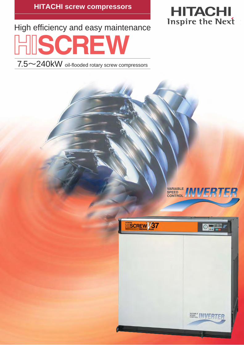
HITACHI screw compressors High efficiency and easy maintenance 7.5~240kW oil-flooded rotary screw compressors
Transcript of High efficiency and easy maintenance 7.5240kW · HITACHI screw compressors High efficiency and easy...
HITACHI screw compressors
High efficiency and easy maintenance
7.5~240kW oil-flooded rotary screw compressors
HITACHI screw compressors
High efficiency and easy maintenance
7.5~240kW oil-flooded rotary screw compressors
1 2
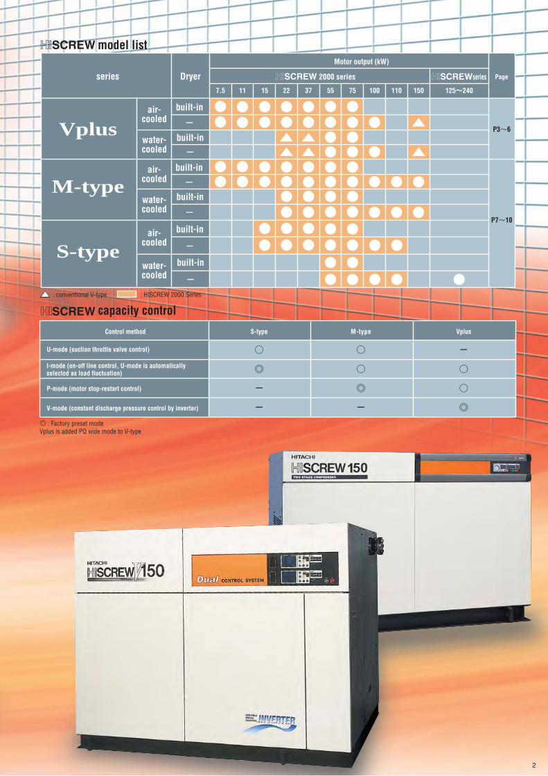
◎ : Factory preset modeVplus is added PQ wide mode to V-type
capacity control
Control method
U-mode (suction throttle valve control)
I-mode (on-off line control, U-mode is automatically selected as load fluctuation)
P-mode (motor stop-restart control)
V-mode (constant discharge pressure control by inverter)
S-type
○
◎
-
-
M-type
○
○
◎
-
Vplus
-
○
○
◎
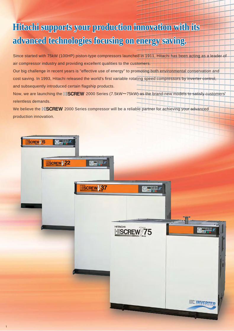
Since started with 75kW (100HP) piston-type compressors launched in 1911, Hitachi has been acting as a leader of
air compressor industry and providing excellent qualities to the customers.
Our big challenge in recent years is "effective use of energy" to promoting both environmental conservation and
cost saving. In 1993, Hitachi released the world's first variable rotating speed compressors by inverter control,
and subsequently introduced certain flagship products.
Now, we are launching the 2000 Series (7.5kW~75kW) as the brand-new models to satisfy customers'
relentless demands.
We believe the 2000 Series compressor will be a reliable partner for achieving your advanced
production innovation.
Hitachi supports your production innovation with its advanced technologies focusing on energy saving.Hitachi supports your production innovation with its advanced technologies focusing on energy saving.
P3~6
P7~10
series
Motor output (kW)
Dryer125~240
Page
model list
built-in
-
-
built-in
water-cooled
built-in
-
built-in
-air-
cooled
water-cooled
air-cooled
water-cooled
built-in
-
built-in
-
2000 series series
Vplus
M-type
S-type
air-cooled
11 157.5
: conventional V-type : HISCREW 2000 Series
22 37 15055 75 100 110
1 2
◎ : Factory preset modeVplus is added PQ wide mode to V-type
capacity control
Control method
U-mode (suction throttle valve control)
I-mode (on-off line control, U-mode is automatically selected as load fluctuation)
P-mode (motor stop-restart control)
V-mode (constant discharge pressure control by inverter)
S-type
○
◎
-
-
M-type
○
○
◎
-
Vplus
-
○
○
◎
Since started with 75kW (100HP) piston-type compressors launched in 1911, Hitachi has been acting as a leader of
air compressor industry and providing excellent qualities to the customers.
Our big challenge in recent years is "effective use of energy" to promoting both environmental conservation and
cost saving. In 1993, Hitachi released the world's first variable rotating speed compressors by inverter control,
and subsequently introduced certain flagship products.
Now, we are launching the 2000 Series (7.5kW~75kW) as the brand-new models to satisfy customers'
relentless demands.
We believe the 2000 Series compressor will be a reliable partner for achieving your advanced
production innovation.
Hitachi supports your production innovation with its advanced technologies focusing on energy saving.Hitachi supports your production innovation with its advanced technologies focusing on energy saving.
P3~6
P7~10
series
Motor output (kW)
Dryer125~240
Page
model list
built-in
-
-
built-in
water-cooled
built-in
-
built-in
-air-
cooled
water-cooled
air-cooled
water-cooled
built-in
-
built-in
-
2000 series series
Vplus
M-type
S-type
air-cooled
11 157.5
: conventional V-type : HISCREW 2000 Series
22 37 15055 75 100 110

New line-up with ''PQ wide mode'' ―― Vplus.
Vplus provides variable air capacity upon your requirement by inverter control.
0
10
20
30
40
50
60
70
80
90
100
20 40 60 80 10010 30 50 70 90
Air consumption (%)
Pow
er c
onsu
mpt
ion
(%) Approx.
38% power savings
HISCREW 2000 SeriesVplus
Typical compressors with suction throttle
Typical compressors with suction throttle and on/off line control
■Energy Saving (37kW model) ■Example of 37 kW annual power cost
Advantage :
(Power cost for 37-kW class, 6,000-hour annual operation)
By the best combination with Hitachi inverters, Vplus achieves considerable energy saving with easier maintenance.
With highly accurate discharge pressure control system, Vplus realises ± 0.01MPa as the maximum fluctuation of pressure. It can supply air with optimum pressure efficiently.
Power cost Maintenance cost Cost of amortizing body (7-year equal amortization)
10% 17%
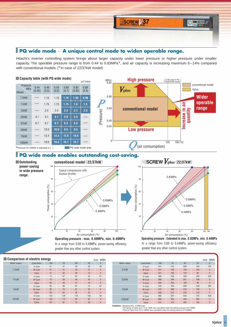
Hitachi's inverter controlling system brings about larger capacity under lower pressure or higher pressure under smaller capacity. The operable pressure range is from 0.44 to 0.83MPa*, and air capacity is increasing maximum 6-14% compared with conventional models. (*In case of 22/37kW model)
7.5kW
11kW
15kW
22kW
37kW
55kW
75kW
100kW
PressureMPa
(m3/min)
Model
4.1
6.7
0.96
1.5
2.0
1.03
1.6
2.1
3.3
5.5
8.5
10.8
16.7
1.15
1.75
2.4
4.1
6.7
10.0
13.4
19.0
1.15
1.75
2.4
4.1
6.7
10.0
13.4
19.0
1.15
1.75
2.4
3.8
6.3
9.5
12.6
18.1
0.44(0.45)
0.88(0.9)
0.83(0.85)
0.49(0.5)
0.59(0.6)
0.69(0.7)
■Capacity table (with PQ wide mode)
PQ wide mode area
0.83(MPa)
0.69
0 100 106(%)
0.59
0.49
0.44
In the case of the22kW/37kW model( )
Low pressure
High pressure
Incr
ease
in a
irqu
antit
y
conventional model
Vplus
■Outstanding power-savingin wide pressure range.
Operating pressure : Extended to max. 0.83MPa, min. 0.44MPaIn a range from 0.69 to 0.44MPa, power-saving efficiency greater than any other control system.
20
20
40
60
80
100
0 40 60 80 100
Air consumption (%)
0.83MPa
0.69MPa
0.59MPa
0.44MPa
3 4
●conventional model
[At 0.69 MPa]
●Vplus 37kW model
S-type/M-typeEnergy-saving effect
0.69
0.59
Vplusstable discharge pressure
Time
Pres
sure
( MPa
)
±0.01MPa
(22/37kW)
Stable discharge pressure.Reduction of power consumption.
PQ wide mode ― A unique control mode to widen operable range.
PQ wide mode enables outstanding cost-saving.
Vplus
conventional model(22/37kW)
Operating pressure : max. 0.69MPa, min. 0.49MPa
In a range from 0.69 to 0.49MPa, power-saving efficiency greater than any other control system.
20
20
40
60
80
100
0 40 60 80 100
Air consumption (%)
Pow
er c
onsu
mpt
ion
(%)
Pow
er c
onsu
mpt
ion
(%)
Typical compressors with Suction throttle
0.49MPa
0.59MPa
0.69MPa
Idealsystem 200MWh
123MWh200MWh
123MWh
73% 73%
1.8m3/min
2.4m3/min
3.8m3/min
6.3m3/min
2.0m3/min
2.4m3/min
3.8m3/min
6.3m3/min
Unit : MWh■Comparison of electric energy Unit : MWh
■Vplus achieves cost saving by ideal air capacity control.
1,200rpm
1,400rpm
2,250rpm
3,700rpm
11kW
15kW
22kW
37kW
106
conventional model
(Pre
ssur
e)
(air consumption)
Wider operable range
The annual power cost for a compressor is equivalent to the approximate cost of installing one compressor.
Conditions : Operating time : 6,000hr/year The figures of Vplus from 7.5 to 15kW were calculated under the setting pressure of 0.73MPa. Those of Vplus from 22 to 100kW were calculated under the setting pressure of 0.59MPa.
Note : U-type is commonly used suction throttle valve control.
*Pressure for 100kW is indicated in ( ).
(Average air consumption 50% Operating time : 6000h/year)
38%Load factorMotor output 70
47
41
35
67
59
49
86
76
63
129
115
97
20
39
21
13
55
30
19
72
35
25
103
62
39
100
51
51
47
73
73
68
95
95
89
143
143
131
50
43
33
26
62
48
37
81
61
48
119
94
73
0
35
0
0
51
0
0
67
0
0
93
0
0
U-typeM-type
Vplus
U-typeM-type
U-typeM-type
U-type
M-type
Vplus
Vplus
Vplus
7.5kW
11kW
15kW
22kW
Load factorMotor output
U-typeM-type
Vplus
U-typeM-type
U-typeM-type
V-type
Vplus
U-typeM-typeVplus
37kW
55kW
75kW
100kW
100
241
241
221
366
366
335
476
476
436
660
660
615
70
216
195
162
328
294
245
424
380
313
591
534
472
20
164
104
65
260
168
94
339
193
124
475
295
182
50
200
158
123
300
247
185
390
310
234
545
443
353
0
157
0
0
235
0
0
304
0
0
429
0
0
New line-up with ''PQ wide mode'' ―― Vplus.
Vplus provides variable air capacity upon your requirement by inverter control.
0
10
20
30
40
50
60
70
80
90
100
20 40 60 80 10010 30 50 70 90
Air consumption (%)
Pow
er c
onsu
mpt
ion
(%) Approx.
38% power savings
HISCREW 2000 SeriesVplus
Typical compressors with suction throttle
Typical compressors with suction throttle and on/off line control
■Energy Saving (37kW model) ■Example of 37 kW annual power cost
Advantage :
(Power cost for 37-kW class, 6,000-hour annual operation)
By the best combination with Hitachi inverters, Vplus achieves considerable energy saving with easier maintenance.
With highly accurate discharge pressure control system, Vplus realises ± 0.01MPa as the maximum fluctuation of pressure. It can supply air with optimum pressure efficiently.
Power cost Maintenance cost Cost of amortizing body (7-year equal amortization)
10% 17%
Hitachi's inverter controlling system brings about larger capacity under lower pressure or higher pressure under smaller capacity. The operable pressure range is from 0.44 to 0.83MPa*, and air capacity is increasing maximum 6-14% compared with conventional models. (*In case of 22/37kW model)
7.5kW
11kW
15kW
22kW
37kW
55kW
75kW
100kW
PressureMPa
(m3/min)
Model
4.1
6.7
0.96
1.5
2.0
1.03
1.6
2.1
3.3
5.5
8.5
10.8
16.7
1.15
1.75
2.4
4.1
6.7
10.0
13.4
19.0
1.15
1.75
2.4
4.1
6.7
10.0
13.4
19.0
1.15
1.75
2.4
3.8
6.3
9.5
12.6
18.1
0.44(0.45)
0.88(0.9)
0.83(0.85)
0.49(0.5)
0.59(0.6)
0.69(0.7)
■Capacity table (with PQ wide mode)
PQ wide mode area
0.83(MPa)
0.69
0 100 106(%)
0.59
0.49
0.44
In the case of the22kW/37kW model( )
Low pressure
High pressure
Incr
ease
in a
irqu
antit
y
conventional model
Vplus
■Outstanding power-savingin wide pressure range.
Operating pressure : Extended to max. 0.83MPa, min. 0.44MPaIn a range from 0.69 to 0.44MPa, power-saving efficiency greater than any other control system.
20
20
40
60
80
100
0 40 60 80 100
Air consumption (%)
0.83MPa
0.69MPa
0.59MPa
0.44MPa
3 4
●conventional model
[At 0.69 MPa]
●Vplus 37kW model
S-type/M-typeEnergy-saving effect
0.69
0.59
Vplusstable discharge pressure
Time
Pres
sure
( MPa
)
±0.01MPa
(22/37kW)
Stable discharge pressure.Reduction of power consumption.
PQ wide mode ― A unique control mode to widen operable range.
PQ wide mode enables outstanding cost-saving.
Vplus
conventional model(22/37kW)
Operating pressure : max. 0.69MPa, min. 0.49MPa
In a range from 0.69 to 0.49MPa, power-saving efficiency greater than any other control system.
20
20
40
60
80
100
0 40 60 80 100
Air consumption (%)
Pow
er c
onsu
mpt
ion
(%)
Pow
er c
onsu
mpt
ion
(%)
Typical compressors with Suction throttle
0.49MPa
0.59MPa
0.69MPa
Idealsystem 200MWh
123MWh200MWh
123MWh
73% 73%
1.8m3/min
2.4m3/min
3.8m3/min
6.3m3/min
2.0m3/min
2.4m3/min
3.8m3/min
6.3m3/min
Unit : MWh■Comparison of electric energy Unit : MWh
■Vplus achieves cost saving by ideal air capacity control.
1,200rpm
1,400rpm
2,250rpm
3,700rpm
11kW
15kW
22kW
37kW
106
conventional model
(Pre
ssur
e)
(air consumption)
Wider operable range
The annual power cost for a compressor is equivalent to the approximate cost of installing one compressor.
Conditions : Operating time : 6,000hr/year The figures of Vplus from 7.5 to 15kW were calculated under the setting pressure of 0.73MPa. Those of Vplus from 22 to 100kW were calculated under the setting pressure of 0.59MPa.
Note : U-type is commonly used suction throttle valve control.
*Pressure for 100kW is indicated in ( ).
(Average air consumption 50% Operating time : 6000h/year)
38%Load factorMotor output 70
47
41
35
67
59
49
86
76
63
129
115
97
20
39
21
13
55
30
19
72
35
25
103
62
39
100
51
51
47
73
73
68
95
95
89
143
143
131
50
43
33
26
62
48
37
81
61
48
119
94
73
0
35
0
0
51
0
0
67
0
0
93
0
0
U-typeM-type
Vplus
U-typeM-type
U-typeM-type
U-type
M-type
Vplus
Vplus
Vplus
7.5kW
11kW
15kW
22kW
Load factorMotor output
U-typeM-type
Vplus
U-typeM-type
U-typeM-type
V-type
Vplus
U-typeM-typeVplus
37kW
55kW
75kW
100kW
100
241
241
221
366
366
335
476
476
436
660
660
615
70
216
195
162
328
294
245
424
380
313
591
534
472
20
164
104
65
260
168
94
339
193
124
475
295
182
50
200
158
123
300
247
185
390
310
234
545
443
353
0
157
0
0
235
0
0
304
0
0
429
0
0
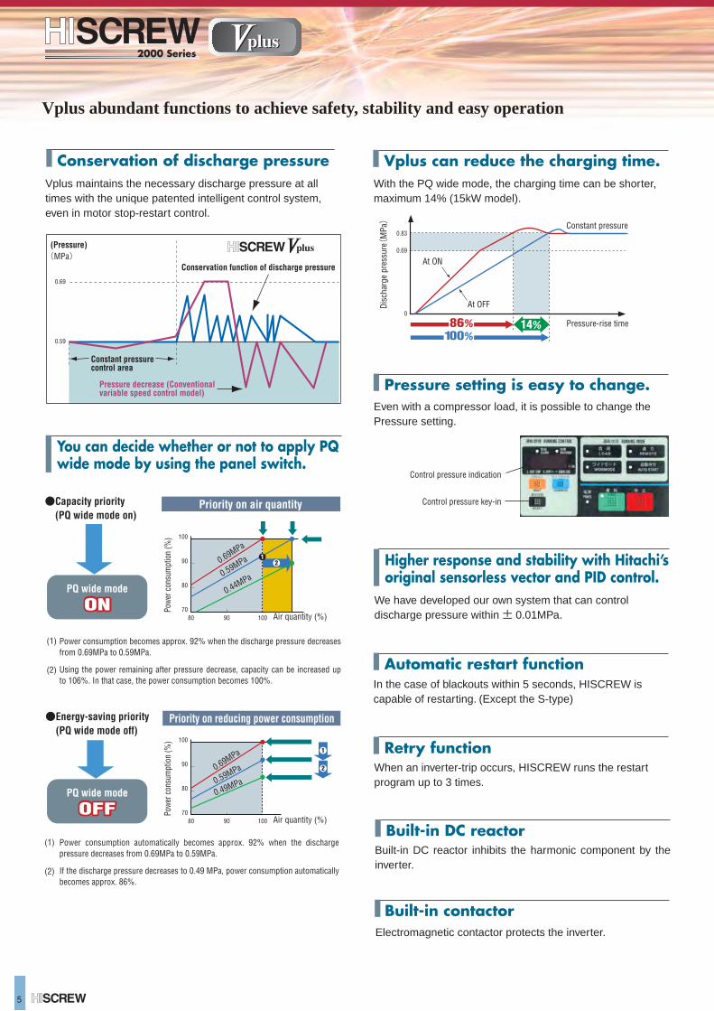
Vplus abundant functions to achieve safety, stability and easy operation
Conservation of discharge pressureVplus maintains the necessary discharge pressure at all times with the unique patented intelligent control system, even in motor stop-restart control.
Built-in DC reactor inhibits the harmonic component by the inverter.
5
0.69
(MPa)
0.59
(Pressure)
Pressure decrease (Conventional variable speed control model)
Constant pressure control area
Conservation function of discharge pressure
Even with a compressor load, it is possible to change the Pressure setting.
Control pressure indication
Control pressure key-in
We have developed our own system that can control discharge pressure within ± 0.01MPa.
When an inverter-trip occurs, HISCREW runs the restart program up to 3 times.
In the case of blackouts within 5 seconds, HISCREW is capable of restarting. (Except the S-type)
Electromagnetic contactor protects the inverter.
Power consumption automatically becomes approx. 92% when the discharge pressure decreases from 0.69MPa to 0.59MPa.
If the discharge pressure decreases to 0.49 MPa, power consumption automatically becomes approx. 86%.
(1)
(2)
●Energy-saving priority (PQ wide mode off)
9080 100
80
70
90
100
Air quantity (%)
1
2
0.49MPa0.59MPa0.69MPa
Priority on reducing power consumption
Power consumption becomes approx. 92% when the discharge pressure decreases from 0.69MPa to 0.59MPa.
Using the power remaining after pressure decrease, capacity can be increased up to 106%. In that case, the power consumption becomes 100%.
(1)
(2)
Air quantity (%)9080 100
80
70
90
100
0.44MPa0.59MPa0.69MPa1
2
Powe
r con
sum
ptio
n (%
)Po
wer c
onsu
mpt
ion
(%)
●Capacity priority (PQ wide mode on)
PQ wide mode
ON
Priority on air quantity
Higher response and stability with Hitachi’s original sensorless vector and PID control.
With the PQ wide mode, the charging time can be shorter, maximum 14% (15kW model).
Vplus can reduce the charging time.
Pressure setting is easy to change.
Automatic restart function
Retry function
Built-in DC reactor
Built-in contactor
You can decide whether or not to apply PQ wide mode by using the panel switch.
ON
PQ wide mode
OFFOFF
0
0.69
0.83
Dis
char
ge p
ress
ure
(MPa
)
Pressure-rise time
Constant pressure
At ON
At OFF
86% 14%100%
Vplus
6
kW
MPa
m3/min
MPa
m3/min
MPa
MPa
―
˚C
―
―
L
˚C
kW
―
B
mm
55
3722
( )Dryer equipped.
kg
dB[A]
0.69 [0.83]
32 or lower
45 65 100 100 125
―
―
―
1,200×890×1,260 1,400×970×1,400
570(620) 940(1,010) 1,540(1,710)
57 60 65 66
1 1 1/2 2 [Flange]
OSP-37VW(R)ⅠOSP-22VW(R)Ⅰ OSP-55VW(R)Ⅰ OSP-75VWL(R)Ⅰ OSP-100VWLⅠ
75 100
0.7
3.8 [3.3] 6.3 [5.5] 9.5 12.6 18.1
0.59 0.83
10 8.5
0.59 0.83
13.4 10.8
0.6 0.85
19.0 16.7
0.49~0.83
0.59~0.83
˚C
L/min
1.1 2.2 3.0
HFC-R407C/Capillary tube
1 1/2
1,850×1,100×1,450 1,850×1,150×1,470
2,300
69
2 1/2[Flange]
2,050×1,365×1,875
1,100(1,220)
kW
MPa
m3/min
MPa
m3/min
MPa
MPa
―
˚C
―
L
˚C
kW
―
B
mm
Ambient pressure / 0~40˚C (5~40˚C)
Suction temperature + 15 or lower
Ambient pressure / 0~40˚C (5~40˚C)
Cooling water temperature + 13˚C or lower
4-pole TEFC motor V-belt drive. Inverter control
4-pole TEFC motor V-belt drive. Inverter control
2-pole TEFC motor gear drive
2-pole TEFC motor gear drive
75
12.6
100
0.7
18.1
0.5~0.85
0.6~0.85
55
9.5
37
6.3
22
3.8
15
2.1
11
1.6
0.83
7.5
1.03
OSP-7.5VA(R)Ⅲ OSP-11VA(R)Ⅲ OSP-15VA(R)Ⅲ OSP-22V5A(R)ⅡOSP-22V6A(R)Ⅱ
OSP-37V5A(R)ⅡOSP-37V6A(R)Ⅱ
OSP-55V5A(R)ⅠOSP-55V6A(R)Ⅰ
OSP-75V5AL(R)ⅠOSP-75V6AL(R)Ⅰ
OSP-100V5ALⅠOSP-100V6ALⅠ
kg
dB[A]
0.69
1.15
0.69
0.88
0.96
0.69
1.75
0.88
1.5
0.69
2.4
0.59
4.1
0.88
2.0
0.83
3.3
0.59
6.7
0.83
5.5
0.59
10
0.83
8.5
0.59
13.4
0.83
10.8
0.6
19.0
0.85
16.7
0.49~0.88 0.44~0.83 0.49~0.83
0.69~0.88 0.59~0.83
10 Under pressure
10 Under pressure
0.3 0.5 1.1 2.2 3.0
―
―
―
2 1/2[Flange]
2,050×1,365×1,875
2,400
72
840×710×1,075 930×770×1,200 1,200×890×1,260 1,400×970×1,400 1,850×1,100×1,450 1,850×1,150×1,470
285(310) 335(365) 350(380) 570(620) 820(890) 1,070(1,190) 1,500(1,670)
53 55 56 57 60 66 69
Rc1 Rc3/4 1 1 1/2 1 1/2 2 [Flange]
HFC-R407C/Capillary tube
0.49~0.69 [0.49~0.69 ]
( )Dryer equipped.
0.69
―
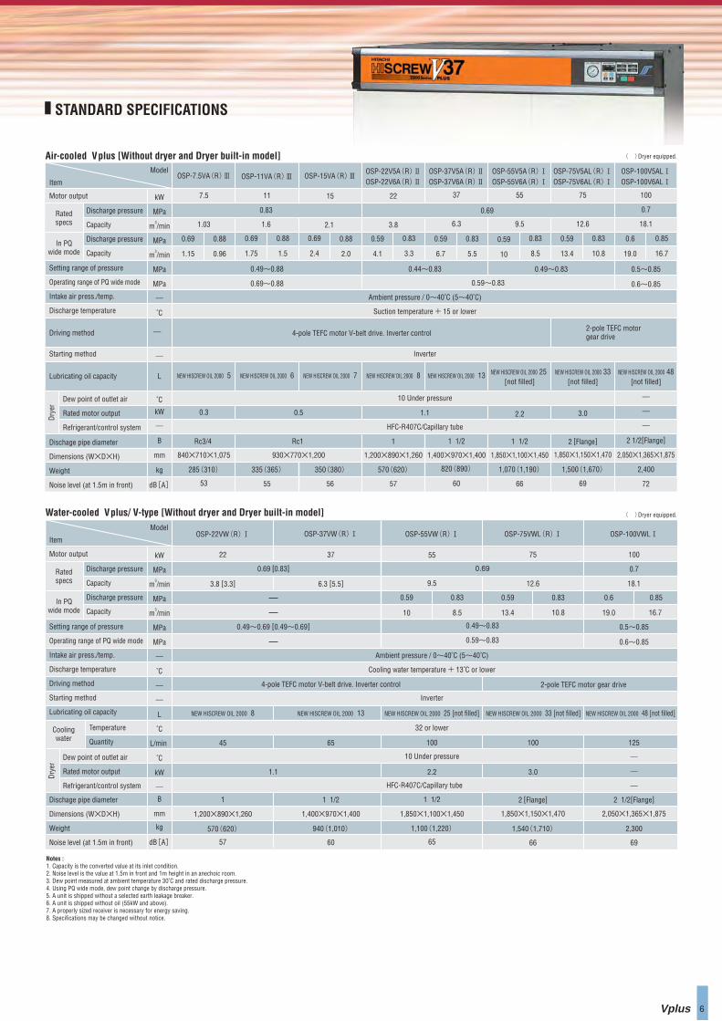
Notes :1. Capacity is the converted value at its inlet condition.2. Noise level is the value at 1.5m in front and 1m height in an anechoic room.3. Dew point measured at ambient temperature 30˚C and rated discharge pressure.4. Using PQ wide mode, dew point change by discharge pressure. 5. A unit is shipped without a selected earth leakage breaker.6. A unit is shipped without oil (55kW and above).7. A properly sized receiver is necessary for energy saving.8. Specifications may be changed without notice.
STANDARD SPECIFICATIONS
Air-cooled Vplus [Without dryer and Dryer built-in model]
Water-cooled Vplus/ V-type [Without dryer and Dryer built-in model]
Motor output
Motor output
Item
Model
Item
Model
Ratedspecs
In PQwide mode
Discharge pressure
Capacity
Discharge pressure
Capacity
Ratedspecs
In PQwide mode
Discharge pressure
Capacity
Discharge pressure
Capacity
Dew point of outlet air
Rated motor output
Refrigerant/control system
Setting range of pressure
Operating range of PQ wide mode
Intake air press./temp.
Discharge temperature
Driving method
Starting method
Lubricating oil capacity
Setting range of pressure
Operating range of PQ wide mode
Intake air press./temp.
Discharge temperature
Driving method
Starting method
Lubricating oil capacity
Dischage pipe diameter
Dimensions (W×D×H)
Weight
Noise level (at 1.5m in front)
Dry
er
Dew point of outlet air
Rated motor output
Refrigerant/control system
Temperature
Quantity
Dry
er
Coolingwater
Dischage pipe diameter
Dimensions (W×D×H)
Weight
Noise level (at 1.5m in front)
NEW HISCREW OIL 2000 5
NEW HISCREW OIL 2000 8 NEW HISCREW OIL 2000 13 NEW HISCREW OIL 2000 25 [not filled] NEW HISCREW OIL 2000 33 [not filled] NEW HISCREW OIL 2000 48 [not filled]
NEW HISCREW OIL 2000 6 NEW HISCREW OIL 2000 7 NEW HISCREW OIL 2000 8 NEW HISCREW OIL 2000 13 NEW HISCREW OIL 2000 25 [not filled]
NEW HISCREW OIL 2000 33[not filled]
NEW HISCREW OIL 2000 48[not filled]
Inverter
Inverter
0.5~0.85
0.6~0.85
Vplus
6
kW
MPa
m3/min
MPa
m3/min
MPa
MPa
―
˚C
―
―
L
˚C
kW
―
B
mm
55
3722
( )Dryer equipped.
kg
dB[A]
0.69 [0.83]
32 or lower
45 65 100 100 125
―
―
―
1,200×890×1,260 1,400×970×1,400
570(620) 940(1,010) 1,540(1,710)
57 60 65 66
1 1 1/2 2 [Flange]
OSP-37VW(R)ⅠOSP-22VW(R)Ⅰ OSP-55VW(R)Ⅰ OSP-75VWL(R)Ⅰ OSP-100VWLⅠ
75 100
0.7
3.8 [3.3] 6.3 [5.5] 9.5 12.6 18.1
0.59 0.83
10 8.5
0.59 0.83
13.4 10.8
0.6 0.85
19.0 16.7
0.49~0.83
0.59~0.83
˚C
L/min
1.1 2.2 3.0
HFC-R407C/Capillary tube
1 1/2
1,850×1,100×1,450 1,850×1,150×1,470
2,300
69
2 1/2[Flange]
2,050×1,365×1,875
1,100(1,220)
kW
MPa
m3/min
MPa
m3/min
MPa
MPa
―
˚C
―
L
˚C
kW
―
B
mm
Ambient pressure / 0~40˚C (5~40˚C)
Suction temperature + 15 or lower
Ambient pressure / 0~40˚C (5~40˚C)
Cooling water temperature + 13˚C or lower
4-pole TEFC motor V-belt drive. Inverter control
4-pole TEFC motor V-belt drive. Inverter control
2-pole TEFC motor gear drive
2-pole TEFC motor gear drive
75
12.6
100
0.7
18.1
0.5~0.85
0.6~0.85
55
9.5
37
6.3
22
3.8
15
2.1
11
1.6
0.83
7.5
1.03
OSP-7.5VA(R)Ⅲ OSP-11VA(R)Ⅲ OSP-15VA(R)Ⅲ OSP-22V5A(R)ⅡOSP-22V6A(R)Ⅱ
OSP-37V5A(R)ⅡOSP-37V6A(R)Ⅱ
OSP-55V5A(R)ⅠOSP-55V6A(R)Ⅰ
OSP-75V5AL(R)ⅠOSP-75V6AL(R)Ⅰ
OSP-100V5ALⅠOSP-100V6ALⅠ
kg
dB[A]
0.69
1.15
0.69
0.88
0.96
0.69
1.75
0.88
1.5
0.69
2.4
0.59
4.1
0.88
2.0
0.83
3.3
0.59
6.7
0.83
5.5
0.59
10
0.83
8.5
0.59
13.4
0.83
10.8
0.6
19.0
0.85
16.7
0.49~0.88 0.44~0.83 0.49~0.83
0.69~0.88 0.59~0.83
10 Under pressure
10 Under pressure
0.3 0.5 1.1 2.2 3.0
―
―
―
2 1/2[Flange]
2,050×1,365×1,875
2,400
72
840×710×1,075 930×770×1,200 1,200×890×1,260 1,400×970×1,400 1,850×1,100×1,450 1,850×1,150×1,470
285(310) 335(365) 350(380) 570(620) 820(890) 1,070(1,190) 1,500(1,670)
53 55 56 57 60 66 69
Rc1 Rc3/4 1 1 1/2 1 1/2 2 [Flange]
HFC-R407C/Capillary tube
0.49~0.69 [0.49~0.69 ]
( )Dryer equipped.
0.69
―
Notes :1. Capacity is the converted value at its inlet condition.2. Noise level is the value at 1.5m in front and 1m height in an anechoic room.3. Dew point measured at ambient temperature 30˚C and rated discharge pressure.4. Using PQ wide mode, dew point change by discharge pressure. 5. A unit is shipped without a selected earth leakage breaker.6. A unit is shipped without oil (55kW and above).7. A properly sized receiver is necessary for energy saving.8. Specifications may be changed without notice.
STANDARD SPECIFICATIONS
Air-cooled Vplus [Without dryer and Dryer built-in model]
Water-cooled Vplus/ V-type [Without dryer and Dryer built-in model]
Motor output
Motor output
Item
Model
Item
Model
Ratedspecs
In PQwide mode
Discharge pressure
Capacity
Discharge pressure
Capacity
Ratedspecs
In PQwide mode
Discharge pressure
Capacity
Discharge pressure
Capacity
Dew point of outlet air
Rated motor output
Refrigerant/control system
Setting range of pressure
Operating range of PQ wide mode
Intake air press./temp.
Discharge temperature
Driving method
Starting method
Lubricating oil capacity
Setting range of pressure
Operating range of PQ wide mode
Intake air press./temp.
Discharge temperature
Driving method
Starting method
Lubricating oil capacity
Dischage pipe diameter
Dimensions (W×D×H)
Weight
Noise level (at 1.5m in front)
Dry
er
Dew point of outlet air
Rated motor output
Refrigerant/control system
Temperature
Quantity
Dry
er
Coolingwater
Dischage pipe diameter
Dimensions (W×D×H)
Weight
Noise level (at 1.5m in front)
NEW HISCREW OIL 2000 5
NEW HISCREW OIL 2000 8 NEW HISCREW OIL 2000 13 NEW HISCREW OIL 2000 25 [not filled] NEW HISCREW OIL 2000 33 [not filled] NEW HISCREW OIL 2000 48 [not filled]
NEW HISCREW OIL 2000 6 NEW HISCREW OIL 2000 7 NEW HISCREW OIL 2000 8 NEW HISCREW OIL 2000 13 NEW HISCREW OIL 2000 25 [not filled]
NEW HISCREW OIL 2000 33[not filled]
NEW HISCREW OIL 2000 48[not filled]
Inverter
Inverter
0.5~0.85
0.6~0.85
7
High performance realized by newly developed rotor
Line
pre
ssur
e
↓
Time→
High-limit pressure (Unload start pressure)
Low-limit pressure (Load reset pressure)
Load Unload
High-limit pressure lowered automatically
Energy-saving effect: Approx. 3% max.
0
10
20
30
40
50
60
70
80
90
100
20 40 60 80 10010 30 50 70 90
Air consumption (%)
Pow
er c
onsu
mpt
ion
(%)
typical compressors with suction throttle and on-off line control
typical compressors with suction throttle
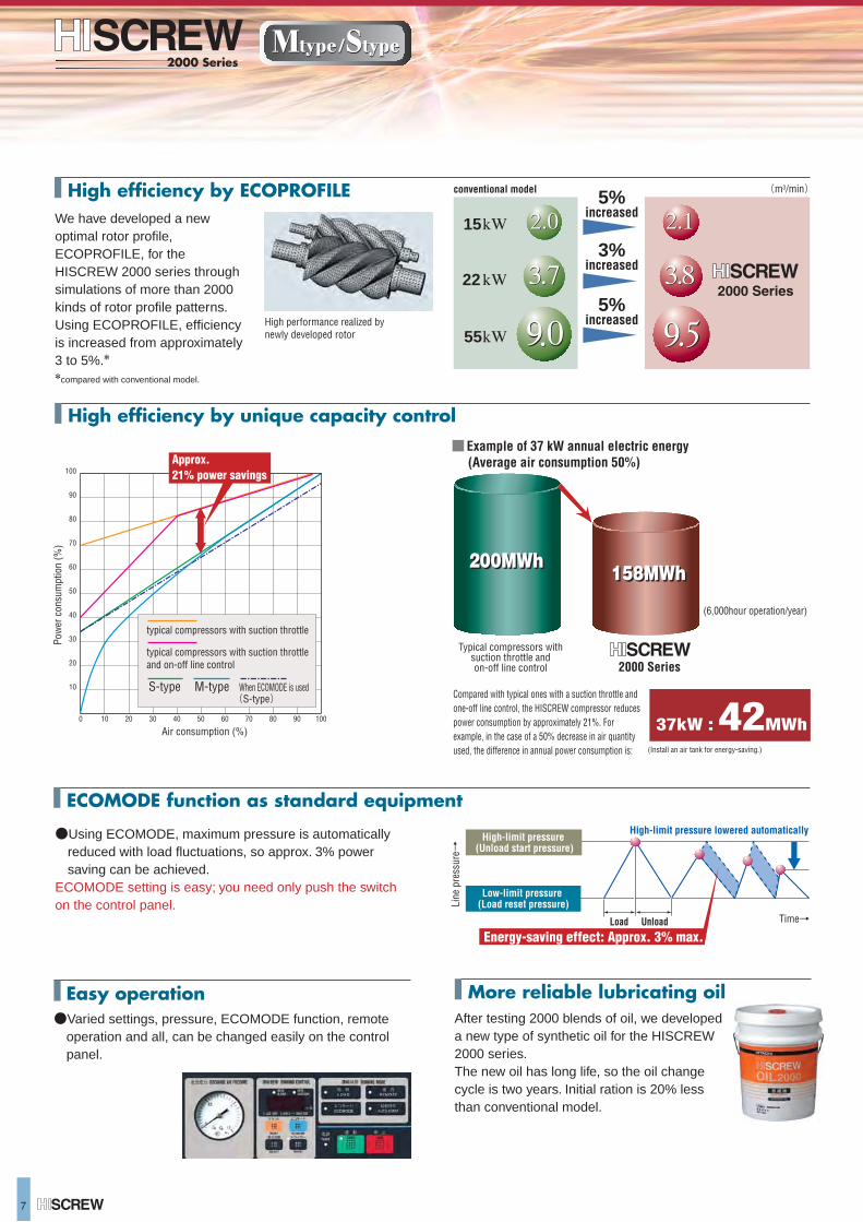
After testing 2000 blends of oil, we developed a new type of synthetic oil for the HISCREW 2000 series.The new oil has long life, so the oil change cycle is two years. Initial ration is 20% less than conventional model.
We have developed a new optimal rotor profile, ECOPROFILE, for the HISCREW 2000 series through simulations of more than 2000 kinds of rotor profile patterns. Using ECOPROFILE, efficiency is increased from approximately 3 to 5%.**compared with conventional model.
●Using ECOMODE, maximum pressure is automatically reduced with load fluctuations, so approx. 3% power saving can be achieved.
ECOMODE setting is easy; you need only push the switch on the control panel.
High efficiency by unique capacity control
(m3/min) conventional model 5%increased
5%increased
3%increased
Approx. 21% power savings
Easy operation●Varied settings, pressure, ECOMODE function, remote
operation and all, can be changed easily on the control panel.
More reliable lubricating oil
High efficiency by ECOPROFILE
(6,000hour operation/year)
■Example of 37 kW annual electric energy (Average air consumption 50%)
(Install an air tank for energy-saving.)
Typical compressors withsuction throttle andon-off line control 2000 Series
200MWh
Compared with typical ones with a suction throttle and one-off line control, the HISCREW compressor reduces power consumption by approximately 21%. For example, in the case of a 50% decrease in air quantity used, the difference in annual power consumption is:
37kW : 42MWh
158MWh
15
22
55
ECOMODE function as standard equipment
S-type M-type(S-type)
When ECOMODE is used
200MWh158MWh
7
High performance realized by newly developed rotor
Line
pre
ssur
e
↓
Time→
High-limit pressure (Unload start pressure)
Low-limit pressure (Load reset pressure)
Load Unload
High-limit pressure lowered automatically
Energy-saving effect: Approx. 3% max.
0
10
20
30
40
50
60
70
80
90
100
20 40 60 80 10010 30 50 70 90
Air consumption (%)
Pow
er c
onsu
mpt
ion
(%)
typical compressors with suction throttle and on-off line control
typical compressors with suction throttle
After testing 2000 blends of oil, we developed a new type of synthetic oil for the HISCREW 2000 series.The new oil has long life, so the oil change cycle is two years. Initial ration is 20% less than conventional model.
We have developed a new optimal rotor profile, ECOPROFILE, for the HISCREW 2000 series through simulations of more than 2000 kinds of rotor profile patterns. Using ECOPROFILE, efficiency is increased from approximately 3 to 5%.**compared with conventional model.
●Using ECOMODE, maximum pressure is automatically reduced with load fluctuations, so approx. 3% power saving can be achieved.
ECOMODE setting is easy; you need only push the switch on the control panel.
High efficiency by unique capacity control
(m3/min) conventional model 5%increased
5%increased
3%increased
Approx. 21% power savings
Easy operation●Varied settings, pressure, ECOMODE function, remote
operation and all, can be changed easily on the control panel.
More reliable lubricating oil
High efficiency by ECOPROFILE
(6,000hour operation/year)
■Example of 37 kW annual electric energy (Average air consumption 50%)
(Install an air tank for energy-saving.)
Typical compressors withsuction throttle andon-off line control 2000 Series
200MWh
Compared with typical ones with a suction throttle and one-off line control, the HISCREW compressor reduces power consumption by approximately 21%. For example, in the case of a 50% decrease in air quantity used, the difference in annual power consumption is:
37kW : 42MWh
158MWh
15
22
55
ECOMODE function as standard equipment
S-type M-type(S-type)
When ECOMODE is used
200MWh158MWh
Mtype / Stype 8
Hitachi HISCREW 2000 series (Vplus, M-type and S-type) share
a common design and parts. Our original way of systematic
upgrade, in which Vplus plays a central role, have a lead as a
whole.
Conventional model of
75kW
V-M combination system
Hitachi’s V-M combination system would be the most
appropriate as a system of 2 to 3 compressors because of
our original common design.
V-M combination system brings certain advantages
described below.
●
●
Can save energy by varied combination●
M-type 37kWVplus 37kW
V-type
Initi
al in
vest
men
t (%
) 100
50
075kW Vplus
25%
37kW VMcombination
M-type
Vplus
Vplus
Vplus M-type
Powe
r con
sum
ption
ratio
(%)
0200100
200
100
Used air ratio (%)
Suction throttle valve control
Single-V, Multi-V system
Advantages
※Compared amount without dryer models.
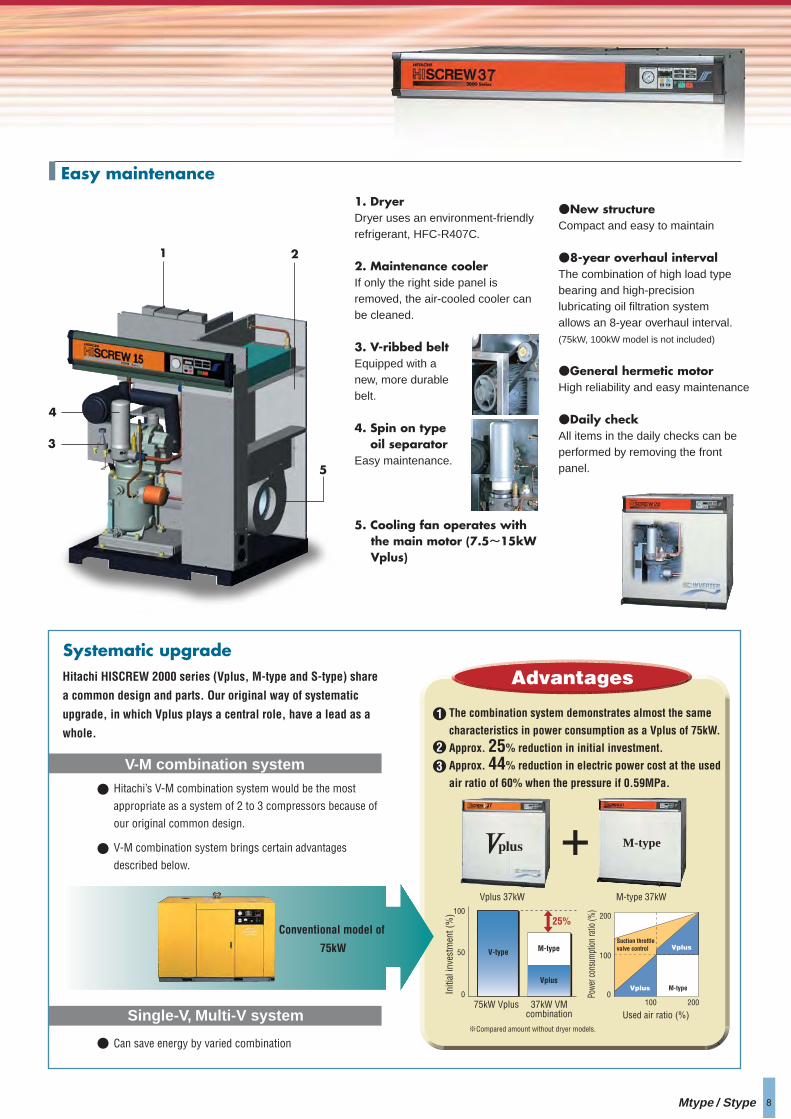
1. DryerDryer uses an environment-friendly refrigerant, HFC-R407C.
2. Maintenance coolerIf only the right side panel is removed, the air-cooled cooler can be cleaned.
3. V-ribbed beltEquipped with a new, more durable belt.
4. Spin on type oil separatorEasy maintenance.
5. Cooling fan operates with the main motor (7.5~15kW Vplus)
●New structureCompact and easy to maintain
●8-year overhaul intervalThe combination of high load type bearing and high-precision lubricating oil filtration system allows an 8-year overhaul interval.(75kW, 100kW model is not included)
●General hermetic motorHigh reliability and easy maintenance
●Daily checkAll items in the daily checks can be performed by removing the front panel.
1 2
3
4
5
Easy maintenance
Systematic upgrade
The combination system demonstrates almost the same
characteristics in power consumption as a Vplus of 75kW.
Approx. 25% reduction in initial investment.
Approx. 44% reduction in electric power cost at the used
air ratio of 60% when the pressure if 0.59MPa.
1
2
3
M-type
Mtype / Stype 8
Hitachi HISCREW 2000 series (Vplus, M-type and S-type) share
a common design and parts. Our original way of systematic
upgrade, in which Vplus plays a central role, have a lead as a
whole.
Conventional model of
75kW
V-M combination system
Hitachi’s V-M combination system would be the most
appropriate as a system of 2 to 3 compressors because of
our original common design.
V-M combination system brings certain advantages
described below.
●
●
Can save energy by varied combination●
M-type 37kWVplus 37kW
V-type
Initi
al in
vest
men
t (%
) 100
50
075kW Vplus
25%
37kW VMcombination
M-type
Vplus
Vplus
Vplus M-type
Powe
r con
sum
ption
ratio
(%)
0200100
200
100
Used air ratio (%)
Suction throttle valve control
Single-V, Multi-V system
Advantages
※Compared amount without dryer models.
1. DryerDryer uses an environment-friendly refrigerant, HFC-R407C.
2. Maintenance coolerIf only the right side panel is removed, the air-cooled cooler can be cleaned.
3. V-ribbed beltEquipped with a new, more durable belt.
4. Spin on type oil separatorEasy maintenance.
5. Cooling fan operates with the main motor (7.5~15kW Vplus)
●New structureCompact and easy to maintain
●8-year overhaul intervalThe combination of high load type bearing and high-precision lubricating oil filtration system allows an 8-year overhaul interval.(75kW, 100kW model is not included)
●General hermetic motorHigh reliability and easy maintenance
●Daily checkAll items in the daily checks can be performed by removing the front panel.
1 2
3
4
5
Easy maintenance
Systematic upgrade
The combination system demonstrates almost the same
characteristics in power consumption as a Vplus of 75kW.
Approx. 25% reduction in initial investment.
Approx. 44% reduction in electric power cost at the used
air ratio of 60% when the pressure if 0.59MPa.
1
2
3
M-type
Optional Specifications
9
Air tankoperation/stopload/unload
wiring
Note : 1. HG Version is applicable only to 22 - 75kW, for both Vplus and M-type of HISCREW2000 series. 2. Both of two compressors must be HG Version to use the alternating or follow-up function.3. In order to use the alternating or follow-up function, separate wiring works are necessary. (Prepare the connecting cable at the expense of customer since it does not come with this equipment.)4. In order to use the communication function, separate remote supervisory system (COSMOS) and wiring works are necessary. (Prepare the communication cable at the expense of customer since it does not come with this equipment.)
Energy saving operation, scheduled operation, alternating or follow-up operation (in parallel or interval change-over), communication function, maintenance time notification, storing operational and load data, timely switching of pressure setup, switching of external pressure setup, etc.
Total operation time, discharge pressure, load factor, the number of loading, electric current, total loading time, detailed failure history, etc.Only Vplus displays motor output and frequency, and inverter failure history.
Primary functions
Contents displayed on the monitor
ECOSEP maintains the oil concentration level in the drain at 5 mg/L or less.
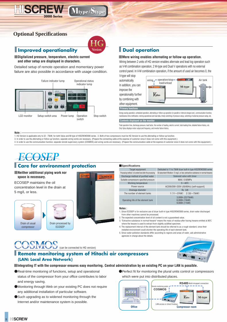
Wiring between 2 units of HG version enables alternate and lead log operation such as V-M combination operation, 2 M-type and Dual V operations with no external control panel. In V-M combination operation, if the amount of used air becomes 0, the V-type will stop automatically.In addition, you can improve the operationality further by combining with other equipment.
LCD monitor Setup switch area Operation switch
Stop switch
Failure indicator lump Operational status indicator lump
Power lump
Compressor roomOffice
Multi-dropped connection
LAN access or direct hookup
RS485Remote monitoring system
COSMOS
Drain of usualcompressor
Drain processed byECOSEP
Notes :1. Since ECOSEP is for exclusive use of dryer built-in type HISCREW2000 series, drain water discharged
from other machines cannot be processed.2. The expected concentration level of oil content is not a guaranteed value.3. ''Extractive substance in normal-hexane" means the mass of residue after having hexane emitted at 80℃
where the hexane is used to extract from slightly acidified specimen.4. The replacement interval of the element tank should be referred to as a rough standard, since their
installed environment could shorten the operating life of each element tank.5. Since water-pollution standards differ according to regions and areas of water, ask administrative
agencies in charge about the details.
Target equipmentProcessing method / oil content level after the processingDischarge method of purified water
Suitable compressors specified pressureWorking temperature
Power source
The number of element tanksDrainage diameter
Operating life of the element tank
Dedicated to 11 to 75kW dryer built-in type HISCREW2000 seriesOil absorbent filtration / 5 mg/L or less (extractive substance in normal-hexane)
Solenoid valve with timer
AC200/200・220V (50/60Hz) [self-support]Rc 3/8
1(11~37kW) 2(55~75kW)
MAX. 0.92MPa5~40℃
3,000h (22/75kW)6,000h (15kW)9,000h (11kW)
●Real-time monitoring of functions, setup and operational
status of the compressor from your office contributes to labor
and energy saving.
●Monitoring through Web on your existing PC does not require
any additional installation of particular software.
●Such upgrading as to widened monitoring through the
Internet and/or maintenance system is possible.
●Perfect fit for monitoring the plural units control or compressors
which were put into distributed places.
■Integrating IT with the compressor ensures easy monitoring. Central administration by an existing PC on your LAN is possible.
(can be connected to HG version)
■Specifications
■Neither additional piping work nor space is necessary.
■Mere wiring enables alternating or follow-up operation.
Dual operation
Care for environment protection
Detailed setup of remote operation and momentary power failure are also possible in accordance with usage condition.
■Digitalized pressure, temperature, electric current and other setup are displayed in characters.
Improved operationality
Remote monitoring system of Hitachi air compressors (LAN: Local Area Network)
M-type
M-type
Optional Specifications
9
Air tankoperation/stopload/unload
wiring
Note : 1. HG Version is applicable only to 22 - 75kW, for both Vplus and M-type of HISCREW2000 series. 2. Both of two compressors must be HG Version to use the alternating or follow-up function.3. In order to use the alternating or follow-up function, separate wiring works are necessary. (Prepare the connecting cable at the expense of customer since it does not come with this equipment.)4. In order to use the communication function, separate remote supervisory system (COSMOS) and wiring works are necessary. (Prepare the communication cable at the expense of customer since it does not come with this equipment.)
Energy saving operation, scheduled operation, alternating or follow-up operation (in parallel or interval change-over), communication function, maintenance time notification, storing operational and load data, timely switching of pressure setup, switching of external pressure setup, etc.
Total operation time, discharge pressure, load factor, the number of loading, electric current, total loading time, detailed failure history, etc.Only Vplus displays motor output and frequency, and inverter failure history.
Primary functions
Contents displayed on the monitor
ECOSEP maintains the oil concentration level in the drain at 5 mg/L or less.
Wiring between 2 units of HG version enables alternate and lead log operation such as V-M combination operation, 2 M-type and Dual V operations with no external control panel. In V-M combination operation, if the amount of used air becomes 0, the V-type will stop automatically.In addition, you can improve the operationality further by combining with other equipment.
LCD monitor Setup switch area Operation switch
Stop switch
Failure indicator lump Operational status indicator lump
Power lump
Compressor roomOffice
Multi-dropped connection
LAN access or direct hookup
RS485Remote monitoring system
COSMOS
Drain of usualcompressor
Drain processed byECOSEP
Notes :1. Since ECOSEP is for exclusive use of dryer built-in type HISCREW2000 series, drain water discharged
from other machines cannot be processed.2. The expected concentration level of oil content is not a guaranteed value.3. ''Extractive substance in normal-hexane" means the mass of residue after having hexane emitted at 80℃
where the hexane is used to extract from slightly acidified specimen.4. The replacement interval of the element tank should be referred to as a rough standard, since their
installed environment could shorten the operating life of each element tank.5. Since water-pollution standards differ according to regions and areas of water, ask administrative
agencies in charge about the details.
Target equipmentProcessing method / oil content level after the processingDischarge method of purified water
Suitable compressors specified pressureWorking temperature
Power source
The number of element tanksDrainage diameter
Operating life of the element tank
Dedicated to 11 to 75kW dryer built-in type HISCREW2000 seriesOil absorbent filtration / 5 mg/L or less (extractive substance in normal-hexane)
Solenoid valve with timer
AC200/200・220V (50/60Hz) [self-support]Rc 3/8
1(11~37kW) 2(55~75kW)
MAX. 0.92MPa5~40℃
3,000h (22/75kW)6,000h (15kW)9,000h (11kW)
●Real-time monitoring of functions, setup and operational
status of the compressor from your office contributes to labor
and energy saving.
●Monitoring through Web on your existing PC does not require
any additional installation of particular software.
●Such upgrading as to widened monitoring through the
Internet and/or maintenance system is possible.
●Perfect fit for monitoring the plural units control or compressors
which were put into distributed places.
■Integrating IT with the compressor ensures easy monitoring. Central administration by an existing PC on your LAN is possible.
(can be connected to HG version)
■Specifications
■Neither additional piping work nor space is necessary.
■Mere wiring enables alternating or follow-up operation.
Dual operation
Care for environment protection
Detailed setup of remote operation and momentary power failure are also possible in accordance with usage condition.
■Digitalized pressure, temperature, electric current and other setup are displayed in characters.
Improved operationality
Remote monitoring system of Hitachi air compressors (LAN: Local Area Network)
M-type
M-type
Mtype / Stype 10
Model
kW
m3/min
―
MPa
˚C
―
―
L
˚C
L/min
˚C
kW
―
B
mm
kg
dB[A]
Item
0.69 [0.83]
Cooling water temperature + 13 or lower
100
18.1 [16.7]
2,200
69
2 1/2 [Flange]
2,050×1,365×1,875
OSP-100S5WLⅠOSP-100S6WLⅠ
OSP-100M5WLⅠOSP-100M6WLⅠ
75
12.6 [10.8]
100
1,850×1,150×1,470
1,460 (1,630)
66
OSP-75S5WL(R)ⅠOSP-75S6WL(R)Ⅰ
OSP-75M5WL(R)ⅠOSP-75M6WL(R)Ⅰ
55
9.5 [8.5]
NEW HISCREW OIL 2000 24 [not filled] NEW HISCREW OIL 2000 33 [not filled] NEW HISCREW OIL 2000 48 [not filled]
100
1,850×1,100×1,450
1,050(1,170)
65
OSP-55S5W(R)ⅠOSP-55S6W(R)Ⅰ
OSP-55M5W(R)ⅠOSP-55M6W(R)Ⅰ
HFC-R407C/Capillary tube
1.1 2.2 3.0
37
6.3 [5.5]
65
1,400×970×1,400
880 (950)
60
1 1/2
―
OSP-37M5W(R)ⅠOSP-37M6W(R)Ⅰ
22
3.8 [3.3]
45
1
1,200×890×1,260
540 (590)
57
―
OSP-22M5W(R)ⅠOSP-22M6W(R)Ⅰ
32 or lower
( )Dryer equipped.
( )Dryer equipped.
125
―
―
―
kW
m3/min
―
MPa
˚C
―
―
L
˚C
kW
―
B
mm
kg
dB[A]
930×770×1,200
0.69 [0.83] 0.75 [0.85]
0.75 [0.85]
100
18.1[16.7]
2,300
72
OSP-100S5ALⅠOSP-100S6ALⅠ
OSP-100M5ALⅠOSP-100M6ALⅠ
3.0
1,850×1,150×1,470
1,420(1,590)
69
75
12.6 [10.8]
OSP-75S5AL(R)Ⅰ OSP-75S6AL(R)Ⅰ
OSP-75M5AL(R)Ⅰ OSP-75M6AL(R)Ⅰ
2.2
1,850×1,100×1,450
1,020(1,140)
66
55
9.5 [8.5]
OSP-55S5A(R)ⅠOSP-55S6A(R)Ⅰ
OSP-55M5A(R)Ⅰ OSP-55M6A(R)Ⅰ
1,400×970×1,400
760(830)
60
37
6.3 [5.5]
OSP-37S5A(R)ⅠOSP-37S6A(R)Ⅰ
OSP-37M5A(R)ⅠOSP-37M6A(R)Ⅰ
22
3.8 [3.3]
1.1
1
1,200×890×1,260
540(590)
57
OSP-22S5A(R)ⅠOSP-22S6A(R)Ⅰ
OSP-22M5A(R)ⅠOSP-22M6A(R)Ⅰ
15
2.1 [2.4]
HFC-R407C/Capillary tube
330(360)
56
OSP-15S5A(R)ⅡOSP-15S6A(R)Ⅱ
OSP-15M5A(R)ⅡOSP-15M6A(R)Ⅱ
―
―
―
―
11
1.6 [1.75]
0.83 [0.69]
0.5
Rc1
320(350)
55
OSP-11M5A(R)ⅡOSP-11M6A(R)Ⅱ
―
7.5
1.03 [1.15]
0.3
Rc 3/4
840×710×1,075
275(300)
53
OSP-7.5M5A(R)ⅡOSP-7.5M6A(R)Ⅱ
1 1/2 2 [Flange] 2 1/2 [Flange]
2 [Flange]
Item
ModelS-type
M-type
S-type
M-type
Motor output
Capacity
Intake air press./temp.
Discharge pressure
Discharge temperature
Driving method
Starting method
Lubricating oil capacity
Motor output
Capacity
Intake air press./temp.
Discharge pressure
Discharge temperature
Driving method
Starting method
Lubricating oil capacity
Dischage pipe diameter
Dimensions (W×D×H)
Weight
Noise level (at 1.5m in front)
Dischage pipe diameter
Dimensions (W×D×H)
Weight
Noise level (at 1.5m in front)
Dry
erD
ryer
Dew point of outlet air
Rated motor output
Refrigerant/control system
Dew point of outlet air
Rated motor output
Refrigerant/control system
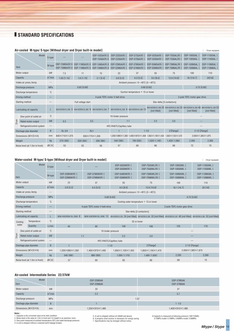
STANDARD SPECIFICATIONS
Air-cooled M-type/ S-type [Without dryer and Dryer built-in model]
Water-cooled M-type/ S-type [Without dryer and Dryer built-in model]
Ambient pressure / 0~40˚C (5~40˚C)
Suction temperature + 15 or lower
Ambient pressure / 0~40˚C (5~40˚C)
4-pole TEFC motor V-belt drive
Full voltage start Star-delta [3 contactors]
Star-delta [3 contactors]
2-pole TEFC motor gear drive
4-pole TEFC motor V-belt drive 2-pole TEFC motor gear drive
NEW HISCREW OIL 2000 5
NEW HISCREW OIL 2000 8 NEW HISCREW OIL 2000 13
NEW HISCREW OIL 2000 6 NEW HISCREW OIL 2000 7 NEW HISCREW OIL 2000 8 NEW HISCREW OIL 2000 13NEW HISCREW OIL 2000 25
[not filled]NEW HISCREW OIL 2000 33
[not filled]NEW HISCREW OIL 2000 48
[not filled]
110
20[18]
2,360
75
OSP-110S5ALⅠOSP-110S6ALⅠ
OSP-110M5ALⅠOSP-110M6ALⅠ
NEW HISCREW OIL 2000 53[not filled]
Temperature
Quantity
Coolingwater
10 Under pressure
10 Under pressure
Model
kW
m3/min
MPa
B
mm
22
2.2
1
1,250×910×1,480
37
3.7
1 1/2
1,400×910×1,480
ItemOSP-22M5AKOSP-22M6AK
OSP-37M5AKOSP-37M6AK
Motor output
Capacity
Discharge pressure
Dischage pipe diameter
Dimensions (W×D×H)
Air-cooled Intermediate Series 22/37kW
1.57
110
20 [18]
2,260
72
OSP-110S5WLⅠOSP-110S6WLⅠ
OSP-110M5WLⅠOSP-110M6WLⅠ
NEW HISCREW OIL 2000 53 [not filled]
170
Notes :1. Capacity is the converted value at its inlet condition.2. Noise level is the value at 1.5m in front and 1m height in an anechoic room.3. Dew point measured at ambient temperature 30˚C and rated discharge pressure.4. A unit is shipped without a selected earth leakage breaker.
5. A unit is shipped without oil (55kW and above).6. A properly sized receiver is necessary for energy saving.7. Specifications may be changed without notice.
8.Capacity is measured at following pressure (100/110kW).0.75MPa model: 0.70MPa, 0.85MPa model: 0.80MPa.
2,050×1,365×1,875
Mtype / Stype 10
Model
kW
m3/min
―
MPa
˚C
―
―
L
˚C
L/min
˚C
kW
―
B
mm
kg
dB[A]
Item
0.69 [0.83]
Cooling water temperature + 13 or lower
100
18.1 [16.7]
2,200
69
2 1/2 [Flange]
2,050×1,365×1,875
OSP-100S5WLⅠOSP-100S6WLⅠ
OSP-100M5WLⅠOSP-100M6WLⅠ
75
12.6 [10.8]
100
1,850×1,150×1,470
1,460 (1,630)
66
OSP-75S5WL(R)ⅠOSP-75S6WL(R)Ⅰ
OSP-75M5WL(R)ⅠOSP-75M6WL(R)Ⅰ
55
9.5 [8.5]
NEW HISCREW OIL 2000 24 [not filled] NEW HISCREW OIL 2000 33 [not filled] NEW HISCREW OIL 2000 48 [not filled]
100
1,850×1,100×1,450
1,050(1,170)
65
OSP-55S5W(R)ⅠOSP-55S6W(R)Ⅰ
OSP-55M5W(R)ⅠOSP-55M6W(R)Ⅰ
HFC-R407C/Capillary tube
1.1 2.2 3.0
37
6.3 [5.5]
65
1,400×970×1,400
880 (950)
60
1 1/2
―
OSP-37M5W(R)ⅠOSP-37M6W(R)Ⅰ
22
3.8 [3.3]
45
1
1,200×890×1,260
540 (590)
57
―
OSP-22M5W(R)ⅠOSP-22M6W(R)Ⅰ
32 or lower
( )Dryer equipped.
( )Dryer equipped.
125
―
―
―
kW
m3/min
―
MPa
˚C
―
―
L
˚C
kW
―
B
mm
kg
dB[A]
930×770×1,200
0.69 [0.83] 0.75 [0.85]
0.75 [0.85]
100
18.1[16.7]
2,300
72
OSP-100S5ALⅠOSP-100S6ALⅠ
OSP-100M5ALⅠOSP-100M6ALⅠ
3.0
1,850×1,150×1,470
1,420(1,590)
69
75
12.6 [10.8]
OSP-75S5AL(R)Ⅰ OSP-75S6AL(R)Ⅰ
OSP-75M5AL(R)Ⅰ OSP-75M6AL(R)Ⅰ
2.2
1,850×1,100×1,450
1,020(1,140)
66
55
9.5 [8.5]
OSP-55S5A(R)ⅠOSP-55S6A(R)Ⅰ
OSP-55M5A(R)Ⅰ OSP-55M6A(R)Ⅰ
1,400×970×1,400
760(830)
60
37
6.3 [5.5]
OSP-37S5A(R)ⅠOSP-37S6A(R)Ⅰ
OSP-37M5A(R)ⅠOSP-37M6A(R)Ⅰ
22
3.8 [3.3]
1.1
1
1,200×890×1,260
540(590)
57
OSP-22S5A(R)ⅠOSP-22S6A(R)Ⅰ
OSP-22M5A(R)ⅠOSP-22M6A(R)Ⅰ
15
2.1 [2.4]
HFC-R407C/Capillary tube
330(360)
56
OSP-15S5A(R)ⅡOSP-15S6A(R)Ⅱ
OSP-15M5A(R)ⅡOSP-15M6A(R)Ⅱ
―
―
―
―
11
1.6 [1.75]
0.83 [0.69]
0.5
Rc1
320(350)
55
OSP-11M5A(R)ⅡOSP-11M6A(R)Ⅱ
―
7.5
1.03 [1.15]
0.3
Rc 3/4
840×710×1,075
275(300)
53
OSP-7.5M5A(R)ⅡOSP-7.5M6A(R)Ⅱ
1 1/2 2 [Flange] 2 1/2 [Flange]
2 [Flange]
Item
ModelS-type
M-type
S-type
M-type
Motor output
Capacity
Intake air press./temp.
Discharge pressure
Discharge temperature
Driving method
Starting method
Lubricating oil capacity
Motor output
Capacity
Intake air press./temp.
Discharge pressure
Discharge temperature
Driving method
Starting method
Lubricating oil capacity
Dischage pipe diameter
Dimensions (W×D×H)
Weight
Noise level (at 1.5m in front)
Dischage pipe diameter
Dimensions (W×D×H)
Weight
Noise level (at 1.5m in front)
Dry
erD
ryer
Dew point of outlet air
Rated motor output
Refrigerant/control system
Dew point of outlet air
Rated motor output
Refrigerant/control system
STANDARD SPECIFICATIONS
Air-cooled M-type/ S-type [Without dryer and Dryer built-in model]
Water-cooled M-type/ S-type [Without dryer and Dryer built-in model]
Ambient pressure / 0~40˚C (5~40˚C)
Suction temperature + 15 or lower
Ambient pressure / 0~40˚C (5~40˚C)
4-pole TEFC motor V-belt drive
Full voltage start Star-delta [3 contactors]
Star-delta [3 contactors]
2-pole TEFC motor gear drive
4-pole TEFC motor V-belt drive 2-pole TEFC motor gear drive
NEW HISCREW OIL 2000 5
NEW HISCREW OIL 2000 8 NEW HISCREW OIL 2000 13
NEW HISCREW OIL 2000 6 NEW HISCREW OIL 2000 7 NEW HISCREW OIL 2000 8 NEW HISCREW OIL 2000 13NEW HISCREW OIL 2000 25
[not filled]NEW HISCREW OIL 2000 33
[not filled]NEW HISCREW OIL 2000 48
[not filled]
110
20[18]
2,360
75
OSP-110S5ALⅠOSP-110S6ALⅠ
OSP-110M5ALⅠOSP-110M6ALⅠ
NEW HISCREW OIL 2000 53[not filled]
Temperature
Quantity
Coolingwater
10 Under pressure
10 Under pressure
Model
kW
m3/min
MPa
B
mm
22
2.2
1
1,250×910×1,480
37
3.7
1 1/2
1,400×910×1,480
ItemOSP-22M5AKOSP-22M6AK
OSP-37M5AKOSP-37M6AK
Motor output
Capacity
Discharge pressure
Dischage pipe diameter
Dimensions (W×D×H)
Air-cooled Intermediate Series 22/37kW
1.57
110
20 [18]
2,260
72
OSP-110S5WLⅠOSP-110S6WLⅠ
OSP-110M5WLⅠOSP-110M6WLⅠ
NEW HISCREW OIL 2000 53 [not filled]
170
Notes :1. Capacity is the converted value at its inlet condition.2. Noise level is the value at 1.5m in front and 1m height in an anechoic room.3. Dew point measured at ambient temperature 30˚C and rated discharge pressure.4. A unit is shipped without a selected earth leakage breaker.
5. A unit is shipped without oil (55kW and above).6. A properly sized receiver is necessary for energy saving.7. Specifications may be changed without notice.
8.Capacity is measured at following pressure (100/110kW).0.75MPa model: 0.70MPa, 0.85MPa model: 0.80MPa.
2,050×1,365×1,875
11
ItemModel
STANDARD SPECIFICATIONS
Easy to clean by removing the side cover.
Coupling adjustment is unnecessary.
Totally enclosed motor is built in, high for both reliability and efficiency.
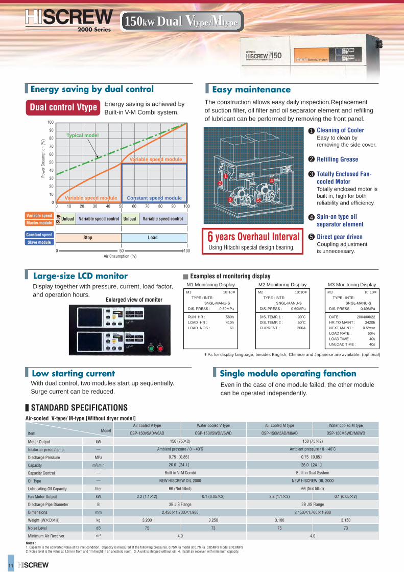
Energy saving is achieved by Built-in V-M Combi system.
Dual control Vtype
M1 Monitoring Display
M1 10:10* TYPE : INTE-
SNGL-MANU-S
DIS. PRESS : 0.69MPa
RUN HR : 580h
LOAD HR : 410h
LOAD NOS : 61
M3 Monitoring DisplayM2 Monitoring Display
10
10
20
20
30
30
40
40
50
50
60
60
70
70
80 90 100
80
90
100
00
500 100
Energy saving by dual control
Large-size LCD monitor
Easy maintenance
Low starting current Single module operating fanction
Display together with pressure, current, load factor, and operation hours.
Variable speed
Variable speed moduleVariable speed module
Typical model Typical model
Variable speed moduleVariable speed module
Master module Stop
Stop
Unload Unload
Load
Variable speed control Variable speed control
Constant speed moduleConstant speed module
Constant speed
Slave module
Air Cnsumption (%)
Pow
er C
nsum
ptio
n (%
)
Enlarged view of monitor
Examples of monitoring display
*As for display language, besides English, Chinese and Japanese are available. (optional)
The construction allows easy daily inspection.Replacement of suction filter, oil filter and oil separator element and refilling of lubricant can be performed by removing the front panel.
With dual control, two modules start up sequentially. Surge current can be reduced.
Even in the case of one module failed, the other module can be operated independently.
Direct gear driven
Spin-on type oil separator element
Cleaning of Cooler
Refilling Grease
Totally Enclosed Fan-cooled Motor
M2 10:10* TYPE : INTE-
SNGL-MANU-S
DIS. PRESS : 0.69MPa
DIS. TEMP. 1 : 90˚C
DIS. TEMP. 2 : 50˚C
CURRENT : 200A
M3 10:10* TYPE : INTE-
SNGL-MANU-S
DIS. PRESS : 0.69MPa
DATE : 2004/06/22
HR.TO MAINT : 3420h
NEXT MAINT : 0.5Year
LOAD RATE : 50%
LOAD TIME : 40s
UNLOAD TIME : 40s
Using Hitachi special design bearing.6 years Overhaul Interval
Notes : 1. Capacity is the converted value at its inlet condition. Capacity is measured at the following pressures. 0.75MPa model at 0.7MPa 0.85MPa model at 0.8MPa2. Noise level is the value at 1.5m in front and 1m height in an anechoic room. 3. A unit is shipped without oil. 4. Install air receiver with minimum capacity.
150 (75×2)
Ambient pressure / 0~40˚C
0.75〔0.85〕
26.0〔24.1〕
Built in Dual System
NEW HISCREW OIL 2000
66 (Not filled)
3B JIS Flange
2,450×1,700×1,900
4.0
Air cooled M type
OSP-150M5AD/M6AD
2.2 (1.1×2)
3,100
75
Water cooled M type
OSP-150M5WD/M6WD
0.1 (0.05×2)
3,150
73
150 (75×2)
Ambient pressure / 0~40˚C
0.75〔0.85〕
26.0〔24.1〕
Built in V-M Combi
NEW HISCREW OIL 2000
66 (Not filled)
3B JIS Flange
2,450×1,700×1,900
4.0
Water cooled V type
OSP-150V5WD/V6WD
0.1 (0.05×2)
3,250
73
Air cooled V type
OSP-150V5AD/V6AD
2.2 (1.1×2)
3,200
75
kW
―
MPa
m3/min
―
―
liter
kW
B
mm
kg
dB
m3
Motor Output
Intake air press./temp.
Discharge Pressure
Capacity
Capacity Control
Oil Type
Lubricating Oil Capacity
Fan Motor Output
Discharge Pipe Diameter
Dimensions
Weight (W×D×H)
Noise Level
Minimum Air Receiver
Air-cooled V-type/ M-type [Without dryer model]
150kW Dual150kW Dual
1
1
2
3
4
5
2
3
4
5
11
ItemModel
STANDARD SPECIFICATIONS
Easy to clean by removing the side cover.
Coupling adjustment is unnecessary.
Totally enclosed motor is built in, high for both reliability and efficiency.
Energy saving is achieved by Built-in V-M Combi system.
Dual control Vtype
M1 Monitoring Display
M1 10:10* TYPE : INTE-
SNGL-MANU-S
DIS. PRESS : 0.69MPa
RUN HR : 580h
LOAD HR : 410h
LOAD NOS : 61
M3 Monitoring DisplayM2 Monitoring Display
10
10
20
20
30
30
40
40
50
50
60
60
70
70
80 90 100
80
90
100
00
500 100
Energy saving by dual control
Large-size LCD monitor
Easy maintenance
Low starting current Single module operating fanction
Display together with pressure, current, load factor, and operation hours.
Variable speed
Variable speed moduleVariable speed module
Typical model Typical model
Variable speed moduleVariable speed module
Master module Stop
Stop
Unload Unload
Load
Variable speed control Variable speed control
Constant speed moduleConstant speed module
Constant speed
Slave module
Air Cnsumption (%)
Pow
er C
nsum
ptio
n (%
)
Enlarged view of monitor
Examples of monitoring display
*As for display language, besides English, Chinese and Japanese are available. (optional)
The construction allows easy daily inspection.Replacement of suction filter, oil filter and oil separator element and refilling of lubricant can be performed by removing the front panel.
With dual control, two modules start up sequentially. Surge current can be reduced.
Even in the case of one module failed, the other module can be operated independently.
Direct gear driven
Spin-on type oil separator element
Cleaning of Cooler
Refilling Grease
Totally Enclosed Fan-cooled Motor
M2 10:10* TYPE : INTE-
SNGL-MANU-S
DIS. PRESS : 0.69MPa
DIS. TEMP. 1 : 90˚C
DIS. TEMP. 2 : 50˚C
CURRENT : 200A
M3 10:10* TYPE : INTE-
SNGL-MANU-S
DIS. PRESS : 0.69MPa
DATE : 2004/06/22
HR.TO MAINT : 3420h
NEXT MAINT : 0.5Year
LOAD RATE : 50%
LOAD TIME : 40s
UNLOAD TIME : 40s
Using Hitachi special design bearing.6 years Overhaul Interval
Notes : 1. Capacity is the converted value at its inlet condition. Capacity is measured at the following pressures. 0.75MPa model at 0.7MPa 0.85MPa model at 0.8MPa2. Noise level is the value at 1.5m in front and 1m height in an anechoic room. 3. A unit is shipped without oil. 4. Install air receiver with minimum capacity.
150 (75×2)
Ambient pressure / 0~40˚C
0.75〔0.85〕
26.0〔24.1〕
Built in Dual System
NEW HISCREW OIL 2000
66 (Not filled)
3B JIS Flange
2,450×1,700×1,900
4.0
Air cooled M type
OSP-150M5AD/M6AD
2.2 (1.1×2)
3,100
75
Water cooled M type
OSP-150M5WD/M6WD
0.1 (0.05×2)
3,150
73
150 (75×2)
Ambient pressure / 0~40˚C
0.75〔0.85〕
26.0〔24.1〕
Built in V-M Combi
NEW HISCREW OIL 2000
66 (Not filled)
3B JIS Flange
2,450×1,700×1,900
4.0
Water cooled V type
OSP-150V5WD/V6WD
0.1 (0.05×2)
3,250
73
Air cooled V type
OSP-150V5AD/V6AD
2.2 (1.1×2)
3,200
75
kW
―
MPa
m3/min
―
―
liter
kW
B
mm
kg
dB
m3
Motor Output
Intake air press./temp.
Discharge Pressure
Capacity
Capacity Control
Oil Type
Lubricating Oil Capacity
Fan Motor Output
Discharge Pipe Diameter
Dimensions
Weight (W×D×H)
Noise Level
Minimum Air Receiver
Air-cooled V-type/ M-type [Without dryer model]
150kW Dual150kW Dual
1
1
2
3
4
5
2
3
4
5
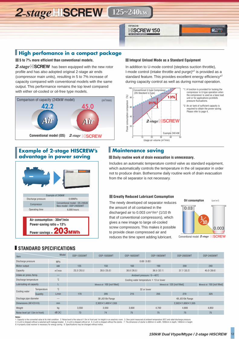
Notes :1. Capacity is the converted value at its inlet condition. 2. Noise level is the value at 1.5m in front and 1m height in an anechoic room. 3. Dew point measured at ambient temperature 30˚C and rated discharge pressure.4. A unit is shipped without a selected earth leakage breaker. 5. A unit is shipped without oil. 6. A unit is shipped without the starter. 7. The dimension of starter is 600mm in width, 1000mm in depth, 1400mm in height.8. A properly sized receiver is necessary for energy saving. 9. Specifications may be changed without notice.
150kW Dual Vtype/Mtype / 2-stage HISCREW
High perfomance in a compact package
12
Example of 240kWDischarge pressure 0.69MPa
Operating time 6,000 hours
Compressor Conventional model : OS-240U6New model : OSP-240S6WT
100
60
80
40
20
21%
13%
0 10 20 30 40 50
Usage air volume (m3/min)
Conventional U-type Compressor (OS Standard U-type)
Example 240 kW
Conventional model (OS)
(m3/min)Comparison of capacity (240kW model)
Conventional model
(cm3/m3) Oil consumption
ItemModel
MPa
kW
m3/min
―
˚C
L
˚C
L/min
―
mm
kg
dB[A]
OSP-125S5WT OSP-150S6WT OSP-160S5WT OSP-190S6WT OSP-200S5WT OSP-240S6WT
125
23.3(20.5)
150
28.5(25.0)
160
30.0(26.5)
190
36.5(32.1)
200
37.7(33.2)
240
45.0(39.6)
0.69 (0.83)
32 or lower
170 205 215 255 270 325
3B JIS10k Flange 4B JIS10k Flange
2,303×1,400×1,555 2,503×1,650×1,555
3,550 3,550 3,600 4,700 4,800 4,850
73 74 75 75 75 75
Air consumption : 30m3/minPower-saving ratio = 13%
Power savings = 203MWh
Maintenance savingExample of 2-stage HISCREW’s advantage in power saving
42.2 45.0
Air AirAir Air
110
0.03
0.003
STANDARD SPECIFICATIONS
Discharge pressure
Motor output
Capacity
Intake air press./temp.
Discharge temperature
Lubricating oil capacity
Temperature
QuantityCooling water
Dischage pipe diameter
Dimensions (W×D×H)
Weight
Noise level (at 1.5m in front)
Ambient pressure / 0~40˚C
Cooling water temperature + 13 or lower
Mineral oil 100 [not filled] Mineral oil 120 [not filled] Mineral oil 150 [not filled]
Pow
er c
onsu
mpt
ion
com
paris
on(%)
Includes an automatic temperature control valve as standard equipment, which automatically controls the temperature in the oil separator in order not to produce drain. Bothersome daily routine work of drain evacuation from the oil separator is not necessary.
■Daily routine work of drain evacuation is unnecessary.
has been equipped with the new rotor profile and has also adopted original 2-stage air ends (compressor main units), resulting in 5 to 7% increase of capacity compared with conventional models with the same output. This performance remains the top level compared with either oil-cooled or oil-free type models.
■5 to 7% more efficient than conventional models.
In addition to U-mode control (stepless suction throttle), I-mode control (intake throttle and purge)*1 is provided as a standard feature. This provides excellent energy efficiency*2 during capacity control as well as during normal operation.
■ Integral Unload Mode as a Standard Equipment
The newly developed oil separator reduces the amount of oil contained in the discharged air to 0.003 cm3/m3 (1/10 th that of conventional compressors), which gives a new image to large oil-cooled screw compressors. This makes it possible to provide clean compressed air and reduces the time spent adding lubricant.
■Greatly Reduced Lubricant Consumption
*1: A function is provided for locking the compressor in U-type operation when the compressor is used as a base load unit or for applications prohibits pressure fluctuations.
*2: An air tank of sufficient capacity is required to obtain the power saving.Please refer to page 4.
125~240kW125~240kW
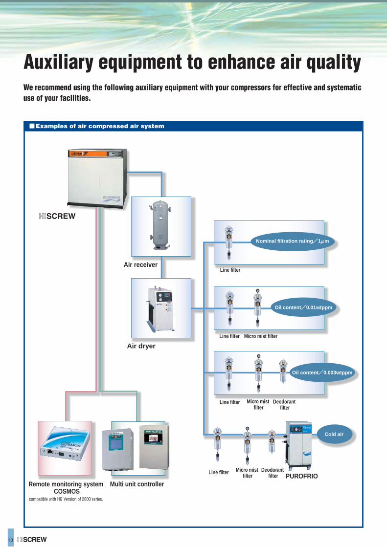
13
Auxiliary equipment to enhance air qualityWe recommend using the following auxiliary equipment with your compressors for effective and systematic use of your facilities.
Examples of air compressed air system
Line filter
Line filter Micro mist filter
Deodorant filter
Remote monitoring system COSMOS
compatible with HG Version of 2000 series.
Multi unit controller
Air receiver
Air dryer
Micro mist filter
Line filter
Deodorant filter
Micro mist filter
Line filter
Oil content/0.01wtppm
Oil content/0.003wtppm
Cold air
Nominal filtration rating/1 m
PUROFRIO
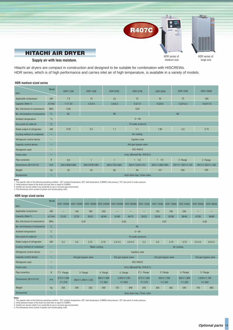
14
HDR series of medium size
HDR series of large size
ModelHDR-15AE HDR-22AE HDR-37AE HDR-55AE HDR-75AE HDR-100AE
2.4/2.8 3.9/4.2
0.97
5~40
10 under pressure
Air cooling
Capillary tube
Hot gas bypass valve
HFC-R407C
Ivory (Munsell No. 5Y8.5/1)
Auto drain trap / Drain valve
6.5/7.0 9.2/9.5 12.8/13.4
80 60
16.8/17.6
15 22 37 55 75 100
0.5 1.1 1.1 1.85 3.0 3.75
1 1 1 1/2 1 1/2 2 Flange 2 Flange
54 58 94 127 205 245
303×678×681 303×753×681 303×1,033×751 303×1,083×981 431×1,183×1,124 491×1,323×1,164
Item
HDR medium-sized series
Applicable compressor
Capacity (Note 1)
Max. inlet pressure of compressed air
Max. inlet temperature of compressed air
Ambient temperature
Dew point of outlet air
Rated output of refrigerator
Cooling method of condenser
Refrigerant control device
Capacity control device
Refrigerant used
Finish color
Pipe conection
Dimensions (W×D×H)
Weight
Accessories
kW
m3/min
MPa
˚C
˚C
˚C
kW
ー
ー
ー
ー
ー
B
mm
kg
ー
ModelHDR-120WE
21/25
0.97 0.970.93
2~40
10 under pressure
Water cooling Air cooling
Capillary tube
Hot gas bypass valve
HFC-R407C
Ivory (Munsell No. 5Y8.5/1)
Auto drain trap / Drain valve
60
2.2
250
672×1,260
×1,276
HDR-240WE
42/49
540
905×1,969
×1,583
HDR-240AE
38/45
540
905×1,969
×1,583
HDR-120AE
20/23
255
672×1,260
×1,276
HDR-300WE
51/60
HDR-380WE
64/75
720 840
HDR-150WE
27/31
3.0 2.2×2 3.0×2
0.93
HDR-300AE
47/55
HDR-380AE
59/69
740 860
2,020×1,100
×1,650
2.2×2 3.0×22.2
HDR-150AE
25/30
358
950×1,290
×1,332
3.0
HDR-190AE
32/38
362
3.75 3.75
348
HDR-190WE
35/41
ー 240 240ー ー ー 150 ー ー 150 190190
3.75 3.75
352
950×1,290×1,332
Item
HDR large-sized series
Applicable compressor
Capacity (Note 1)
Max. inlet pressure of compressed air
Max. inlet temperature of compressed air
Ambient temperature
Dew point of outlet air
Rated output of refrigerator
Cooling method of condenser
Refrigerant control device
Capacity control device
Refrigerant used
Finish color
Pipe conection
Dimensions (W×D×H)
Weight
Accessories
Notes:1. The capacity refer to the following operating condition : 32℃ ambient temperature, 40℃ inlet temperature, 0.69MPa inlet pressure, 10℃ dew point of under pressure.2. Initial pressure losses of the dryers are less than or equal to 0.03MPa3. Contact our service outlet if you would like to use in corrosive gas environment.4. The dimensions show surface of panels (not include piping, bolt)
kW
m3/min
MPa
℃
℃
℃
kW
ー
ー
ー
ー
ー
B
mm
kg
ー
Supply air with less moisture.
HITACHI AIR DRYER
HDR-7.5AE
7.5
1.1/1.34
0.93
65
0.25
3/4
33
255×656×680
2,020×1,100
×1,650
Hot gas bypass valve Hot gas bypass valve Hot gas bypass valve
Hitachi air dryers are compact in construction and designed to be suitable for combination with HISCREWs.HDR series, which is of high performance and carries inlet air of high temperature, is available in a variety of models.
Optional parts
R407CR407C
Notes:1. The capacity refer to the following operating condition : 32℃ ambient temperature, 40℃ inlet temperature, 0.69MPa inlet pressure, 10℃ dew point of under pressure.2. Initial pressure losses of the dryers are less than or equal to 0.03MPa3. Contact our service outlet if you would like to use in corrosive gas environment.4. The dimensions show surface of panels (not include piping, bolt)
4 Flange 4 Flange5 Flange 5 Flange3 Flange3 Flange 2 2 12 2
1 Flange Flange
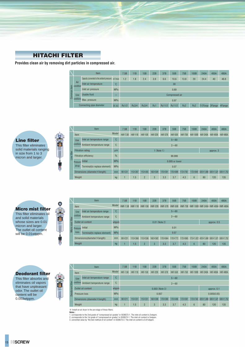
15
Line filter
Micro mist filter
Deodorant filter
※ Install an air dryer in the pre-stage of these filters.Notes :1. corresponds to the 2nd grade of "compressed air grades" in ISO8573-1. The inlet oil content is 3wtppm.2. corresponds to the 1st grade of "compressed air grades" in ISO8573-1. The inlet oil content is 3wtppm.3. converted value by "the test method of oil content" in ISO8573-2. The inlet oil content is 0.01wtppm.
Item
Capacity (converted to the ambient pressure)
Inlet air temperature
Inlet air pressure
Usable fluid
Max. pressure
Connecting pipe diameter
7.5B 11B 15B 22B 37B 55B 75B 100B 240A 400A 480A
1.2 1.8 2.4 3.9 6.6 10.6 13.8 20 24.4 40 48.8
Rc1/2 Rc3/4 Rc3/4 Rc1 Rc11/2 Rc11/2 Rc2 Rc2 21/2Flange 3Flange 4Flange
30
0.69
Compressed air
0.97
℃
B(A)
ー
m3/min
MPa
MPa
This filter eliminates solid materials ranging in size from 1 to 3 micron and larger.
This filter eliminates oil and solid materials whose sizes are 0.01 micron and larger.The outlet oil content will be 0.01wtppm.
This filter absorbs and eliminates oil vapors that have unpleasant odor. The outlet oil content will be 0.003wtppm.
Com
mon
item
Useconditions
Aircondition
Item
Inlet air temperature range
Ambient temperature range
Initial
Terminal(to replace element)
Outlet oil content
Dimensions(diameter×length)
Weight
7.5B 11B 15B 22B 37B 55B 75B 100B 240A 400A 480A
90×231 115×368 115×536 160×582 170×664 170×772 173×865 173×1,022 420×1,690 500×1,521 500×1,752
HMF-7.5B HMF-11B HMF-15B HMF-22B HMF-37B HMF-55B HMF-75B HMF-100B HMF-240A HMF-400A HMF-480A
5~60
2~60
0.01
0.07
0.01(Note 2) approx. 0.5
ModelItem
1 1.5 2 3 3.3 3.7 4.3 6 80 120 135
℃
℃
wtppm
MPa
MPa
mm
kg
Mic
ro m
ist f
ilter
Useconditions
Pressureloss
Item
Inlet air temperature range
Ambient temperature range
Outlet oil content
Pressure loss
Dimensions (diameter×length)
Weight
7.5B 11B 15B 22B 37B 55B 75B 100B 240A 400A 480A
90×211 115×231 115×231 160×308 170×390 170×498 173×591 173×748 420×1,690 500×1,521 500×1,752
1 1.5 2 3 3.3 3.7 4.3 6 80 120 135
5~60
2~60
0.003(Note 3)
0.007
approx. 0.1
0.005{0.05}
ModelItem HKF-7.5B HKF-11B HKF-15B HKF-22B HKF-37B HKF-55B HKF-75B HKF-100B HKF-240A HKF-400A HKF-480A
℃
℃
wtppm
MPa
mm
kg
Deo
dora
nt fi
lter
Useconditions
Item
Inlet air temperature range
Ambient temperature range
Initial
Terminal(to replace element)
Filtration rating
Filtration efficiency
Dimensions (diameter×length)
Weight
7.5B 11B 15B 22B 37B 55B 75B 100B 240A 400A 480A
HAF-7.5B HAF-11B HAF-15B HAF-22B HAF-37B HAF-55B HAF-75B HAF-100B HAF-240A HAF-400A HAF-480A
90×231 115×287 115×455 160×509 170×591 170×699 173×792 173×949 420×1,690 500×1,521 500×1,752
1 1.5 2 3 3.3 3.7 4.3 6 80 120 135
1(Note 1) approx. 3
ModelItem
5~60
2~60
99.999
0.005 or lower
0.07
℃
℃
μm
%
MPa
MPa
mm
kg
Line
filte
r
Use conditions
Pressuredrop
Provides clean air by removing dirt particles in compressed air.
HITACHI FILTER

16
ItemModel
Applicable modelPressure range of normal operationShell capacityAmbient temperatureFluids handled
Drain exhausting method
Condensate exhaustion amountwhen solenoid
WeightDimensions (W×D×H)
Condensate level sensing method
MPaL℃―
―
―
mm
cm3
kg
OWS-1 ※OWS-1A OWS-2 ※OWS-2A OWSK-1
Over 22kW
Visual check with the drain gauge
Visual check withthe drain gauge
Level switch of electrostaticcapacitance type
Level switch of electrostaticcapacitance type
Visual check withthe drain gauge
Manual ManualAutomatic exhaustionby solenoid valve.
Automatic exhaustionby solenoid valve. Manual
― ― 640~800/1activation(20sec.)
100/1 activation(5sec) ―
394×350×1,086 442×360×800625×356×1,086 841×360×800 685×350×1.19342 3554 47 50
7.5~15kW (22/37kW 1.57MPa)
Oil and drain Oil and drain0~40 0~40
15 90.39~0.97 0.39~0.97
※ For these models, electric power source of single phase, 200V is necessary.
Useful for long time and continuous operations.
HITACHI OIL CLEANER
In oil flooded type screw compressors, removal of oil condensate is crucial. This oil cleaner is ingeniously designed so that the condensate is separated and purged during operation. Hitachi Oil Cleaner is ideal for applications where continuous operation is required, and where the usage capacity varies greatly.
■Standard specsMulti Unit Controller (MULTI ROLLER EX)
ItemModel
Power Supply
Frequency
Controlled Units
Dimensions (W×D×H)
Weight
Discharge Pressure
Control
External
Control
External
MR26-4E
Single-phase AC100V/200V(Common)
50/60Hz(Common)
MR26-8E MR26-12E
4 8 12
0 to 1 MPa(Digital Display)
Operation Answer, Shutdown
Start, Stop, External Forced Start-up, Flow Volume
Start, Stop, Load, PID Command
Start, Shutdown, Auto
500×200×900 (mm)
32 (kg)
500×200×1,200 (mm)
37 (kg)
400×200×600 (mm)
19 (kg)
■Standard specs
ItemModel
Power source
Frequency
Controllable number of units
Controllable width of discharge
Dimensions (W×D×H)
Weight
Discharge pressure
Control
External
Control
External
AC100V(-10%+10%)[AC200V is usable by connector switching.]
50/60Hz
SDR-2
2
0~1MPa
Remote setting, Remote operation
Operation, stop, failure, Remote operation
Operation, stop, load instruction
Operation, failure, automatic
Min.±0.02MPa (Note1)
300×160×400 (mm)
8.5 (kg)Notes:1. When setting the minimum width of the pressure, contact our agent separately.2. Compressors except those driven by inverters are controllable by this equipment.
Note: The specification of the control board could differ according to the air compressor model to be connected.
Alternate operation panel (Dual roller II)
● Various alternate and/lead-lag operation are applicable to S-type models, where AUTO function is not necessary.
● The large LCD and the touch panel have improved its user-friendliness. It has been downsized too. The built-in sensor has digitalized pressure setting, which facilitates piping work and adjustments.
● It comes equipped with functions of automatic restart just after momentary power failure, calendar operation, detailed memory of failures and long-term suspension.
● Central control to stop operation is possible. It comes equipped with input/output terminals for external control.
This is a highly functional new model of alternate operation panel, which can control 2 units of interchangeably. If the 2 units are operated as a main and a standby units, they will constitute a standby system. It is also useful for leveling off the operation hours of the 2 units.
This equipment enables to operate plural efficiently. It excludes unload operations of no use and levels operation hours of each unit.
UNIT CONTROLLER
Inpu
tO
utpu
tIn
put
Out
put
Optional parts
※OWSK-1A
Level switch of electrostaticcapacitance type
Automatic exhaustionby solenoid valve.
700~1,300/1activation(20 sec.)
908×379×1,19362
Oil and drain0~40
150.39~1.67
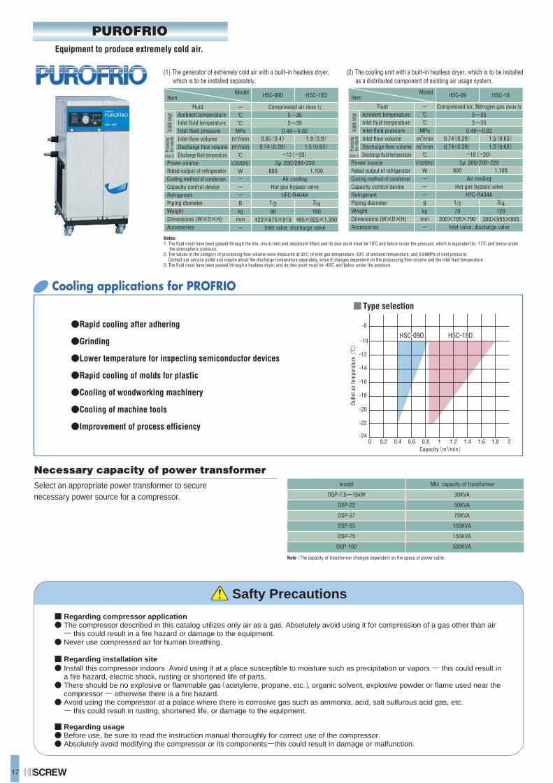
17
■ Regarding compressor application● The compressor described in this catalog utilizes only air as a gas. Absolutely avoid using it for compression of a gas other than air ー this could result in a fire hazard or damage to the equipment.● Never use compressed air for human breathing.
■ Regarding installation site● Install this compressor indoors. Avoid using it at a place susceptible to moisture such as precipitation or vapors ー this could result in a fire hazard, electric shock, rusting or shortened life of parts.● There should be no explosive or flammable gas(acetylene, propane, etc.), organic solvent, explosive powder or flame used near the compressor ー otherwise there is a fire hazard.● Avoid using the compressor at a palace where there is corrosive gas such as ammonia, acid, salt sulfurous acid gas, etc. ー this could result in rusting, shortened life, or damage to the equipment.
■ Regarding usage● Before use, be sure to read the instruction manual thoroughly for correct use of the compressor.● Absolutely avoid modifying the compressor or its componentsーthis could result in damage or malfunction.
Safty Precautions
(1) The generator of extremely cold air with a built-in heatless dryer, which is to be installed separately.
(2) The cooling unit with a built-in heatless dryer, which is to be installed as a distributed component of existing air usage system.
Model HSC-09D HSC-18D
Fluid Compressed air (Note 1)
5~355~35
0.49~0.92
Air coolingHot gas bypass valve
HFC-R404A
Inlet valve, discharge valve
-10(-20) 3φ 200/200・220
Rated output of refrigeratorCooling method of condenserCapacity control deviceRefrigerantPiping diameterWeightDimensions (W×D×H)
Ambient temperatureInlet fluid temperatureInlet fluid pressureInlet flow volumeDischarge flow volumeDischarge fluid temperature ℃
V(50/60Hz) Wー ー ー Bkg
mmー
ー ℃ ℃
MPam3/minm3/min
Item
0.85(0.4) 0.74(0.29)
800
1.8(0.9) 1.5(0.63)
1/290
3/4160
420×670×915 485×925×1,350
1,100
Model HSC-09 HSC-18
Fluid Compressed air, Nitrogen gas (Note 3)
5~355~35
0.49~0.92
Air coolingHot gas bypass valve
HFC-R404A
Inlet valve, discharge valve
-10(-20) 3φ 200/200・220
Rated output of refrigeratorCooling method of condenserCapacity control deviceRefrigerantPiping diameterWeight
Accessories
Ambient temperatureInlet fluid temperatureInlet fluid pressureInlet flow volumeDischarge flow volumeDischarge fluid temperature ℃
V(50/60Hz) Wー ー ー Bkg
mmー
ー ℃ ℃
MPam3/minm3/min
Item
0.74(0.29) 0.74(0.29)
800
1.5(0.63) 1.5(0.63)
1/270
3/4120
300×705×790 300×955×955
1,100Power sourcePower source
AccessoriesDimensions (W×D×H)
PUROFRIO
●Rapid cooling after adhering
●Grinding
●Lower temperature for inspecting semiconductor devices
●Rapid cooling of molds for plastic
●Cooling of woodworking machinery
●Cooling of machine tools
●Improvement of process efficiency
0 0.4 0.8 1.2 1.6 20.2 0.6 1 1.4 1.8Capacity(m3/min)
-12
-14
-16
-18
-20
-22
-24
Cooling applications for PROFRIO
-10
-8
HSC-09DHSC-09D HSC-18DHSC-18D
■Type selection
Equipment to produce extremely cold air.
Outle
t air
tem
pera
ture
(℃)
Notes:1. The fluid must have been passed through the line, micro mist and deodorant filters and its dew point must be 10℃ and below under the pressure, which is equivalent to -17℃ and below under the atmospheric pressure.2. The values in the category of processing flow volume were measured at 30℃ of inlet gas temperature, 30℃ of ambient temperature, and 0.69MPa of inlet pressure. Contact our service outlet and inquire about the discharge temperature separately, since it changes dependent on the processing flow volume and the inlet fluid temperature.3. The fluid must have been passed through a heatless dryer, and its dew point must be -40℃ and below under the pressure.
Usabl
e rang
ePr
oces
sing
low vo
lume
(Note 2)
Usabl
e rang
ePr
oces
sing
low vo
lume
(Note 2)
Necessary capacity of power transformerSelect an appropriate power transformer to secure necessary power source for a compressor.
model
OSP-7.5~15kW
OSP-22
OSP-37
OSP-55
OSP-75
OSP-100
Min. capacity of transformer
30KVA
50KVA
75KVA
100KVA
150KVA
300KVA
Note : The capacity of transformer changes dependent on the specs of power cable.
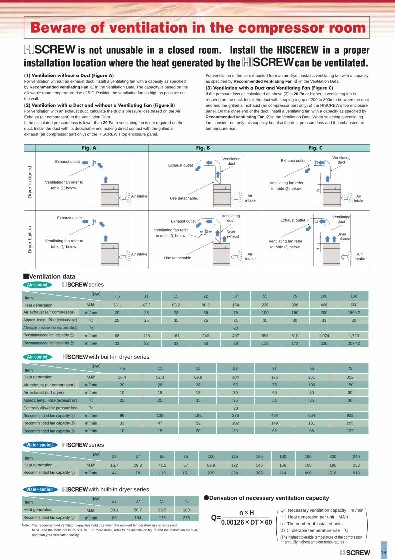
Beware of ventilation in the compressor room
18
Heat generation
Air exhaust (air compressor)
Allowable pressure loss (exhaust duct)
Approx. temp. Rise (exhaust air)
Recommended fan capacity
Recommended fan capacity
(kW) Item
(kW) Item
(kW) Item
(kW) Item
20
7.5
88
23
33.1
20
25
15
167
32
63.2
28
35
22
240
63
90.8
55
25
37
407
86
154
75
31
55
598
115
226
100
35
75
810
173
306
150
30
100
406
200
31
1,074
230
150
650
180×2
30
1,720
207×2
11
47.3
28
25
125
32
MJ/h
m3/min
˚C
Pa
m3/min
m3/min
■Ventilation dataseries
Heat generation
Air exhaust (air compressor)
Air exhaust (airf dryer)
Externally allowable pressure loss
Approx. temp. Rise (exhaust air)
Recommended fan capacity
Recommended fan capacity
Recommended fan capacity
7.5
96
33
10
11
138
47
15
15
185
52
20
22
276
102
39
37
464
149
62
55
664
181
66
75
36.4
20
10
25
52.3
28
18
25
69.9
28
18
35
104
55
30
25
175
75
50
31
251
100
30
35
352
150
30
30
932
295
122
MJ/h
m3/min
m3/min
˚C
Pa
m3/min
m3/min
m3/min
with built-in dryer series
Heat generation
Recommended fan capacity
22 37 55 75 100 125 150 160 190 200 240
16.7
44
29.3
78
41.5
110
57
151
82.9
220
122
324
146
388
156
414
185
490
195
516
233
619
MJ/h
m3/min
Heat generation
Recommended fan capacity
22 37 55 75
30.1
80
50.7
134
66.5
176
103
273
MJ/h
m3/min
series
with built-in dryer series
Note: The recommended ventilator capacities hold true when the ambient temperature rise is repressed to 5℃ and the static pressure is 0 Pa . For more detail, refer to the installation figure and the instruction manual, and plan your ventilation facility.
20
(1) Ventilation without a Duct (Figure A)For ventilation without an exhaust duct, install a ventilating fan with a capacity as specified by Recommended Ventilating Fan 1 in the Ventilation Data. The capacity is based on the allowable room temperature rise of 5˚C. Position the ventilating fan as high as possible on the wall.
(2) Ventilation with a Duct and without a Ventilating Fan (Figure B)For ventilation with an exhaust duct, calculate the duct's pressure loss based on the Air Exhaust (air compressor) in the Ventilation Data.If the calculated pressure loss is lower than 20 Pa, a ventilating fan is not required on the duct. Install the duct with its detachable end making direct contact with the grilled air exhaust (air compressor part only) of the HISCREW's top enclosure panel.
For ventilation of the air exhausted from an air dryer, install a ventilating fan with a capacity as specified by Recommended Ventilating Fan 3 in the Ventilation Data.
(3) Ventilation with a Duct and Ventilating Fan (Figure C)If the pressure loss as calculated as above (2) is 20 Pa or higher, a ventilating fan is required on the duct. Install the duct with keeping a gap of 200 to 300mm between the duct end and the grilled air exhaust (air compressor part only) of the HISCREW's top enclosure panel. On the other end of the duct, install a ventilating fan with a capacity as specified by Recommended Ventilating Fan 2 in the Ventilation Data. When selecting a ventilating fan, consider not only this capacity but also the duct pressure loss and the exhausted air temperature rise.
Air-cooled
Air-cooled
Water-cooled
Water-cooled
Q=
●Derivation of necessary ventilation capacity
Q:Necessary ventilation capacity m3/min
H:Heat generation per unit MJ/h
n:The number of installed units
DT:Tolerable temperature rise ℃
(The highest tolerable temperature of the compressor - annually highest ambient temperature)
n×H0.00126×DT×60
Dry
er e
xclu
ded
Dry
er b
uilt-
in
Fig. A
Exhaust outlet
Exhaust outlet
Fig. B Fig. C
hh
is not unusable in a closed room. Install the HISCEREW in a proper installation location where the heat generated by the can be ventilated.
Air intake Air intake
Air intake
Air intake
Air intake
Air intake
Ventilating fan refer to
table 1 below.
Ventilating fan refer to
table 1 below.
Ventilating fan refer
to table 3 below.
Ventilatingduct
Exhaust outletExhaust outlet
Exhaust outlet Exhaust outlet
Use detachable.
Use detachable.
Dryer exhaust Dryer
exhaust
Ventilating fan refer
to table 2 below.
Ventilating fan refer
to table 2 below.
Ventilatingduct
Ventilatingduct
Ventilatingduct
1
2
1
1
1
2
3
Printed in Japan(H)HC-E098T 0607
Specifications in this catalog are subject to change with or without notice, as Hitachi continues to develop the latest technologies and products for its customers.
Hitachi Screw Compressor is manufactured at a factory approved by Environmental Standard (ISO 14001) and Quality Standard (ISO9001) of International Organization for Standardization.
For further information, please contact your nearest sales representative.
ISO14001EC97J1107
ISO9001JQA-QM3443
ChinaHitachi (China) Ltd.18th Floor Beijing Fortune Building5 Dong San Huan Bei LuChao Yang District,Beijing 100004TEL : +86 (10) 6590-8111FAX : +86 (10) 6590-8110(Shanghai Office)(Hitachi (Shanghai) Trading Co., Ltd.)18th Floor, Rui Jin Building No.205, Maoming Road (S)Shanghai, 200020TEL : +86 (21) 6472-1002FAX : +86 (21) 6472-4990(Guangzhou Branch)3406, Office Tower, CITIC Plaza233 TianHe North Road, Guangzhou 510613TEL : +86 (20) 8752-1289FAX : +86 (20) 8752-1301
Hitachi East Asia Ltd.4th Floor, North Tower WorldFinance Centre, Harbour City, Canton Road, Tsim Sha Tsui, Kowloon Hong Kong.TEL : +852 2735-9218FAX : +852 2735-6793
(Taipei Branch)3rd Floor, Hung Kuo BuildingNo.167 Tun-Hwa North Road, Taipei (105) TaiwanTEL : +886 (2) 2718-3666FAX : +886 (2) 2718-8180
IndonesiaHitachi Asia Ltd. (Jakarta Office)10th Floor, Mid Plaza 1, JL. Jend.Sudirman Kav. 10-11, Jakarta 10220TEL : +62 (21) 574-4313FAX : +62 (21) 574-4312
MalaysiaHitachi Asia (Malaysia) Sdn. Bhd.Suite 17.3, Level 17, Menara IMC (Letter BoxNo.5) No. 8 Jalan Sultan Ismail, 50250, Kuala LumpurTEL : +60 (3) 2031-8751FAX : +60 (3) 2031-8758
PhilippinesHitachi Asia Ltd. (Philippines Branch)25th Floor, Pacific Star Building, Cor. Makati & Sen.Gil. Puyat Ave., Makati, Metro ManilaTEL : +63 (2) 819-7528, -7529FAX : +63 (2) 819-7539
SingaporeHitachi Asia Ltd.Power & Industrial Systems Group24 Jurong Port Road, #03-05 Cwt Distripark,Office Block, Singapore 619097TEL : +65-6305-7400FAX : +65-6305-7401
ThailandHitachi Asia (Thailand) Co., Ltd.18th Floor, Ramaland Building, 952 Rama IV Road Bangrak, Bangkok 10500TEL : +66 (2) 632-9292FAX : +66 (2) 632-9299
VietnamHitachi Asia Ltd. (Ho Chi Minh City Office)7th Floor, The Landmark, 5B Ton Duc ThangStreet District 1, Ho Chi Minh CityTEL : +84 (8) 829-9725FAX : +84 (8) 829-9729(Ha Noi Office)Sun Red River Bldg., 6th Floor, 23 Phan Chu Trinh Street Hoan Kiem District HanoiTEL : +84 (4) 933-3123FAX : +84 (4) 933-3125