Helmholtz resonance in a piezoelectric--hydraulic pump-based hybrid actuator€¦ · ·...
9
Helmholtz resonance in a piezoelectric–hydraulic pump-based hybrid actuator This article has been downloaded from IOPscience. Please scroll down to see the full text article. 2011 Smart Mater. Struct. 20 015010 (http://iopscience.iop.org/0964-1726/20/1/015010) Download details: IP Address: 141.211.173.82 The article was downloaded on 06/04/2012 at 16:59 Please note that terms and conditions apply. View the table of contents for this issue, or go to the journal homepage for more Home Search Collections Journals About Contact us My IOPscience
Transcript of Helmholtz resonance in a piezoelectric--hydraulic pump-based hybrid actuator€¦ · ·...
Helmholtz resonance in a piezoelectric–hydraulic pump-based hybrid actuator
This article has been downloaded from IOPscience. Please scroll down to see the full text article.
2011 Smart Mater. Struct. 20 015010
(http://iopscience.iop.org/0964-1726/20/1/015010)
Download details:
IP Address: 141.211.173.82
The article was downloaded on 06/04/2012 at 16:59
Please note that terms and conditions apply.
View the table of contents for this issue, or go to the journal homepage for more
Home Search Collections Journals About Contact us My IOPscience
IOP PUBLISHING SMART MATERIALS AND STRUCTURES
Smart Mater. Struct. 20 (2011) 015010 (8pp) doi:10.1088/0964-1726/20/1/015010
Helmholtz resonance in apiezoelectric–hydraulic pump-basedhybrid actuatorGi-Woo Kim and K W Wang
Department of Mechanical Engineering, University of Michigan, Ann Arbor, MI 48109, USA
E-mail: [email protected]
Received 21 June 2010, in final form 3 November 2010Published 9 December 2010Online at stacks.iop.org/SMS/20/015010
AbstractThis paper demonstrates that a hydraulically acting Helmholtz resonator can exist in apiezoelectric–hydraulic pump (PHP) based hybrid actuator, which in turn affects the volumetricefficiency of the PHP. The simulation and experimental results illustrate the effect of Helmholtzresonance on the flow rate performance of the PHP. The study also shows how to shift theHelmholtz resonant frequency to a higher value through changing parameters such as thecylinder diameter and the effective bulk modulus of the working fluid, which will improve thevolumetric efficiency and broaden the operating frequency range of the PHP actuator.
(Some figures in this article are in colour only in the electronic version)
Nomenclature
A ram (effective) area (m2)Cp capacitance of PZT stack (F)Cm compliance of PZT stack (=k−1
m )
C1 compliance of Helmholtz resonator (=k−11 )
C2 compliance of pumping chamber (=k−12 )
d1 diameter of double-acting hydraulic cylinder (m)d2 diameter of pumping chamber (m)d33 electro-mechanical charge (coupling) coefficienth1 height of double-acting hydraulic cylinder (m)h2 height of pumping chamber (m)i electric current (A)f frequency (Hz)km stiffness of PZT stack transducer (N m−1)k1 stiffness of Helmholtz resonator (N m−1)k2 stiffness of pumping chamber (N m−1)M2 effective mass of stiffener with diaphragm (kg)M1 effective mass of fluid (kg)N electro-mechanical conversion constantn number of PZT stack layerQ1 flow rate (cm3 s−1)s Laplace operatort thickness of PZT stack layer (m)Vo control volume of fluid cavity (m3)
VAC AC input voltage (Volt)x, x displacement and velocity (m, m s−1)Ze electrical impedanceZm mechanical impedanceZ i complex impedance of subscriptβe effective bulk modulus of working fluid (Pa)μ volumetric efficiency
1. Introduction
Hydraulic actuation systems play an important role inmany industrial applications. However, conventional electro-hydraulic actuation systems have many shortcomings andtechnical limitations that restrict performance. To overcomethese difficulties, new devices have been investigated to replacethe conventional actuation systems. One of the potentialalternatives is to utilize a piezoelectric–hydraulic pump (PHP)concept. The key idea of the PHP-based hybrid actuator (orPHP actuator) is to combine the advantages of piezoelectrictransducers (high power density and large load authority)and hydraulic systems (large stroke). Over the past years,several prototype PHP-based actuators have been introduced.Konishi et al [1] have developed a macro-scale PHP usinga piezoelectric stack actuator, and recognized that using aflexible diaphragm in the pumping chamber could increaseits bandwidth. Different versions of new actuation systems
0964-1726/11/015010+08$33.00 © 2011 IOP Publishing Ltd Printed in the UK & the USA1

Smart Mater. Struct. 20 (2011) 015010 G-W Kim and K W Wang
Figure 1. Schematic hydraulic circuit of the PHP actuator (gray area:suction flow side).
consisting of a PHP were designed [2–4]. Sirohi et al [5]used low voltage PZT stacks at higher frequencies to moreeffectively utilize their high power density. In addition, theysubstituted the ball-type check valves with reed valves toextend the bandwidth of the one-way valves. To overcomethe limitations of passive one-way valves, active check valveshave been investigated by several researchers [6, 7]. Theydeveloped a PHP that consists of a piezoelectric stack actuatorand two piezoelectric unimorph disc valves as one-way valves.Building on these previous efforts, researchers have recentlyinvestigated the feasibility of using PHP actuators in variousindustrial applications; one example is to manufacture a PHPfor advanced automotive powertrain control systems [8]. Theprimary challenge here is to develop a high-performance PHPactuator that can satisfy specific requirements, especially flowrate. Most previous research efforts to improve the flowrate of PHP actuators have focused on increasing the drivingfrequency up to a few kHz, based on the assumption thatthe flow rate of the PHP actuator will be proportional to thedriving frequency [5]. However, the flow rate of a PHP actuatorfluctuates in the high frequency range. The most likely reasonsfor flow rate fluctuation may be due to the bandwidth limitationof one-way valves and unknown resonances in the system.Moreover, the demand for a high operating frequency requiresa high current capacity driver to compensate for the largecapacitive load (10–50 μF) of the PZT stack transducers. Thistypically restricts the development of efficient and compactsystems, which is required in many industrial applications.Therefore, it is preferable to develop a high-performance PHPactuator that can operate effectively and efficiently in therelatively lower frequency range (i.e. a few hundred Hz).
2. Problem statement and objective
A schematic diagram of the testbed PHP actuator used in thisresearch is illustrated in figure 1. To have a compact design,this hybrid actuator needs to be a stand-alone device, featuringa self-constrained hardware configuration. A hydraulictransmission line (i.e. suction pipe) is connected to the
Figure 2. Configuration of the stand-alone PHP actuator.
chambers on both sides of the double-acting hydraulic cylinderto cancel the initial force caused by the gas accumulatorpressure. The rigid pipe with a diameter of 0.005 m isdesigned to match the outlet impedance (i.e. the outlet portsize is also �0.005 m). This hardware configuration makesthe head side of the double-acting hydraulic cylinder act asan oil reservoir, as opposed to conventional oil tanks. Thecompactness requirement also rules out the option of usingstandard commercial accumulators. Instead, in this researcha miniature gas accumulator is incorporated by using a rubberdiaphragm. Based on this hydraulic circuit, the prototype PHPactuator is designed and fabricated, as shown in figure 2. Asillustrated, this stand-alone prototype allows the eliminationof fluid line dynamics and minimizes the flow resistance andopportunity of air inflow.
An approximation method using a hydraulic cylinderattached to the PHP actuator is often utilized to evaluate theflow rate performance of the PHP actuator. The assumptionis that the pressure-rise rate of the hydraulic cylinder becomesnearly zero during the fast stroke without loading:
P = βe
(Vo + A1x)(Q1 − A1 x) ≈ 0 (1)
where βe is the effective bulk modulus, Vo is the controlvolume, A1 is the effective (ram) area of cylinder, x and x arethe displacement (i.e. stroke) and average velocity of cylinder,respectively; Q1 represents the flow rate. From equation (1),the no-load flow rate can be estimated as follows:
Q1 = A1x . (2)
Since the PHP is a positive displacement type pump thatutilizes a combination of the reciprocating action of a flexiblediaphragm and one-way check valves, this pump enables thedisplacement of fluid by trapping a small fixed amount of fluidin the discharging side. Accordingly, a theoretical flow rate(frequently referred to as the displacement of the pump) can bedefined as follows:
QTH = δπ D2
4f (3)
where δ is the effective stroke, D is the diameter of thepumping chamber, and f is the driving frequency. Once
2

Smart Mater. Struct. 20 (2011) 015010 G-W Kim and K W Wang
Figure 3. Typical flow rate performance of the PHP actuator(0.7 MPa accumulator pressure, 120 V).
the theoretical flow rate is defined, the volumetric efficiencybecomes one of the key indices for evaluating the flow rateperformance of positive displacement type pumps:
η = Q1
QTH. (4)
To explain the volumetric efficiency, the typical flow rateperformance of the prototype PHP actuator is illustrated infigure 3, showing the two flow rates defined in equations (2)and (3). It is obvious that the differences between thetheoretical flow rate and the actual measured flow rate aregradually increasing as frequency increases from 0 to 170 Hz.It is well recognized that this phenomenon is common indisplacement type pumps. In general, the primary factors thatnegatively affect the volumetric efficiency of the pump includeleakage into the back flow direction and external loads. Thevolumetric efficiency is also affected by the suction (i.e. inlet)flow dominated by the pipe size and pipe dynamics. At highfrequency, the small pipe size of the suction may cause a flowrestriction and deteriorated volumetric efficiency. In addition,the different pipe size between suction and discharge may leadto power transmission loss, known as impedance mismatching.As shown in figure 3, the measured actual flow rate suddenlydrops when the frequency is beyond a certain range (in thiscase, beyond 170 Hz), which leads to a significant degrading ofvolumetric efficiency. This undesirable phenomenon has beenreported in many other studies on PHP actuators using similarhydraulic circuits [5, 8–10]. Unfortunately, the aforementionedfactors do not explain this significant drop in volumetricefficiency. In order to facilitate driving the PHP in the lowfrequency range (1–300 Hz), this unwanted phenomenon hasto be first examined and the volumetric efficiency needs to beenhanced.
The objectives of this research are (a) to identify the mainreason for the degradation of the volumetric efficiency of thePHP actuator in the specific frequency range (e.g. >170 Hzfor the case shown in figure 3) and (b) to develop methodsto improve the PHP’s performance. A potential cause for thisdegradation phenomenon is hypothesized to be the Helmholtzresonance effect, due to the fact that the cavity size of the
Figure 4. Lumped model for the simplified suction flow rate side.
PHP cylinder is relatively large as compared to the pipe size (atypical Helmholtz resonator configuration). In this study, weverify such a hypothesis by analyzing a Helmholtz resonancemodel and comparing the results with test data. An equivalentelectric circuit model to describe the Helmholtz resonancecharacteristics is first synthesized. Simulation results aregenerated by utilizing the derived model and comparing toexperimental outcomes. We then identify means to shift theHelmholtz resonance to a higher frequency range throughparameter tuning of the model, which leads to the improvementof volumetric efficiency by expanding the effective operationalfrequency bandwidth.
3. Helmholtz resonance model
A Helmholtz resonator, generally known as a large cavityof fluid with an open port, is widely used in a varietyof applications to reduce unwanted sound or improvetransmission efficiency [11, 12, 14]. For instance, inorder to achieve large mass flow during the suction stroke,the Helmholtz resonator is widely used in current internalcombustion engines. In a similar manner, the characteristic ofsuction flow has a great effect on the flow rate performance ofthe positive displacement type pump since the discharge flowrate depends on the capability to circulate the working fluid,as mentioned in section 2. To explain the Helmholtz resonator,only the suction flow side is considered and simplified by usinga lumped model, as shown in figure 4. As noted in section 2,since the cavity size of the cylinder is relatively large comparedto the pipe size, it can very likely be viewed as the source ofthe Helmholtz resonator.
In this lumped model, the dynamics of the reed valves isexcluded based on the fact that the first natural frequency ofthe cantilever type reed valve immersed in fluid is estimatedto be much higher than the operational frequency range of thePHP actuator (below 250 Hz). Moreover, the motion of thereeds is generally limited by the stopper to prevent excessivedeformation, which implies that the orifice in reed valves isfully opening and will not affect the flow rate when the PZTstack transducer is operating. The stiffness of the flexiblediaphragm (e.g. spring steel with a thickness of 0.1 mm) isalso assumed to be very small and negligible since the effectivestroke is mainly governed by the PZT stack transducer. Fromthis lumped model, the large chamber on the low pressure(head) side of the double-acting hydraulic cylinder can act as a
3
Smart Mater. Struct. 20 (2011) 015010 G-W Kim and K W Wang
Helmholtz resonator consisting of an effective hydraulic springrate (k1) and a fluid mass (M1). It has been recognized thatthe fluid effective bulk modulus is a critical parameter that willaffect the apparent ‘stiffness’ of the working fluid [13, 15]. Theterm stiffness is frequently referred to as the effective hydraulicspring rate in a hydraulic control (or fluid power) system
ke = βe A2
Vo(5)
where βe is the effective bulk modulus, A represents the ramarea, and Vo is the control volume of the fluid cavity. Notethat the inverse of the effective hydraulic spring rate (hydrauliccompliance) is different from the hydraulic compliance in therate of pressure increase (i.e. continuity) equation [15]. Fromequation (5) and the definition of control volume (Vo = Ah),the effective hydraulic spring rates of the PHP actuator shownin figure 4 can be written as follows:
k1 = βe A1
h1= βe
πd21
4h1(6)
k2 = βe A2
h2= βe
πd22
4h2(7)
where di and hi , i = 1, 2 are the diameter and height of the twofluid cavities, respectively. In fact, the height of the Helmholtzcavity (h1) is a time-varying parameter due to stroking. Inthis analysis, the stroke (x) is set to be small (e.g. 0.005 m)to minimize its effect, and is assumed to be quasi-static. Fromequations (6) and (7), it is evident that the hydraulic springrate is a function of the effective bulk modulus and geometricvariables (such as the diameter of fluid cavity), which can beadjustable parameters for tuning the resonance frequency.
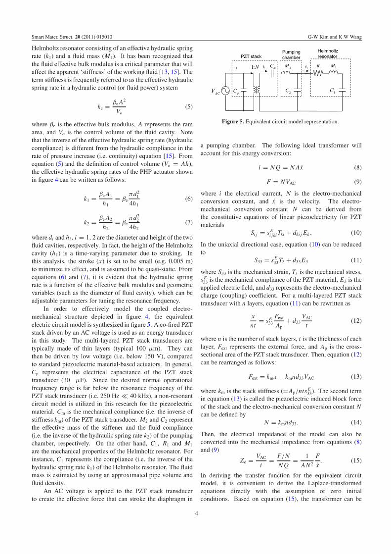
In order to effectively model the coupled electro-mechanical structure depicted in figure 4, the equivalentelectric circuit model is synthesized in figure 5. A co-fired PZTstack driven by an AC voltage is used as an energy transducerin this study. The multi-layered PZT stack transducers aretypically made of thin layers (typical 100 μm). They canthen be driven by low voltage (i.e. below 150 V), comparedto standard piezoelectric material-based actuators. In general,Cp represents the electrical capacitance of the PZT stacktransducer (30 μF). Since the desired normal operationalfrequency range is far below the resonance frequency of thePZT stack transducer (i.e. 250 Hz � 40 kHz), a non-resonantcircuit model is utilized in this research for the piezoelectricmaterial. Cm is the mechanical compliance (i.e. the inverse ofstiffness km) of the PZT stack transducer. M2 and C2 representthe effective mass of the stiffener and the fluid compliance(i.e. the inverse of the hydraulic spring rate k2) of the pumpingchamber, respectively. On the other hand, C1, R1 and M1
are the mechanical properties of the Helmholtz resonator. Forinstance, C1 represents the compliance (i.e. the inverse of thehydraulic spring rate k1) of the Helmholtz resonator. The fluidmass is estimated by using an approximated pipe volume andfluid density.
An AC voltage is applied to the PZT stack transducerto create the effective force that can stroke the diaphragm in
Figure 5. Equivalent circuit model representation.
a pumping chamber. The following ideal transformer willaccount for this energy conversion:
i = N Q = N Ax (8)
F = NVAC (9)
where i the electrical current, N is the electro-mechanicalconversion constant, and x is the velocity. The electro-mechanical conversion constant N can be derived fromthe constitutive equations of linear piezoelectricity for PZTmaterials
Si j = sEi jkl Tkl + dki j Ek . (10)
In the uniaxial directional case, equation (10) can be reducedto
S33 = sE33T3 + d33 E3 (11)
where S33 is the mechanical strain, T3 is the mechanical stress,sE
33 is the mechanical compliance of the PZT material, E3 is theapplied electric field, and d33 represents the electro-mechanicalcharge (coupling) coefficient. For a multi-layered PZT stacktransducer with n layers, equation (11) can be rewritten as
x
nt= sE
33
Fext
Ap+ d33
VAC
t(12)
where n is the number of stack layers, t is the thickness of eachlayer, Fext represents the external force, and Ap is the cross-sectional area of the PZT stack transducer. Then, equation (12)can be rearranged as follows:
Fext = kmx − kmnd33VAC (13)
where km is the stack stiffness (=Ap/ntsE33). The second term
in equation (13) is called the piezoelectric induced block forceof the stack and the electro-mechanical conversion constant Ncan be defined by
N = kmnd33. (14)
Then, the electrical impedance of the model can also beconverted into the mechanical impedance from equations (8)and (9)
Ze = VAC
i= F/N
N Q= 1
AN2
F
x. (15)
In deriving the transfer function for the equivalent circuitmodel, it is convenient to derive the Laplace-transformedequations directly with the assumption of zero initialconditions. Based on equation (15), the transformer can be
4
Smart Mater. Struct. 20 (2011) 015010 G-W Kim and K W Wang
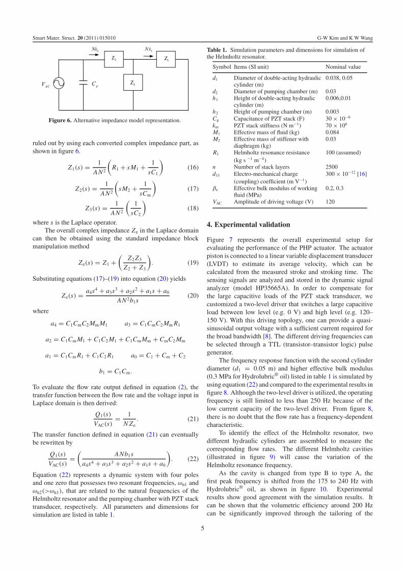
Figure 6. Alternative impedance model representation.
ruled out by using each converted complex impedance part, asshown in figure 6.
Z1(s) = 1
AN2
(R1 + sM1 + 1
sC1
)(16)
Z2(s) = 1
AN2
(sM2 + 1
sCm
)(17)
Z3(s) = 1
AN2
(1
sC2
)(18)
where s is the Laplace operator.The overall complex impedance Ze in the Laplace domain
can then be obtained using the standard impedance blockmanipulation method
Ze(s) = Z1 +(
Z2 Z3
Z2 + Z3
). (19)
Substituting equations (17)–(19) into equation (20) yields
Ze(s) = a4s4 + a3s3 + a2s2 + a1s + a0
AN2b1s(20)
where
a4 = C1CmC2 Mm M1 a3 = C1CmC2 Mm R1
a2 = C1Cm M1 + C1C2 M1 + C1CmMm + CmC2 Mm
a1 = C1Cm R1 + C1C2 R1 a0 = C1 + Cm + C2
b1 = C1Cm.
To evaluate the flow rate output defined in equation (2), thetransfer function between the flow rate and the voltage input inLaplace domain is then derived:
Q1(s)
VAC(s)= 1
N Ze. (21)
The transfer function defined in equation (21) can eventuallybe rewritten by
Q1(s)
VAC(s)=
(ANb1s
a4s4 + a3s3 + a2s2 + a1s + a0
). (22)
Equation (22) represents a dynamic system with four polesand one zero that possesses two resonant frequencies, ωn1 andωn2(>ωn1), that are related to the natural frequencies of theHelmholtz resonator and the pumping chamber with PZT stacktransducer, respectively. All parameters and dimensions forsimulation are listed in table 1.
Table 1. Simulation parameters and dimensions for simulation ofthe Helmholtz resonator.
Symbol Items (SI unit) Nominal value
d1 Diameter of double-acting hydrauliccylinder (m)
0.038, 0.05
d2 Diameter of pumping chamber (m) 0.03h1 Height of double-acting hydraulic
cylinder (m)0.006,0.01
h2 Height of pumping chamber (m) 0.003Cp Capacitance of PZT stack (F) 30 × 10−6
km PZT stack stiffness (N m−1) 70 × 106
M1 Effective mass of fluid (kg) 0.084M2 Effective mass of stiffener with
diaphragm (kg)0.03
R1 Helmholtz resonance resistance(kg s −1 m−4)
100 (assumed)
n Number of stack layers 2500d33 Electro-mechanical charge
(coupling) coefficient (m V−1)300 × 10−12 [16]
βe Effective bulk modulus of workingfluid (MPa)
0.2, 0.3
VAC Amplitude of driving voltage (V) 120
4. Experimental validation
Figure 7 represents the overall experimental setup forevaluating the performance of the PHP actuator. The actuatorpiston is connected to a linear variable displacement transducer(LVDT) to estimate its average velocity, which can becalculated from the measured stroke and stroking time. Thesensing signals are analyzed and stored in the dynamic signalanalyzer (model HP35665A). In order to compensate forthe large capacitive loads of the PZT stack transducer, wecustomized a two-level driver that switches a large capacitiveload between low level (e.g. 0 V) and high level (e.g. 120–150 V). With this driving topology, one can provide a quasi-sinusoidal output voltage with a sufficient current required forthe broad bandwidth [8]. The different driving frequencies canbe selected through a TTL (transistor–transistor logic) pulsegenerator.
The frequency response function with the second cylinderdiameter (d1 = 0.05 m) and higher effective bulk modulus(0.3 MPa for Hydrolubric® oil) listed in table 1 is simulated byusing equation (22) and compared to the experimental results infigure 8. Although the two-level driver is utilized, the operatingfrequency is still limited to less than 250 Hz because of thelow current capacity of the two-level driver. From figure 8,there is no doubt that the flow rate has a frequency-dependentcharacteristic.
To identify the effect of the Helmholtz resonator, twodifferent hydraulic cylinders are assembled to measure thecorresponding flow rates. The different Helmholtz cavities(illustrated in figure 9) will cause the variation of theHelmholtz resonance frequency.
As the cavity is changed from type B to type A, thefirst peak frequency is shifted from the 175 to 240 Hz withHydrolubric® oil, as shown in figure 10. Experimentalresults show good agreement with the simulation results. Itcan be shown that the volumetric efficiency around 200 Hzcan be significantly improved through the tailoring of the
5

Smart Mater. Struct. 20 (2011) 015010 G-W Kim and K W Wang
Figure 7. Measurement setup for evaluating flow rate performance.
Figure 8. Comparison of flow rate performance (d1 = 0.05 m;–, simulated; ◦, measured).
Helmholtz resonant frequency. Next, the effect of the effectivebulk modulus on Helmholtz resonance is also investigated byreplacing the working fluids. Since it is well recognized thatthe effective bulk modulus of the water-based Hydrolubric®
oil is higher than that of petroleum-based hydraulic oil, suchas DEXRON-III®, under the same pressure [13, 17], thesetwo fluids are used alternately as working fluids for the PHPactuator. As in figure 10, the simulated first peak frequency
Figure 9. Different Helmholtz cavities of the hydraulic cylinders.
Figure 10. Comparison of flow rate (Hydrolubric® oil) with respectto different Helmholtz cavities (��, type B measured; - - - -, type Bsimulated; ◦, type A measured; ——, type A simulated).
shown in figure 11 is shifted from 170 to 250 Hz with the Atype cylinder using the working fluid with the higher effectivebulk modulus. The experimental results also show goodagreement with the simulation predictions.
To further confirm the Helmholtz resonance effect inthe PHP actuator, the acoustic sound pressure level (SPL) isexperimentally measured by using a microphone. Figure 12shows the overall SPL measurement stand in an anechoicchamber, in is a shielded room designed to attenuatesound waves. Background noise is not considered in thismeasurement. Four microphones are located at 0.5 m fromthe longitudinal centers of the vertical planes forming thesmallest rectangle to measure the average sound pressure level.Air condenser type microphones (Larson Davis laboratoriesmodel, sensitivity range of 4–8 mV Pa−1) are used in thismeasurement. The formula for calculating the individual SPLis [14]
SPL = 10 log10
[PRMS
Pref
]2
dB (23)
where PRMS is the measured RMS sound pressure, Pref is thereference sound pressure (the commonly used reference sound
6
Smart Mater. Struct. 20 (2011) 015010 G-W Kim and K W Wang
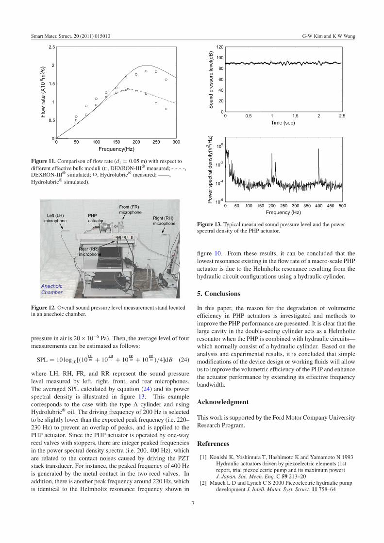
Figure 11. Comparison of flow rate (d1 = 0.05 m) with respect todifferent effective bulk moduli (��, DEXRON-III® measured; - - - -,DEXRON-III® simulated; ◦, Hydrolubric® measured; ——,Hydrolubric® simulated).
Figure 12. Overall sound pressure level measurement stand locatedin an anechoic chamber.
pressure in air is 20×10−6 Pa). Then, the average level of fourmeasurements can be estimated as follows:
SPL = 10 log10[(10LH10 + 10
RH10 + 10
FR10 + 10
RR10 )/4]dB (24)
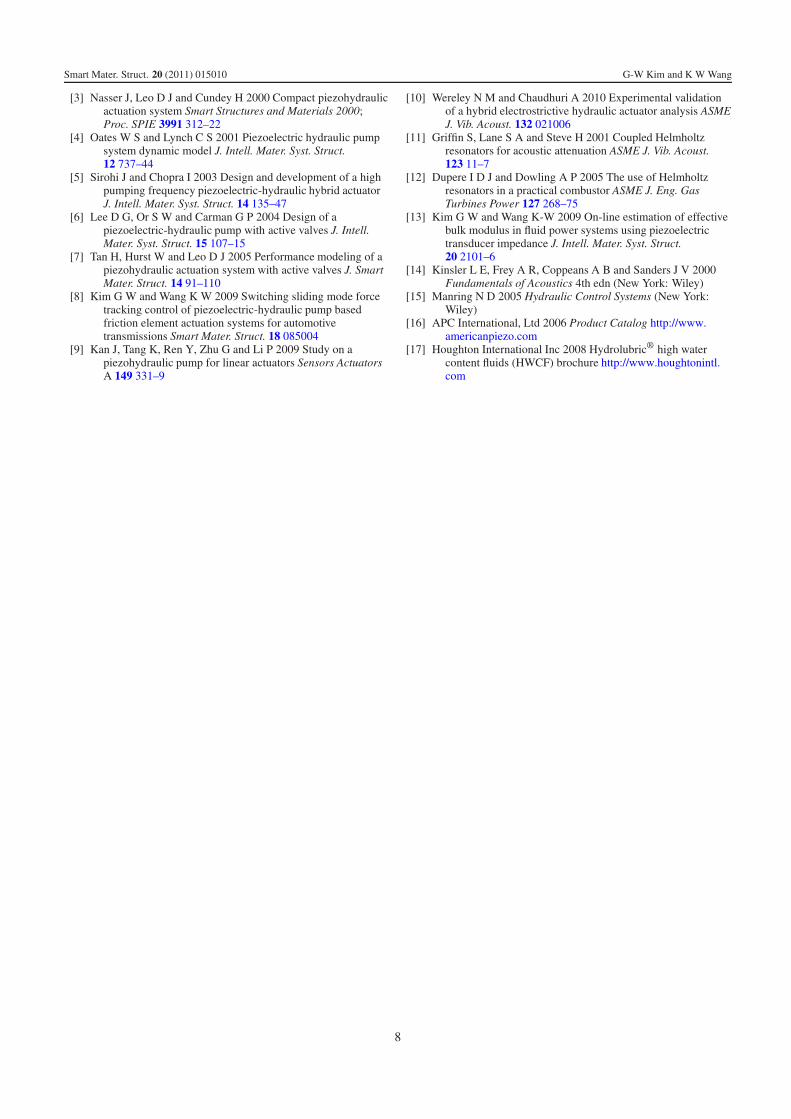
where LH, RH, FR, and RR represent the sound pressurelevel measured by left, right, front, and rear microphones.The averaged SPL calculated by equation (24) and its powerspectral density is illustrated in figure 13. This examplecorresponds to the case with the type A cylinder and usingHydrolubric® oil. The driving frequency of 200 Hz is selectedto be slightly lower than the expected peak frequency (i.e. 220–230 Hz) to prevent an overlap of peaks, and is applied to thePHP actuator. Since the PHP actuator is operated by one-wayreed valves with stoppers, there are integer peaked frequenciesin the power spectral density spectra (i.e. 200, 400 Hz), whichare related to the contact noises caused by driving the PZTstack transducer. For instance, the peaked frequency of 400 Hzis generated by the metal contact in the two reed valves. Inaddition, there is another peak frequency around 220 Hz, whichis identical to the Helmholtz resonance frequency shown in
Figure 13. Typical measured sound pressure level and the powerspectral density of the PHP actuator.
figure 10. From these results, it can be concluded that thelowest resonance existing in the flow rate of a macro-scale PHPactuator is due to the Helmholtz resonance resulting from thehydraulic circuit configurations using a hydraulic cylinder.
5. Conclusions
In this paper, the reason for the degradation of volumetricefficiency in PHP actuators is investigated and methods toimprove the PHP performance are presented. It is clear that thelarge cavity in the double-acting cylinder acts as a Helmholtzresonator when the PHP is combined with hydraulic circuits—which normally consist of a hydraulic cylinder. Based on theanalysis and experimental results, it is concluded that simplemodifications of the device design or working fluids will allowus to improve the volumetric efficiency of the PHP and enhancethe actuator performance by extending its effective frequencybandwidth.
Acknowledgment
This work is supported by the Ford Motor Company UniversityResearch Program.
References
[1] Konishi K, Yoshimura T, Hashimoto K and Yamamoto N 1993Hydraulic actuators driven by piezoelectric elements (1streport, trial piezoelectric pump and its maximum power)J. Japan. Soc. Mech. Eng. C 59 213–20
[2] Mauck L D and Lynch C S 2000 Piezoelectric hydraulic pumpdevelopment J. Intell. Mater. Syst. Struct. 11 758–64
7
Smart Mater. Struct. 20 (2011) 015010 G-W Kim and K W Wang
[3] Nasser J, Leo D J and Cundey H 2000 Compact piezohydraulicactuation system Smart Structures and Materials 2000;Proc. SPIE 3991 312–22
[4] Oates W S and Lynch C S 2001 Piezoelectric hydraulic pumpsystem dynamic model J. Intell. Mater. Syst. Struct.12 737–44
[5] Sirohi J and Chopra I 2003 Design and development of a highpumping frequency piezoelectric-hydraulic hybrid actuatorJ. Intell. Mater. Syst. Struct. 14 135–47
[6] Lee D G, Or S W and Carman G P 2004 Design of apiezoelectric-hydraulic pump with active valves J. Intell.Mater. Syst. Struct. 15 107–15
[7] Tan H, Hurst W and Leo D J 2005 Performance modeling of apiezohydraulic actuation system with active valves J. SmartMater. Struct. 14 91–110
[8] Kim G W and Wang K W 2009 Switching sliding mode forcetracking control of piezoelectric-hydraulic pump basedfriction element actuation systems for automotivetransmissions Smart Mater. Struct. 18 085004
[9] Kan J, Tang K, Ren Y, Zhu G and Li P 2009 Study on apiezohydraulic pump for linear actuators Sensors ActuatorsA 149 331–9
[10] Wereley N M and Chaudhuri A 2010 Experimental validationof a hybrid electrostrictive hydraulic actuator analysis ASMEJ. Vib. Acoust. 132 021006
[11] Griffin S, Lane S A and Steve H 2001 Coupled Helmholtzresonators for acoustic attenuation ASME J. Vib. Acoust.123 11–7
[12] Dupere I D J and Dowling A P 2005 The use of Helmholtzresonators in a practical combustor ASME J. Eng. GasTurbines Power 127 268–75
[13] Kim G W and Wang K-W 2009 On-line estimation of effectivebulk modulus in fluid power systems using piezoelectrictransducer impedance J. Intell. Mater. Syst. Struct.20 2101–6
[14] Kinsler L E, Frey A R, Coppeans A B and Sanders J V 2000Fundamentals of Acoustics 4th edn (New York: Wiley)
[15] Manring N D 2005 Hydraulic Control Systems (New York:Wiley)
[16] APC International, Ltd 2006 Product Catalog http://www.americanpiezo.com
[17] Houghton International Inc 2008 Hydrolubric® high watercontent fluids (HWCF) brochure http://www.houghtonintl.com
8