Digital hydraulic multi-pressure actuator – the … · Digital hydraulic multi-pressure actuator...
14
This is an electronic reprint of the original article. This reprint may differ from the original in pagination and typographic detail. Powered by TCPDF (www.tcpdf.org) This material is protected by copyright and other intellectual property rights, and duplication or sale of all or part of any of the repository collections is not permitted, except that material may be duplicated by you for your research use or educational purposes in electronic or print form. You must obtain permission for any other use. Electronic or print copies may not be offered, whether for sale or otherwise to anyone who is not an authorised user. Huova, Mikko; Aalto, Arttu; Linjama, Matti; Huhtala, Kalevi; Lantela, Tapio; Pietola, Matti Digital hydraulic multi-pressure actuator – the concept, simulation study and first experimental results Published in: INTERNATIONAL JOURNAL OF FLUID POWER DOI: 10.1080/14399776.2017.1302775 Published: 01/01/2017 Document Version Publisher's PDF, also known as Version of record Please cite the original version: Huova, M., Aalto, A., Linjama, M., Huhtala, K., Lantela, T., & Pietola, M. (2017). Digital hydraulic multi-pressure actuator – the concept, simulation study and first experimental results. INTERNATIONAL JOURNAL OF FLUID POWER, 18(3), 141-152. DOI: 10.1080/14399776.2017.1302775
Transcript of Digital hydraulic multi-pressure actuator – the … · Digital hydraulic multi-pressure actuator...
This is an electronic reprint of the original article.This reprint may differ from the original in pagination and typographic detail.
Powered by TCPDF (www.tcpdf.org)
This material is protected by copyright and other intellectual property rights, and duplication or sale of all or part of any of the repository collections is not permitted, except that material may be duplicated by you for your research use or educational purposes in electronic or print form. You must obtain permission for any other use. Electronic or print copies may not be offered, whether for sale or otherwise to anyone who is not an authorised user.
Huova, Mikko; Aalto, Arttu; Linjama, Matti; Huhtala, Kalevi; Lantela, Tapio; Pietola, Matti
Digital hydraulic multi-pressure actuator – the concept, simulation study and firstexperimental results
Published in:INTERNATIONAL JOURNAL OF FLUID POWER
DOI:10.1080/14399776.2017.1302775
Published: 01/01/2017
Document VersionPublisher's PDF, also known as Version of record
Please cite the original version:Huova, M., Aalto, A., Linjama, M., Huhtala, K., Lantela, T., & Pietola, M. (2017). Digital hydraulic multi-pressureactuator – the concept, simulation study and first experimental results. INTERNATIONAL JOURNAL OF FLUIDPOWER, 18(3), 141-152. DOI: 10.1080/14399776.2017.1302775
Full Terms & Conditions of access and use can be found athttp://www.tandfonline.com/action/journalInformation?journalCode=tjfp20
Download by: [Aalto-yliopiston kirjasto] Date: 11 April 2017, At: 02:15
International Journal of Fluid Power
ISSN: 1439-9776 (Print) 2332-1180 (Online) Journal homepage: http://www.tandfonline.com/loi/tjfp20
Digital hydraulic multi-pressure actuator – theconcept, simulation study and first experimentalresults
Mikko Huova, Arttu Aalto, Matti Linjama, Kalevi Huhtala, Tapio Lantela &Matti Pietola
To cite this article: Mikko Huova, Arttu Aalto, Matti Linjama, Kalevi Huhtala, Tapio Lantela & MattiPietola (2017): Digital hydraulic multi-pressure actuator – the concept, simulation study and firstexperimental results, International Journal of Fluid Power, DOI: 10.1080/14399776.2017.1302775
To link to this article: http://dx.doi.org/10.1080/14399776.2017.1302775
© 2017 The Author(s). Published by InformaUK Limited, trading as Taylor & FrancisGroup
Published online: 29 Mar 2017.
Submit your article to this journal
Article views: 79
View related articles
View Crossmark data

InternatIonal Journal of fluId Power, 2017http://dx.doi.org/10.1080/14399776.2017.1302775
KEYWORDSdigital hydraulics; hybrid actuator; integrated actuator
ARTICLE HISTORYreceived 29 october 2015 accepted 2 March 2017
© 2017 the author(s). Published by Informa uK limited, trading as taylor & francis Group.this is an open access article distributed under the terms of the Creative Commons attribution-nonCommercial-noderivatives license (http://creativecommons.org/licenses/by-nc-nd/4.0/), which permits non-commercial re-use, distribution, and reproduction in any medium, provided the original work is properly cited, and is not altered, transformed, or built upon in any way.
CONTACT Mikko Huova [email protected]
Digital hydraulic multi-pressure actuator – the concept, simulation study and first experimental results
Mikko Huovaa , Arttu Aaltoa, Matti Linjamaa , Kalevi Huhtalaa , Tapio Lantelab and Matti Pietolab
alaboratory of automation and Hydraulic engineering (aut), tampere university of technology (tut), tampere, finland; bdepartment of engineering design and Production, aalto university, espoo, finland
ABSTRACTThe decentralisation of hydraulic systems is a recent trend in industrial hydraulics. Speed variable drive is one concept where an actuator is driven by an integrated pump, thus removing the need for control valves or complex centralised variable displacement hydraulic units and long pipelines. The motivation for the development is the need to improve the energy efficiency and flexibility of drives. A similar solution to mobile hydraulics is not currently available. This paper studies a digital hydraulic approach, which includes a local hydraulic energy storage located together with the actuator, the means to convert efficiently energy from the storage to mechanical work and a small start-/stop-type pump unit sized according to mean power. The simulation results and first experimental results show that the approach has remarkable energy saving potential compared to traditional valve controlled systems, but further research is needed to improve the controllability.
OPEN ACCESS
Introduction
Many traditional hydraulic systems are based on a cen-tralised layout, where a single supply unit feeds a set of control valves, which in turn control the movement of multiple actuators. The supply unit is dimensioned so that the peak power requirements of simultaneously operating actuators are fulfilled. These systems have unique layouts and are specifically designed for a single purpose.
The flexibility and ease of commissioning in industrial and mobile hydraulic systems would improve greatly if the actuators and their supply systems were integrated into one unit with interfaces that are simple to work with. In such a system the change of a single actuator or addition of an actuator would not compromise the func-tionality or efficiency of the rest of the system. Industrial hydraulics is moving towards this direction through the introduction of speed-variable drives. However, mobile hydraulic systems, which are often characterised by high inertia loads, overrunning loadings and diesel engine as the prime mover, are still waiting for a practical solution.
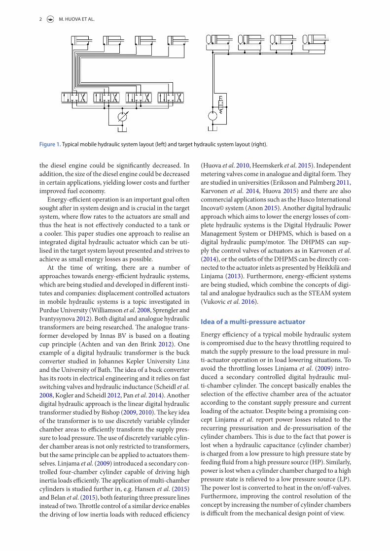
In typical mobile application, there is a centralised hydraulic supply unit as presented in the left side of Figure 1. In a typical valve controlled system, the control valves are located close to the supply unit. The hydraulic power is supplied to the actuators via long hoses and pipelines, which are sized according to the peak flow rates of the actuators. In many mobile hydraulic systems,
there are a number of actuators and numerous parallel hoses located in the boom of the machine. The hydraulic capacitance of the hoses reduces the controllability of the actuators and the hoses are a frequent point of fail-ure in the system. Another disadvantage of a traditional load sensing mobile hydraulic system is the way it loads the diesel engine: in many load cycles, the peak powers taken from the diesel engine are many times higher than the mean power (Linjama et al. 2015). Furthermore, the power taken by the supply pump fluctuates rapidly, which increases the fuel consumption and particle emis-sions significantly.
The goal of the concept studied in this paper is to realise an energy-efficient digital hydraulic actuator capable of storing hydraulic energy locally and charg-ing the energy storage from the mean power supply line. Furthermore, the system should be capable of convert-ing the hydraulic energy efficiently to mechanical work, which includes significantly higher power peaks than the mean hydraulic input power (the idea of the con-cept presented in Linjama et al. 2015). Therefore, the centralised supply pump could be sized according to the mean power of the actuators, which are connected via a single medium-sized high pressure line and a single return line as presented in the right side of Figure 1. In such a system, the power taken from the diesel engine is no longer directly coupled to the output power of the actuators. Thus, the emissions and fuel consumption of
2 M. HUOVA ET AL.
the diesel engine could be significantly decreased. In addition, the size of the diesel engine could be decreased in certain applications, yielding lower costs and further improved fuel economy.
Energy-efficient operation is an important goal often sought after in system design and is crucial in the target system, where flow rates to the actuators are small and thus the heat is not effectively conducted to a tank or a cooler. This paper studies one approach to realise an integrated digital hydraulic actuator which can be uti-lised in the target system layout presented and strives to achieve as small energy losses as possible.
At the time of writing, there are a number of approaches towards energy-efficient hydraulic systems, which are being studied and developed in different insti-tutes and companies: displacement controlled actuators in mobile hydraulic systems is a topic investigated in Purdue University (Williamson et al. 2008, Sprengler and Ivantysynova 2012). Both digital and analogue hydraulic transformers are being researched. The analogue trans-former developed by Innas BV is based on a floating cup principle (Achten and van den Brink 2012). One example of a digital hydraulic transformer is the buck converter studied in Johannes Kepler University Linz and the University of Bath. The idea of a buck converter has its roots in electrical engineering and it relies on fast switching valves and hydraulic inductance (Scheidl et al. 2008, Kogler and Scheidl 2012, Pan et al. 2014). Another digital hydraulic approach is the linear digital hydraulic transformer studied by Bishop (2009, 2010). The key idea of the transformer is to use discretely variable cylinder chamber areas to efficiently transform the supply pres-sure to load pressure. The use of discretely variable cylin-der chamber areas is not only restricted to transformers, but the same principle can be applied to actuators them-selves. Linjama et al. (2009) introduced a secondary con-trolled four-chamber cylinder capable of driving high inertia loads efficiently. The application of multi-chamber cylinders is studied further in, e.g. Hansen et al. (2015) and Belan et al. (2015), both featuring three pressure lines instead of two. Throttle control of a similar device enables the driving of low inertia loads with reduced efficiency
(Huova et al. 2010, Heemskerk et al. 2015). Independent metering valves come in analogue and digital form. They are studied in universities (Eriksson and Palmberg 2011, Karvonen et al. 2014, Huova 2015) and there are also commercial applications such as the Husco International Incova© system (Anon 2015). Another digital hydraulic approach which aims to lower the energy losses of com-plete hydraulic systems is the Digital Hydraulic Power Management System or DHPMS, which is based on a digital hydraulic pump/motor. The DHPMS can sup-ply the control valves of actuators as in Karvonen et al. (2014), or the outlets of the DHPMS can be directly con-nected to the actuator inlets as presented by Heikkilä and Linjama (2013). Furthermore, energy-efficient systems are being studied, which combine the concepts of digi-tal and analogue hydraulics such as the STEAM system (Vukovic et al. 2016).
Idea of a multi-pressure actuator
Energy efficiency of a typical mobile hydraulic system is compromised due to the heavy throttling required to match the supply pressure to the load pressure in mul-ti-actuator operation or in load lowering situations. To avoid the throttling losses Linjama et al. (2009) intro-duced a secondary controlled digital hydraulic mul-ti-chamber cylinder. The concept basically enables the selection of the effective chamber area of the actuator according to the constant supply pressure and current loading of the actuator. Despite being a promising con-cept Linjama et al. report power losses related to the recurring pressurisation and de-pressurisation of the cylinder chambers. This is due to the fact that power is lost when a hydraulic capacitance (cylinder chamber) is charged from a low pressure to high pressure state by feeding fluid from a high pressure source (HP). Similarly, power is lost when a cylinder chamber charged to a high pressure state is relieved to a low pressure source (LP). The power lost is converted to heat in the on/off-valves. Furthermore, improving the control resolution of the concept by increasing the number of cylinder chambers is difficult from the mechanical design point of view.
Figure 1. typical mobile hydraulic system layout (left) and target hydraulic system layout (right).

INTERNATIONAL JOURNAL OF FLUID POWER 3
If a standard asymmetric cylinder is used as an actu-ator, the effective cylinder chamber area is fixed and the supply pressure has to be matched to the load pressure to avoid throttling losses. This can be achieved using e.g. pump controlled actuators, but the concept requires one variable displacement pump per actuator, which leads to a large amount of installed displacement, raising cost and potentially increased idling losses compared to valve controlled systems.
Another approach and the concept studied in this paper is to introduce a number of constant pressure sources and on/off-valves. The idea is that the cylinder chambers are connected to suitable pressure sources via the on/off-valves such that there is a minimal pressure drop across the valves and therefore minimal power losses. Figure 2 presents an idealised hydraulic diagram of such a system, which enables the feeding of cylinder chambers from one hundred pressure sources, each having a unique pressure level. The concept is essentially a high resolution force actuator, with 10 000 different control combinations. The throttling losses are small as the (high capacity) on/off-valves are either completely open or closed during the operation. If velocity control is required instead of force control, e.g. secondary control with velocity feedback can be utilised to drive inertia loads.
Such a system would be highly energy efficient in the-ory as most of the valve throttling losses can be avoided and the concept does not require high amplitude and recurring pressurisation and depressurisation of the cylin-der chambers. However, there is a challenge to produce the required number of unique pressure levels for the pressure sources efficiently. The following sections present simula-tion and experimental results related to the concept. The simulation work starts with a theoretical model having one hundred pressure sources and the rest of the paper studies the challenges occurring while modifying the sys-tem layout according to the practical limitations. Finally, a first prototype with experimental results is presented.
Simulation model
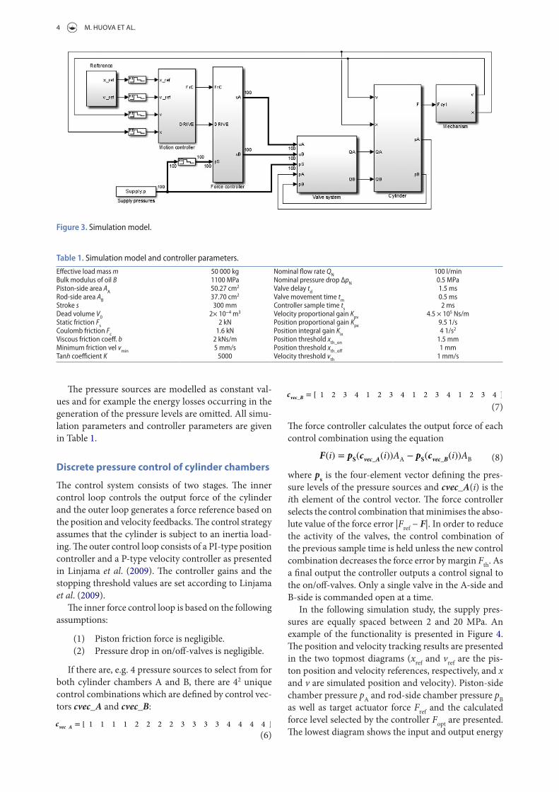
The simulation model is derived based on a medi-um-sized mobile machine boom mock-up previously studied, for example, in Linjama et al. (2009) and pre-sented in the section Experimental Study. Simplifications
are made in order to present the complete model, but the most important characteristics of the load system remain. The simulation model is presented in Figure 3.
The mechanism model is simplified and includes a simple inertia mass of 50000 kg. The external load force is set to zero in the following simulations and the piston friction force is modelled using a Stribeck curve. The zero velocity crossing is smoothed using hyperbolic tan-gent function. The complete mechanism model is
The cylinder pressures pA and pB are modelled as hydrau-lic capacitances
The net flow rate to the cylinder chambers is the sum of flow rates from each supply line. A single flow rate through an on/off-valve is defined using the square root equation the derivative of which is limited to a finite value in the region around zero pressure difference (Ellman and Piché 1996):
where the valve flow coefficient is
and the valve opening xv is a value between zero and one defined by the valve dynamics. The valve dynamics are modelled as a delay and a movement time, during which the valve opening changes with a constant rate.
(1)mx = pAAA − pBAB − tanh(Kx) (1)
×
[FC + (FS − FC)e
−
(x
vmin
)2]− bx (2)
(2)pA = B
∑QA − xAA
xAA + V0
(3)pB = B
∑QB + xAB
(s − x)AB + V0
(4)
QA =
⎧⎪⎨⎪⎩
sign(pS − pA) × xvKv
���pS − pA��, ��pS − pA
�� ≥ ptr
sign(pS − pA) × xvKv
�pS−pA�2√ptr
�3 −
�pS−pA�ptr
�, ��pS − pA
�� < ptr
(5)Kv =QN√ΔpN
Figure 2. Simplified hydraulic diagram of the principle idea.
4 M. HUOVA ET AL.
The force controller calculates the output force of each control combination using the equation
where ps is the four-element vector defining the pres-sure levels of the pressure sources and cvec_A(i) is the ith element of the control vector. The force controller selects the control combination that minimises the abso-lute value of the force error |Fref − F|. In order to reduce the activity of the valves, the control combination of the previous sample time is held unless the new control combination decreases the force error by margin Fth. As a final output the controller outputs a control signal to the on/off-valves. Only a single valve in the A-side and B-side is commanded open at a time.
In the following simulation study, the supply pres-sures are equally spaced between 2 and 20 MPa. An example of the functionality is presented in Figure 4. The position and velocity tracking results are presented in the two topmost diagrams (xref and vref are the pis-ton position and velocity references, respectively, and x and v are simulated position and velocity). Piston-side chamber pressure pA and rod-side chamber pressure pB as well as target actuator force Fref and the calculated force level selected by the controller Fopt are presented. The lowest diagram shows the input and output energy
(7)cvec_B = [ 1 2 3 4 1 2 3 4 1 2 3 4 1 2 3 4 ]
(8)F(i) = pS(cvec_A(i))AA − p
S(cvec_B(i))AB
The pressure sources are modelled as constant val-ues and for example the energy losses occurring in the generation of the pressure levels are omitted. All simu-lation parameters and controller parameters are given in Table 1.
Discrete pressure control of cylinder chambers
The control system consists of two stages. The inner control loop controls the output force of the cylinder and the outer loop generates a force reference based on the position and velocity feedbacks. The control strategy assumes that the cylinder is subject to an inertia load-ing. The outer control loop consists of a PI-type position controller and a P-type velocity controller as presented in Linjama et al. (2009). The controller gains and the stopping threshold values are set according to Linjama et al. (2009).
The inner force control loop is based on the following assumptions:
(1) Piston friction force is negligible.(2) Pressure drop in on/off-valves is negligible.
If there are, e.g. 4 pressure sources to select from for both cylinder chambers A and B, there are 42 unique control combinations which are defined by control vec-tors cvec_A and cvec_B:
(6)cvec_A = [ 1 1 1 1 2 2 2 2 3 3 3 3 4 4 4 4 ]
Figure 3. Simulation model.
Table 1. Simulation model and controller parameters.
effective load mass m 50 000 kg nominal flow rate Qn 100 l/minBulk modulus of oil B 1100 MPa nominal pressure drop Δpn 0.5 MPaPiston-side area Aa 50.27 cm2 Valve delay td 1.5 msrod-side area AB 37.70 cm2 Valve movement time tm 0.5 msStroke s 300 mm Controller sample time ts 2 msdead volume V0 2× 10⁻⁴ m3 Velocity proportional gain Kpv 4.5 × 10⁵ ns/mStatic friction Fs 2 kn Position proportional gain Kpx 9.5 1/sCoulomb friction Fc 1.6 kn Position integral gain Kix 4 1/s2
Viscous friction coeff. b 2 kns/m Position threshold xth_on 1.5 mmMinimum friction vel vmin 5 mm/s Position threshold xth_off 1 mmtanh coefficient K 5000 Velocity threshold vth 1 mm/s

INTERNATIONAL JOURNAL OF FLUID POWER 5
where the first term is the force error and the second term restricts the changing of pressure levels in both cyl-inder chambers. The change of pressure level is weighted by the chamber area and a weight coefficient WdF, which can be adjusted to find a compromise between the switching frequency and control resolution. The switch-ing cost term for A-side is defined as
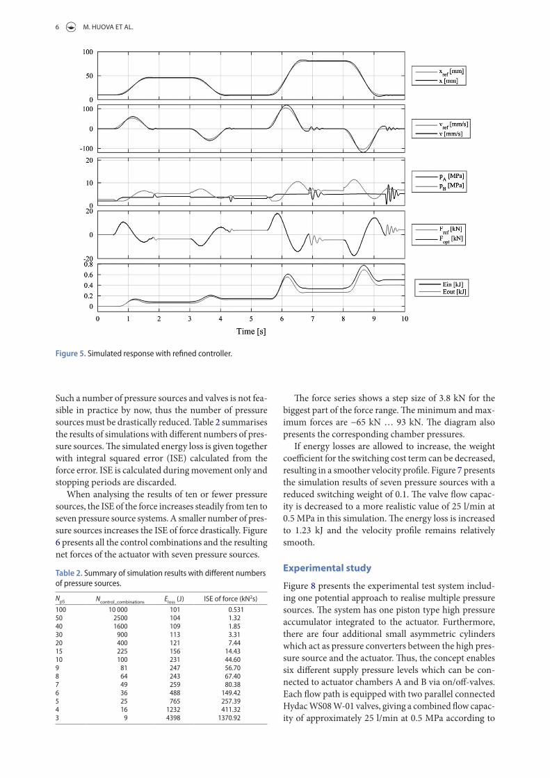
where iopt(k − 1) is the selected optimal control combi-nation of the previous sample time k - 1. The improved controller calculates the cost function for each valve con-trol combination and the control combination with the smallest cost function value is output to the on/off-valves. Figure 5 presents a response with the refined controller.
The weight coefficient WdF is set to 0.15 and the response shows an improved control resolution and energy loss (101 J) which is less than 4 percent of the original value.
Aspects of practical implementation
The previous simulations were carried out with 100 pres-sure sources, which were connected to cylinder cham-bers via 200 on/off-valves. This resulted in 1002 control combinations and a very good force control resolution.
(11)C(i) = ||Fref − F(i)|| +WdF
(||ΔFA(i)|| + ||ΔFB
(i)||)
(12)ΔF
A(i) =
(pS
(cvec_A
(iopt(k − 1)
))− p
S(cvec_A(i))
)AA
of the system. The output energy is the time integral of the output power
which is calculated from the chamber pressures and thus includes the piston friction as part of the output power. The input energy is the time integral of the hydraulic input power taken by the control valves
where pS(i) is the pressure level of the ith pressure source and QA(i) and QB(i) the flow rates of the on/off-valves in the corresponding pressure line.
The example simulation uses 100 pressure sources. The velocity control is smooth even though the threshold value for changing the control combination Fth is set to 2 kN. Despite the very large number of pressure sources, there are significant energy losses (2854 J). The energy is lost on high amplitude and repetitive pressurisation and de-pressurisation of the cylinder chambers, which is due to a simplistic control algorithm.
To avoid excess energy loss, the controller can be improved. The improved force controller uses a cost function to evaluate the control combinations. Instead of selecting the control combination solely based on force error, another optimisation criterion is introduced. The idea is to avoid control combinations which would result in excessive change of the actuator chamber pressures. The cost function is a sum of two terms:
(9)Pout = (pAAA − pBAB) × v
(10)Pin =
NpS∑i=1
pS(i) × (Q
A(i) + Q
B(i))
Figure 4. Initial test simulation of the concept.
6 M. HUOVA ET AL.
The force series shows a step size of 3.8 kN for the biggest part of the force range. The minimum and max-imum forces are −65 kN … 93 kN. The diagram also presents the corresponding chamber pressures.
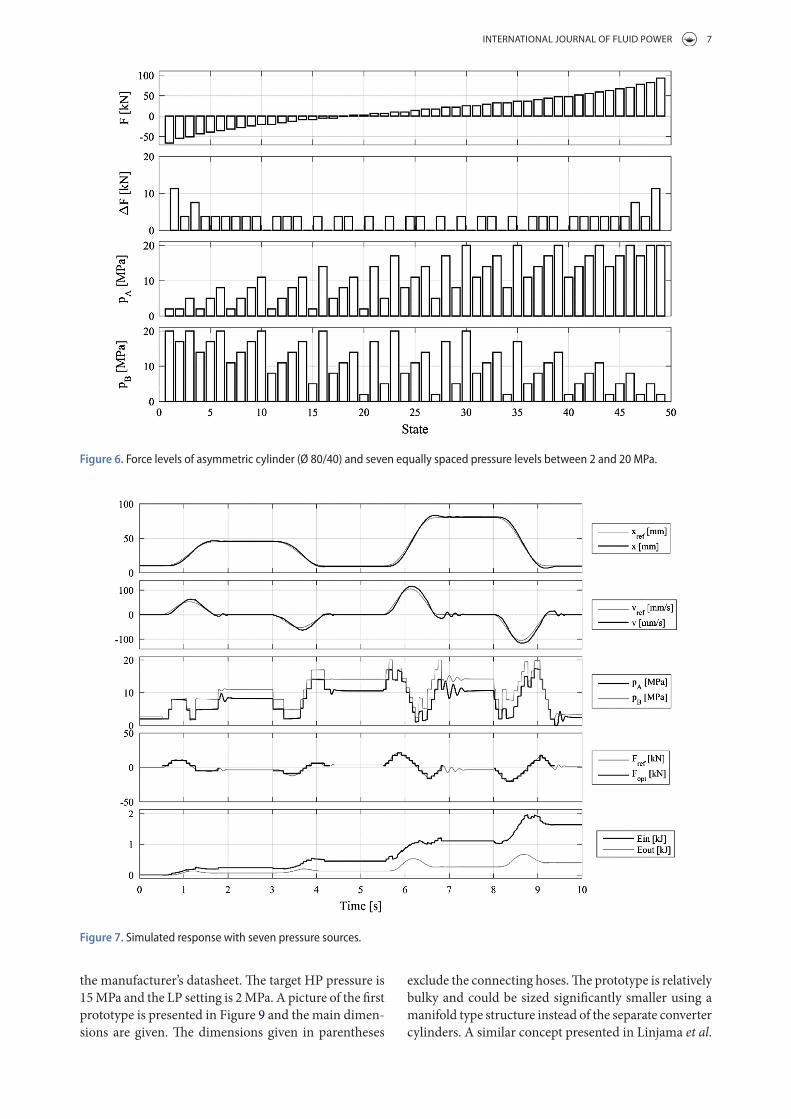
If energy losses are allowed to increase, the weight coefficient for the switching cost term can be decreased, resulting in a smoother velocity profile. Figure 7 presents the simulation results of seven pressure sources with a reduced switching weight of 0.1. The valve flow capac-ity is decreased to a more realistic value of 25 l/min at 0.5 MPa in this simulation. The energy loss is increased to 1.23 kJ and the velocity profile remains relatively smooth.
Experimental study
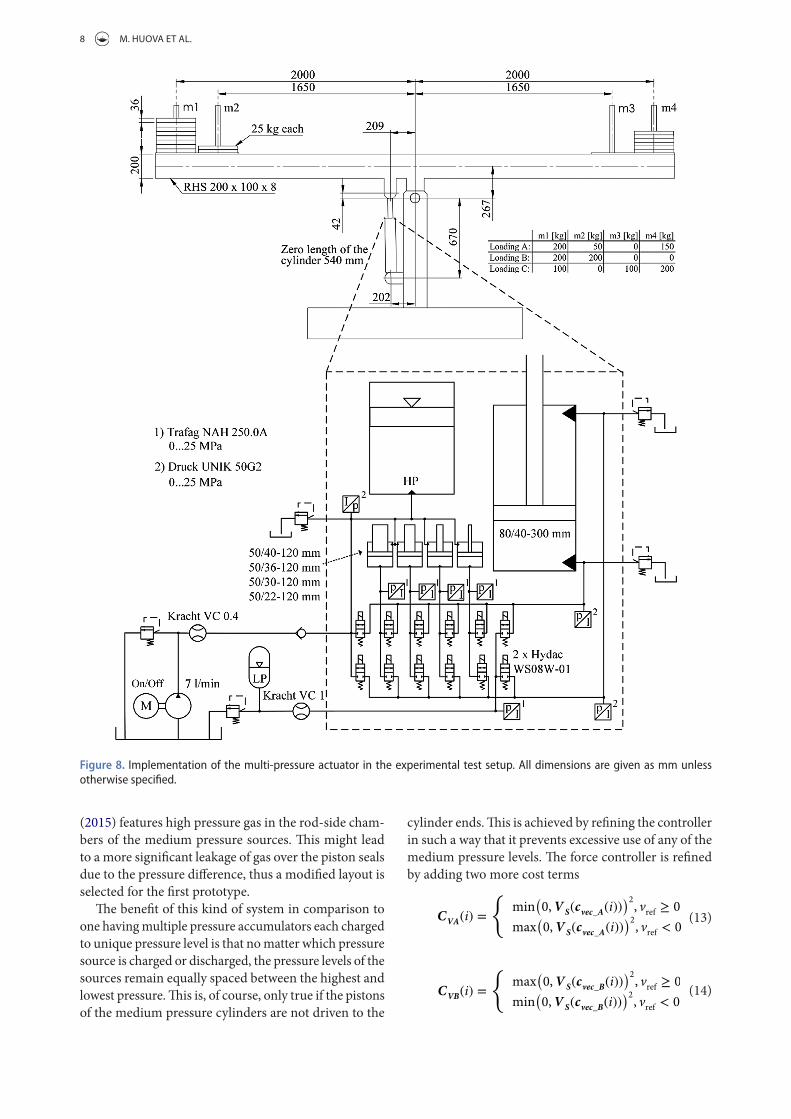
Figure 8 presents the experimental test system includ-ing one potential approach to realise multiple pressure sources. The system has one piston type high pressure accumulator integrated to the actuator. Furthermore, there are four additional small asymmetric cylinders which act as pressure converters between the high pres-sure source and the actuator. Thus, the concept enables six different supply pressure levels which can be con-nected to actuator chambers A and B via on/off-valves. Each flow path is equipped with two parallel connected Hydac WS08 W-01 valves, giving a combined flow capac-ity of approximately 25 l/min at 0.5 MPa according to
Such a number of pressure sources and valves is not fea-sible in practice by now, thus the number of pressure sources must be drastically reduced. Table 2 summarises the results of simulations with different numbers of pres-sure sources. The simulated energy loss is given together with integral squared error (ISE) calculated from the force error. ISE is calculated during movement only and stopping periods are discarded.
When analysing the results of ten or fewer pressure sources, the ISE of the force increases steadily from ten to seven pressure source systems. A smaller number of pres-sure sources increases the ISE of force drastically. Figure 6 presents all the control combinations and the resulting net forces of the actuator with seven pressure sources.
Table 2. Summary of simulation results with different numbers of pressure sources.
NpS Ncontrol_combinations Eloss (J) ISE of force (kN2s)100 10 000 101 0.53150 2500 104 1.3240 1600 109 1.8530 900 113 3.3120 400 121 7.4415 225 156 14.4310 100 231 44.609 81 247 56.708 64 243 67.407 49 259 80.386 36 488 149.425 25 765 257.394 16 1232 411.323 9 4398 1370.92
Figure 5. Simulated response with refined controller.
INTERNATIONAL JOURNAL OF FLUID POWER 7
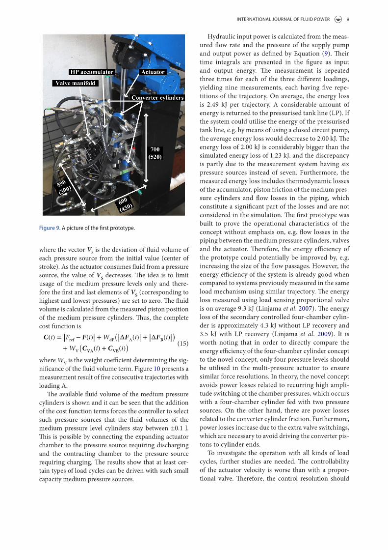
exclude the connecting hoses. The prototype is relatively bulky and could be sized significantly smaller using a manifold type structure instead of the separate converter cylinders. A similar concept presented in Linjama et al.
the manufacturer’s datasheet. The target HP pressure is 15 MPa and the LP setting is 2 MPa. A picture of the first prototype is presented in Figure 9 and the main dimen-sions are given. The dimensions given in parentheses
Figure 6. force levels of asymmetric cylinder (Ø 80/40) and seven equally spaced pressure levels between 2 and 20 MPa.
Figure 7. Simulated response with seven pressure sources.
8 M. HUOVA ET AL.
cylinder ends. This is achieved by refining the controller in such a way that it prevents excessive use of any of the medium pressure levels. The force controller is refined by adding two more cost terms
(13)CVA(i) =
{min
(0,VS(cvec_A(i))
)2, vref ≥ 0
max(0,VS(cvec_A(i))
)2, vref < 0
(14)CVB(i) =
{max
(0,VS(cvec_B(i))
)2, vref ≥ 0
min(0,VS(cvec_B(i))
)2, vref < 0
(2015) features high pressure gas in the rod-side cham-bers of the medium pressure sources. This might lead to a more significant leakage of gas over the piston seals due to the pressure difference, thus a modified layout is selected for the first prototype.
The benefit of this kind of system in comparison to one having multiple pressure accumulators each charged to unique pressure level is that no matter which pressure source is charged or discharged, the pressure levels of the sources remain equally spaced between the highest and lowest pressure. This is, of course, only true if the pistons of the medium pressure cylinders are not driven to the
Figure 8. Implementation of the multi-pressure actuator in the experimental test setup. all dimensions are given as mm unless otherwise specified.
INTERNATIONAL JOURNAL OF FLUID POWER 9
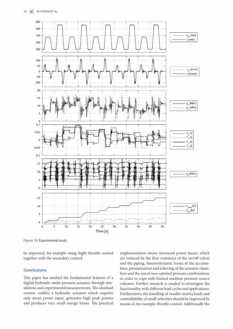
Hydraulic input power is calculated from the meas-ured flow rate and the pressure of the supply pump and output power as defined by Equation (9). Their time integrals are presented in the figure as input and output energy. The measurement is repeated three times for each of the three different loadings, yielding nine measurements, each having five repe-titions of the trajectory. On average, the energy loss is 2.49 kJ per trajectory. A considerable amount of energy is returned to the pressurised tank line (LP). If the system could utilise the energy of the pressurised tank line, e.g. by means of using a closed circuit pump, the average energy loss would decrease to 2.00 kJ. The energy loss of 2.00 kJ is considerably bigger than the simulated energy loss of 1.23 kJ, and the discrepancy is partly due to the measurement system having six pressure sources instead of seven. Furthermore, the measured energy loss includes thermodynamic losses of the accumulator, piston friction of the medium pres-sure cylinders and flow losses in the piping, which constitute a significant part of the losses and are not considered in the simulation. The first prototype was built to prove the operational characteristics of the concept without emphasis on, e.g. flow losses in the piping between the medium pressure cylinders, valves and the actuator. Therefore, the energy efficiency of the prototype could potentially be improved by, e.g. increasing the size of the flow passages. However, the energy efficiency of the system is already good when compared to systems previously measured in the same load mechanism using similar trajectory. The energy loss measured using load sensing proportional valve is on average 9.3 kJ (Linjama et al. 2007). The energy loss of the secondary controlled four-chamber cylin-der is approximately 4.3 kJ without LP recovery and 3.5 kJ with LP recovery (Linjama et al. 2009). It is worth noting that in order to directly compare the energy efficiency of the four-chamber cylinder concept to the novel concept, only four pressure levels should be utilised in the multi-pressure actuator to ensure similar force resolutions. In theory, the novel concept avoids power losses related to recurring high ampli-tude switching of the chamber pressures, which occurs with a four-chamber cylinder fed with two pressure sources. On the other hand, there are power losses related to the converter cylinder friction. Furthermore, power losses increase due to the extra valve switchings, which are necessary to avoid driving the converter pis-tons to cylinder ends.
To investigate the operation with all kinds of load cycles, further studies are needed. The controllability of the actuator velocity is worse than with a propor-tional valve. Therefore, the control resolution should
where the vector VS is the deviation of fluid volume of each pressure source from the initial value (center of stroke). As the actuator consumes fluid from a pressure source, the value of VS decreases. The idea is to limit usage of the medium pressure levels only and there-fore the first and last elements of VS (corresponding to highest and lowest pressures) are set to zero. The fluid volume is calculated from the measured piston position of the medium pressure cylinders. Thus, the complete cost function is
where WV is the weight coefficient determining the sig-nificance of the fluid volume term. Figure 10 presents a measurement result of five consecutive trajectories with loading A.
The available fluid volume of the medium pressure cylinders is shown and it can be seen that the addition of the cost function terms forces the controller to select such pressure sources that the fluid volumes of the medium pressure level cylinders stay between ±0.1 l. This is possible by connecting the expanding actuator chamber to the pressure source requiring discharging and the contracting chamber to the pressure source requiring charging. The results show that at least cer-tain types of load cycles can be driven with such small capacity medium pressure sources.
(15)C(i) = ||Fref − F(i)|| +WdF
(||ΔFA(i)|| + ||ΔFB
(i)||)
+WV
(C
VA(i) + C
VB(i))
Figure 9. a picture of the first prototype.
10 M. HUOVA ET AL.
implementation shows increased power losses, which are induced by the flow resistance of the on/off-valves and the piping, thermodynamic losses of the accumu-lator, pressurisation and relieving of the actuator cham-bers and the use of non-optimal pressure combinations in order to cope with limited medium pressure source volumes. Further research is needed to investigate the functionality with different load cycles and applications. Furthermore, the handling of smaller inertia loads and controllability of small velocities should be improved by means of, for example, throttle control. Additionally the
be improved, for example using slight throttle control together with the secondary control.
Conclusions
This paper has studied the fundamental features of a digital hydraulic multi-pressure actuator through sim-ulations and experimental measurements. The idealised version enables a hydraulic actuator which requires only mean power input, generates high peak powers and produces very small energy losses. The practical
Figure 10. experimental result.

INTERNATIONAL JOURNAL OF FLUID POWER 11
Tapio Lantela is a doctoral student at Aalto University School of Engineering. He received his MSc from Aalto University in 2012. The topic of his master’s thesis was developing a pilot-operated miniature on/off valve and the topic of his doctoral studies is to create a digital valve system consisting of a number of these miniature valves. The areas on interest include fast switching valves,
electromagnetic actuators and valve electronics.
Matti Pietola received his DSc in 1989 at Helsinki University of Technology (later Aalto University) and has been a professor of Mechatronics (Fluid Power Systems) there since 1997.
ORCIDMikko Huova http://orcid.org/0000-0001-6384-7688Matti Linjama http://orcid.org/0000-0002-4861-5624Kalevi Huhtala http://orcid.org/0000-0003-4055-0392
ReferencesAchten, P. and van den Brink, T., 2012. A hydraulic
transformer with a swash block control around three axis of rotation. 8th International Fluid Power Conference, 26–28 March, Dresden, Germany.
Anon, 2015. Incova Technologies [online]. Available from: http://www.incova.com/ [Accessed 30 July 2015].
Belan, C., et al., 2015. Digital secondary control architecture for aircraft application. The Seventh Workshop on Digital Fluid Power, 26–27 February 2015, Linz, Austria.
Bishop, E., 2009. Digital hydraulic transformer – approaching theoretical perfection in hydraulic drive efficiency. The 11th Scandinavian International Conference on Fluid Power, 2–4 June, Linköping, Sweden.
Bishop, E., 2010. Linearization of quantized digital hydraulic transformer output. The Third Workshop on Digital Fluid Power, 13–14 October, Tampere, Finland.
Ellman, A. and Piché, R., 1996. A modified orifice flow formula for numerical simulation of fluid power systems. Journal of Dynamic Systems, Measurement, and Control, 121 (4), 721–724.
Eriksson, B. and Palmberg, J.-O., 2011. Individual metering fluid power systems: challenges and opportunities. Proceedings of the Institution of Mechanical Engineers, Part I: Journal of Systems and Control Engineering, 225 (2), 196–211. doi: 10.1243/09596518JSCE1111
Hansen, A., Pedersen, H., and Bech, M., 2015. Avoidance of transmission line pressure oscillations in discrete hydraulic systems – by shaping of valve opening characteristics. The Seventh Workshop on Digital Fluid Power, 26–27 February 2015, Linz, Austria.
Heemskerk, E., Bonefeld, R., and Buschmann, H., 2015. Control of a semi-binary hydraulic four-chamber cylinder. The 14th Scandinavian International Conference on Fluid Power, 20–22 May, Tampere, Finland.
energy losses could be potentially decreased further with a refined system design including, for example, larger flow passages. However, already the first measurement results of the prototype show that highly efficient con-trol of inertia loads is possible with a practical number of pressure sources: when compared to the measured results with a load sensing proportional valve, the losses are reduced by approximately 73%.
Disclosure statementNo potential conflict of interest was reported by the authors.
FundingThis work was supported by the Academy of Finland [grant number 278464].
Notes on contributors
Mikko Huova received a DSc degree at Tampere University of Technology, Finland, in 2015. The topic of his thesis is related to energy-efficient digital hydraulic systems and he is continuing the work on this subject as a postdoctoral researcher at TUT. The areas of interest include control design, modelling, simulation and energy-efficient systems.
Arttu Aalto received his MSc from Tampere University of Technology, Finland in 2016. The topic of his master’s thesis is related to energy-efficient digital hydraulic multi-pres-sure actuator.
Matti Linjama obtained a D Tech degree at Tampere University of Technology, Finland in 1998. Currently, he is an adjunct profes-sor at the Laboratory of Automation and Hydraulic Engineering (AUT). He started the study of digital hydraulics in 2000 and has focused on the topic since then. Currently, he is leader of the digital hydraulics research group in AUT and his professional interests
include the study of hydraulic systems with high energy effi-ciency. He is also teaching digital hydraulics at AUT.
Kalevi Huhtala received his D Tech degree from Tampere University of Technology (Finland) in 1996. He is currently working as a professor in the Laboratory of Automation and Hydraulic Engineering (AUT) at the same university. He is also the head of labo-ratory. His primary research fields are intel-ligent mobile machines and diesel engine hydraulics.
12 M. HUOVA ET AL.
Scandinavian International Conference on Fluid Power, 20–22 May, Tampere, Finland.
Pan, M., et al., 2014. Experimental investigation of a switched inertance hydraulic system. ASME/Bath Symposium on Fluid Power and Motion Control (FPMC14). Bath, UK.
Scheidl, R., et al., 2008. The hydraulic buck converter – concept and experimental results. 6th International Fluid Power Conference, 1–2 April, Dresden, Germany, Vol. 2, pp. 501–513.
Sprengler, M. and Ivantysynova, M., 2012. Coupling displacement controlled actuation with power split transmissions in hydraulic hybrid systems for off-highway vehicles actuation with power split transmissions in hydraulic hybrid systems for off-highway vehicles. ASME/Bath Symposium on Fluid Power and Motion Control (FPMC12). Bath, UK.
Vukovic, M., Leifeld, R., and Murrenhoff, H., 2016. STEAM – a hydraulic hybrid architecture for excavators. 10th International Fluid Power Conference (10. IFK), 8–10 March, Dresden, Germany.
Williamson, C., Zimmerman, J. and Ivantysynova, M., 2008. Efficiency study of an excavator hydraulic system based on displacement-controlled actuators. ASME/Bath Workshop on Fluid Power and Motion Control (FPMC08), Bath, UK.
Heikkilä, M. and Linjama, M., 2013. Displacement control of a mobile crane using a digital hydraulic power management system. Mechatronics, 23 (4), 452–461.
Huova, M., 2015. Energy efficient digital hydraulic valve control. Thesis (PhD). Tampere University of Technology, Tampere, Finland.
Huova, M., Laamanen, A., and Linjama, M., 2010. Energy efficiency of three-chamber cylinder with digital valve system. International Journal of Fluid Power, 11 (3), 15–22.
Karvonen, M., et al., 2014. Analysis by simulation of different control algorithms of a digital hydraulic two-actuator system. International Journal of Fluid Power, 15 (1), 33–44.
Kogler, H. and Scheidl, R., 2012. The hydraulic buck converter exploiting the load capacitance. 8th International Fluid Power Conference, 26–28 March, Dresden, Germany.
Linjama, M., et al., 2007. Design and implementation of energy saving digital hydraulic control system. The Tenth Scandinavian International Conference on Fluid Power (SICFP’07), Tampere, Finland.
Linjama, M., et al., 2009. Secondary controlled multi-chamber hydraulic cylinder. The 11th Scandinavian International Conference on Fluid Power, 2–4 June 2009, Linköping, Sweden.
Linjama, M., et al., 2015. Hydraulic hybrid actuator: theoretical aspects and solution alternatives. The 14th