Hardware for Sliding Gates - Spinea Oy · 2016-06-22 · Hardware for Sliding Gates Rail Stop and...
96
Hardware for Sliding Gates Catalogue: TEH_06
Transcript of Hardware for Sliding Gates - Spinea Oy · 2016-06-22 · Hardware for Sliding Gates Rail Stop and...

Hardware for Sliding Gates
Catalogue: TEH_06

2TEH_06/07.2014
Contents
General Information
Fields of application Page 3
Hardware for Sliding Gates
General Information, HELM 100 - HELM 700 Page 4
Certification Page 5
Technical Information Page 6
Applications Page 14
Installation Cross-sections and Installation Dimensions Page 22
Single Parts Page 26
Suspended Rolls Page 46
Special Rollers up to 8000 kg door weight Page 47
Special Applications
Round the Corner Sliding Door Hardware Page 50
Folding Door Hardware and Concertina Door Hardware Page 60
Parallel Sliding-Stacking Hardware Page 76
Hardware for Flush Sliding Installations Page 84
Accessories
Pull Handles and Flush Handles Page 92
Hardware for Sliding Gates

3
Gen
eral
Info
rmat
ion
TEH_06/07.2014
General Information Hardware for Sliding Gates
HELM sliding hardware is very versatile.
High-quality materials and more than 75 years of experience in developing and manufacturing of sliding hardware guar-antee the long service life of the HELM hardware. With a wide range and manifold possibilities to manufacture individual solutions HELM stands, above all, for a very versatile range of applications.
The most common applications of the HELM sliding hardware can be found in the field of straight sliding gates. With the track series HELM 100 up to HELM 700 we offer a comprehensive range up to 2000 kg door weight. Moreover, for higher door weights special rollers up to 8000 kg door weight are manufactured.
In addition to the classic, straight sliding hardware we present also many specialapplications for sliding doors and gates, as well as mobile partition solutions in this catalogue:
- round the corner sliding door hardware- folding hardware- concertina door hardware- parallel sliding and stacking hardware- hardware for flush sliding installations
For these special solutions you will find the respective schematic depictions of the installation types and further informa-tion regarding the distinctive features. Furthermore, we offer you the opportunity to use our consulting service easily and quickly with the help of the respective enquiry forms.

4TEH_06/07.2014
Hardware for Sliding GatesGeneral Information
As a matter of course the HELM hardware for straight sliding gates complies with the requirements of DIN 1527:1998 and are also tested for fire doors (profile 400 to 700) according to DIN 18200 and 4102-18.
Particularly the 100,000 cycles test with the double-pair trolley hangers of the -91 series stands for the long service life of the HELM hardware up to 2000 kg door weight. High-quality ball bearings make the excellent running properties also in higher weight classes possible.
But also achieving the corrosion resistance according to class 3 (according to EN 1670: class 1-4) is crucial for outdoor use. For special requirements in this field the track series 100 to 500 with the relevant accessories are also manufactured in stainless steel.
On the following Pages you will find all the necessary information for choosing the right track series (page 6 and 7) and regarding the possible applications with the respective set combinations (pages 14 to 21).
Straight Sliding Hardware

5
Gen
eral
Info
rmat
ion
TEH_06/07.2014
Hardware for Sliding Gates
Certification according to DIN EN 1527:1998
HELM tracks 100 to 700 have been tested in combination with double-pair trolley hangers according to DIN 1527: 1998. This standard makes a simple and quick comparison of different products possible according to the following criteria:
Criteria of DIN EN 1527:
Test results:
Service life time: Classes: 1 = 2,500 cycles, 2 = 5,000 cycles, 3 = 10,000, 4 = 25,000 cycles, 5 = 50,000 cycles, 6 (highest class) = 100,000 cycles Door weight:
Classes: 1 = up to 50 kg, 2 = 50-100 kg, 3 = 100-330 kg, 4 = more than 330 kg
Corrosion resistance:
0 (no requirement) - 4 (highest class) Type of door:
1 = sliding door, 2 = double folding door, 3 = multi-leaf folding door
Initial friction:
Door weight up to 50 kg up to 100 kg up to 330 kg more than 330 kg
Class 1 50 N 80 N 100 N 5 % of door weight
Class 2 40 N 60 N 5 % of door weight 4 % of door weight
Class 3 30 N 40 N 4 % of door weight 3 % of door weight
Certification
HELM trackin combination with trolley hanger
Max. tested bearing load
Service life time Door weight Corrosion resistance
Type of door Initial friction
100 191, 191S, 110, 112 90 kg 6 2 3 1 3
300 391, 391 S, 391EL, 392 170 kg 6 3 3 1 3
400 491, 491S, 491 EL, 412 300 kg 6 3 3 1 3
500 510, 512, 591, 591S, 591EL 600 kg 6 4 3 1 3
600 610, 691, 691S, 691EL 1200 kg 6 4 3 1 3
700 791, 791S, 791EL 2000 kg 6 4 3 1 3
6TEH_06/07.2014
Hardware for Sliding Gates
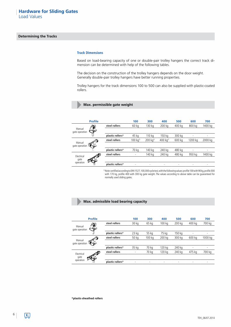
Track Dimensions
Based on load-bearing capacity of one or double-pair trolley hangers the correct track di-mension can be determined with help of the following tables.
The decision on the construction of the trolley hangers depends on the door weight. Generally double-pair trolley hangers have better running properties.
Trolley hangers for the track dimensions 100 to 500 can also be supplied with plastic-coated rollers.
Load Values
Determining the Tracks
Profile 100 300 400 500 600 700
steel rollers 60 kg 130 kg 200 kg 400 kg 800 kg 1400 kg
plastic rollers* 45 kg 110 kg 150 kg 300 kg - -steel rollers 100 kg1) 200 kg1) 400 kg1) 600 kg 1200 kg 2000 kg
plastic rollers* 70 kg 140 kg 240 kg 480 kg - -steel rollers - 140 kg 240 kg 480 kg 950 kg 1400 kg
plastic rollers* - - - - - -
Max. permissible gate weight
1) Note: certified according to DIN 1527, 100,000 cycle test, with the following values: profile 100 with 90 kg, profile 300 with 170 kg, profile 400 with 300 kg gate weight. The values according to above table can be guaranteed for normally used sliding gates.
Manual gate operation
Manual gate operation
Electrical gate
operation
Profile 100 300 400 500 600 700
steel rollers 30 kg 65 kg 100 kg 200 kg 400 kg 700 kg
plastic rollers* 23 kg 55 kg 75 kg 150 kg - -steel rollers 50 kg 100 kg 200 kg 300 kg 600 kg 1000 kg
plastic rollers* 35 kg 70 kg 120 kg 240 kg - -steel rollers - 70 kg 120 kg 240 kg 475 kg 700 kg
plastic rollers* - - - - - -
Max. admissible load bearing capacity
Manual gate operation
Manual gate operation
Electrical gate
operation
*plastic-sheathed rollers

7
Tech
nic
al in
form
atio
n
TEH_06/07.2014
Hardware for Sliding Gates
HELM Tracks
The HELM tracks are available in steel blank or zinc-plated, in stock lengths of max. approx. 6000 mm or in fixed lengths. The profiles HELM 100, 300, 400 and 500 are also made of stainless steel.
Fixing brackets are to be planned with a spacing of 750 mm. The track hanging can be adjusted to the structural conditions according to the specifications from Page 22.
Profile size 100 300 400 500 600 700h (mm) 28 35 43.5 60 75 110b (mm) 30 40 48.5 65 80 90s (mm) 1.75 2.75 3.2 3.6 4.5 6.5
Profile size 100 300 400 500h (mm) 28 35 43.5 59b (mm) 30 40 48.5 64s (mm) 1.6 3 3.1 3.5
Load Values
Track profile in steel
Track profile in stainless steel
Track Profiles
Hanging spacings
8TEH_06/07.2014
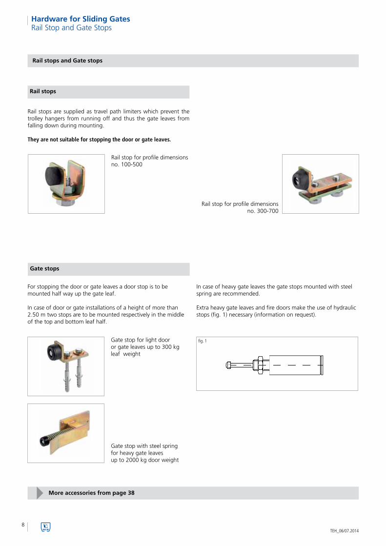
Hardware for Sliding GatesRail Stop and Gate Stops
Rail stops and Gate stops
Rail stops are supplied as travel path limiters which prevent the trolley hangers from running off and thus the gate leaves from falling down during mounting.
They are not suitable for stopping the door or gate leaves.
Rail stop for profile dimensions no. 100-500
Rail stop for profile dimensions no. 300-700
For stopping the door or gate leaves a door stop is to be mounted half way up the gate leaf.
In case of door or gate installations of a height of more than 2.50 m two stops are to be mounted respectively in the middle of the top and bottom leaf half.
Gate stops
Gate stop with steel spring for heavy gate leaves up to 2000 kg door weight
fig. 1
Rail stops
Gate stop for light door or gate leaves up to 300 kg leaf weight
In case of heavy gate leaves the gate stops mounted with steel spring are recommended. Extra heavy gate leaves and fire doors make the use of hydraulic stops (fig. 1) necessary (information on request).
More accessories from page 38

9
Tech
nic
al in
form
atio
n
TEH_06/07.2014
Hardware for Sliding Gates
Rollers and Trolley Hangers
The decision on the construction of the trolley hangers depends on the door weight (see Page 6). Due to the better guiding in the profile track double-pair trolley hangers with pendulum hinge (fig. 2), than the one-pair construction (fig. 1), ensure significantly better running properties.
Trolley hangers for the profile dimensions 100 to 500 are also available with rollers including plastic outer ring for low-noise operation. In this case the load bearing capacity is decreased by approx. 15% to 25% (see Page 6).
Series -90one-pair trolley hanger with pendulum hinge of plastic or steel, height-adjustable
Series -91double-pair trolley hanger with pendulum hinge of
plastic or steel, height-adjustable
Series -92double-pair trolley hanger with pendulum hinge of plastic or steel and with counter-pressure roller for sliding leaves with top-hung leaves, height-adjustable
The rollers are designed for the temperature range of -20°C up to +115° C.
hardened roller for trolley hangers in the profile sizes no. 100 - 700
plastic-sheathed rollers. This type is available for trolley hangers in the
profile sizes no. 100 - 500.
1. "cowshed" grease T = -10°C up to +140°C2. high-temperature grease T = -30°C up to +260°C3. deep-freeze grease T = -40°C up to 140°C
Rollers Special lubrications on request
Trolley Hangers (two trolley hangers per leaf are used only)
Series -91 ELdouble-pair trolley hanger with pendulum hinge of
plastic or steel, with 2 transverse rollers for electrically operated gates, height-adjustable
double-pair special trolley hanger - for load-bearing capacity up to 1500 and 4000 kg
- for gate weights 3000 and 8000 kg
Series -91/85double-pair trolley hanger with pendulum hinge of steel for fire-protection sliding gates, height-adjustable
More accessories from page 32
fig. 1 fig. 2

10TEH_06/07.2014
Hardware for Sliding GatesHanging Material for Leaves
Hanging Material for Leaves (Flanges and Angle Brackets)
Flanges (fig. 2 and fig. 3) for hanging the sliding leaves that are wider (B) than high (H). Positioning at the out-er edges with a spacing of 1/6 of the total width of the leaf guarantees a suspension in the gravity centre and a smooth-running, trouble-free operation of the hard-ware and the gate.
Independent of the leaf width only two trolley hangers per leaf are used.
Hanging material for leaves – flange -93 and -93 S
Hanging material for leaves – flange -94 and -96 S
Support bracket (fig. 6) or flange (fig. 5) for suspen-ding the sliding gates that are higher than wide.
Running track gets longer - a) due to projection of the rolls b) due to mounting of the track stops
Flange of the series -93 S (fig. 3) for welding on
steel leaves
B
1/6 B 1/6 B
flange
Flange of the series -93 (fig. 2) for bolting down with timber leaves
angle bracket for timber leaves
Flange for welding on
Angle bracket of the series -94 (fig. 6) for bolting down with timber leaves
Flange of the series -96 S (fig. 5) for welding on steel leaves
fig. 3fig. 2
fig. 1
fig. 5
fig. 6fig. 4
Angle bracket or flange for hanging the leaves.
Use e. g. for double doors.
Hanging material for leaves – flange -95 and -93 S
angle bracket
flangeAngle bracket of the series -95 (fig. 9) for bolting down with timber leaves
Flange of the series -93 S (fig. 8) for welding on steel leaves
fig. 8
fig. 9fig. 7
More accessories from page 36
11
Tech
nic
al in
form
atio
n
TEH_06/07.2014
Hardware for Sliding Gates
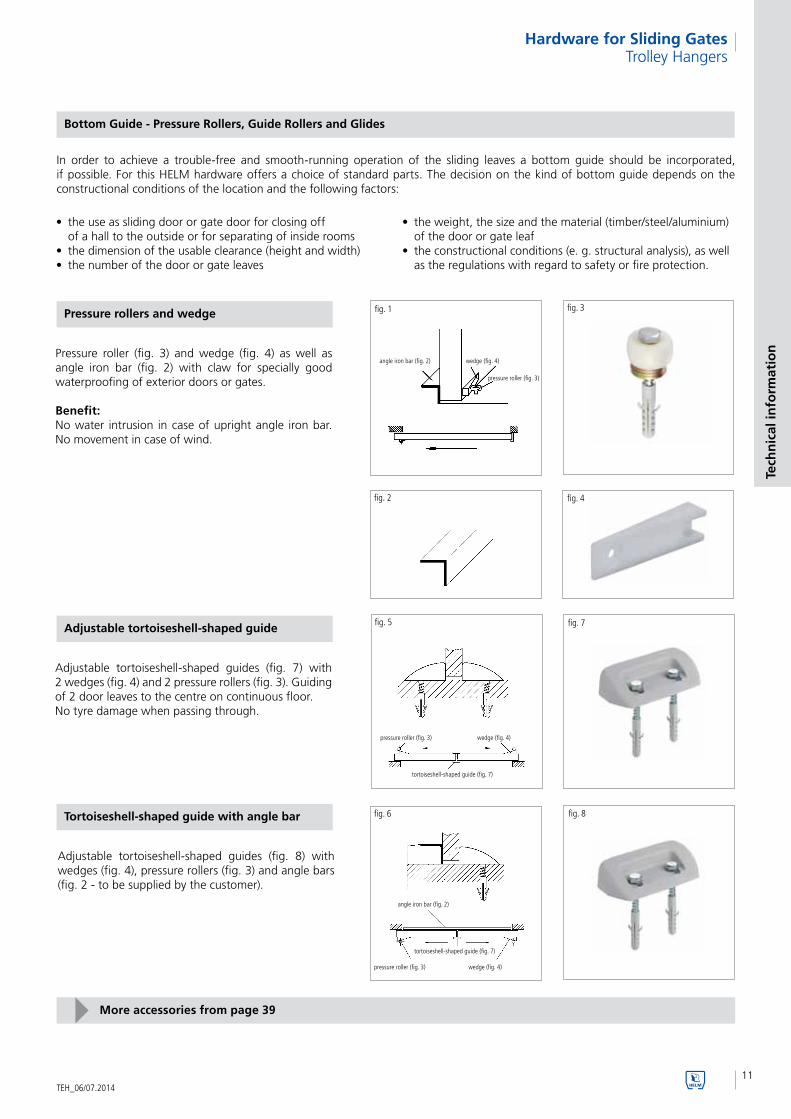
In order to achieve a trouble-free and smooth-running operation of the sliding leaves a bottom guide should be incorporated, if possible. For this HELM hardware offers a choice of standard parts. The decision on the kind of bottom guide depends on the constructional conditions of the location and the following factors:
Bottom Guide - Pressure Rollers, Guide Rollers and Glides
• theuseasslidingdoororgatedoorforclosingoff of a hall to the outside or for separating of inside rooms• thedimensionoftheusableclearance(heightandwidth)• thenumberofthedoororgateleaves
Pressure rollers and wedge
Pressure roller (fig. 3) and wedge (fig. 4) as well as angle iron bar (fig. 2) with claw for specially good waterproofing of exterior doors or gates.
Benefit:No water intrusion in case of upright angle iron bar. No movement in case of wind.
fig. 1 fig. 3
fig. 2 fig. 4
• theweight,thesizeandthematerial(timber/steel/aluminium) of the door or gate leaf• theconstructionalconditions(e.g.structuralanalysis),aswell as the regulations with regard to safety or fire protection.
Adjustable tortoiseshell-shaped guide
Adjustable tortoiseshell-shaped guides (fig. 7) with 2 wedges (fig. 4) and 2 pressure rollers (fig. 3). Guiding of 2 door leaves to the centre on continuous floor. No tyre damage when passing through.
fig. 5 fig. 7
Tortoiseshell-shaped guide with angle bar
Adjustable tortoiseshell-shaped guides (fig. 8) with wedges (fig. 4), pressure rollers (fig. 3) and angle bars (fig. 2 - to be supplied by the customer).
fig. 6 fig. 8
angle iron bar (fig. 2) wedge (fig. 4)
pressure roller (fig. 3)
More accessories from page 39
pressure roller (fig. 3) wedge (fig. 4)
tortoiseshell-shaped guide (fig. 7)
angle iron bar (fig. 2)
tortoiseshell-shaped guide (fig. 7)
pressure roller (fig. 3) wedge (fig. 4)
Trolley Hangers
12TEH_06/07.2014
Hardware for Sliding GatesBottom Guides
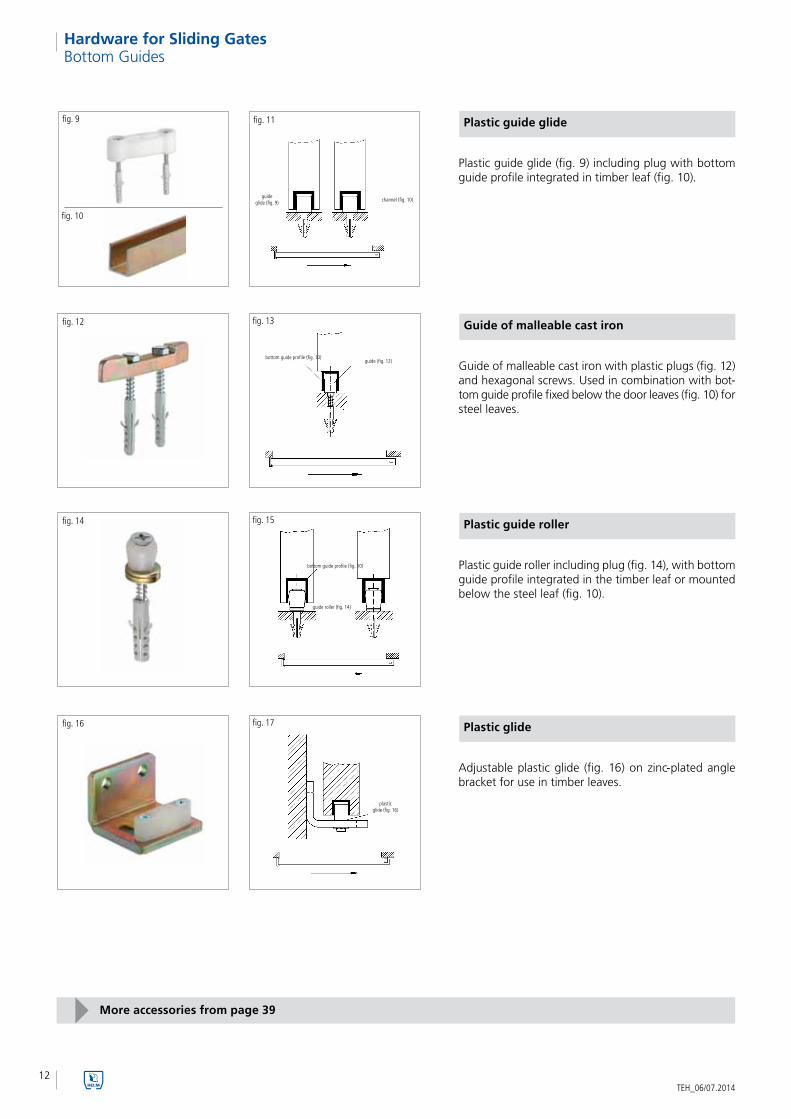
Plastic guide glide
Plastic guide glide (fig. 9) including plug with bottom guide profile integrated in timber leaf (fig. 10).
fig. 11fig. 9
fig. 10
Guide of malleable cast iron
Guide of malleable cast iron with plastic plugs (fig. 12) and hexagonal screws. Used in combination with bot-tom guide profile fixed below the door leaves (fig. 10) for steel leaves.
fig. 13fig. 12
Plastic guide roller
Plastic guide roller including plug (fig. 14), with bottom guide profile integrated in the timber leaf or mounted below the steel leaf (fig. 10).
fig. 15fig. 14
Plastic glide
Adjustable plastic glide (fig. 16) on zinc-plated angle bracket for use in timber leaves.
fig. 17fig. 16
More accessories from page 39
guideglide (fig. 9) channel (fig. 10)
bottom guide profile (fig. 10)guide (fig. 12)
guide roller (fig. 14)
bottom guide profile (fig. 10)
plasticglide (fig. 16)

13
Tech
nic
al in
form
atio
n
TEH_06/07.2014
Hardware for Sliding GatesBottom Guides
Adjustable guide roller
Adjustable guide roller (plastic or brass) (fig. 19) on zinc-plated angle bracket and plastic guide peg. For guiding fixed on the side, staggered door leaves (fig. 18).
fig. 18 fig. 19
fig. 23 fig. 24 fig. 24.1Guide roller for steel leaves
Guide roller (fig. 24 and fig. 24.1) for steel leaves with screw or rivet or welded joint. Zinc-plated with plastic or brass roller. Used in combination with bottom guide profile.
Guide roller angle bracket and flange fixing
Guide roller with angle bracket (fig. 21) and flange fixing (fig. 22). Suitable in combination with bottom guide profile for timber leaves.
fig. 20 fig. 21
fig. 22
Guide rollers with plate
Guide roller on plate (fig. 26) for bolting down or with plastic plug for boring in.
Double guide roller on plate (fig. 28) for boring in. Through inclination of the base plate is a continuous adjustment to the leaf thickness possible.
fig. 25 fig. 27
fig. 26 fig. 28
More accessories from page 39
guide glideno. 216/ no. 316
guide glideno. 216/no. 316
Adjustableguide roller
(fig. 19)
Adjustable guide roller (fig. 19)
guide roller (fig. 21)angle bracket fixing
guide roller (fig. 22)flange fixing
guide roller (fig. 24.1)screw joint
guide roller (fig. 24)rivet joint
pressure roller (fig. 28)
double guide roller (fig. 26) on plate
14
1
2
3
5
4
6
8
7
12345678
TEH_06/07.2014
Hardware for Sliding GatesApplications
1every 750 mm 2quantity depends on the track length
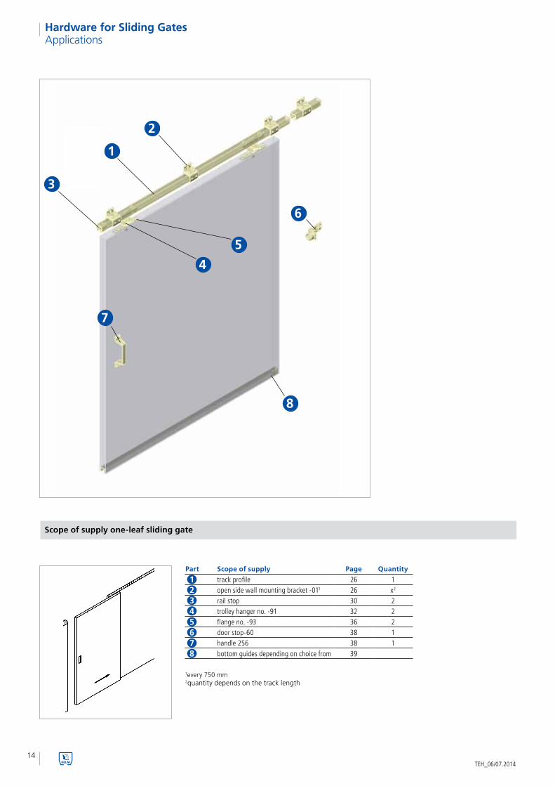
Part Scope of supply Page Quantity
track profile 26 1open side wall mounting bracket -011 26 x2
rail stop 30 2trolley hanger no. -91 32 2flange no. -93 36 2door stop-60 38 1handle 256 38 1bottom guides depending on choice from 39
Scope of supply one-leaf sliding gate

15
1
2
4
56
8
7
3
12345678
Gen
eral
Info
rmat
ion
TEH_06/07.2014
Hardware for Sliding GatesApplications
Scope of supply double leaf sliding gate
Part Scope of supply Page Quantity
track profile 26 1open side wall mounting bracket -011 26 x2
rail stop 30 4trolley hanger -91 32 4flange -93 36 4door stop-60 38 2handle 256 38 2bottom guides depending on choice from 39
1every 750 mm 2quantity depends on the track length

16
1
2
54
6
8
7
3
12345678
TEH_06/07.2014
Hardware for Sliding Gates
1every 750 mm 2number depends on the track length
Part Scope of supply Page Quantity
track profile 26 2double joint ceiling bracket -02 D1 27 x2
rail stop 30 4trolley hanger -91 32 4flange -93 36 4guide roller -58 DÜ 42 2bottom guide profile -40 44 2flush handle 92 4
Scope of supply double leaf sliding gate (running in the reveal)
Applications

17
12
3
9
5
8
7
4
6
123456789
Gen
eral
Info
rmat
ion
TEH_06/07.2014
Hardware for Sliding Gates
Scope of supply double leaf sliding gate
Part Scope of supply Page Quantity
track profile 26 2angle bracket -04 WD1 29 x2
height-adjustable bracket -041 28 x2
rail stop 30 4trolley hanger -91 32 4flange -93 36 4bottom guide profile -40 44 2guide roller -58 DÜ 42 1flush handle 92 2
1every 750 mm 2quantity depends on the track length
Applications
123456789
18
123456789
10
12
4
5
6
7
9
310
8
TEH_06/07.2014
Hardware for Sliding GatesApplications
1every 750 mm 2number depends on the track length
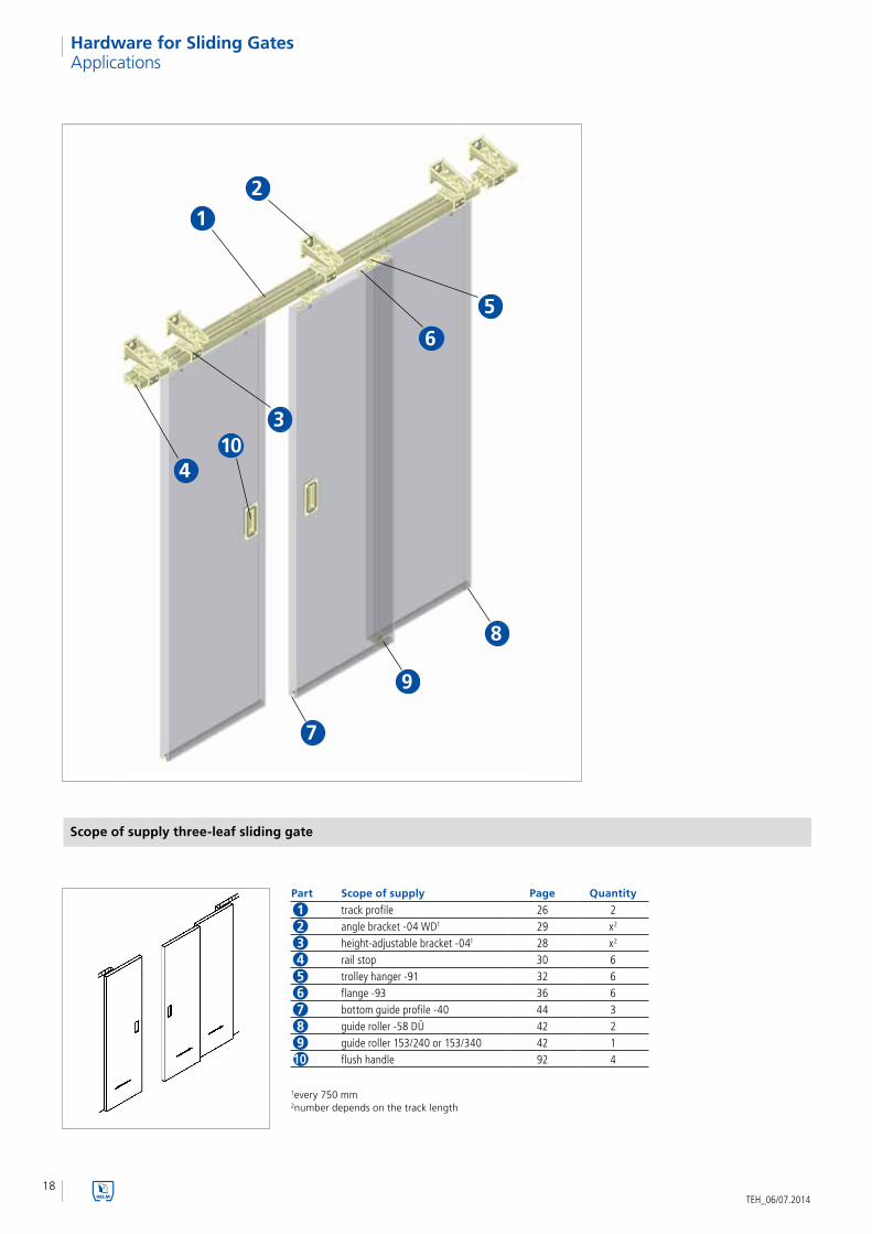
Part Scope of supply Page Quantity
track profile 26 2angle bracket -04 WD1 29 x2
height-adjustable bracket -041 28 x2
rail stop 30 6trolley hanger -91 32 6flange -93 36 6bottom guide profile -40 44 3guide roller -58 DÜ 42 2guide roller 153/240 or 153/340 42 1flush handle 92 4
Scope of supply three-leaf sliding gate

19
123456789
10
1
2
3
9
5
8
7
4
6
10
Gen
eral
Info
rmat
ion
TEH_06/07.2014
Hardware for Sliding GatesApplications
Scope of supply four-leaf sliding gate
Part Scope of supply Page Quantity
track profile 26 2angle bracket -04 WD1 29 x2
height-adjustable bracket -041 28 x2
rail stop 30 8trolley hanger -91 32 8flange -93 36 8bottom guide profile -40 44 4guide roller -58 DÜ 42 2guide roller 153/240 or 153/340 42 2flush handle 92 4
1every 750 mm 2quantity depends on the track length

20
12
3
4
5
8
7
6
9
123456789
TEH_06/07.2014
Hardware for Sliding Gates
1every 750 mm 2number depends on the track length
Part Scope of supply Page Quantity
track profile 26 3height-adjustable bracket -041 28 x2
rail stop 30 6trolley hanger -91 32 6flange -93 36 6bottom guide profile -40 44 3guide roller -58 DÜ 42 1guide roller 153/240 or 153/340 42 2flush handle 92 2
Scope of supply three-leaf sliding gate
Applications

21
12
9
4
8
7
11
5
10
3
6
123456789
1011
Gen
eral
Info
rmat
ion
TEH_06/07.2014
Hardware for Sliding Gates
Scope of supply one-leaf sliding gate with swing element
1every 750 mm 2quantity depends on the track length
Part Scope of supply Page Quantity
track profile 26 1open side wall mounting bracket -011 26 x2
rail stop 30 2trolley hanger -91 32 1trolley hanger -92 34 1flange -93 36 2door stop -60 38 1bottom guide profile -40 44 1guide roller -58 DÜ 42 1hinge 3flush handle 92 2
Applications

22TEH_06/07.2014
Hardware for Sliding Gates
Part no. 100 300 400 500 600 700
Profile 100 300 400 500 600 700b 38 50 60 80 100 115b1 20 24 30 38 50 60d 8 11 13 17 22 26d1 M10 M12 M16 M20 M24 M30h 107+10 135+20 165+20 213+17 274+75 348+75h1 50+10 63+20 75+20 97+17 125+75 150+75h2 25 33 37 47.5 65 74h3 8 11 15 20 25 30h4 10 13 16.5 17.5 25 30
The figure depicts the installation cross-section with the trolley hangers no. 191 to no. 791 and open side wall mounting brackets no. 101 to no. 701.
Installation Cross-section and Installation Dimensions
Installation cross-section with open side wall mounting bracket

23
Tech
nic
al in
form
atio
n
TEH_06/07.2014
Hardware for Sliding GatesInstallation Cross-section and Installation Dimensions
Installation cross-section with lock joint ceiling bracket
The figure depicts the installation cross-section with the trolley hangers no. 191 to no. 791 and lock joint ceiling brackets no. 102 to no. 702.
Part no. 100 300 400 500 600 700
Profile 100 300 400 500 600 700b 90 115 130 170 211 260b1 20 24 30 38 50 60d1 M10 M12 M16 M20 M24 M30h 86+10 110+20 130+20 172+17 221+75 285+75h1 50+10 63+20 75+20 97+17 125+75 150+75h2 25 33 37 47.5 65 74h3 8 11 15 20 25 30

24TEH_06/07.2014
Hardware for Sliding Gates
Part no. 100 300 400 500 600 700
Profile 100 300 400 500 600 700 with WDb1 20 24 30 38 50 60b2 21+17 25+15 30+10 42+40 50+30 57.5+120d 13 17 17 18 18 18d1 M10 M12 M16 M20 M24 M30h 156+30 200+45 220+35 290+75 340+110 410+160h1 50+10 63+20 75+20 97+17 125+75 150+75h2 25 33 37 47.5 65 74h3 8 11 15 20 25 30h4 16.5 20 20 25 25 30
The figure depicts the installation cross-section with the trolley hang-ers no. 191 to no. 791 in combina-tion with open side wall mounting brackets no. 104 W to no. 604 W and height-adjustable bracket no. 104 to no. 704.
Installation Cross-section and Installation Dimensions
Installation cross-section with height-adjustable bracket and wall mounting bracket

25
Tech
nic
al in
form
atio
n
TEH_06/07.2014
Hardware for Sliding Gates
The figure depicts the installation cross-section with the trolley hang-ers no. 191 to no. 791 in combination with open side wall mounting brack-ets no. 104 WD to no.704 WD and height-adjustable bracket no. 104 to no. 704.
Installation cross-section with height-adjustable bracket and double wall mounting bracket
Part no. 100 300 400 500 600 700
Profile 100 300 400 500 600 700b1 20 24 30 38 50 60b2 min. 21 25 30 42 50 57.5b3 max. 85 135 135 190 190 180d 13 17 17 18 18 18d1 M10 M12 M16 M20 M24 M30h 156+30 200+45 220+35 290+75 340+110 410+160h1 50+10 63+20 75+20 97+17 125+75 150+75h2 25 33 37 47.5 65 74h3 8 11 15 20 25 30h4 16.5 20 20 25 25 30
Installation Cross-section and Installation Dimensions
26TEH_06/07.2014
Hardware for Sliding GatesSingle Parts
Part no. 100 300 400 500 600 700
Profile 100 300 400 500 600 700
b 30 40 48,5 65/64* 80 90
b1 8 11 15 18 22 25
h 28 35 43,5 60/59* 75 110
s 1,75/1,6* 2,75/3,0* 3,2/3,1* 3,6/3,5* 4,5 6,5
EDP no.
stock length, zinc-plated 010020 030020 040020 050020 060020 070020
cut to length, zinc-plated 010021 030021 040021 050021 060021 070021
stock length, steel blank 010010 030010 040010 050010 060010 070010
cut to length, steel blank 010011 030011 040011 050011 060011 070011
stock length, stainless steel 010030 030035 040030 050030 - -
cut to length, stainless steel 010031 030036 040031 050031 - -
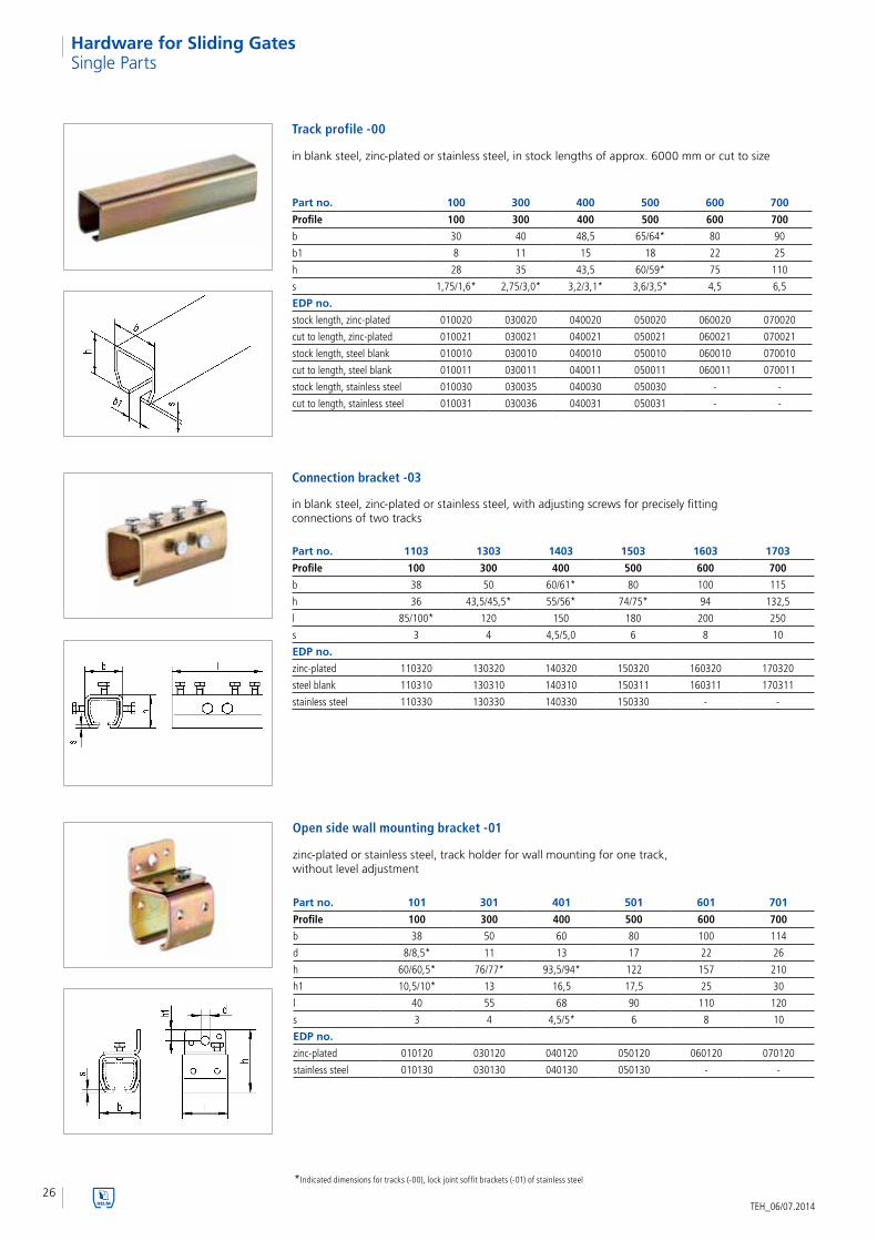
Track profile -00 in blank steel, zinc-plated or stainless steel, in stock lengths of approx. 6000 mm or cut to size
Part no. 1103 1303 1403 1503 1603 1703
Profile 100 300 400 500 600 700
b 38 50 60/61* 80 100 115
h 36 43,5/45,5* 55/56* 74/75* 94 132,5
l 85/100* 120 150 180 200 250
s 3 4 4,5/5,0 6 8 10
EDP no.
zinc-plated 110320 130320 140320 150320 160320 170320
steel blank 110310 130310 140310 150311 160311 170311
stainless steel 110330 130330 140330 150330 - -
Connection bracket -03
in blank steel, zinc-plated or stainless steel, with adjusting screws for precisely fitting connections of two tracks
Part no. 101 301 401 501 601 701
Profile 100 300 400 500 600 700
b 38 50 60 80 100 114
d 8/8,5* 11 13 17 22 26
h 60/60,5* 76/77* 93,5/94* 122 157 210
h1 10,5/10* 13 16,5 17,5 25 30
l 40 55 68 90 110 120
s 3 4 4,5/5* 6 8 10
EDP no.
zinc-plated 010120 030120 040120 050120 060120 070120
stainless steel 010130 030130 040130 050130 - -
Open side wall mounting bracket -01 zinc-plated or stainless steel, track holder for wall mounting for one track, without level adjustment
*Indicated dimensions for tracks (-00), lock joint soffit brackets (-01) of stainless steel

27
HEL
M 1
00 -
700
, Har
dw
are
for
Slid
ing
Gat
es
TEH_06/07.2014
Hardware for Sliding Gates
Part no. 101 D 301 D 401 D 501 D
Profile 100 300 400 500
b 83 100 120/140/150 165
d 11,5 13 17 17
h 70,5 91 112,5 130
h1 14 14 18,5 18,5
l 40 55 68 90
y 45 50 60/80/90 85
EDP no.
zinc-plated 010121 030121 040121 050121
zinc-plated (80) - - 040125 -
zinc-plated (90) - - 040129 -
Open double side wall mounting bracket -01 D
zinc-plated, double track holder for wall mounting for two tracks, without level adjustment
Single Parts
Part no. 102 302 402 502 602 702
Profile 100 300 400 500 600 700
b 88/90* 115 130 170 211 260
b1 63 ± 6,5/65 ±6,8* 80 ± 8 94 ± 8 123(124*) ± 10 149 ± 12 178,5 ± 23,5
d 8,5/8,2* 11 13 17 22 22
h 39 50/51* 59,5/60* 81 104 144,5
l 40 50 60 80 100 100
s 3 4 4,5/5* 6 8 10
EDP no.
zinc-plated 010220 030220 040220 050220 060220 070220
stainless steel 010230 030230 040230 050230 - -
Part no. 102 D 302 D 402 D 502 D
Profile 100 300 400 500b 133 165/185 190/220 260b1 108 ± 7 129/149 ±8 152/182 ±8 214 ± 10
d 8,5 13 13 17
h 39 52 62,5 85
l 40 60 80 80
y 45 50/70 60/80/90 85
EDP no.
zinc-plated 010221 030221 040221 050221
zinc-plated (70) - 030222 - -
zinc-plated (80) - - 040225 -
zinc-plated (90) - - 040229 -
Lock joint ceiling bracket -02
zinc-plated or stainless steel, track holder for ceiling mounting for one track, without level adjustment
Double lock joint ceiling bracket -02 D
zinc-plated, double track holder for ceiling mounting for two tracks, without level adjustment
*Indicated dimensions for ceiling fixing parts (-02) of stainless steel

28TEH_06/07.2014
Hardware for Sliding GatesSingle Parts
Part no. 1104 1304 1404 1504 1604 1704
Profile 100 300 400 500 600 700
b 38 50 60 80 100 115
h 36 46/45,5* 54,5/55* 75 94 132,5
l 40 55 68 90 110 120
s 3 4 4,5/5 6 8 10
EDP no.
steel blank1 110410 130410 140410 150410 160410 170410
steel blank2 11041001 13041001 14041001 15041001 16041001 17041001
stainless steel1 110430 130430 140430 150430
stainless steel2 11043001 13043001 14043001 15043001
Lock joint soffit bracket -04
in blank steel or stainless steel, with top (on request also lateral) counter screw, usable for welded installations
Height-adjustable bracket -04
zinc-plated or stainless steel, track holder with level adjustment, can be used with wall mounting bracket -04 W or -04 WD
Part no. 104 304 404 504 604 704
Profile 100 300 400 500 600 700
b 38 50 60 80 100 115
d M10 M16 M16 M20 M20 M30
h 98/102* 135/135,5* 141,5/145* 208/207,5* 226,5 322
h1 64/66* 89/90* 87/90* 133/132,5* 132,5 189
I 40 55 68 90 110 120
s 3 4 4,5/5* 6 8 10
EDP no.
zinc-plated 010420 030420 040420 050420 060420 070420
stainless steel 010430 030430 040430 050430 - -
Bracket -04 F
zinc-plated, combination with wall mounting bracket, especially for the use with fire protection gates
Part no. 404 F 504 F 604 F
Profile 400 500 600
b 60 80 100
d M16 M20 M20
h 95,5 113 132
h1 41 38 38
I 68 90 110
EDP no.
zinc-plated 040428 050424 060424
*Indicated dimensions for lock joint soffit brackets (-04) and height-adjustable brackets (-04) of stainless steel
1screw on top2screw on the side

29
HEL
M 1
00 -
700
, Har
dw
are
for
Slid
ing
Gat
es
TEH_06/07.2014
Hardware for Sliding GatesSingle Parts
Part no. 104 W
Profile 100
b 50
d 13
d1 11
h 50
h1 16,5
I 50
s 5
EDP no.
zinc-plated 010421
stainless steel 010431
Wall mounting bracket 104 W
zinc-plated or stainless steel, bracket fixing with lateral adjustment option, can be used with height-adjustable bracket 104
Part no. 404 W 604 W
Profile 300/400 500/600
b 75 120
d 17 18
d1 17 21
h 80 110
h1 20 25
I 60 102
EDP no.
zinc-plated 040421 060421
stainless steel 040431 060431
Wall mounting bracket -04 W
zinc-plated or stainless steel, bracket fixing with lateral adjustment option, can be used with height-adjustable bracket -04
Part no. 104 WD
Profile 100
b 60
d 13
d1 11
h 50
h1 16,5
I 100
s 6
EDP no.
zinc-plated 010422
stainless steel 010432
Double wall mounting bracket 104 WD
zinc-plated or stainless steel, bracket fixing with lateral adjustment option, can be used with two height-adjustable brackets 104

30TEH_06/07.2014
Hardware for Sliding GatesSingle Parts
Double wall mounting bracket -04 WD
zinc-plated or stainless steel, bracket fixing with lateral adjustment option, can be used with two height-adjustable brackets -04
Double wall mounting bracket -04 WDF
zinc-plated, bracket fixing with lateral adjustment option, can also be used with bracket -04 F
Rail stop 100 P - 500 P
zinc-plated or stainless steel, travel path limiter, prevents the trolley hangers from running off the rail. Not suitable for the sole stopping of the sliding leaves!
Part no. 404 WD 604 WD 704 WD
Profile 300/400 500/600 700
b 75 120 120
d 17 18 18
d1 17 21 32
h 80 110 110
h1 20 25 25
I 155 212 212
EDP no.
zinc-plated 040422 060422 070422
stainless steel 040432 060432 -
Part no. 404 WDF 604 WDF
Profile 300/400 500/600
b 75 120
d 17 18
d1 17 21
h 80 110
h1 20 25
I 100 162
EDP no.
zinc-plated 040422-100 060423
Part no. 100 P 300 P 400 P 500 P
Profile 100 300 400 500
b 25 32 39 55
h 23 27 34 51
I 25,5 33,5 33,5 50
EDP no.
zinc-plated 010080 030080 040080 050080
stainless steel 010081 - - -
31
HEL
M 1
00 -
700
, Har
dw
are
for
Slid
ing
Gat
es
TEH_06/07.2014
Hardware for Sliding GatesSingle Parts
Rail stop 1300 P-1600 P
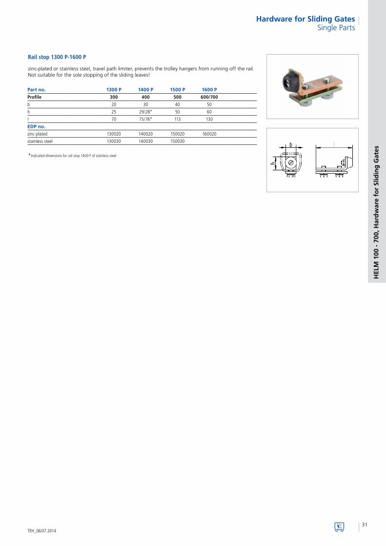
zinc-plated or stainless steel, travel path limiter, prevents the trolley hangers from running off the rail. Not suitable for the sole stopping of the sliding leaves!
Part no. 1300 P 1400 P 1500 P 1600 P
Profile 300 400 500 600/700
b 20 30 40 50
h 25 29/28* 50 60
I 70 75/76* 113 130
EDP no.
zinc-plated 130020 140020 150020 160020
stainless steel 130030 140030 150030
*Indicated dimensions for rail stop 1400 P of stainless steel
32TEH_06/07.2014
Hardware for Sliding Gates
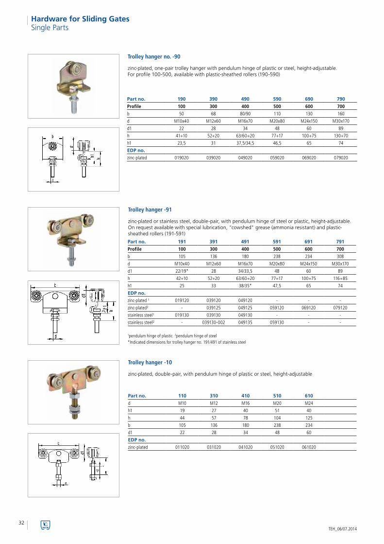
Part no. 190 390 490 590 690 790
Profile 100 300 400 500 600 700
b 50 68 80/90 110 130 160
d M10x40 M12x60 M16x70 M20x80 M24x150 M30x170
d1 22 28 34 48 60 89
h 41+10 52+20 63/60+20 77+17 100+75 130+70
h1 23,5 31 37,5/34,5 46,5 65 74
EDP no.
zinc-plated 019020 039020 049020 059020 069020 079020
Trolley hanger no. -90
zinc-plated, one-pair trolley hanger with pendulum hinge of plastic or steel, height-adjustable. For profile 100-500, available with plastic-sheathed rollers (190-590)
Single Parts
Trolley hanger -10
zinc-plated, double-pair, with pendulum hinge of plastic or steel, height-adjustable
Part no. 110 310 410 510 610
d M10 M12 M16 M20 M24
h1 19 27 40 51 40
h 44 57 78 104 125
b 105 136 180 238 234
d1 22 28 34 48 60
EDP no.
zinc-plated 011020 031020 041020 051020 061020
Part no. 191 391 491 591 691 791
Profile 100 300 400 500 600 700
b 105 136 180 238 234 308
d M10x40 M12x60 M16x70 M20x80 M24x150 M30x170
d1 22/19* 28 34/33,5 48 60 89
h 42+10 52+20 63/60+20 77+17 100+75 116+85
h1 25 33 38/35* 47,5 65 74
EDP no.
zinc-plated ¹ 019120 039120 049120 - - -
zinc-plated² - 039125 049125 059120 069120 079120
stainless steel¹ 019130 039130 049130 - - -
stainless steel² - 039130-002 049135 059130 - -
Trolley hanger -91
zinc-plated or stainless steel, double-pair, with pendulum hinge of steel or plastic, height-adjustable. On request available with special lubrication, "cowshed" grease (ammonia resistant) and plastic-sheathed rollers (191-591)
1pendulum hinge of plastic 2pendulum hinge of steel*Indicated dimensions for trolley hanger no. 191/491 of stainless steel

33
HEL
M 1
00 -
700
, Har
dw
are
for
Slid
ing
Gat
es
TEH_06/07.2014
Hardware for Sliding GatesSingle Parts
Trolley hanger -12
zinc-plated, double-pair, with pendulum hinge of plastic or steel. No adjustment and detaching option. Benefit: low headroom installation
Part no. 112 312 412 512
b 105 136 180 238
h 16 25 30 39,5
b1 100 160 210 265
h1 4 10 10 12
b2 20 30 40 50
d 22 28 34 48
EDP no.
zinc-plated 011220 031220 041220 051220
Part no. 191 S 391 S 491 S 591 S 691 S 791 S
Profile 100 300 400 500 600 700
b 105 136 180 238 234 308
b1 50 68 90 110 60 80
d 22 28 34 48 60 89
h 11,75 16 20,5 28 18,5 29
s 3 4,5 6 8 15 19,5
EDP no.
zinc-plated 019121 039121 049121 059121 069121 079121
Trolley hanger -91 S
zinc-plated, double-pair, with pendulum hinge of plastic or steel. Web has to be welded on, no adjustment option. Benefit: low headroom installation
Double hinge trolley hanger -00
zinc-plated, double-pair, with pendulum hinge of plastic or steel, including flange and double hinge for tight-closing gate installations
Part no. 300 400 500
Profile 300 400 500
b 136 180 238
b1 160 210 264
b2 24 30 38
d 28 34 48
h 82 101,5 122
h1 11 15 20
EDP no.
zinc-plated 039123 049123 059123

34TEH_06/07.2014
Hardware for Sliding GatesSingle Parts
Trolley hanger -91/85
zinc-plated, double-pair, with pendulum hinge of steel for fire protection sliding gates, height-adjustable
Part no. 491/85 591/85 691/85
Profile 400 500 600
b 180 238 234
d M16x80 M20x110 M24x180
d1 34 48 60
h 77+12 98+29 116+79
h1 49 65 69,5
EDP no.
zinc-plated 049124 059124 069124
Trolley hanger -91 EL
zinc-plated double-pair, with pendulum hinge of plastic or steel, with 2 transverse rollers for electrically operated gates, height-adjustable
Part no. 391 EL 491 EL 591 EL 691 EL 791 EL
Profile 300 400 500 600 700
b 206 270 358 374 468
d M12x60 M16x70 M20x80 M24x150 M30x160
d1 28 34 48 60 89
h 52+20 63/60+20 77+17 100+75 125+75
h1 33 38 47,5 65 74
EDP no.
zinc-plated 039122 049122 059122 069122 079122
trolley hanger -92
double-pair, with pendulum hinge, with counter pressure roller for sliding leaves with top-hung gates, height-adjustable
Part no. 192 392 492 592 692
Profile 100 300 400 500 600
b 65 90 120 160 190
d M10x40 M12x60 M16x70 M20x90 M24x160
d1 22 28 34 48 60
h 40+8 52+20 59+18 77+17 100+75
h1 25 32,8 34 36,4 57
EDP no.
cast iron painted 019220 – – – –
zinc-plated – 039220 049220 059220 0692201dimensions zinc-plated
zinc-plated painted
zinc-plated painted

35
HEL
M 1
00 -
700
, Har
dw
are
for
Slid
ing
Gat
es
TEH_06/07.2014
Hardware for Sliding GatesSingle Parts
Trolley hanger -91 SEL
zinc-plated double-pair, with pendulum hinge of plastic or steel, with 2 transverse rollers for electrical operated gates. Web has to be welded on, no adjustment option. Benefit: low headroom installation
Part no. 391 SEL 491 SEL 591 SEL 691 SEL 791 SEL
Profile 300 400 500 600 700
b 206 270 358 374 468
b1 68 90 110 60 80
d 28 34 48 60 89
h 16 20,5 28 19 29
s 4,5 6 8 15 19,5
EDP no.
zinc-plated 039112 049112 059112 069112 079112
trolley hanger -09
zinc-plated, one-pair, with pendulum hinge of plastic or steel, height-adjustable
Part no. 109 309 409 509 609
Profile 100 300 400 500 600
b 50 68 90 110 60
d M10 M12 M16 M20 M24
d1 22 27,9 34 48 60
h 44 50 75,5 111 125
h1 19 22 35 63 50
EDP no.
zinc-plated 010920 030920 040920 050920 060920
Trolley hanger -11
zinc-plated, one-pair adjustment and detaching option. Benefit: low headroom installation
Part no. 111 311 411 511
Profile 100 300 400 500
b 50 68 90 110
b1 100 160 210 265
b2 20 30 40 50
d 22 27,9 34 48
h 16 23,5 29,3 39,5
h1 4 10 10 12
EDP no.
zinc-plated 011120 031120 041120 051120

36TEH_06/07.2014
Hardware for Sliding Gates
Flange -93 S
in steel blank, for steel leaves, for welding on, with thread positioned in the centre
Part no. 193 S 393 S 493 S 593 S 693 S 793 S
Profile 100 300 400 500 600 700
b 20 24 30 38 50 60
d M10 M12 M16 M20 M24 M30
h 8 11 15 20 25 30
I 100 100 120 140 150 180
EDP no.
steel blank 019311 039311 049311 059311 069311 079311
Single Parts
Part no. 193 393 493 593 693 793
Profile 100 300 400 500 600 700
b 20 24 30 38 50 60
d M10 M12 M16 M20 M24 M30
d1 6 5,3 6,8 7,5 11 11
h 8 11 15 20 25 30
I 100 160 210 264 350 500
EDP no.
zinc-plated 019320 039320 049320 059320 069320 079320
stainless steel 019330 039330 049330 059330 - -
Flange -93
zinc-plated or stainless steel, for timber leaves, for screwing on, with thread positioned in the centre
Reinforcing soffit bracket -98
zinc-plated, for timber leaves, for the additional stabilisation of the flange fixing
Part no. 198 498 698
Profile 100 300/400 500/600
leaf thicknesses 20-40 35-70 55-105
l 50 100 150
d 11 17 26
h 82 107 160
s 3 3 5
EDP no.
zinc-plated 019820 049820 069820
no. 193
no. 393-793
no. 193
no. 393-793
no. 193 S
no. 393 S-793 S
no. 193 S
no. 393 S-793 S

37
HEL
M 1
00 -
700
, Har
dw
are
for
Slid
ing
Gat
es
TEH_06/07.2014
Hardware for Sliding GatesSingle Parts
Part no. 196 S 396 S 496 S 596 S 696 S 796 S
Profile 100 300 400 500 600 700
b 20 24 30 38 50 60
d M10 M12 M16 M20 M24 M30
h 8 11 15 20 25 30
I 100 100 120 140 150 180
l1 10 12 15,5 20 20 25
EDP no.
steel blank 019611 039611 049611 059611 069611 079611
Flange -96 S
in steel blank, for steel leaves, for welding on, with thread at the side
Part no. 194 394 494 594
Profile 100 300 400 500
b 20 30 35 40
d M10 M12 M16 M20
d1 4,8 5,9 7 8,4
h 124 158 210 260
I 124 158 200 255
l1 15 20 20 30
EDP no.
zinc-plated 019420 039420 049420 059420
Angle bracket -94
zinc-plated, for timber leaves, for screwing on or countersinking, with thread on the side
Part no. 195 395 495 595
Profile 100 300 400 500
b 20 30 35 40
d M10 M12 M16 M20
d1 4,8 5,9 7 8,4
h 124 158 210 260
I 124 158 200 255
l1 70 80 120 155
EDP no.
zinc-plated 019520 039520 049520 059520
Angle bracket -95
zinc-plated, for timber leaves, for screwing on or countersinking, with thread positioned in the centre
no. 196 S
no. 396 S-796 S
no. 196 S
no. 396 S-796 S

38TEH_06/07.2014
Hardware for Sliding Gates
Part no. 360 460
door weight up to 200 kg 300 kg
b 40 50
d 10 x 70 10 x 70
h 50 60
I 113 130
EDP no.
zinc-plated 036020 046020
door stop 360/460
zinc-plated, with plugs and screws
Door stop 560 L/560
zinc-plated, with steel spring
Part no. 560 L 560
door weight up to 600 kg 2000 kg
b 110 110
b1 60 60
h 90 110
h1 60 80
I 243 343
l1 200 200
EDP no.
zinc-plated 056020 056021
Part no. 256
b 30
b1 20
h 43
I 180
s 7
EDP no.
aluminium 025650
Handle 256 LM
aluminium, silver anodised
Single Parts

39
HEL
M 1
00 -
700
, Har
dw
are
for
Slid
ing
Gat
es
TEH_06/07.2014
Hardware for Sliding GatesSingle Parts
Part no. 459 DÜ 559 DÜ
d 38,5 73,5
h 39 57
h1 12 13
h2 21,5 34
EDP no.
plastic roller 045961 055961
Pressure roller -59 DÜ
plastic roller with plug and screw
Wedge -55
plastic, used in combination with pressure rollers and screwed on the leaf
Part no. 355 555
b 30 40
d 6.4 6.5
h 20 25
I 110 120
EDP no.
plastic 035560 055560
Tortoiseshell-shaped guide 418
plastic glass fibre reinforced, with screws and plugs
Part no. 418
b 74
h 32
I 152
EDP no.
plastic 041800

40TEH_06/07.2014
Hardware for Sliding Gates
Guide 514 DÜ
malleable cast iron with screws and plugs
Part no. 514 DÜ
b 19
h 23
I 150
EDP no.
malleable cast iron 051471
Part no. 216 316
bottom guide profile 240 340
b 12.5 19.5
h 14.5 19.5
I 49.5 69.5
EDP no.
plastic 021660 031660
Guide glide -16
plastic, with screws and plugs
Single Parts
Part no. 216 S 316 S
bottom guide profile 240 340
b 13.5 21.6
h 14.6 19.5
I 49.5 69.5
EDP no.
plastic 021661 031661
Guide glide -16 S
plastic, with screws and plugs, rattle-proof guide

41
HEL
M 1
00 -
700
, Har
dw
are
for
Slid
ing
Gat
es
TEH_06/07.2014
Hardware for Sliding GatesSingle Parts
Glide roller on plate 459 PL
plastic roller, on base plate
Part no. 459 PL
b 36
b1 42
d 39
h 33
I 80
s 6
EDP no.
plastic roller 045962
Double guide roller 659
plastic or steel rollers, on base platecontinuous adjustment to the leaf thickness by inclining the base plate
Part no. 659
b 50
d 50
h 59/811
I 300
l1 75
s 6
EDP no.
plastic roller 065921
steel roller 065920
1dimension "h" for plastic roller
Guide roller -49 S
with screw joint, zinc-plated or stainless steel with plastic or brass roller
Part no. 349 S 449 S 549 S
bottom guide profile 340 440 540
d 19 32 50
d1 M10 M16 M20
h 47,3 63 81
h1 32 42,5 52
EDP no.
plastic roller¹ 034962 044962 054962
plastic roller² 03496230 - -
brass roller¹ 034942 044942 054942
1screw joint zinc-plated 2screw joint stainless steel

42TEH_06/07.2014
Hardware for Sliding Gates
Guide roller -49 N
with rivet joint, zinc-plated with plastic or brass roller
Part no. 349 N 449 N 549 N
bottom guide profile 340 440 540
d 19 32 50
d1 9.8 15.8 19.8
h 35 46 67
h1 27 36 47
EDP no.
plastic roller 034963 044963 054963
brass roller 034943 044943 054943
Single Parts
Guide roller -58 DÜ
with screw and plug, with plastic or brass roller
Part no. 258 DÜ 358 DÜ 458 DÜ 558 DÜ
bottom guide profile 240 340 440 540
d 12 19 32 49.5
h 16.5 24 39 48.5
h1 12 19.5 30 39.5
EDP no.
plastic roller 025860 035860 045860 055860
brass roller 025840 035840 - -
Part no. 153/240 153/340
bottom guide profile 240 340
b 40 40
d 12 19
h 36 36
h1 19 28
I 41 41
l1 22+10 22+10
EDP no.
plastic roller 015320 015321
Guide roller -153 -40
adjustable, zinc-plated angle bracket with plastic roller

43
HEL
M 1
00 -
700
, Har
dw
are
for
Slid
ing
Gat
es
TEH_06/07.2014
Hardware for Sliding GatesSingle Parts
Part no. 154/240
bottom guide profile 240
b 60
b1 12.5
h 41
h1 20.5
I 55
l1 25+20
EDP no.
plastic glide 015460
Plastic glide 154/240
adjustable, zinc-plated angle bracket with plastic glide
Guide roller 249 F
with flange joint and roller at the side, in combination with bottom guide profile no. 240 with plastic or brass roller
Part no. 249 F
bottom guide profile 240
b 20
d 12
d1 4.2
h 18
h1 14
I 90
EDP no.
plastic roller 024961
brass roller 024941
Part no. 349 F 449 F 549 F 649 F
bottom guide profile 340 340/440 440/540 540
b 24 30 38 50
d 19 191/322 322/49.53 49.5
d1 5.3 6.8 7.5 11
h 36 40¹/502 562/663 77
h1 25 25¹/352 362/463 52
I 160 210 264 350
EDP no.
plastic roller 034961 044961¹ 054961² 064961
- 0449642 0549643 -
brass roller 034941 044941¹ 054941² -
- 0449442 0549443 -
Guide roller -49 F
with flange joint and roller in the centre, in combination with bottom guide profile no. 340, 440 and 540 with plastic or brass roller
1for bottom guide profile no. 340 2for bottom guide profile no. 440 3for bottom guide profile no. 540

44TEH_06/07.2014
Hardware for Sliding Gates
Part no. 249 349 449 549
bottom guide profile 240 340 340/440 440/540
b 20 30 35 40
d 12 19 191/322 322/49.53
h 138 182 2351/2462 2962/3063
h1 124 158 210 260
I 124 158 200 255
l1 15 20 20 30
EDP no.
plastic roller 024960 034960 0449601 054960²
- - 0449652 0549653
brass roller 024940 034940 0449401 054940²
- 0449452 0549453
Guide roller -49
with angle bracket fixing and roller at the side, in combination with bottom guide profile no. 240-540 with plastic or brass roller
1for bottom guide profile no. 340 2for bottom guide profile no. 440 3for bottom guide profile no. 540
Single Parts
Guide roller -49 1/2
with angle bracket fixing and roller in the centre, in combination with bottom guide profile no. 240-540with plastic or brass roller
Part no. 249/1/2 349/1/2 449/1/2 549/1/2
bottom guide profile 240 340 340/440 440/540
b 20 30 35 40d 12 19 191/322 322/49.53
h 138 182 2351/2462 2962/3063
h1 124 158 210 260I 124 158 200 255l1 70 80 120 155EDP no.plastic roller 024968 034968 044968¹ 0549682
- - 0449692 0549693
brass roller 024948 034948 044948¹ 0549482
- - 0449492 0549493
Part no. 240 340 440 540
Profile
b 15 25 40 60
d 5.5 6.2 6.0 6.0
h1 15 25 40 50
h 18 28 43 -
s 1 2 3 4
EDP no.
stock length1 024010 034013 044013 054013
cut to length1 024019 034019 044019 054019
stock length2 - 034036 - -
cut to length2 - 034037 - -
Bottom guide profile -40
perforated, zinc-plated or stainless steel
1zinc-plated 2stainless steel
1for bottom guide profile no. 340 2for bottom guide profile no. 440 3for bottom guide profile no. 540

45
HEL
M 1
00 -
700
, Har
dw
are
for
Slid
ing
Gat
es
TEH_06/07.2014
Hardware for Sliding GatesSingle Parts
Part no. 240 340 440 540
Profile
b 15 25 40 60
h 15 25 40 50
s 1 2 3 4
EDP no.
stock length1 024016 034016 044016 054016
cut to length1 024018 034018 044018 054018
stock length2 - 034011 - -
cut to length2 - 034012 - -
Bottom guide profile -40
not perforated, zinc-plated or stainless steel
1zinc-plated 2stainless steel

46TEH_06/07.2014
Hardware for Sliding Gates
Part no. 971 S 972 S
max. bearing capacity kg 160 375
b 70 100
h 300 350
l 41 60
n 12,5 15,3
s 10 10
EDP no.
Steel roller 097111 097211
Suspended roll 97- S
Steel roller with protection cap, primed, with ball bearing
Part no. 973 S
max. bearing capacity kg 150
b 92
b1 50
h 400
l 50
n 10
s 8
EDP no.
Steel roller 097311
Suspended roll -973 S
Steel roller with protection cap, plated, blue chromated, with ball bearing
Part no. 912 913
max. bearing capacity kg 200 350
b 70 70
d M16 M22
h 376,5 381,5
l 41 41
n 12,5 12,5
EDP no.
Steel roller 091210 091310
Relief roll 91 - for folding gates
Steel roller, plated, with ball bearing. The roll is to relieve the gate hinges.Use: e. g. exterior folding gates
Suspended rolls

47
b
s
h2h1
HEL
M 1
00 -
700
, Har
dw
are
for
Slid
ing
Gat
es
TEH_06/07.2014
Hardware for Sliding GatesSpecial Rollers up to 8000 kg door weight
For door weights up to max. 3000 kgor up to max. 8000 kg
Part no. 1T-007 1T-008
max. bearing capacity per trolley hanger (kg) 4000 1500
matching U profile steel h1 [ ] 200 [ ] 160
l 660 600
l1 200 200
b 60 50
h1 360 320
h2 174 172
s 25 20
EDP no.
steel, primed 100710 100810
Special rollers 1-T
of steel, with ball bearings, for door weights up to 8000 kg, primed
Special rollers for big hall gates, radiation protection doors or hangar gates. These are used with U-profile steel 160 (DIN 1026 -1), which has to be supplied by the customer. Also the relevant mounting of the profiles is effected by the customer.

48TEH_06/07.2014
Hardware for Sliding Gates
Required information for top hung sliding gates
Number of required installations _________________ pieces Installation type ________ (see fig. 1 - fig. 12 bottom)
Number of leaves _________________ Leaf thickness ________________________ mm
Leaf widths _________________ mm Leaf material ______________________________
door weight ______________________ kg
Leaf material
Straight sliding installations
Type of drive manual electrical (please observe DIN 13241-1)
track mounting wall mounting ceiling mounting
height-adjustable by the customer
bottom guide bottom guide profile no. 240 - 540 Part no. _______________________________
guide roller Part no. _______________________________
door handles*
door pull no. 256 Part no.: _______________________________
*more door handles can be found in the catalogue (K3) product range KWS
fig. 1
fig. 2
fig. 3
fig. 4
fig. 5
fig. 6
fig. 7
fig. 8
fig. 9
fig. 10
fig. 11
fig. 12
timber steel
Installation types
Company ____________________________________________
Name ______________________________________________
Street ______________________________________________
Postcode/city _________________________________________
Supply exclusively through specialised trade. Please indicate your specialist dealer if appropriate: ______________________________
Telephone ____________________________________________
Fax ______________________________________________
E-mail ______________________________________________
Contact person _____________________________
Enquiry Form
Woelm GmbH I Hasselbecker Str. 2- 4 I D - 42579 Heiligenhaus I Phone: + 49 (0) 20 56 - 18 - 0 I Telefax: + 49 (0) 20 56 - 18 - 21
Woelm Austria GmbH I Seewalchen 5a I A - 5201 Seekirchen I Phone: + 43 (0) 62 12 - 25 - 02 I Telefax: + 43(0) 62 12 - 69 - 95
Order Enquiry Date ________________

49
Ap
pen
dix
TEH_06/07.2014
Hardware for Sliding Gates
50
lö mm
tlöm m
t
TEH_06/07.2014
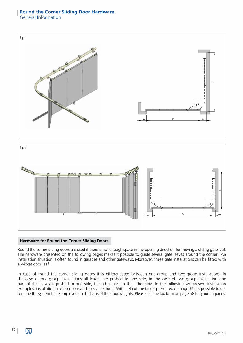
Round the Corner Sliding Door Hardware
fig. 2
Hardware for Round the Corner Sliding Doors
Round the corner sliding doors are used if there is not enough space in the opening direction for moving a sliding gate leaf. The hardware presented on the following pages makes it possible to guide several gate leaves around the corner. An installation situation is often found in garages and other gateways. Moreover, these gate installations can be fitted with a wicket door leaf.
In case of round the corner sliding doors it is differentiated between one-group and two-group installations. In the case of one-group installations all leaves are pushed to one side, in the case of two-group installation one part of the leaves is pushed to one side, the other part to the other side. In the following we present installation examples, installation cross-sections and special features. With help of the tables presented on page 55 it is possible to de-termine the system to be employed on the basis of the door weights. Please use the fax form on page 58 for your enquiries.
fig. 1
General Information

51
1 6
5
4
9
8
7
11
2
8
10
3
123456789
1011
Ro
un
d t
he
Co
rner
Slid
ing
Do
or
Har
dw
are
TEH_06/07.2014
Round the Corner Sliding Door Hardware
The clearance is divided in such a way that the single leaf widths are 550-850 mm.
Part Scope of supply Quantity
track 2 piece
bend radiuses 1 piece
connection brackets -03 2 piece
open side wall mounting bracket -01 every 700-750 mm
trolley hanger -86 or -24 4 piece
angle bracket -94 1 piece
angle bracket -96 3 piece
rail stop -00 P 2 piece
wedge -55 1 piece
pressure roller -59 Dü 1 piece
hinge -52 6 - 9 piece
Structure Hardware, one-group
Example four-leaf installation

52
123456789
10111213
1 3
2 45
5
5
6
6
7
7
7
88
9
9
10 11
12
1213
13
TEH_06/07.2014
Round the Corner Sliding Door Hardware
In case of big gate openings it is recommended to use two-group installations with one group moving to the right and the other to the left.Benefit: by splitting the installation into two groups the gate can consequently be operated more effortlessly.
Part Scope of supply Quantity
track 3 piece
bend radiuses 2 piece
connection brackets -03 4 piece
open side wall mounting bracket -01 every 700-750 mm
trolley hanger -22 2 piece
trolley hanger -86 or -24 6 piece
angle bracket -94 2 piece
angle bracket -96 6 piece
rail stop -00 P 2 piece
wedge -55 2 piece
pressure roller -59 Dü 2 piece
tortoiseshell-shaped guide 418 1 piece
hinge -52 12 - 18 piece
Example 2 x four-leaf installation
Structure Hardware, two-group
53
h1
b3
h3
b1
h5
h2
d1
b2
d2
d1
b3
h1
h
b
h4d
Ro
un
d t
he
Co
rner
Slid
ing
Do
or
Har
dw
are
TEH_06/07.2014
Round the Corner Sliding Door Hardware
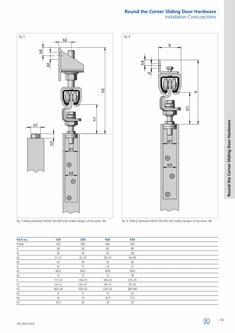
fig. 3
fig. 3 Sliding hardware HELM 100-500 with trolley hangers of the series -86
Part no. 100 300 400 500
Profile 100 300 400 500
b 38 50 60 80
b1 20 24 30 38
b2 21+17 25+15 30+10 42+40
b3 20 30 35 40
d 8 11 13 17
d1 M10 M12 M16 M20
d2 13 17 17 18
h 111+12 135+13 165+13 213+25
h1 54+12 63+13 76+13 97+25
h2 160+30 203+35 224+30 285+80
h3 8 11 15 20
h4 10 13 16.5 17.5
h5 16.5 20 20 25
fig. 4
fig. 4: Sliding hardware HELM 100-500 with trolley hangers of the series -86
Installation Cross-sections

54
h1
h2
d1
b3
h3
b1
h5
b2
d2b
h1
h
b3
d1
d
h4
TEH_06/07.2014
Round the Corner Sliding Door Hardware
fig. 5
fig. 5 Sliding hardware HELM 100-700 with trolley hangers of the series -24
fig. 6
fig. 6 Sliding hardware HELM 100-700 with trolley hangers of the series -24
Installation cross-sections
Part no. 100 300 400 500 600 700
Profile 100 300 400 500 600 700
b 38 50 60 80 100 115
b1 20 24 30 38 50 60
b2 21+17 25+15 30+10 42+40 50+30 57.5+120
b3 20 30 35 40 – –
d 8 11 13 17 22 26
d1 M10 M12 M16 M20 M24 M30
d2 13 17 17 18 18 18
h 111+7 142+7 171+4 215+15 272+68 366+67
h1 54+7 70+7 82+4 99+15 123+68 166+67
h2 160+25 210+25 230+20 290+70 335+115 425+150
h3 8 11 15 20 25 30
h4 10 13 16.5 17.5 25 30
h5 16.5 20 20 25 25 30

55
Ro
un
d t
he
Co
rner
Slid
ing
Do
or
Har
dw
are
TEH_06/07.2014
Round the Corner Sliding Door Hardware
Profile 100 300 400 500 600 700Series -22 Part no. - 322 422* 522 622 722
Load bearing capacity in kg per trolley hangeror max. door weight
Trolley no. 422 in zinc plated, trolley no. 322 and trolleys no. 522 - no. 722 cast iron painted.
- 65 100 200 400 700
Series -86 Part no. 186 386 486 586 - -
Load bearing capacity in kg per trolley hangeror max. door weight
45 85 150 300 - -
Series -24 Part no. 124 324 424 524 624 724
Load bearing capacity in kg per trolley hangeror max. door weight
45 85 150 300 600 1000
fig. 1
Load bearing capacity of the one and double-pair trolley hangers
Profile no. 100 300 400 500 600 700
blank • • • • • •
zinc-plated • • • • • •
stainless steel • • • •
We supply tracks, running gears as well as suspension material in six different sizes.The tracks are available in steel blank, zinc-plated and partly in stainless steel.
On the basis of load bearing capacity of one and double-pair trolley hangers the correct profile and hardware size can be determined with the help of table 1.
When determining the hardware size please take into account that the one-pair trolley hangers -22 are only used as final support rollers for two-group installations.
Determining the tracks
Profile no. 100 300 400 500 600 700
h 28.0 35.0 43.5 60.0 75.0 110.0
b 30.0 40.0 48.5 65.0 80.0 90.0
s 1.75 2.75 3.2 3.6 4.5 6.5
Track dimensions
Available track types
Load bearing capacity in kg per trolley hangeror max. door weight for electrical installations
- 70 120 240 - -
Load bearing capacity in kg per trolley hangeror max. door weight for electrical installations
- 70 120 240 475 700
no. 422

56TEH_06/07.2014
Round the Corner Sliding Door Hardware
The following radiuses guarantee a trouble-free movement of the trolley hangers through the bends. Depending on the radius (R) the oversizes (L) of the track bends can vary.
The track bends can be manufactured as various constructions according to the table (bend types).
Possible radiuses (R) 205 220 300 320 400 410 415 450 605 610 630 650 790 875 905 1035 all if R >
profile no. 100 • • • • 900
profile no. 300 • • • 950
profile no. 400 • • • 1100
profile no. 500 • • 1300
profile no. 600 • 1300
profile no. 700 • 1500
oversizes (L) approx.
15 degrees 960 960 950 940 940 940 940 930 910 910 910 900 890 870 870 850
30 degrees 940 930 910 900 890 880 880 870 830 830 820 820 780 760 750 820
45 degrees 910 900 870 860 840 830 830 810 750 750 740 740 830 640 630 830
60 degrees 880 870 830 820 780 770 770 750 670 670 660 650 830 530 510 950
90 degrees 830 810 750 740 680 660 660 630 510 510 490 480 870 550 530 680
180 degrees - - - - 610 590 590 530 540 530 490 470 * 610 570 *
Bend types
* profile 600 and 700 max. 125 degrees possible
Determining the track bend radiuses
Bend Radiuses

57
1
1
2
1
2
1
1
1
2
2
Ro
un
d t
he
Co
rner
Slid
ing
Do
or
Har
dw
are
TEH_06/07.2014
Round the Corner Sliding Door Hardware
Installation examples
fig. 1
fig. 2
fig. 3
Bottom guide profile
Guide roller
Pressure roller
Wedge
Tortoiseshell-shaped guide
Bottom Guides

58
lö mm
t
TEH_06/07.2014
Round the Corner Sliding Door HardwareEnquiry Form
Required information for round the corner sliding doors
We would ask you to submit a sketch and the following information:
Clear opening lö: ________________________________ mm
Clear height lh: ________________________________ mm
Wall projection m: ________________________________ mm
Lintel height s: ________________________________ mm
Drawing showing exact dimensions: _________________ Only required in case of walls with an obtuse or acute angle
Measure t: ________________________________ mm
Mounting type of track: wall mounting
ceiling mounting
Type of installation: one-group, movable to the right
one-group, movable to the left
two-group
Leaf material: timber
steel
Number of leaves: ________________________________ piece
Leaf thickness: ________________________________ mm
Weight of single leaf: ________________________________ kg
Type of bottom guide: type 1: bottom guide profile with guide rollers
type 2: Pressure roller and wedge
type 3: tortoiseshell-shaped guide
Company __________________________________________
Name __________________________________________
Street __________________________________________
Postcode/city __________________________________________
Telephone __________________________________________
Fax __________________________________________
E-mail __________________________________________
Contact person ________________________________________
Supply exclusively through specialised trade. Please indicate your specialist dealer if appropriate: ____________________________________
Height of lintel s
Drawing showing exact dimensions
Type of operation: manual
electrical (please observe DIN 13241-1)
Woelm GmbH I Hasselbecker Str. 2- 4 I D - 42579 Heiligenhaus I Phone: + 49 (0) 20 56 - 18 - 0 I Telefax: + 49 (0) 20 56 - 18 - 21
Woelm Austria GmbH I Seewalchen 5a I A - 5201 Seekirchen I Phone: + 43 (0) 62 12 - 25 - 02 I Telefax: + 43(0) 62 12 - 69 - 95
Order Enquiry Date ________________

59
Ap
pen
dix
TEH_06/07.2014
Type of operation: manual
electrical (please observe DIN 13241-1)

60TEH_06/07.2014
Folding Door Hardware and Concertina Door HardwareGeneral Information
Hardware for Folding Doors and Concertina Doors
For space-saving door and partition wall solutions HELM offers various folding and concertina hardware in the profile sizes 100 - 500 of steel. The folding hardware can be used up to a maximum door weight of 150 kg and leaf widths of 600 to 900 mm. The concertina hardware can be used up to 500 kg with the same leaf widths.
On the following pages you will find the various installation situations and hardware combinations. To facilitate enquires please use the fax form shown on Page 74.
Folding doors:• Doorweightsupto150kg• Trolleyhangersareattachedtothecornersoftheleaves.• Benefit:Leavesswingonlytoonesideandcan thus also be pushed against a wall.• Bottomguidetrackisrequired.• Threehangingoptions:a)butt-enclosed, B) rebate-mounted, C) butt front-mounted.• Allleavesarepivoted.
Concertina doors:• Doorweightsupto500kg• Trolleyhangersareattachedinthemiddleofthe leaves.• Benefit:Bottomguidetrackisnotrequired.• Concertinadoorsalwaysbeginwithahalfleaf.• Allleavesarepivoted.

61
BAALÖ
A A ALÖ
A A BLÖ
Fold
ing
Do
or
Har
dw
are
and
Co
nce
rtin
a D
oo
r H
ard
war
e
TEH_06/07.2014
Folding Door Hardware
fig. 1HELM folding door hardware, butt-enclosed, type "A"
for door weights up to 150 kg with a single leaf widthof 600-900 mm
fig. 2HELM folding door hardware, rebate-mounted, type "B"
for door weights up to 150 kg with a single leaf width of 600-900 mm
HELM folding door hardware, butt front-mounted, type "C"
for door weights up to 150 kg with a single leaf widthof 600-900 mm
fig. 3

62
1
2 4
3
6
58
7
6
7
8
4
1
5
3
2
TEH_06/07.2014
Folding Door HardwareTechnical information
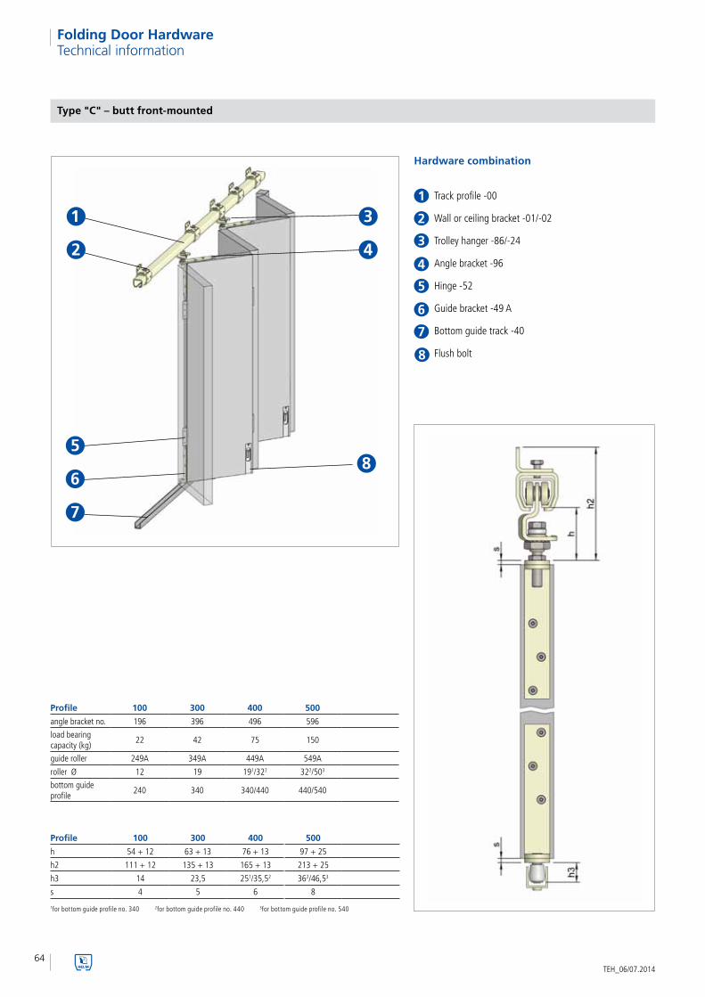
Type "A" – butt-enclosed
Hardware combination
Track profile -00
Wall or ceiling bracket -01/-02
Trolley hanger -86/-24
Angle bracket -94
Hinge -52
Guide roller -49
Bottom guide track -40
Flush bolt
1for bottom guide profile no. 340 2for bottom guide profile no. 440 3for bottom guide profile no. 540
Profile 100 300 400 500
h 54 + 12 63 + 13 76 + 13 97 + 25
h2 90 + 12 109 + 13 131 + 13 172 + 25
h3 14 23,5 251/362 32,52/46,53
s 4 5 6 8
Profile 100 300 400 500
angle bracket no. 194 394 494 594
guide roller 249 349 449 549
load bearing capacity (kg)
22 42 75 150
roller Ø 12 19 191/322 322/503
bottom guide profile
240 340 340/440 440/540

63
1
2
4
3
6
5
7
8
6
7
4
1
5
3
2
8
Fold
ing
Do
or
Har
dw
are
TEH_06/07.2014
Folding Door HardwareTechnical information
Type "B" – butt front-mounted
6
Track profile -00
Wall or ceiling bracket -01/-02
Trolley hanger -86/-24
Angle bracket -97 right or left
Hinge -52
Guide roller -50 right or left
Bottom guide track -40
Flush bolt
7
4
1
5
3
2
Hardware combination
1for bottom guide profile no. 340 2for bottom guide profile no. 440 3for bottom guide profile no. 540
Profile 100 300 400 500
h 54 + 12 63 + 13 76 + 13 97 + 25
h2 111 + 12 135 + 13 165 + 13 213 + 25
h3 18 28,5 29,51/382 372/46,53
s 4 5 6 8
Profile 100 300 400 500
angle bracket no. 197 397 497 597
load bearing capacity (kg)
22 42 75 150
guide roller 250 350 450 550
roller Ø 12 19 191/322 322/503
bottom guide profile
240 340 340/440 440/540
64
1
2 4
3
6
5
7
8
6
7
4
1
5
3
2
8
TEH_06/07.2014
Folding Door HardwareTechnical information
Type "C" – butt front-mounted
1for bottom guide profile no. 340 2for bottom guide profile no. 440 3for bottom guide profile no. 540
Hardware combination
Track profile -00
Wall or ceiling bracket -01/-02
Trolley hanger -86/-24
Angle bracket -96
Hinge -52
Guide bracket -49 A
Bottom guide track -40
Flush bolt
Profile 100 300 400 500
angle bracket no. 196 396 496 596
load bearing capacity (kg)
22 42 75 150
guide roller 249A 349A 449A 549A
roller Ø 12 19 191/322 322/503
bottom guide profile
240 340 340/440 440/540
Profile 100 300 400 500
h 54 + 12 63 + 13 76 + 13 97 + 25
h2 111 + 12 135 + 13 165 + 13 213 + 25
h3 14 23,5 251/35,52 362/46,53
s 4 5 6 8
65
Fold
ing
Do
or
Har
dw
are
TEH_06/07.2014
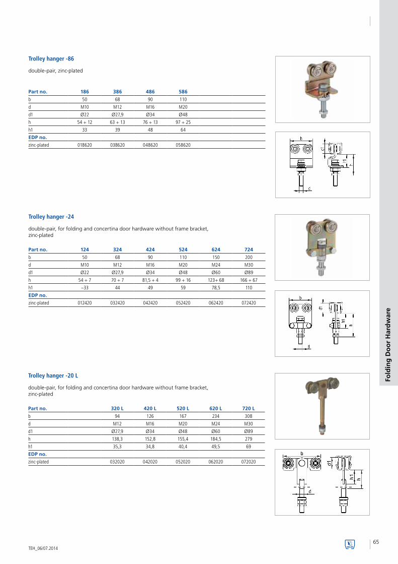
Part no. 186 386 486 586
b 50 68 90 110
d M10 M12 M16 M20
d1 Ø22 Ø27,9 Ø34 Ø48
h 54 + 12 63 + 13 76 + 13 97 + 25
h1 33 39 48 64
EDP no.
zinc-plated 018620 038620 048620 058620
Trolley hanger -86
double-pair, zinc-plated
Trolley hanger -24
double-pair, for folding and concertina door hardware without frame bracket, zinc-plated
Part no. 124 324 424 524 624 724
b 50 68 90 110 150 200
d M10 M12 M16 M20 M24 M30
d1 Ø22 Ø27,9 Ø34 Ø48 Ø60 Ø89
h 54 + 7 70 + 7 81,5 + 4 99 + 16 123+ 68 166 + 67
h1 ~33 44 49 59 78,5 110
EDP no.
zinc-plated 012420 032420 042420 052420 062420 072420
Trolley hanger -20 L
double-pair, for folding and concertina door hardware without frame bracket, zinc-plated
Part no. 320 L 420 L 520 L 620 L 720 L
b 94 126 167 234 308
d M12 M16 M20 M24 M30
d1 Ø27,9 Ø34 Ø48 Ø60 Ø89
h 138,3 152,8 155,4 184,5 279
h1 35,3 34,8 40,4 49,5 69
EDP no.
zinc-plated 032020 042020 052020 062020 072020

66TEH_06/07.2014
Folding Door HardwareSingle Parts
Trolley hanger -20 L
double-pair, for folding and concertina door hardware without frame bracket, zinc-plated
Part no. 321 L 421 L 521 L 621 L 721 L
b 94 126 167 234 308
d M12 M16 M20 M24 M30
d1 Ø27,9 Ø34 Ø48 Ø60 Ø89
h 138,3 151,8 154,4 190,5 279
h1 35,3 34,8 39,4 61 69
EDP no.
zinc-plated 032120 042120 052120 062120 072120
Part no. 194 394 494 594
Profile 100 300 400 500
b 20 30 35 40
d M10 M12 M16 M20
d1 4,8 5,9 7 8,4
h 124 158 210 260
I 124 158 200 255
l1 15 20 20 30
EDP no.
zinc-plated 019420 039420 049420 059420
Angle bracket -94
zinc-plated, for timber leaves, for screwing on or countersinking, with thread on the side
Angle bracket -97zinc-plated, for timber leaves, for screwing on or countersinking, with thread on the side
Part no. 197 397 497 597
Profile 100 300 400 500
b 20 30 35 40
d M10 M12 M16 M20
d1 4,8 5,9 7 8,4
h 124 158 210 260
I 124 158 200 255
b1 32 43 51 75
EDP no.
right 019720 039720 049720 059720
left 019721 039721 049721 059721

67
Fold
ing
Do
or
Har
dw
are
TEH_06/07.2014
Folding Door HardwareSingle Parts
Angle bracket -96
zinc-plated, for timber leaves, for screwing on or countersinking, with thread on the side
Part no. 196 396 496 596
Profile 100 300 400 500
b 20 30 35 40
d M10 M12 M16 M20
d1 4,8 5,4 7 8,4
h 120 165 223 260
I 130 160 219 280
l1 10 15 18 20
EDP no.
zinc-plated 019620 039620 049620 059620
Part no. 196 S 396 S 496 S 596 S 696 S 796 S
Profile 100 300 400 500 600 700
b 20 24 30 38 50 60
d M10 M12 M16 M20 M24 M30
h 8 11 15 20 25 30
I 100 100 120 140 150 180
l1 10 12 15,5 20 20 25
EDP no.
steel blank 019611 039611 049611 059611 069611 079611
Flange -96 S
in blank steel, for steel leaves, for welding on, with thread at the side
Hinge strap 320 BL
edged, without holes, with brass sleeves
Part no. 320 BL 420 BL 520 BL 620 BL
d 12 16 22 26
h 80 90 110 110
I 150 80 100 100
s 6 6 6 6
EDP no.
032042 042044 052044 062044
no. 196 S
no. 196 S
no. 396 S-796 S
no. 396 S-796 S

68TEH_06/07.2014
Folding Door HardwareSingle Parts
Guide roller -50
with flange joint and roller at the side, in combination with bottom guide profile no. 240-540, with plastic or brass roller
Part no. 250 350 450 550
bottom guide profile 240 340 340/440 440/540
b 20 30 35 40b1 32 43 41 75d Ø12 Ø19 Ø191 / Ø322 Ø322 / Ø49,53
h 138 181,5 233,51/2422 2892/298,53
h1 124 158 210 260I 124 158 200 255EDP no.plastic roller right 025060 035060 0450601 0550602
0450622 0550623
plastic roller left 025061 035061 0450611 0550612
0450632 0550633
brass roller right 025040 035040 0450401 0550402
0450422 0550423
brass roller left 025041 035041 0450411 0550412
0450432 0550433
1for bottom guide profile no. 340 2for bottom guide profile no. 440 3for bottom guide profile no. 540
Guide roller -49 A
with flange joint and roller at the side, in combination with bottom guide profile no. 340, 440 and 540, with plastic or brass roller
Part no. 249 A 349 A 449 A 549 A
bottom guide profile 240/240 K 340/340 K 340/440 K 440/540 K
b 20 30 35 40d Ø12 Ø19 Ø191 / Ø322 Ø322 / Ø49,53
h 142 188,5 2482/ 258,53 2962/ 306,53
h1 128 165 223 260I 130 160 219 280l1 10 15 18 20EDP no.plastic roller 024966 034966 0449661 0549662
0449672 0549673
brass roller 024946 034946 044946 054946044947 054947
1for bottom guide profile no. 340 2for bottom guide profile no. 440 3for bottom guide profile no. 540
Part no. 249 349 449 549
bottom guide profile 240 340 340/440 440/540
b 20 30 35 40
d 12 19 191/322 322/49.53
h 138 182 2351/2462 2962/3063
h1 124 158 210 260
I 124 158 200 255
l1 15 20 20 30
EDP no.
plastic roller 024960 034960 0449601 054960²
- - 0449652 0549653
brass roller 024940 034940 0449401 054940²
- 0449452 0549453
Guide roller -49
with angle bracket fixing and roller at the side, in combination with bottom guide profile no. 240-540 with plastic or brass roller
1for bottom guide profile no. 340 2for bottom guide profile no. 440 3for bottom guide profile no. 540

69
Fold
ing
Do
or
Har
dw
are
TEH_06/07.2014
Folding Door HardwareSingle Parts
Guide roller -20 F
zinc-plated, bottom guide roll with adjusting ring
Part no. 320 F 420 F 520 F 620 F 720 F
d Ø19 Ø32 Ø32 Ø49,5 Ø49,5
d1 Ø12 Ø16 Ø22 Ø26 Ø30
h 160 200 220 240 300
h1 136,5 169,5 189,5 200 258
EDP no.
brass roller 032041 042041 052041 062041 072041
Guide roller -49 S
with screw joint, zinc-plated or stainless steel with plastic or brass roller
Part no. 349 S 449 S 549 S
bottom guide profile 340 440 540
d 19 32 50
d1 M10 M16 M20
h 47,3 63 81
h1 32 42,5 52
EDP no.
plastic roller¹ 034962 044962 054962
plastic roller² 03496230 - -
brass roller¹ 034942 044942 054942
1screw joint zinc-plated 2screw joint stainless steel

70
A A A A BLÖ
TEH_06/07.2014
Concertina Door HardwareGeneral Information
HELM concertina door hardware
For door weights up to 500 kg with a single leaf width of 600-900 mm. A bottom guide track is not required.

71
1
24
3
5
4
1
5
3
2
Co
nce
rtin
a D
oo
r H
ard
war
e
TEH_06/07.2014
Concertina Door HardwareTechnical information
HELM concertina door
Hardware combination
Track profile -00
Ceiling soffit bracket -02
Trolley hanger -86/-24
Flange -93
Hinge -52
Profile 100 300 400 500
angle bracket no. 193 393 493 593
door weight (kg) 22 42 75 150
Profile 100 300 400 500
h 54 + 12 63 + 13 76 + 13 97 + 25
h2 90 + 12 109 + 13 131 + 13 172 + 25

72TEH_06/07.2014
Concertina Door HardwareSingle Parts
Part no. 186 386 486 586
b 50 68 90 110
d M10 M12 M16 M20
d1 Ø22 Ø27,9 Ø34 Ø48
h 54 + 12 63 + 13 76 + 13 97 + 25
h1 33 39 48 64
EDP no.
zinc-plated 018620 038620 048620 058620
Trolley hanger -86
double-pair, zinc-plated
Trolley hanger -24
double-pair, for folding and concertina door hardware without frame bracket, zinc-plated
Part no. 124 324 424 524 624 724
b 50 68 90 110 150 200
d M10 M12 M16 M20 M24 M30
d1 Ø22 Ø27,9 Ø34 Ø48 Ø60 Ø89
h 54 + 7 70 + 7 81,5 + 4 99 + 16 123+ 68 166 + 67
h1 ~33 44 49 59 78,5 110
EDP no.
zinc-plated 012420 032420 042420 052420 062420 072420
Part no. 193 393 493 593 693 793
Profile 100 300 400 500 600 700
b 20 24 30 38 50 60
d M10 M12 M16 M20 M24 M30
d1 6 5,3 6,8 7,5 11 11
h 8 11 15 20 25 30
I 100 160 210 264 350 500
EDP no.
zinc-plated 019320 039320 049320 059320 069320 079320
stainless steel 019330 039330 049330 059330 - -
Flange -93
zinc-plated or stainless steel, for timber leaves, for screwing on, with thread positioned in the centre

73
Co
nce
rtin
a D
oo
r H
ard
war
e
TEH_06/07.2014
Concertina Door HardwareSingle Parts
Guide roller 249 F
with flange joint and roller at the side, in combination with bottom guide profile no. 240 with plastic or brass roller
Part no. 249 F
bottom guide profile 240
b 20
d 12
d1 4.2
h 18
h1 14
I 90
EDP no.
plastic roller 024961
brass roller 024941
Part no. 349 F 449 F 549 F 649 F
bottom guide profile 340 340/440 440/540 540
b 24 30 38 50
d 19 191/322 322/49.53 49.5
d1 5.3 6.8 7.5 11
h 36 40¹/502 562/663 77
h1 25 25¹/352 362/463 52
I 160 210 264 350
EDP no.
plastic roller 034961 044961¹ 054961² 064961
- 0449642 0549643 -
brass roller 034941 044941¹ 054941² -
- 0449442 0549443 -
Guide roller -49 F
with flange joint and roller in the centre, in combination with bottom guide profile no. 340, 440 and 540 with plastic or brass roller
1for bottom guide profile no. 340 2for bottom guide profile no. 440 3for bottom guide profile no. 540

74
BAALÖ
A A BLÖ
A A A A BLÖ
A A ALÖ
TEH_06/07.2014
Folding Door Hardware and Concertina Door HardwareEnquiry Form
Required information:
Number of required installations:: _______________________________________ piece
Sliding door hardware: folding door installation
concertina door installation
number of leaves: ________ piece Type of track mounting. wall mounting
clear opening: ________ mm ceiling mounting
leaf thickness: ________ mm Type of installation one-group, movable to the right
door weight: ________ kg one-group, movable to the left two-group
Leaf material: timber
steel
type A type B type C
Folding door: Installation type “A“ Folding door: Installation type “C“Folding door: Installation type “B“
Concertina door
Required information for round the corner sliding doors
Company __________________________________________
Name __________________________________________
Street __________________________________________
Postcode/city __________________________________________
Telephone __________________________________________
Fax __________________________________________
E-mail __________________________________________
Contact person ________________________________________
Supply exclusively through specialised trade. Please indicate your specialist dealer if appropriate: ____________________________________
Woelm GmbH I Hasselbecker Str. 2- 4 I D - 42579 Heiligenhaus I Phone: + 49 (0) 20 56 - 18 - 0 I Telefax: + 49 (0) 20 56 - 18 - 21
Woelm Austria GmbH I Seewalchen 5a I A - 5201 Seekirchen I Phone: + 43 (0) 62 12 - 25 - 02 I Telefax: + 43(0) 62 12 - 69 - 95
Order Enquiry Date ________________

75
Ap
pen
dix
TEH_06/07.2014

76TEH_06/07.2014
Parallel Sliding-Stacking Hardware
Hardware for sliding stacking doors
Sliding stacking doors offer versatile solutions for room partitions and special applications in the field of sliding gates. The leaves are moved independently of each other into a parking station by means of an automatically changing switch, pivot switches or turning platforms.
The different installation situations resulting from this are depicted schematically on the next few Pages. The number and width of the leaves can be chosen according to the requirements and no bottom guide track is required. We are pleased to design individual installations. Please use the fax form on page 75 for your enquiries.
General Information
Profile 300 400 500 600
steel rollers 140 kg 240 kg 480 kg 960 kg
Max. permissible door weight

77
Para
llel S
lidin
g-S
tack
ing
Har
dw
are
TEH_06/07.2014
Parallel Sliding-Stacking Hardware
Installations with automatically changing switches
Notes:• automaticpivotingoftheleaves• norodsrequiredforoperatingtheswitches• fastmovingoftheleaves• profilesizesHELM300toHELM600
fig. 1
Sliding stacking door with HELM point switch right, various angles possible
fig. 2
Sliding stacking door with HELM point switch 90° right
General Information
fig. 3
Sliding stacking door with HELM point switch 90° right

78TEH_06/07.2014
Parallel Sliding-Stacking HardwareGeneral Information
fig. 1
In the area of the automatically changing switch the following installation dimensions are to be taken into account:
fig. 3
Automatically changing switch, 90° right
fig. 2
Profile: 300 400 500 600
r standard radius (mm) 630± 15 610± 15 605± 15 790± 15
r more radiuses (mm) 410 415
a1 (mm) 750 750 750 900
b (mm) 100 100 100 100
d (mm) 750 750 750 1000
e (mm) 40 40 50 50
intermediate piece

79
Para
llel S
lidin
g-S
tack
ing
Har
dw
are
TEH_06/07.2014
Parallel Sliding-Stacking Hardware
Installations with pivot switches
Notes:• max.seven-trackparkingstationpossible• switchoperationnecessaryforeachleafmovement• availableinprofilesizesHELM300toHELM700• differentleafwidthspossible
fig. 1
Diagram of a parking station with up to 4 tracks
fig. 2
Diagram of a parking station with 5 tracks (also 7 tracks possible)
Installation examples:

80TEH_06/07.2014
Parallel Sliding-Stacking Hardware
fig. 1
Installation dimensions pivot switch, triple right
Profile: 300 400 500 600 700
a1 (approx. mm) 1400 1400 1800 1800 2200
b (min. mm) 60 70 90 110 130
e (mm) 50 50 50 50 50
Pivot switch with remote control
General Information

81
Para
llel S
lidin
g-S
tack
ing
Har
dw
are
TEH_06/07.2014
Parallel Sliding-Stacking Hardware
Turning platform installations
Notes:• singleleavescanbepositionedinaminimumofspaceintheparkingstation• parkingstationswithparkingoptionononesideortwosides(comparefig.1+2)• switchoperationnecessaryforeachleafmovement• availableinprofilesizesHELM300toHELM600
fig. 1
Diagram of a parking station with parking option on one side
fig. 2
Diagram of a parking station with parking option on both sides
General Information
Installation examples:

82TEH_06/07.2014
Parallel Sliding-Stacking Hardware
Installation dimensions turning platform with TELEFLEX operation
Door packet – stacking region
Profile: 300 400 500 600
a1 (mm) 400 400 500 600
b (mm) 100 100 130 170
e * (mm) 35 35 35 35
Turning platform with TELEFLEX operation
fig. 3
General Information
Note:In case of the profiles HELM 300 to HELM 500 it is possible to choose between manual and electrical operation. In case of profile size HELM 600 only electrical operation is possible.
* manual operation

83
Ap
pen
dix
TEH_06/07.2014
Parallel Sliding-Stacking HardwareEnquiry Form
Installation types
fig. 1
fig. 2
fig. 3
fig. 4
fig. 5
fig. 6
Required information for round the corner sliding doors
Company __________________________________________
Name __________________________________________
Street __________________________________________
Postcode/city __________________________________________
Telephone __________________________________________
Fax __________________________________________
E-mail __________________________________________
Contact person ________________________________________
Supply exclusively through specialised trade. Please indicate your specialist dealer if appropriate: ____________________________________
For drawing up an offer a dimensioned floor plan of the installation situation is required.
Track mounting wall mounting ceiling mounting height-adjustable
Installation type ______________________ Leaf widths mm
Clear opening dimension ______________________ mm Leaf thickness _____________________ mm
Number of leaves ______________________ piece Leaf height _____________________ mm
Material _____________________ door weight _____________________ kg
Parking station area ______________________ mm
______________________
Woelm GmbH I Hasselbecker Str. 2- 4 I D - 42579 Heiligenhaus I Phone: + 49 (0) 20 56 - 18 - 0 I Telefax: + 49 (0) 20 56 - 18 - 21
Woelm Austria GmbH I Seewalchen 5a I A - 5201 Seekirchen I Phone: + 43 (0) 62 12 - 25 - 02 I Telefax: + 43(0) 62 12 - 69 - 95
Order Enquiry Date ________________
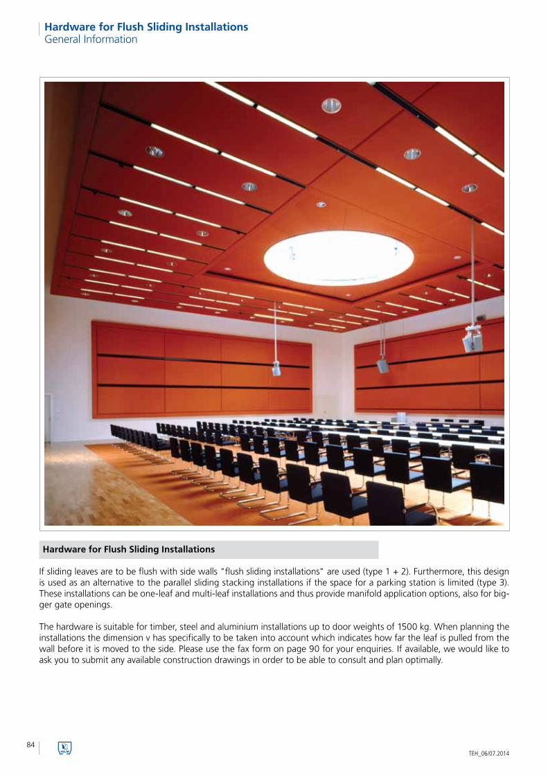
84TEH_06/07.2014
Hardware for Flush Sliding InstallationsGeneral Information
Hardware for Flush Sliding Installations
If sliding leaves are to be flush with side walls "flush sliding installations" are used (type 1 + 2). Furthermore, this design is used as an alternative to the parallel sliding stacking installations if the space for a parking station is limited (type 3). These installations can be one-leaf and multi-leaf installations and thus provide manifold application options, also for big-ger gate openings.
The hardware is suitable for timber, steel and aluminium installations up to door weights of 1500 kg. When planning the installations the dimension v has specifically to be taken into account which indicates how far the leaf is pulled from the wall before it is moved to the side. Please use the fax form on page 90 for your enquiries. If available, we would like to ask you to submit any available construction drawings in order to be able to consult and plan optimally.

85
Har
dw
are
for
Flu
sh S
lidin
g In
stal
lati
on
s
TEH_06/07.2014
Hardware for Flush Sliding Installations
Type 1
Type 2
Type 3
fig. 1
fig. 2
fig. 3
General Information
Benefits of a flush sliding installation:• effortless moving to the side• the full opening is freely accessible• no maintenance• simple mounting• easy hanging of doors or windows• side and height adjustment (precise adjustment of the door and window installation)• for timber, steel and aluminium designs

86
1
3
4
56
78
9
10
11
2
1
2
3
4
5
6
7
8
9
10
11
TEH_06/07.2014
Hardware for Flush Sliding InstallationsGeneral Information
Trolley hanger -86
Angle bracket -95
Angle bracket -94
Mounting part
Rail stop -00 P
Type 1 – installation example
Track profile
Gooseneck
Double wall mounting bracket -04 WD
Height-adjustable bracket -04
Ceiling bracket -02
Connection bracket -03
In case of type 1 the gate installation is pivoted on one side from the reveal and then moved to the side. It is crucial to note that the dimension v is limited to a maximum of 200 mm.

87
l
h
v
Har
dw
are
for
Flu
sh S
lidin
g In
stal
lati
on
s
TEH_06/07.2014
Hardware for Flush Sliding Installations
movable up to max. 200 mm in depth
fig. 1
Profile 100 300 400 500 600 700
max. door weight 60 kg 140 kg 240 kg 480 kg 960 kg 1500 kgdimension L (mm) 600 700 700 700 800 800dimension h (mm) 127+12 152+13 183+13 244+25 309+68 432+67dimension v up to 200 mm up to 200 mm up to 200 mm up to 200 mm up to 200 mm up to 200 mm
fig. 2
Mounting part Type 1

88
12
3
4
56
7
8
1
2
3
4
5
67
8
v
h
TEH_06/07.2014
Hardware for Flush Sliding InstallationsGeneral Information
Type 2 – installation example
fig. 1
Track profile
Wall mounting bracket -04 W
Height-adjustable bracket -04
Ceiling bracket -02
Rail stop -00 P
Flange -93
Trolley hanger -86
Trolley hanger -29
Profile 100 300 400 500 600 700
max. door weight 60 kg 140 kg 240 kg 480 kg 960 kg 1500 kgdimension h (mm) 119+10 145+20 175+20 232+17 297+17 392+85dimension v variable variable variable variable variable variable
Installation cross-section
fig. 2Type 2 is specifically used when the installation has to be pulled more than 200 mm from the wall. For this the leaf is pulled off in parallel to the wall, dimension v is variable.

89
1
2
3
4
5
67
8
v
h
Har
dw
are
for
Flu
sh S
lidin
g In
stal
lati
on
s
TEH_06/07.2014
Hardware for Flush Sliding Installations General Information
Type 3 – installation example
fig. 1
Track profile
Gooseneck
Connection bracket -03
Double wall mounting bracket -04 WD
Wall mounting bracket -04 W
Height-adjustable bracket -04
Trolley hanger -86
Flange -93
fig. 2
Dimension “v“ in case of protruding track profile
Profile 100 300 400 500
max. door weight 60 kg 140 kg 240 kg 480 kgdimension h 82+12 98+13 119.5+13 157+25dimension v variable variable variable variable
In case of double doors up to 480 kg door weight and limited space for the parking station type 3 is chosen. The mode of operation is similar to a parallel sliding stacking installa-tion, however, in contrast to the latter the pivoting range is shifted into the door opening for lack of space.
1
2
3
4
5
6
7
8

90TEH_06/07.2014
Hardware for Flush Sliding InstallationsEnquiry Form
Type ______________________ (see filg. 1-3)
Leaf widths ______________________ mm Leaf thickness _____________________
door weight ______________________ kg dimension v _____________________ mm
Type manuell
Track mounting wall mounting ceiling mounting
height-adjustable
In order to be able to process your enquiry we require a sketch with the above-mentioned details.
fig. 1
fig. 2
fig. 3
timber steelLeaf material
Required information for round the corner sliding doors
Company __________________________________________
Name __________________________________________
Street __________________________________________
Postcode/city __________________________________________
Telephone __________________________________________
Fax __________________________________________
E-mail __________________________________________
Contact person ________________________________________
Supply exclusively through specialised trade. Please indicate your specialist dealer if appropriate: ____________________________________
Order Enquiry Date ________________
Woelm GmbH I Hasselbecker Str. 2- 4 I D - 42579 Heiligenhaus I Phone: + 49 (0) 20 56 - 18 - 0 I Telefax: + 49 (0) 20 56 - 18 - 21
Woelm Austria GmbH I Seewalchen 5a I A - 5201 Seekirchen I Phone: + 43 (0) 62 12 - 25 - 02 I Telefax: + 43(0) 62 12 - 69 - 95

91
Ap
pen
dix
TEH_06/07.2014

92TEH_06/07.2014
AccessoriesPull Handles and Flush Handles
Part no. 256
Profile
b 30
b1 20
h 43
I 180
s 7
EDP no.
aluminium 0256.50
aluminium, silver anodised
Standard type
steel
silver stove enamelled .02
black stove enamelled .03
zinc-plated .06
dark brown stove enamelled .10
coloured plastic-coated .70
aluminium machined according to E 5
KWS 1 silver anodised .31
KWS 2 nickel silver anodised .32
KWS 3 gold anodised .33
brushed stainless steel effect anodised .35
KWS 5 dark bronze anodised .37
stainless steel
brushed .82
polished .83
unit 10 pieces
piece weight
steel 0.260 kg
aluminium 0.080 kg
stainless steel 0.260 kg
5208..90 x 200 mm
Note:For mounting sufficient depth for flush is required.
Example for order
Piece Part no. Design
... Piece 5207 .02
Note: This is only a very small excerpt of our extensive range of KWS pull handles and flush handles.
Handle 256 LM

93
Flush Handles
Acc
esso
ries
TEH_06/07.2014
Accessories
Example for order
Piece Part no. Design Cut-out Distance right/left
... Piece 5055 .02 profile cylinder 72 R
Standard type
steel/aluminium
pull of steel with ring
of aluminium
silver stove enamelled .02
black stove enamelled .03
dark brown stove enamelled .10
coloured plastic-coated .70
aluminium machined according to E 5
pull of aluminium with ring
of aluminium
KWS 1 silver anodised .31
KWS 2 nickel silver anodised .32
KWS 3 gold anodised .33
brushed stainless steel effect anodised .35
KWS 5 dark bronze anodised .37
unit 2 pieces
piece weight
steel/aluminium 0.440 kg
aluminium 0.230 kg
with flush, fixed slewable folding ring handle, pin of the pin part firmly riveted
Cut-outwith or without cut-out, e. g. pro-file cylinder, key, KABA, smallest distance for profile cylinder cut-out = 55 mmbiggest distance for profile cylin-der cut-out = 72 mm
This folding ring flush handle can-not be used in pairs or in combi-nation with a door handle or door knob.
This door hardware is available in similar form in stainless steel: see 5061.. 5062.. and 5064.. 5065..
Note:For mounting sufficient depth for flush is required.
Fig. shows right door hardware.
5055
5056
5058
5059
170 x 170 with 8 mm hole
170 x 170 with 8 mm pin
170 x 170 with 9 mm hole
170 x 170 with 9 mm pin

94TEH_06/07.2014

95TEH_06/07.2014

The technical specifications are up-to-date. We reserve the right to make modifications with regard to design and styling which serve the purpose of technical improvement. We appreciate your understanding that we assume no liability for any typing errors or any other errors. The reproduction of this document, in extracts or complete, is not permitted without our express written permission.
Part no. TEH_06/07.2014This catalogue supersedes all previous catalogues.
TEK_0102 TEK_0308 TEK_0506
TEK_0407
TEH_01 TEH_02H TEH_02G
TEH_02D TEH_06 TEH_09
TEH_11 TEH_12 TEH_40
HELM Range
TEH_01 Hardware for Sliding Wardrobe Doors
TEH_02H Hardware for Sliding Doors (Timber)
TEH_02G Hardware for Sliding Doors (Glass)
TEH_02DDesign Hardware forSliding Doors (Timber and Glass)
TEH_06 Hardware for Sliding Gates
TEH_09 Hardware for Gateway Gates
TEH_11 Hardware for Curtains and Tarpaulins
TEH_12Safety Equipment against Falls from a Height (PSE)
TEH_40 Hardware for Sliding Shutters
KWS Range
TEK_0102 Door Holders and Door Stops
TEK_0308 Pull Handles, Door Handles and Accessories
TEK_0506 Flush Handles and Locks
TEK_0407Hardware for Handrails, Floor Rails,Coat Racks and Toilet Partition Walls
Woelm GmbHHasselbecker Str. 2- 4D - 42579 HeiligenhausPhone: + 49 (0) 20 56 - 18 - 0Telefax: + 49 (0) 20 56 - 18 - [email protected]
Woelm Austria GmbHSeewalchen 5aA - 5201 SeekirchenPhone: + 43 (0) 62 12 - 25 02Telefax: + 43 (0) 62 12 - 69 [email protected]