
Rail Accident Report - gov.uk · Rail Accident Report Collision between train and buffer stops at...
36
Report 26/2006 December 2006 Rail Accident Report Collision between train and buffer stops at Sudbury 27 January 2006
Transcript of Rail Accident Report - gov.uk · Rail Accident Report Collision between train and buffer stops at...
Report 26/2006December 2006
Rail Accident Report
Collision between train and buffer stops at Sudbury27 January 2006

This investigation was carried out in accordance with:
l the Railway Safety Directive 2004/49/EC;l the Railways and Transport Safety Act 2003; and l the Railways (Accident Investigation and Reporting) Regulations 2005.
© Crown copyright 2006 You may re-use this document/publication (not including departmental or agency logos) free of charge in any format or medium. You must re-use it accurately and not in a misleading context. The material must be acknowledged as Crown copyright and you must give the title of the source publication. Where we have identified any third party copyright material you will need to obtain permission from the copyright holders concerned. This document/publication is also available at www.raib.gov.uk.
Any enquiries about this publication should be sent to:
RAIB Email: [email protected] Wharf Telephone: 01332 253300Stores Road Fax: 01332 253301 Derby UK Website: www.raib.gov.ukDE21 4BA
This report is published by the Rail Accident Investigation Branch, Department for Transport.

Rail Accident Investigation Branchwww.raib.gov.uk
� Report 26/2006December 2006
Contents
Introduction 5
Summaryofthereport 6
Key facts 6
Conclusions 7
Recommendations 7
TheAccident 8
Summary of events 8
The line from Sudbury to Marks Tey 9
The parties involved 9
The track 10
The train 11
Events preceding the Accident 15
Events during the Accident 16
Events immediately after the Accident 17
TheInvestigation 19
Evidence 19
Analysis 20
The train 20
Track 23
Train driving 25
Severity of collision 28
Conclusions 29
Actionsalreadytakenorinprogress 30
Collision between train and buffer stops atSudbury, 27 January 2006

Rail Accident Investigation Branchwww.raib.gov.uk
� Report 26/2006December 2006
Recommendations 31
Appendices 32
Appendix A: Glossary of abbreviations and acronyms 32
Appendix B: Glossary of terms 33
Appendix C: References 35

Rail Accident Investigation Branchwww.raib.gov.uk
� Report 26/2006December 2006
1 The sole purpose of a Rail Accident Investigation Branch (RAIB) investigation is to prevent future accidents and incidents and improve railway safety.
2 The RAIB does not establish blame, liability or carry out prosecutions.3 In this report all references to One Railway, part of the National Express Group, are shown
as ‘one’.4 Access was freely given by ‘one’ to staff, data and records.5 In this report the masculine form of address (him, his, etc.) is used for both male and
female.6 Appendices at the rear of this report contain information explaining the following: l acronyms and abbreviations are explained in the Glossary at Appendix A; and l certain technical terms (shown in italics within the body of this report) are explained in
the Glossary at Appendix B.
Introduction

Rail Accident Investigation Branchwww.raib.gov.uk
6 Report 26/2006December 2006
Keyfacts7 On 27 January 2006 at 18:27 hrs a passenger diesel train, reporting number 2T28, ran into
the buffer stops at Sudbury Station. It was formed of two coach unit 156422, comprising vehicles 57422 (leading) and 52422 (trailing). Both the train and the station were operated by ‘one’. The collision occurred at about 6.4 mph (10.2 km/h) as the train was braking to a stand. Approximately 100 passengers were on board at the time; a number of them received minor injuries as a result of falls caused by the rapid deceleration of the collision. First aid attention was given by other passengers and shortly afterwards by paramedics who were called to the scene. One passenger sustained suspected fractured ribs. No passengers were conveyed to hospital.
8 Sudbury Station is at the end of a single track branch line from Marks Tey (see Figure 1). It has a single platform face capable of berthing a two coach train; the single track is devoid of any points or signalling. TrainProtectionandWarningSystem (TPWS) loops, enforcing a 10 mph (16 km/h) speed limit, are provided at the entry to the platform area. The buffer stops are of traditional construction using bullhead rail; no retardation mechanism is fitted nor does the design of buffer stops provide any capability for absorbing the energy of a collision.
Summary of the report
Figure1:ExtractfromOrdnanceSurveymapshowinglocationofincident
Location of incident
© Crown Copyright. All rights reserved. Department for Transport 1000202�7 2006
Rail Accident Investigation Branchwww.raib.gov.uk
7 Report 26/2006December 2006
Conclusions9 The immediate cause of the accident was that the brakes of the train were not applied in a
timely and appropriate manner.
Recommendations10 Two recommendations have been made to improve the safety of trains entering Sudbury
Station (see Paragraph 118). One of these is directed at Network Rail and the other is directed at ‘one’, but has possible applications for other train and freight operating companies.

Rail Accident Investigation Branchwww.raib.gov.uk
� Report 26/2006December 2006
Summaryofevents
The Accident
11 On 27 January 2006 at 18:27 hrs a passenger diesel train, reporting number 2T28, ran into the buffer stops at Sudbury Station (Figure 2). It was formed of two coach unit 156422, comprising vehicles 57422 (leading) and 52422 (trailing). Both the train and the station were operated by ‘one’. The collision occurred at about 6.4 mph (10.2 km/h) as the train was braking to a stand. Approximately 100 passengers were on board at the time; a number of them received minor injuries as a result of falls caused by the rapid deceleration of the collision. Minor first aid attention was given by other passengers and shortly afterwards by paramedics who were called to the scene. One passenger sustained suspected fractured ribs. No passengers were conveyed to hospital.
Figure2:156422atthebufferstopsatSudburyimmediatelyafterthecollision
Rail Accident Investigation Branchwww.raib.gov.uk
� Report 26/2006December 2006
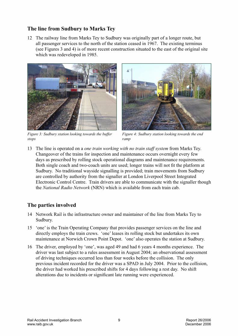
ThelinefromSudburytoMarksTey12 The railway line from Marks Tey to Sudbury was originally part of a longer route, but
all passenger services to the north of the station ceased in 1967. The existing terminus (see Figures 3 and 4) is of more recent construction situated to the east of the original site which was redeveloped in 1985.
Figure3:Sudburystationlookingtowardsthebufferstops
Figure4:Sudburystationlookingtowardstheendramp
13 The line is operated on a onetrainworkingwithnotrainstaffsystem from Marks Tey. Changeover of the trains for inspection and maintenance occurs overnight every few days as prescribed by rolling stock operational diagrams and maintenance requirements. Both single coach and two-coach units are used; longer trains will not fit the platform at Sudbury. No traditional wayside signalling is provided; train movements from Sudbury are controlled by authority from the signaller at London Liverpool Street Integrated Electronic Control Centre. Train drivers are able to communicate with the signaller though the NationalRadioNetwork(NRN) which is available from each train cab.
Thepartiesinvolved14 Network Rail is the infrastructure owner and maintainer of the line from Marks Tey to
Sudbury. 15 ‘one’ is the Train Operating Company that provides passenger services on the line and
directly employs the train crews. ‘one’ leases its rolling stock but undertakes its own maintenance at Norwich Crown Point Depot. ‘one’ also operates the station at Sudbury.
16 The driver, employed by ‘one’, was aged 49 and had 6 years 4 months experience. The driver was last subject to a rules assessment in August 2004; an observational assessment of driving techniques occurred less than four weeks before the collision. The only previous incident recorded for the driver was a SPAD in July 2004. Prior to the collision, the driver had worked his prescribed shifts for 4 days following a rest day. No shift alterations due to incidents or significant late running were experienced.

Rail Accident Investigation Branchwww.raib.gov.uk
10 Report 26/2006December 2006
Thetrack17 The track in the platform at Sudbury comprises of 95 lb Bullhead rail held in cast iron
chairs with wooden keys on softwood sleepers. The rail heads have rumblestrip welds added to them (Figure 5); these ensure a good electrical contact between the rail and wheel for trackcircuit purposes. Rumble strips are commonly used where the train service is insufficient to ensure that rust, detritus and contaminants do not build up on the surface of the rail and thus inhibit traindetection. Although the branch is operated on the single train principle, confirmation has to be received by the signalman that the train has berthed at Sudbury before authority is issued for it to depart for Marks Tey. The track circuit at Sudbury, and hence the rumble strips, are provided for this purpose.
18 Certain parts of the rumble strips at Sudbury are nearing the end of their life. Along the length of platform track various examples of defect were found:
l flattened weld; l worn down weld with an unusual triangular wheel contact pattern with the normal head
of the rail; l spalling of the weld from the head of the rail. Examples are shown in Figures 5 to 7.19 Some time prior to the incident, Network Rail had started work to replace the welds.
This involved grinding the weld off the head of the rail, grinding out any corrosion from spalling, and re-profiling the head prior to laying down a new zigzag weld pattern. Some parts of the rail head were already awaiting the attention of specialist welders who would apply new weld strips. Figure 8 shows a section of ground rail head.
Figure5:TrackinSudburyplatform.Exampleofrailheadwithrumblestrip
Figure6:TrackinSudburyplatform.Exampleofspallingofrumblestrip

Rail Accident Investigation Branchwww.raib.gov.uk
11 Report 26/2006December 2006
Figure8:TrackinSudburyplatform.Exampleofsmoothrailhead
Figure7:TrackinSudburyplatform.Exampleofwornrumblestripsandtriangularrailheadcontact
20 TPWS loops are fitted between the rails on the approach to the buffer stops just outside the platform. The trigger loop is located at 60.75 m from the buffers, a distance which is compliant with the Network Rail standard. The two loops are separated by a distance appropriate to enforce a 10 mph (16 km/h) approach speed.
Thetrain21 The Class 156, also called a Super-Sprinter, is a 2-coach unit typical of many operating
secondary services over the Network Rail infrastructure. ‘one’ operates these trains with 2 crew members; a driver and a conductor.
22 The Class 156, first introduced in 1988, was built by Metro-Cammell in Birmingham to a concept design by British Rail. The unit is gangwayed throughout, thus permitting people to move through a train comprising one or more units. The driving cab, which extends across the whole front of the train, can be closed off from the vestibule by a door when it is in use by a driver or conductor. The left hand part of the cab (which contains the driving controls) may be closed off from public access when the gangway connection is in use for access to an adjacent unit. Because only 2-coach trains can be used on the Sudbury service, the doors between the driving cabs and the vestibules were kept closed.
23 The Class 156 incorporates many parts and design features that are common to other classes of diesel and electric trains. Each coach is diesel powered with the traction drive to the inner axle of each bogie provided by a hydraulic transmission. Cast iron brake blocks act upon the treads of the each wheel. There is a brake cylinder for each wheel.
24 The train is not fitted with wheelslide equipment that prevents the wheels locking during braking. The train is fitted with wheel slip equipment that prevents the wheels losing adhesion and rotating too quickly whilst traction power is applied.
25 A forward and aft brake control handle is situated on the left hand side of the driver’s desk. It comprises a five position cam operated switch. The masterswitch and power controller are located on the right.
26 The 3-step Westcode braking system is fitted to the class 156. It is an electrically controlled brake which functions on the ‘Energise-to-Release’ basis. Braking commands are transmitted down the train using four wires. The train brakes are automatically applied if the electrical circuit is broken for any reason.

Rail Accident Investigation Branchwww.raib.gov.uk
12 Report 26/2006December 2006
Figure9:Diagramofcontroldeck
Figure10:Brakecontrolhandle

Rail Accident Investigation Branchwww.raib.gov.uk
1� Report 26/2006December 2006
27 With the brake control handle pulled fully back the brakes are in the RELEASE condition, EMERGENCY is with the handle pushed fully forward. STEPS 1, 2 and 3 are between these two positions. Under tare (no load) conditions STEP 1 brake equates approximately to 1 bar brake cylinder pressure, STEP 2 equates to approximately 2 bar pressure and STEP 3 equates to approximately 3 bar pressure. Load weighing proportionately increases the brake cylinder pressure by up to 50 % as the passenger load increases.
28 When the EMERGENCY position is selected, the electrical circuit to the brake controller, the train command wires for the brakes and the brakedistributors are broken in both the feed and return wires. This ensures that there is virtually no possibility of releasing the brakes due to an electrical system defect.
29 The steps of the Westcode brake are controlled by two wires (23 and 24) energised through cam operated micro-switches on the brake controller. A third wire (25) called the Brake Continuity Wire, interlocks the brake system with other train systems and provides the electrical feed to wires 23 and 24. Wire 25 is de-energised in emergency braking. The Brake Negative wire carries the return current; it is disconnected when the brake controller is moved to the emergency position. The logic table for the energisation of the brake wires is shown in Figure 11.
Brakecylinderpressure(bar)Positionofbrakecontrolhandle Trainwiresenergised
Tare(No load)
Fully Loaded
RELEASE 23 24 25 0 0
STEP 1 - 24 25 1 1.5
STEP 2 23 - 25 2 3
STEP 3 - - 25 3 4.5
EMERGENCY - - - 3 4.5Figure11:Brakesystemfunctions
30 The train was fitted with Arrowvale On-TrainMonitoringRecorders(OTMRs) in both cabs. Both were in working order and were logging data about the trip. These devices record the condition of controls and functions within the train for later analysis. For the braking function, the OTMR records the energisation of train wires; it does not record the position of the brake control handle.
31 The energisation of the train wires goes through a specific sequence when the brake handle is moved from Release to Emergency. The steady state sequence is shown in tabular form in Figure 11. The change of state sequence for the energisation of the train wires is shown in Figure 14.

Rail Accident Investigation Branchwww.raib.gov.uk
1� Report 26/2006December 2006
Figure12:ExtracteddatafromOTMRtraceof57422
Figure13:OTMRtracefrom57422

Rail Accident Investigation Branchwww.raib.gov.uk
1� Report 26/2006December 2006
Eventsprecedingtheaccident32 The driver’s previous shift ended at about 01:00 hrs. After a short journey home (10
minutes) and a restful night the driver woke up at around 08:30 hrs. The day was spent on household activities.
33 The driver booked on early at 17:15 hrs in Colchester depot following a short journey to work. There were no issues in the latenoticecase or other matters that needed attention. Following a brief conversation with colleagues in the mess room, the driver walked to Colchester station to meet the conductor. They both travelled as passengers to Marks Tey. There, the driver had a cup of tea whilst waiting approximately 20 minutes before the arrival of the shuttle train to Sudbury. This was a similar pattern to that of the previous two days when the driver worked the same shift pattern.
34 Unit 156422 had been diagrammed to work the service on the Sudbury branch. After it arrived at Marks Tey the driver immediately took over the driving duties. The driver of the incoming service had not experienced any defect with the train, either in the form of driving controls or with other cab equipment such as heaters, ventilation, cab windows and seat. No difficulties had been experienced with adhesion or braking at Sudbury or elsewhere on the line, and no other problems had been evident. As was common working practice the incoming driver went to the Sudbury end of the train and opened up the cab controls before handing over the train to the relieving driver.
35 The driver and conductor were scheduled to work two round trips on the Sudbury branch that evening. This train, running number 2T28, was timetabled to leave Marks Tey at 18:05 hrs calling at Chapel & Wakes Colne, Bures and Sudbury. Its departure was delayed by approximately 3 minutes due to the late arrival of the connecting service from London.
36 The temperature for this part of Suffolk had remained near freezing point all day. In the late afternoon and early evening there had been recent light showers of snow that had not settled on the ground. It was dark, but visibility was otherwise good. These weather conditions had not made any impact on the train service.
37 The train experienced an uneventful journey from Marks Tey, stopping at the intermediate stations en route to Sudbury. Prior to each stop the conductor, who had been sitting in the second man’s seat in the leading cab, left for the adjacent passenger vestibule to supervise platform duties.
TRAIN WIRE23
TRAIN WIRE24
BRAKECONTINUITY
RELEASE EMERGENCYSTEP 1 STEP 2 STEP 3Energised
Energised
Energised
De-energised
De-energised
De-energised
Figure14:Diagramshowingtrainwirelogicforbrakesystem

Rail Accident Investigation Branchwww.raib.gov.uk
16 Report 26/2006December 2006
38 The 68 m long platform at Bures can accommodate 3 coaches; unusually the driver legitimately decided to stop at the very end of the platform (ie nearer to Sudbury). At both intermediate stations (Chapel & Wakes Colne and Bures) the train was brought to a gentle halt.
39 The train slowed for the Permanent Speed Restriction (PSR) of 35 mph (56 km/h) at Great Cornard crossing and later for the 20 mph (32 km/h) PSR at Ladybridge crossing. On the approach to the platform, and in good time for the station stop, the conductor moved from a position in the front drivers cab to a position in the vestibule, ready to open the doors. Some passengers also began to arise from their seats and to make their way towards the vestibules. The train then braked to less than 10 mph (16 km/h) at the beginning of Sudbury platform in order to pass over the TPWS over-speed loops protecting the terminal platform track. No TPWS intervention of the brake occurred.
40 The platform at Sudbury was damp, but there were no puddles or settled snow on the ground; due to the darkness it is not known if the rails were wet. The temperature was near freezing point.
41 The Sudbury buffer stop lights were correctly illuminated, and remained so after the collision.
Eventsduringtheaccident42 The OTMR shows that the train decelerated gently to about 6.4 mph (10.2 km/h) at the
entry to the platform, followed by a period of coasting with the brake handle maintained in the OFF position. The train speed rose to about 7.6 mph (12.2 km/h) during this coasting period due to the slight downward gradient. The driver recollects the following:
l STEP 1 was selected in Sudbury platform but the brake did not seem to perform as it should do.
l OFF was then briefly selected. l STEP 1 was re-selected but no brake effort was obtained. l STEP 3 braking was selected when the train was very close to the buffer stops, followed
almost immediately by EMERGENCY. 43 The OTMR records a different approach pattern from the driver’s recollection: STEP 1
braking was selected only once when part way down the platform. EMERGENCY was selected, after momentarily passing through STEPS 2 and 3, almost immediately prior to the impact. This sequence of brake demands did not decelerate the train sufficiently to stop it from hitting the buffers at slow speed. The speed of the initial impact could not be exactly determined from the OTMR records, however the collision probably occurred at no more than 6.4 mph (10.2 km/h) (see paragraph 99).
44 The collision significantly damaged the buffer stops which suffered severe bending and the fracture of one of the cross bars. The train suffered damage to the obstacle detector, coupler and gangway connection.

Rail Accident Investigation Branchwww.raib.gov.uk
17 Report 26/2006December 2006
45 The rapid deceleration in train speed caused a number of passengers to loose their balance and to fall forwards, either on to the floor or on to internal coach furniture, seat backs, vestibule luggage racks or doorway edges. Minor injuries of bruising and abrasions were sustained as a result. One passenger sustained suspected fractured ribs. No reports about injuries caused by falling or moving luggage, pushchairs or bicycles were received immediately after the accident. No life threatening injuries occurred, however at least one passenger has reported some long term physical effects, some others have reported a fear of travelling by train or on the branch line.
Eventsimmediatelyaftertheaccident46 Immediately after the collision the driver shut down the control desk and remained in the
driving seat in order to regain composure. The conductor initially glanced into the cab and having confirmed that the driver was not injured, moved back to the vestibule and opened the train doors. A short time later the driver opened the door from the cab and moved into the vestibule area, where, on being asked by the conductor what had happened, indicated that the brakes had failed. The train lights had tripped out at the time of the collision and the driver returned to the cab in order to switch them back on. The driver took the control key with him when finally leaving the cab.
Figure15:Damagetobufferstopwith57422initsfinal position
Figure16:Damageto57422(left-handside) Figure17:Damageto57422(right-handside)

Rail Accident Investigation Branchwww.raib.gov.uk
1� Report 26/2006December 2006
47 Whilst in the vestibule, the driver apologised to several passengers about what had happened, mentioning to them that the brakes seemed to have failed.
48 The driver then told the conductor that he would inform the signaller about the incident; this was done by using the platform telephone located adjacent to the far end of the train. The signaller instructed the driver not to move the train and to remain with it until instructed otherwise. The driver then went into the cab furthest from the buffer stops and opened up the control desk in order to keep the engines running for heating and lighting. This was in compliance with normal procedures issued by ‘one’.
49 When observed later in the evening the leading end (ie that closest to the buffer stops) was displaying (red) tail lights and the headlights were switched off. The destination blind showed SUDBURY. There is no certainty when the lights were changed. This could have been done when the driver closed down the control desk, or it is possible that it was done later. The tail-lights at the end of the train furthest from the buffer stops were illuminated when the control desk at that end of the train was opened up; they were left in that state.
50 Whilst the driver was at the end of the train furthest from the buffer stops, the conductor initially started to take names and contact details from some of the passengers. The conductor then started to call the emergency services but was informed by a member of the public that someone had already done so. The conductor then decided to walk through the train to check if any passengers had suffered any serious injuries, rather than take names and addresses. During the walk through the train, an injured and distressed female passenger was found lying on the floor receiving attention from another passenger. The conductor stayed with a male passenger who was found with bad bruising on his head and over his left eye until the ambulance personnel arrived after a few minutes. The conductor then went to find the driver who was sitting with a passenger in the saloon of the coach furthest from the buffer stops. This passenger was a railwayman with approximately 30 years service as a driver and then as a manager; he stayed with the driver for about 45 minutes helping him overcome the shock of the incident.
51 Subsequently the Fire Brigade, civil police, British Transport Police (BTP), the ‘one’ Driver Manager, the Network Rail Railway Incident Officer (RIO) and a rolling stock fitter arrived. A number of passengers, thought to be about 5 or 6, received attention from the ambulance crew, but all declined a visit to hospital.
52 The driver was later subject to a drugs and alcohol test at ‘one’s’ Colchester depot.53 There were 8 or 9 people waiting on the platform at Sudbury, mostly around the waiting
shelter, who directly witnessed the collision, or its immediate aftermath. Following the collision, the services on the Sudbury branch were suspended until the afternoon of the following day.

Rail Accident Investigation Branchwww.raib.gov.uk
1� Report 26/2006December 2006
54 The investigation was undertaken by two RAIB inspectors.
Evidence55 The investigation used the following sources of information: l inspection of the track at Sudbury; l testing of the TPWS loops at Sudbury; l inspection of the train at both Sudbury and later at Norwich Crown Point Depot; l testing of the train’s braking system; l reviews of train documentation from ‘one’; l interviews with the staff involved; l information provided by passengers and platform witnesses; l analysis of the OTMRs; l analysis of rail head and wheel tread swabs; l measurements of the rail head frictional coefficient.
The Investigation

Rail Accident Investigation Branchwww.raib.gov.uk
20 Report 26/2006December 2006
56 No similar accidents have occurred since the opening of the new station.
ThetrainConditions in the cab57 It was the practice that many conductors on the Sudbury service travelled in the leading
cab when they had no other duties to perform. This is in contravention of Rule Book Module TW1 section 5 ‘Travelling in Driving Cabs’. Like others that week, very little conversation passed between the two members of staff on the trip that ended in the collision. Long before the final approach to Sudbury platform the conductor had left the cab. Distraction from a second person in the cab has thus been discounted.
58 After the conductor had left the cab the connecting door was closed. Any possible distractions from light ingress from the vestibule, conversations between passengers, or sounds from radios or personal stereos have thus been discounted.
59 There is no evidence to suggest that the driver had been engaged in activities such as eating or reading that would divert his attention away from driving. The possibility of some form of direct distraction or refocusing of attention away from his driving duties has thus been discounted.
60 There is no evidence to indicate that environmental conditions in the cab contributed to the collision. With adequate time prior to departure from Marks Tey, the driver had satisfactorily set the seat position and the heaters. The driver confirmed that all features and equipment in the cab were in an acceptable condition and working adequately, as confirmed by the previous driver. The possibility of discomfort or distraction due to some defective item of equipment has thus been discounted.
General condition61 The maintenance records of the train have showed a normal pattern of maintenance with
no reports or defects that would influence the traction and braking performance. The previous comprehensive B6 examination occurred on 22 December 2005. This included a check on the brake controller and the brakeapplicationtimes. The less comprehensive A examination occurred on 21 January 2006. Both the A and B examinations included a check on the condition and wear on the brake blocks. Refuelling and minor checks were undertaken on 25 January 2006. At the time of the accident the defect cards in the cabs did not record any problem associated with the brakes or electrical supplies that could have had an affect on the braking of the train.
Analysis
Rail Accident Investigation Branchwww.raib.gov.uk
21 Report 26/2006December 2006
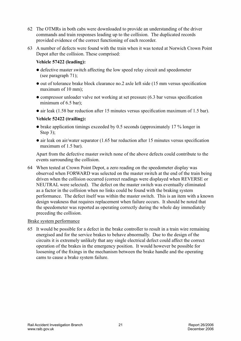
62 The OTMRs in both cabs were downloaded to provide an understanding of the driver commands and train responses leading up to the collision. The duplicated records provided evidence of the correct functioning of each recorder.
63 A number of defects were found with the train when it was tested at Norwich Crown Point Depot after the collision. These comprised:
Vehicle57422(leading): l defective master switch affecting the low speed relay circuit and speedometer
(see paragraph 71); l out of tolerance brake block clearance no.2 axle left side (15 mm versus specification
maximum of 10 mm); l compressor unloader valve not working at set pressure (6.3 bar versus specification
minimum of 6.5 bar); l air leak (1.58 bar reduction after 15 minutes versus specification maximum of 1.5 bar). Vehicle52422(trailing): l brake application timings exceeded by 0.5 seconds (approximately 17 % longer in
Step 3); l air leak on air/water separator (1.65 bar reduction after 15 minutes versus specification
maximum of 1.5 bar). Apart from the defective master switch none of the above defects could contribute to the
events surrounding the collision.64 When tested at Crown Point Depot, a zero reading on the speedometer display was
observed when FORWARD was selected on the master switch at the end of the train being driven when the collision occurred (correct readings were displayed when REVERSE or NEUTRAL were selected). The defect on the master switch was eventually eliminated as a factor in the collision when no links could be found with the braking system performance. The defect itself was within the master switch. This is an item with a known design weakness that requires replacement when failure occurs. It should be noted that the speedometer was reported as operating correctly during the whole day immediately preceding the collision.
Brake system performance65 It would be possible for a defect in the brake controller to result in a train wire remaining
energised and for the service brakes to behave abnormally. Due to the design of the circuits it is extremely unlikely that any single electrical defect could affect the correct operation of the brakes in the emergency position. It would however be possible for loosening of the fixings in the mechanism between the brake handle and the operating cams to cause a brake system failure.

Rail Accident Investigation Branchwww.raib.gov.uk
22 Report 26/2006December 2006
66 The brake system was inspected at Sudbury about five hours after the collision by RAIB inspectors and a rolling stock fitter from ‘one’. The covers to the console containing the brake controller were removed and following a visual inspection, the mechanical security of the operating cam and the electrical states of relevant interconnecting wires were checked. The brake handle was operated a number of times and checks made in each of the positions. The notches that provide demarcation for the individual positions of the control handle were found to be positive in action. Neither the mechanical cam mechanism nor the associated micro-switches had any identifiable defect. No detritus, foreign bodies, displaced parts or loose fixings were discovered. Electrical tests confirmed the correct energisation pattern for brake wires 23, 24 and 25. A functional brake test was performed which did not reveal any abnormalities. No evidence of any defect was found during these investigations.
67 The driver of the previous service and the driver at the time of the collision both considered that during their periods of driving, the brake control handle felt normal when moving though the positions between OFF and STEP 3.
68 The train was later returned to Norwich Crown Point Depot for fuller investigation. No evidence of incorrect functioning of the brake command and brake continuity wires was found during this testing which was witnessed by an inspector from the RAIB. The brake application times, as measured by brake cylinder pressure, were beyond the maximum permitted time of 3 seconds for coach 52422. Later ‘one’ depot staff completed the full wrongside brake failure investigation (see Appendix C) and confirmed the slightly longer brake application time of 3.53 seconds, an increase of 17 %. The brake application times are set by chokes in the air pipes; those fitted on vehicle 52422 retarded the achievement of full pressure for slightly longer than necessary. The effect of this increased time would have been imperceptible to the driver. In the light of this evidence the possibility of a brake system defect contributing to the incident has been discounted.
69 On No. 2 axle, left side, the increased clearance between the brake block (in the retracted position) and the wheel would not significantly affect the braking performance of the train. This is one of sixteen blocks providing the braking forces on the train. All other brake block gaps were within specified tolerances. The additional clearance on the one out of specification gap would have been insufficient to cause a reduction in the ultimate force between the wheel and the brake block. A very slight extra volume of air would need to flow into the brake cylinder. The effect of this on the braking of the train would be imperceptible.
70 The out-of-specification setting of one of the two compressor unloader valves would not affect the performance of the train. If undetected, low air pressure would reduce the effectiveness of the braking system. A duplicated detection system, fitted for this eventuality, would apply the brakes and bring the train to a halt if the pressure dropped below a set minimum.
71 Prior to permitting the train to re-enter passenger service the brake selector switch was changed for reasons unrelated to a wrong side brake failure investigation. A failure of this item would not cause a wrong side brake system failure; it could however affect the ability to release the brakes.
72 No evidence has thus been found that indicates that the performance of the brake system was a contributory factor in the collision.
Rail Accident Investigation Branchwww.raib.gov.uk
2� Report 26/2006December 2006
TrackRail condition 73 Initial inspection of the track indicated a very unusual running surface with areas of
smooth rail and areas with welded-on rumble strip. The areas of weld spalling were cause for investigation as it was felt that water retention on the rail head may have caused wheel slide. Later investigation of the OTMR traces clearly confirmed that rail condition was not a contributory factor because there was no evidence of wheel slide or loss of adhesion between the wheel and the rail.
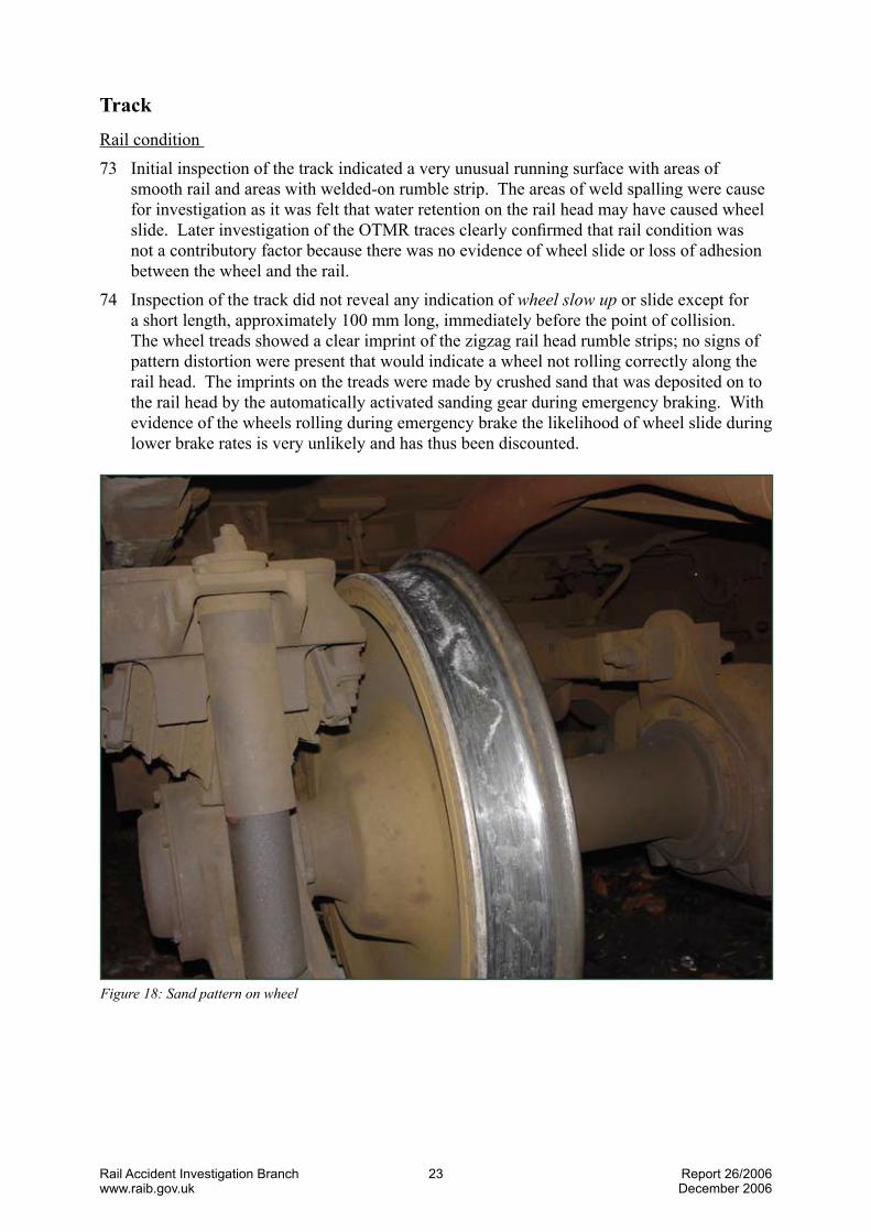
74 Inspection of the track did not reveal any indication of wheelslowup or slide except for a short length, approximately 100 mm long, immediately before the point of collision. The wheel treads showed a clear imprint of the zigzag rail head rumble strips; no signs of pattern distortion were present that would indicate a wheel not rolling correctly along the rail head. The imprints on the treads were made by crushed sand that was deposited on to the rail head by the automatically activated sanding gear during emergency braking. With evidence of the wheels rolling during emergency brake the likelihood of wheel slide during lower brake rates is very unlikely and has thus been discounted.
Figure18:Sandpatternonwheel

Rail Accident Investigation Branchwww.raib.gov.uk
2� Report 26/2006December 2006
75 Areas of sand deposit unaffected by any rolling wheel were also found on the rail head immediately below the sand pipes. This was caused by residual sand continuing to flow down the delivery pipes after the sand demand had been switched off due to the train being stationary.
76 When a train traverses a section of rail with rumble strips a very distinctive and intrusive noise can be heard. The remedial grinding work on the rumble strips would have changed the pattern of this noise. There is no evidence that this was as a contributory factor in the accident.
77 Analysis of the rail head and wheel tread swabs taken within four hours of the accident showed some signs of minor contamination by mineral oil and diesel fuel. This was consistent with that expected for a terminal platform track used regularly by diesel trains. The contamination was not sufficient to cause wheel slide or wheel slow up, as has been shown separately by analysis of the OTMR records.
78 Contamination was also found on the surface of the rail near the TPWS loops at the entry end to the platform area. This is believed to be a fine grinding dust that would moderately enhance the frictional coefficient between the rails and wheels and not reduce it. It did not extend on to the rail head where braking for the final stop would be required. This has been discounted as a contributory factor in the accident.
79 Measurements were taken of the fictional coefficient of the rail surface using portable test instrumentation. Although taken more than 12 hours after the collision and after the train had been moved, they did show that the friction values were well within the acceptable range.
80 The likelihood of wheel slide being a contributory factor in the collision has thus been discounted.
Figure19:‘Bestpractice’trainapproachtobufferstops

Rail Accident Investigation Branchwww.raib.gov.uk
2� Report 26/2006December 2006
Traindriving81 The driver duties at any turn round include switching destination and tail lights, changing
destination blinds, electrically closing down the controls in one cab, walking to the other end of the train, opening up that cab, setting the headlights, taillights and destination blind. At Sudbury the driver must also contact the signaller by telephone to get permission to leave.
82 The booked time in theWorkingTimetable for the turn-round at Sudbury was 6 minutes, however each trip had a longer lay-over at Marks Tey. Due to the lateness of departure from Marks Tey the crew would have had a reduced time for the turn-round at Sudbury; 3 minutes for an on-time departure at 18:30 hrs.
83 The timing of the accident at just after 18:27 hrs indicates that no time had been made up on the trip from Marks Tey. The evidence from the two OTMRs confirms that the driver had not driven the trip in a manner of ‘trying to make up time’. It is possible however that the thought of the short turn round might have marginally affected the driver’s control of the speed on the approach to Sudbury. The appropriate reduction in speed for the two PSRs on the approach to Sudbury and the 10 mph (16 km/h) TPWS loops indicates that this was unlikely.
84 The train driving policy published by ‘one’ (see Appendix C) includes a number of requirements about controlling the train on the approach to buffer stops. It specifically mentions the need to:
l Aim for a maximum speed of 15 mph (24 km/h) at the platform ramp when approaching terminal stations or bay platforms, unless another restriction applies. Control the speed reduction progressively along the platform length.
l Reduce speed to walking pace 1 coach length from the buffer stops. l Always stop the train a minimum of 2 m (6 ft) short when approaching buffer stops. These instructions are similar to those issued by other train operating companies. 85 The ‘one’ Train Driving Policy (See Appendix C) details the technique for applying STEP
1 and STEP 2 brakes when bringing the train to a stand. The OTMR records show that the train speed (7.6 mph or 12 km/h) was higher than the guideline of ‘walking pace’
(4 mph or 6.4 km/h) at one coach length from the buffer stops. The document indicates that it would have been appropriate to move the brake handle to STEP 1 or greater at one coach length from the buffer stops. The OTMR records show that the brake wires only began to change state when the train was less than 10 m from the buffer stops and travelling at 7.6 mph (12 km/h).
86 After the collision the TPWS was checked by Network Rail signal technicians working under the direction of an RAIB inspector. The track mounted loops were functioning correctly as determined from the electrical inputs and radiated signal. The two loops are positioned so that any train speed above 10 mph (16 km/h) will cause an irrevocable emergency brake to be applied. Their distance from the normal stopping point allows a service brake to be applied for all normal approaches. Subsequent checks of the train-mounted TPWS system at Norwich Crown Point depot confirmed that the equipment was operating correctly. The lack of any TPWS brake intervention on the approach to the platform, confirmed by the OTMR, indicates that the driver had reduced the speed appropriately on the approach to the platform. An over-speed or erratic approach to the station has thus been discounted.

Rail Accident Investigation Branchwww.raib.gov.uk
26 Report 26/2006December 2006
Communications87 The communications between Sudbury and the controlling signal box are recorded.
The tapes show that the message from the driver did not comply with the requirements for safety critical communications; in particular no mention was made that it was an emergency call. The form of conversation from the driver was rather informal. It is possible that the shocked state of the driver could explain this approach.
Human factors88 Prior to the accident the driver stopped the train at the far end of the platform at Bures.
This was legitimate, however the reason that the driver did this is not known. This is not considered to be a factor in the accident.
89 There is no evidence that there was any distraction in the drivers mind due to external or personal issues.
90 The results of the drugs & alcohol test on the driver were negative. Following the accident, ‘one’ arranged for the driver to undergo a medical examination that included an eyesight test that met the requirements of Railway Group Standard GO/RT3251. The driver had taken a rest day four days prior to the accident and had not been subject to subsequent work shift changes. Medical factors have been eliminated as a cause of the accident.
Training of staff91 ‘one’ provides a package of training and assessment for its drivers. This includes the
application of defensive driving techniques and on the correct manner in which a train should be controlled on the approach to buffer stops. The driver had completed a rules assessment in August 2004 whilst his driving technique had been assessed by means of a cab ride 24 days prior to the accident. The assessment process operated by ‘one’ was fully up to date. Skills and knowledge do not therefore appear to be a factor in the collision.
92 The driver had in excess of 6 years experience driving trains and was fully conversant with the route, having regularly driven trains of a similar type to Sudbury over past years.
93 In July 2004 the driver was involved in a SPAD at Great Bentley. That investigation highlighted loss of concentration as a contributory factor. In accordance with ‘one’ safety procedures, he was subsequently subject to special monitoring.
94 After the accident the driver apologised to passengers first and then reported the occurrence to the signaller as required by the railway rule book. The conductor firstly attempted to take names and addresses of passengers and possible witnesses as they were offered to him, and then checked the train for any injured passengers. The conductor experienced conflicting calls for attention; ‘one’ should thus reassess the training and guidance given to staff to ensure that they have a clear understanding of what priority various matters should be given. This guidance could usefully be provided in a form that could easily be carried around, or perhaps be permanently provided in driving cabs and conductor’s compartments (Recommendation 1).
OTMR analysis95 Records of the OTMRs fitted to both the leading and trailing cabs were analysed (see
Figures 12 and 13). They displayed very similar records for the critical traces of train speed and brake wire energisation. A minor timing difference was apparent between the two records that has been put down to a feature of the unsynchronised internal clocks and the system software for logging data. It has not been investigated further.
Rail Accident Investigation Branchwww.raib.gov.uk
27 Report 26/2006December 2006
96 Shortly before the impact the OTMRs record that train wire 23 goes through the following sequence:
l energised; l de-energised; l energised; l de-energised; l de-energised. Three changes of state are evident. This is consistent with the control handle being moved
from the RELEASE position.97 As noted in paragraphs 42 and 43 the driver’s recollection of braking is different to that
shown by the OTMRs. Had the sequence started from the STEP 1 position the sequence for the final approach would have been:
l de-energised; l energised; l de-energised; l de-energised. There would thus have been two changes of state. A much earlier change of state would
also exist representing the change from RELEASE to STEP 1 some distance from the time of collision. This earlier change has not been found in either of the two OTMR records.
98 Had a fault existed in the brake controller or on the train wires it is highly unlikely that the correct sequence of energisation changes on the train wires would be achieved. From inspection of the OTMR data, no evidence of such a fault existed before the accident, nor was one found during subsequent testing at Norwich. Thus it is probable that the origin of the braking sequence was from the RELEASE position and not from STEP 1.
99 The speed of the initial impact of the train with the buffer stops was determined by calculation of the deceleration rates from the speed trace. The electrical signal to the OTMR relating to the speed of the train is derived from an electronic sensor measuring the rotation of an axle. Due to inertial and weight transfer effects acting on the springs and dampers between the bogies and the coach body, the deceleration of the coach body will be different to that of the axle. No attempt has been made to calculate the actual deceleration of the coach body.
100 Figure 12 shows the speed distance curve of the leading coach. At the discontinuity identified by ‘point of collision’ the deceleration rate changes dramatically to a figure of 1.88 g (18.4 m/s2), which then lasts for a relatively short period of time. This value cannot be explained other than by the train coming into contact with the buffer stop. Normal train braking is below 0.1 g (0.98 m/s2).
101 The speed trace for both OTMRs shows an initial drop from 6.4 mph (10.2 km/h) to 2 mph (3.2 km/h), it then climbs rapidly to 10 mph (16 km/h) and is followed by an exponential decay curve to zero. This feature has not been investigated but its cause is believed to be due to the tripping of a number of circuit breakers caused by the rapid deceleration. Despite this feature, the integrity of the OTMR data has separately been proven by the analysis of records relating to runs before and after the collision.

Rail Accident Investigation Branchwww.raib.gov.uk
2� Report 26/2006December 2006
Severityofcollision102 The impact occurred at low speed and hence the injuries sustained by the minority of
passengers were relatively minor.103 The provision of TPWS over-speed detection loops has been mandated both by Railway
Group Standards and by legislation. The buffer stop loops at the entrance to the station provide a useful means of ensuring approach speeds are controlled to a ‘safe’ value. The normal set speed of 10 mph (15 km/h) and the distance of the loops from the buffer stops are inter-related. They are a compromise with the speed, gradient and braking profiles. It is not practical to use a trigger speed below 10 mph (15 km/h).
104 The speed trace of the OTMRs shows that the driver correctly braked down to below 10 mph (15 km/h) prior to passing over the TPWS buffer stop loops on the approach to the platform. Whilst it has not been possible to determine what effect TPWS had on the severity of this accident, it is certain that the presence of TPWS caused the driver to suitably control the speed of the train on the approach to the platform, thus limiting the possible collision speed.
105 The buffer stops are of a traditional design, fabricated from second-hand bullhead rail. Many examples of this design can be found all over the Network Rail network, often at the end of sidings. There are two failings of the type that is provided at Sudbury:
a) There is no buffing or seating block that mates with the centre coupler. b) It does not offer any form of controlled retardation. 106 The absence of a centre buffing block resulted in the tongue of the coupler on the train
taking the initial brunt of the impact as it hit and fractured one of the buffer stop cross rails.
107 The energy of the collision was dissipated by the bending and fracture of the buffer stop and by bending of various parts of the train. Even with the low speed and deceleration experienced it is possible that a different design of buffer stop may might have beneficially altered the jerk experienced by the passengers that caused them to be thrown forward. The provision of a more modern design of buffer stop would enable these forces to be focused into defined areas with more predictable results for the train deceleration.
108 Replacement of the buffer stop by a more modern design that includes a retardation mechanism would be an advantage; however these designs invariably require an additional length of track on which to fit them. At Sudbury fitment of such a design would almost certainly require the platform to be lengthened and for the TPWS loops and other electrical systems to be altered. The service pattern and likelihood of a repeat incident may make the expenditure difficult to justify. Nevertheless Network Rail should investigate the provision of an alternative design of buffer stop that should be fitted if it is practical to do so (Recommendation 2).
109 The damage to the train was relatively minor. The coupler, gangway connection and obstacle deflector all required remedial action prior to the train re-entering service. There was no evidence that caused concern regarding the train’s crashworthiness.
110 The injuries caused to passengers were all caused by falls which resulted in impacts with other passengers, luggage, seats, bulkheads, doorways and floor. Most of the bruising, cuts and abrasions received were relatively minor and not long lasting. One passenger has however reported longer lasting injuries including displaced ribs, pelvic rotation and whiplash. There is no evidence that causes concern regarding the internal design of the train in relation to these injuries.

Rail Accident Investigation Branchwww.raib.gov.uk
2� Report 26/2006December 2006
111 The immediate cause of the accident was due to the late application of brakes during the final approach along the platform track. The only likely explanation of this is of misjudgement by the driver.
112 Apart from human error, no identifiable causal factors were found.113 No identifiable factors were considered to be contributory.114 The following factors affected the consequences of the collision: l the presence of TPWS. This did not intervene to apply an emergency brake because the
approach speed was controlled to less than 10 mph (15 km/h); l the design of the buffer stop; l the number of standing passengers waiting to detrain.
Conclusions

Rail Accident Investigation Branchwww.raib.gov.uk
�0 Report 26/2006December 2006
115 Apart from specific investigations and remedial action on the unit involved in the collision, ‘one’ has completed a fleet check of all brake application chokes. One incorrectly sized choke was replaced.
116 ‘one’ has undertaken its own investigation into the accident and has identified a number of operational actions that it is implementing:
l All drivers and conductors who are rostered to work the Sudbury line to be re-briefed on the requirements of cab access and cab discipline.
l A system of routine monitoring to be introduced for the Sudbury line. This system should monitor local risks such as unauthorised access to driving cabs, as opposed to staff competence.
l An examination of the necessity of introducing a similar monitoring scheme to similar branch lines.
117 ‘one’ has also recommended that: l Network Rail consider the removal of the permanent speed restriction board situated on
the approach to Sudbury Station. If the board is to remain in place it Network Rail should consider reducing the permissible speed to 10 mph (16 km/h), in line with the speed setting for the TPWS over-speed loops.
Actions already taken or in progress

Rail Accident Investigation Branchwww.raib.gov.uk
�1 Report 26/2006December 2006
118 The following safety recommendations are made:1
1 Responsibilities in respect to these recommendations are set out in the Railways (Accident Investigation and Reporting) Regulations 200� and the accompanying guidance notes, which can be found on the RAIB web site at www.raib.gov.uk
Recommendations
1. ‘one’ should provide some clear guidance for the train crew on the ideal order of attending to various duties following an accident (it may be useful for this to be provided in a form that can easily be carried around or that could be provided in each driving cab and conductor’s compartment) (paragraph 94).
2. Network Rail should: l carry out a review, including cost benefit analysis, into the practicability of
providing energy absorbing buffer stops at terminal platforms; l provide a copy of the review to the safety authority; l develop a programme to fit energy absorbing buffer stops to terminal platforms
where it is reasonably practicable to do so.
119 Recommendation 1, above, also has applications to other Train Operating Companies, which should assess the need to apply the lessons of this investigation to their own activities.

Rail Accident Investigation Branchwww.raib.gov.uk
�2 Report 26/2006December 2006
Glossaryofabbreviationsandacronyms AppendixAPSR Permanent Speed Restriction
TPWS Train Protection and Warning System
NRN National Radio Network
OTMR On Train Monitoring Recorder
Appendices

Rail Accident Investigation Branchwww.raib.gov.uk
�� Report 26/2006December 2006
Glossaryofterms AppendixBBerth (berthed) A precise location on the railway, eg in a station, in which a train is expected to stand.
Brake application The time that the brake cylinder pressure takes to reach the required time pressure. The pressure – time curve is of exponential form. The time of application is controlled by chokes in the air systems which ensure that jerks are not produced within the train.
Brake distributor A part of the brake system that controls the air pressure in the brake cylinders.
Choke A restriction in an air pipe that provides a controlled rate of pressure rise within a part of the compressed air system.
Late notice case A notice case adjacent to where staff sign on for duty. It contains important information that is too recent to be included in the weekly operating notices issued to each driver.
Master switch A rotary switch on the driver’s desk that selects Forward or Reverse direction or Neutral or Off.
National Radio A band 3 radio system used for communications between the signaller Network (NRN) or controller and the train. It is an ‘open access’ which means that all radios switched on to an area frequency can hear the communication.
On Train Monitoring An ‘on-board’ data logging system that records the state of various Recorder (OTMR) train controls and systems. It also records train speed.
One train working A means of operating a railway line by only permitting one train towith no train staff be present.system
Rumble strip Weld deposits added to the head of the rail in a zigzag pattern to ensure a good electrical contact between the rail and wheel for track circuit purposes. It is used in areas where the rail head is not kept clean from the normal rail traffic.
Spalling Flaking of metal from the surface of the rail leaving it covered in pits. Tare The weight of the coach without passengers or luggageTrack circuit An electrical circuit that detects the absence of a train on a section of
railway line.Train detection The means of proving that a train is absent or present in a section of railway line. It can be by means of a track circuit or other methods.
Train Protection and A system that provides train stop and overspeed protection at some Warning System signals, overspeed protection at some speed restrictions and at (TPWS) passenger platforms with buffer stops. It functions by applying an emergency brake on the train. Except in special circumstances (which do not apply at Sudbury) the maximum permitted approach speed to a buffer stop is 10 mph (15 km/h).

Rail Accident Investigation Branchwww.raib.gov.uk
�� Report 26/2006December 2006
Westcode brake A proprietary ‘energise-to-release’ braking system produced by the Westinghouse Brake and Signal Company. It is in use on many multiple unit diesel and electric trains in the UK. Failure of the electricity supply or a deliberate interruption by interlocks causes an emergency brake to be applied. Normal service brake pressure is applied in a number of discrete steps.
Wheel slide The condition when a wheel stops rotating and slides along the rail surface. This can result in a flat area being worn on the periphery of the wheel which results in an obtrusive banging when the wheel rotates again. The retardation forces available are less than for a wheel rotating correctly.
Wheel slow-up The condition when a wheel rotates slower than the normal rolling speed. It often deteriorates rapidly into wheel slide.
Working timetable The timetable issued by Network Rail that provides the times necessary for the efficient running and control of the railway.
Wrong side failure A failure that causes an item of equipment to cease functioning in such a way as to permit or cause danger.

Rail Accident Investigation Branchwww.raib.gov.uk
�� Report 26/2006December 2006
References AppendixC1 ‘one’ BrakingandWorkingInstructionsforAutomaticBrakes. Drivers Manual Section 2. Issue 1: November 20042 ‘one’ TrainDrivingPolicy Safety Manual Appendix1.10/A Issue 1: November 20053 RegionalRailwaysClass15xPostIncidentBrakeTest TU/TP0385 Issue 1: June 1993

This report is published by the Rail Accident Investigation Branch, Department for Transport.
© Crown copyright 2006
Any enquiries about this publication should be sent to:
RAIB Telephone: 01��2 2���00The Wharf Fax: 01��2 2���01Stores Road Email: [email protected] UK Website: www.raib.gov.ukDE21 �BA


