Gully Erosion Part 1 - Gully erosion and its causes
10
© Catchments & Creeks Pty Ltd April 2010 Page 1 Gully Erosion – Part 1 GULLY EROSION AND ITS CAUSES Gully erosion – “A complex of processes whereby the removal of soil is characterised by incised channels in the landscape.” NSW Soil Conservation Service, 1986. Photo 1 – Head of gully erosion (Qld) Photo 2 – Rural gully erosion (SA) Introduction Gully erosion is usually distinguished from the boarder term ‘watercourse erosion’ by the path the erosion follows, which is normally along an overland flow path rather than along a creek. Prior to the occurrence of the gully erosion, the overland flow path would likely have carried only shallow concentrated flows conveying stormwater runoff to a down-slope watercourse. Gully erosion, however, can also occur within a watercourse, typically within the upper reaches, and typically resulting from an active ‘head-cut’ migrating rapidly up the valley. Gully erosion is best characterised as a ‘bed instability’ that subsequently causes in ‘bank instabilities’. Unstable banks maybe the most visible aspect of gully erosion; but stabilisation of a gully normally needs to start with stabilisation of the gully bed. The mechanics of gully erosion Most gullies start out as shallow overland flow paths that carry flows only during periods of heavy rainfall (Figure 1). An extraordinary event of some type causes an initial erosion point or ‘nick’ point (Photo 3) to form somewhere along the drainage path. A bell-shaped scour hole sometimes forms at the head of the gully (Photo 4), which is usually deeper than the immediate downstream gully bed. Photo 3 – ‘Nick’ point representing the early stages of gully erosion (SA) Photo 4 – Early stage of gully erosion within an urban overland flow path (Qld)
Transcript of Gully Erosion Part 1 - Gully erosion and its causes
© Catchments & Creeks Pty Ltd April 2010 Page 1
Gully Erosion – Part 1 GULLY EROSION AND ITS CAUSES
Gully erosion – “A complex of processes whereby the removal of soil is characterised by incised channels in the landscape.” NSW Soil Conservation Service, 1986.
Photo 1 – Head of gully erosion (Qld) Photo 2 – Rural gully erosion (SA) Introduction Gully erosion is usually distinguished from the boarder term ‘watercourse erosion’ by the path the erosion follows, which is normally along an overland flow path rather than along a creek. Prior to the occurrence of the gully erosion, the overland flow path would likely have carried only shallow concentrated flows conveying stormwater runoff to a down-slope watercourse.
Gully erosion, however, can also occur within a watercourse, typically within the upper reaches, and typically resulting from an active ‘head-cut’ migrating rapidly up the valley.
Gully erosion is best characterised as a ‘bed instability’ that subsequently causes in ‘bank instabilities’. Unstable banks maybe the most visible aspect of gully erosion; but stabilisation of a gully normally needs to start with stabilisation of the gully bed. The mechanics of gully erosion Most gullies start out as shallow overland flow paths that carry flows only during periods of heavy rainfall (Figure 1). An extraordinary event of some type causes an initial erosion point or ‘nick’ point (Photo 3) to form somewhere along the drainage path. A bell-shaped scour hole sometimes forms at the head of the gully (Photo 4), which is usually deeper than the immediate downstream gully bed.
Photo 3 – ‘Nick’ point representing the early stages of gully erosion (SA)
Photo 4 – Early stage of gully erosion within an urban overland flow path (Qld)
© Catchments & Creeks Pty Ltd April 2010 Page 2
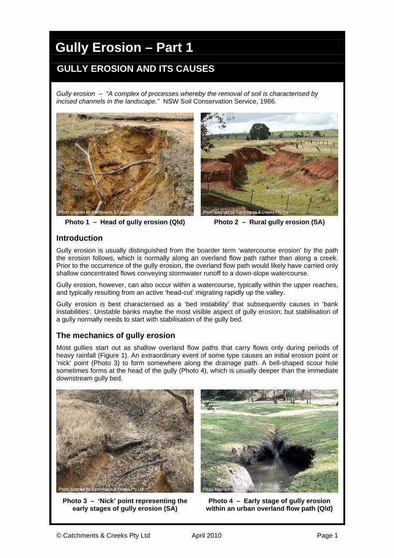
The initial nick point usually occurs at the downstream end of the gully, and usually at a significant change in grade along the flow path, such as the point where the overland flow spills into a watercourse.
Figure 1 – Land profile before the commencement of gully erosion
Head-cut erosion then causes the head of the gully to migrate up the valley forming the gully (Figure 2). Ongoing rainfall and stormwater runoff expands the gully in both length and width.
Figure 2 – Initial stages of gully erosion showing the migration of the gully head up the
valley after the initial formation of a ‘nick’ point somewhere along the drainage line Gully erosion can also start as a ‘rill’ (a shallow cut in the landscape) usually steep-sided and V-shaped, which expand by ongoing erosion to form a gully.
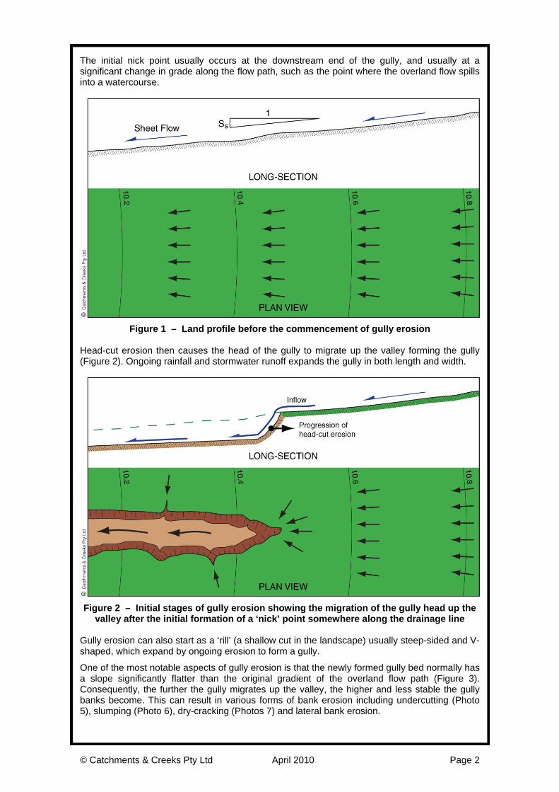
One of the most notable aspects of gully erosion is that the newly formed gully bed normally has a slope significantly flatter than the original gradient of the overland flow path (Figure 3). Consequently, the further the gully migrates up the valley, the higher and less stable the gully banks become. This can result in various forms of bank erosion including undercutting (Photo 5), slumping (Photo 6), dry-cracking (Photos 7) and lateral bank erosion.
© Catchments & Creeks Pty Ltd April 2010 Page 3
Figure 3 – The gully banks usually experience ongoing erosion caused by surface
runoff spilling laterally into the gully (a process known as lateral bank erosion) Dry-cracking results from the extreme drying of the soils, which results in extensive cracking that can allow the soil to crumble and fall to the bed of the gully. Deep cracks beyond the top of bank can also result from bank undercutting or slumping. Deep, continuous cracks midway down a bank (Photo 8) can indicate high shrink-swell soils, or a slump-type bank failure along the edge of a concentrated mass of tree roots.
Photo 5 – Undercutting bank erosion (Qld) Photo 6 – Bank slumping (SA)
Photo 7 – Dry weather bank failures are evident by the fact that the displaced soil is
undisturbed by stream flows (Qld)
Photo 8 – Deep cracks can result from drying or movement between root-bound and non root-bound soils horizons (SA)
© Catchments & Creeks Pty Ltd April 2010 Page 4
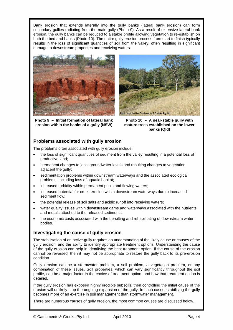
Bank erosion that extends laterally into the gully banks (lateral bank erosion) can form secondary gullies radiating from the main gully (Photo 9). As a result of extensive lateral bank erosion, the gully banks can be reduced to a stable profile allowing vegetation to re-establish on both the bed and banks (Photo 10). The entire gully erosion process from start to finish typically results in the loss of significant quantities of soil from the valley, often resulting in significant damage to downstream properties and receiving waters.
Photo 9 – Initial formation of lateral bank erosion within the banks of a gully (NSW)
Photo 10 – A near-stable gully with mature trees established on the lower
banks (Qld)
Problems associated with gully erosion The problems often associated with gully erosion include: • the loss of significant quantities of sediment from the valley resulting in a potential loss of
productive land; • permanent changes to local groundwater levels and resulting changes to vegetation
adjacent the gully; • sedimentation problems within downstream waterways and the associated ecological
problems, including loss of aquatic habitat; • increased turbidity within permanent pools and flowing waters; • increased potential for creek erosion within downstream waterways due to increased
sediment flow; • the potential release of soil salts and acidic runoff into receiving waters; • water quality issues within downstream dams and waterways associated with the nutrients
and metals attached to the released sediments; • the economic costs associated with the de-silting and rehabilitating of downstream water
bodies. Investigating the cause of gully erosion The stabilisation of an active gully requires an understanding of the likely cause or causes of the gully erosion, and the ability to identify appropriate treatment options. Understanding the cause of the gully erosion can help in identifying the best treatment option. If the cause of the erosion cannot be reversed, then it may not be appropriate to restore the gully back to its pre-erosion condition.
Gully erosion can be a stormwater problem, a soil problem, a vegetation problem, or any combination of these issues. Soil properties, which can vary significantly throughout the soil profile, can be a major factor in the choice of treatment option, and how that treatment option is detailed.
If the gully erosion has exposed highly erodible subsoils, then controlling the initial cause of the erosion will unlikely stop the ongoing expansion of the gully. In such cases, stabilising the gully becomes more of an exercise in soil management than stormwater management.
There are numerous causes of gully erosion, the most common causes are discussed below.
© Catchments & Creeks Pty Ltd April 2010 Page 5
(a) Land clearing
Tree clearing, even if replaced by other vegetation such as grass or crops, can significantly alter the runoff characteristics of a catchment, and as a result, cause long-term changes to downstream waterways. Specifically, de-forestation has the potential to: • reduce rainfall infiltration; • reduce the volume of stormwater temporarily retained on plant leafs and surface mulch; • increase the frequency and duration of both low and high-flows within streams; • increase the total annual volume of stormwater runoff; • alter the health and biodiversity of instream ecology.
It has long been observed that changes in vegetation cover, including de-forestation as a result of land clearing and bushfires, can result in significant changes to the annual flow of stormwater from catchments (refer to various studies reported by Melbourne Water).
Even though erosion is a natural aspect of all waterways, the basic aim should be to avoid an unnatural acceleration or deceleration of this erosion. Stream flows at or near the bankfull flow rate are normally considered to have the greatest influence on channel erosion; however, gully erosion can be advanced by both the frequent low-flows and the infrequent flood flows.
The impacts of land clearing are more likely to affect minor waterways such as gullies and creeks. There are generally four types of creek systems: clay-based, sand-based, gravel-based and spilling (rocky) creeks. Each of these waterways will respond differently to land clearing.
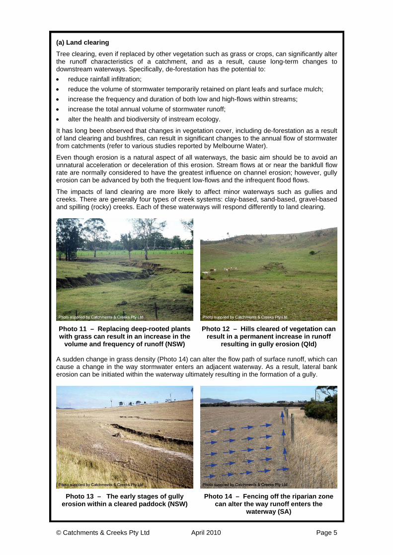
Photo 11 – Replacing deep-rooted plants with grass can result in an increase in the
volume and frequency of runoff (NSW)
Photo 12 – Hills cleared of vegetation can result in a permanent increase in runoff
resulting in gully erosion (Qld) A sudden change in grass density (Photo 14) can alter the flow path of surface runoff, which can cause a change in the way stormwater enters an adjacent waterway. As a result, lateral bank erosion can be initiated within the waterway ultimately resulting in the formation of a gully.
Photo 13 – The early stages of gully erosion within a cleared paddock (NSW)
Photo 14 – Fencing off the riparian zone can alter the way runoff enters the
waterway (SA)
© Catchments & Creeks Pty Ltd April 2010 Page 6
(b) Urbanisation
Urbanisation can have a similar influence to that of deforestation. The effect, however, is more commonly observed as ‘accelerated creek erosion’ rather than gully erosion.
Significant changes can occur to the size of waterways following the growth of poorly managed urbanisation. The extent of these changes primarily depends on the type and degree of changes to the catchment hydrology.
In order to minimise the risk of accelerated creek erosion, consideration must be given to those measures that will minimise changes to: • the annual volume of stormwater runoff; • the frequency and duration of near-bankfull flows; and • the peak discharge of those stream flows greater than or equal to the bankfull flow rate.
The focus of stormwater management programs, however, should not be to just reduce changes to the annual runoff volume, but to reduce changes in the runoff volume of those storms that are likely to contribute to near-bankfull flows. Thus the focus will likely be on storms with an average recurrence interval (ARI) of between 1 in 1 year and 1 in 10 years.
It should also be noted that an increase in the frequency and duration of low-flows within a waterway (i.e flows less than the 1 in 1 year ARI) may increase the stress on instream aquatic ecology and habitats.
Consequently the only way to minimise the risk of both accelerated creek erosion, and a decline in urban aquatic habitats, is to minimise changes to the natural water cycle, including the frequency, duration, velocity, volume and peak discharge of rainfall events of all stream flows.
In urban areas this can usually be achieved, in part, by: • adopting the principles of Water Sensitive Urban Design; • minimising changes in impervious surface area, particularly on highly porous soils; • decreasing the percentage of directly connected impervious surfaces; • maximising stormwater infiltration; • using rainwater harvesting to minimise changes to runoff volume; • adopting stormwater ‘retention’ rather than ‘detention’ systems.
It is not possible to accurately predict the response of natural, earth-lined waterways to changes in catchment hydrology. Past history has shown that in the absence of major flow control systems (i.e. dams and retention basins), urban creeks typically expand from around a 1 to 2 year ARI bankfull capacity, to around a 5 to 10 year ARI bankfull capacity following urbanisation.
Rather than reduce the risk of accelerated creek erosion, stormwater ‘detention’ practices can actually increase this erosion by increasing the duration of near-bankfull flows. As a result, modern stormwater management practices now focus on stormwater retention and stormwater
arvesting. h
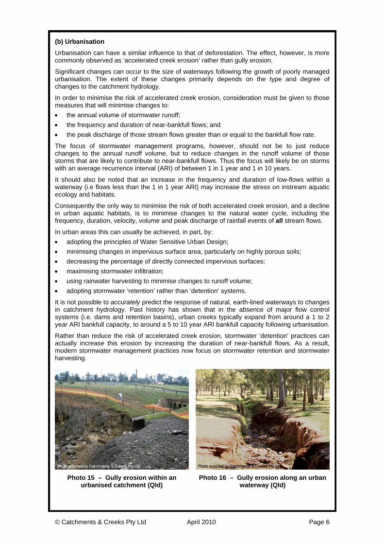
Photo 15 – Gully erosion within an urbanised catchment (Qld)
Photo 16 – Gully erosion along an urban waterway (Qld)
© Catchments & Creeks Pty Ltd April 2010 Page 7
(c) Exposure of weak subsoil
Gully erosion is often triggered by the exposure of a weak subsoil layer beneath a streambed. Exposure of the weak subsoil layer can result from natural erosion processes, or human activities. Examples of such human activities include: • accelerated channel erosion resulting from deforestation or urbanisation; • exposure of the weak subsoil during the construction of a watercourse crossing; • exposure of the subsoil during channel realignment or extensive weed control activities.
If the exposed subsoil is dispersive (e.g. a sodic soil), then the resulting gully erosion is normally both deep and highly mobile.
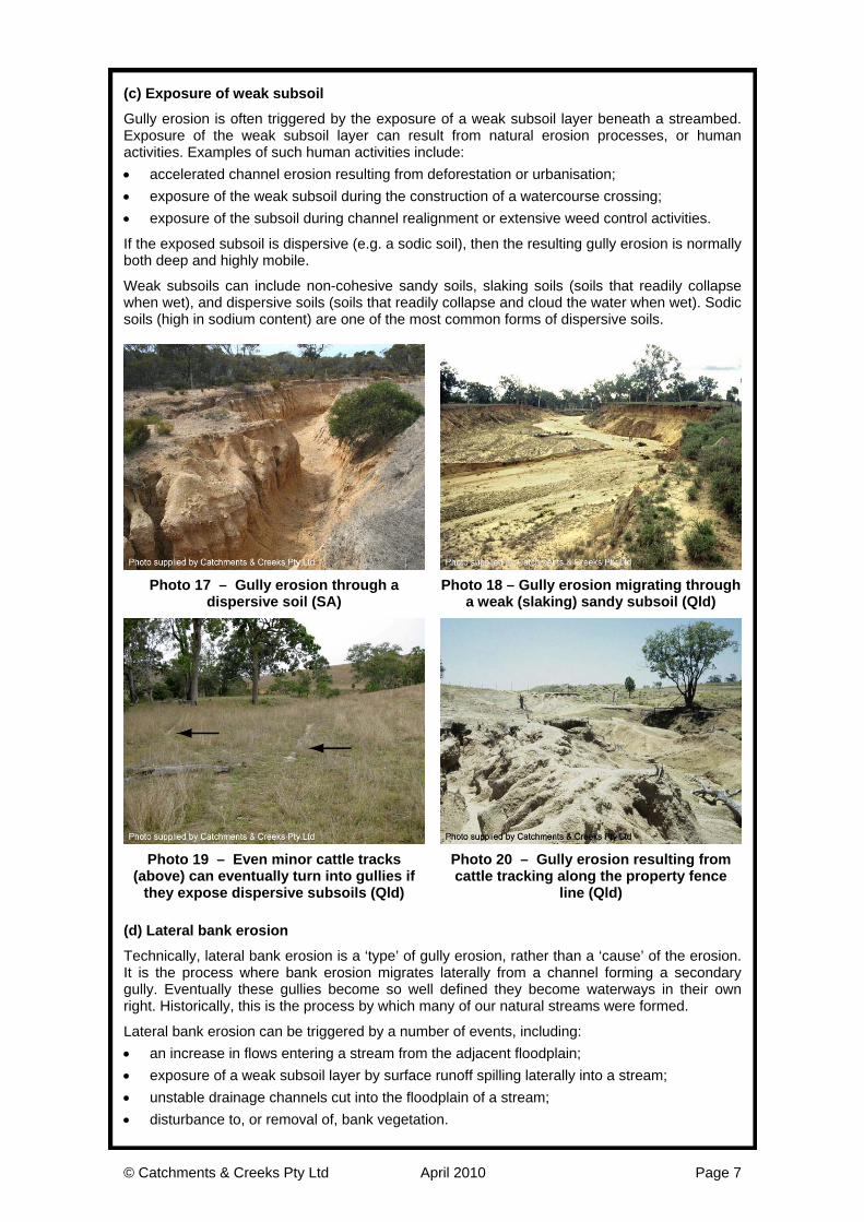
Weak subsoils can include non-cohesive sandy soils, slaking soils (soils that readily collapse when wet), and dispersive soils (soils that readily collapse and cloud the water when wet). Sodic soils (high in sodium content) are one of the most common forms of dispersive soils.
Photo 17 – Gully erosion through a dispersive soil (SA)
Photo 18 – Gully erosion migrating through a weak (slaking) sandy subsoil (Qld)
Photo 19 – Even minor cattle tracks (above) can eventually turn into gullies if
they expose dispersive subsoils (Qld)
Photo 20 – Gully erosion resulting from cattle tracking along the property fence
line (Qld) (d) Lateral bank erosion
Technically, lateral bank erosion is a ‘type’ of gully erosion, rather than a ‘cause’ of the erosion. It is the process where bank erosion migrates laterally from a channel forming a secondary gully. Eventually these gullies become so well defined they become waterways in their own right. Historically, this is the process by which many of our natural streams were formed.
Lateral bank erosion can be triggered by a number of events, including: • an increase in flows entering a stream from the adjacent floodplain; • exposure of a weak subsoil layer by surface runoff spilling laterally into a stream; • unstable drainage channels cut into the floodplain of a stream; disturbance to, or removal of, bank vegetation. •
© Catchments & Creeks Pty Ltd April 2010 Page 8
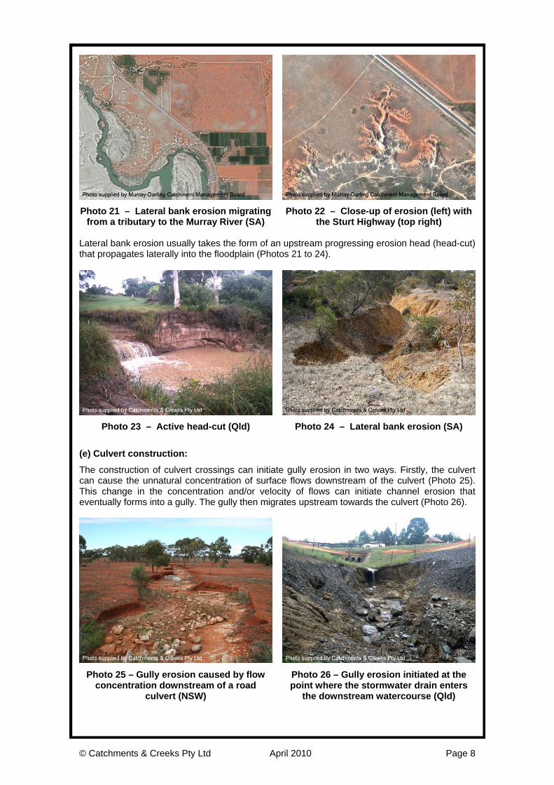
P from a tributary to the Murray River (SA)
Photo with the Sturt Highway (top right)
gressing erosion head (head-cut) at propagates laterally into the floodplain (Photos 21 to 24).
hoto 21 – Lateral bank erosion migrating 22 – Close-up of erosion (left)
Lateral bank erosion usually takes the form of an upstream proth
Photo 23 – Active head-cut (Qld) Photo 24 – Lateral bank erosion (SA)
t ventually forms into a gully. The gully then migrates upstream towards the culvert (Photo 26).
(e) Culvert construction:
The construction of culvert crossings can initiate gully erosion in two ways. Firstly, the culvert can cause the unnatural concentration of surface flows downstream of the culvert (Photo 25). This change in the concentration and/or velocity of flows can initiate channel erosion thae
P concentrat of a road
culvert (NSW) po s
the downstream watercourse (Qld)
hoto 25 – Gully erosion caused by flowion downstream
Photo 26 – Gully erosion initiated at the int where the stormwater drain enter
© Catchments & Creeks Pty Ltd April 2010 Page 9
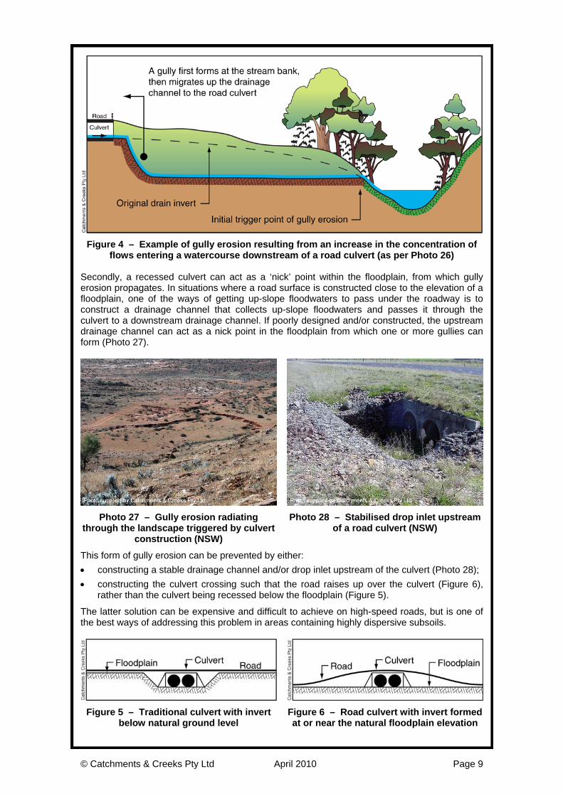
Figure 4 – Example of gully erosion resulting from an increase in the concentration of
flows entering a watercourse downstream of a road culvert (as per Photo 26) Secondly, a recessed culvert can act as a ‘nick’ point within the floodplain, from which gully erosion propagates. In situations where a road surface is constructed close to the elevation of a floodplain, one of the ways of getting up-slope floodwaters to pass under the roadway is to construct a drainage channel that collects up-slope floodwaters and passes it through the culvert to a downstream drainage channel. If poorly designed and/or constructed, the upstream drainage channel can act as a nick point in the floodplain from which one or more gullies can form (Photo 27).
Photo 27 – Gully erosion radiating through the landscape triggered by culvert
construction (NSW)
Photo 28 – Stabilised drop inlet upstream of a road culvert (NSW)
This form of gully erosion can be prevented by either: • constructing a stable drainage channel and/or drop inlet upstream of the culvert (Photo 28); • constructing the culvert crossing such that the road raises up over the culvert (Figure 6),
rather than the culvert being recessed below the floodplain (Figure 5).
The latter solution can be expensive and difficult to achieve on high-speed roads, but is one of the best ways of addressing this problem in areas containing highly dispersive subsoils.
Figure 5 – Traditional culvert with invert below natural ground level
Figure 6 – Road culvert with invert formed at or near the natural floodplain elevation
© Catchments & Creeks Pty Ltd April 2010 Page 10
The design option shown in Figure 6 is normally only required when a road crosses a shallow overland flow path that does not have well-defined bed and banks (examples can be seen in the black soil areas of the Darling Downs, Qld).
If the road crosses a natural watercourse, then upstream gully erosion can be avoided by either: • matching the culvert invert elevation with the bed elevation of the watercourse; or • constructing a stable drop inlet immediately upstream of the culvert.
If maintaining fish passage conditions is a requirement of the watercourse, then the stabilised culvert drop inlet will likely consist of a series of rock riffles with the fall per riffle not exceeding 0.5m, and the gradient not exceeding 1 in 15 to 1 in 30 (depending on local conditions).
It should be noted that the existence of gully erosion immediately downstream of a culvert does not necessarily indicate that the culvert was the cause of the erosion. In many cases it is the culvert that is preventing the upstream progression of the gully erosion, rather than the culvert causing the erosion.
In some cases, the cause of gully erosion is best determined by viewing historical aerial photographs that hopefully show the valley before and after construction of the culvert. Alternatively, investigators can follow the path of the erosion down the gully to check if there is an obvious nick point that initiated the erosion. (f) Construction of unstable drainage channels:
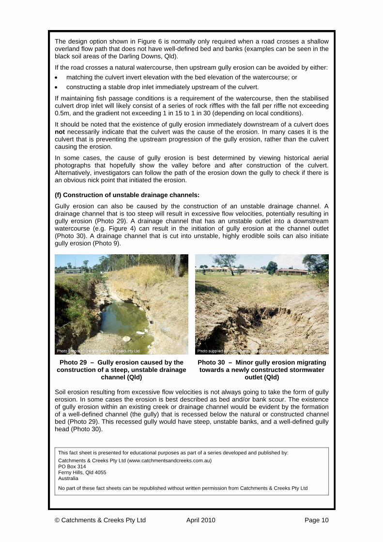
Gully erosion can also be caused by the construction of an unstable drainage channel. A drainage channel that is too steep will result in excessive flow velocities, potentially resulting in gully erosion (Photo 29). A drainage channel that has an unstable outlet into a downstream watercourse (e.g. Figure 4) can result in the initiation of gully erosion at the channel outlet (Photo 30). A drainage channel that is cut into unstable, highly erodible soils can also initiate gully erosion (Photo 9).
Photo 29 – Gully erosion caused by the construction of a steep, unstable drainage
channel (Qld)
Photo 30 – Minor gully erosion migrating towards a newly constructed stormwater
outlet (Qld) Soil erosion resulting from excessive flow velocities is not always going to take the form of gully erosion. In some cases the erosion is best described as bed and/or bank scour. The existence of gully erosion within an existing creek or drainage channel would be evident by the formation of a well-defined channel (the gully) that is recessed below the natural or constructed channel bed (Photo 29). This recessed gully would have steep, unstable banks, and a well-defined gully head (Photo 30).
This fact sheet is presented for educational purposes as part of a series developed and published by: Catchments & Creeks Pty Ltd (www.catchmentsandcreeks.com.au) PO Box 314 Ferny Hills, Qld 4055 Australia
No part of these fact sheets can be republished without written permission from Catchments & Creeks Pty Ltd