GROUP 22A MANUAL TRANSAXLE - Tearstone
24
22A-1 GROUP 22A MANUAL TRANSAXLE CONTENTS GENERAL DESCRIPTION. . . . . . . . . 22A-2 MANUAL TRANSAXLE DIAGNOSIS 22A-5 INTRODUCTION. . . . . . . . . . . . . . . . . . . . . 22A-5 TROUBLESHOOTING STRATEGY . . . . . . 22A-5 SYMPTOM CHART. . . . . . . . . . . . . . . . . . . 22A-5 SYMPTOM PROCEDURES . . . . . . . . . . . . 22A-5 SPECIAL TOOLS . . . . . . . . . . . . . . . . 22A-9 ON-VEHICLE SERVICE . . . . . . . . . . . 22A-10 TRANSMISSION OIL LEVEL CHECK . . . . 22A-10 TRANSMISSION OIL REPLACEMENT . . . 22A-10 TRANSAXLE CONTROL . . . . . . . . . . 22A-11 REMOVAL AND INSTALLATION . . . . . . . . 22A-11 TRANSAXLE ASSEMBLY . . . . . . . . . 22A-17 REMOVAL AND INSTALLATION <5M/T> . 22A-17 REMOVAL AND INSTALLATION <6M/T> . 22A-20 SPECIFICATIONS . . . . . . . . . . . . . . . 22A-24 FASTENER TIGHTENING SPECIFICATIONS. . . . . . . . . . . . . . . . . . . . 22A-24 LUBRICANT . . . . . . . . . . . . . . . . . . . . . . . . 22A-24
Transcript of GROUP 22A MANUAL TRANSAXLE - Tearstone
22A-1
GROUP 22A
MANUAL TRANSAXLE
CONTENTS
GENERAL DESCRIPTION. . . . . . . . . 22A-2
MANUAL TRANSAXLE DIAGNOSIS 22A-5INTRODUCTION. . . . . . . . . . . . . . . . . . . . . 22A-5TROUBLESHOOTING STRATEGY . . . . . . 22A-5SYMPTOM CHART. . . . . . . . . . . . . . . . . . . 22A-5SYMPTOM PROCEDURES . . . . . . . . . . . . 22A-5
SPECIAL TOOLS. . . . . . . . . . . . . . . . 22A-9
ON-VEHICLE SERVICE. . . . . . . . . . . 22A-10TRANSMISSION OIL LEVEL CHECK . . . . 22A-10TRANSMISSION OIL REPLACEMENT . . . 22A-10
TRANSAXLE CONTROL . . . . . . . . . . 22A-11REMOVAL AND INSTALLATION . . . . . . . . 22A-11
TRANSAXLE ASSEMBLY . . . . . . . . . 22A-17REMOVAL AND INSTALLATION <5M/T> . 22A-17REMOVAL AND INSTALLATION <6M/T> . 22A-20
SPECIFICATIONS . . . . . . . . . . . . . . . 22A-24FASTENER TIGHTENING SPECIFICATIONS. . . . . . . . . . . . . . . . . . . . 22A-24LUBRICANT . . . . . . . . . . . . . . . . . . . . . . . . 22A-24
GENERAL DESCRIPTIONMANUAL TRANSAXLE22A-2
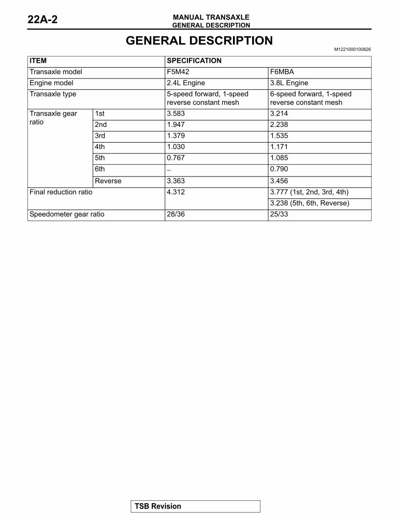
GENERAL DESCRIPTIONM1221000100826
ITEM SPECIFICATIONTransaxle model F5M42 F6MBAEngine model 2.4L Engine 3.8L EngineTransaxle type 5-speed forward, 1-speed
reverse constant mesh6-speed forward, 1-speed reverse constant mesh
Transaxle gear ratio
1st 3.583 3.2142nd 1.947 2.2383rd 1.379 1.5354th 1.030 1.1715th 0.767 1.0856th − 0.790
Reverse 3.363 3.456Final reduction ratio 4.312 3.777 (1st, 2nd, 3rd, 4th)
3.238 (5th, 6th, Reverse)Speedometer gear ratio 28/36 25/33
TSB Revision
GENERAL DESCRIPTIONMANUAL TRANSAXLE 22A-3
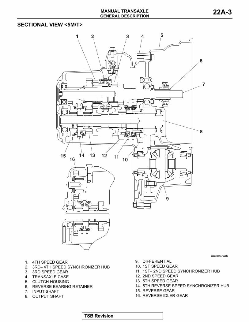
SECTIONAL VIEW <5M/T>
AC309077
1 2 3 4 5
6
7
8
9
10111213141516
AC
1. 4TH SPEED GEAR 2. 3RD− 4TH SPEED SYNCHRONIZER HUB 3. 3RD SPEED GEAR 4. TRANSAXLE CASE 5. CLUTCH HOUSING 6. REVERSE BEARING RETAINER 7. INPUT SHAFT 8. OUTPUT SHAFT
9. DIFFERENTIAL 10. 1ST SPEED GEAR 11. 1ST− 2ND SPEED SYNCHRONIZER HUB 12. 2ND SPEED GEAR 13. 5TH SPEED GEAR 14. 5TH−REVERSE SPEED SYNCHRONIZER HUB 15. REVERSE GEAR 16. REVERSE IDLER GEAR
TSB Revision
GENERAL DESCRIPTIONMANUAL TRANSAXLE22A-4
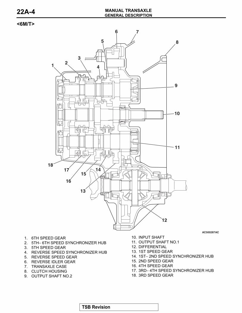
<6M/T>
AC500287
1 23
4
5
6 7
8
9
10
11
12
13
1415
16
1718
AC
1. 6TH SPEED GEAR 2. 5TH− 6TH SPEED SYNCHRONIZER HUB 3. 5TH SPEED GEAR 4. REVERSE SPEED SYNCHRONIZER HUB 5. REVERSE SPEED GEAR 6. REVERSE IDLER GEAR 7. TRANSAXLE CASE 8. CLUTCH HOUSING 9. OUTPUT SHAFT NO.2
10. INPUT SHAFT 11. OUTPUT SHAFT NO.1 12. DIFFERENTIAL 13. 1ST SPEED GEAR 14. 1ST− 2ND SPEED SYNCHRONIZER HUB 15. 2ND SPEED GEAR 16. 4TH SPEED GEAR 17. 3RD− 4TH SPEED SYNCHRONIZER HUB 18. 3RD SPEED GEAR
TSB Revision
MANUAL TRANSAXLE DIAGNOSISMANUAL TRANSAXLE 22A-5
MANUAL TRANSAXLE DIAGNOSISINTRODUCTION
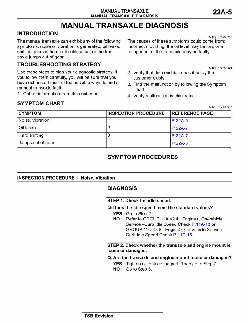
M1221006900756The manual transaxle can exhibit any of the following symptoms: noise or vibration is generated, oil leaks, shifting gears is hard or troublesome, or the tran-saxle jumps out of gear.
The causes of these symptoms could come from: incorrect mounting, the oil level may be low, or a component of the transaxle may be faulty.
TROUBLESHOOTING STRATEGYM1221007000671
Use these steps to plan your diagnostic strategy. If you follow them carefully, you will be sure that you have exhausted most of the possible ways to find a manual transaxle fault.1. Gather information from the customer.
2. Verify that the condition described by the customer exists.
3. Find the malfunction by following the Symptom Chart.
4. Verify malfunction is eliminated.
SYMPTOM CHARTM1221007100667
SYMPTOM INSPECTION PROCEDURE REFERENCE PAGENoise, vibration 1 P.22A-5 Oil leaks 2 P.22A-7 Hard shifting 3 P.22A-7 Jumps out of gear 4 P.22A-8
SYMPTOM PROCEDURES
INSPECTION PROCEDURE 1: Noise, Vibration
DIAGNOSIS
STEP 1. Check the idle speed.Q: Does the idle speed meet the standard values?
YES : Go to Step 2.NO : Refer to GROUP 11A <2.4L Engine>, On-vehicle
Service − Curb Idle Speed Check P.11A-13 or GROUP 11C <3.8L Engine>, On-vehicle Service − Curb Idle Speed Check P.11C-15.
STEP 2. Check whether the transaxle and engine mount is loose or damaged.Q: Are the transaxle and engine mount loose or damaged?
YES : Tighten or replace the part. Then go to Step 7.NO : Go to Step 3.
TSB Revision
MANUAL TRANSAXLE DIAGNOSISMANUAL TRANSAXLE22A-6
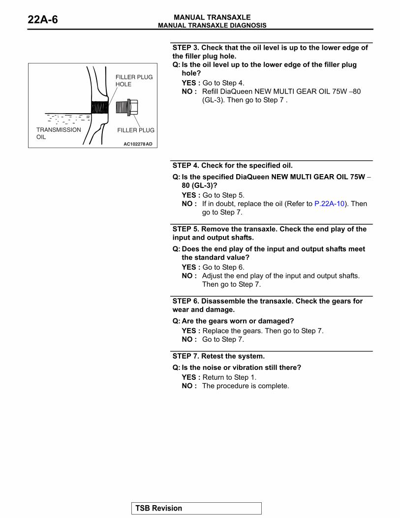
STEP 3. Check that the oil level is up to the lower edge of the filler plug hole.
AC102278AD
FILLER PLUGTRANSMISSIONOIL
FILLER PLUGHOLE
Q: Is the oil level up to the lower edge of the filler plug hole?YES : Go to Step 4.NO : Refill DiaQueen NEW MULTI GEAR OIL 75W − 80
(GL-3). Then go to Step 7 .
STEP 4. Check for the specified oil.Q: Is the specified DiaQueen NEW MULTI GEAR OIL 75W −
80 (GL-3)?YES : Go to Step 5.NO : If in doubt, replace the oil (Refer to P.22A-10). Then
go to Step 7.
STEP 5. Remove the transaxle. Check the end play of the input and output shafts.Q: Does the end play of the input and output shafts meet
the standard value?YES : Go to Step 6.NO : Adjust the end play of the input and output shafts.
Then go to Step 7.
STEP 6. Disassemble the transaxle. Check the gears for wear and damage.Q: Are the gears worn or damaged?
YES : Replace the gears. Then go to Step 7.NO : Go to Step 7.
STEP 7. Retest the system.Q: Is the noise or vibration still there?
YES : Return to Step 1.NO : The procedure is complete.
TSB Revision
MANUAL TRANSAXLE DIAGNOSISMANUAL TRANSAXLE 22A-7
INSPECTION PROCEDURE 2: Oil Leaks
DIAGNOSIS
STEP 1. Visual check.Raise the vehicle, and check for oil leaks. If the oil leak is difficult to locate, steam clean the transaxle and drive the vehicle for at 10 minutes. Then check the leak again.
Q: Is the oil leak(s) found?YES : Go to Step 2.NO : Check for the oil leak(s) around the engine.
Then go to Step 4.
STEP 2. Visual check at the clutch housing.Q: Do oil leaks appear around the joint between the
engine and the clutch housing?YES : Remove the transaxle. Check the input
shaft oil seal, and replace if necessary. Then go to Step 4.
NO : Go to Step 3.
STEP 3. Check the oil seal or O-ring for damage.Q: Is the oil seal or O-ring damaged?
YES : Replace the oil seal or the O-ring. Then go to Step 4.
NO : Go to Step 4.
STEP 4. Check trouble symptoms.Q: Is the oil still leaking?
YES : Return to Step 1.NO : This diagnosis is complete.
INSPECTION PROCEDURE 3: Hard Shifting
DIAGNOSIS
STEP 1. Check the transaxle controlQ: Are the shift cable and the select cable in good
condition?YES : Go to Step 2.NO : Repair or replace the shift cable and the
select cable (Refer to P.22A-11). Then go to Step 7.
STEP 2. Check the transaxle oil.Q: Is the oil dirty?
YES : Replace the oil (Refer to P.22A-10). Then go to Step 7 .
NO : Go to Step 3.
STEP 3. Check the clutch system.Q: Is the clutch system normal?
YES : Go to Step 4.NO : Repair or replace the clutch system (Refer
to GROUP 21A P.21A-3). Then go to Step 7.
STEP 4. Remove and disassemble the transaxle. Check the control housing <5M/T> or selecting bell-crank assembly and control bell-crank dust cover and the shift and select lever shaft <6M/T>.Q: Is the control housing in good condition?
YES : Go to Step 5.NO : Repair or replace the control housing (Refer
to GROUP 22B, Transaxle P.22B-6) <5M/T> or the selecting bell-crank assembly and control bell-crank dust cover and the shift and select lever shaft (Refer to GROUP 22C, Transaxle P.22C-6) <6M/T>. Then go to Step 7.
STEP 5. Check for poor meshing of worn synchronizer ring and gear cone.Q: Is poor meshing or worn synchronizer ring and
gear cone found?YES : Repair or replace the synchronizer ring and
gear cone. Then go to Step 7.NO : Go to Step 6.
TSB Revision
MANUAL TRANSAXLE DIAGNOSISMANUAL TRANSAXLE22A-8
STEP 6. Check the synchronizer spring for weakness.Q: Is the synchronizer spring weak?
YES : Replace the synchronizer spring. Then go to Step 7.
NO : Go to Step 7.
STEP 7. Retest the system.Q: Is the shifting of the gears still hard?
YES : Return to Step 1.NO : The procedure is complete.
INSPECTION PROCEDURE 4: Jumps Out of Gear
DIAGNOSIS
STEP 1. Check the transaxle controlQ: Are the shift cable and the select cable in good
condition?YES : Go to Step 2.NO : Repair or replace the shift cable and the
select cable (Refer to P.22A-11). Then go to Step 6.
STEP 2. Remove and disassemble the transaxle. Check the poppet spring <5M/T> or lock ball assembly <6M/T> for breakage.Q: Is the poppet spring or lock ball assembly broken?
YES : Replace the poppet spring (Refer to GROUP 22B, Transaxle P.22B-6) <5M/T> or the lock ball assembly (Refer to GROUP 22C, Transaxle P.22C-6) <6M/T>. Then go to Step 6.
NO : Go to Step 3.
STEP 3. Check the control housing <5M/T> or selecting bell-crank assembly and control bell-crank dust cover and the shift and select lever shaft <6M/T>.Q: Is the control housing in good condition?
YES : Go to Step 4.NO : Repair or replace the control housing (Refer
to GROUP 22B, Transaxle P.22B-6) <5M/T> or the selecting bell-crank assembly and control bell-crank dust cover and the shift and select lever shaft (Refer to GROUP 22C, Transaxle P.22C-6) <6M/T>. Then go to Step 6.
STEP 4. Check the gear shift forks for wear.Q: Is the gear shift forks worn?
YES : Replace the gear shift fork (Refer to GROUP 22B, Transaxle P.22B-6 <5M/T> or GROUP 22C, Transaxle P.22C-6 <6M/T>). Then go to Step 6 .
NO : Go to Step 5.
STEP 5. Check the clearance.Q: Is the clearance between the synchronizer hub and
sleeve excessive?YES : Replace the synchronizer hub or sleeve
(Refer to GROUP 22B, Input Shaft P.22B-16, Output Shaft P.22B-24 <5M/T> or GROUP 22C, Output Shaft P.22C-28, P.22C-38 <6M/T>). Then go to Step 6.
NO : Go to Step 6.
STEP 6. Check trouble symptoms.Q: Does the transaxle still jumps out of gear?
YES : Return to Step 1.NO : This diagnosis is complete.
TSB Revision
SPECIAL TOOLSMANUAL TRANSAXLE 22A-9
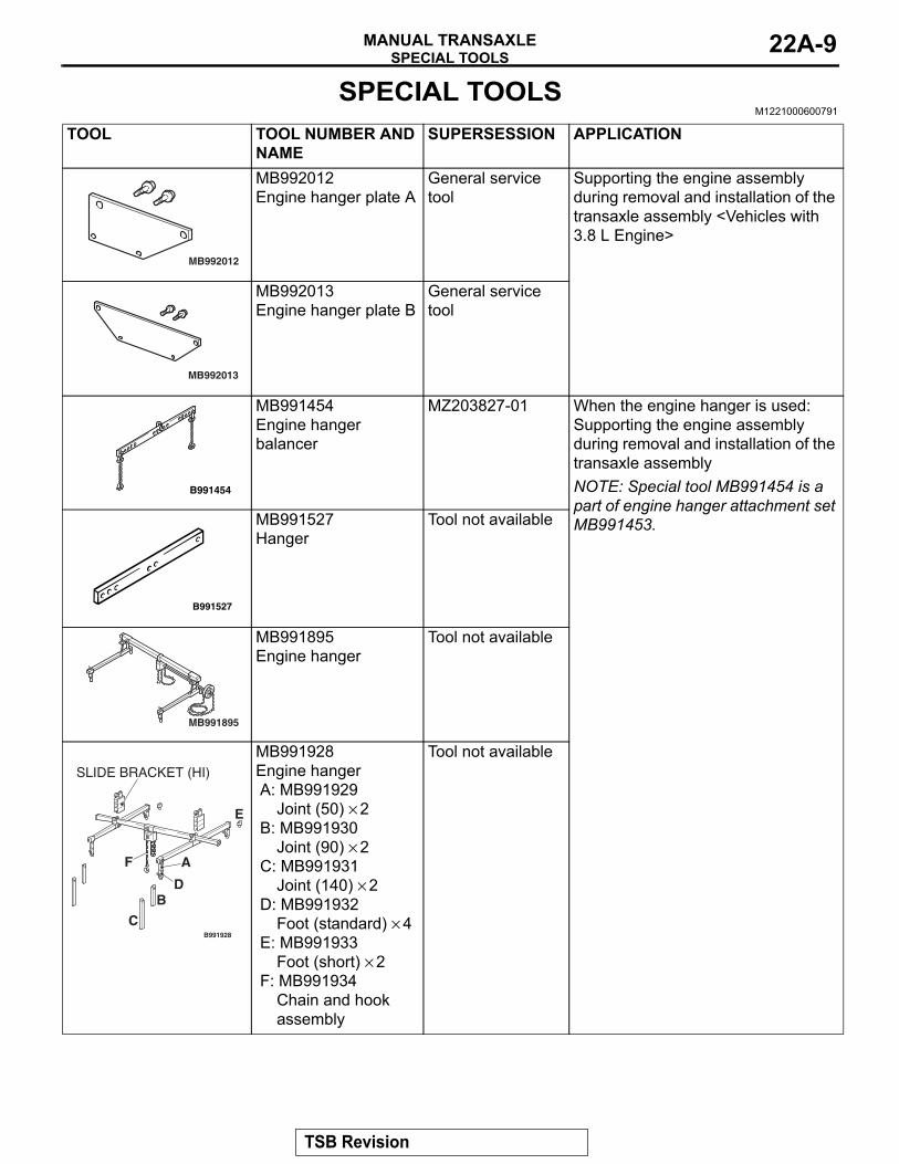
SPECIAL TOOLSM1221000600791
TOOL TOOL NUMBER AND NAME
SUPERSESSION APPLICATION
MB992012
MB992012Engine hanger plate A
General service tool
Supporting the engine assembly during removal and installation of the transaxle assembly <Vehicles with 3.8 L Engine>
MB992013
MB992013Engine hanger plate B
General service tool
B991454
MB991454Engine hanger balancer
MZ203827-01 When the engine hanger is used: Supporting the engine assembly during removal and installation of the transaxle assemblyNOTE: Special tool MB991454 is a part of engine hanger attachment set MB991453.
B991527
MB991527Hanger
Tool not available
MB991895
MB991895Engine hanger
Tool not available
B991928
A
B
C
D
E
F
SLIDE BRACKET (HI)
MB991928Engine hangerA: MB991929
Joint (50) × 2B: MB991930
Joint (90) × 2C: MB991931
Joint (140) × 2D: MB991932
Foot (standard) × 4E: MB991933
Foot (short) × 2F: MB991934
Chain and hook assembly
Tool not available
TSB Revision
ON-VEHICLE SERVICEMANUAL TRANSAXLE22A-10
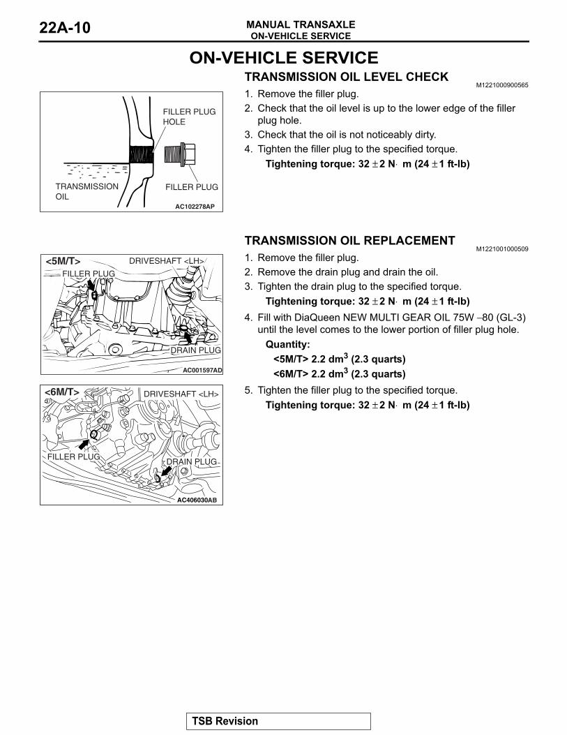
ON-VEHICLE SERVICETRANSMISSION OIL LEVEL CHECK
M1221000900565
AC102278AP
FILLER PLUGTRANSMISSIONOIL
FILLER PLUGHOLE
1. Remove the filler plug.2. Check that the oil level is up to the lower edge of the filler
plug hole.3. Check that the oil is not noticeably dirty.4. Tighten the filler plug to the specified torque.
Tightening torque: 32 ± 2 N⋅ m (24 ± 1 ft-lb)
TRANSMISSION OIL REPLACEMENTM1221001000509
AC001597
DRIVESHAFT <LH>
DRAIN PLUG
FILLER PLUG
AD
<5M/T>
AC406030
DRIVESHAFT <LH>
DRAIN PLUGFILLER PLUG
<6M/T>
AB
1. Remove the filler plug.2. Remove the drain plug and drain the oil.3. Tighten the drain plug to the specified torque.
Tightening torque: 32 ± 2 N⋅ m (24 ± 1 ft-lb)4. Fill with DiaQueen NEW MULTI GEAR OIL 75W − 80 (GL-3)
until the level comes to the lower portion of filler plug hole.Quantity:
<5M/T> 2.2 dm3 (2.3 quarts)<6M/T> 2.2 dm3 (2.3 quarts)
5. Tighten the filler plug to the specified torque.Tightening torque: 32 ± 2 N⋅ m (24 ± 1 ft-lb)
TSB Revision
TRANSAXLE CONTROLMANUAL TRANSAXLE 22A-11
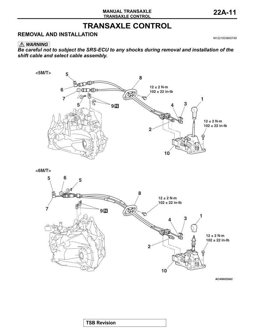
TRANSAXLE CONTROLREMOVAL AND INSTALLATION
M1221003800749
WARNINGBe careful not to subject the SRS-ECU to any shocks during removal and installation of the shift cable and select cable assembly.
AC406035
1
2
34
5
12 ± 2 N·m102 ± 22 in-lb
AC
6
7
8
10
1
2
345
6
7
8
9
10
12 ± 2 N·m102 ± 22 in-lb
12 ± 2 N·m102 ± 22 in-lb
12 ± 2 N·m102 ± 22 in-lb
5
5<5M/T>
N
<6M/T>
9 N
TSB Revision
TRANSAXLE CONTROLMANUAL TRANSAXLE22A-12
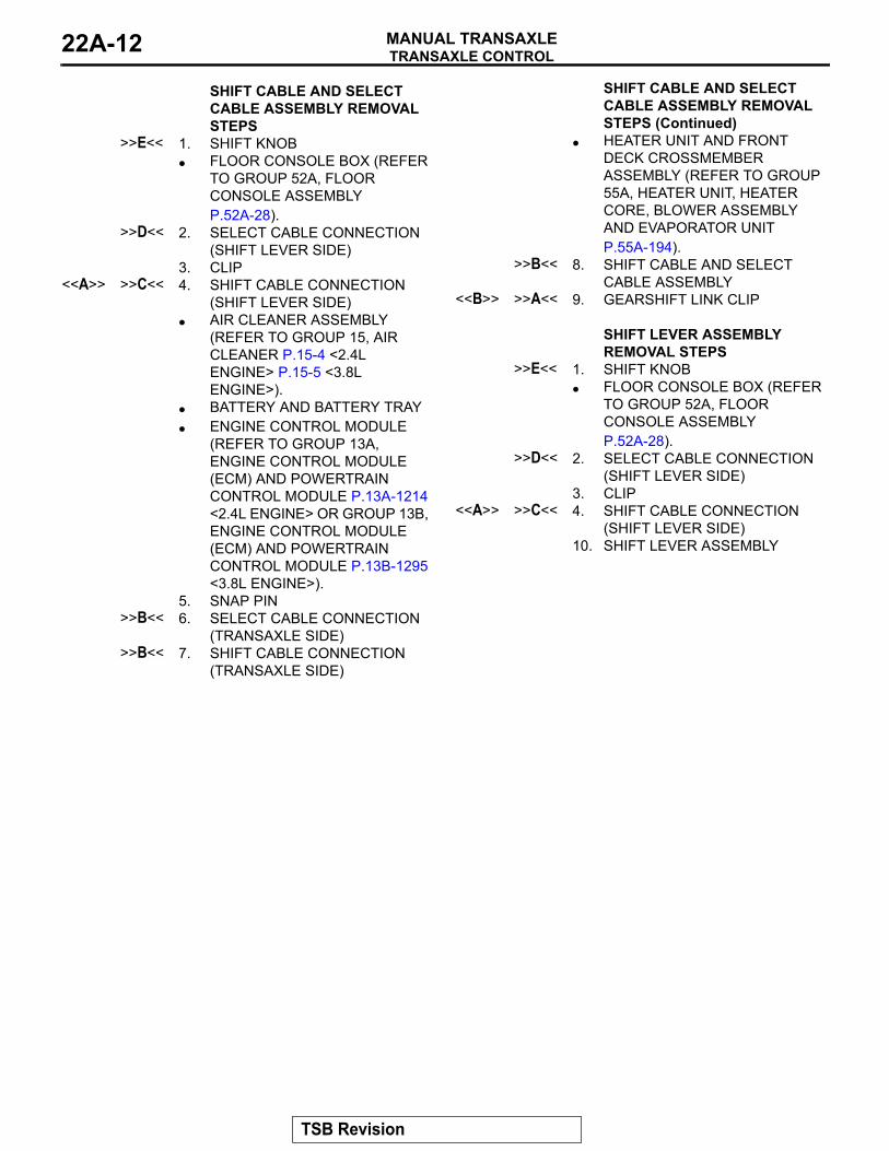
SHIFT CABLE AND SELECT CABLE ASSEMBLY REMOVAL STEPS
>>E<< 1. SHIFT KNOB• FLOOR CONSOLE BOX (REFER
TO GROUP 52A, FLOOR CONSOLE ASSEMBLY P.52A-28).
>>D<< 2. SELECT CABLE CONNECTION (SHIFT LEVER SIDE)
3. CLIP<<A>> >>C<< 4. SHIFT CABLE CONNECTION
(SHIFT LEVER SIDE)• AIR CLEANER ASSEMBLY
(REFER TO GROUP 15, AIR CLEANER P.15-4 <2.4L ENGINE> P.15-5 <3.8L ENGINE>).
• BATTERY AND BATTERY TRAY• ENGINE CONTROL MODULE
(REFER TO GROUP 13A, ENGINE CONTROL MODULE (ECM) AND POWERTRAIN CONTROL MODULE P.13A-1214 <2.4L ENGINE> OR GROUP 13B, ENGINE CONTROL MODULE (ECM) AND POWERTRAIN CONTROL MODULE P.13B-1295 <3.8L ENGINE>).
5. SNAP PIN>>B<< 6. SELECT CABLE CONNECTION
(TRANSAXLE SIDE)>>B<< 7. SHIFT CABLE CONNECTION
(TRANSAXLE SIDE)
• HEATER UNIT AND FRONT DECK CROSSMEMBER ASSEMBLY (REFER TO GROUP 55A, HEATER UNIT, HEATER CORE, BLOWER ASSEMBLY AND EVAPORATOR UNIT P.55A-194).
>>B<< 8. SHIFT CABLE AND SELECT CABLE ASSEMBLY
<<B>> >>A<< 9. GEARSHIFT LINK CLIP SHIFT LEVER ASSEMBLY REMOVAL STEPS
>>E<< 1. SHIFT KNOB• FLOOR CONSOLE BOX (REFER
TO GROUP 52A, FLOOR CONSOLE ASSEMBLY P.52A-28).
>>D<< 2. SELECT CABLE CONNECTION (SHIFT LEVER SIDE)
3. CLIP<<A>> >>C<< 4. SHIFT CABLE CONNECTION
(SHIFT LEVER SIDE)10. SHIFT LEVER ASSEMBLY
SHIFT CABLE AND SELECT CABLE ASSEMBLY REMOVAL STEPS (Continued)
TSB Revision
TRANSAXLE CONTROLMANUAL TRANSAXLE 22A-13
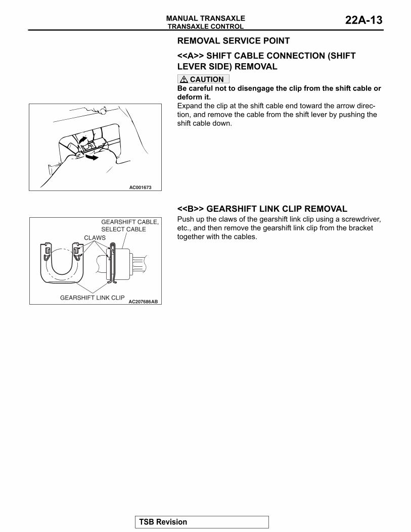
REMOVAL SERVICE POINT.
<<A>> SHIFT CABLE CONNECTION (SHIFT LEVER SIDE) REMOVAL
CAUTIONBe careful not to disengage the clip from the shift cable or deform it.
AC001673
Expand the clip at the shift cable end toward the arrow direc-tion, and remove the cable from the shift lever by pushing the shift cable down.
.
<<B>> GEARSHIFT LINK CLIP REMOVAL
AC207686ABGEARSHIFT LINK CLIP
GEARSHIFT CABLE,SELECT CABLE
CLAWS
Push up the claws of the gearshift link clip using a screwdriver, etc., and then remove the gearshift link clip from the bracket together with the cables.
TSB Revision
TRANSAXLE CONTROLMANUAL TRANSAXLE22A-14
INSTALLATION SERVICE POINTS.
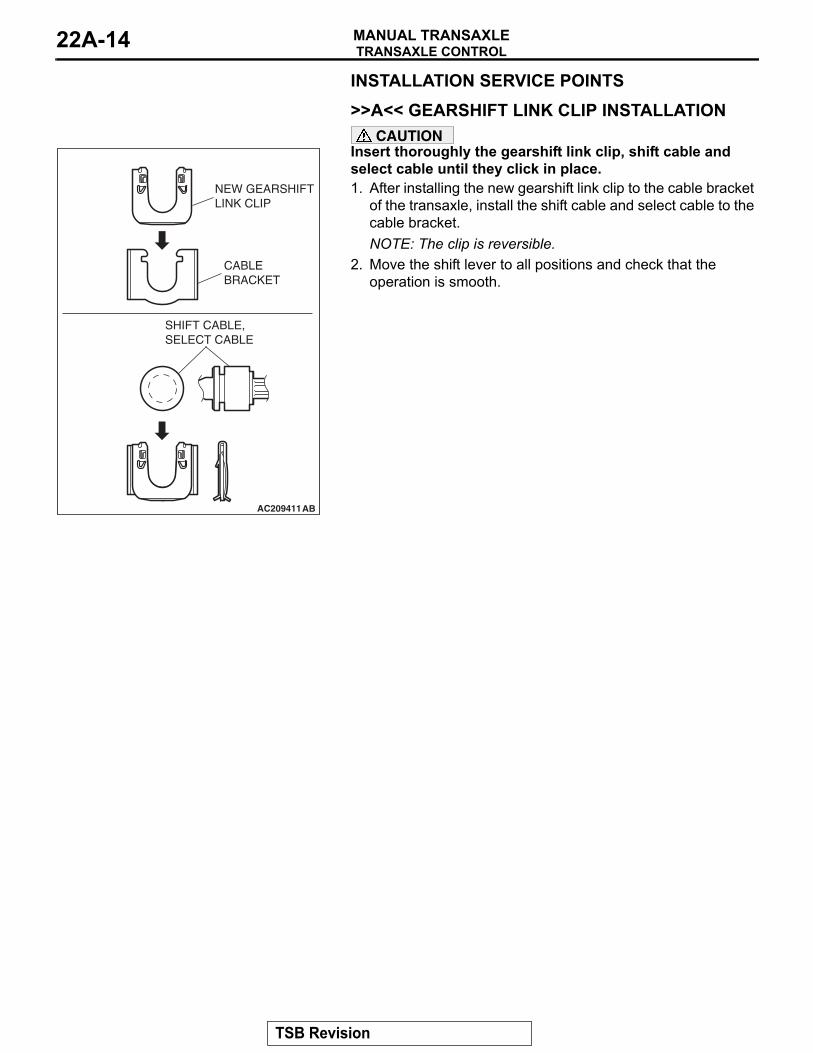
>>A<< GEARSHIFT LINK CLIP INSTALLATION
AC209411AB
NEW GEARSHIFTLINK CLIP
CABLE BRACKET
SHIFT CABLE, SELECT CABLE
CAUTIONInsert thoroughly the gearshift link clip, shift cable and select cable until they click in place.1. After installing the new gearshift link clip to the cable bracket
of the transaxle, install the shift cable and select cable to the cable bracket.NOTE: The clip is reversible.
2. Move the shift lever to all positions and check that the operation is smooth.
.
TSB Revision
TRANSAXLE CONTROLMANUAL TRANSAXLE 22A-15
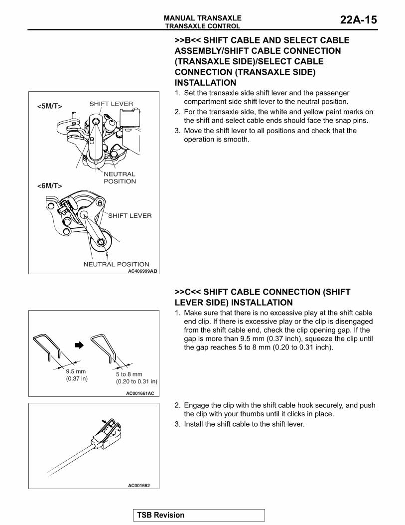
>>B<< SHIFT CABLE AND SELECT CABLE ASSEMBLY/SHIFT CABLE CONNECTION (TRANSAXLE SIDE)/SELECT CABLE CONNECTION (TRANSAXLE SIDE) INSTALLATION
AC406999AB
NEUTRAL POSITION
SHIFT LEVER
NEUTRAL POSITION
SHIFT LEVER
<5M/T>
<6M/T>
1. Set the transaxle side shift lever and the passenger compartment side shift lever to the neutral position.
2. For the transaxle side, the white and yellow paint marks on the shift and select cable ends should face the snap pins.
3. Move the shift lever to all positions and check that the operation is smooth.
.
>>C<< SHIFT CABLE CONNECTION (SHIFT LEVER SIDE) INSTALLATION
AC001661
9.5 mm(0.37 in)
5 to 8 mm(0.20 to 0.31 in)
AC
1. Make sure that there is no excessive play at the shift cable end clip. If there is excessive play or the clip is disengaged from the shift cable end, check the clip opening gap. If the gap is more than 9.5 mm (0.37 inch), squeeze the clip until the gap reaches 5 to 8 mm (0.20 to 0.31 inch).
AC001662
2. Engage the clip with the shift cable hook securely, and push the clip with your thumbs until it clicks in place.
3. Install the shift cable to the shift lever.
.
TSB Revision
TRANSAXLE CONTROLMANUAL TRANSAXLE22A-16
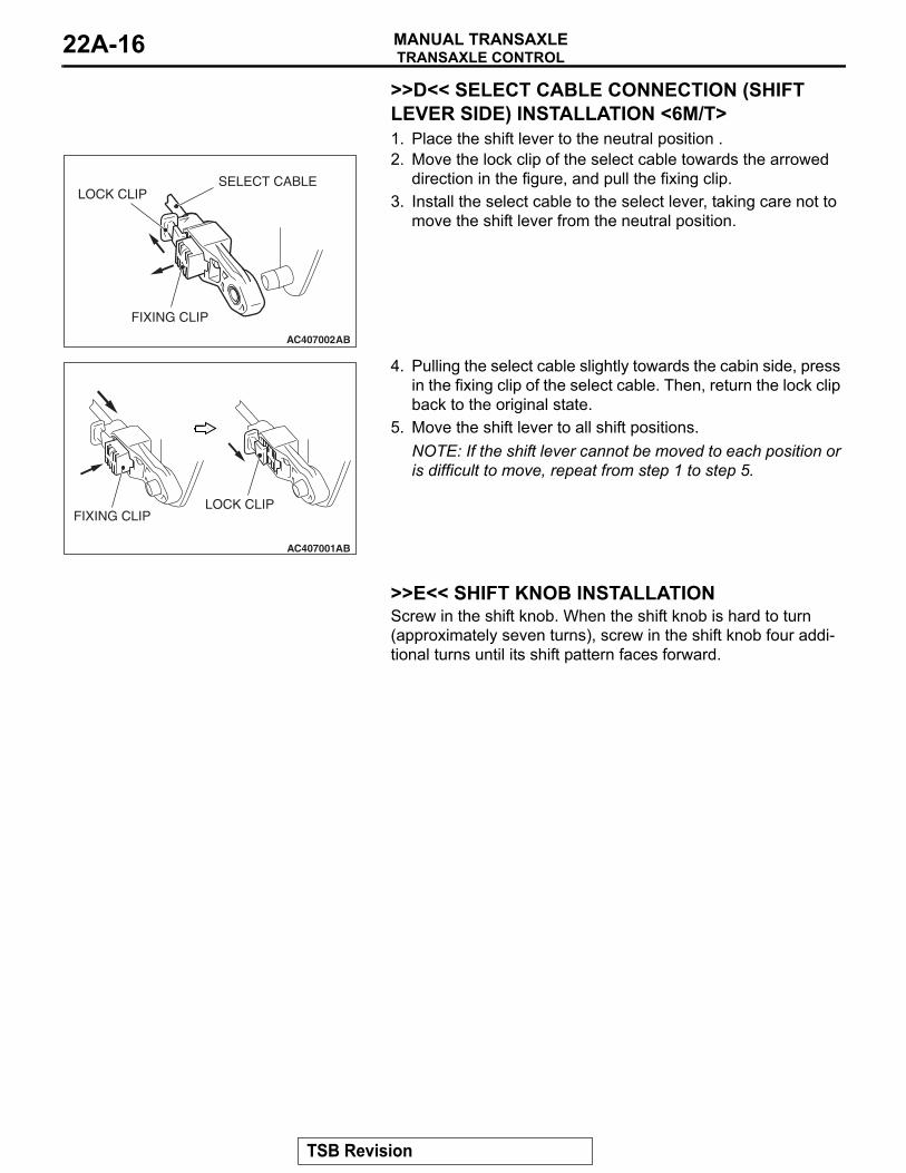
>>D<< SELECT CABLE CONNECTION (SHIFT LEVER SIDE) INSTALLATION <6M/T>1. Place the shift lever to the neutral position .
AC407002AB
SELECT CABLELOCK CLIP
FIXING CLIP
2. Move the lock clip of the select cable towards the arrowed direction in the figure, and pull the fixing clip.
3. Install the select cable to the select lever, taking care not to move the shift lever from the neutral position.
AC407001
FIXING CLIPLOCK CLIP
AB
4. Pulling the select cable slightly towards the cabin side, press in the fixing clip of the select cable. Then, return the lock clip back to the original state.
5. Move the shift lever to all shift positions.NOTE: If the shift lever cannot be moved to each position or is difficult to move, repeat from step 1 to step 5.
.
>>E<< SHIFT KNOB INSTALLATIONScrew in the shift knob. When the shift knob is hard to turn (approximately seven turns), screw in the shift knob four addi-tional turns until its shift pattern faces forward.
TSB Revision
TRANSAXLE ASSEMBLYMANUAL TRANSAXLE 22A-17
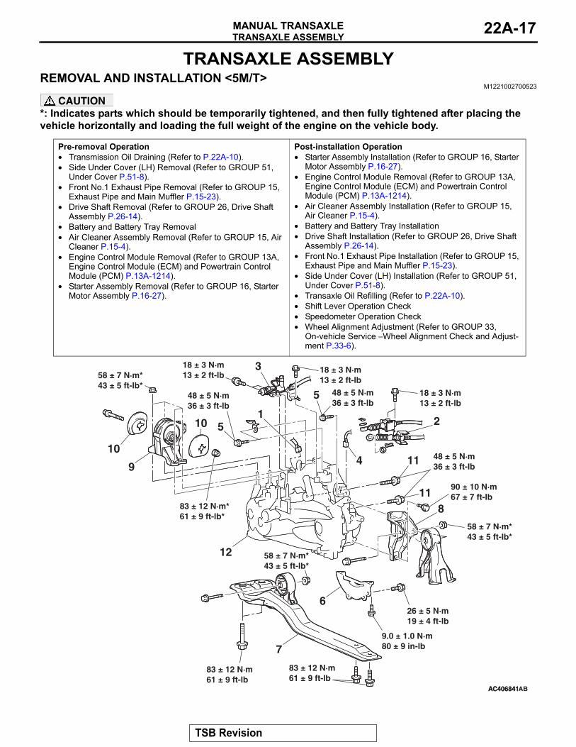
TRANSAXLE ASSEMBLYREMOVAL AND INSTALLATION <5M/T>
M1221002700523
CAUTION*: Indicates parts which should be temporarily tightened, and then fully tightened after placing the vehicle horizontally and loading the full weight of the engine on the vehicle body.
Pre-removal Operation• Transmission Oil Draining (Refer to P.22A-10).• Side Under Cover (LH) Removal (Refer to GROUP 51,
Under Cover P.51-8).• Front No.1 Exhaust Pipe Removal (Refer to GROUP 15,
Exhaust Pipe and Main Muffler P.15-23).• Drive Shaft Removal (Refer to GROUP 26, Drive Shaft
Assembly P.26-14).• Battery and Battery Tray Removal• Air Cleaner Assembly Removal (Refer to GROUP 15, Air
Cleaner P.15-4).• Engine Control Module Removal (Refer to GROUP 13A,
Engine Control Module (ECM) and Powertrain Control Module (PCM) P.13A-1214).
• Starter Assembly Removal (Refer to GROUP 16, Starter Motor Assembly P.16-27).
Post-installation Operation• Starter Assembly Installation (Refer to GROUP 16, Starter
Motor Assembly P.16-27).• Engine Control Module Removal (Refer to GROUP 13A,
Engine Control Module (ECM) and Powertrain Control Module (PCM) P.13A-1214).
• Air Cleaner Assembly Installation (Refer to GROUP 15, Air Cleaner P.15-4).
• Battery and Battery Tray Installation• Drive Shaft Installation (Refer to GROUP 26, Drive Shaft
Assembly P.26-14).• Front No.1 Exhaust Pipe Installation (Refer to GROUP 15,
Exhaust Pipe and Main Muffler P.15-23).• Side Under Cover (LH) Installation (Refer to GROUP 51,
Under Cover P.51-8).• Transaxle Oil Refilling (Refer to P.22A-10).• Shift Lever Operation Check• Speedometer Operation Check• Wheel Alignment Adjustment (Refer to GROUP 33,
On-vehicle Service − Wheel Alignment Check and Adjust-ment P.33-6).
AC406841AC406841
12
3
4
5
5
6
7
8
9
10
10
11
11
12
9.0 ± 1.0 N·m80 ± 9 in-lb
26 ± 5 N·m19 ± 4 ft-lb
AB
83 ± 12 N·m61 ± 9 ft-lb
83 ± 12 N·m61 ± 9 ft-lb
18 ± 3 N·m13 ± 2 ft-lb
18 ± 3 N·m13 ± 2 ft-lb
58 ± 7 N·m*43 ± 5 ft-lb*
58 ± 7 N·m*43 ± 5 ft-lb*
18 ± 3 N·m13 ± 2 ft-lb
48 ± 5 N·m36 ± 3 ft-lb
90 ± 10 N·m67 ± 7 ft-lb
58 ± 7 N·m*43 ± 5 ft-lb*
48 ± 5 N·m36 ± 3 ft-lb
48 ± 5 N·m36 ± 3 ft-lb
83 ± 12 N·m*61 ± 9 ft-lb*
TSB Revision
TRANSAXLE ASSEMBLYMANUAL TRANSAXLE22A-18
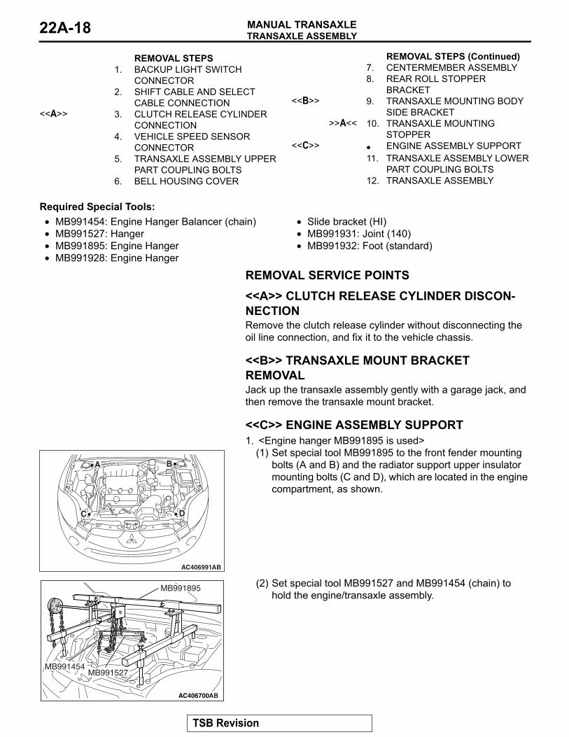
REMOVAL STEPS 1. BACKUP LIGHT SWITCH
CONNECTOR2. SHIFT CABLE AND SELECT
CABLE CONNECTION<<A>> 3. CLUTCH RELEASE CYLINDER
CONNECTION4. VEHICLE SPEED SENSOR
CONNECTOR5. TRANSAXLE ASSEMBLY UPPER
PART COUPLING BOLTS6. BELL HOUSING COVER
7. CENTERMEMBER ASSEMBLY8. REAR ROLL STOPPER
BRACKET<<B>> 9. TRANSAXLE MOUNTING BODY
SIDE BRACKET>>A<< 10. TRANSAXLE MOUNTING
STOPPER<<C>> • ENGINE ASSEMBLY SUPPORT
11. TRANSAXLE ASSEMBLY LOWER PART COUPLING BOLTS
12. TRANSAXLE ASSEMBLY
Required Special Tools:• MB991454: Engine Hanger Balancer (chain)• MB991527: Hanger• MB991895: Engine Hanger• MB991928: Engine Hanger
• Slide bracket (HI)• MB991931: Joint (140)• MB991932: Foot (standard)
REMOVAL SERVICE POINTS.
<<A>> CLUTCH RELEASE CYLINDER DISCON-NECTIONRemove the clutch release cylinder without disconnecting the oil line connection, and fix it to the vehicle chassis..
<<B>> TRANSAXLE MOUNT BRACKET REMOVALJack up the transaxle assembly gently with a garage jack, and then remove the transaxle mount bracket..
<<C>> ENGINE ASSEMBLY SUPPORT1. <Engine hanger MB991895 is used>
AC406991AB
A B
C D
(1) Set special tool MB991895 to the front fender mounting bolts (A and B) and the radiator support upper insulator mounting bolts (C and D), which are located in the engine compartment, as shown.
AC406700
MB991527MB991454
MB991895
AB
(2) Set special tool MB991527 and MB991454 (chain) to hold the engine/transaxle assembly.
REMOVAL STEPS (Continued)
TSB Revision
TRANSAXLE ASSEMBLYMANUAL TRANSAXLE 22A-19
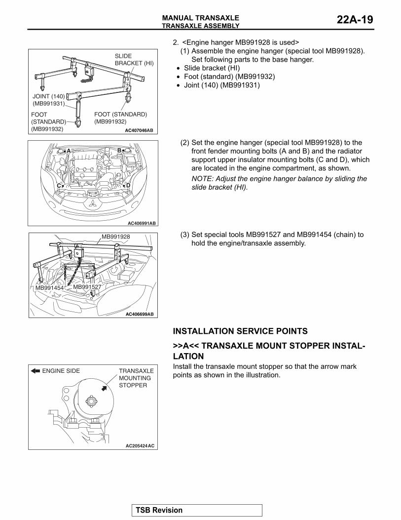
2. <Engine hanger MB991928 is used>
AC407046AB
JOINT (140)(MB991931)
FOOT (STANDARD)(MB991932)
FOOT (STANDARD)(MB991932)
SLIDE BRACKET (HI)
(1) Assemble the engine hanger (special tool MB991928). Set following parts to the base hanger.
• Slide bracket (HI)• Foot (standard) (MB991932)•
AC406991AB
A B
C D
Joint (140) (MB991931)
(2) Set the engine hanger (special tool MB991928) to the front fender mounting bolts (A and B) and the radiator support upper insulator mounting bolts (C and D), which are located in the engine compartment, as shown.NOTE: Adjust the engine hanger balance by sliding the slide bracket (HI).
AC406699AB
MB991928
MB991527MB991454
(3) Set special tools MB991527 and MB991454 (chain) to hold the engine/transaxle assembly.
INSTALLATION SERVICE POINTS.
>>A<< TRANSAXLE MOUNT STOPPER INSTAL-LATION
AC205424
ENGINE SIDE TRANSAXLE MOUNTING STOPPER
AC
Install the transaxle mount stopper so that the arrow mark points as shown in the illustration.
TSB Revision
TRANSAXLE ASSEMBLYMANUAL TRANSAXLE22A-20
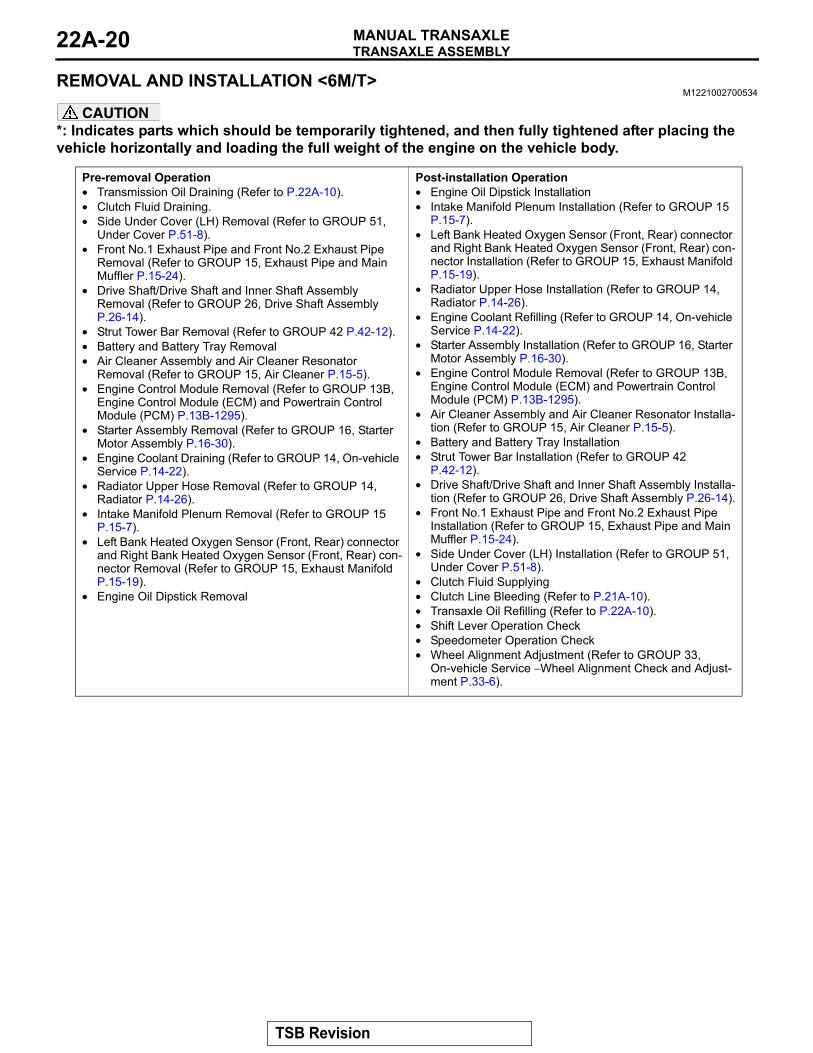
REMOVAL AND INSTALLATION <6M/T>M1221002700534
CAUTION*: Indicates parts which should be temporarily tightened, and then fully tightened after placing the vehicle horizontally and loading the full weight of the engine on the vehicle body.
Pre-removal Operation• Transmission Oil Draining (Refer to P.22A-10).• Clutch Fluid Draining.• Side Under Cover (LH) Removal (Refer to GROUP 51,
Under Cover P.51-8).• Front No.1 Exhaust Pipe and Front No.2 Exhaust Pipe
Removal (Refer to GROUP 15, Exhaust Pipe and Main Muffler P.15-24).
• Drive Shaft/Drive Shaft and Inner Shaft Assembly Removal (Refer to GROUP 26, Drive Shaft Assembly P.26-14).
• Strut Tower Bar Removal (Refer to GROUP 42 P.42-12).• Battery and Battery Tray Removal• Air Cleaner Assembly and Air Cleaner Resonator
Removal (Refer to GROUP 15, Air Cleaner P.15-5).• Engine Control Module Removal (Refer to GROUP 13B,
Engine Control Module (ECM) and Powertrain Control Module (PCM) P.13B-1295).
• Starter Assembly Removal (Refer to GROUP 16, Starter Motor Assembly P.16-30).
• Engine Coolant Draining (Refer to GROUP 14, On-vehicle Service P.14-22).
• Radiator Upper Hose Removal (Refer to GROUP 14, Radiator P.14-26).
• Intake Manifold Plenum Removal (Refer to GROUP 15 P.15-7).
• Left Bank Heated Oxygen Sensor (Front, Rear) connector and Right Bank Heated Oxygen Sensor (Front, Rear) con-nector Removal (Refer to GROUP 15, Exhaust Manifold P.15-19).
• Engine Oil Dipstick Removal
Post-installation Operation• Engine Oil Dipstick Installation• Intake Manifold Plenum Installation (Refer to GROUP 15
P.15-7).• Left Bank Heated Oxygen Sensor (Front, Rear) connector
and Right Bank Heated Oxygen Sensor (Front, Rear) con-nector Installation (Refer to GROUP 15, Exhaust Manifold P.15-19).
• Radiator Upper Hose Installation (Refer to GROUP 14, Radiator P.14-26).
• Engine Coolant Refilling (Refer to GROUP 14, On-vehicle Service P.14-22).
• Starter Assembly Installation (Refer to GROUP 16, Starter Motor Assembly P.16-30).
• Engine Control Module Removal (Refer to GROUP 13B, Engine Control Module (ECM) and Powertrain Control Module (PCM) P.13B-1295).
• Air Cleaner Assembly and Air Cleaner Resonator Installa-tion (Refer to GROUP 15, Air Cleaner P.15-5).
• Battery and Battery Tray Installation• Strut Tower Bar Installation (Refer to GROUP 42
P.42-12).• Drive Shaft/Drive Shaft and Inner Shaft Assembly Installa-
tion (Refer to GROUP 26, Drive Shaft Assembly P.26-14).• Front No.1 Exhaust Pipe and Front No.2 Exhaust Pipe
Installation (Refer to GROUP 15, Exhaust Pipe and Main Muffler P.15-24).
• Side Under Cover (LH) Installation (Refer to GROUP 51, Under Cover P.51-8).
• Clutch Fluid Supplying• Clutch Line Bleeding (Refer to P.21A-10).• Transaxle Oil Refilling (Refer to P.22A-10).• Shift Lever Operation Check• Speedometer Operation Check• Wheel Alignment Adjustment (Refer to GROUP 33,
On-vehicle Service − Wheel Alignment Check and Adjust-ment P.33-6).
TSB Revision
TRANSAXLE ASSEMBLYMANUAL TRANSAXLE 22A-21
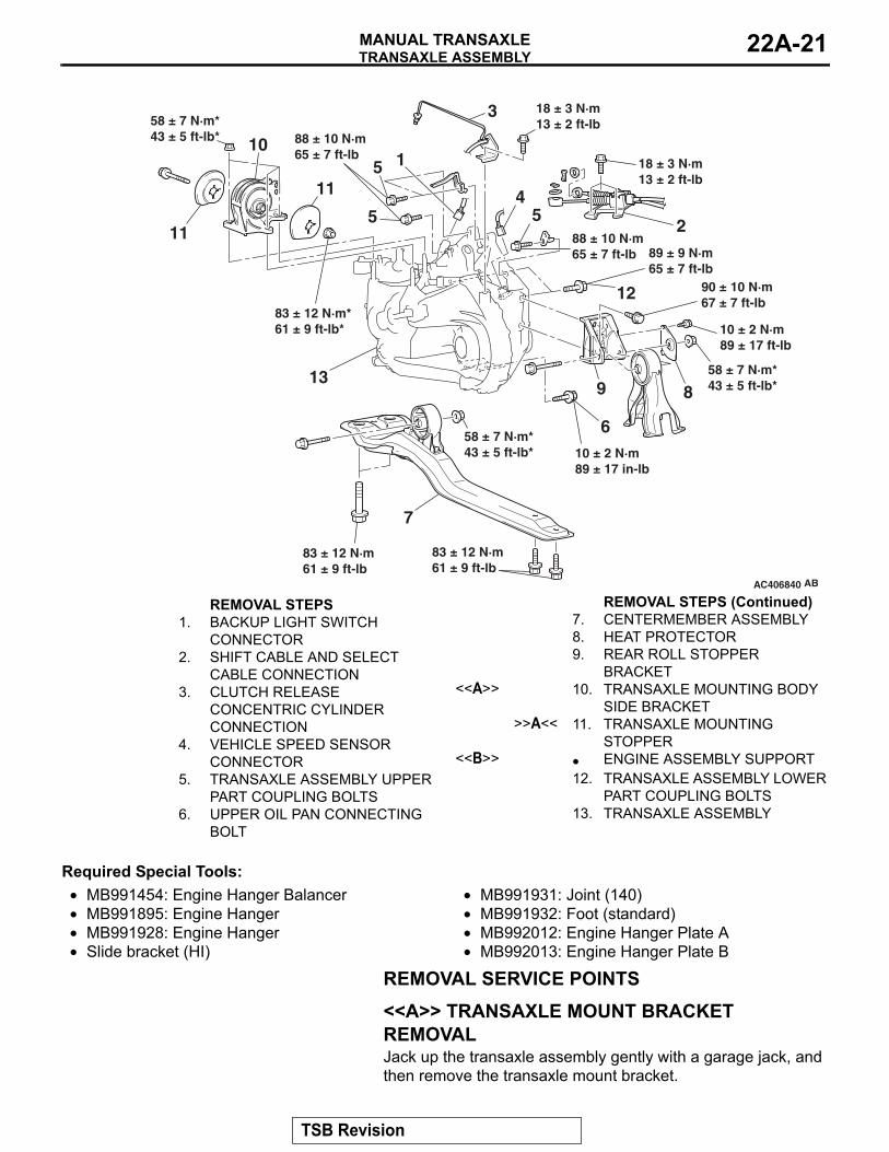
AC406840
1
2
3
45 5
6
7
8913
10
11
11
12
AB
83 ± 12 N·m61 ± 9 ft-lb
83 ± 12 N·m61 ± 9 ft-lb
18 ± 3 N·m13 ± 2 ft-lb
58 ± 7 N·m*43 ± 5 ft-lb*
58 ± 7 N·m*43 ± 5 ft-lb*
18 ± 3 N·m13 ± 2 ft-lb
89 ± 9 N·m65 ± 7 ft-lb
90 ± 10 N·m67 ± 7 ft-lb
58 ± 7 N·m*43 ± 5 ft-lb*
88 ± 10 N·m65 ± 7 ft-lb
88 ± 10 N·m65 ± 7 ft-lb
83 ± 12 N·m*61 ± 9 ft-lb*
10 ± 2 N·m89 ± 17 in-lb
10 ± 2 N·m89 ± 17 ft-lb
5
REMOVAL STEPS 1. BACKUP LIGHT SWITCH
CONNECTOR2. SHIFT CABLE AND SELECT
CABLE CONNECTION3. CLUTCH RELEASE
CONCENTRIC CYLINDER CONNECTION
4. VEHICLE SPEED SENSOR CONNECTOR
5. TRANSAXLE ASSEMBLY UPPER PART COUPLING BOLTS
6. UPPER OIL PAN CONNECTING BOLT
7. CENTERMEMBER ASSEMBLY8. HEAT PROTECTOR9. REAR ROLL STOPPER
BRACKET<<A>> 10. TRANSAXLE MOUNTING BODY
SIDE BRACKET>>A<< 11. TRANSAXLE MOUNTING
STOPPER<<B>> • ENGINE ASSEMBLY SUPPORT
12. TRANSAXLE ASSEMBLY LOWER PART COUPLING BOLTS
13. TRANSAXLE ASSEMBLY
Required Special Tools:• MB991454: Engine Hanger Balancer• MB991895: Engine Hanger• MB991928: Engine Hanger• Slide bracket (HI)
• MB991931: Joint (140)• MB991932: Foot (standard)• MB992012: Engine Hanger Plate A• MB992013: Engine Hanger Plate B
REMOVAL SERVICE POINTS.
<<A>> TRANSAXLE MOUNT BRACKET REMOVALJack up the transaxle assembly gently with a garage jack, and then remove the transaxle mount bracket..
REMOVAL STEPS (Continued)
TSB Revision
TRANSAXLE ASSEMBLYMANUAL TRANSAXLE22A-22
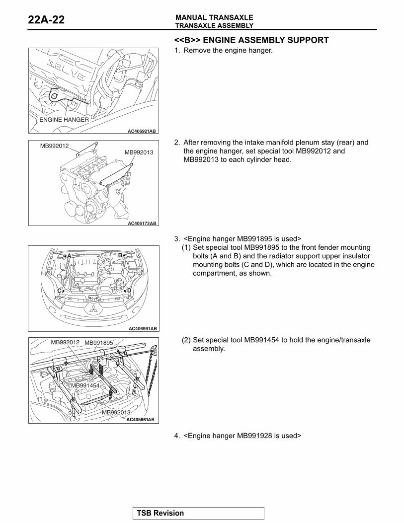
<<B>> ENGINE ASSEMBLY SUPPORT
AC406921AB
ENGINE HANGER
1. Remove the engine hanger.
AC406173AB
MB992012MB992013
2. After removing the intake manifold plenum stay (rear) and the engine hanger, set special tool MB992012 and MB992013 to each cylinder head.
3. <Engine hanger MB991895 is used>
AC406991AB
A B
C D
(1) Set special tool MB991895 to the front fender mounting bolts (A and B) and the radiator support upper insulator mounting bolts (C and D), which are located in the engine compartment, as shown.
AC405861AB
MB992012
MB991454
MB992013
MB991895 (2) Set special tool MB991454 to hold the engine/transaxle assembly.
4. <Engine hanger MB991928 is used>
TSB Revision
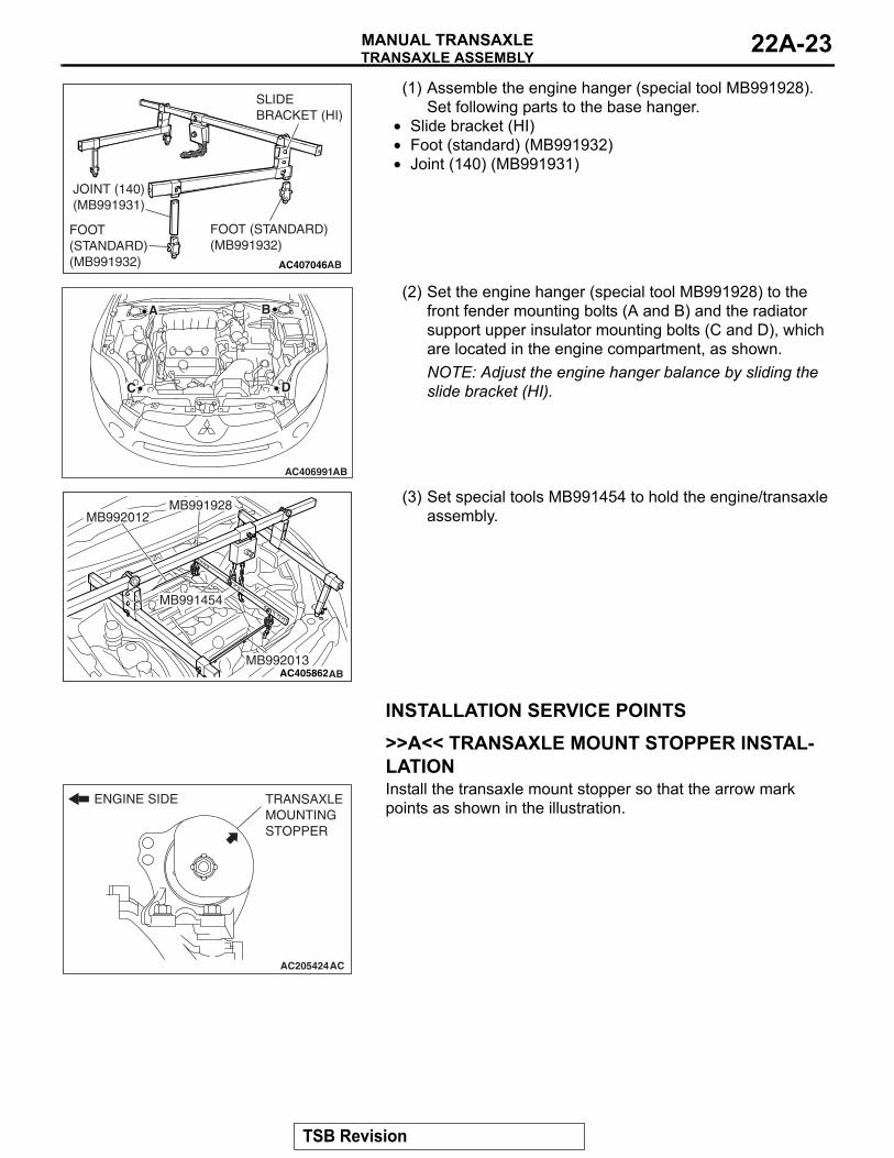
TRANSAXLE ASSEMBLYMANUAL TRANSAXLE 22A-23
AC407046AB
JOINT (140)(MB991931)
FOOT (STANDARD)(MB991932)
FOOT (STANDARD)(MB991932)
SLIDE BRACKET (HI)
(1) Assemble the engine hanger (special tool MB991928). Set following parts to the base hanger.
• Slide bracket (HI)• Foot (standard) (MB991932)•
AC406991AB
A B
C D
Joint (140) (MB991931)
(2) Set the engine hanger (special tool MB991928) to the front fender mounting bolts (A and B) and the radiator support upper insulator mounting bolts (C and D), which are located in the engine compartment, as shown.NOTE: Adjust the engine hanger balance by sliding the slide bracket (HI).
AC405862AB
MB991454
MB992013
MB991928MB992012
(3) Set special tools MB991454 to hold the engine/transaxle assembly.
INSTALLATION SERVICE POINTS.
>>A<< TRANSAXLE MOUNT STOPPER INSTAL-LATION
AC205424
ENGINE SIDE TRANSAXLE MOUNTING STOPPER
AC
Install the transaxle mount stopper so that the arrow mark points as shown in the illustration.
TSB Revision
SPECIFICATIONSMANUAL TRANSAXLE22A-24
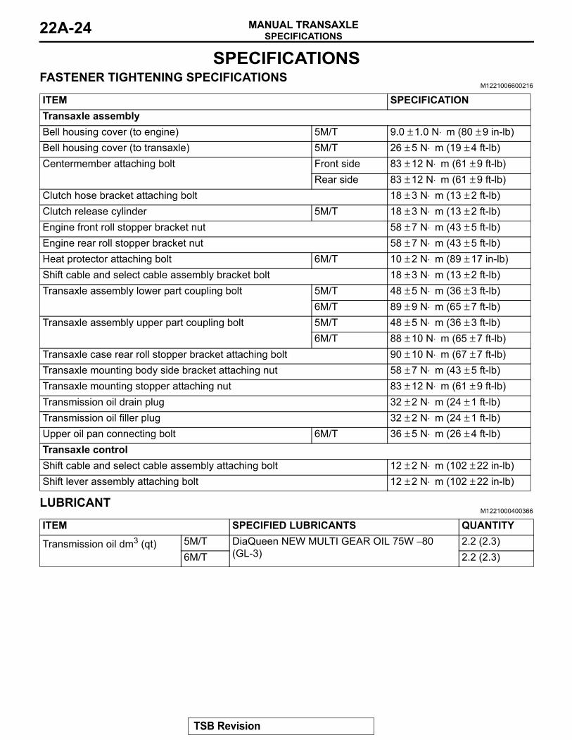
SPECIFICATIONSFASTENER TIGHTENING SPECIFICATIONS
M1221006600216
ITEM SPECIFICATIONTransaxle assemblyBell housing cover (to engine) 5M/T 9.0 ± 1.0 N⋅ m (80 ± 9 in-lb)Bell housing cover (to transaxle) 5M/T 26 ± 5 N⋅ m (19 ± 4 ft-lb)Centermember attaching bolt Front side 83 ± 12 N⋅ m (61 ± 9 ft-lb)
Rear side 83 ± 12 N⋅ m (61 ± 9 ft-lb)Clutch hose bracket attaching bolt 18 ± 3 N⋅ m (13 ± 2 ft-lb)Clutch release cylinder 5M/T 18 ± 3 N⋅ m (13 ± 2 ft-lb)Engine front roll stopper bracket nut 58 ± 7 N⋅ m (43 ± 5 ft-lb)Engine rear roll stopper bracket nut 58 ± 7 N⋅ m (43 ± 5 ft-lb)Heat protector attaching bolt 6M/T 10 ± 2 N⋅ m (89 ± 17 in-lb)Shift cable and select cable assembly bracket bolt 18 ± 3 N⋅ m (13 ± 2 ft-lb)Transaxle assembly lower part coupling bolt 5M/T 48 ± 5 N⋅ m (36 ± 3 ft-lb)
6M/T 89 ± 9 N⋅ m (65 ± 7 ft-lb)Transaxle assembly upper part coupling bolt 5M/T 48 ± 5 N⋅ m (36 ± 3 ft-lb)
6M/T 88 ± 10 N⋅ m (65 ± 7 ft-lb)Transaxle case rear roll stopper bracket attaching bolt 90 ± 10 N⋅ m (67 ± 7 ft-lb)Transaxle mounting body side bracket attaching nut 58 ± 7 N⋅ m (43 ± 5 ft-lb)Transaxle mounting stopper attaching nut 83 ± 12 N⋅ m (61 ± 9 ft-lb)Transmission oil drain plug 32 ± 2 N⋅ m (24 ± 1 ft-lb)Transmission oil filler plug 32 ± 2 N⋅ m (24 ± 1 ft-lb)Upper oil pan connecting bolt 6M/T 36 ± 5 N⋅ m (26 ± 4 ft-lb)Transaxle controlShift cable and select cable assembly attaching bolt 12 ± 2 N⋅ m (102 ± 22 in-lb)Shift lever assembly attaching bolt 12 ± 2 N⋅ m (102 ± 22 in-lb)
LUBRICANTM1221000400366
ITEM SPECIFIED LUBRICANTS QUANTITY
Transmission oil dm3 (qt) 5M/T DiaQueen NEW MULTI GEAR OIL 75W − 80 (GL-3)
2.2 (2.3)6M/T 2.2 (2.3)
TSB Revision