
GREENHOUSE GAS EMISSIONS REPORTING FROM THE PETROLEUM AND
144
GREENHOUSE GAS EMISSIONS REPORTING FROM THE PETROLEUM AND NATURAL GAS INDUSTRY BACKGROUND TECHNICAL SUPPORT DOCUMENT The Environmental Protection Agency (EPA) regulations cited in this technical support document (TSD) contain legally-binding requirements. In several chapters this TSD offers illustrative examples for complying with the minimum requirements indicated by the regulations. This is done to provide information that may be helpful for reporters’ implementation efforts. Such recommendations are prefaced by the words “may” or “should” and are to be considered advisory. They are not required elements of the regulations cited in this TSD. Therefore, this document does not substitute for the regulations cited in this TSD, nor is it a regulation itself, so it does not impose legally-binding requirements on EPA or the regulated community. It may not apply to a particular situation based upon the circumstances. Mention of trade names or commercial products does not constitute endorsement or recommendation for use. While EPA has made every effort to ensure the accuracy of the discussion in this document, the obligations of the regulated community are determined by statutes, regulations or other legally binding requirements. In the event of a conflict between the discussion in this document and any statute or regulation, this document would not be controlling. U.S. ENVIRONMENTAL PROTECTION AGENCY CLIMATE CHANGE DIVISION WASHINGTON DC
Transcript of GREENHOUSE GAS EMISSIONS REPORTING FROM THE PETROLEUM AND
GREENHOUSE GAS EMISSIONS REPORTING FROM THE PETROLEUM AND NATURAL GAS INDUSTRY
BACKGROUND TECHNICAL SUPPORT DOCUMENT
The Environmental Protection Agency (EPA) regulations cited in this technical support document (TSD) contain legally-binding requirements In several chapters this TSD offers illustrative examples for complying with the minimum requirements indicated by the regulations This is done to provide information that may be helpful for reportersrsquo implementation efforts Such recommendations are prefaced by the words ldquomayrdquo or ldquoshouldrdquo and are to be considered advisory They are not required elements of the regulations cited in this TSD Therefore this document does not substitute for the regulations cited in this TSD nor is it a regulation itself so it does not impose legally-binding requirements on EPA or the regulated community It may not apply to a particular situation based upon the circumstances Mention of trade names or commercial products does not constitute endorsement or recommendation for use
While EPA has made every effort to ensure the accuracy of the discussion in this document the obligations of the regulated community are determined by statutes regulations or other legally binding requirements In the event of a conflict between the discussion in this document and any statute or regulation this document would not be controlling
US ENVIRONMENTAL PROTECTION AGENCY CLIMATE CHANGE DIVISION WASHINGTON DC
TABLE OF CONTENTS 1 Segments in the Petroleum and Natural Gas Industry 4
a Petroleum Industry 4 b Natural Gas Industry 5
2 Types of Emissions Sources and GHGs 6 3 GHG Emissions from the Petroleum and Natural Gas Industry 7 4 Methodology for Selection of Industry Segments and Emissions Sources Feasible for
Inclusion in a GHG Reporting Rule 10 a Review of Existing Regulations 11 b Review of Existing Programs and Studies 12 c Selection of Emissions Sources for Reporting 19
i Facility Definition Characterization 19 ii Selection of Potential Emissions Sources for Reporting 20 iii Address Sources with Large Uncertainties 24 iv Identify Industry Segments to be Included 25
5 Options for Reporting Threshold 27 a Threshold Analysis 28
6 Monitoring Method Options 33 a Review of Existing Relevant Reporting Programs Methodologies 33 b Potential Monitoring Methods 33
i Equipment Leak Detection 33 ii Emissions Measurement 36
A Direct Measurement 36 B Engineering Estimation and Emission Factors 39 C Emission Factors 47 D Combination of Direct Measurement and Engineering Estimation 47
c Leak detection and leaker emission factors 63 d Population Count and Emission Factors 63 e Method 21 64 f Portable VOC Detection Instruments for Leak Measurement 66 g Mass Balance for Quantification 66 h Gulf Offshore Activity Data System program (GOADS) 67 i Additional Questions Regarding Potential Monitoring Methods 67
i Source Level Equipment Leak Detection Threshold 67 ii Duration of Equipment Leaks 69 iii Equipment Leak and Vented Emissions at Different Operational Modes 69 iv Natural Gas Composition 70 v Physical Access for Leak Measurement 71
7 Procedures for Estimating Missing Data 71 a Emissions Measurement Data 72 b Engineering Estimation Data 72 c Emissions Estimation Data for Storage Tanks and Flares 72 d Emissions Estimation Data Using Emissions Factors 73
8 QAQC Requirements 73
Background Technical Support Document ndash Petroleum and Natural Gas Industry 2
a Equipment Maintenance 73 b Data Management 73 c Calculation checks 74
9 Reporting Procedure 75 10 Verification of Reported Emissions 75
Appendix B Development of revised estimates for four UG GHG Inventory emissions
Appendix D Analysis of potential facility definitions for onshore petroleum and natural gas
Appendix E Development of multipliers to scale emissions or miscellaneous sources
Appendix A Segregation of Emissions Sources using the Decision Process 76
sources 84 Appendix C Development of threshold analysis 92
production 106
connected to storage tanks 110 Appendix F Development of leaker emission Factors 113 Appendix G Development of population emission factors 123 Appendix H Glossary 134 Appendix I References 141
Background Technical Support Document ndash Petroleum and Natural Gas Industry 3
1 Segments in the Petroleum and Natural Gas Industry
The US petroleum and natural gas industry encompasses the production of raw gas and crude oil from wells to the delivery of processed gas and petroleum products to consumers These segments use energy and emit greenhouse gases (GHG) It is convenient to view the industry in the following discrete segments
Petroleum Industry ndash petroleum production petroleum transportation petroleum refining petroleum storage terminals and
Natural Gas Industry ndashnatural gas production natural gas gathering and boosting (natural gas gathering and boosting are not included in this rulemaking) natural gas processing natural gas transmission and underground storage liquefied natural gas (LNG) import and export terminals and natural gas distribution
Each industry segment uses common processes and equipment in its facilities most of which emit GHG Each of these industry segments is described in further detail below
a Petroleum Industry
Petroleum Production Petroleum or crude oil is produced from underground geologic formations In some cases natural gas is also produced from oil production wells this gas is called associated natural gas Production may require pumps or compressors for the injection of liquids or gas into the well to maintain production pressure The produced crude oil is typically separated from water and gas injected with chemicals heated and temporarily stored GHG emissions from crude oil production result from combustion-related activities and equipment leaks and vented emissions Equipment counts and GHG-emitting practices are related to the number of producing crude oil wells and their production rates
As petroleum production matures in a field the natural reservoir pressure is not sufficient to bring the petroleum to the surface In such cases enhanced oil recovery (EOR) techniques are used to extract oil that otherwise can not be produced using only reservoir pressure In the United States there are three predominant types of EOR operations currently used thermal EOR gas injection EOR and chemical injection EOR Thermal EOR is carried out by injecting steam into the reservoir to reduce the viscosity of heavy petroleum to allow the flow of the petroleum in the reservoir and up the production well Gas injection EOR involves injecting of gases such as natural gas nitrogen or carbon dioxide (CO2) to decrease the viscosity of the petroleum and push it towards and up the producing well Chemical injection EOR is carried out by injecting surfactants or polymers to improve the flow of petroleum andor enhance a water flood in the reservoir Emissions sources from EOR operations are similar to those in conventional petroleum production fields However additional emissions occur when CO2 is used for recovery This specific EOR operation requires pumps to inject supercritical CO2 into the reservoir while compressors maintain the recycled CO2rsquos supercritical state Venting from these two emissions sources is a major source of emissions
Background Technical Support Document ndash Petroleum and Natural Gas Industry 4
Petroleum Transportation The crude oil stored at production sites is either pumped into crude oil transportation pipelines or loaded onto tankers andor rail freight Along the supply chain crude oil may be stored several times in tanks These operational practices and storage tanks release mainly process GHG emissions Emissions are related to the amount of crude oil transported and the transportation mode
Petroleum Refining Crude oil is delivered to refineries where it is temporarily stored before being fractionated by distillation and treated The fractions are reformed or cracked and then blended into consumer petroleum products such as gasoline diesel aviation fuel kerosene fuel oil and asphalt These processes are energy intensive Equipment counts and GHG gas emitting practices are related to the number and complexity of refineries Subpart Y of the GHG reporting rule (40 CFR Part 98) published in the Federal Register on October 30 2009 addresses refineries and hence is not discussed further in this document
Petroleum products are then transported via trucks rail cars and barges across the supply chain network to terminals and finally to end users
b Natural Gas Industry
Natural Gas Production In natural gas production wells are used to withdraw raw gas from underground formations Wells must be drilled to access the underground formations and often require natural gas well completion procedures or other practices that vent gas from the well depending on the underground formation The produced raw gas commonly requires treatment in the form of separation of gasliquids heating chemical injection and dehydration before being compressed and injected into gathering lines Combustion emissions equipment leaks and vented emissions arise from the wells themselves gathering pipelines and all well-site natural gas treatment processes and related equipment and control devices Determining emissions equipment counts and frequency of GHG emitting practices is related to the number of producing wellheads and the amount of produced natural gas Further details are provided on the individual sources of GHG emissions in Appendix A
Natural Gas Processing In the processing facility natural gas liquids and various other constituents from the raw gas are separated resulting in ldquopipeline qualityrdquo gas that is compressed and injected into the transmission pipelines These separation processes include acid gas removal dehydration and fractionation Most equipment and practices have associated GHG equipment leaks energy consumption-related combustion GHG emissions andor process control related GHG vented emissions Equipment counts and frequency of GHG emitting practices are related to the number and size of gas processing facilities Further details are provided on the individual sources of GHG emissions in Appendix A
Natural Gas Transmission and Storage Natural gas transmission involves high pressure large diameter pipelines that transport natural gas from petroleum and natural gas production sites and natural gas processing facilities to natural gas distribution pipelines or large volume customers such as power plants or chemical plants Compressor station facilities containing
Background Technical Support Document ndash Petroleum and Natural Gas Industry 5
large reciprocating and or centrifugal compressors move the gas throughout the US transmission pipeline system Equipment counts and frequency of GHG emitting practices are related to the number and size of compressor stations and the length of transmission pipelines
Natural gas is also injected and stored in underground formations or stored as LNG in above ground storage tanks during periods of low demand (eg spring or fall) and then withdrawn processed and distributed during periods of high demand (eg winter and summer) Compressors pumps and dehydrators are the primary contributors to emissions from these underground and LNG storage facilities Equipment counts and GHG emitting practices are related to the number of storage stations
Imported and exported LNG also requires transportation and storage These processes are similar to LNG storage and require compression and cooling processes GHG emissions in this segment are related to the number of LNG import and export terminals and LNG storage facilities Further details are provided on the individual sources of GHG emissions for all of transmission and storage in Appendix A
Natural Gas Distribution Natural gas distribution pipelines take high-pressure gas from the transmission pipelines at ldquocity gaterdquo stations reduce and regulate the pressure and distribute the gas through primarily underground mains and service lines to individual end users There are also underground regulating vaults between distribution mains and service lines GHG emissions from distribution systems are related to the pipelines regulating stations and vaults and customerresidential meters Equipment counts and GHG emitting practices can be related to the number of regulating stations and the length of pipelines Further details are provided on the individual sources of GHG emissions in Appendix A
2 Types of Emissions Sources and GHGs
The three main GHGs that are relevant to the petroleum and natural gas industry are methane (CH4) carbon dioxide CO2 and nitrous oxide (N2O) All three gases were taken into account when developing the threshold analysis
Emissions from sources in the petroleum and gas industry can be classified into one of two types
Combustion-related emissions
Combustion-related emissions result from the use of petroleum-derived fuels and natural gas as fuel in equipment (eg heaters engines furnaces etc) in the petroleum and gas industry CO2 is the predominant combustion-related emission however because combustion equipment is less than 100 percent efficient CH4 and other unburned hydrocarbons are emitted N2O results from both fuel-bound nitrogen and nitrogen from atmospheric air For methodologies to quantify GHG emissions from combustion please refer to Subpart C of the GHG reporting rule
Background Technical Support Document ndash Petroleum and Natural Gas Industry 6
(40 CFR Part 98) except for GHG emissions from flaring onshore production stationary and portable combustion GHG emissions and combustion emissions from stationary equipment involved in natural gas distribution For methodologies to quantify combustion emissions from flaring onshore production stationary and portable equipment and combustion emissions from stationary equipment involved in natural gas distribution please refer to Subpart W
Equipment leaks and vented emissions
The Intergovernmental Panel on Climate Change (IPCC) and the Inventory of US GHG Emissions and Sinks1 (henceforth referred to as the US GHG Inventory) define fugitive emissions to be both intentional and unintentional emissions from systems that extract process and deliver fossil fuels Intentional emissions are emissions designed into the equipment or system For example reciprocating compressor rod packing has a certain level of emissions by design eg there is a clearance provided between the packing and the compressor rod for free movement of the rod that results in emissions Also by design vent stacks in petroleum and natural gas production natural gas processing and petroleum refining facilities release natural gas to the atmosphere Unintentional emissions result from wear and tear or damage to the equipment For example valves result in emissions due to wear and tear from continuous use over a period of time Also pipelines damaged during maintenance operations or corrosion result in unintentional emissions
IPCCrsquos definition is not intuitive since fugitive in itself means unintentional Therefore this document henceforth distinguishes between fugitive emissions (referred to as equipment leaks in the final subpart W) and vented emissions
Equipment leaks are those emissions which could not reasonably pass through a stack chimney vent or other functionally-equivalent opening
Vented emissions are intentional or designed releases of CH4 or CO2 containing natural gas or hydrocarbon gas (not including stationary combustion flue gas) including process designed flow to the atmosphere through seals or vent pipes equipment blowdown for maintenance and direct venting of gas used to power equipment (such as pneumatic devices)
3 GHG Emissions from the Petroleum and Natural Gas Industry
The US GHG Inventory provides estimates of equipment leaks and vented CH4 and CO2
emissions from all segments of the petroleum and natural gas industry These estimates are based mostly on emissions factors available from two major studies conducted by EPAGas
1 US Environmental Protection Agency Inventory of US Greenhouse Gas Emissions and Sinks 1990-2006 (April 2008) USEPA 430-R-08-005
Background Technical Support Document ndash Petroleum and Natural Gas Industry 7
Research Institute (EPAGRI)2 for the natural gas segment and EPARadian3 for the petroleum segment These studies were conducted in the early and late 1990s respectively
Petroleum Segment According to the 2006 US GHG Inventory EPA estimates that crude oil production operations accounted for over 97 percent of total CH4 emissions from the petroleum industry Crude oil transportation activities accounted for less than one half of a percent of total CH4
emissions from the oil industry Crude oil refining processes accounted for slightly over two percent of total CH4 emissions from the petroleum industry because most of the CH4 in crude oil is removed or escapes before the crude oil is delivered to the petroleum refineries The 2006 US GHG Inventory for Petroleum Systems currently estimates CO2 emissions from only crude oil production operations Research is underway to include other larger sources of CO2 emissions in future inventories
Natural Gas Segment Emissions from natural gas production accounted for approximately 66 percent of CH4
emissions and about 25 percent of non-energy CO2 emissions from the natural gas industry in 2006 Processing facilities accounted for about 6 percent of CH4 emissions and approximately 74 percent of non-energy CO2 emissions from the natural gas industry CH4
emissions from the natural gas transmission and storage segment accounted for approximately 17 percent of emissions while CO2 emissions from natural gas transmission and storage accounted for less than one percent of the non-energy CO2 emissions from the natural gas industry Natural gas distribution segment emissions which account for approximately 10 percent of CH4 emissions from natural gas systems and less than one percent of non-energy CO2 emissions result mainly from equipment leaks from gate stations and pipelines
Updates to Certain Emissions Sources
The EPAGRI study used the best available data and somewhat restricted knowledge of industry practices at the time to provide estimates of emissions from each source in the various segments of the natural gas industry In addition this study was conducted at a time when CH4 emissions were not a significant concern in the discussion about GHG emissions Over the years new data and increased knowledge of industry operations and practices have highlighted the fact that emissions estimates from the EPAGRI study are outdated and potentially understated for some emissions sources The following emissions sources are believed to be significantly underestimated in the US GHG Inventory well venting for liquids unloading gas well venting during well completions gas well venting during well workovers crude oil and condensate storage tanks centrifugal compressor wet seal degassing venting scrubber dump valves onshore combustion and flaring
2 EPAGRI (1996) Methane Emissions from the Natural Gas Industry Prepared by Harrison M T Shires J Wessels and R Cowgill eds Radian International LLC for National Risk Management Research Laboratory Air Pollution Prevention and Control Division Research Triangle Park NC EPA-600R-96-080a 3 EPA (1996) Methane Emissions from the US Petroleum Industry (Draft) Prepared by Radian US Environmental Protection Agency June 1996
Background Technical Support Document ndash Petroleum and Natural Gas Industry 8
The understatement of emissions in the US GHG Inventory were revised using publicly available information for all sources and included in the analysis except crude oil and condensate storage tanks and flares and scrubber dump valves4 The revised estimates for storage tanks are available in ldquoAnalysis of Tank Emissionsrdquo found in the EPA-HQ-OARshy2009-0923-0002 docket but the revised emissions have not been included in this analysis (See Appendix C for further details) For further discussion on the inclusion of scrubber dump valves in this rulemaking please see the analysis ldquoScrubber Dump Valvesrdquo in EPAshyHQ-OAR-2009-0923 docket EPA has limited publicly available information to accurately revise estimates on a national level for flaring and scrubber dump valves For onshore combustion emissions EPA used emissions estimates from the GHG inventory which are based on EIA data which EPA believes to be underestimated Refer to section 4(c)(iii) of the TSD for further details This is explained further below Appendix B provides a detailed discussion on how new estimates were developed for each of the four underestimated sources Table 1 provides a comparison of emissions factors as available from the EPAGRI study and as revised in this document Table 2 provides a comparison of emissions from each segment of the natural gas industry as available in the US GHG Inventory and as calculated based on the revised estimates for the four underestimated sources
Table 1 Comparison of Emissions Factors from Four Updated Emissions Sources
Emissions Source Name EPAGRI Emissions Factor
Revised Emissions Factor
Units
1) Well venting for liquids unloading
102 11 CH4 ndash metric tonsyearshywell
2) Gas well venting during completions
Conventional well completions 002 071 CH4 ndash metric tonsyearshycompletion
Unconventional well completions 002 177 CH4 ndash metric tonsyearshycompletion
3) Gas well venting during well workovers
Conventional well workovers 005 005 CH4 ndash metric tonsyearshyworkover
Unconventional well workovers 005 177 CH4 ndash metric tonsyearshyworkover
4) Centrifugal compressor wet seal degassing venting
0 233 CH4 ndash metric tonsyearshycompressor
1 Conversion factor 001926 metric tons = 1 Mcf
4 EPA did consider the data available from two new studies TCEQ (2009) and TERC (2009) However it was found that the data available from the two studies raise several questions regarding the magnitude of emissions from tanks and hence were not found appropriate for any further analysis until the issues are satisfactorily understood and or resolved by the authors and covered parties
Background Technical Support Document ndash Petroleum and Natural Gas Industry 9
Table 2 Comparison of Process Emissions from each Segment of the Natural Gas and Petroleum Industries
Segment Name US GHG Inventory1
Estimate for Year 2006 (MMTCO2e)
Revised Estimate for Year 2006 (MMTCO2e)
Production2 902 1980
Processing 359 395
Transmission and Storage 484 526
Distribution 273 273 1 US EPA (2008) Inventory of US Greenhouse Gas Emissions and Sinks 1990-2006
2Production includes equipment leaks and vented emissions from both the natural gas and petroleum sectorsrsquo onshore and offshore facilities
After revising the US GHG Inventory emissions estimates for the sources listed in Table 1 total equipment leak and vented CH4 and CO2 emissions from the petroleum and natural gas industry were 317 million metric tons of CO2 equivalent (MMTCO2e) in 2006 Of this total the natural gas industry emitted 261 MMTCO2e of CH4 and 2850 MMTCO2e of CO2 in 2006 Total CH4 and CO2 emissions from the petroleum industry in 2006 were 2774 MMTCO2e and 029 MMTCO2e respectively
4 Methodology for Selection of Industry Segments and Emissions Sources Feasible for Inclusion in a GHG Reporting Rule
It is important to develop criteria to help identify GHG emissions sources in the petroleum and natural gas industry most likely to be of interest to policymakers To identify sources for inclusion in a GHG reporting rule two preliminary steps were taken 1) review existing regulations to identify emissions sources already being regulated and 2) review existing programs and guidance documents to identify a comprehensive list of emissions sources for potential inclusion in the proposed rule
The first step in determining emissions sources to be included in a GHG reporting rule was to review existing regulations that the industry is subject to Reviewing existing reporting requirements highlighted those sources that are currently subject to regulation for other pollutants and may be good candidates for addressing GHG emissions The second step was to establish a comprehensive list of emissions sources from the various existing programs and guidance documents on GHG emissions reporting This provided an exhaustive list of emissions sources for the purposes of this analysis and avoided the exclusion of any emissions sources already being monitored for reporting under other program(s) Both of these steps are described below
Background Technical Support Document ndash Petroleum and Natural Gas Industry 10
a Review of Existing Regulations The first step was to understand existing regulations and consider adapting elements of the existing regulations to a reporting rule for GHG emissions When the Mandatory Reporting Rule development process began there were three emissions reporting regulations and six emissions reduction regulations in place for the petroleum and natural gas industry including one voluntary reporting program included in the Code of Federal Regulations This table also includes EPArsquos final GHG reporting rule which requires certain petroleum and gas facilities to report their combustion-related emissions Table 3 provides a summary of each of these nine reporting and reduction regulations
Table 3 Summary of Regulations Related to the Petroleum and Natural Gas Industry
Regulation Type Point Area
Major Mobile Source
Gases Covered
Segment and Sources
EPA 40 CFR Part 98 Final Rule Mandatory Reporting of Greenhouse Gases
Mandatory Emissions Reporting
Point Area Biogenic
CO2 CH4 N2O HFCs PFCs SF6 NF3 and HFE
Annual reporting of GHG emissions from direct emitters (including petroleum and natural gas systems) and suppliers of industrial GHGs in the United States
EPA 40 CFR Part 51 ndash Consolidated Emissions Reporting
Emissions Reporting
Point Area Mobile
VOCs NOx CO NH3 PM10 PM25
All segments of the petroleum and natural gas industry
DOE 10 CFR Part 300 ndash Voluntary GHG Reporting
Voluntary GHG Reporting
Point Area Mobile
CO2 CH4 N2O HFCs PFCs SF6 and CFCs
All segments of the petroleum and natural gas industry
EPA 40 CFR Part 60 Subpart KKK
NSPS2 Point VOCs Onshore processing plants sources include compressor stations dehydration units sweetening units underground storage tanks field gas gathering systems or liquefied natural gas units located in the plant
EPA 40 CFR Part 60 Subpart LLL
NSPS2 Point SO2 Onshore processing plants Sweetening units and sweetening units followed by a sulfur recovery unit
EPA 40 CFR Part 63 NESHAP1
Subpart HHH
MACT3 Point (Glycol dehydrators natural gas transmission and storage facilities)
HAPs Glycol dehydrators
Background Technical Support Document ndash Petroleum and Natural Gas Industry 11
EPA 40 CFR Part 63 NESHAP1 Subpart HH
MACT3 Major and Area (petroleum and natural gas production up to and including processing plants)
HAPs Point Source - Glycol dehydrators and tanks in petroleum and natural gas production equipment leaks at gas processing plants Area Source - Triethylene glycol (TEG) dehydrators in petroleum and natural gas production
EPA 40 CFR Part 63 NESHAP1 ndashSubpart YYYY
MACT3 Major and Area (Stationary Combustion Turbine)
HAPs All segments of the petroleum and natural gas industry
EPA 40 CFR Part 63 NESHAP1 Subpart ZZZZ
MACT3 Major and Area (Reciprocating Internal Combustion Engines)
HAPs All segments of the petroleum and natural gas industry
Notes 1National Emission Standards for Hazardous Air Pollutants 2New Source Performance Standard 3Maximum Allowable Control Technology
Table 3 indicates that only DOE 10 CFR Part 300 includes the monitoring or reporting of CH4 emissions from the petroleum and natural gas industry However this program is a voluntary reporting program and is not expected to have a comprehensive coverage of CH4
emissions Although some of the sources included in the other regulations lead to CH4
emissions these emissions are not reported The MACT regulated sources are subject to Part 70 permits which require the reporting of all major HAP emission sources but not GHGs GHG emissions from petroleum and natural gas operations are not systematically monitored and reported therefore these regulations and programs cannot serve as the foundation for a GHG emissions reporting rule
b Review of Existing Programs and Studies The second step was to review existing monitoring and reporting programs to identify all emissions sources that are already monitored under these programs When the Mandatory Reporting Rule development process began six reporting programs and six guidance documents were reviewed Table 4 summarizes this review highlighting monitoring points identified by the programs and guidance documents
Table 4 shows that the different monitoring programs and guidance documents reflect the points of monitoring identified in the US GHG Inventory which are consistent with the range of sources covered in the 2006 IPCC Guidelines Therefore the US GHG Inventory was used to provide the initial list of emissions sources for determining the emissions sources that can be potentially included in the rule
The preliminary review provided a potential list of sources but did not yield any definitive indication on the emissions sources that were most suitable for potential inclusion in a reporting program A systematic assessment of emissions sources in the petroleum and
Background Technical Support Document ndash Petroleum and Natural Gas Industry 12
natural gas industry was then undertaken to identify the specific emissions sources (eg equipment or component) for inclusion in a GHG reporting rule
Background Technical Support Document ndash Petroleum and Natural Gas Industry 13
Table 4 Summary of Program and Guidance Documents on GHG Emissions Monitoring and Reporting
Reporting ProgramGuidance
Source Category (or Fuel)
Coverage (Gases or Fuels)
Points of Monitoring Monitoring Methods andor GHG Calculation Methods
2006 IPCC Guidelines for National GHG Inventory Volume 2 Chapter 4
Petroleum and Gas ndash all segments
CH4 non-combustion CO2 and other GHG gases
Oil and natural gas systems fugitive equipment leaks evaporation losses venting flaring and accidental releases and all other fugitive emissions at oil and natural gas production transportation processing refining and distribution facilities from equipment leaks storage losses pipeline breaks well blowouts land farms gas migration to the surface around the outside of wellhead casing surface casing vent bows biogenic gas formation from tailings ponds and any other gas or vapor releases not specifically accounted for as venting or flaring
Accounting reporting methodologies and guidelines
Companies choose a base year for which verifiable emissions data are available The base year emissions are used as an historic control against which the companys emissions are tracked over time This ensures data consistency over time Direct measurement of GHG emissions by monitoring concentration and flow rate can also be conducted IPCC methodologies are broken down into the following categories
- Tier I calculation-based methodologies for estimating emissions involve the calculation of emissions based on activity data and default industry segment emission factors
- Tier II calculation-based methodologies for estimating emissions involve the calculation of emissions based on activity data and country-specific industry segment emission factors or by performing a mass balance using country-specific oil andor gas production information
Tier III calculation-based methodologies for estimating emissions involve rigorous bottom-up assessment by primary type of source (eg evaporation losses equipment leaks) at the individual facility level with appropriate accounting of contributions from temporary and minor field or well-site installations The calculation of emissions is based on activity data and facility-specific emission factors
AGA - Greenhouse Gas Emissions Estimation Methodologies Procedures and Guidelines
Gas ndash Distribution CH4 non-combustion CO2 and other GHG gases
Segment-level counts equipment discharges (ie valves open-ended lines vent stacks) and segment
Equipment or segment emissions rates and engineering calculations
Tier I II (IPCC) - facility level emissions rates
Background Technical Support Document ndash Petroleum and Natural Gas Industry 14
for the Natural Gas Distribution Sector
capacities facility counts and capacities
Tier III (IPCC) - equipment emissions rates for intentional emissions process level emissions rates and processequipment level emissions rate
API - Compendium of GHG Emissions Estimation Methodologies for the Oil and Gas Industry
Gas and Petroleum ndash all segments
CH4 non-combustion CO2
Equipment discharges (eg valves open-ended lines vent stacks) vent stacks for equipment types tank PRVvents and facility input
Equipment or segment emissions rates and engineering calculations
Tier II (IPCC) - facility level emissions rates Tier III (IPCC) - equipment emissions rates for intentional emissions process level emissions rates tank level emissions rates and processequipment level emissions rate (BY SEGMENT)
California Climate Action All legal entities CH4 non-combustion All activities resulting in Provides references for use in making fugitive Registry General Reporting (eg corporations CO2 and other GHG indirect and direct emission of calculations Protocol March 2007 institutions and
organizations) registered in California including petroleum and gas ndash all segments
gases GHG gases for the entity The CCAR does not specify methodology to calculate fugitive emissions
California Mandatory GHG Petroleum ndash CH4 non-combustion All activities resulting in CH4 Continuous monitoring methodologies and equipment Reporting Program Refineries CO2 and other GHG
gases and CO2 fugitive emissions for petroleum refineries
or process emissions rates
CO2 process emissions can be determined by continuous emissions monitoring systems Methods for calculating fugitive emissions and emissions from flares and other control devices are also available
DOE Voluntary Reporting Petroleum and CH4 non-combustion All activities resulting in Direct site-specific measurements of emissions or all of Greenhouse Gases Gas- All Segments CO2 and other GHG direct and indirect emissions mass balance factors Program (1605(b)) gases of GHG gases for the
corporation or organization Mass-balance approach using measured activity data and emission factors that are publicly documented and widely reviewed and adopted by a public agency a standards-setting organization or an industry group
Mass-balance approach using measured activity data and other emission factors
Background Technical Support Document ndash Petroleum and Natural Gas Industry 15
Mass balance approach using estimated activity data and default emissions factors
EU ETS 1st and 2nd
Reporting Period Petroleum ndash Refining
Non-combustion CO2 Hydrogen production Engineering calculations
Operators may calculate emissions using a mass-balance approach
INGAA - GHG Emissions Gas - CH4 non-combustion Segment-level counts Equipment or segment emissions rates Estimation Guidelines for TransmissionStora CO2 equipment discharges (ie Natural Gas Transmission ge valves open-ended lines vent Tier I (IPCC)- segment level emissions rates from and Storage Volume 1 stacks) and segment
capacities facility counts and capacities
intentional and unintentional releases Tier II - equipment level emissions rates for intentional releases Tier II (IPCC) ndash facility and equipment level emissions rates for unintentional leaks Engineering calculation methodologies for
- Pig traps - Overhauls - Flaring
IPIECA - Petroleum Petroleum and Gas CH4 non-combustion Refers to API Compendium Tiers I II and III (IPCC) definitions and reporting Industry Guidelines for ndash all segments CO2 and other GHG points of monitoring methods for all fugitive and vented GHG emissions in Reporting GHG Emissions gases Equipment discharges (eg
valves open-ended lines vent stacks) vent stacks for equipment types tank PRVvents and facility input
the oil and gas industry
New Mexico GHG Mandatory Emissions Inventory
Petroleum refineries
CO2 reporting starts 2008 CH4 reporting starts 2010
Equipment discharges (eg valves pump seals connectors and flanges)
- 2009 reporting procedures will be made available in 102008
Background Technical Support Document ndash Petroleum and Natural Gas Industry 16
The Climate Registry All legal entities CH4 non-combustion All activities resulting in Continuous monitoring methodologies and equipment (General Reporting (eg CO2 and other GHG emission of GHG gases for the or process emissions rates Protocol for the Voluntary corporations gases entity Reporting Program) 2007 institutions and
organizations) including petroleum and gas ndash all segments
Measurement-based methodology monitor gas flow (continuous flow meter) and test methane concentration in the flue gas Calculation-based methodologies involve the calculation of emissions based on activity data and emission factors
Western Regional Air Petroleum and CH4 non-combustion All activities resulting in Provides quantification methods for all sources from all Partnership (WRAP) Gas ndash all
segments CO2 and other GHG gases
emission of GHG gases for the entity
sectors of the petroleum and gas industry considered in the rule Quantification methods are typically engineering equation however parameters for the equations in several cases require measurement of flow rates such as from well venting
World Resources Institute World Business Council for Sustainable Development GHG Protocol Corporate Standard Revised Edition 2003
Organizations with operations that result in GHG (GHG) emissions eg corporations (primarily) universities NGOs and government agencies This includes the oil and gas industry
CH4 non-combustion CO2 and other GHG gases
All activities resulting in direct and indirect emission of GHG gases for the corporation or organization
Provides continuous monitoring methodologies and equipment or process emissions rates
Companies need to choose a base year for which verifiable emissions data are available and specify their reasons for choosing the year The base year emissions are used as an historic datum against which the companys emissions are tracked over time Emissions in the base year should be recalculated to reflect a change in the structure of the company or to reflect a change in the accounting methodology used This ensures data consistency over time Direct measurement of GHG emissions by monitoring concentration and flow rate can be conducted Calculation-based methodologies for estimating emissions involve the calculation of emissions based on activity data and emission factors
Background Technical Support Document ndash Petroleum and Natural Gas Industry 17
i EPA 2007 Cooperative Agreement with University of Texas (UT) Austin to Update GRI EPA Study Estimated Emission Factors
In the past decade there has been growing interest in better understanding CH4 emissions sources from the petroleum and natural gas industry As mentioned above the seminal study upon which much of the current knowledge on CH4 emission factors is based is Methane Emissions from the Natural Gas Industry (GRIEPA 1996) In the United States the GRIEPA Study serves as the basis for most CH4 estimates from natural gas systems in EPArsquos Inventory of US GHG Emissions and Sinks EPArsquos Natural Gas STAR Program Methane to Markets International Program State Inventories the American Petroleum Institute (API) Compendium a transmission and distribution protocol by the Interstate Natural Gas Association of America (INGAA) as well as all of the organizations that reference these documents and programs in their individual work The GRIEPA Study was also evaluated for its relevance for a separate effort to develop a transmission and distribution GHG accounting protocol by the California Climate Action Registry Internationally the GRIEPA Study is the source for many of the emission factors included in the Intergovernmental Panel on Climate Change Guidelines for National Greenhouse Gas Inventories
Although the GRIEPA Study has been the cornerstone for estimating CH4 emissions from the natural gas industry to date the data on which the study is based are now over a decade and a half old and in some cases (eg wells compressors) not always reflective of current conditions in the United States In recognition of the fact that existing methane emission factors were becoming quickly outdated in 2007 EPA funded a 4-year cooperative agreement with UT Austin to support research and as appropriate measurement studies to update selected CH4 emission factors from the 1996 GRI study The cooperative agreement identified a small set of 11 priority sources in different industry segments on which to focus emission factor development With the limited budget available as of mid-2010 the project has begun work on updating emission factors for reciprocating and centrifugal compressors only Specifically the project team has initiated preliminary measurement studies at compressor stations at natural gas transmission and storage facilities owned by two companies Now approaching its final year the project team is currently evaluating the most efficient use of the remaining resources specifically whether to undertake additional measurements on transmission and storage facilities to gain the most robust data set possible or to use remaining funds on another source of emissions in the production processing transmission or distribution segments
The UT Austin cooperative agreement was initiated to develop representative national emission factors- it was not designed like the GHG reporting rule to comprehensively collect actual GHG emissions data to support a range of future climate policies To meet the goals of the reporting rule for larger sources such as compressors it is critical that EPA collect actual emissions data in order to understand trends and also connect emissions to specific equipment and types of operations For example if there is a trend regarding the maintenance of rod packing over time this information would not be obtained through a static data set based on national compressor-level emission factors
Background Technical Support Document ndash Petroleum and Natural Gas Industry 18
Further the limited budget available for the UT Austin study will not allow for emissions information from a large number of sources the GHG reporting rule will be collecting comprehensive actual emissions data and other relevant information from major sources across the United States petroleum and natural gas industry for all US facilities over 25000 mtCO2e In addition the GHG reporting rule will collect applicable information (eg equipment component counts and operational data) needed to verify the reported GHG data and support future climate policy analysis
c Selection of Emissions Sources for Reporting When identifying emissions sources for inclusion in a GHG reporting rule two questions need addressing The first is defining a facility In other words what physically constitutes a facility The second is determining which sources of emissions should a facility report Including or excluding sources from a GHG reporting rule without knowing the definition of a facility is difficult Therefore both the facility definition and emissions source inclusion (or exclusion) were reviewed to arrive at a conclusion
i Facility Definition Characterization Typically the various regulations under the Clean Air Act (CAA) define a facility as a group of emissions sources all located in a contiguous area and under the common control of the same person (or persons) This definition can be easily applied to offshore petroleum and natural production onshore natural gas processing onshore natural gas transmission compression underground natural gas storage and LNG import and export equipment since the operations are all located in a clearly defined boundary However as discussed further below this definition does not as directly lend itself to all industry segments such as onshore petroleum and natural gas production natural gas distribution and petroleum transportation sectors
Onshore petroleum and natural gas production operations can be very diverse in arrangement Sometimes crude oil and natural gas producing wellheads are far apart with individual equipment at each wellhead Alternatively several wells in close proximity may be connected to common pieces of equipment Whether wells are connected to common equipment or individual equipment depends on factors such as distance between wells production rate and ownership and royalty payment New well drilling techniques such as horizontal and directional drilling allow for multiple wellheads to be located at a single location (or pad) from where they are drilled to connect to different zones in the same reservoir Therefore the conventional facility definition of a ldquocontiguous areardquo under a common owner operator cannot be easily applied to the onshore petroleum and natural gas production industry segment Refer to Section 4(c)(iv) in the TSD for a more detailed discussion of the facility definition for onshore petroleum and natural gas production
An alternative to a physical facility definition is the use of a corporate level reporter definition In such a case the corporation that owns or operates petroleum and natural gas production operations could be required to report Here the threshold for reporting could require that an individual corporation sum up GHG emissions from all the fields it is
Background Technical Support Document ndash Petroleum and Natural Gas Industry 19
operating in and determine if its total emissions surpass the threshold See Appendix D for further discussion of this issue
In the natural gas distribution segment the meters and regulators in the distribution segment are primarily located at small stations or underground vaults distributed over large urban or suburban regions Individually defining each station or vault as a facility is impractical owing to the size and expected magnitude of emissions from single stations However a logical grouping of distribution equipment exists at the regulated local distribution company level The precedent for reporting at this type of facility already exists under the Pipeline and Hazardous Materials Safety Administration (PHMSA) requirements under CFR Title 49 Section 19111 Refer to Section 4(c)(iv) of the TSD for a more detailed discussion of the definition for natural gas distribution As explained in the Response to Comments the PHMSA regulations primarily relate to pipeline safety provisions and are unrelated to information EPA seeks to collect under this rule
ii Selection of Potential Emissions Sources for Reporting Given that there are over 100 emissions sources1 in the petroleum and natural gas industry it is important to target sources which contribute significantly to the total national emissions for the industry This avoids an excessive reporting burden on the industry but at the same time enables maximum coverage for emissions reporting The selection of emissions sources for potential inclusion in the proposed rulemaking was conducted in three steps
Step 1 Characterize Emissions Sources The US GHG Inventory was used as the complete list of sources under consideration for inclusion in a reporting rule The US GHG Inventory was also used to provide all relevant emissions source characteristics such as type number of sources across industry segments geographic location emissions per unit of output total national emissions from each emissions source and frequency of emissions Also information included in the US GHG Inventory and the Natural Gas STAR Program technical studies were used to identify the different monitoring methods that are considered the best for each emissions source If there are several monitoring methods for the same source with equivalent capabilities then the one with lower economic burden was considered in the analysis
Step 2 Identify Selection Criteria and Develop Decision Tree for Selection There are several factors that impact the decision on whether an emissions source should be included for reporting A discussion of the factors follows below
Significant Contribution to US GHG Inventory ndash Emissions sources that contribute significant emissions can be considered for potential inclusion in the rule since they increase the coverage of emissions reporting Typically in petroleum and natural gas facilities 80 percent or more of the facility emissions are reported to be from approximately 10 percent of the emissions sources This is a good benchmark to ensure the adequate coverage of emissions while reducing the number of emissions sources required for reporting thus keeping the reporting burden to a minimum Emissions sources in each segment of the natural gas and petroleum industry can be sorted into two
Background Technical Support Document ndash Petroleum and Natural Gas Industry 20
main categories (1) top sources contributing to 80 percent of the emissions from the segment and (2) the remaining sources contributing to the remaining 20 percent of the emissions from that particular segment This can be easily achieved by determining the emissions contribution of each emissions source to the segment it belongs to listing the emissions sources in a descending order and identifying all the sources at the top that contribute to 80 percent of the emissions Appendix A provides a listing of all emissions sources in the US GHG Inventory and a breakdown of the top emissions sources by industry segment
Type of Emissions ndash The magnitude of emissions per unit or piece of equipment typically depends on the type of emissions Vented emissions per unit source are usually much higher than equipment leak emissions from a unit source For example emissions from compressor blowdown venting for one compressor are much higher than equipment leak emissions from any one unit component source on the compressor The burden from covering emissions reporting from each unit source (ie dollar per ton of emissions reported) is typically much lower in the case of venting sources in comparison to equipment leak emission sources when the same monitoring method is used Therefore vented sources could be treated separately from equipment leak sources for assessment of monitoring requirements
Best Practice Monitoring Method(s) ndash Depending on the types of monitoring methods typically used a source may or may not be a potential for emissions reporting There are four types of monitoring methods as follows
o Continuous monitoring ndash refers to cases where technologies are available that continuously monitor either the emissions from a source or a related parameter that can be used in estimating emissions For example continuous monitoring meters can determine the flow rate and in line analyzers can determine the composition of emissions from a process vent
o Periodic monitoring ndash refers to monitoring at periodic intervals to determine emissions from sources For example leak detection and measurement equipment can be used on a recurring basis to identify and measure an emissions rate from equipment
o Engineering calculations ndash refers to estimation of emissions using engineering parameters For example emissions from a vessel emergency release can be estimated by calculating the volume of the emitting vessel
o Emissions factors ndash refers to utilizing an existing emissions rate for a given source and multiplying it by the relevant activity data to estimate emissions For example emissions per equipment unit per year can be multiplied by the number of pieces of equipment in a facility to estimate annual emissions from that equipment for the facility
Accessibility of emissions sources ndash Not all emissions sources are directly accessible physically for emissions detection andor measurement For example connectors on pipelines pressure relief valves on equipment and vents on storage tanks may be out of direct physical reach and could require the use of bucket trucks or scaffolding to access
Background Technical Support Document ndash Petroleum and Natural Gas Industry 21
them In such cases requiring emissions detection and measurement may not always be feasible such as with leak detection equipment that requires the operator to be in close physical proximity to the equipment Also such requirements could pose health and safety hazards or lead to large cost burden The accessibility of emissions sources was considered when addressing monitoring requirements and determining the type of leak detection equipment allowed under Subpart W
Geographical dispersion of emissions sources ndash The cost burden for detecting and measuring emissions will largely depend on the distance between various sources Monitoring methods will have to be chosen considering the dispersion of emissions sources
Applicability of Population or Leaker Emission factors ndash When the total emissions from all leaking sources of the same type are divided by the total count of that source type then the resultant factor is referred to as population emissions factor When the total emissions from all leaking sources of the same type are divided by the total count of leaking sources for that source type then the resultant factor is referred to as leaker emissions factor For example in an emissions detection and measurement study if 10 out of 100 valves in the facility are found leaking then
o the total emissions from the 10 valves divided by 100 is referred to as population emissions factor
o the total emissions from the 10 valves divided by 10 is referred to as leaker emissions factor
Requiring emissions leak detection and application of a corresponding emissions factor results in lower reporting burden as compared to conducting actual measurements Furthermore the use of leaker emissions factors provides an estimate of ldquoactualrdquo emissions as opposed to the use of population emissions factor where the emissions from each facility can only be a potentialrdquo of emissions
Based on the criteria outlined above a decision process was developed to identify the potential sources that could be included in the reporting rule Error Reference source not found shows the resulting decision tree that includes these criteria and supported the decision-making process The decision process provided in Error Reference source not found was applied to each emissions source in the natural gas segment of the US GHG Inventory The onshore petroleum production segment has emissions sources that either are equivalent to their counterparts in the natural gas onshore production segment or fall in the 20 percent exclusion category Only CH4 emissions from the petroleum segment were taken into consideration for this exercise given that for most sources non-combustion CO2
emissions from the petroleum segment are negligible in comparison to CH4 emissions from the same sources The exception to these are flares and acid gas recovery units in EOR operations that have large CO2 emission but EPA does not have any emissions estimates for these source (see Section 3 and (4)(c)(iv) of the TSD) Appendix A summarizes the results of this analysis and provides guidance on the feasibility of each of the monitoring options discussed previously
Background Technical Support Document ndash Petroleum and Natural Gas Industry 22
Figure 1 Decision Process for Emissions Source Selection
Is the emission source an equipment leak
Is source accessible for equipment leak detection
Use equipment leak detection and leaker emission factors to estimate emissions
Use population emissions factor and source count to estimate emissions
No
No
Yes
No
Is vented emissions source geographically dispersed
Does credible emission factor exist Yes
Use population emissions factor and source count to estimate emissions
Yes
Use Engineering Estimation method
No Does engineering estimation methodology exist
No
Use Engineering Estimation method
Yes
Use continuous or period monitoring
No
Is source contributing to top 80 of emissions from each segment
Yes
No Potentially exclude
Is the equipment leak emissions source geographically dispersed
Yes
Yes
Background Technical Support Document ndash Petroleum and Natural Gas Industry 23
iii Address Sources with Large Uncertainties As described in Section 3 of the TSD the petroleum and natural gas industry inventories are primarily based on the EPAGRI 1996 Study however the emissions for several sources in the EPAGRI study do not correctly reflect todayrsquos operational practices In some cases comprehensive and sufficient information is not publicly available to revise the national Inventory estimates In cases where public data are available it is often incomplete and does not represent the industry at a national level
Over the years new data and increased knowledge of industry operations and practices have highlighted the fact that emissions estimates for certain sources are understated in the US Inventory
o Condensate and petroleum storage tanks o Natural gas well workovers o Natural gas well completions o Natural gas well liquid unloading o Centrifugal compressor wet seals o Flares o Scrubber dump valve emissions through tanks o Onshore combustion emissions
The decision tree was not necessarily ideal for the sources listed above because they are known to be underestimated in current inventories Therefore after careful evaluation EPA determined that these are significant emission sources that should be included in a comprehensive petroleum and natural gas systems GHG reporting rule The following emissions sources are believed to be significantly underestimated in the US GHG Inventory well venting for liquids unloading gas well venting during well completions gas well venting during well workovers crude oil and condensate storage tanks centrifugal compressor wet seal degassing venting scrubber dump valves onshore combustion and flaring Refer to Appendix B for a detailed discussion on how new estimates were developed for each of the underestimated sources natural gas well workovers natural gas well completions and natural gas well blowdowns For centrifugal wet seals EPA used an emission factor from a presentation given at the 24th World Gas Conference5
In addition the US GHG Inventory includes reasonable estimation of CH4 and CO2
combustion emissions from natural gas engines and turbines (except in onshore production) as well as petroleum refineries Emissions from these sources were not considered further here because methods for calculating and reporting emissions from these sources are addressed in the background technical support documents for Stationary Combustion
5 The Bylin Carey (EPA) study reported wet seal degassing emission measurements from 48 centrifugal compressors Five centrifugal compressors were found not emitting while the remaining 43 emitted 14860 thousand cubic meters per year Twenty-three cubic feet per minute was determined by dividing the 14860 by the 43 centrifugal compressors Bylin Carey (EPA) et al (2009) Methanersquos Role in Promoting Sustainable Development in Oil and Natural Gas Industry ltpresented at 24th World Gas Conferencegt
Background Technical Support Document ndash Petroleum and Natural Gas Industry 24
described in Subpart C and Petroleum Refineries described in Subpart Y of the of the final GHG reporting rule (40 CFR Part 98) respectively
Onshore Combustion Emissions The EPA estimates onshore production combustions emissions in its national GHG inventory However there are two challenges with the way these data are collected that make it difficult to use this data to support potential future climate policies First combustion-related emissions are reported in the national inventory at a fairly high level of aggregation making it difficult to discern facility-level emissions Second there are concerns that this aggregate estimate is underestimating the total emissions from this source The National Inventory of US GHG Emissions and Sinks uses the ldquolease and plantrdquo fuel consumption data as reported by the Energy Information Administration (EIA) as activity data to apply an emissions factor to estimate emissions However EIA estimates the lease and plant volume using data available from individual petroleum and natural gas producing States The States in turn require only the voluntary reporting of this data from petroleum and natural gas producing operators raising questions as to whether the national data are complete In addition this estimate may not include all of the combustion emissions resulting from contracted and or portable combustion equipment Given the high level of aggregation of this data and the potential omissions of some fuel consumption in onshore production in the National Inventory this source type would be valuable to include in the rule for a more complete picture of facility-related emissions from onshore production facilities
iv Identify Industry Segments to be Included Based on the understanding of facility definitions for each segment of the petroleum and natural gas industry and the identification of potential sources for inclusion in a GHG reporting rule the industry segments could be defined as follows
Onshore Petroleum and Natural Gas Production Segment ndash Onshore petroleum and natural gas production is an important segment for inclusion in a GHG reporting program due to its relatively large share of emissions However in order to include this segment it is important to clearly articulate how to define the facility and identify who is the reporter Onshore production operations are a challenge for emissions reporting using the conventional facility definition of a ldquocontiguous areardquo under a common owner operator EPA evaluated possible options for defining a facility for onshore petroleum and natural gas production in order to ensure that the reporting delineation is clear to avoid double counting and ensure appropriate emissions coverage One potential option considered was to define a facility for this segment as all petroleum or natural gas equipment on a well pad or associated with a well pad and CO2 EOR operations that are under common ownership or common control and that are located in a single hydrocarbon basin as defined in 40 CRF Part 98238 This includes leased rented or contracted activities by an onshore petroleum and natural gas production owner or operator Where a person or entity owns or operates more than one well in a basin then all onshore petroleum and natural gas production equipment associated with all wells that the person or entity owns or operates in the basin would be considered one facility In this case the operator would be the
Background Technical Support Document ndash Petroleum and Natural Gas Industry 25
company or corporation holding the required permit for drilling or operating If the petroleum and natural gas wells operate without a drilling or operating permit the person or entity that pays the state or federal business income taxes may also be considered the owner or operator Operational boundaries and basin demarcations are clearly defined and are widely known and reporting at this level would provide the necessary coverage of GHG emissions to inform policy This facility definition for onshore petroleum and natural gas production will result in 85 GHG emissions coverage of this industry segment
EPA reviewed other possible alternatives to define a production facility such as at the field level In such cases the company (or corporation) operating in the field would report emissions EPA analyzed this option and found that such a field level definition would result in a larger number of reporters and in lower emissions coverage than basin level reporting since fields are typically a segment of a basin
In addition to basin and field level reporting one additional alternative is identifying a facility as an individual well pad including all stationary and portable equipment operating in conjunction with that well including drilling rigs with their ancillary equipment gasliquid separators compressors gas dehydrators crude petroleum heater-treaters gas powered pneumatic instruments and pumps electrical generators steam boilers and crude oil and gas liquids stock tanks In reviewing this option EPA found that defining a facility as a single wellhead would significantly increase the number of reporters to a program lower emissions coverage and potentially raise implementation issues For a complete discussion of the threshold analysis and estimated emissions coverage for each of the onshore petroleum and natural gas production facility options considered refer to Section 5 of the TSD
Offshore Petroleum and Natural Gas Production Segment ndash All of the production activities offshore take place on platforms These platforms can be grouped into two main categories wellhead platforms and processing platforms Wellhead platforms consist of crude oil and or natural gas producing wellheads that are connected to processing platforms or send the hydrocarbons onshore Processing platforms consist of wellheads as well as processing equipment such as separators and dehydrators in addition to compressors All platforms are within a confined area and can be distinctly identified as a facility Since all sources are within a small area on and around the platform all sources of emissions on or associated with offshore platforms could be monitored and reported
Onshore Natural Gas Processing Segment ndashProcessing plants process the gas received from production and or gathering or boosting segments to remove hydrogen sulfide (H2S) and or CO2 from the natural gas if any separate the higher molecular weight hydrocarbons (ethane propane butane pentanes etc) from the natural gas and compress the natural gas to be injected into the onshore natural gas transmission segment Natural gas processing facilities have a well defined boundary within which all processes take place All emissions sources in processing facilities could be monitored and included in a GHG reporting rule
Background Technical Support Document ndash Petroleum and Natural Gas Industry 26
Onshore Natural Gas Transmission Compression ndash Transmission compressor stations are the largest source of emissions on transmission pipelines and meet the conventional definition of a facility Given the relatively large share of emissions from the compressor station as compared to the pipeline segments between transmission compressor stations the station may be the most logical place to capture emissions from this segment
Underground Natural Gas Storage LNG Storage and LNG Import and Export
Segments ndash All operations in an underground natural gas storage facility (except wellheads) LNG storage facility and LNG import and export facilities are confined within defined boundaries In the case of underground natural gas storage facilities the wellheads are within short distances of the main compressor station such that it is feasible to monitor them along with the stations themselves All three segments could be included in a GHG reporting rule
Natural Gas Distribution Segment ndash The distribution segment metering and regulator above ground stations and below ground vaults are identifiable as facilities However the magnitude of emissions from a single station or vault may not be significant which would result in minimal coverage of emissions from this segment Multiple stations or vaults collectively contribute to a significant share of emissions from the natural gas industry nationally but they may not be considered one facility because they are not contiguous and there is no logical grouping unless the entire system is considered
Another option for including distribution sector is adapting the facility definition from Subpart NN Suppliers of Natural Gas and Natural Gas Liquids of the MRR which defines a local distribution company (LDC) as a facility In this case the definition of natural gas distribution would be the distribution pipelines metering and regulator stations and vaults that are operated by a Local Distribution Company (LDC) that is regulated as a separate operating company by a public utility commission or that are operated as an independent municipally-owned distribution system This facility definition provides clear reporting delineation because the equipment that they operate is clearly known the ownership is clear to one company and reporting at this level is consistent with the final MRR as well as other existing data reporting mechanisms Additionally this aggregation of equipment will include all the significant sources of emissions from the segment
Petroleum Transportation Segment ndash All the sources in the petroleum transportation segment were excluded as a result of the decision process Hence this segment may not be amenable to inclusion in a reporting program
5 Options for Reporting Threshold For each segment in the petroleum and natural gas industry identified above as amenable to a reporting program four thresholds were considered for emissions reporting as applicable to
Background Technical Support Document ndash Petroleum and Natural Gas Industry 27
an individual facility 1000 metric tons of CO2 equivalent (MtCO2e) per year 10000 MtCO2e 25000 MtCO2e and 100000 MtCO2e A threshold analysis was then conducted on each segment to determine which level of threshold was most suitable for each industry segment CH4 CO2 and N2O emissions from each segment were included in the threshold analysis
a Threshold Analysis For each segment a threshold analysis was conducted to determine how many of the facilities in the segment exceed the various reporting thresholds and the total emissions from these impacted facilities This analysis was conducted considering equipment leak and vented CH4 and CO2 emissions and incremental combustion CH4 CO2 and N2O emissions Incremental combustion emissions are those combustion emissions from facilities not already reported under Subpart C of the 40 CFR Part 98 but are required to be reported because the combined process emissions from Subpar W plus combustion emissions exceed the 25000 metric tons CO2e reporting threshold The equipment leak and vented emissions estimates available from the US GHG Inventory were used in the analysis However the emissions estimates for four sources well venting for liquids unloading gas well venting during well completions gas well venting during well workovers and centrifugal compressor wet seal degassing venting from the US GHG Inventory were replaced with revised estimates developed as described in Appendix B Centrifugal compressor emissions were revised using centrifugal compressor activity data from the US Inventory and an emission factor from the 24th World Gas Conference5 Incremental combustion emissions were estimated using gas engine methane emissions factors available from the GRI study back calculating the natural gas consumptions in engines and finally applying a CO2 emissions factor to the natural gas consumed as fuel Nitrous Oxide emissions were also calculated similarly In the case of offshore petroleum and natural gas production platforms combustion emissions are already available from the GOADS 2000 study analysis and hence were directly used for the threshold analysis It must be noted that the threshold analysis for 40 CFR Part 98 Subpart W includes all equipment leak and vented emissions but only incremental combustion emissions Due to these reasons the total emissions from the threshold analysis does not necessarily match the US GHG Inventory for all segments of the petroleum and natural gas industry A detailed discussion on the threshold analysis is available in Appendix C
The general rationale for selecting a reporting threshold could be to identify a level at which the incremental emissions reporting between thresholds is the highest for the lowest incremental increase in number of facilities reporting between the same thresholds This would ensure maximum emissions reporting coverage with minimal burden on the industry For example for onshore production the emissions reporting coverage is 74 percent and the corresponding reporting facilities coverage is 2 percent for a threshold of 100000 MtCO2e per year The incremental emissions and facilities coverage is 11 and 2 percent (85 percent minus 74 percent and 4 percent minus 2 percent) respectively for a 25000 MtCO2e per year threshold However at the next reporting threshold level of 10000 MtCO2e per year the incremental emissions and entities coverage is 6 and 5 percent respectively It can be seen that the incremental coverage of emissions decreases but the coverage of facilities increases
Background Technical Support Document ndash Petroleum and Natural Gas Industry 28
Table 5 provides the details of the threshold analysis at all threshold levels for the different segments in the petroleum and gas industry It must be noted that the threshold analysis estimates of emissions in this table are slightly different from the estimate of emissions in the April 2010 proposal The slight decrease in reported emissions of 4 percent for the entire oil and gas sector resulted from data and calculation corrections in the transmission and LNG storage segments and use of different well property databases in onshore production (HPDIreg
in the final as opposed to LASSERreg in the April 2010 proposal) The same note applies to Table 7 below
Background Technical Support Document ndash Petroleum and Natural Gas Industry 29
10000
Table 5 Threshold Analysis for the Petroleum and Gas Industry Segments Emissions Covered Facilities Covered
Source Category Threshold Level
Total National Emissions
Number of Facilities
Process Emissions (MtCO2eyear)
Combustion CO2 Emissions (Mtyear)
Total Emissions (tons mtCO2eyr) Percent Number Percent
100000 265349383 22510 136547535 60732073 197279608 74 385 2
25000 265349383 22510 152395746 73695453 226091199 85 981 4 10000 265349383 22510 158499897 82061519 240561416 91 1929 9
Onshore Natural Gas Production Facilities (Basin)
1000 265349383 22510 165212244 96180842 261393085 99 8169 36
100000 11261305 3235 3217228 25161 3242389 29 4 012 25000 11261305 3235 4619175 500229 5119405 45 58 179
10000 11261305 3235 5515419 1596144 7111563 63 184 569
Offshore Petroleum and Natural Gas Production Facilities
1000 11261305 3235 6907812 3646076 10553889 94 1192 3685
100000 33984015 566 24846992 27792 24874783 73 130 23
25000 33984015 566 29551689 1677382 31229071 92 289 51
10000 33984015 566 30725532 2257443 32982975 97 396 70
Onshore Natural Gas Processing Facilities
1000 33984015 566 31652484 2331531 33984015 100 566 100
100000 47935158 1944 24197401 7834 24205235 50 433 22
25000 47935158 1944 36154061 6155313 42309374 88 1145 59
10000 47935158 1944 37593627 9118603 46712230 97 1443 74
Onshore Natural Gas Transmission Facilities
1000 47935158 1944 37993603 9934474 47928077 100 1695 87
100000 9730625 397 3557040 0 3557040 37 36 9
25000 9730625 397 6585276 1276239 7861516 81 133 34
10000 9730625 397 7299582 1685936 8985518 92 200 50
Underground Natural Gas Storage Facilities
1000 9730625 397 7762600 1951505 9714105 100 347 87
100000 2113601 157 596154 25956 622110 29 4 3
25000 2113601 157 1524652 188552 1713205 81 33 21
2113601 157 1626435 204297 1830731 87 41 26 LNG Storage Facilities
1000 2113601 157 1862200 252895 2115095 100 54 34
100000 315888 5 314803 0 314803 100 4 80
25000 315888 5 314803 0 314803 100 4 80
10000 315888 5 314803 0 314803 100 4 80 LNG Import Facilities1
1000 315888 5 315048 840 315888 100 5 100
100000 25258347 1427 18470457 0 18470457 73 66 5 25000 25258347 1427 22741042 0 22741042 90 143 10 10000 25258347 1427 23733488 0 23733488 94 203 14
Natural Gas Distribution Facilities
1000 25258347 1427 24983115 0 24983115 99 594 42 1 The only LNG export facility in Alaska has not been included in this analysis
Background Technical Support Document ndash Petroleum and Natural Gas Industry 30
Note Totals may not add exactly due to rounding Equipment leak and vented emissions in the threshold analysis are a sum of facility level emissions for each segment Hence the total equipment leak and vented emissions from each segment may not match the US GHG Inventory
As discussed above alternative definitions of facility for onshore petroleum and natural gas production could be considered One alternative option is applying the threshold at the field level Table 7 provides the results of the threshold analysis for a field level facility definition The results of this analysis show that at a 25000 metric ton CO2e threshold 1157 facilities would be covered and only 57 percent of national emissions If the threshold were decreased to 1000 metric tons CO2e over 80 percent of national emissions would be covered but the number of reporters would increase to over 22000
Table 7 Emissions coverage and number of reporting entities for field level facility definition
Threshold Level2
Emissions Covered Facilities Covered
Metric tons CO2eyear
Percent Number Percent
100000 110437470 42 306 0 25000 150297681 57 1157 2 10000 171902688 65 2549 4 1000 219121375 83 22459 33
A third alternative for a facility definition was individual well pads as facilities for onshore petroleum and natural gas production segment Four different scenarios were also considered below for applying thresholds at individual well pads
Case 1 (highest well pad emissions) Drilling and completion of an unconventional gas well early in the year with the well producing the remainder of the year with a full complement of common higher process emissions equipment on the well pad including a compressor glycol dehydrator gas pneumatic controllers and condensate tank without vapor recovery We assumed that unconventional well completion does not employ Reduced Emissions Completion practices
Case 2 (second highest well pad emissions) Drilling and completion of a conventional gas well early in the year with the well producing the remainder of the year with a full complement of common higher process emissions equipment on the well pad including a compressor glycol dehydrator gas pneumatic controllers and condensate tank without vapor recovery
Case 3 (third highest well pad emissions) Drilling and completion of a conventional oil well early in the year with the well producing the remainder of the year with a full complement of common higher process emissions equipment on the well pad including an associated gas compressor glycol dehydrator gas pneumatic
Background Technical Support Document ndash Petroleum and Natural Gas Industry 31
controllers chemical injection pump an oil heater-treater and a crude oil stock tank without vapor recovery
Case 4 (fourth highest well pad emissions) Production at an associate gas and oil well (no drilling) with a compressor dehydrator gas pneumatics oil heatertreater and oil stock tank without vapor recovery
Table 8 below illustrates the average emissions for each scenario and the number of facilities that have emissions equal to or greater than that average For example in case 1 average emissions are 4927 tons CO2ewell pad A threshold would have to be set as low as appropriately 5000 tons CO2ewell pad to capture even 6 of emissions from onshore petroleum and gas production For the other cases the threshold would have to be set lower than the thresholds considered for other sectors of the GHG reporting rule to capture even relatively small percentages of total emissions In all cases the number of reporters is higher than would be affected under the field or basin level options
Table 8 Alternate Well-head Facility Definitions
Case 1 Case 2 Case 3 Case 4
Average emissions (tons CO2e well pad)
Number of Reporters
Covered Emissions (metric tons CO2e)
Percent Coverage
4927
3349
16498228
6
700
38949
40943092
16
700
66762
50572248
19
370
166690
87516080
33
Background Technical Support Document ndash Petroleum and Natural Gas Industry 32
The petroleum and natural gas industry may be somewhat unique when calculating facility emissions to be applied against a threshold for reporting Subpart C in the GHG reporting rule excluded the calculation and reporting of emissions from portable equipment This was one option considered for the petroleum and natural gas industry However given that portable equipment is so central to many of the operations in the petroleum and natural gas industry and such a large contributor to emissions for the industry particularly for onshore petroleum and natural gas production portable equipment emissions are an important source of emissions for inclusion a reporting rule If these emissions were excluded from the threshold calculation EPA estimates that a large number of facilities would fall below the threshold preventing the collection of significant data from the industry that would be beneficial to the development of future climate policies and programs Please see ldquoPortable Combustion Emissionsrdquo memo under rulemaking docket EPA-HQ-OAR-2009-0923
Another issue that concerns onshore petroleum and natural gas production is the number of equipment operating contractors that support the well operators It is typical to find production well operators contracting out the majority of their process equipment from separation dehydration and tanks up to gathering and boosting and transport Hence requiring well operators to report only emissions from equipment they own or directly operate could lead to a significant reduction in emissions coverage Accordingly the final rule provides that emissions from such equipment must be reported whether from equipment contracted to leased from owned or run by a third party For a more full discussion of this issue see Vol 9 Response to Legal Issues on Mandatory Greenhouse Gas Reporting Rule Subpart W ndash Petroleum and Natural Gas
6 Monitoring Method Options
a Review of Existing Relevant Reporting Programs Methodologies To determine applicability of the different monitoring methods available existing programs and guidance documents were reviewed Table 4 shows a listing of the existing programs and guidance documents that were reviewed All of the program and guidance documents provide direction on estimating CH4 and or CO2 emissions All documents in general provide emissions rate (emissions factors) that can be used to estimate emissions and in some cases refer to continuous emissions monitoring
b Potential Monitoring Methods Depending on the particular source to be monitored in a facility several of the currently available monitoring methods for estimating emissions could be used
i Equipment Leak Detection Traditional equipment leak detection technologies like the Toxic Vapor Analyzer (TVA) and the Organic Vapor Analyzer (OVA) are appropriate for use in small facilities with few pieces of equipment However comprehensive leak detection in large facilities can be cumbersome time consuming and in many cases costly But new infrared remote equipment leak detection technologies are currently being used in the United States and internationally to efficiently
Background Technical Support Document ndash Petroleum and Natural Gas Industry 33
detect leaks across large facilities Considering these factors one of the following two technologies can be used to detect leaks in facilities depending on suitability
Infrared Remote Equipment Leak Detectors Hydrocarbons in natural gas emissions absorb infrared light The infrared remote equipment leak detectors use this property to detect leakages in systems There are two main types of detectors a) those that scan the an area to produce images of equipment leaks from a source (passive instruments) and b) those that point or aim an IR beam towards a potential source to indicate presence of equipment leaks (active instruments)
An IR camera scans a given area and converts it into a moving image of the area while distinctly identifying the location where infrared light has been absorbed ie the equipment leak source The camera can actually ldquoseerdquo equipment leaks The advantages of IR cameras are that they are easy to use very efficient in that they can detect multiple leaks at the same time and can be used to do a comprehensive survey of a facility The main disadvantage of an IR camera is that it may involve substantial upfront capital investment depending on the features that are made available Therefore these cameras are most applicable in facilities with large number of equipment and multiple potential leak sources or when purchased at the corporate level and then shared among the facilities thereby lowering costs
Aiming devices are based on infrared laser reflection which is tuned to detect the interaction of CH4 and other organic compounds with infrared light in a wavelength range where CH4
has strong absorption bands but do not visually display an image of the equipment leaks Such devices do not have screens to view equipment leaks but pin point the location of the emissions with a visual guide (such as a visible pointer laser) combined with an audible alarm when CH4 is detected These devices are considerably less expensive than the camera and also can detect equipment leaks from a distance (ie the instrument need not be in close proximity to the emissions) More time is required for screening however since each equipment (or component) has to be pointed at to determine if it is leaking Also if there are multiple leaks in the pathway of the IR beam then it may not accurately detect the right source of emissions
Method For IR instruments that visually display an image of equipment leaks the background of the emissions has to be appropriate for emissions to be detectable Therefore the operator should inspect the emissions source from multiple angles or locations until the entire source has been viewed without visual obstructions to identify all emissions For other IR detection instruments such as those based on IR laser reflection instruments would have to monitor potential emissions sources along all joints and connection points where a potential path to the atmosphere exists For example a flange can potentially have leaks along its circumference and such surfaces will have to be monitored completely by tracing the instrument along each surface
Calibration The minimum detectable quantity of equipment leaks using an IR instrument depends on a number of factors including manufacturer viewing distance wind speed gas composition ambient temperature gas temperature and type of background behind the equipment leaks For best survey results equipment leak detection can be performed under
Background Technical Support Document ndash Petroleum and Natural Gas Industry 34
favorable conditions such as during daylight hours in the absence of precipitation in the absence of high wind and for active laser devices in front of appropriate reflective backgrounds within the detection range of the instrument The EPA Alternative Work Practice (AWP) requires optical imaging devices to detect a minimum flow rate specified in Title 40 CFR Part 65 Section 7 before each use The AWP specifies instructions for determining the minimum detectable flow rate the purity of the calibration gas and the allowed viewing distance Equipment leak detection and measurement instrument manuals can also be used to determine optimal operating conditions to help ensure best results
Toxic Vapor Analyzer (or Organic Vapor Analyzer) TVAs and OVAs consist of a flame ionization detector that is used to detect the presence of hydrocarbons and measure the concentration of equipment leaks It consists of a probe that is moved close to and around the potential emissions source and an emissions detection results in a positive reading on the instrument monitoring scale The concentration can be used in conjunction with correlation equations to determine the leak rate However concentration is not a true measure of an emissionrsquos magnitude Therefore concentration data from TVAs and OVAs for the purposes of the rule may be best suited for screening purposes only The advantage of these instruments is that they have lower costs than IR cameras and several facilities conducting Leak Detection and Repair (LDAR) programs might already have these instruments thereby reducing capital investment burden But these instruments screen very slowly given that each potential emissions source has to be individually and thoroughly circumscribed less than 1 centimeter from the potentially leaking joints or seals
Method TVAs and OVAs can be used for all equipment leak detection that is safely accessible at close-range For each potential emissions source all joints connections and other potential paths to the atmosphere would be monitored for emissions Due to residence time of a sample in the probe there is a lag between when an emission is captured and the operator is alerted To pinpoint the source of the equipment leak upon alert the instrument can be slowly retraced over the source until the exact location is found
Calibration Method 21 guidance can be used to calibrate the TVA or OVA using guidelines from Determination of Volatile Organic Compound Leaks Sections 3 6 and 7
Acoustic Leak Detectors
Acoustic leak detectors are simple devices that filter out the low frequency vibrations and noise of heavy machinery operating and sense and measure the decibel reading of high frequency vibrations and noise of fluids leaking through small cracks or openings Fluid flow through open valves has little difference in sonic generated noise between the inlet and outlet of a valve or the valve body itself Similarly tightly closed valves have little difference in sonic noise measured on the inlet outlet or valve body Valves which are not tightly closed (ie a crevice or deformation of the valve plug and seat) will generate a high frequency noise depending on the valve type and size the pressure drop across the closed valve and the fluid density This frequency can be measured in decibels and correlated with through valve leakage rate
Background Technical Support Document ndash Petroleum and Natural Gas Industry 35
Method
The instrument operator places the ldquostethoscoperdquo like probe on the valve body or valve flange in one or more of the recommended locations and observes the decibel reading displayed on the instrument digital signal indicator This reading is documented in the field along with the valve identification (valve number or location descriptor) The type of fluid its density and the system pressure upstream and downstream of the closed valve are also recorded to be entered along with the valve type (ball plug gate pressure relief etc) and nominal size) into an Excel spreadsheet supplied by the valve manufacturer The through valve leakage rate is calculated by correlation algorithms developed by the instrument manufacturer
Calibration
Calibration requirements are as provided by the manufacturer depending on the type of acoustic detector
ii Emissions Measurement
A Direct Measurement Three types of technologies can be used where appropriate to measure or quantify the magnitude of emissions
High Volume Sampler A high volume sampler consists of a simple fixed rate induced flow sampling system to capture the emissions and measure its volume The emissions and the air surrounding the emissions source are drawn into the instrument using a sampling hose The instrument measures the flow rate of the captured volume of air and emissions mixture A separate sample of the ambient air is taken by the instrument to correct for the volume of ambient air that is captured along with the emissions
High volume samplers have moderate costs and have a potential capacity for measuring up to 30 leaking components per hour with high precision at 002 percent methane This allows for reduced labor costs and survey times while maintaining precise results For this reason high volume samplers are considered the preferred and most cost-effective direct measurement option for emissions within their maximum range However large component emissions and many vent emissions are above the high volume sampler capacity and therefore warrant the use of other measurement instruments
Method A high volume sampler is typically used to measure only emissions for which the instrument can intake the entire emissions from a single source To ensure proper use of the instrument a trained technician can conduct the measurements The technician will have to be conversant with all operating procedures and measurement methodologies relevant to using a high volume sampler such as positioning the instrument for complete capture of the emissions without creating backpressure on the source If the high volume sampler along with all attachments available from the manufacturer is not able to capture all the emissions
Background Technical Support Document ndash Petroleum and Natural Gas Industry 36
from the source then anti-static wraps or other aids can be used to capture all emissions without violating operating requirements as provided in the instrument manufacturerrsquos manual The attachments help capture the emissions from different points on the source allowing the measurement of the emission by the high volume sampler
Calibration The instrument can be calibrated at 25 and 100 CH4 by using calibrated gas samples and by following the manufacturerrsquos instructions for calibration
Meters Several types of meters measure natural gas flows and can be used for measurement of emissions from sources where the volume of emissions are large like in vent stacks
Rotameter ndash A rotameter consists of a tapered calibrated transparent tube and a floating bob inside to measure emissions To measure emissions a rotameter is placed over an emissions source (typically vents and open ended lines) and the emissions pass through the tube As the emissions move through the tube it raises the floating bob to indicate the magnitude of emissions on the calibrated scale Rotameters are most advantageous to use in cases where the emissions are very large The disadvantage though is that it can only be used on leaks where the entire emissions can be captured and directed through the rotameter
Turbine Meter ndashTo measure emissions a turbine meter is placed over an emissions source and the emissions pass through the tube As the emissions move through the tube it spins the turbine the rate at which the turbine spins indicates the magnitude of emissions Like rotameters turbine meters are most advantageous to use in cases where emissions are very large The disadvantage is that it can only be used on emissions that can be entirely captured and directed through the meter
Hotwire Anemometer ndash Hotwire anemometers measure emissions velocity by noting the heat conducted away by the emissions The core of the anemometer is an exposed hot wire either heated up by a constant current or maintained at a constant temperature In either case the heat lost to emissions by convection is a function of the emissions velocity Hotwire anemometers are best for measuring vents and open ended lines of known cross-sectional area and do not require complete capture of emissions Hot wire anemometers have low levels of accuracy since they measure velocity that is converted into mass emissions rate
Pitot Tube Flow Meter ndash A simple pitot tube is a right angled tube open at one end and closed at the other The closed end is connected to a transducer to measure pressure of the inflowing emissions The open end is aligned parallel to the direction of emissions flow Emissions are directed into the tube so that the pressure required to bring the air inside the tube to stagnation is measured The difference in pressure between the interior of the pitot tube and the surrounding air is measured and converted to an emissions rate Pitot tube flow meters can be used when the cross-sectional area of an emitting vent or open ended line is known or when the entire emission can be directed into the tube The pitot tube flow meter measures pressure
Background Technical Support Document ndash Petroleum and Natural Gas Industry 37
differential that is converted to mass emissions rate The pitot tube detects the flow velocity at only one point along the flowstream hence the placement of the pitot tube inside the pipe where the flow is to be measured is critical to determine a representative flow volume and not a location-specific flow volume which can give erroneous results It has relatively low accuracy compared to most flow meters due to the low pressure drop measured This also makes it vulnerable to fluctuations from turbulence changes in the flow stream Although inaccurate compared to most meters the pitot tube is one of the least expensive flow meters available
Vane Anemometer ndash A vane anemometer channels the emissions over a rotating vane that in turn rotates a fan to measure the velocity of emissions The number of revolutions of the fan are detected and measured and converted to a flow velocity Using the cross section of flow of the emissions the volumetric flow rate of emissions can be estimated A vane anemometer is best used for lines that have known cross-sectional areas The disadvantage is if the flow direction of the emissions changes with respect to the axis of rotation of the vanes it can result in errors in velocity and flow rate estimation
Method To ensure accurate measurements when using metering (eg rotameters turbine meters and others) all emissions from a single source will have to be channeled directly through the meter An appropriately sized meter can be used to prevent the flow from exceeding the full range of the meter and conversely to have sufficient momentum for the meter to register continuously in the course of measurement
Calibration The meters can be calibrated using either one of the two methods provided below
(A) Develop calibration curves by following the manufacturerrsquos instruction
(B) Weigh the amount of gas that flows through the meter into or out of a container during the calibration procedure using a master weigh scale (approved by the National Institute of Standards and Technology (NIST) or calibrated using standards traceable by NIST) that has a very high degree of accuracy Determine correction factors for the flow meter according to the manufacturerrsquos instructions record deviations from the correct reading at several flow rates plot the data points compare the flow meter output to the actual flow rate as determined by the master weigh scale and use the difference as a correction factor
(C) The Final GHG Reporting Program provides guidance on calibration for meters in section sect983(i)
Calibrated Bagging A calibrated bag (also known as a vent bag) made of anti-static material is used to enclose an emissions source to completely capture all the leaking gas The time required to fill the bag with emissions is measured using a stop watch The volume of the bag and time required to
Background Technical Support Document ndash Petroleum and Natural Gas Industry 38
fill it is used to determine the mass rate of emissions Calibrated bags have a very high accuracy since all the emissions are captured in the measurement
Calibrated bags are the lowest cost measurement technique and can measure up to 30 leaking components in an hour but may require two operators (one to deploy the bag the other to measure time inflation) It is a suitable technique for emission sources that are within a safe temperature range and can be safely accessed The speed of measurement is highly dependent on the emissions rate and the results are susceptible to human error in enclosing the emission source and taking the measurement data leading to lower precision and accuracy For those sources outside the capacity of high volume samplers and within the limitations of bagging this would be a second best choice for quantification
Method Calibrated bags can be used only where the emissions are at near-atmospheric pressures and the entire emissions volume can be captured for measurement Using these bags on high pressure vent stacks can be dangerous For conducting measurement the bag is physically held in place by a trained technician enclosing the emissions source to capture the entire emissions and record the time required to completely fill the bag Three measurements of the time required to fill the bag can be conducted to estimate the emissions rates The average of the three rates will provide a more accurate measurement than a single measurement
Calibration To ensure accurate results a technician can be trained to obtain consistent results when measuring the time it takes to fill the bag with emissions
All of the emissions measurement instruments discussed above measure the flow rate of the natural gas emissions In order to convert the natural gas emissions into CO2 and CH4
emissions speciation factors determined from natural gas composition analysis must be applied Another key issue is that all measurement technologies discussed require physical access to the emissions source in order to quantify emissions
B Engineering Estimation and Emission Factors For several emissions sources there are viable alternatives to physical measurement for calculating emissions For example emissions to the atmosphere due to emergency conditions from vessels or other equipment and engineered emissions from equipment like pneumatic devices can be estimated or quantified using engineering calculations This is referred to as engineering estimation Emission factors can be considered for nearly every source where emissions data is available however they usually have high uncertainties Emissions factors may be appropriate for frequent geographically sparse emission sources such as pneumatic devices Several sources are outlined below along with relevant engineering estimation methods that can be used to estimate GHG gas emissions from each source
1 Natural Gas Driven Pneumatic Pumps
Background Technical Support Document ndash Petroleum and Natural Gas Industry 39
Leaks from natural gas driven pneumatic pumps can be calculated using data obtained from the manufacturer for natural gas emissions per unit volume of liquid pumped at operating pressures This information is available from the pump manufacturer in their manuals Operators can maintain a log of the amount of liquids pumped annually for individual pneumatic pumps and use Equation 1 below for calculating emissions
Es n Fs V Equation 1
where
Esn = Annual natural gas emissions at standard conditions in cubic feet per year
Fs = Natural gas driven pneumatic pump gas emission in ldquoemission per volume of liquid pumped at operating pressurerdquo in scfgallon at standard conditions as provided by the manufacturer
V = Volume of liquid pumped annually in gallonsyear
If manufacturer data for a specific pump is not available then data for a similar pump model of the same size and operational characteristics can be used to estimate emissions As an alternative to manufacturer data on pneumatic pump natural gas emissions the operator can conduct a one-time measurement to determine natural gas emissions per unit volume of liquid pumped using a calibrated bag for each pneumatic pump when it is pumping liquids
Due to the geographically isolated nature of pneumatic pumps if manufacturer data is not readily available or would result in high burden to obtain the data pneumatic pump emissions can also be quantified using published emission factors The use of emission factors is less burdensome than collecting manufacturer data from each pneumatic pump but can be inaccurate due to limited data and variable pump design However the resulting information can still be useful for the purposes of informing policy because it will provide updated activity data on the number and type of pneumatic pumps in operation See Appendix G for a discussion of population emission factors for pneumatic pumps and see Section (6)(d) of the TSD for how to calculate emissions from population factors Emissions from natural gas driven pneumatic pumps can be calculated using an emissions factor as follows
Mass Count EF GHG Conv 24365 Equation 2s i i i
where
Masssi = Annual total mass GHG emissions in metric tons per year at standard conditions from all natural gas driven pneumatic pumps at the facility for GHGi
Count = Total number of natural gas driven pneumatic pumps at the facility
Background Technical Support Document ndash Petroleum and Natural Gas Industry 40
EF = Population emission factors for natural gas driven pneumatic pumps listed in Appendix G for onshore petroleum and natural gas production onshore natural gas transmission and underground natural gas storage facilities respectively
GHGi = for onshore petroleum and natural gas production facilities concentration of GHGi CH4 or CO2 in produced natural gas for other facilities GHGi equals 1
Convi = conversion from standard cubic feet to metric tons CO2e 0000410 for CH4 and 000005357 for CO2
24 365 = conversion to yearly emissions estimate
2 Natural Gas Driven Pneumatic Manual Valve Actuators
Emissions from natural gas driven pneumatic manual valve actuators can be calculated using data obtained from the manufacturer for natural gas emissions per actuation Operators can maintain a log of the number of manual actuations annually for individual pneumatic devices and use Equation 3 below
Es n As N Equation 3
where
Esn = natural gas emissions at standard conditions
As = natural gas driven pneumatic valve actuator natural gas emissions in ldquoemissions per actuationrdquo units at standard conditions as provided by the manufacturer
N = Number of times the pneumatic device was actuated through the reporting period
As an alternative to manufacturer data the operator could conduct a one-time measurement to determine natural gas emissions per actuation using a calibrated bag for each pneumatic device
3 Natural Gas Driven Pneumatic Bleed Devices
Pneumatic devices typically fall in three categories low bleed devices high bleed devices and intermittent bleed devices Low bleed devices are devices that bleed less than 6 scf of natural gas per hour High bleed devices are devices that bleed more than 6 scf of natural gas per hour67 Intermittent bleed devices are snap-acting or throttling devices that discharge the full volume of the actuator intermittently when control action is necessary but do not bleed continuously Given the vast difference in bleed rates low bleed devices contribute to a
6 Opportunities to Reduce Anthropogenic Methane Emissions in the United States EPA 430-R-93-012 October 1993 7 PGampE (Pacific Gas and Electric) 1990 Unaccounted for Gas Project Summary Volume PGampE Research and Development San Ramon CA GRI-9000671
Background Technical Support Document ndash Petroleum and Natural Gas Industry 41
small portion of the total emissions from pneumatic devices nationally Therefore it may be feasible to provide an emissions factor approach for low bleed pneumatic devices to reduce burden The following are two different options for determining emissions from low bleed high bleed and intermittent pneumatic devices
Emissions from a natural gas pneumatic high bleed device venting can be calculated using a specific pneumatic device model natural gas bleed rate during normal operation as available from the manufacturer If manufacturer data for a specific device is not available then data for a similar size and operation device can potentially be used to estimate emissions The natural gas emissions for each bleed device can be calculated as follows
Es n Bs T Equation 4
where
Esn = Annual natural gas emissions at standard conditions in cubic feet
Bs = Natural gas driven pneumatic device bleed rate volume at standard conditions in cubic feet per minute as provided by the manufacturer
T = Amount of time in minutes that the pneumatic device has been operational through the reporting period
Due to the geographically isolated nature of pneumatic devices if manufacturer data is not readily available or would result in high burden to obtain the data pneumatic device emissions can also be quantified using published emission factors The use of emission factors is less burdensome than collecting manufacturer data from each device but can be inaccurate due to limited data and variable design However the resulting information can still be useful for the purposes of informing policy because it will provide updated activity data on the number and type of pneumatic pumps in operation See Appendix G for a discussion of population emission factors for pneumatic devices and see Section (6)(d) of the TSD for how to calculate emissions from population factors Emissions from natural gas pneumatic low bleed device venting can be calculated using emissions factor as follows
Masss i Count EF GHGi Convi 24365 Equation 5
where
Masssi = Annual total mass GHG emissions in metric tons per year at standard conditions from all natural gas pneumatic low bleed device venting at the facility for GHG i
Count = Total number of natural gas pneumatic low bleed devices at the facility
EF = Population emission factors for natural gas pneumatic low bleed device venting listed in Appendix G for onshore petroleum and natural gas
Background Technical Support Document ndash Petroleum and Natural Gas Industry 42
production onshore natural gas transmission and underground natural gas storage facilities respectively
GHGi = for onshore petroleum and natural gas production facilities concentration of GHGi CH4 or CO2 in produced natural gas for other facilities GHGi equals 1
Convi = conversion from standard cubic feet to metric tons CO2e 0000410 for CH4 and 000005357 for CO2
24 365 = conversion to yearly emissions estimate
4 Acid Gas Removal (AGR) Vent Stacks
AGR vents consist of both CO2 and CH4 emissions CO2 emissions from AGR units can be reliably estimated using continuous emissions monitoring (CEMS) systems mass balance approach or one of the standard simulation software packages CH4 emissions can only be estimated using simulation software packages It must be noted however that CH4 emissions from AGR vents are insignificant 006 percent of the total volume of CO2 and CH4
emissions The mass balance approach has the advantage of being usable in systems that use membrane molecular sieves or absorbents other than amines simulation software packages currently do not provide an option for these types of technologies
Some facilities may have CEMS installed on their AGR unit vent stacks In such a case if the CEMS can reliably measure CO2 volumes then the measurements from CEMS can sufficiently inform on the CO2 emissions from AGR units Alternatively if the vent stack has a meter on it then the CO2 emissions can be estimated using this metered vent stack gas volume and the percent CO2 in the vent stack gas
Operators can calculate emissions from acid gas removal vent stacks using simulation software packages such as ASPENtrade or AMINECalctrade Different software packages might use different calculations and input parameters to determine emissions from an acid gas removal unit However there are some parameters that directly impact the accuracy of emissions calculation Therefore any standard simulation software could be used assuming it accounts for the following operational parameters
Natural gas feed temperature pressure and flow rate
Acid gas content of feed natural gas
Acid gas content of outlet natural gas
Unit operating hours excluding downtime for maintenance or standby
Emissions control method(s) if any and associated reduction of emissions
Exit temperature of natural gas and
Solvent pressure temperature circulation rate and weight
CO2 emissions from AGR unit vent stacks can also be calculated using mass balance approach from the throughput of the AGR unit and gas composition as follows
Background Technical Support Document ndash Petroleum and Natural Gas Industry 43
Ea CO2 V V Vol I VolO Vol I VolO Equation 6
where
EaCO2 = Annual volumetric CO2 emissions at actual condition in cubic feet per year
V = Total annual volume of natural gas flow into or out of the AGR unit in cubic feet per year at actual condition as determined using methods specified in paragraph (d)(5) of this section of the TSD
α = Factor is 1 if the outlet stream flow is measured Factor is 0 if the inlet stream flow is measured
VolI = Volume fraction of CO2 content in natural gas into the AGR unit as determined in paragraph (d)(7) of this section
VolO = Volume fraction of CO2 content in natural gas out of the AGR unit as determined in paragraph (d)(8) of this section of the TSD
Sometimes AGR units have a continuous gas analyzer in which case they can be used to determine VolI and VolO
There are gas processing plants that capture CO2 for EOR or carbon sequestration projects In such cases the emissions ECO2 can be adjusted downward to account for the percentage of total emissions captured
5 Blowdown Vent Stacks
Emissions from blowdown vent stacks can be calculated using the total physical volume between isolation valves (including all natural gas-containing pipelines and vessels) and logs of the number of blowdowns for each piece of equipment using Equation 7 below
45967 Ts Pa E N Vv V C Equation 7sn v
45967 Ta Ps
where
Esn = Annual natural gas venting emissions at standard conditions from blowdowns in cubic feet
N = Number of repetitive blowdowns for each equipment type of a unique volume in calendar year
Vv = Total volume of blowdown equipment chambers (including pipelines compressors and vessels) between isolation valves in cubic feet
C = Purge factor that is 1 if the equipment is not purged or zero if the equipment is purged using non-GHG gases
Background Technical Support Document ndash Petroleum and Natural Gas Industry 44
Ts = Temperature at standard conditions (oF)
Ta = Temperature at actual conditions in the blowdown equipment chamber (oF)
Ps = Absolute pressure at standard conditions (psia)
Pa = Absolute pressure at actual conditions in the blowdown equipment chamber (psia)
6 Dehydrator Vent
There are two predominant types of technologies that are used to dehydrate natural gas The first type is the most prevalent and uses liquid tri-ethylene glycol for dehydration typically referred to as glycol dehydrators The second type of dehydrators use solid desiccants to extract water from natural gas For glycol dehydrators when contacted with natural gas for dehydration the glycol absorbs some amount of natural gas which is released as emissions during its regeneration Standard simulation software packages that use some form of equilibrium analysis can estimate emissions from such liquid glycol type dehydrators On the other hand in desiccant dehydrators the solid desiccant itself does not absorb any significant quantities of natural gas But emissions result when the desiccant dehydrator is opened to the atmosphere for the regeneration of the desiccant which results in the release of natural gas trapped in the desiccant dehydrator vessel Hence for desiccant dehydrators standard simulation software packages cannot be used However calculative methods can be used to determine emissions from solid desiccant type dehydrators The two monitoring methods for the two different types for dehydrators are as below
Emissions from a dehydrator vents can be calculated using a simulation software package such as GLYCalctrade There may be several other simulation packages such as Aspen HYSYS that can also estimate emissions from glycol dehydrators However GLYCalctrade is the most widely used software and referenced by several State and Federal agencies in their programs and regulations Different software packages might use different calculations and input parameters to determine emissions from dehydration systems However there are some parameters that directly impact the accuracy of emissions calculation Therefore any standard simulation software could be used provided it accounts for the following operational parameters
Feed natural gas flow rate Feed natural gas water content Outlet natural gas water content Absorbent circulation pump type(natural gas pneumatic air pneumatic electric) Absorbent circulation rate Absorbent type including but not limited to triethylene glycol (TEG) diethylene
glycol (DEG) or ethylene glycol (EG) Use of stripping natural gas Use of flash tank separator (and disposition of recovered gas) Hours operated and Wet natural gas temperature pressure and composition
Background Technical Support Document ndash Petroleum and Natural Gas Industry 45
For dehydrators that use desiccant emissions can be calculated from the amount of gas vented from the vessel every time it is depressurized for the desiccant refilling process using Equation 8 below
(H D2 P P2 G 365days yr)Esn Equation 8
(4 P1 T 1000cf Mcf 100)
where
Esn = Annual natural gas emissions at standard conditions
H = Height of the dehydrator vessel (ft)
Dv = Inside diameter of the vessel (ft)
P1 = Atmospheric pressure (psia)
P2 = Pressure of the gas (psia)
P = pi (314)
G = Percent of packed vessel volume that is gas
T = Time between refilling (days)
100 = Conversion of G to fraction
Some dehydrator vented emissions are sent to a flare Annual emissions from dehydrator vents sent to flares can be calculated using the methodology under Section 8 of the TSD for flares Alternatively a simple combustion efficiency factors such as 98 percent can be used in conjunction with a CO2 emissions factor for natural gas to estimate emissions from glycol dehydrator vents to flare stack
7 EOR injection pump blowdown
EOR operations use pumps to inject supercritical phase CO2 into reservoirs For maintenance these pumps may be blown down to release all the supercritical phase CO2 The volume of CO2 released to during such blow down practices can be calculated using the total volume between isolation valves (including but not limited to pipelines compressors and vessels)The emissions can be calculated using Equation 9 below
Mass N V R GHG 103 Equation 9ci v c i
where
Massci = Annual EOR injection gas venting emissions in metric tons at critical conditions ldquocrdquo from blowdowns
Background Technical Support Document ndash Petroleum and Natural Gas Industry 46
N = Number of blowdowns for the equipment in calendar year
Vv = Total volume in cubic meters of blowdown equipment chambers (including but not limited to pipelines compressors and vessels between isolation valves
Rc = Density of critical phase EOR injection gas in kgm3 Use an appropriate standard method published by a consensus-based standards organization to determine density of super critical EOR injection gas
GHGi = mass fraction of GHGi in critical phase injection gas
C Emission Factors
The EPA GRI and EPARadian studies provide emissions factors for almost all the emissions sources in the petroleum and natural gas industry These can potentially be used to estimate emissions for reporting under the rule However the emissions factors are not appropriate for all the emissions sources The emissions factors were developed more than a decade ago when the industry practices were much different from now In some cases the emissions factors were developed using limited sample data and knowledge about the industryrsquos operations (eg wells compressors) While the available emission factors alone may not be appropriate for GHG reporting certain emission factors may be sufficient under certain circumstances to calculate and characterize GHG emissions Also the introduction of many emissions reduction technologies are not reflected in the emissions factor estimates However the two studies provide raw emission data that in conjunction with newer publically available data (eg Clearstone 2006 study) could be used for developing emission factors for certain sources Refer to Section 4(c)(ii) 6(c) and Appendix F and G of the TSD for a complete discussion of the use of emission factors in the reporting rule
D Combination of Direct Measurement and Engineering Estimation
Emissions from several sources can be estimated using a combination of direct measurement and engineering estimation Direct measurement can provide either a snapshot of the emissions in time or information on parameters that can be used for using a calculative method to estimate emissions Following are options for using such a combination of monitoring methods to estimate emissions
8 Flare stacks
Flares typically burn two types of hydrocarbon streams continuous and intermittent Continuous streams result from vented emissions from equipment such as glycol dehydrators and storage tanks Intermittent streams result from such sources as emergency releases from equipment blowdown It must be noted that most of these streams continuous or intermittent can be covered using monitoring methods already provided on an individual emissions source level
Background Technical Support Document ndash Petroleum and Natural Gas Industry 47
Flare emissions whether from continuous or intermittent streams can be monitored using one of the following monitoring methods
Method 1
Many facilities such as in the processing sector may already have a continuous flow monitor on the flare In such cases the measured flow rates can be used when the monitor is operational to calculate the total flare volumes for the calendar year
Method 2
Another option is to require the estimation of all streams of hydrocarbons going to the flare at an individual emissions source level Here engineering calculation and other methods described for different sources in this Section of the TSD can be used to estimates of volume flare gas
Method 3
When the flare stream is mostly continuous a flow velocity measuring device (such as hot wire anemometer pitot tube or vane anemometer) can be inserted directly upstream of the flare stack to determine the velocity of gas sent to flare The GHG volumetric emissions at actual conditions can then be calculated as follows
E un combusted V (1 ) X Equation 10a CH 4 a CH 4
Ea CO 2 un combusted Va X CO 2 Equation 11
E 2 (combusted) Va Yj Rja CO j
Equation 12
Ea i Ea CO 2 (combusted ) Ea i (un combusted ) Equation 13
where
Eai(un-combusted) = Contribution of annual un-combusted emissions from flare stack in cubic feet under ambient conditions for both CH4 and CO2 as described in Equation 10 and Equation 11
EaCO2(combusted) = Contribution of annual emissions of CO2 from combustion from flare stack in cubic feet under ambient conditions
Eai(total) = Total annual emissions from flare stack in cubic feet under ambient conditions
Va = Volume of natural gas sent to flare in cubic feet during the year
Background Technical Support Document ndash Petroleum and Natural Gas Industry 48
η = Percent of natural gas combusted by flare (default is 98 percent)
Xi = Concentration of GHGi in gas to the flare where i = CO2
or CH4
Yj = Concentration of natural gas hydrocarbon constituents j (such as methane ethane propane butane and pentanes plus)
Rj = Number of carbon atoms in the natural gas hydrocarbon constituent j 1 for methane 2 for ethane 3 for propane 4 for butane and 5 for pentanes plus)
In some cases the facility may have a continuous gas composition analyzer on the flare Here the compositions from the analyzer can be used in calculating emissions If an analyzer is not present then a sample of the gas to the flare stack can be taken every quarter to evaluate the composition of GHGs present in the stream The natural gas composition analyses can be conducted using ASTM D1945-03 It must be noted that for processing plants there are two distinct streams of natural gas with significant differences in composition The natural gas stream upstream of the de-methanizer can be expected to have higher C2+ components as opposed to the residue stream downstream of the de-methanizer In addition the CO2 content in natural gas can change significantly after acid gas removal Finally processing plants may send pure streams of separated hydrocarbons such as ethane propane butane iso-butane or pentanes plus to the flare during an emergency shutdown of any particular equipment Such variations in hydrocarbon streams being sent to the flare would have to be accounted for in the monitoring methodology
9 Compressor wet seal degassing vents
In several compressors the wet seal degassing vents emit flash gas from degassed oil straight into or close to the compressor engine exhaust vent stack The temperatures at the degassing vent exit are very high due to the proximity to the engine exhaust vent stack In such cases emissions can be estimated using a flow velocity measuring device (such as hot wire anemometer pitot tube) or a flow rate measurement device such as vane anemometer which can be inserted directly upstream of the degassing unit vent exit to determine the velocity or flow rate of gas sent to the vent If a velocity measuring device is used then the volume of natural gas sent to vent can be calculated from the velocity measurement using the manufacturer manual for conversion Annual emissions can be estimated using meter flow measurement as follows
Eai MT T M i (1 B) Equation 14
where
Eai = Annual GHGi (either CH4 or CO2) volumetric emissions at ambient conditions
Background Technical Support Document ndash Petroleum and Natural Gas Industry 49
MT = Meter reading of gas emissions per unit time
T = Total time the compressor associated with the wet seal(s) is operational in the calendar year
Mi = Mole percent of GHGi in the degassing vent gas
B = percentage of centrifugal compressor wet seal degassing vent gas sent to vapor recovery or fuel gas or other beneficial use as determined by keeping logs of the number of operating hours for the vapor recovery system or recycle to fuel gas system
A sample representative of the gas to the degassing vent can be taken every quarter to evaluate the composition of GHGs present in the stream using ASTM D1945-03 Some facilities may send their degassing vent vapors to a flare or to fuel use The monitoring method will have to account for this
10 Reciprocating compressor rod packing venting
There are three primary considerations for emissions from rod packing on reciprocating compressors First the rod packing case may or may not be connected to an open ended line or vent Second the rod packing may leak through the nose gasket in addition to the emissions directed to the vent And third the emissions from rod packing will vary depending on the mode of operation of the reciprocating compressor ndash running standby and pressurized or standby and de-pressurized
If the rod packing case is connected to an open ended line or vent then emissions from the rod packing case can be estimated using bagging or high volume sampler Alternatively a temporary meter such as vane anemometer or permanent meter such as orifice meter can be used to measure emissions from rod packing vents
If the rod packing case is open to the atmosphere then the emissions from the rod packing case will be mingled with the emissions from the nose gasket The emissions from an open rod packing case usually will migrate to the distance piece (dog house) and if the distance piece is enclosed then this emissions will migrate to the engine crank case before being emitted to the atmosphere There are two possible options to monitor these emissions The first option is to use an emissions factor for rod packing along with a population count The second option is to require equipment leak detection and measurement to determine the exact location and volume of emission
Typically rod packing emissions vary with the mode of operation of the compressor The emissions are highest when the compressor is operating and lower when they are in standby pressurized mode When the compressor is standby de-pressurized there might be some migration of natural gas from the unit isolation valve through the rod packing But rod packing emissions from leaking unit isolation valves is for the most part negligible because unit isolation valves leak primarily through the blowdown vent stack Hence to correctly
Background Technical Support Document ndash Petroleum and Natural Gas Industry 50
characterize annual emissions from rod packing estimation of emissions at two compressor modes operating and standby pressurized may be required
11 Compressor isolation valve and blowdown valve
Blowdown valves on a compressor are used to depressurize and release all of the natural gas in the compressor chambers when the compressor is taken offline These blowdown valves however can leak in some cases when the compressor is in operating or standby pressurized modes Isolation valves are used to isolate the compressor chambers from the pipeline that connects the natural gas flow into and out of the compressor These isolation valves can leak when the compressor is take offline Both the blowndown valve and isolation valve are typically connected to the blowdown vent system The emissions from leaks in an isolation valve or blowdown valve can be detected and measured using detection and measurement methods as discussed in Sections (6)(b)(i) and (6)(b)(ii)(A) of the TSD
12 Storage tanks
Emissions from storage tanks can be estimated using one of the following four methods
Method 1
In the case of storage tanks emissions rates are not constant and thus a one-time measurement may not provide accurate emissions rates for the entire reporting period To accurately estimate emissions from storage tanks it is necessary to conduct multiple measurements during a cycle of operation that is representative of the tank operations through the year Equation 15 below can be used to calculate GHG emissions
Ea h Q ER Equation 15
where
Eah = hydrocarbon vapor emissions at ambient conditions in cubic meters
Q = storage tank total annual throughput in barrels
ER = measured hydrocarbon vapor emissions rate per throughput (eg meterbarrel)
ER can be estimating using the following procedure
The hydrocarbon vapor emissions from storage tanks can be measured using a flow meter for a test period that is representative of the normal operating conditions of the storage tank throughout the year and which includes a complete cycle of accumulation of hydrocarbon liquids and pumping out of hydrocarbon liquids from the storage tank
The throughput of the storage tank during the test period can be recorded
Background Technical Support Document ndash Petroleum and Natural Gas Industry 51
The temperature and pressure of hydrocarbon vapors emitted during the test period can be recorded
A sample of hydrocarbon vapors can be collected for composition analysis
Method 2
A second method is to use simulation software such as EampP Tank (GEO-RVP) to estimate vented emissions from storage tanks Therefore any standard simulation software could be used assuming it accounts for the following operational parameters
Feed liquid flow rate to tank Feed liquid API gravity Feed liquid composition or characteristics Upstream (typically a separator) pressure Upstream (typically a separator) temperature Tank or ambient pressure and Tank or ambient temperature Sales oil API gravity Sales oil production rate Sales oil Reid vapor pressure
Method 3
A third method to estimating emissions from storage tanks is to use the Peng-Robinson equation directly instead of using a simulation software The Peng-Robinson equation is the basis behind most of the simulation softwares and therefore will result in estimates similar to Method 2 above
p
where
p R T
Vm
lsquo
α
where
ΩTc
RT a
2 2 Equation 16V b V 2bV bm m m
= Absolute pressure = Universal gas constant = Absolute temperature
045724R 2T 2 07780RT = Molar volume = c = c
pc pc
2
2 T = 1 037464 154226 026992 1 Tc
= Acentric factor of the species = Critical temperature
Background Technical Support Document ndash Petroleum and Natural Gas Industry 52
Pc = Critical pressure
Method 4 A conservative method to estimate GHG emissions from flashing in storage tanks is to take a sample of liquids at the low pressure separator (ie the last separator before the liquids enter the storage tank) and then assume that all the CH4 and CO2 dissolved in this sample is released to the atmosphere
Method 5
A fifth method for storage tank vented emissions quantification is use of the Vasquez-Beggs equation This correlation equation provides an estimate of the gas-to-oil ratio for flashing tank vapors however it does not provide the GHG of the vapors so composition analysis of tank vapors is still required Equation 17 demonstrates the use of this correlation equation
GOR A G fg Psep 147 exp
C Goil Equation 17 T 460 sep
where GOR = ratio of flash gas production to standard stock tank barrels of oil produced
in standard cubic feetbarrel (barrels corrected to 60degF) Gfg = Specific gravity of the tank flash gas where air = 1 A suggested default
value for Gfg is 122 Goil = API gravity of stock tank oil at 60degF Psep = Pressure in separator (or other vessel directly upstream) in pounds per
square inch gauge Tsep = Temperature in separator (or other vessel directly upstream of the tank) degF A = 00362 for Goil lt= 30degAPI or 00178 for Goil gt 30degAPI B = 10937 for Goil lt= 30degAPI or 1187 for Goil gt 30degAPI C = 25724 for Goil lt= 30degAPI or 23931 for Goil gt 30degAPI
Sometimes one or more emissions source vents may be connected to the storage tank In such cases the emissions from these sources will be commingled with the emissions from the storage tank In addition two phase separators directly upstream of the storage tank may not have a vortex breaker This can lead to channeling of natural gas from the separator to the storage tank All these multiple scenarios mean that only Method 1 could potentially capture such miscellaneous sources connected to the storage tank If however Method 1 is performed at a time when say the separator is not vortexing then even Method 1 may not capture the emissions from the miscellaneous emissions sources connected to the storage tank Hence there is no single method that can identify these variations in storage tank emissions that represent multiple sources These data are available from two recent studies provided by the Texas Commission on Environmental Quality (2009) and the Texas Environment Research Consortium (2009) that highlight this fact A potential option to correct such scenarios where other emissions sources are connected to the storage tank or if the separator is vortexing is to use multipliers on emissions estimated from Methods 1 and 2 above Two such potential multipliers are as below
Background Technical Support Document ndash Petroleum and Natural Gas Industry 53
(i) The emissions for sales oil less than 45 API gravity can be multiplied by 387
(ii) The emissions for sales oil equal to or greater than 45 API gravity can be multiplied by 537
Details on the development of these multipliers are available in Appendix E
Dump Valve Emissions Estimation
Storage tank vented emissions quantification could include the emissions that result from a gas-liquids separator liquid dump valve malfunction Liquid dump or scrubber dump valves open periodically to reduce the accumulation of liquids in the separator Scrubber dump valves can get stuck open due to debris preventing it from closing properly In such a case natural gas from the separator is lost through the dump valve ultimately passing through the storage tankrsquos atmospheric vent Equation 18 below can be used to account for storage tank emissions with improperly closed scrubber dump valves
Esi CFn En Tn En 8760 Tn Equation 18
where
Esi = Annual total volumetric GHG emissions at standard conditions from each storage tank in cubic feet
En = Storage tank emissions as determined in calculation methods 1 2 or 5 (with wellhead separators) of this section of the TSD during time Tn in cubic feet per hour
Tn = Total time the dump valve is not closing properly in the calendar year in hours Tn is estimated by maintenance or operations records (records) such that when a record shows the valve to be open improperly it is assumed the valve was open for the entire time period preceding the record starting at either the beginning of the calendar year or the previous record showing it closed properly within the calendar year If a subsequent record shows it is closing properly then assume from that time forward the valve closed properly until either the next record of it not closing properly or if there is no subsequent record the end of the calendar year
CFn = Correction factor for tank emissions for time period Tn is 387 for sales oil less than 45 API gravity Correction factor for tank emissions for time period Tn is 537 for sales oil equal to or greater than 45 API gravity Correction factor for tank emissions for time period Tn is 10 for periods when the dump valve is closed
Et = Storage tank emissions as determined in calculation methods 1 2 or 3 of this section of the TSD at maintenance or operations during the time the dump valve is closing properly (ie8760-Tn) in cubic feet per hour
Transmission Storage Tanks
Background Technical Support Document ndash Petroleum and Natural Gas Industry 54
Storage tanks in the onshore natural gas transmission segment typically store the condensate from the scrubbing of pipeline quality gas The volume of condensate is typically low in comparison to the volumes of hydrocarbon liquids stored in the upstream segments of the industry Hence the emissions from condensate itself in the transmission segment are insignificant However scrubber dump valves often get stuck due to debris in the condensate and can remain open resulting in natural gas loss via the open dump valve If the scrubber dump valve is stuck and leaking natural gas to the tank then the emissions will be visibly significant and will not subside to inconspicuous volumes If the scrubber dump valve functions normally and shuts completely after the condensate has been dumped then the storage tank emissions should subside and taper off to insignificant quantities this will happen because once the condensate has flashed the dissolved natural gas there will not be significant emissions from the storage tank If persistent and significant emissions are detected then a measurement of those emissions may be required using a temporary meter or ultrasonic devices that can detect and measure the emissions in a non-invasive way
Storage tank vapors captured using vapor recovery systems or sent to flares will have to be accounted for in the above methods
13 Well testing venting and flaring
During well testing the well usually is flowing freely and the produced hydrocarbons are typically vented and or flared A gas to oil ratio is often determined when conducting well testing This information can be reliably used to estimate emissions from well testing venting using Equation 19 below
E GOR FR D Equation 19s n
where
Esn = Annual volumetric natural gas emissions from well testing in cubic feet under actual conditions
GOR = Gas to oil ratio in cubic feet of gas per barrel of oil oil here refers to hydrocarbon liquids produced of all API gravities
FR = Flow rate in barrels of oil per day for the well being tested
D = Number of days during the year the well is tested
When well testing emissions are sent to a flare then the emissions estimated above should be adjusted to reflect the combustion emissions
14 Associated gas venting and flaring
Often times when onshore petroleum production fields are located in a remote location the associated gas produced is sent to a vent or flare This is because the associated natural gas is stranded gas meaning that it is not economical to send the usually low volumes to the market via a pipeline system Also gas from producing wells may sometimes be routed to a
Background Technical Support Document ndash Petroleum and Natural Gas Industry 55
vent or a flare due to system upset conditions or for maintenance of field equipment In such cases the emissions can be estimated using the volume of oil produced and the corresponding gas to oil ratio as following
Vented associated natural gas emissions can be estimated using Equation 20 below
Ea n GOR V Equation 20
where
Ean = Annual volumetric natural gas emissions from associated gas venting under actual conditions in cubic feet
GOR = Gas to oil ratio in cubic feet of gas per barrel of oil oil here refers to hydrocarbon liquids produced of all API gravities
V = Total volume of oil produced in barrels in the calendar year
When well testing emissions are sent to a flare then the emissions estimated above will have to be adjusted to reflect the combustion emissions
15 Hydrocarbon liquids dissolved CO2
Onshore petroleum production that uses EOR with CO2 injection results in the production of petroleum that has significant amounts of CO2 dissolved in it This CO2 is usually separated from the liquid petroleum component and re-injected in a closed loop system (although this CO2 might be eventually recovered when the EOR operation at the site is closed) However the liquid portion of petroleum still contains dissolved CO2 since separation usually takes place at higher than ambient pressure Most of this CO2 is then released in a storage tank where the CO2 flashes out of the liquid hydrocarbons But even after this stage some amount of CO2 remains entrapped in the liquid hydrocarbons and is lost to the atmosphere during the transportation and processing phases
The amount of CO2 retained in hydrocarbon liquids after flashing in tanks can be determined by taking quarterly samples to account for retention of CO2 in hydrocarbon liquids immediately downstream of the storage tank The emissions from this hydrocarbon dissolved CO2 can be estimated using Equation 21 below
Masss CO2 = Shl Vhl Equation 21
where
Masss CO2 = Annual CO2 emissions from CO2 retained in hydrocarbon liquids beyond tankage in metric tons
Shl = Amount of CO2 retained in hydrocarbon liquids in metric tons per barrel under standard conditions
Background Technical Support Document ndash Petroleum and Natural Gas Industry 56
Vhl = Total volume of hydrocarbon liquids produced in barrels in the calendar year
16 Produced water dissolved CO2
EOR operations may use water injection techniques to pressurize the reservoir and drive the hydrocarbons containing CO2 through the reservoir and up the production well This water like the liquid petroleum contains dissolved CO2 since CO2 readily dissolves in water This produced water is re-circulated for injection into the reservoir However often it may be sent through tankage to avoid a two phase flow of CO2 and water through the injection pumps In such cases the CO2 dissolved in the water is flashed to the atmosphere in the storage tank
These emissions can be determined similar to hydrocarbon dissolved CO2 by sampling the water on a periodic basis To determine retention of CO2 in produced water immediately downstream of the separator where hydrocarbon liquids and produced water are separated the following equation can be used
Masss CO2 = Spw Vpw Equation 22
where
Masss CO2 = Annual CO2 emissions from CO2 retained in produced water beyond tankage metric tons
Spw = Amount of CO2 retained in produced water in metric tons per barrel under standard conditions
Vpw = Total volume of produced water produced in barrels in the calendar year
EOR operations that route produced water from separation directly to re-injection into the hydrocarbon reservoir in a closed loop system without any leakage to the atmosphere could be exempted from reporting
17 Well venting for liquids unloading
There are three potential methods to estimate well venting emissions from liquids unloading Method 1 requires installation of a flow meter temporarily for developing an emissions factor Method 2 requires a transient pressure spike engineering analysis across the vent pipe during one well unloading event Method 3 uses an engineering calculation method that uses the wellrsquos physical parameters to estimate emissions Each of the three options is discussed below
Method 1
For each unique well tubing diameter and producing horizonformation combination in each gas producing field where gas wells are vented to the atmosphere to expel liquids
Background Technical Support Document ndash Petroleum and Natural Gas Industry 57
accumulated in the tubing a recording flow meter can be installed on the vent line used to vent gas from the well (eg on the vent line off the separator or a storage tank) An emissions factor can be estimated as an average flow rate per minute of venting calculated for each unique tubing diameter and producing horizonformation combination in each producing field The emission factor can be applied to all wells in the field that have the same tubing diameter and producing horizonformation combination multiplied by the number of minutes of venting of all wells of the same tubing diameter and producing horizonformation combination in that field A new factor can be determined periodically to track field declining formation pressure and flow potential
Method 2
For each unique well tubing diameter and producing horizonformation combination in each gas producing field where gas wells are vented to the atmosphere to expel liquids accumulated in the tubing an engineering analysis of the transient pressure spike across the vent line for well unloading events can be conducted An emissions factor as an average flow rate per minute of venting can then be calculated through such an analysis This emissions factor can be applied to all wells in the field that have the same tubing diameter and producing horizonformation combination multiplied by the number of minutes of venting all wells of the same tubing diameter and producing horizonformation combination in that field A new emission factor can be determined periodically to track field declining formation pressure and flow potential Emissions from well venting for liquids unloading can be calculated using Equation 23 below
Esn = T X EF Equation 23
where
Esn = Annual natural gas emissions at standard conditions
T = Amount of time of well venting
X = Concentration of GHG i in gas vented
EF = Emission factor developed using the transient pressure spike
For wells that have a plunger lift installed on a timer or programmable logic controller that vent to the atmosphere and automatically closes the vent valve when the plunger is received at the well head an equation calculating the volume of gas in the tubing string calculated at sales pipeline pressure can be used This equation is unique for each category of wells with the same well depth and tubing size The emissions factor can be estimated by multiplying the tubing cross-sectional area by the tubing string length from wellhead to the bottom resting location of the plunger corrected for sales line pressure and average gas flowing temperature
Background Technical Support Document ndash Petroleum and Natural Gas Industry 58
Method 3
The Natural Gas STAR Lessons Learned ndash Installing Plunger Lift Systems in Gas Wells (available at lthttpepagovgasstardocumentsll_plungerliftpdfgt) provides an engineering estimation method in its Appendix This method uses physical characteristics of the well that are usually well known Using this method emissions from well venting for liquids unloading can be calculated using Equation 24 below
Ean = (037times10-3) CD2 WD SP V + Equation 24
SFR(HR-T)Z
where
Esn = Annual natural gas emissions at actual conditions in cubic feetyear
037times10-3 = pi(314)4(147144) psia converted to pounds per square feet
CD = Casing diameter (inches)
WD = Well depth (feet)
SP = Shut-in pressure (psig)
V = Number of vents per year
SFR = Average sales flow rate of gas well in cubic feet per hour
HR = Hours that the well was left open to the atmosphere during unloading
T = 1 hour for average well to blowdown casing volume at shut-in pressure for wells without plunger lift assist 05 hour for average well to blowdown tubing volume at sales line pressure when using plunger lift assist
Z = If HR is less than 10 then Z is equal to 0 If HR is greater than or equal to 10 then Z is equal to 1
For details on the time taken to blowdown a casing and tubing to unload a well see ldquoChange to Rule Equation W-7 Time to Vent the Casing Gas from Well Liquids Unloadingrdquo in the rulemaking docket (EPA-HQ-OAR-2009-0923)
18 Gas well venting during well completions and workovers
There are two methods to estimate emissions from gas well venting during well completions and workovers Method 1 requires the installation of a recording flow meter on the vent line to the atmosphere or to a flare Method 2 is an engineering calculation for flow based on the pressure drop across the well choke for subsonic and sonic flow Method 3 uses the production of the well to determine emissions
Method 1
A recording flow meter can be installed on the vent line to the atmosphere or to a flare during each well completion or workover event This one time reading can be extrapolated to yearly emissions based on the time taken for completion or workover and the number of times the
Background Technical Support Document ndash Petroleum and Natural Gas Industry 59
well is worked over (if more than once per year) Such emissions factors can be developed for representative wells in a field on a yearly basis During periods when gas is combusted in a flare the carbon dioxide quantity can be determined from the gas composition with an adjustment for combustion efficiency This method can also be used when phase separation equipment is used and requires the installation of a recording flow meter on the vent line to the atmosphere or to a flare
Emissions from gas well venting during well completions and workovers can be calculated using Equation 25 below
Ean = T FR ndash EnF - SG Equation 25
where
Ean = Annual natural gas vented emissions at ambient conditions in cubic feet
T = Cumulative amount of time in hours of well venting during the reporting period
FR = Flow rate in cubic feet per hour under ambient conditions
EnF = Volume of CO2 or N2 injected gas in cubic feet at standard conditions that was injected into the reservoir during an energized fracture job If the fracture process did not inject gas into the reservoir then EnF is 0 If injected gas is CO2 then EnF is 0
SG = Volume of natural gas in cubic feet at standard conditions that was recovered into a sales pipeline If no gas was recovered for sales SG is 0
Method 2
Using pressures measured upstream and downstream of the well choke the average flow rate across the choke can be calculated Using engineering judgment and the total time that flow across the choke is occurring the total volume to the atmosphere or a flare during the back-flow period can be estimated This one time reading can be extrapolated to yearly emissions based on the time taken for completion or workover and the number of times the well is worked over (if more than once per year) Such emissions factors can be developed for representative wells in a field on a yearly basis
Emissions from gas well venting during well completions and workovers can be calculated using Equation 26 for subsonic flow and Equation 27 for sonic flow below
1515 1758 P P 5 2 2FR 127 10 A 3430Tu Equation 26 P1 P1
where
Background Technical Support Document ndash Petroleum and Natural Gas Industry 60
FR = Average flow rate in cubic feet per hour under subsonic flow conditions
A = Cross sectional area of orifice (m2)
P1 = Upstream pressure (psia)
Tu = Upstream temperature (degrees Kelvin)
P2 = Downstream pressure (psia)
3430 = Constant with units of m2(sec2 K)
127105 = Conversion from m3second to ft3hour
FR 127 105 A 18708Tu Equation 27
where
FR = Average flow rate in cubic feet per hour under sonic flow conditions
A = Cross sectional area of orifice (m2)
Tu = Upstream temperature (degrees Kelvin)
18708 = Constant with units of m2(sec2 K)
127105 = Conversion from m3second to ft3hour
Method 3
A quick and least burdensome method to determine emissions from well venting during completions and workovers is to use the daily gas production rate to estimate emissions using Equation 28 below
E V Tan f f Equation 28f
where
Ean = Annual natural gas emissions in cubic feet at actual conditions from gas well venting during well completions and workovers without hydraulic fracturing
f = Total number of well completions without hydraulic fracturing in a field
Vf = Average daily gas production rate in cubic feet per hour of each well completion without hydraulic fracturing This is the total annual gas production volume divided by total number of hours the wells produced to the sales line For completed wells that have not established a production rate you may use the average flow rate from the first 30 days of production In the event that the well is completed less than 30 days from the end of the calendar year the first 30 days of the production straddling the current and following calendar years shall be used
Background Technical Support Document ndash Petroleum and Natural Gas Industry 61
Tf = Time each well completion without hydraulic fracturing was venting in hours during the year
19 Onshore production combustion emissions
The combustion process is well understood in terms of GHG emissions The use of emissions factors is reliable if the quantity and type of fuel combustion is known The alternative is to use combustion emissions stack monitors which are cost prohibitive and may not be considered appropriate for onshore production Onshore production segment does not meter its fuel since most of the equipment in the field is located upstream of the lease meter However requiring meters at every single well site to measure fuel volume is not feasible in terms of cost Hence the use of heat rating of the equipment along with the hours of operations is the most feasible approach to estimate the amount of fuel consumed Using the emissions factors approach GHG emissions from combustion equipment can be estimated using broadly two methods fuel specific emissions factors and equipment specific fuel factors Fuel specific emissions factors are related to a particular type of fuel in use and do not take into account the type of equipment (eg whether internal or external combustion equipment) The advantage of this type of approach is that if the fuel volume for a facility is known then there is no need to identify the particular equipment that is combusting it The disadvantage in this method though is that it does not take into account the differing levels of efficiency between different types of equipment On the other hand equipment specific emissions factors take into account the efficiency levels of each equipment type corresponding with the type of fuel it combusts However the disadvantage of using equipment specific emissions factors is that fuel consumption has to be known at an equipment level Both fuel specific and equipment specific emissions factors are available form the API Compendium and EPA AP-42 documents
20 Natural gas distribution combustion emissions
The combustion emissions from natural gas distribution result mainly from inline gas heaters small compressors etc Heaters are used to prevent natural gas dropping below the dew point (where liquids mainly water might condense) or to maintain the temperature of gas let-down in pressure from high pressure transmission pipelines to low pressure distribution gate station metering systems The Joule-Thompson effect causes gas temperature to drop when the gas is suddenly expanded across a valve or orifice Thus transmission pressure gas at for example 1000 psig and ambient temperature of 70degF can drop well below freezing when depressurized to 100 psig This gas may be heated to a temperature above so-called ldquodryrdquo gas dew point or a range consistent with distribution gate station meter calibrations These are usually small sources of emissions and may not contribute significantly to the total emissions from the distribution segment However some natural gas distribution systems operate compressor stations that are similar in size and operations to the natural gas transmission or gas storage systems These compressor stations may have significant emissions and could be captured under combustion emissions reporting
Background Technical Support Document ndash Petroleum and Natural Gas Industry 62
c Leak detection and leaker emission factors For leaks from standard components such as connectors valves meters etc emissions can be estimated by conducting an equipment leak detection program and applying a leaker emissions factor to those sources found to be emitting This option may be considered over direct measurement (eg high flow sampler) to avoid the capital cost in measurement equipment and labor hours to conduct measurement Estimating emissions using leaker emission factors is more accurate than population factors because leaker factors are applied to leaks once they are identified Since equipment leaks occur randomly within a population of components determining the number of actual leaking component improves the emissions estimate Equation 29 below can be used for this purpose
Esi GHGi EFX Tx Equation 29x
where
Esi = Annual total volumetric GHG emissions at standard conditions from each equipment leak source in cubic feet
x = Total number of this type of emissions source found to be leaking during Tx
EFE = Leaker emission factor for specific sources
GHGi = For onshore petroleum and natural gas production facilities and onshore natural gas processing facilities concentration of GHGi CH4 or CO2 in the total hydrocarbon of the feed natural gas other segments GHGi
equals 1 for CH4 and 11 times 10-2 for CO2
Tx = The total time the component was found leaking and operational in hours If one leak detection survey is conducted assume the component was leaking for the entire calendar year If multiple leak detection surveys are conducted assume that the component found to be leaking has been leaking since the previous survey or the beginning of the calendar year For the last leak detection survey in the calendar year assume that all leaking components continue to leak until the end of the calendar year
Leaker emissions factors are available for specific sources for onshore natural gas processing facilities onshore natural gas transmission compression facilities underground natural gas storage facilities liquefied natural gas storage facilities liquefied natural gas import and export facilities and natural gas distribution facilities These leaker emissions factors and a discussion on their development are available in Appendix F
d Population Count and Emission Factors For equipment leaks that are geographically dispersed or where the cost burden is an issue emissions can be estimated using the population count of emissions sources and a
Background Technical Support Document ndash Petroleum and Natural Gas Industry 63
corresponding population emissions factor This option may be considered over direct measurement to avoid the cost of purchasing a high volume sampler screening device and the labor hours to use both Such an option may be most feasible for emissions sources with gas content greater than 10 percent CH4 plus CO2 by weight since otherwise the emissions factors may overestimate overall GHG emissions The disadvantage of using population factors is that it will only provide an estimate of potential emissions not actual emissions It will also not provide any trends in changes in emissions over time since the only variable is equipment component count which in most operations does not change significantly Hence petroleum and natural gas operators who are voluntarily reducing emissions by conducting periodic leak detection and repair will end up reporting more emissions than is actually occurring in their operations Emissions from all sources listed in this paragraph of this section can be calculated using Equation 30
Es i Count EF GHGi T Equation 30
where
Esi = Annual total volumetric GHG emissions at standard conditions from each equipment leak source category
Count = Total number of this type of emission source at the facility
EF = Population emission factor for specific sources listed in Appendix F
GHGi = for onshore petroleum and natural gas production facilities and onshore natural gas processing facilities concentration of GHG i CH4 or CO2 in produced natural gas or feed natural gas for other facilities GHGi equals 1
T = Total time the specific source associated with the equipment leak was operational in the reporting period in hours
Population emissions factors are available for specific sources for onshore petroleum and natural gas production facilities onshore natural gas processing facilities onshore natural gas transmission compression facilities underground natural gas storage facilities liquefied natural gas storage facilities liquefied natural gas import and export facilities and natural gas distribution facilities These population emissions factors and a discussion on their references are available in Appendix G
e Method 21 This is the authorized method for detecting volatile organic carbon (VOC) emissions under Title 40 CFR The method specifies the performance of a portable VOC emission detection instrument with a probe not exceeding one fourth inch outside diameter used to slowly circumscribe the entire component interface where a leak could occur The probe must be maintained in close proximity to (but not touching) the interface otherwise it could be damaged by rotating shafts or plugged with ingested lubricants or greases In most cases it can be no more than 1 centimeter away from the leak interface Method 21 does not specify
Background Technical Support Document ndash Petroleum and Natural Gas Industry 64
leak definitions they are defined within specific subparts of the Title 40 CFR Method 21 also allows certain alternative equipment leak detection methods such as soap solutions (where the leaking source is below the boiling point and above the freezing point of the soap solution does not have areas open to the atmosphere that the soap solution cannot bridge and does not have signs of liquid leakage) Method 21 does not specify any emissions mass or volumetric quantification methods but only specifies an emissions concentration expressed in parts per million of combustible hydrocarbons in the air stream of the instrument probe This leak detection data has been used by state emission inventories with ldquoleakerrdquo factors developed by the Synthetic Organic Chemicals Manufacturing Industry (SOCMI)8 to estimate the quantity of VOC emissions SOCMI factors were developed from petroleum refinery and petrochemical plant data using Method 21
Method 21 instrumentation technology has been used for over 30 years to detect leaks The approach uses gas concentration measurement of air and combustible gas drawn into the tip of a probe manually circumscribed on or within one centimeter along the entire potential seal surface or center of a vent to detect equipment leaks This original practice is required for certain regulated components that are reachable with the hand-held leak detection instrument used while standing on the ground or fixed platform accessible by stairs (ie does not require climbing ladders standing on stools or use of bucket-lift trucks to access components) In a study conducted by API at seven California refineries9 with over five years of measured data (115 million data points) it was found that 013 percent of the components contributed over 90 percent of the controllable emissions (ie equipment leaks or vented emissions that can be mitigated once detected) Given the fact that only a small number of sources contribute to the majority of emissions it is important for this final rule to detect and quantify leaking sources beyond the scope of Method 21
Performance standards for remote leak sensing devices such as those based on infrared (IR) light imaging or laser beams in a narrow wavelength absorbed by hydrocarbon gases were promulgated in the general provisions of EPA 40 CFR Part 60 This alternate work practice (AWP) permits leak detection using an instrument which can image both the equipment and leaking gas for all 40 CFR 60 subparts that require monitoring under LDAR
In a typical Method 21 program the costs of conducting emissions detection remain the same during each recurring study period This is because the determination of whether a potential source is emitting or not is made only after every regulated source is screened for emissions as described above The OVATVA requires the operator to physically access the emissions source with the probe and thus is much more time intensive than using the optical gas imaging instrument Optical gas imaging instruments were found to be more cost effective for leak detection for this reporting rule as these instruments are able to scan hundreds of source components quickly including components out of reach for an OVATVA
8 EPA (1995) Protocol for Equipment Leak Emission Estimates Research Triangle Park NC Publication No EPA-453R-95-017 Online at httpwwwepagovttnchie1efdocsequiplkspdf 9 Hal Taback Company Analysis of Refinery Screening Data American Petroleum Institute Publication Number 310 November 1997
Background Technical Support Document ndash Petroleum and Natural Gas Industry 65
Although leak detection with Method 21 or the AWP in their current form in conjunction with leaking component emission factors may not be the best suited for all mandatory reporting the principle could potentially be adopted for estimating emissions from minor sources such as equipment leaks from components Emissions can be detected from sources (including those not required under Method 21 ie not within armrsquos reach) using AWP procedures for the optical gas imaging instrument and applying leaker emissions factors available from studies conducted specifically with methane emissions in its scope This will be easier for industry to adapt to and also avoid the use of Synthetic Organic Chemical Manufacturing Industry correlation equations or leak factors developed specifically for different industry segments (ie petroleum refineries and chemical plants) This method will also result in the estimation of real emissions as opposed to potential emissions from population emissions factor calculations
f Portable VOC Detection Instruments for Leak Measurement As discussed above under Method 21 portable VOC detection instruments do not quantify the volumetric or mass emissions They quantify the concentration of combustible hydrocarbon in the air stream induced through the maximum one fourth inch outside diameter probe Since these small size probes rarely ingest all of the emissions from a component leak they are used primarily for equipment leak detection EPA provides emissions quantification guidelines derived from emissions detection data for using portable VOC detection devices One choice of instrument emissions detection data is referred to as ldquoleakno-leakrdquo where equipment is determined to be leaking when the portable instrument indicates the provided leak definition Different leak definitions are specified within the subparts of the Clean Air Act Subpart KKK of 40 CFR Part 60 defines ldquoleakersrdquo for natural gas processing facilities as components with a concentration of 10000 ppm or more when measured by a portable leak detection instrument Components that are measured to be less than 10000 ppm are considered ldquonot leakingrdquo Hence these quantification tables have a ldquonoshyleakrdquo emission factor for all components found to have emissions rates below the leak definition and ldquopeggedrdquo emission factors for all components above the leak definition Alternatively the ldquostratifiedrdquo method has emission factors based on ranges of actual leak concentrations below at and above the leak definition Portable leak detection instruments normally peg at 10000 ppm and so are unsuitable for use with the ldquostratifiedrdquo quantification factors
g Mass Balance for Quantification There are mass balance methods that could be considered to calculate emissions for a reporting program This approach would take into account the volume of gas entering a facility and the amount exiting the facility with the difference assumed to be emitted to the atmosphere This is most often discussed for emissions estimation from the transportation segment of the industry For transportation the mass balance is often not recommended because of the uncertainties surrounding meter readings and the large volumes of throughput relative to equipment leaks The mass balance approach may however be feasible in cases where the volume of emissions is significantly large and recognizable as meter readings One such source is an acid gas recovery unit where the volume of CO2 extracted from natural gas
Background Technical Support Document ndash Petroleum and Natural Gas Industry 66
is significant enough to be registered in a compositional difference of the natural gas and can be determined using mass balance
h Gulf Offshore Activity Data System program (GOADS) The Bureau of Ocean Energy Management Regulation and Enforcement (BOEMRE) conducts a comprehensive activity data collection effort under its Gulf Offshore Activity Data System program (GOADS) in compliance with 30 CFR 250302 through 304 This requires all petroleum and natural gas production platforms located in the Federal Gulf of Mexico (GoM) to report their activities to BOEMRE once in every three to four years The activity data reported includes counts of emissions sources volumes of throughputs from several pieces of equipment fuel consumption by combustion devices and parametric data related to certain emissions sources such as glycol dehydrators This activity data is then converted into emissions estimates by BOEMRE and reported subsequently by BOEMRE The BOEMRE summary report provides estimates of GHG emissions in the GoM as well as a detailed database of emissions from each source on platform in the GoM The EPA could potentially use this data reported by the GOADS program However since the data has historically been collected once every three to four years EPA will not receive new emissions information for every reporting period This means that between BOEMRE reporting periods if a new platform is commissioned an old platform is de-commissioned new equipment is installed on existing platforms or operating levels of platforms change then this information will not get recorded and reported for periods when BOEMRE GOADS is not being conducted This issue however can be resolved by requiring new platforms to use the most recent GOADS methods to estimate emissions and other reporters to adjust their emissions annually based on the time each platform was operating in comparison to the GOADS reporting year Finally the BOEMRE GOADS program does not collect information from platforms in the GoM under State jurisdiction as well as platforms in the Pacific and Alaskan coasts These platforms not under GOADS purview will not have existing data to report if GOADS reporting were to be adopted by EPA Nevertheless a reporting rule can potentially require non-GOADS platforms to adopt the GOADS methodology to calculate emissions If BOEMRE discontinues or delays their GOADS then platform operators under a reporting rule using GOADS may refer to the most recently published version of the GOADS program instructions to continue reporting
i Additional Questions Regarding Potential Monitoring Methods There are several additional issues regarding the potential monitoring methods relevant to estimating equipment leak and vented emissions from the petroleum and natural gas industry
i Source Level Equipment Leak Detection Threshold This document does not indicate a particular equipment leak definition or detection threshold requiring emissions measurement This is because different equipment leak detection instruments have different levels and types of detection capabilities ie some instruments provide a visual image while others provide a digital value on a scale (not necessarily
Background Technical Support Document ndash Petroleum and Natural Gas Industry 67
directly related to mass emissions) Hence the magnitude of actual emissions can only be determined after measurement This however may not serve the purpose of a reporting rule which is to limit the burden by focusing only on significant sources of emissions A facility can have hundreds of small emissions (as low as 3 grams per hour) and it might not be practical to measure all of them for reporting
There are however two possible approaches to overcome this issue as follows provide an instrument performance standard such that any source determined to be emitting per the instrument is considered an emissions source or provide a threshold value for the emitter such that any source below the threshold magnitude is not considered an emitter
Instrument Performance Standards Performance standards can be provided for equipment leak detection instruments and usage such that all instruments follow a minimum common detection threshold Alternatively the AWP to Detect Leaks from Equipment standards for optical gas imaging instruments recently adopted by EPA can potentially be proposed In such a case all detected emissions from components subject to the final rule may require measurement and reporting This avoids the necessity of specifying performance standards
The EPA Alternative Work Practice (AWP) promulgated the use of optical gas imaging instruments that can detect in some cases emissions as small as 1 gram per hour The AWP requires technology effectiveness of emissions statistically equivalent to 60 gramshour on a bi-monthly screening frequency ie the technology should be able to routinely detect all emissions equal to or greater than 60 gramshour EPA determined by Monte Carlo simulation that 60 gramshour leak rate threshold and bi-monthly monitoring are equivalent to existing work practices (Method 21) To implement the technology effectiveness the AWP requires that the detection instrument meet a minimum detection sensitivity mass flow rate For the purposes of the proposed supplemental rule such a performance standard could be adapted for the detection of natural gas emissions with methane as the predominant component (it should be noted that Method 21 is specifically meant for VOCs and HAPs and not for methane)
Equipment Leak Threshold One alternative to determining an emission source is to provide a mass emissions threshold for the emitter In such a case any source that emits above the threshold value would be considered an emitter For portable VOC monitoring instruments that measure emission concentrations a concentration threshold equivalent to a mass threshold can be provided However the concentration measurement is converted to an equivalent mass value using SOCMI correlation equations which were developed from petroleum refinery and petrochemical plant data In the case of an optical imaging instrument which does not provide the magnitude of emissions either concentration or mass emissions quantification would be required using a separate measurement instrument to determine whether a source is an emitter or not This could be very cost prohibitive for the purposes of this rule
Background Technical Support Document ndash Petroleum and Natural Gas Industry 68
ii Duration of Equipment Leaks Equipment leaks by nature occur randomly within the facility Therefore there is no way of knowing when a particular source started emitting If the potential monitoring method requires a one time equipment leak detection and measurement then assumptions will have to be made regarding the duration of the emissions There are several potential options for calculating the duration of emissions If a component leak is detected total emissions from each source could be quantified under one of the following three scenarios 1) if a facility conducts one comprehensive leak survey each reporting period applicable component leaker emissions factors could be applied to all specific component emissions sources and emissions quantified based on emissions occurring for an entire reporting period 2) if a facility conducts two comprehensive leak surveys during a single reporting period applicable component leaker emissions factors could be applied to all component emissions sources If a specific emission source is found not leaking in the first survey but leaking in the second survey emissions could be quantified from the date of the first leak survey conducted in the same reporting period forward through the remainder of the reporting period If a specific emissions source is found leaking in the first survey but is repaired and found not leaking in the second survey emissions could be quantified from the first day of the reporting period to the date of the second survey If a component is found leaking in both surveys emissions could be quantified based on an emission occurring for an entire reporting period 3) if a facility conducts multiple comprehensive leak surveys during the same reporting period applicable component leaker emissions factors could be applied to component emissions sources Each specific source found leaking in one or more surveys is quantified for the period from a prior finding of no leak (or beginning of the reporting period) to a subsequent finding of no leak (or end of the reporting period) If a component is found leaking in all surveys emissions could be quantified based on an emissions occurring for an entire reporting period
iii Equipment Leak and Vented Emissions at Different Operational Modes If a reporting program relies on a one time or periodic measurement the measured emissions may not account for the different modes in which a particular technology operates throughout the reporting period This may be particularly true for measurements taken at compressors Compressor leaks are a function of the mode in which the compressor is operating ie offline pressurized or offline de-pressurized Typically a compressor station consists of several compressors with one (or more) of them on standby based on system redundancy requirements and peak delivery capacity When a compressor is taken offline it may be kept pressurized with natural gas or de-pressurized When the compressor is offline and kept pressurized equipment leaks and vented emissions result from closed blowdown valves and reciprocating compressor rod packing leaks respectively When the compressor is offline and depressurized emissions result from leaking isolation valves When operating compressor vented emissions result from compressor seals or rod packing and other components in the compressor system In each of the compressor modes the resultant equipment leak and vented emissions are significantly different One potential approach to account for these varying levels of equipment leak and vented emissions is to have operators measure all compressors in each operating mode once a reporting period Operators would
Background Technical Support Document ndash Petroleum and Natural Gas Industry 69
also need to report the time for which the compressor is in the different modes The disadvantages to this approach is that it will increase the reporting burden because measurements will have to be taken at each mode of compressor operation in each reporting period and the time that the equipment is in various operational modes would also have to be tracked In addition it is not feasible to require operators to take compressors off-line every year to conduct measurements in offline pressurized and depressurized modes One alternative approach is to report compressor emissions in the mode the compressors are found also known as reporting compressor emissions ldquoas-isrdquo The reporters could then determine emission factors for each mode and apply them to the period of time each compressor was not in the mode it was measured in for the reporting period Since most compressors would be found in the pressurized operating mode reporters could be required to measure each compressor in an offline mode less frequently (eg every three reporting periods) to ensure sufficient data points are collected in the less common offline modes
A similar issue exists with tanks where the operating conditions change more often than for compressors The amount of throughput through tanks varies continuously as new hydrocarbon liquids are introduced and stored liquids are withdrawn for transportation Unlike other equipment the operational level of tanks cannot be categorized into a fixed and limited number of modes This makes it all the more challenging to characterize emissions from storage tanks One option is to require operators to use best judgment and characterize a few different modes for the storage tanks and make adjustments to the monitored emissions accordingly
iv Natural Gas Composition When measuring equipment leaks and vented emissions using the various measurement instruments (high volume sampler calibrated bags and meters) or using engineering estimation for vented emissions only flow rate is measured or calculated and the individual CH4 and CO2 emissions are estimated from the natural gas mass emissions using natural gas composition appropriate for each facility For this purpose the monitoring methodologies discussed above would require that facilities use existing gas composition estimates to determine CH4 and CO2 components of the natural gas emissions (acid gas recovery units flare stacks and storage tank vented emissions are an exception to this general rule) These gas composition estimates are assumed to be available at facilities But this may or may not be a practical assumption for reporting In the absence of gas composition periodic measurement of the required gas composition for speciation of the natural gas mass emissions into CH4 and CO2 mass emissions could be a potential option
In addition GHG components of natural gas may change significantly in the facilities during the reporting period and different sources in the same facility may be emitting different compositions of natural gas This is most prevalent in onshore production offshore production and natural gas processing facilities One potential option is to apply an average composition across all emissions sources for the reporting facility Another option is to apply specific composition estimates across similar streams in the same facility For example in processing the natural gas composition is similar for all streams upstream of the deshymethanizer The same is true of all equipment downstream of the de-methanizer overhead
Background Technical Support Document ndash Petroleum and Natural Gas Industry 70
For onshore production and offshore production monthly or quarterly samples can be taken to account for the variation in natural gas being produced from different combinations of production wells throughout the reporting period
v Physical Access for Leak Measurement All emissions measurement techniques require physical access to the leaking source The introduction of remote leak detection technologies based on infrared (IR) light absorption by hydrocarbon gas clouds from atmospheric leaks makes leak detection quicker and possible for sources outside of arms reach from the ground or fixed platforms Leaks from flanges valve stems equipment covers etc are generally smaller than emissions from vents Component leaks are expensive to measure where they are not accessible within arms reach from the ground or a fixed platform For these inaccessible sources the use of emission factors for emissions quantification may be appropriate Vent stacks are often located out of access by operators for safety purposes but may represent large emission sources Where emissions are detected by optical gas imaging instruments emissions measurement may be cost-effective using the following source access techniques
Short length ladders positioned on the ground or a fixed platform where OSHA regulations do not require personnel enclosure and the measurement technique can be performed with one hand
Bucket trucks can safely position an operator within a full surround basket allowing both hands to be used above the range of ladders or for measurement techniques requiring both hands
Relatively flat sturdy roofs of equipment buildings and some tanks allow safe access to roof vents that are not normally accessible from fixed platforms or bucket trucks
Scaffolding is sometimes installed for operational or maintenance purposes that allow access to emission sources not normally accessible from the ground fixed platforms and out of reach of bucket trucks
7 Procedures for Estimating Missing Data
It is possible that some companies would be missing data necessary to quantify annual emissions In the event that data are missing potential procedures to fill the data gap are outlined below and are organized by data type
In general although there is always the possibility of using a previous periodsrsquo data point to replace missing data in the current reporting period this is not ideal since varying operating conditions can dramatically impact emissions estimates Where using previous reporting periodsrsquo data are not desirable then a reporting rule might require 100 data availability In other words there would be no missing data procedures provided If any data were identified as missing then there would be an opportunity to recollect the emissions data over the course of the current reporting period
Background Technical Support Document ndash Petroleum and Natural Gas Industry 71
a Emissions Measurement Data Measured data can be collected by trained engineers using a high volume sampler meter or calibrated bag Over the course of the data collection effort some of the measured emissions rates could get lost temporarily or permanently due to human error or storage errors such as lost hard-drives and records If measured data is missing then the field measurement process may have to be repeated within the reporting period If this proves to be impossible and the company clearly certifies that they lost the data and can justify not repeating the survey within the given reporting period then the previous reporting periodrsquos data could be used to estimate equipment leaks from the current reporting period
b Engineering Estimation Data Engineering estimations rely on the collection of input data to the simulation software or calculations A potential procedure for missing input data is outlined below for each type of input parameter
Operations logs If operating logs are lost or damaged for a current reporting period previous reporting periodrsquos data could be used to estimate emissions Again using previous reporting periodsrsquo data are not as desirable as there could be significant differences from period to period based on operating conditions
Process conditions data Estimating vented emissions from acid gas removal vent stacks blowdown vent stacks dehydrator vents natural gas driven pneumatic valve bleed devices natural gas driven pneumatic pumps and storage tanks requires data on the process conditions (eg process temperature pressure throughputs and vessel volumes) If for any reason these data are incomplete or not available for the current reporting period field operators or engineers could recollect data wherever possible If this data cannot be collected then relevant parameters for estimation of emissions can be used from previous reporting period However where possible current reporting period parameters should be used for emissions estimation due to the reasons listed above
c Emissions Estimation Data for Storage Tanks and Flares Emissions from storage tanks and flares might require a combination of both direct measurement and engineering estimation to quantify emissions In such cases the storage tank emissions calculation requires the measurement of ldquoemissions per throughputrdquo data If this data is missing then the previous reporting periodsrsquo estimate of ldquoemissions per throughputrdquo measured data could be used with current period throughput of the storage tank to calculate emissions
Calculating emissions from flares requires the volume of flare gas measured using a meter If these data are missing then the flare gas in the current reporting period could be estimated by scaling the flare gas volume from previous reporting period by adjusting it for current period throughput of the facility
Background Technical Support Document ndash Petroleum and Natural Gas Industry 72
d Emissions Estimation Data Using Emissions Factors If population emissions factors are used then the only data required is activity data In such a case missing data should be easily replaceable by undertaking a counting exercise for locations from which the data is missing Alternatively previous reporting period activity data can be used to fill in missing data However if facility and or equipment modifications have resulted in increase or decrease in activity data count then this may not be a feasible approach
If leaker emissions factors are used then activity data will have to be collected using some form of equipment leak detection In such case missing data may not be easily replaceable Previous period reported activity data may be used but it may not be representative of current period emissions A detection survey to replace missing data may be warranted
8 QAQC Requirements
a Equipment Maintenance Equipment used for monitoring both emissions detection and measurement should be calibrated on a scheduled basis in accordance with equipment manufacturer specifications and standards Generally such calibration is required prior to each monitoring cycle for each facility A written record of procedures needed to maintain the monitoring equipment in proper operating condition and a schedule for those procedures could be part of the QAQC plan for the facility
An equipment maintenance plan could be developed as part of the QAQC plan Elements of a maintenance plan for equipment could include the following
Conduct regular maintenance of monitoring equipment o Keep a written record of procedures needed to maintain the monitoring system
in proper operating condition and a schedule for those procedures o Keep a record of all testing maintenance or repair activities performed on
any monitoring instrument in a location and format suitable for inspection A maintenance log may be used for this purpose The following records should be maintained date time and description of any testing adjustment repair replacement or preventive maintenance action performed on any monitoring instrument and records of any corrective actions associated with a monitorrsquos outage period
b Data Management Data management procedures could be included in the QAQC Plan Elements of the data management procedures plan are as follows
Check for temporal consistency in production data and emission estimate If outliers exist can they be explained by changes in the facilityrsquos operations etc
Background Technical Support Document ndash Petroleum and Natural Gas Industry 73
o A monitoring error is probable if differences between annual data cannot be explained by Changes in activity levels Changes concerning monitoring methodology Changes concerning change in equipment Changes concerning the emitting process (eg energy efficiency
improvements)10
Determine the ldquoreasonablenessrdquo of the emission estimate by comparing it to previous yearrsquos estimates and relative to national emission estimate for the industry
o Comparison of emissions by specific sources with correction for throughput if required
o Comparison of emissions at facility level with correction for throughput if required
o Comparison of emissions at source level or facility level to national or international reference emissions from comparable source or facility adjusted for size and throughput
o Comparison of measured and calculated emissions10
Maintain data documentation including comprehensive documentation of data received through personal communication
o Check that changes in data or methodology are documented
c Calculation checks Calculation checks could be performed for all reported calculations Elements of calculation checks could include
Perform calculation checks by reproducing a representative sample of emissions calculations or building in automated checks such as computational checks for calculations
o Check whether emission units parameters and conversion factors are appropriately labeled
o Check if units are properly labeled and correctly carried through from beginning to end of calculations
o Check that conversion factors are correct o Check the data processing steps (eg equations) in the spreadsheets o Check that spreadsheet input data and calculated data are clearly differentiated o Check a representative sample of calculations by hand or electronically o Check some calculations with abbreviated calculations (ie back of the
envelope checks)
10 Official Journal of the European Union August 31 2007 Commission Decision of 18 July 2007 ldquoEstablishing guidelines for the monitoring and reporting of GHG emissions pursuant to Directive 200387EC of the European Parliament and of the Council Available at httpeur-lexeuropaeuLexUriServLexUriServdouri=OJL200722900010085ENPDF
Background Technical Support Document ndash Petroleum and Natural Gas Industry 74
o Check the aggregation of data across source categories business units etc o When methods or data have changed check consistency of time series inputs
and calculations11
9 Reporting Procedure
(a) The facilities that cross the potential threshold for reporting could report the following information to EPA
(1) Emissions monitored at an aggregate source level for each facility separately identifying those emissions that are from standby sources In several onshore natural gas processing plants CO2 is being capture for Enhanced Oil Recovery operations Therefore these CO2
emissions may have to be separately accounted for in the reporting
(2) Activity data such as the number of sources monitored for each aggregated source type level for which emissions will be reported
(3) The parameters required for calculating emissions when using engineering estimation methods
In addition the following reporting requirements could be considered for a reporting rule
(b) Equipment leaks by nature occur randomly within the facility therefore where emissions are reported on an annual basis it may not be possible to determine when the equipment leaks began As discussed in more detail in Section (I)(ii) of the TSD under these circumstances annual emissions could be determined assuming that the equipment leaks were continuous from the beginning of the reporting period or from the last recorded not leaking in the current reporting period and until the equipment leak is repaired or the end of the reporting period
(c) Due to the point-in-time nature of direct measurements reports of annual emissions levels should take into account equipment operating hours according to standard operating conditions and any significant operational interruptions and shutdowns to convert direct measurement to an annual figure
10 Verification of Reported Emissions
As part of the data verification requirements the owner or operator could submit a detailed explanation of how company records of measurements are used to quantify equipment leaks and vented emissions measurement within 7 days of receipt of a written request from EPA or from the applicable State or local air pollution control agency (the use of electronic mail can be made acceptable)
11 US EPA 2007 Climate Leaders Inventory Guidance Design Principles Guidance Chapter 7 ldquoManaging Inventory Qualityrdquo Available at httpwwwepagovclimateleadersdocumentsresourcesdesign_princ_ch7pdf
Background Technical Support Document ndash Petroleum and Natural Gas Industry 75
Appendix A Segregation of Emissions Sources using the Decision Process
The tables provided in this appendix represent the outcome of the decision process used to identify a starting list of potential sources that were evaluated for inclusion in the final rule The decision process was applied to each emission source in the natural gas segment of the US GHG Inventory The petroleum onshore production segment has emission sources that either are equivalent to their counter-parts in the natural gas onshore production segment or fall in the exclusion category Petroleum transportation was not analyzed further due to the level of emissions and refineries are treated separately in Subpart Y
Sources Contributing to 80 of Equipment Leaks and Vented Emissions from Each Industry Segment
Source Offshore Production
Onshore Production Processing Transmission Storage LNG Storage
LNG Import and Export Distribution
Separators 4 MetersPiping 4 Small Gathering Reciprocating Comp 2 Pipeline Leaks 7 CBM Powder River 2
Pneumatic Device Vents 43 026 12 13
Gas Pneumatic Pumps 9 049
Dehydrator Vents 2 3 3 Well Clean Ups (LP Gas Wells) Blowdowns 7
PlantStation Platform Fugitives 4 5 16 14 3
Reciprocating Compressors 48 40 45 54 14
Centrifugal Compressors 22 16 8 6 19 4
Acid Gas Removal Vents 2
Vessel BlowdownsVenting 6 Routine MaintenanceUpsets - Pipeline venting 10 Station venting 8 2 MampR (Trans Co Interconnect) 4 Pipeline Leaks Mains 36 Services 16 MeterRegulator (City Gates) 37 Residential Customer Meters
Flare stacks 1
Non-pneumatic pumps 003
Open ended lines 0005
Pump seals 041
Storage tanks 50
Wellhead fugitive emissions 4 Well completions 00004 Well workovers 004
NOTE Pink cells represent sources that were included over riding the decision tree process Blue cells represent sources that are not present in the respective segments Green cells represent sources that are not explicitly identified in the US GHG Inventory however these sources may potentially be found in the respective segments Blank cells are sources in the US GHG Inventory
Background Technical Support Document ndash Petroleum and Natural Gas Industry 76
Inventory of Methane Emissions from Natural Gas Systems
PRODUCTION OFFSHORE Total Emissions
Nationally (MMcfyear)
Tonnes CO2e Year
of Sector Emissions
of total Inventory
Emissions Activity Factors
Leak Detection
Direct Measurement
Engineering Estimate
Accesible Source
Amine gas sweetening unit 02 80 001 00001 NE c c a n Boilerheaterburner 08 332 005 00002 c d a n Diesel or gasoline engine 001 6 0001 0000004 c d a n Drilling rig 3 1134 017 0001 c d a n Flare 24 9583 147 001 c c b n Centrifugal Seals 358 144547 22 010 a a a b Connectors 08 309 005 00002 b b b b Flanges 238 960 015 0001 b b b b OEL 01 32 0005 000002 b b b b Other 44 17576 270 001 b b b b Pump Fugitive 05 191 003 00001 b b a b Valves 19 7758 1 001 b b b b Glycol dehydrator 25 9914 2 001 c c b n Loading operation 01 51 001 000004 c d a n Separator 796 321566 49 023 c c b b Mud degassing 8 3071 047 0002 c d a n Natural gas engines 191 77000 12 005 Natural gas turbines 3 1399 022 0001 Pneumatic pumps 7 2682 041 0002 c b a b Pressurelevel controllers 2 636 010 00005 c b a b Storage tanks 7 2933 045 0002 c c a n VEN exhaust gas 121 48814 8 003 c c b n
NOTES Leak Detection a ndash Yes and cost effective b ndash Yes but cost burden c - No Cost effectiveness based on expert judgment Direct Measurement a ndash Accurate and cost effective b ndash Accurate but cost burden c ndash Questionable d ndash No direct measurement Engineering Estimate a ndash Exists b ndash does not exist Accessible Source y ndash Yes n ndash No b ndash Both
Background Technical Support Document ndash Petroleum and Natural Gas Industry 77
PRODUCTION ONSHORE Total Emissions
Nationally (MMcfyear)
Tonnes CO2e Year
of Sector Emissions
of total Inventory
Emissions Activity Factors
Leak Detection
Direct Measurement
Engineering Estimate
Accesible Source
Normal Fugitives Gas Wells Non-associated Gas Wells (less Unconventional) 2682 1083539 2 077 376784 b b b b Unconventional Gas Wells 69 27690 006 002 35440 a b b b Field Separation Equipment 0 Heaters 1463 591023 1 042 89720 a b b b Separators 4718 1906206 4 1 247919 b b b b Dehydrators 1297 524154 1 037 37925 a b b b MetersPiping 4556 1840683 4 1 315487 b b b b Gathering Compressors 0 Small Reciprocating Comp 2926 1182062 2 1 28490 a a b b Large Reciprocating Comp 664 268133 054 019 112 a a b b Large Reciprocating Stations 45 18178 004 001 14 a a b b Pipeline Leaks 8087 3267306 7 2 392624 b b b n
Vented and Combusted Drilling and Well Completion Completion Flaring 0 188 000 000 597 c c c n Well Drilling 96 38946 008 003 35600 c c a y Coal Bed Methane
Powder River 2924 1181246 2 1 396920 c c a n Black Warrior 543 219249 044 016 c c a n
Normal Operations Pneumatic Device Vents 52421 21178268 43 15 c b a b Chemical Injection Pumps 2814 1136867 2 081 c b a b Kimray Pumps 11572 4674913 9 3 c b a n Dehydrator Vents 3608 1457684 3 1 c c a n Condensate Tank Vents Condensate Tanks without Control Devices 1225 494787 1 035 c c a b Condensate Tanks with Control Devices 245 98957 020 007 c d a b Compressor Exhaust Vented Gas Engines 11680 4718728 9 3 Well Workovers Gas Wells 47 18930 004 001 c d b y Well Clean Ups (LP Gas Wells) 9008 3639271 7 3 c d a n Blowdowns Vessel BD 31 12563 003 001 c d a n Pipeline BD 129 52040 010 004 c d a b Compressor BD 113 45648 009 003 c d a n Compressor Starts 253 102121 020 007 c d a n Upsets Pressure Relief Valves 29 11566 002 001 c d b n Mishaps 70 28168 006 002 c d b n
Notes Leak Detection a ndash Yes and cost effective b ndash Yes but cost burden c - No Cost effectiveness based on expert judgment Direct Measurement a ndash Accurate and cost effective b ndash Accurate but cost burden c ndash Questionable d ndash No direct measurement Engineering Estimate a ndash Exists b ndash does not exist Accessible Source y ndash Yes n ndash No b ndash Both
Background Technical Support Document ndash Petroleum and Natural Gas Industry 78
GAS PROCESSING PLANTS Total Emissions
Nationally (MMcfyear)
Tonnes CO2e Year
of Sector Emissions
of total Inventory Emissions
Activity Factors
Leak Detection
Direct Measurement
Engineering Estimate
Accesible Source
Normal Fugitives Plants 1634 660226 5 047 a a b b Recip Compressors 17351 7009755 48 5 a a b b Centrifugal Compressors 5837 2358256 16 2 a a b b
Vented and Combusted Normal Operations
Compressor Exhaust Gas Engines 6913 2792815 19 2 Gas Turbines 195 78635 1 006
AGR Vents 643 259592 2 018 c c a n Kimray Pumps 177 71374 049 005 c b a b Dehydrator Vents 1088 439721 3 031 c c a n Pneumatic Devices 93 37687 03 003 c b a b
Routine Maintenance BlowdownsVenting 2299 928900 6 1 c d a n
Notes Leak Detection a ndash Yes and cost effective b ndash Yes but cost burden c - No Cost effectiveness based on expert judgment Direct Measurement a ndash Accurate and cost effective b ndash Accurate but cost burden c ndash Questionable d ndash No direct measurement Engineering Estimate a ndash Exists b ndash does not exist Accessible Source y ndash Yes n ndash No b ndash Both
Background Technical Support Document ndash Petroleum and Natural Gas Industry 79
TRANSMISSION Total Emissions
Nationally (MMcfyear)
Tonnes CO2e Year
of Sector Emissions
of total Inventory
Emissions Activity Factors
Leak Detection
Direct Measurement
Engineering Estimate
Accesible Source
Fugitives Pipeline Leaks 166 67238 017 005 a c a n Compressor Stations (Transmission) Station 5619 2270177 6 2 a a b b Recip Compressor 38918 15722907 40 11 a a b b Centrifugal Compressor 7769 3138795 8 2 a a b b MampR (Trans Co Interconnect) 3798 1534238 4 1 a a b b MampR (Farm Taps + Direct Sales) 853 344646 1 025 b b b b
Vented and Combusted Normal Operation Dehydrator vents (Transmission) 105 42329 011 003 c c a n Compressor Exhaust
Engines (Transmission) 10820 4371314 11 3 Turbines (Transmission) 61 24772 006 002 Generators (Engines) 529 213911 055 015 Generators (Turbines) 0 60 00002 000004
Pneumatic Devices Trans + Stor Pneumatic Devices Trans 11393 4602742 12 3 c b a b
Routine MaintenanceUpsets Pipeline venting 9287 3752013 10 3 c d a b Station venting Trans + Storage
Station Venting Transmission 7645 3088575 8 2 c d a n
Notes Leak Detection a ndash Yes and cost effective b ndash Yes but cost burden c - No Cost effectiveness based on expert judgment Direct Measurement a ndash Accurate and cost effective b ndash Accurate but cost burden c ndash Questionable d ndash No direct measurement Engineering Estimate a ndash Exists b ndash does not exist Accessible Source y ndash Yes n ndash No b ndash Both
Background Technical Support Document ndash Petroleum and Natural Gas Industry 80
STORAGE Total Emissions
Nationally (MMcfyear)
Tonnes CO2e Year
of Sector Emissions
of total Inventory
Emissions Activity Factors
Leak Detection
Direct Measurement
Engineering Estimate
Accesible Source
Fugitives Compressor Stations (Storage)
Station 2801 1131492 16 1 a a b b Recip Compressor 8093 3269454 45 2 a a b n Centrifugal Compressor 1149 464354 6 033 a a b n
Wells (Storage) 695 280891 4 020 a a b y
Vented and Combusted Normal Operation
Dehydrator vents (Storage) 217 87514 1 006 c c a n Compressor Exhaust
Engines (Storage) 1092 441108 6 031 Turbines (Storage) 9 3680 005 0003
Pneumatic Devices Trans + Stor Pneumatic Devices Storage 2318 936324 13 1 c b a b
Station venting Trans + Storage Station Venting Storage 1555 628298 9 045 c d a n
Notes Leak Detection a ndash Yes and cost effective b ndash Yes but cost burden c - No Cost effectiveness based on expert judgment Direct Measurement a ndash Accurate and cost effective b ndash Accurate but cost burden c ndash Questionable d ndash No direct measurement Engineering Estimate a ndash Exists b ndash does not exist Accessible Source y ndash Yes n ndash No b ndash Both
Background Technical Support Document ndash Petroleum and Natural Gas Industry 81
LNG STORAGE Total Emissions
Nationally (MMcfyear)
Tonnes CO2e Year
of Sector Emissions
of total Inventory
Emissions Activity Factors
Leak Detection
Direct Measurement
Engineering Estimate
Accesible Source
LNG Storage LNG Stations 552 222824 14 016 b b b b LNG Reciprocating Compressors 2084 842118 54 1 b b b b LNG Centrifugal Compressors 715 288756 19 021 b b b b LNG Compressor Exhaust LNG Engines 172 69632 5 005 LNG Turbines 1 261 002 00002 LNG Station venting 306 123730 8 009 c d a n
Total Emissions Nationally
(MMcfyear) Tonnes
CO2e Year of Sector Emissions
of total Inventory
Emissions Activity Factors
Leak Detection
Direct Measurement
Engineering Estimate
Accesible Source
LNG Import Terminals LNG Stations 22 8880 3 001 b b b b LNG Reciprocating Compressors 105 42347 14 003 b b a b LNG Centrifugal Compressors 27 10820 4 001 b b a b LNG Compressor Exhaust LNG Engines 586 236647 78 017 LNG Turbines 3 1370 045 0001 LNG Station venting 12 4931 2 0004 c d a n
LNG IMPORT AND EXPORT TERMINALS
Notes Leak Detection a ndash Yes and cost effective b ndash Yes but cost burden c - No Direct Measurement a ndash Accurate and cost effective b ndash Accurate but cost burden c ndash Questionable d ndash No direct measurement Engineering Estimate a ndash Exists b ndash does not exist Accessible Source y ndash Yes n ndash No b ndash Both Export Terminals are not currently included in the US GHG Inventory therefore they were not included in this analysis There is currently only one export terminal located in Alaska
Background Technical Support Document ndash Petroleum and Natural Gas Industry 82
DISTRIBUTION Total Emissions
Nationally (MMcfyear)
Tonnes CO2e Year
of Sector Emissions
of total Inventory Emissions
Activity Factors
Leak Detection
Direct Measurement
Engineering Estimate
Accesible Source
Normal Fugitives Pipeline Leaks
Mains - Cast Iron 9222 3725675 14 3 a b b n Mains - Unprotected steel 6515 2632209 10 2 a b b n Mains - Protected steel 1422 574529 2 041 a b b n Mains - Plastic 6871 2775759 10 2 a b b n
Total Pipeline Miles 36 7 Services - Unprotected steel 7322 2957970 11 2 a b b n Services Protected steel 2863 1156473 4 1 a b b n Services - Plastic 315 127210 047 009 a b b n Services - Copper 47 19076 007 001 a b a n
Total Services 16 3 MeterRegulator (City Gates) 37 7
MampR gt300 5037 2034986 7 1 3198 a a b b MampR 100-300 10322 4170101 15 3 12325 b b b b MampR lt100 249 100480 037 007 6587 a c b b Reg gt300 5237 2115726 8 2 3693 a a b b
R-Vault gt300 25 9976 004 001 2168 a a b b Reg 100-300 4025 1625929 6 1 11344 b b b b
R-Vault 100-300 8 3247 001 0002 5097 a c b b Reg 40-100 306 123586 045 009 33578 b b b b
R-Vault 40-100 23 9115 003 001 29776 b b b b Reg lt40 17 6690 002 0005 14213 b b b b
Customer Meters Residential 5304 2142615 8 2 37017342 b b a y CommercialIndustry 203 81880 030 006 4231191 b b a y
Vented Rountine Maintenance
Pressure Relief Valve Releases 63 25346 009 002 c d b n Pipeline Blowdown 122 49422 018 004 c d a n
Upsets Mishaps (Dig-ins) 1907 770405 3 1 c d b n
NOTES Leak Detection a ndash Yes and cost effective b ndash Yes but cost burden c - No Cost effectiveness based on expert judgment Direct Measurement a ndash Accurate and cost effective b ndash Accurate but cost burden c ndash Questionable d ndash No direct measurement Engineering Estimate a ndash Exists b ndash does not exist Accessible Source y ndash Yes n ndash No b ndash Both
Background Technical Support Document ndash Petroleum and Natural Gas Industry 83
Appendix B Development of revised estimates for four UG GHG Inventory emissions sources
Well Completion and Workover Venting
This discussion describes the methods used to estimate total US methane emissions from well completion and workover venting For the purposes of this estimate it is assumed that all unconventional wells are completed with hydraulic fracturing of tight sand shale or coal bed methane formations (ie completions involving high rate extended back-flow to expel fracture fluids and sand proppant which also leads to greater gas venting or flaring emissions than conventional well completions) It is understood that not all unconventional wells involve hydraulic fracturing but some conventional wells are hydraulically fractured which is assumed to balance the over-estimate
Estimate the Number of Gas Wells Completed The data in Exhibit B-1 was extracted from EPA (2008)12 The unconventional well column only includes CBM wells and shale gas wells but does not include tight sands formations because that data is not readily available either publically or in the US Inventory Thus this analysis underestimates the activity associated with unconventional well completions and workovers
Exhibit B-1 2007 Natural Gas Wells
Year Approximate Number of Onshore Unconventional Gas Wells
Approximate Number of Onshore Conventional Gas Wells
Total Number of Gas Wells (both conventional and unconventional)
2006 35440 375601 411041
2007 41790 389245 431035
Exhibit B-1 was used to calculate that there was a net increase of 19994 wells (both conventional and unconventional) between 2006 and 2007 Each of these wells is assumed to have been completed over the course of 2006 EPA (2008) also estimates that 35600 gas wells were drilled in 2006 This includes exploratory wells dry holes and completed wells EPA (2008) also indicates that 19994 of those natural gas wells were drilled and completed The difference between the 35600 drilled and 19994 new wells is 15606 wells which we assume are replaced for shut-in or dry holes This analysis assumed that 50 of those remaining 15606 wells were completed Thus the total number of gas well completions both conventional and unconventional was estimated to be 27797 wells in 2006
19994wells 50 35600wells 19994wells 27797wells
That is 78 of the total gas wells drilled in 2006 We assumed this same percentage of completed wells applies to the year 2007 EPA (2008) estimates 37196 gas wells were
12 EPA (2008) US Inventory of Greenhouse Gas Emissions and Sinks 1990 ndash 2007 Available online at lthttpepagovclimatechangeemissionsusgginv_archivehtmlgt
Background Technical Support Document ndash Petroleum and Natural Gas Industry 84
drilled in 2007 so applying this completion factor 78 of 37196 wells equals 29043 gas wells completed in 2007
Estimate the Number of Conventional and Unconventional Well Completions Exhibit B-1 shows a net increase of 6350 unconventional wells from 2006 to 2007 This is 32 of the 19994 net increase in all wells over that period It was assumed that 32 of the estimated 29043 well completions in 2007 (see previous section) were unconventional wells The remaining gas well completions were assumed to be conventional wells These results are summarized in Exhibit B-2 This analysis also assumed that all unconventional wells require hydraulic fracture upon completion Because these completions and workovers only account for CBM wells and shale gas wells it is a significant underestimate since tight sands formations are omitted
Exhibit B-2 2007 Completions Activity Factors
2007 Conventional Well Completions
19819
2007 Unconventional Well Completions
9224
Estimate the Number of Conventional and Unconventional Well Workovers GRI (1996)13 provides activity data for 1992 on conventional workovers It reported that 9324 workovers were performed with 276014 producing gas wells This activity data was projected to 2007 using the ratio of 2007 producing gas wells to 1992 producing gas wells as shown in Exhibit 3
Exhibit B-3 Calculation of 2007 Conventional Workover Activity Factor
2007GasWells2007ConventionalWorkovers 1992ConventionalWorkovers
1992GasWells
431035wells2007ConventionalWorkovers 9324workovers
276014wells
Unconventional gas wells were assumed to be re-fractured once every 10 years Thus the number of unconventional gas well workovers was 10 of the existing unconventional well count in 2007
The resulting activity factors for conventional and unconventional gas well workovers are summarized in Exhibit B-4
Exhibit B-4 Summary of 2007 Workover Activity Factors
13 GRI Methane Emissions from the Natural Gas Industry 1996 Available online at lthttpepagovgasstartoolsrelatedhtmlgt
Background Technical Support Document ndash Petroleum and Natural Gas Industry 85
2007 Conventional Well Workovers
wells
wellsworkovers
276014
4310359324 14569
2007 Unconventional Well Workovers
41790wells10 4179
Estimate the Emission Factor for Conventional Well Completions GRI (1996) estimated that conventional well completions emit 0733 Mcf of methane each GRI (1996) assumed that all completion flowback was flared at 98 combustion efficiency and the produced gas was 788 methane by volume This analysis estimated the amount of gas sent to the flare by dividing the reported GRI factor by the 2 un-combusted gas The resulting emission factor for conventional well completions was 3665 Mcf of methanecompletion
Estimate the Emission Factor for Conventional Well Workovers The GRI (1996) emission factor for well workovers was accepted for this analysis That emission factor is 2454 Mcf of methaneworkover for conventional wells
Estimate the Emission Factor for Unconventional Well Completions The emission factor for unconventional well completions was derived using several experiences presented at Natural Gas STAR technology transfer workshops
One presentation14 reported that the emissions from all unconventional well completions were approximately 45 Bcf using 2002 data The emission rate per completion can be back-calculated using 2002 activity data API Basic Petroleum Handbook15 lists that there were 25520 wells completed in 2002 Assuming Illinois Indiana Kansas Kentucky Michigan Missouri Nebraska New York Ohio Pennsylvania Virginia and West Virginia produced from low-pressure wells that year 17769 of those wells can be attributed to onshore nonshylow-pressure formations The Handbook also estimated that 73 (or 12971 of the 17769 drilled wells) were gas wells but are still from regions that are not entirely low-pressure formations The analysis assumed that 60 of those wells are high pressure tight formations (and 40 were low-pressure wells) Therefore by applying the inventory emission factor for low-pressure well cleanups (49570 scfwell-year1) approximately 5188 low-pressure wells emitted 03 Bcf
49570scf 1Bcf40 12971wells
9 03Bcf
well 10 scf
The remaining high pressure tight-formation wells emitted 45 Bcf less the low-pressure 03 Bcf which equals 447 Bcf Since there is great variability in the natural gas sector and the resulting emission rates have high uncertainty the emission rate per unconventional (highshypressure tight formation) wells were rounded to the nearest thousand Mcf
14 EPA Green Completions Natural Gas STAR Producerrsquos Technology Transfer Workshop September 21 2004 Available online at lthttpepagovgasstarworkshopstechtransfer2004houston-02htmlgt 15 API Basic Petroleum Data Handbook Volume XXIV Number 1 February 2004
Background Technical Support Document ndash Petroleum and Natural Gas Industry 86
447Bcf 106 Mcf 6000Mcf completion
60 12971wells Bcf
The same Natural Gas STAR presentation14 provides a Partner experience which shares its recovered volume of methane per well This analysis assumes that the Partner recovers 90 of the flowback Again because of the high variability and uncertainty associated with different completion flowbacks in the gas industry this was estimated only to the nearest thousand Mcf ndash 10000 Mcfcompletion
A vendorservice provider of ldquoreduced emission completionsrdquo shared its experience later in that same presentation14 for the total recovered volume of gas for 3 completions Assuming that 90 of the gas was recovered the total otherwise-emitted gas was back-calculated Again because of the high variability and uncertainty associated with different completion flowbacks in the gas industry this was rounded to the nearest hundred Mcf ndash 700 Mcfcompletion
The final Natural Gas STAR presentation16 with adequate data to determine an average emission rate also presented the total flowback and total completions and re-completions Because of the high variability and uncertainty associated with different completion flowbacks in the gas industry this was rounded to the nearest 10000 Mcf ndash 20000 Mcfcompletion
This analysis takes the simple average of these completion flowbacks for the unconventional well completion emission factor 9175 Mcfcompletion
Estimate the Emission Factor for Unconventional Well Workovers (ldquore-completionsrdquo) The emission factor for unconventional well workovers involving hydraulic re-fracture (ldquoreshycompletionsrdquo) was assumed to be the same as unconventional well completions calculated in the previous section
Estimate the Total National Emissions (disregarding reductions) The estimated activity factors were multiplied by the associated emission factors to estimate the total emissions from well completions and workovers in the US for 2007 This does not reflect reductions due to control technologies such as flares or bringing portable treatment units onsite to perform a practice called ldquoreduced emission completionsrdquo The results are displayed in Exhibit B-5 below
Exhibit B-5 Summary of Flowback US Completion and Workover Venting 2007
Activity Activity Factor Emission Factor Total US Emissions Conventional Gas Well Completions
19819 completions 3665 Mcfcompletion ~07 Bcf
Conventional Gas Well Workovers
14569 workovers 2454 Mcfworkover ltlt 1 Bcf
16 EPA Reducing Methane Emissions During Completion Operations Natural Gas STAR Producerrsquos Technology Transfer Workshop September 11 2007 Available online at lthttpepagovgasstardocumentsworkshopsglenwood-200704_recspdfgt
Background Technical Support Document ndash Petroleum and Natural Gas Industry 87
Unconventional Gas Well Completions
9224 completions 9175 Mcfcompletion ~85 Bcf
Unconventional Gas Well Workovers
4179 workovers 9175 Mcfworkover ~38 Bcf
Note The emission factors and calculated emissions as presented in this table were rounded independently
TOTAL ~120 Bcf
Estimate the Volume of Emissions That Are Not Flared Some states regulate that completion and re-completion (workover) flowbacks must be flared or recovered Industry representatives have shared with EPA that flaring of completions and workovers is required in Wyoming however it is not required in Texas New Mexico and Oklahoma EPA assumed that no completions were flared in the Texas New Mexico and Oklahoma then took the ratio of unconventional wells in Wyoming to the unconventional wells in all four sample states to estimate the percentage of well completions and workovers that are flared EPA assumed that this sample was indicative of the rest of the US This ratio was estimated to be approximately 51
The portion of flared natural gas was deducted from the results of Exhibit B-5 so that only the vented portion of natural gas from well completions and workovers was estimated It then converted these natural gas emissions to methane emissions using an average methane content in produced natural gas of 788 by volume The results are in Exhibit B-6 below
Exhibit B-6 Summary of Methane Emissions US Completion and Workover Venting 2007 Activity Unmitigated Flowback Natural Gas Vented Methane Vented Conventional Gas Well Completions
~07 Bcf ~037 Bcf ~029 Bcf
Conventional Gas Well Workovers
ltlt 1 Bcf ltlt 1 Bcf ltlt 1 Bcf
Unconventional Gas Well Completions
~85 Bcf ~43 Bcf ~34 Bcf
Unconventional Gas Well Workovers
~38 Bcf ~19 Bcf ~14 Bcf
Note The emission factors and calculated emissions as presented in this table were rounded independently
TOTAL ~48 Bcf
The final resulting methane emissions from well completions and workovers is 48 Bcf This estimate does not include hydraulic fracturing due to completions and workovers of gas wells in tight sands formations Tight sands wells are not tracked by the US Inventory and may substantially increase this estimate of unconventional well completions and workovers A 2008 INGAA study17 estimated that in fact approximately twice as many unconventional wells were completed than this analysis and approximately twice as many unconventional wells exist 10 of which may require workover This increase in activity is due to the inclusion of tight sands formations If this analysis were to account for that activity level not only would the number of hydraulic fractures increase substantially but also the distribution of wells that are required to flare by law would be shifted such that only 15 of hydraulic
17 INGAA Foundation Inc Availability Economics And Production Potential of North American Unconventional Natural Gas Supplies November 2008
Background Technical Support Document ndash Petroleum and Natural Gas Industry 88
fracture flowbacks would be estimated to be flared Using INGAArsquos estimates of activity emissions would increase to 141 Bcf
Well Blowdown Venting for Liquid Unloading This discussion describes the methods used to estimate total US methane emissions from low-pressure well blowdowns for liquid unloading
Estimate the Fraction of Conventional Wells that Require Liquid Unloading This analysis assumed that the survey of 25 well sites conducted by GRI (1996) for the base year 1992 provides representative data for the fraction of conventional wells requiring unloading That is 413 of conventional wells required liquid unloading
Calculate Emissions per Blowdown This analysis used a fluid equilibrium calculation to determine the volume of gas necessary to blow out a column of liquid for a given well pressure depth and casing diameter The equation for this calculation is available in an EPA Natural Gas STAR technical study18 The equation is displayed in Exhibit B-7
Exhibit B-7 Well Blowdown Emissions for Liquid Unloading
2Vv = 037 10 6 D h P
where Vv = Vent volume (Mcfblowdown) D = casing diameter (inches) h = well depth (feet) P = shut-in pressure (psig)
A combination of GASIS19 and LASSER20 databases provided well depth and shut-in pressures for a sample of 35 natural gas basins The analysis assumed an average casing diameter of 10-inches for all wells in all basins
Estimate the Annual Number of Blowdowns per Well that Require Unloading For wells that require liquid unloading multiple blowdowns per year are typically necessary A calibration using the equation in the previous section was performed using public data for the shared experiences of two Natural Gas STAR Partners
One Partner reported that it recovered 4 Bcf of emissions using plunger lifts with ldquosmartrdquo automation (to optimize plunger cycles) on 2200 wells in the San Juan basin21 Using the
18 EPA Installing Plunger Lift Systems in Gas Wells Lessons Learned from Natural Gas STAR Partners October 2003 Available online at lthttpepagovgasstardocumentsll_plungerliftpdfgt 19 DOE GASIS Gas Information System Release 2 ndash June 1999 20 LASSERtrade database 21 EPA Natural Gas STAR Partner Update Spring 2004 Available online at lthttpepagovgasstardocumentspartner-updatesspring2004pdfgt
Background Technical Support Document ndash Petroleum and Natural Gas Industry 89
data for San Juan basin in the equation in Exhibit B-6 required approximately 51 blowdowns per well to match the 4 Bcf of emissions
Another Partner reported that it recovered 12 MMcf of emissions using plunger lifts on 19 wells in Big Piney18 Using information for the nearest basin in the equation in Exhibit B-6 required approximately 11 blowdowns per well to match the 12 MMcf of emission
The simple average of 31 blowdowns per well requiring liquid unloading was used in the analysis to determine the number of well blowdowns per year by basin
Estimate the Percentage of Wells in Each Basin that are Conventional GASIS and LASSER provided approximate well counts for each basin and GRI provided the percentage of conventional wells requiring liquid unloading for 35 sample basins However many of those basins contain unconventional wells which will not require liquid unloading EIA posts maps that display the concentration of conventional gas wells in each basin22 the concentration of gas wells in tight formations by basin23 and the concentration of coal bed methane gas wells by basin24 These maps were used to estimate the approximate percentage of wells that are conventional in each basin These percentages ranged from 50 to 100
Estimate Emissions from 35 Sample Basins The total well counts for each basin were multiplied by the percentage of wells estimated to be conventional for that basin to estimate the approximate number of conventional wells in each of the basins The resulting conventional well counts were multiplied by the percentage of wells requiring liquid unloading as estimated by the GRI survey (413) The number of wells in each basin that require liquid unloading were multiplied by an average of 31 blowdownswell to determine the number of well blowdowns for each basin The emissions per blowdown as calculated using the equation in Exhibit B-6 were then multiplied by the number of blowdowns for each basin to estimate the total well venting emissions from each of the 35 sample basins due to liquid unloading Using the GRI estimate that the average methane content of production segment gas is 788 methane by volume the total methane emissions from the sample of 35 basins were calculated to be 149 Bcf
Extrapolate Sample Data to Entire US The sample of 35 gas well basins represented only 260694 conventional gas wells EPArsquos national inventory25 estimated that there were 389245 conventional gas wells in 2007 The emission estimates were extrapolated to the entire nation by the ratio of the conventional gas wells The final resulting emissions from gas well venting due to liquid unloading were estimated to be 223 Bcf
22 EIA Gas Production in Conventional Fields Lower 48 States Available online at lthttpwwweiadoegovpuboil_gasnatural_gasanalysis_publicationsmapsmapshtmgt23 EIA Major Tight Gas Plays Lower 48 States Available online at lthttpwwweiadoegovpuboil_gasnatural_gasanalysis_publicationsmapsmapshtmgt24 EIA Coal Bed Methane Fields Lower 48 States Available online at lthttpwwweiadoegovpuboil_gasnatural_gasanalysis_publicationsmapsmapshtmgt25 EPA Inventory of US Greenhouse Gas Emissions and Sinks 1990-2006 2007 Available online at httpwwwepagovclimatechangeemissionsusinventoryreporthtml
Background Technical Support Document ndash Petroleum and Natural Gas Industry 90
This estimate does not include emission reductions from control methods such as plunger lifts plunger lifts with ldquosmartrdquo automation or other artificial lift techniques
Background Technical Support Document ndash Petroleum and Natural Gas Industry 91
Appendix C Development of threshold analysis
As the main text has pointed out the petroleum and natural gas sector includes hundreds and in some cases thousands of operators many of them with few emission sources as well as ones with over 100 emission sources Requiring all operators to report would impose a large burden on the industry and also on EPA A rule-of-thumb substantiated by survey work is that 80 percent of the emissions come from 10 percent of the analysis Therefore a threshold analysis was performed so that the large emitters would be identified and small insignificant emitters could be excluded from the reporting requirement
Threshold Analysis for Onshore Production The following points lay out the methodology for the threshold analysis for the onshore petroleum and natural gas production segment
The threshold analysis for onshore (including EOR) production sector estimated the equipment leaks vented emissions and combustion emissions per unique operator per basin
The oil and gas production volumes per operator per basin were obtained from the HPDItrade database 2006 The total onshore oil and gas production process and combustion (CH4 and CO2) emissions estimated in the US GHG Inventory 2006 were apportioned to each operator based on the oil or gas production volumes
The US GHG Inventory emissions estimates for the following sources were revised gas well hydraulic fracture completion venting gas well liquids unloading venting and gas well workover venting following hydraulic fracture Natural Gas STAR emission reductions reported by partners from these sources are higher than the current inventory emission estimates As a result emissions from these sources are currently under-estimated in the inventory The methodology used to revise these emissions estimates can be found in Appendix B In addition emissions from storage tanks vented and flared emissions are believed to be under estimated in the US GHG Inventory EPA independently estimated the storage tank emissions using publicly available data described in docket memo ldquoAnalysis of Tank Emissionsrdquo (EPA-HQshyOAR-2009-0923-0002) EPArsquos estimated emissions from onshore production storage tanks may be as high as 75 billion cubic feet (Bcf) as compared with the 12 Bcf estimate provided in the 2006 inventory In addition the threshold analysis does not account for several sources that are not represented in the US GHG Inventory such as associated gas venting and flaring well testing venting and flaring and gas well hydraulic fracture completion venting in tight sands the latter because these wells are not included in state data (See Appendix B) For all of these sources which are believed to be under estimated in the US GHG Inventory there are Natural Gas STAR reductions reported by production partners for year 2006 of 67 Bcf However Natural Gas STAR reports generally do not state exactly where the reported reductions were made and in the case of production whether they were onshore or offshore or included oil and gas gathering equipment Therefore EPA has concluded that the increase in emissions not accounted for in the US GHG Inventory approximately offset the reductions reported by Natural Gas STAR production
Background Technical Support Document ndash Petroleum and Natural Gas Industry 92
partners Because it is not feasible to map the emissions reductions reported by Natural Gas STAR Partners to their respective facilities apportioning reductions equally would distort the threshold analysis Hence the threshold analysis does not include both the revised estimates from storage tanks (and other missing sources) and reductions from Natural Gas STAR because they cancel out26
The combustion emissions from the following sources were estimated separately as they are not included in the US GHG Inventory heater-treater well drilling (oil and gas) dehydrator reboiler and acid gas removal (AGR) units
o Heater-Treaters Combustion The total national combustion emissions from heater-treaters were calculated by estimating the total fuel required to increase the temperature by 10oC of total oil produced in 2006 CO2 and N2O combustion emission factor for natural gas from the API compendium 2004 was used to estimate the total national CO2 and N2O emissions The total emissions were apportioned to the operators based on their oil production volumes
o Dehydrator and AGR Combustion The total national combustion emissions from dehydrators and AGR units were estimated by applying the fuel consumption factor of 17 Mcf of natural gas MMcf of gas throughput obtained from the EPArsquos Lesson Learned 2006 Replacing Glycol Dehydrators with Desiccant Dehydrator The total national throughput was assumed to be equal to the total national gas produced obtained from the EIA CO2 and N2O combustion emission factor for natural gas from the API compendium 2004 was used to estimate the total national CO2 and N2O emissions The total emissions were apportioned to the operators based on their gas production volumes
o Well Drilling Combustion The total national combustion emissions from well drilling was estimated by multiplying the emissions per well drilled with the national number of oil and gas wells drilled in the year 2006 The emissions per well was estimated by assuming the use of two 1500 hp diesel engines over a period of 90 days to drill each well CO2 and N2O combustion emission factor for diesel from the API compendium 2004 was used to estimate the total national CO2 and N2O emissions The total emissions were apportioned to different states based on the percentage of rigs present in the state The number of rigs per state was obtained from Baker Hughes The total oil and gas well drilling combustion emissions per state was apportioned to each operator in the state based on their oil and gas volumes respectively
The total barrels of oil produced per field and operator using EOR operations was obtained from the OGJ (2006) EORHeavy Oil Survey
26 A similar issue occurs with the other segments of the industry For processing facilities emissions from flares are not included in the threshold analysis For transmission segment emissions from scrubber dump valves and compressor unit isolation valves are not included in the threshold analysis For the distribution segment the emission from combustion sources are not included in the threshold analysis The missing and under accounted emissions estimates roughly offset the Natural Gas STAR reductions reported Hence EPA has assumed that the missing and under-accounted cancel out the Natural Gas STAR Reductions and therefore did not include them in the threshold analyses
Background Technical Support Document ndash Petroleum and Natural Gas Industry 93
The total make-up CO2 volume required for EOR operations was estimated using 029 metric tons CO2 bbl oil produced from EOR operations obtained from DOE Storing CO2 with Enhanced Oil Recovery The total recycled CO2 volumes per operator was estimated using a factor of 039 metric tons CO2bbl estimated from DOE Storing CO2 with Enhanced Oil Recovery
The equipment count for EOR operations was estimated by apportioning the US GHG Inventory activity factors for onshore petroleum production to each field using the producing well count or throughput (bbl) based on judgment Eg the total number of compressors in the US used in EOR onshore production operations per field was estimated by using the ratio of the throughput per field to the national throughput and multiplying it by the total number of national compressors in onshore operations
The emission factors in the US GHG Inventory and the re-estimated activity factors for EOR operations were used to estimate total methane emissions by volume for EOR operations This volume was adjusted for methane composition (assumed to be 788 from GRI) to estimate the natural gas emissions from EOR operations The composition of 97 CO2 and 17 CH4 was applied to the total natural gas emissions to estimate CO2 and CH4 emissions from leaking vented and combustion sources covered in the US GHG Inventory 97 CO2 and 17 CH4 composition was obtained from Summary of Carbon Dioxide Enhanced Oil Recovery (CO2 EOR) Injection Well Technology
The following EOR emissions sources are not covered in the US GHG Inventory and therefore were estimated separately
o Recycled injection CO2 dehydrator vented emissions o Recycled injection CO2 compressor - vented and combustion emissions o CO2 injection pumps - combustion and vented emissions o Water injection pumps ndash combustion emissions o Orifice meter - vented emissions from calibration
Emissions from the above mentioned sources were calculated in the following manner Recycled CO2 Dehydrator The number of dehydrators per EOR field was estimated
by using the ratio of gas throughput to the number of dehydrators indicated in the GRI report and multiplying it by the recycled CO2 volumes The recycled dehydrator vented emissions were estimated using readjusted US GHG Inventory emission factor The GRI methane emission factor was divided by 788 methane composition to calculate the natural gas emission factor The natural gas emission factor was adjusted to EOR operation using the critical density of CO2 97 CO2 and 17 CH4
composition obtained from Summary of Carbon Dioxide Enhanced Oil Recovery (CO2EOR) Injection Well Technology was used to estimate emissions
Recycled CO2 Injection compressor The recycled CO2 injection compressor fuel gas requirement was estimated using an assumed value of 65 kWhrmetric ton CO2 injected The assumption was based on the DOE study Electricity use of EOR with Carbon dioxide It is assumed that only 50 of the injected CO2 requires natural gas powered compressors CH4 and CO2 combustion emissions were estimated by applying API compendium relevant combustion emission factors to the fuel gas used by each operator The fuel gas consumption was estimated using the horsepower
Background Technical Support Document ndash Petroleum and Natural Gas Industry 94
requirements of engines per operator N2O (CO2e) combustion emissions were estimated by applying API compendium N2O combustion emission factors to the fuel gas used by each plant The number of compressor per field was estimated using an assumed number of 12 hp bbl of EOR produced oil This number was obtained from Enhanced Recovery Scoping Study conducted by the state of California It is assumed that a typical compressor used in EOR operations is 3000 hp This number is obtained from DOE study Electricity use of EOR with Carbon dioxide The compressor blowdown emissions was estimated assuming one blowdown event per year the estimated number of compressors per field and compressor blowdown emission factor obtained from the US GHG inventory The compressor blowdown emission factor was adjusted for critical CO2 density CO2 and CH4 gas composition 97 CO2
and 17 CH4 composition obtained from Summary of Carbon Dioxide Enhanced Oil Recovery (CO2EOR) Injection Well Technology was used to estimate emissions
CO2 Injection pumps The supercritical CO2 injection pumps are assumed to be electrically driven and therefore have no combustion emissions 97 CO2 and 17 CH4 composition obtained from Summary of Carbon Dioxide Enhanced Oil Recovery (CO2EOR) Injection Well Technology was used to estimate emissions The pump blowdown emissions were estimated assuming an internal diameter of 12 inches and length of 30 feet with a 50 void volume The pipe length between the blowdown valve and unit valve was assumed to be 10 feet with a diameter of 538 inches It is assumed that the pump and pipeline vent gas equivalent to their volume once a year during blowdown operations The number of supercritical pumps required per field was estimated by assuming that the EOR operations use pumps with 600 hp with a throughput of 40 Mcfday These pump specifications were obtained from an unnamed Natural Gas STAR Partner
Water injection pumps The injection pump fuel gas requirement was estimated using an assumed value of 6 kWhrbbl of oil produced The assumption was based on the DOE study Electricity use of EOR with Carbon dioxide It is assumed that only 50 of the injection pumps are natural gas powered CH4 and CO2 combustion emissions were estimated by applying API compendium (2004) relevant combustion emission factors to the fuel gas used by each operator The fuel gas consumption was estimated using the horsepower requirements of engines per operator N2O (CO2e) combustion emissions were estimated by applying API compendium N2O combustion emission factors to the fuel gas used by each plant
Orifice Meter Vented Emissions It is assumed that there are 5 orifice meters for each field based on data provided by an unnamed Natural Gas STAR Partner The orifice meters are assumed to be calibrated once per year during which the volume of meter is vented to the atmosphere The orifice meters are assumed to be 8 inches in diameter and 12 feet in length 97 CO2 and 17 CH4 composition obtained from Summary of Carbon Dioxide Enhanced Oil Recovery (CO2EOR) Injection Well Technology was used to estimate emissions
The total emissions per operator were calculated by summing up all the process and combustion emissions for EOR operations and onshore production
Each operator was assigned a ldquo1rdquo if it crossed a threshold and a ldquo0rdquo otherwise by running the following logic checks
o IF(operator total emissions gt 1000) then reporting
Background Technical Support Document ndash Petroleum and Natural Gas Industry 95
o IF(operator total emissions gt 10000) then reporting o IF(operator total emissions gt 25000) then reporting o IF(operator total emissions gt100000) then reporting
Threshold Analysis for Offshore Production
Federal GOM offshore platforms by their complex ID and their corresponding CO2
combustion and equipment leak emissions (CO2e) CH4 equipment leaks (CO2e) CH4
vented emissions (CO2e) and N2O combusted emissions (CO2e) for the year 2000 was obtained from the BOEMRE Goads Summary Access File Final GOADS Emissions Summariesrdquo
The ratio of 2006 to 2000 Gulf of Mexico offshore productions was calculated and applied to the emissions from each platform to estimate emissions for the year 2006
The total number of GOM offshore production platforms was obtained from the BOEMRE website
Each platform was assigned a ldquo1rdquo or ldquo0rdquo based on if it crossed an emissions threshold by running the following logic checks
o IF(operator total emissions gt 1000) then reporting o IF(operator total emissions gt 10000) then reporting o IF(operator total emissions gt 25000) then reporting o IF(operator total emissions gt100000) then reporting
The total number of state platforms (Alaska and Pacific) was obtained from the Alaska Division of Oil and Gas and Emery et al27 respectively The number of state and federal offshore oil and gas wells for GOM Pacific and Alaska was obtained from the LASSERtrade database The ratio of federal GOM oil and gas wells to federal platforms and the number of state offshore oil and gas wells were used to estimate the state GOM platform count
The ratio of gas to oil platforms was obtained from the US GHG Inventory 2006 All the state offshore platforms were assumed to be shallow water platforms
The state offshore equipment leak vented and combustion emissions were estimated by applying the ratio of state to federal platforms and multiplying it by the federal offshore equipment leak vented and combustion emissions
The percentage of platforms that fall within each emissions threshold (1000 10000 25000 and 100000 metric tons CO2e) for the federal GOM offshore was calculated and applied to the estimated state equipment leak vented and combustion emissions to calculate the volume of state offshore emissions that fall within each threshold
The number of state platforms that fall within each category was estimated by taking the ratio of federal emissions to platform count within each threshold and multiplying it by the state emissions covered by each threshold
The emissions from state and federal offshore platforms were summed up to estimate the total emissions from offshore operations
27 Emery Brian M et al Do oil and gas platforms off California reduce recruitment of bocaccio (Sebastes paucispinis) to natural habitat An analysis based on trajectories derived from high frequency radar httpwwwicessucsbeduiogpubsDrifterSimulationsFinal_v5pdf
Background Technical Support Document ndash Petroleum and Natural Gas Industry 96
Threshold Analysis for Processing
US gas processing plants plant throughputs and equipment count per plant were obtained from the OGJ (2006) 2005 and 2006 emissions are assumed to be the same on a plant basis as the total national throughput from 2005 to 2006 did not change significantly and were 45685 MMcfd and 455374 MMcfd respectively as indicated by the US GHG Inventory
CH4 and CO2 process emissions (CO2e) per facility were estimated by multiplying the equipment count per plant (activity factor) obtained from the Gas Processing Survey with their corresponding emission factors obtained from GRI EPA 1996 reports The national processing sector average composition (CH4 and CO2 content) of natural gas was obtained from GTI and applied to the GRI emission factors Emission factor for centrifugal compressor wet seals was obtained from Bylin et al5 Due to the uncertainty in centrifugal compressor wet seal emissions the point that it is not possible to ascribe Natural Gas STAR processing partner emission reductions to a particular processing plant or even to processing plants in general as opposed to gas gathering equipment the Natural Gas STAR reported processing reductions of 6 Bcfyear were not incorporated into this analysis26
CH4 CO2 and N2O combustion emissions (CO2e) were estimated by applying CH4 CO2 and N2O API compendium relevant combustion emission factors to the fuel gas used by each plant The fuel gas consumption was estimated using the horsepower requirements of engines and turbines per plant
N2O combustion emissions (CO2e) were estimated by applying API compendium N2O combustion emission factors to the fuel gas used by each plant
The different emissions per plant was summed up to provide total emissions (CO2e) Each facility was assigned a ldquo1rdquo or ldquo0rdquo based on if it crossed a threshold by running
the following logic checks o IF(operator total emissions gt 1000) then reporting o IF(operator total emissions gt 10000) then reporting o IF(operator total emissions gt 25000) then reporting o IF(operator total emissions gt100000) then reporting
Summing the results of the above logic checks for each threshold provided the number of facilities exceeding that threshold
Multiplying the logic checks above by the total emissions for each facility then summing the results yielded the total emissions covered at each threshold
The resulting OampM and capital costs from the cost burden analyses were entered for each facility in the spreadsheet The sum of the product of OampM or capital costs and the logic checks described above provides the total cost burdens for each reporting threshold Dividing the total cost burdens by the number of reporting facilities (calculated above) provides the average facility cost burdens at each reporting threshold
Threshold Analysis for Transmission
ldquoFacilityrdquo in the natural gas transmission segment is defined as a compressor station Data for individual compressor stations on interstate transmission pipelines are
Background Technical Support Document ndash Petroleum and Natural Gas Industry 97
reported to FERC Form 228 and data for compressor stations on intrastate pipelines were obtained from EIA through personal contact However the data collected for intrastate pipelines were incomplete
For intrastate pipeline facilities that did not have the number of compressor stations listed it was assumed that each facility has one compressor The compressor horsepower per intrastate pipeline was estimated by multiplying design throughput per intrastate pipeline with the ratio of total interstate pipeline compressor horsepower (engine and turbine) to the total interstate design throughput
The FERC data supplemented with intrastate data and assumptions list pipeline states names designed throughput capacity and in some cases the type of compressor (centrifugal reciprocating andor electric) and the installed horsepower for each station
In cases where the installed reciprocating horsepower is provided it was used for installed engine capacity (Hp) In cases where the installed capacity was provided but the type of compressor was not specified the analysis assumes that 81 of the installed capacity is reciprocating In cases where the provided installed capacity is both centrifugal and reciprocating it is assumed that 81 is for engines The 81 assumption is the ratio of reciprocating compressor engine capacity in the transmission sector to centrifugal turbine drivers for 2006 taken from the US GHG Inventory
The ratio of reciprocating compressor engine driver energy use (MMHphr EPA1) to interstate station design throughput capacity (MMcfd FERC28) was calculated Then the reciprocating compressor energy use for each station was assigned by multiplying the installed station throughput capacity by the ratio calculated previously in this bullet
In cases where the installed centrifugal horsepower is provided it was used directly for installed turbine capacity (Hp) In cases where the installed capacity was provided but the type of compressor was not specified the analysis assumes that 19 of the installed capacity is centrifugal In cases where the provided installed capacity is both centrifugal and reciprocating it is assumed that 19 is for turbines The 19 assumption is the ratio of centrifugal compressor turbine capacity in the transmission sector to reciprocating engine drivers taken from the US GHG Inventory
The ratio of centrifugal compressor engine driver energy use (MMHphr EPA1) to interstate station design throughput capacity (MMcfd FERC28) was calculated Then the reciprocating compressor energy use for each station was assigned by multiplying the installed station throughput capacity by the ratio calculated previously in this bullet
The total emissions for 2006 both vented and equipment leak methane and non-energy CO2 were estimated in the US GHG Inventory Emission factor for centrifugal compressor wet seals was obtained from Bylin et al5 Due to the uncertainty in centrifugal compressor wet seal emissions the point that it is not possible to ascribe Natural Gas STAR transmission partner emission reductions to a
28 FERC Form 2 Major and Non-major Natural Gas Pipeline Annual Report Available online at lthttpwwwfercgovdocs-filingeformsform-2dataaspskipnavsubgt
Background Technical Support Document ndash Petroleum and Natural Gas Industry 98
particular compressor station or even to transmission in general as opposed to gas storage equipment the Natural Gas STAR reported transmission reductions of 25 Bcfyear were not incorporated into this analysis26 The total emissions were allocated to each facility based on its portion of the segmentrsquos total station throughput capacity as shown in the following equation
StationCapacityiStation ldquoirdquo process emissions = TotalInventoryEmissions StationCapacity
i
Combustion CO2 and N2O emissions were estimated for each facility by applying the following emission factors
EFCO2 = 719 metric tons CO2eMMHphr EFN20 = 581 metric tons CO2eMMHphr EmissionsCO2 or N20 = EFCO2 or N20 times Compressor energyi (MMHphr)
The total emissions for each facility were calculated by summing the calculated process and the combustion emissions
Each facility was assigned a ldquo1rdquo or ldquo0rdquo based on if it crossed a threshold by running the following logic checks
o IF(operator total emissions gt 1000) then reporting o IF(operator total emissions gt 10000) then reporting o IF(operator total emissions gt 25000) then reporting o IF(operator total emissions gt100000) then reporting
Summing the results of the above logic checks for each threshold provided the number of facilities exceeding that threshold
Multiplying the logic checks above by the total emissions for each facility then summing the results yielded the total emissions covered at each threshold
Threshold Analysis for Underground Storage
ldquoFacilityrdquo in the underground natural gas storage segment is defined as storage stations and the connected storage wellheads Underground storage data by operator are collected in form EIA-17629
The data collected in EIA-176 contained each underground storage operator field and location as well as the storage capacity and maximum daily delivery
The total compressor energy use in 2006 for the underground storage segment was estimated in the US GHG Inventory This total energy use in millions of horsepower hours (MMHphr) is allocated to each facility based on its portion of the segmentrsquos total maximum daily delivery capacity as described in the following equation
29 EIA EIA-176 Query System Available online at lthttpwwweiadoegovoil_gasnatural_gasapplicationseia176query_historicalhtmlgt
Background Technical Support Document ndash Petroleum and Natural Gas Industry 99
MaximumDailyDeliveryCompressor energyi (MMHphr) = i TotalSegmentMMHphr
MaximumDailyDelivery i
Where index ldquoirdquo denotes an individual facility
The total process emissions for 2006 both vented and equipment leak methane and non-energy CO2 were estimated in the US GHG Inventory These total process emissions were allocated to each facility based on its portion of the segmentrsquos total maximum daily delivery capacity using the same methods as compressor energy use
Combustion CO2 and N2O emissions were estimated for each facility by applying the following emission factors
EFCO2 = 719 metric tons CO2eMMHphr EFN20 = 581 metric tons CO2eMMHphr EmissionsCO2 or N20 = EFCO2 or N20 times Compressor energyi (MMHphr)
The total emissions for each facility were calculated by summing the calculated process and the combustion emissions
Each facility was assigned a ldquo1rdquo or ldquo0rdquo based on if it crossed a threshold by running the following logic checks
o IF(operator total emissions gt 1000) then reporting o IF(operator total emissions gt 10000) then reporting o IF(operator total emissions gt 25000) then reporting o IF(operator total emissions gt100000) then reporting
Summing the results of the above logic checks for each threshold provided the number of facilities exceeding that threshold
Multiplying the logic checks above by the total emissions for each facility then summing the results yielded the total emissions covered at each threshold
Threshold Analysis for LNG Storage
ldquoFacilityrdquo in LNG storage segment is defined as LNG storage plants (peak shaving or satellite) Data for each peak shaving facility is provided in The World LNG Source Book ndash An Encyclopedia of the World LNG Industry Summary data for all satellite facilities is estimated in the Additional Changes to Activity Factors for Portions of the Gas Industry background memo for EPArsquos US GHG Inventory
The data reported in The World LNG Source Book ndash An Encyclopedia of the World LNG Industry includes the operator liquefaction capacity storage capacity vaporization design capacity for each individual peak shaving plant
US GHG Inventory reports that in addition to peak shaving plants there are approximately 100 satellite facilities with a total storage capacity of 87 Bcf The ICF memo also provides several key assumptions that will be discussed at the appropriate locations below
The total liquefaction compressor energy use for the segment was estimated using the methods and assumptions detailed in the background memo for EPArsquos US GHG Inventory LNG company contacts provided the memorsquos assumption that 750 MMHphr are required for liquefaction for each million cubic feet per day of liquefaction capacity It assumes the liquefaction takes place over a 200-day ldquofillrdquo
Background Technical Support Document ndash Petroleum and Natural Gas Industry 100
season It assumes that approximately 50 of compressors are driven by gas-fired engines or turbines EIA provides the LNG storage additions for 2006 on its website totaling 38706 MMcf Thus the total liquefaction energy use for the segment was calculated using the following formula
38706MMcf 750Hp 24hours 1MMHphrLEU = 200days 50
200days 1MMcfd day 1000000Hphr where
LEU = total liquefaction energy use for the segment gas fired (MMHphr)
The total calculated liquefaction compressor energy use was apportioned to individual facilities based on their share of the total liquefaction capacity for the segment as shown in the following equation
LCiFacility ldquoirdquo liquefaction MMHphr = TotalSegmentMMHphrLC
i
Where ldquoirdquo indexes facilities and LC = liquefaction capacity Storage capacity provided in gallons by The World LNG Source Book ndash An
Encyclopedia of the World LNG Industry was converted to million cubic feet with a conversion factor of 1 gallon of LNG = 815 standard cubic feet of natural gas
Boil-off liquefaction compressor energy use was calculated using assumptions outlined in the US GHG Inventory The memo assumes that 005 of storage capacity boils off and is recovered by vapor recovery compressors and liquefied These compressors must operate all year and require the same 750 Hp per 1 MMcfd liquefied The boil-off liquefaction compressor energy use was thus estimated for each facility using the following equation
SCi 005 750Hp 24hours MMHphrFBEUi = 365days
365days MMcfd day 1000000Hphr
where FBEUi = Facility ldquoirdquo boil-off liquefaction compressor energy use
(MMHphr) SC = Facility ldquoirdquo storage capacity (MMcf)
Vaporization and send-out compressor energy use was also calculated based on assumptions from the US GHG Inventory It estimates that with an average send-out pressure of 300 psia and inlet pressure of 15 psia using 2-stage compression a satellite facility requires 186 MMHphr for each MMcfd of send-out The send-out period lasts all year unlike the ldquofillrdquo season The memo also estimates that 75 Bcf of gas were sent out from peak shaving facilities compared to 87 Bcf from satellite facilities in 2003 This equates to 896 of send-out coming from peak shaving plants in 2003 the analysis assumes the same is true for 2006 EIA30 provides that in 2006 total LNG withdrawals were 33743 MMcf The send-out compressor energy
30 EIA Liquefied Natural Gas Additions to and Withdrawals from Storage Available online at lthttptontoeiadoegovdnavngng_stor_lng_dcu_nus_ahtmgt
Background Technical Support Document ndash Petroleum and Natural Gas Industry 101
use by all peak shaving plants in the segment was calculated using the following equation
33743MMcf 186MMHphrTotal send-out energy use = 896
365days MMcfd
Send-out compressor energy use was apportioned to each peak shaving facility by its share of the total peak shaving segmentrsquos send-out capacity using the same method as apportioning liquefaction energy use (See liquefaction bullet)
The 100 satellite facilities were assumed to be equal size and capacity That is 87 Bcf storage capacity all of which is sent out each year It was assumed that satellite facilities have no liquefaction except for that which is necessary for boil-off We performed the above analysis on the ldquoaveragerdquo satellite facility to estimate its energy use and emissions The only difference was that 104 of EIA reported LNG withdrawals was attributed to the satellite facilities
The total process emissions for 2006 both vented and equipment leak methane and non-energy CO2 were estimated in the US GHG Inventory These total emissions were allocated to each facility based on its portion of the segmentrsquos total storage capacity using the same methods as apportioning liquefaction and send-out compressor energy use
Combustion CO2 and N2O emissions were estimated for each facility by applying the following emission factors
EFCO2 = 719 metric tons CO2eMMHphr EFN20 = 581 metric tons CO2eMMHphr EmissionsCO2 or N20 = EFCO2 or N20 times Compressor energyi (MMHphr)
The total emissions for each facility were calculated by summing the calculated equipment leak vented and combustion emissions
Each facility was assigned a ldquo1rdquo or ldquo0rdquo based on if it crossed a threshold by running the following logic checks
o IF(operator total emissions gt 1000) then reporting o IF(operator total emissions gt 10000) then reporting o IF(operator total emissions gt 25000) then reporting o IF(operator total emissions gt100000) then reporting
Summing the results of the above logic checks for each threshold provided the number of facilities exceeding that threshold
Multiplying the logic checks above by the total emissions for each facility then summing the results yielded the total emissions covered by each threshold
Satellite facilities crossed the 1000 and 10000-metric ton reporting threshold but fell well short of the 25000-metric ton threshold
Threshold Analysis for LNG Import Terminals
Background Technical Support Document ndash Petroleum and Natural Gas Industry 102
ldquoFacilityrdquo in the LNG import segment is defined as the import terminals Data is available for this on the FERC website31 It provides the owner location capacity and 2006 import volumes for each LNG terminal
ICF Additional Changes to Activity Factors for Portions of the Gas Industry background memo for EPArsquos US Inventory assumptions were used to estimate liquefaction boil-off liquefaction and send-out compressor energy use for each of the LNG import terminals
It was assumed that import terminals do not have liquefaction capacity Boil-off liquefaction compressor energy use was calculated using assumptions
outlined in ICF Additional Changes to Activity Factors for Portions of the Gas Industry background memo for EPArsquos US Inventory The memo assumes that 005 of capacity boils off and is recovered by vapor recovery compressors and liquefied These compressors must operate all year and require the same 750 Hp per 1 MMcfd liquefied The boil-off liquefaction compressor energy use was thus estimated for each facility using the following equation
IVi 005 750Hp 24hours MMHphrFBEUi = 365days
365days MMcfd day 1000000Hphr
where FBEUi = Facility ldquoirdquo boil-off liquefaction compressor energy use
(MMHphr) IVi = Facility ldquoirdquo import volume (MMcf)
Vaporization and send-out compressor energy use was also calculated based on assumptions from ICF Additional Changes to Activity Factors for Portions of the Gas Industry background memo for EPArsquos US GHG Inventory It estimates that with an average send-out pressure of 300 psia and inlet pressure of 15 psia using 2-stage compression satellite facilities require 186 MMHphr for each MMcfd of send-out The following equation estimates the energy use at each facility
IVi 186MMHphrFacility ldquoirdquo send-out energy use =
365days MMcfd
The total process emissions for 2006 both vented and equipment leak methane and non-energy CO2 were estimated in the US GHG Inventory These total process emissions were allocated to each facility based on its portion of the segmentrsquos total import volume using the following equation
IViFacility ldquoirdquo process emissions = InventorySegmentEmissions IV
i
where IVi = import volume and ldquoirdquo represents individual facilities
Combustion CO2 and N2O emissions were estimated for each facility by applying the following emission factors
EFCO2 = 719 metric tons CO2eMMHphr
31 FERC Import Terminals Available online at lthttpwwwfercgovindustrieslngaspgt
Background Technical Support Document ndash Petroleum and Natural Gas Industry 103
EFN20 = 581 metric tons CO2eMMHphr EmissionsCO2 or N20 = EFCO2 or N20 times Compressor energyi (MMHphr)
The total emissions for each facility were calculated by summing the calculated process and the combustion emissions
Since there were only 5 active import terminals all were assumed to be ldquomediumrdquo in size
Each facility was assigned a ldquo1rdquo or ldquo0rdquo based on if it crossed a threshold by running the following logic checks
o IF(operator total emissions gt 1000) then reporting o IF(operator total emissions gt 10000) then reporting o IF(operator total emissions gt 25000) then reporting o IF(operator total emissions gt100000) then reporting
Summing the results of the above logic checks for each threshold provided the number of facilities exceeding that threshold
Multiplying the logic checks above by the total emissions for each facility then summing the results yielded the total emissions covered by each threshold
Threshold Analysis for Distribution
ldquoFacilityrdquo in the natural gas distribution segment is defined as the local distribution company (LDC) The Department of Transportation (DOT)32 provides a set of data that contains distribution main pipelines miles by pipeline materials and distribution service counts by pipeline material for each LDC
CO2 and CH4 equipment leaks from distribution mains were evaluated for each facility by multiplying its pipeline data by the appropriate emission factor summarized in the table below from the US GHG Inventory1
Exhibit C-8 LDCrsquos Equipment Leak Emission Factors
Pipeline TypeMaterial Equipment Leak Emission
Factor Mains ndash Unprotected Steel 110 Mcfmileyear Mains ndash Protected Steel 307 Mcfmileyear Mains ndash Plastic 991 Mcfmileyear Mains ndash Cast Iron 239 Mcfmileyear Services ndash Unprotected Steel
170 Mcfserviceyear
Services ndash Protected Steel 018 Mcfserviceyear Services ndash Plastic 001 Mcfserviceyear Services ndash Copper 025 Mcfserviceyear
The total miles of mains pipelines of all materials were summed for each LDC The total emissions from metering and regulating (MampR) stations for 2006 both
vented and equipment leak methane and non-energy CO2 were estimated by EPA
32 DOT 2006 Distribution Annuals Data Available online at lthttpwwwphmsadotgovpipelinelibrarydata-statsgt
Background Technical Support Document ndash Petroleum and Natural Gas Industry 104
US GHG Inventory These total emissions were allocated to each facility based on its portion of the segmentrsquos total import volume using the following equation
MM iFacility ldquoirdquo MampR emissions = InventorySegmentEmissionsMM
i
where MM = total miles of mains pipeline and ldquoirdquo represents individual
facilities
The total emissions for each facility were calculated by summing the calculated pipeline leaks and MampR station emissions26
Each facility was assigned a ldquo1rdquo or ldquo0rdquo based on if it crossed a threshold by running the following logic checks
o IF(operator total emissions gt 1000) then reporting o IF(operator total emissions gt 10000) then reporting o IF(operator total emissions gt 25000) then reporting o IF(operator total emissions gt100000) then reporting
Summing the results of the above logic checks for each threshold provided the number of facilities exceeding that threshold
Multiplying the logic checks above by the total emissions for each facility then summing the results yielded the total emissions covered at each threshold
Background Technical Support Document ndash Petroleum and Natural Gas Industry 105
Appendix D Analysis of potential facility definitions for onshore petroleum and natural gas production
The purpose of this appendix is to determine the barriers in using a physical definition of a facility for the onshore petroleum and natural gas production segment The paper also discusses a potential alternative to a physical definition by using a corporate level reporter definition
A Facility Definition Any production sector reporting configuration will need specific definitions on what constitutes a facility
i Field level ndash A field may be defined by either physically aggregating certain surface equipment referred to as physical field definition Or the field may be defined by demarcation of geographical boundaries referred to as Geographic field definition
Physical field definition The challenge in defining a field as a facility is to recognize a common structure through the oil and gas production operations Such a definition can be achieved by identifying a point in the system upstream of which all equipment can be collectively referred to as a field level facility All oil and gas production operators are required by law to meter their oil and gas production for paying royalties to the owner of the gas and taxes to the state referred to as the lease meter All equipment upstream of this meter can be collectively referred to as a facility
There is no precedence for such a definition in the CAA It must be noted however that the facility definitions commonly used in the CAA pertain specifically to pollutants whose concentration in the ambient atmosphere is the deciding factor on its impact This is not necessarily true of GHGs that have the same overall impact on climate forcing irrespective of how and where they occur
Geographic field definition An alternative to the lease meter field level definition is to use the EIA Oil and Gas Field Code Master33 to identify each geological field as a facility This definition is structurally similar to the corporate basin level definition ie it uses geological demarcations to identify a facility rather than the above ground operational demarcation
ii Basin level ndash The American Association of Petroleum Geologists (AAPG) provides a geologic definition of hydrocarbon production basins which are referenced to County boundaries The United States Geological Survey (USGS)
33 EIA Oil and Gas Field Master ndash 2007 httpwwweiadoegovpuboil_gasnatural_gasdata_publicationsfield_code_master_listcurrentpdffcml_all pdf
Background Technical Support Document ndash Petroleum and Natural Gas Industry 106
also provides such a definition which is different than the AAPG definition The AAPG definition identified by the ldquogeologic province coderdquo is most commonly used by the industry and can be used to report emissions from each basin The individual counties in each state are allocated to different geologic province codes and therefore there is no ambiguity in associating an operation with the relevant basin (geologic province code) An operation physically located on a basin as defined by the AAPG can be identified with that particular basin irrespective of which basins the wells are producing from (Well pads may have multiple wells producing from different fields and zones in a reservoir and possibly different basins as well)
B Level of Reporting It is important to clearly distinguish the level of reporting- ie the facility level or the corporate level The level of reporting is where the threshold level is applied and thus determination on whether reporting is required In some cases the owner or operator of the facility itself is the reporter and in other cases it is the overall company that is the reporter For example in subpart NN of the MRR published on September 22 2009 reporting for natural gas sent to the end use customers is at the local distribution company and not the individual physical locations (or facilities) that send the natural gas into the economy Alternatively in subpart MM of the initial rule proposal the owner or operator of the individual refinery is the reporter as opposed to the company owning multiple refineries
For the purposes of onshore petroleum and natural gas production reporting can be at either the facility level or the corporate level If the level of reporting is at the corporate level it could still be required that data be reported for individual facilities
C Qualitative Analysis of Facility Options
The following qualitative evaluation provides a discussion on the advantages and disadvantages of using any of the three reporting level definitions based on expert opinion
i Ease of practical application of reporter and facility definitions
1) Field level facility definition ndash In this case the physical demarcation of field level by aggregating field equipment is difficult to implement On the other hand field level definition based on boundaries identified by the EIA Oil and Gas Field Code Master should be easy to implement since the classification if widely used in the industry
Physical Field Definition There are no standard guidelines or operational practices on how many wells can be connected to one lease meter The choice of whether multiple wells are connected to the same lease meter depends on the well spacing number of owners of leases volume of hydrocarbons produced per well geographical
Background Technical Support Document ndash Petroleum and Natural Gas Industry 107
boundaries and ease of operation Therefore such a definition will lead to facilities of all kinds of sizes at one extreme several well pads with multiple wells could be connected to one lease meter while at the other extreme where situation demands only one well with no equipment could directly be connected to a lease meter In addition there will be thousands of facilities that will be under purview
Any lease meters located upstream of a compression system will exclude compressors from the facility definition This means that the required threshold for emissions reporting may not be reached due to exclusion of the equipment leaks as well as the combustion emissions from compressors Alternatively the threshold will have to be set very low to capture any reasonable amount of emissions from field level definition
Geographic field definition The EIA publishes its Field Code Master on a yearly basis Also the classification system is widely used in the industry Hence such a definition should be easy to implement
2) Basin level facility definition - Basin level definition is more practical to implement given that operational boundaries and basin demarcations are clearly defined Furthermore more emissions will be captured under this facility definition than the field level or well level definitions
3) Corporate reporting - It can be difficult to identify who the corporation is that would be responsible for reporting If the corporation can be readily identified and defined then applying a field level facility definition using the EIA field classification or basin level facility definition using AAPG classification becomes practical
ii Coverage that can be expected from each definition type
1) Field level facility definition ndash This definition (both physical and geographical) provides the highest level of detail possible on emissions sources However any field level definition along with a 25000 metric tons CO2eyear threshold for reporting could potentially exclude a large portion of the US oil and gas operations Hence only a portion of the entire emissions from the US oil and gas operations will get reported
2) Basin level facility definition - Basin level information will throw light on the difference in patterns of emissions from sources both as a result of being located in different basins and as a result of different operational practices in different companies This definition will result in the reporting of a significant portion of the emissions for the identified sources from the entire US onshore oil and gas operations
Background Technical Support Document ndash Petroleum and Natural Gas Industry 108
3) Corporate reporting - This definition will result in reporting of a significant portion of the emissions for the identified sources from the entire US onshore oil and gas operations Since the reporting will be at a company level variations in emissions from sources due to location on different basins may not be evident However if corporate national level reporter definition is used in addition to field andor basin level reporting then all possible patterns in emissions will be evident
D Data Sources for Research and Analysis
i Clean Air Act ii United States Geological Survey
iii Natural Gas STAR Technical Documents iv EPA National GHG Inventory v DOE GASIS database
vi Lasserreg database vii Energy Information Administration
viii Oil amp Gas Journal ix HARC - VOC Emissions from Oil and Condensate Storage Tanks x State Oil and Gas Commissions
xi American Association of Petroleum Geologists
Background Technical Support Document ndash Petroleum and Natural Gas Industry 109
Appendix E Development of multipliers to scale emissions or miscellaneous sources connected to storage tanks
This method of quantifying tank emissions assumes that thermodynamically based models such as EampP Tank can accurately predict the effect of flashing emissions from hydrocarbons in fixed roof storage but are unable to predict or account for emissions from vortexing or dump valves Either direct measurement or a correction factor is required to represent the total emissions from hydrocarbon storage tanks
This appendix compares two methods of correcting EampP Tank (GEO-RVP) data to account for non-flashing emission effects on tanks Actual measurement data from a Texas Commission on Environmental Quality (TCEQ) report34 were compared to EampP Tank (GEO-RVP) data runs on the same tanks to develop a correction factor which can be applied to EampP Tank (GEO-RVP) results in which additional non-flashing emissions or vortexing are detected
Selected Data All data considered were presented in a TCEQ-funded report that compared tank emission predicting equations charts and models to actual measured data Data from the EampP Tank 20 GEO-RVP setting were compared against to direct measurement results The TCEQ study focused on comparing the various methods of predicting VOC portion of emissions however for the purposes of this analysis the total gas-oil ratios were compared
Where direct measurement results were within plusmn100 of EampP Tank (GEO-RVP) results those tanks were assumed to be exhibiting typical flashing emissions only Direct measurement results greater or less than plusmn100 of EampP Tank (GEO-RVP) results were used to develop a correction factor for non-flashing effects on tank emissions
The data were separated into two regimes Hydrocarbon liquids with API gravities less than 45˚API were considered ldquooilrdquo Hydrocarbon liquids with API gravities greater than 45˚API were considered
ldquocondensaterdquo Correction factors were developed for both ranges
Method 1 ndash Least Squares Analysis of Emission Difference The first method sorts qualifying tanks in ascending order of emission rates estimated by the EampP Tank (GEO-RVP) runs The difference between the measured emission rate and EampP Tank (GEO-RVP) emission rates was plotted against the EampP Tank (GEO-RVP) emission rates and a trend line was fitted to the equation as shown in Exhibits E-9 and E-10
Exhibit E-9 Oil Tank Correction Factors
34 Texas Commission on Environmental Quality (TCEQ) Upstream Oil and Gas Storage Tank Project Flash Emissions Models Evaluation July 16 2009
Background Technical Support Document ndash Petroleum and Natural Gas Industry 110
y = -15592x + 13923
R2 = 00719
(100)
-
100
200
300
400
500
10 20 30 40 50 60 70 80 90 100
EampP Tank Estimate (scfbbl) [Mea
sure
men
t] -
[E
ampP
Tan
k es
tim
ates
](s
cfb
bl)
Oil Tanks (˚APIlt45)
Measurement - EampP Tank Linear (Measurement - EampP Tank)
Exhibit E-10 Condensate Tank Correction Factors 600
[Mea
sure
men
t] -
[E
ampP
Tan
k es
tim
ates
] (s
cfb
bl)
500
400
300
200
100
-
y = -06673x + 24834
R2 = 00045
EampP Tank Estimate (scfbbl)
Condensate Tanks (˚APIgt45)
20 30 40 50 60 70 80
Measurement - EampP Tank Linear (Measurement - EampP Tank)
The equation for the line of best fit can be used on EampP Tank (GEO-RVP) results where non-flashing emission affects are detected to estimate the true tank emissions The data used to derive this relationship range from oil gravities from 291 to 448˚API and separator pressures from 15 to 70 psig and for condensate gravities from 453 to 822˚API and separator pressures from 30 to 231 psig
The EampP Tank (GEO-RVP) emission estimates can be corrected with the following equations
For oil CE = (-05592 times EE) + 13923 For condensate CE = (03327 times EE) + 24834
Where ldquoEErdquo is the EampP Tank (GEO-RVP) emission estimate and ldquoCErdquo is the corrected emission estimate
As demonstrated in Exhibits E-9 and E-10 the correlations for the correction factor are very weak with R2 values of 00719 for oil and 00045 for condensate
Background Technical Support Document ndash Petroleum and Natural Gas Industry 111
Method 2 ndash Average Emissions Ratio Analysis This method takes the simple average of the ratio of qualifying measured emission rates to simulated emission rates generated by EampP Tank (GEO-RVP) for the oil and condensate ranges
Using this method EampP Tank (GEO-RVP) emission estimates can be corrected with the following equations
For oil CE = 387 times EE For condensate CE = 537 times EE
Where ldquoEErdquo is the EampP Tank (GEO-RVP) emission estimate and ldquoCErdquo is the corrected emission estimate
Summary Predicting and evaluating non-flashing effects on emissions (such as dump valves or vortexing) has not yet been thoroughly studied or quantified The methods above have significant weaknesses as
1 The sample data set is limited 2 Only weak correlations were observed for the available data
Method 1 naturally suggests that very low estimates are underestimating the tank emissions and very high estimates (over 89 scfbbl for oil) are overestimating the emissions This will tend to ldquoeven outrdquo estimates so that none are extremely high or extremely low It also suggests that if EampP Tank (GEO-RVP) estimates 0 scfbbl flashing emissions the emission rates are actually higher than if EampP Tank (GEO-RVP) estimates large (near 89 scfbbl for oil) emission rates
Method 2 does not ldquoeven outrdquo emission rates and assumes that in all cases where non-flashing effects are present each case is uniformly underestimated
Background Technical Support Document ndash Petroleum and Natural Gas Industry 112
Appendix F Development of leaker emission Factors
Natural Gas Emission Factors for Onshore Production
Leaker Emission Factors ndash All Components Light Crude Service
Methodology Average emission factors by facility type are taken from APIrsquos Emission Factors for Oil and Gas Production Operations35 Hydrocarbon liquids greater than or equal to 20degAPI are considered ldquolight cruderdquo The methane content of associated natural gas with onshore light crude is 613 is taken from the same API publication Table ES-4 page ES-3
Component EF scfhourcomponent = ((Component EF lbday THC) (A)) ((B) (C))
Component Name Component EF scfhourcomp
Component EF lbday THC
Valve 203 3381 Connector 090 1497 Open-Ended Line 096 16 Pump 235 3905 Other 231 3846
EF Emission Factor THC Total Hydrocarbons
Conversions A 0613 ndash CH4 content of onshore light crude associated natural gas B 004246 CH4 density lbscf C 24 hoursday
Leaker Emission Factors ndash All Components Heavy Crude Service
Methodology Average emission factors by facility type are taken from APIrsquos Emission Factors for Oil and Gas Production Operations35 Hydrocarbon liquids less than 20degAPI are considered ldquoheavy cruderdquo The methane content of associated natural gas with onshore heavy crude is 942 taken from the same API publication Table ES-4 page ES-3
Component EF scfhourcomponent = ((Component EF lbday THC) (D)) ((B) (C))
Component Name Component EF scfhourcomponent
Component EF lbday THC
Valve 313 3381 Flange 415 449 Connector (other) 138 1497 Open-Ended Line 148 16 Other 356 3846
35 API Emission Factors for Oil and Gas Production Operations Table 10 page 16 API Publication Number 4615 January 1995
Background Technical Support Document ndash Petroleum and Natural Gas Industry 113
EF Emission Factor THC Total Hydrocarbons
Conversions B 004246 CH4 density lbscf C 24 hoursday D 0942 ndash CH4 content of onshore heavy crude associated natural gas
Total Hydrocarbon Emission Factors for Processing
Leaker Emissions Factors ndash Reciprocating Compressor Components Centrifugal Compressor Components and Other Components Gas Service
Methodology The leaker emissions factors are from Clearstone Engineeringrsquos Identification and Evaluation of Opportunities to Reduce Methane Losses at Four Gas Processing Plants36 and Clearstonersquos Cost-Effective Directed Inspection and Maintenance Control Opportunities at Five Gas Processing Plants and Upstream Gathering Compressor Stations and Well Sites37 The components were categorized into three groups reciprocating compressor related centrifugal compressor related and all other components Furthermore the components related to reciprocating and centrifugal compressor were segregated into components before and after the de-methanizer Once categorized the sum of the leak rates from components known to be leaking was divided by the sum of number of leaking components
Component EF scfhourcomponent = (Leak rate Mscfdaycomponent) (E) (C)
Component Name
Reciprocating Compressor Component (scfhourcomp)
Centrifugal Compressor Component (scfhourcomp)
Other Components (scfhourcomp) Before De-
Methanizer After De-
Methanizer Before De-Methanizer
After De-Methanizer
Valve 1588 1809 067 251 642
Connector 431 910 233 314 571 Open-Ended Line
1790 1029 1790 1617 1127
Pressure Relief Valve
201 3046 - - 201
Meter 002 4829 - - 293
Conversions C 24 hours day E 1000 scf Mscf
36 EPA Identification and Evaluation of Opportunities to Reduce Methane Losses at Four Gas Processing Plants Clearstone Engineering Ltd June 20 2002 ltwwwepagovgasstardocumentsfour_plantspdfgt 37 National Gas Machinery Laboratory Kansas State University Clearstone Engineering Ltd Innovative Environmental Solutions Inc Cost-Effective Directed Inspection and Maintenance Control Opportunities at Five Gas Processing Plants and Upstream Gathering Compressor Stations and Well Sites For EPA Natural Gas STAR Program March 2006
Background Technical Support Document ndash Petroleum and Natural Gas Industry 114
Total Hydrocarbon Emission Factors for Transmission
Leaker Emission Factors ndash All Components Gas Service
Methodology Gas transmission facility emissions are drawn from the Handbook for Estimating Methane Emissions from Canadian Natural Gas Systems38 and the Measurement of Natural Gas Emissions from the Canadian Natural Gas Transmission and Distribution Industry39 All compressor related components were separated from the raw data and categorized into the component types Once categorized the sum of the leak rates from components known to be leaking was divided by the sum of number of leaking components
Component EF scfhourcomponent = (Gas Transmission Facility Emissions kghsrc) (F) (B)
Component Name Component EF (scfhourcomp)
Connector 27
Block Valve 104 Control Valve 34 Compressor Blowdown Valve 5435 Pressure Relief Valve 372 Orifice Meter 143 Other Meter 01 Regulator 98 Open-Ended Line 215
Conversions B 004246 CH4 density lbscf F 220462262 lbkg
Methane Emission Factors for LNG Storage
Leaker Emission Factors ndash LNG Storage Components LNG Service
Methodology
38 Clearstone Handbook for Estimating Methane Emissions from Canadian Natural Gas Systems Clearstone Engineering Ltd Enerco Engineering Ltd and Radian International May 25 1998 39 Clearstone Measurement of Natural Gas Emissions from the Canadian Natural Gas Transmission and Distribution Industry Clearstone Engineering Ltd Canadian Energy Partnership for Environmental Innovation (CEPEI) April 16 2007
Background Technical Support Document ndash Petroleum and Natural Gas Industry 115
The light liquid emission factors with leak concentrations greater than or equal to 10000 ppmv were taken from Protocol for Equipment Leak Emission Estimates40 The emissions are assumed to be 100 methane
Component EF scfhourcomponent = (Light Liquid gt= 10000 ppmv Emission Factor) (F) (B)
Component Name Component EF scfhourcomp
dagger Light Liquid EF
kghr THC Valve 119 230E-02
Pump Seal 400 770E-02 Connector 034 650E-03 Other 177 340E-02 dagger
Greater or equal to 10000 ppmv
Conversions B 004246 CH4 density lbscf F 220462262 lbkg
Total Hydrocarbon Emission Factors for Processing Transmission and Underground Storage
Leaker Emissions Factors ndashCompressor Components Non-Compressor Components Gas Service
Methodology Several leaker emission factors for the processing segment such as open-ended lines before the de-methanizer for reciprocating compressors did not have sufficient data points to justify a representative emission factor To eliminate this issue the segregation of components into reciprocating versus centrifugal and before the de-methanizer versus after the de-methanizer was eliminated
In addition the leaker emission factors from transmission were combined with those from processing Equipment leak emissions from transmission compressors and processing compressors are similar because they are comparable in size and discharge pressure Compressors in processing either inject residue gas into high pressure transmission pipelines or pressurize large volumes of production gas for processing facility processes
The same LEFs can also be used for compressor related components in underground natural gas storage because compressors in this sector have a large throughput and inject gas at high pressure into the ground or into transmission pipelines The final emission factors were corrected to 68˚F and 147 psia per the definition of ldquostandard conditionsrdquo set forth in subpart A of Title 40 CFR 98
40 EPA Protocol for Equipment Leak Emission Estimates Emission Standards Division US EPA SOCMI Table 2-7 November 1995
Background Technical Support Document ndash Petroleum and Natural Gas Industry 116
Component EF scfhourcomponent = (Leak rate Mscfdaycomponent) (E) (C)
Component Name Emission Factor (scfhourcomponent)
Leaker Emission Factors ndash Compressor Components Gas Service
Valve 1507 Connector 568 Open-ended Line 1754 Pressure Relief Valve 4027 Meter 1963
Leaker Emission Factors ndash Non -Compressor Components Gas Service
Valve 652 Connector 580 Open-ended Line 1144 Pressure Relief Valve 204 Meter 298
Conversions C 24 hours day E 1000 scf Mscf
Methane Emission Factors for LNG Terminals
Leaker Emission Factors ndash LNG Terminals Components LNG Service
Methodology See methodology for Leaker Emission Factors ndash LNG Storage Components LNG Service for LNG Storage40
Methane Emission Factors for Distribution
Leaker Emission Factors ndash Above Grade MampR Stations Components Gas Service
Methodology Gas distribution meterregulator station emissions are drawn from Handbook for Estimating Methane Emissions from Canadian Natural Gas Systems38 and Measurement of Natural Gas Emissions from the Canadian Natural Gas Transmission and Distribution Industry39
Component EF scfhourcomponent = (Gas Distribution MeterRegulator Station Emissions kghsrc) (F) (B)
Component Name Component EF scfhourcomp
Gas Distribution MeterRegulator Station Emissions kghsrc
Connector 067 001292
Background Technical Support Document ndash Petroleum and Natural Gas Industry 117
Block Valve 149 002872
Control Valve 394 007581
Pressure Relief Valve 524 01009
Orifice Meter 046 00088
Other Meter 001 00002064 Regulator 214 004129 Open-Ended Line 601 01158
Conversions B 004246 CH4 density lbscf F 220462262 lbkg
Leaker Emission Factors ndash Distribution Mains and Services Gas Service
Methodology Emission factors for pipeline leaks (mains and services) are drawn from GRIrsquos Methane Emissions from the Natural Gas Industry41
Component EF scfhourleak = (Pipeline Leak scfleak-year) (G)
Component Name Component EF (Mains) scfhourleak
Pipeline Leak EF (Mains) scfleak-yr
Component EF (Services) scfhourleak
Pipeline Leak EF (Services) scfleak-yr
Unprotected Steel 602 52748 233 20433
Protected Steel 238 20891 108 9438
Plastic 1163 101897 035 3026
Copper 088 7684
Conversions G 8760 hoursyear
NATURAL GAS EMISSION FACTORS FOR ONSHORE PRODUCTION Emission Factor
Onshore production (scfhourcomponent)
Leaker Emission Factors - All Components Gas Service Valve ConnectorOpen-ended Line Pressure Relief Valve Low-Bleed Pneumatic Device Vents
Gathering Pipelines
CBM Well Water Production Compressor Starter Gas Vent
Conventional Gas Well Completion
NA NA NA NA NA
NA
NA NA
NA
41 GRI Methane Emissions from the Natural Gas Industry Volume 9 Tables 8-9 and 9-4 June 1996 ltwwwepagovgasstardocumentsemissions_report9_undergroundpdfgt
Background Technical Support Document ndash Petroleum and Natural Gas Industry 118
Conventional Gas Well Workover NA
Leaker Emission Factors - All Components Light Crude Service1
Valve Connector Open-ended Line Pump Other
203 090 096 235 231
Leaker Emission Factors - All Components Heavy Crude Service2
Valve Flange Connector (other) Open-ended Line Other
1 Hydrocarbon liquids greater than or equal to 20˚API are considered light crude 2 Hydrocarbon liquids less than 20˚API are considered heavy crude
313 415 138 148 356
TOTAL HYDROCARBON EMISSION FACTORS FOR PROCESSING
Processing1 Before De-Methanizer
Emission Factor (scfhourcomponent)
After De-Methanizer Emission Factor
(scfhourcomponent)
Leaker Emission Factors - Reciprocating Compressor Components Gas Service Valve 1588 1809 Connector 431 910 Open-ended Line 1790 1029 Pressure Relief Valve 201 3046 Meter 002 4829
Leaker Emission Factors - Centrifugal Compressor Components Gas Service
Valve 067 251 Connector 233 314 Open-ended Line 1790 1617
Leaker Emission Factors - Other Components Gas Service2
Valve Connector Open-ended Line Pressure Relief Valve Meter
642 571
1127 201 293
METHANE EMISSION FACTORS FOR TRANSMISSION
Transmission Emission Factor (scfhourcomponent)
Leaker Emission Factors - All Components Gas Service Connector 27 Block Valve 104
Background Technical Support Document ndash Petroleum and Natural Gas Industry 119
Control Valve Compressor Blowdown Valve Pressure Relief Valve Orifice Meter Other Meter Regulator Open-ended Line
Leaker Emission Factors - Other Components Gas Service Low-Bleed Pneumatic Device Vents
1 Emission Factor is in units of scfhourmile
34 5435
372 143
01 98
215
NA
METHANE EMISSION FACTORS FOR UNDERGROUND STORAGE
Underground Storage Emission Factor (scfhourcomponent)
Leaker Emission Factors - Storage Station Gas Service Connector 096 Block Valve 202 Control Valve 394 Compressor Blowdown Valve 6615 Pressure Relief Valve 1980 Orifice Meter 046 Other Meter 001 Regulator 103 Open-ended Line 601
Leaker Emission Factors - Storage Wellheads Gas Service ConnectorValve Pressure Relief Valve Open-ended Line
Leaker Emission Factors - Other Components Gas Service Low-Bleed Pneumatic Device Vents
NA NA NA NA
NA
TOTAL HYDROCARBON EMISSION FACTORS FOR PROCESSING TRANSMISSION AND UNDERGROUND STORAGE
Processing Transmission and Underground Storage Emission Factor (scfhourcomponent)
Leaker Emission Factors ndash Compressor Components Gas Service Valve Connector Open-Ended Line Pressure Relief Valve Meter
1507 568
1754 4027 1963
Leaker Emission Factors ndash Non-compressor Components Gas Service Valve 652 Connector 580 Open-Ended Line 1144
Background Technical Support Document ndash Petroleum and Natural Gas Industry 120
Pressure Relief Valve 204 Meter 298
1Valves include control valves block valves and regulator valves
METHANE EMISSION FACTORS FOR LNG STORAGE Emission Factor
LNG Storage (scfhourcomponent)
Leaker Emission Factors - LNG Storage Components LNG Service Valve Pump Seal Connector Other
119 400 034 177
Leaker Emission Factors - LNG Storage Compressor Gas Service Vapor Recovery Compressor NA
METHANE EMISSION FACTORS FOR LNG TERMINALS
LNG Terminals Emission Factor
(scfhourcomponent)
Leaker Emission Factors - LNG Terminals Components LNG Service Valve Pump Seal Connector Other
119 400 034 177
Leaker Emission Factors - LNG Terminals Compressor Gas Service Vapor Recovery Compressor NA
METHANE EMISSION FACTORS FOR DISTRIBUTION Emission Factor
Distribution (scfhourcomponent)
Leaker Emission Factors - Above Grade MampR Stations Components Gas Service Connector Block Valve Control Valve Pressure Relief Valve Orifice Meter Regulator Open-ended Line
169 0557
934 0270 0212
26131 169
Leaker Emission Factors - Below Grade MampR Stations Components Gas Service Below Grade MampR Station Inlet Pressure gt 300 psig NA Below Grade MampR Station Inlet Pressure 100 to 300 psig NA Below Grade MampR Station Inlet Pressure lt 100 psig NA
Leaker Emission Factors - Distribution Mains Gas Service1
Unprotected Steel
Background Technical Support Document ndash Petroleum and Natural Gas Industry 121
602
Protected Steel 238 Plastic 1163 Cast Iron NA
Leaker Emission Factors - Distribution Services Gas Service1
Unprotected Steel 233 Protected Steel 108 Plastic 035 Copper
1 Emission Factor is in units of scfhourleak 088
Summary This Appendix provides leaker emissions factors that can be applied to any individual emissions source which meets the leak detection definition in a leak detection survey These emissions factors provide an estimate of real emissions as opposed to potential emissions since they are applied only to leaking emissions sources However it must be noted that these leaker emissions factors assume that any emissions source found leaking has been leaking for the duration of an entire year
Background Technical Support Document ndash Petroleum and Natural Gas Industry 122
Appendix G Development of population emission factors
Natural Gas Emission Factors for Onshore Production
Whole Gas Population Emission Factors ndash All Components Gas Service
Methodology The well counts and emission factors were taken from GRIrsquos Methane Emissions from the Natural Gas Industry42 The emission factors for each source are calculated using gas production for the Eastern and Western United States The average methane content of produced natural gas is assumed to be 788
EasternWestern US Component EF scfhourcomponent = (EF EasternWestern US mscfyr) (A) (B) (C) (D)
Component Eastern US EPAGRI EF (mscf
CH4year) Eastern US Subpart W EF (scf
natural gashour) Valve 0184 0027 Connector 0024 0004 Open-Ended Line 0420 0062 Pressure Relief Valve 0279 0041
Component Western US EPAGRI EF (mscf
CH4year) Western US Subpart W EF (scf
natural gashour) Valve 0835 0123 Connector 0114 0017 Open-Ended Line 0215 0032 Pressure Relief Valve 1332 0196
Conversions A 1000 scfmscf B 1015 = (68+45967)(60+45967) = conversion from 60˚F to 68˚F per subpart A definition of standard conditions C 8760 hoursyear D 788 methane by volume in produced natural gas
ldquoHigh Continuous Bleed Pneumatic Device Ventsrdquo Methodology Methane emissions per pneumatic device are from APIrsquos Compendium of Greenhouse Gas Emissions Methodologies for the Oil and Gas Industry 43 The average methane content of natural gas is assumed to be 788
481 scfhourcomponent EF = (896 [scfd CH4pneumatic devises high bleed]) (B) (D) (E)
42 GRI Methane Emissions from the Natural Gas Industry Volume 8 June 1996 ltwwwepagovgasstardocumentsemissions_report8_equipmentleakspdfgt43 API Compendium of Greenhouse Gas Emissions Methodologies for the Oil and Gas Industry American Petroleum Institute Table 5-15 page 5-68 August 2009
Background Technical Support Document ndash Petroleum and Natural Gas Industry 123
Conversions B 1015 = (68+45967)(60+45967) = conversion from 60˚F to 68˚F per subpart A definition of standard conditions D 788 ndash production quality of natural gas ( methane) 44
E 24 hoursday
ldquoLow Continuous Bleed Pneumatic Device Ventsrdquo Methodology Methane emissions per pneumatic device are from APIrsquos Compendium of Greenhouse Gas Emissions Methodologies for the Oil and Gas Industry43 The average methane content of natural gas is assumed to be 788
180 scfhourcomponent EF = (334 [scfd CH4pneumatic devises low bleed]) (B) (D) (E)
Conversions B 1015 = (68+45967)(60+45967) = conversion from 60˚F to 68˚F per subpart A definition of standard conditions D 788 ndash production quality of natural gas ( methane) E 24 hoursday
ldquoIntermittent Bleed Pneumatic Device Ventsrdquo Methodology Methane emissions per pneumatic device are from APIrsquos Compendium of Greenhouse Gas Emissions Methodologies for the Oil and Gas Industry43 The average methane content of natural gas is assumed to be 788
174 scfhourcomponent EF = (323 [scfd CH4pneumatic devises low bleed]) (B) (D) (E)
Conversions B 1015 = (68+45967)(60+45967) = conversion from 60˚F to 68˚F per subpart A definition of standard conditions D 788 ndash production quality of natural gas ( methane)44
E 24 hoursday
ldquoPneumatic Pumpsrdquo Methodology Methane emissions per pneumatic pump are from GRIrsquos Methane Emissions from the Natural Gas Industry45 The average methane content of natural gas is assumed to be 788
133 scf CH4hourcomponent EF = (248 [scfd CH4pneumatic devises low bleed]) (B) (D) (E)
44 GRI ldquoVented and Combustion Source Summaryrdquo Methane Emissions from the Natural Gas Industry US EPA Volume 6 Appendix A page A-245 GRI Methane Emissions from the Natural Gas Industry Volume 13 Tables 4-4 June 1996 lthttpepagovgasstardocumentsemissions_report13_chemicalpdfgt
Background Technical Support Document ndash Petroleum and Natural Gas Industry 124
Conversions B 1015 = (68+45967)(60+45967) = conversion from 60˚F to 68˚F per subpart A definition of standard conditions D 788 ndash production quality of natural gas ( methane)46
E 24 hoursday
Population Emission Factors ndash All Components Light Crude Service
Methodology Average emissions factors by facility type were taken from APIrsquos Emission Factors for Oil and Gas Production Operations47 Hydrocarbon liquids greater than or equal to 20degAPI are considered ldquolight cruderdquo
Component EF scfhourcomponent = (Average Emissions Factors by Facility Type lbcomponent-day) (B) (E) (F)
Component Name Component EF scfhrcomp
Average EF by Facility Type lbcomponent-day
Valve 004 700E-02
Flange 0002 407E-03
Connector 0005 866E-03 Open-Ended Line 004 638E-02 Pump 001 168E-02
Other 023 397E-01
Conversions B 1015 = (68+45967)(60+45967) = conversion from 60˚F to 68˚F per subpart A definition of standard conditions D 24 hoursday F 0072 gas density lbscf ndash assumes a gas composition of 612 methane 20 ethane 10 propane 5 butane and 38 pentanes+
Population Emission Factors ndash All Components Heavy Crude Service
Methodology Average emissions factors by facility type were taken from APIrsquos Emission Factors for Oil and Gas Production Operations48 Hydrocarbon liquids less than 20degAPI are considered ldquoheavy cruderdquo The methane content of associated natural gas with onshore light crude is 942 from the same study
46 GRI ldquoVented and Combustion Source Summaryrdquo Methane Emissions from the Natural Gas Industry US EPA Volume 6 Appendix A page A-247 API Emission Factors for Oil and Gas Production Operations Table 9 page 10 API Publication Number 4615 January 1995 48 API Emission Factors for Oil and Gas Production Operations API Publication Number 4615 page ES-3 Table ES-4 January 1995
Background Technical Support Document ndash Petroleum and Natural Gas Industry 125
Component EF scfhourcomponent = (Average Emissions Factors by Facility Type lbcomponent-day) (B) (D) (F)
Component Name Component EF scfhrcomp
Average EF by Facility Type lbcomponent-day
Valve 00004 686E-04
Flange 00002 116E-03 Connector (Other) 00004 422E-04 Open-Ended Line 0004 818E-03
Other 0002 370E-03
Conversions B 1015 = (68+45967)(60+45967) = conversion from 60˚F to 68˚F per subpart A definition of standard conditions D 24 hoursday F 0072 gas density lbscf ndash assumes a gas composition of 612 methane 20 ethane 10 propane 5 butane and 38 pentanes+
Methane Emission Factors For Processing
Population Emission Factors ndash All Components Gas Service
There are no population emission factors in subpart W for the onshore natural gas processing segment
Methane Emission Factors for Transmission
Population Emission Factors ndash All Components Gas Service
Gas transmission facility emission factors were taken from the Handbook for Estimating Methane Emissions from Canadian Natural Gas Systems49 ldquoConnectorrdquo includes flanges threaded connections and mechanical couplings ldquoBlock Valverdquo accounts for emissions from the stem packing and the valve body and it applies to all types of block valves (eg butterfly ball globe gate needle orbit and plug valves) Leakage past the valve seat is accounted for the Open-Ended Line emission category Leakage from the end connections is accounted for by the connector category (ie one connector for each end) ldquoControl Valverdquo accounts for leakage from the stem packing and the valve body Emissions from the controller and actuator are accounted for by the Instrument Controller and Open-Ended Line categories respectively This factor applies to all valves with automatic actuators (including fuel gas injection valves on the drivers of reciprocating compressors) ldquoOrifice Meterrdquo accounts for emissions from the orifice changer Emissions from sources on pressure tap lines etc are not included in the factor (ie these emissions must be calculated separately)
49 CEPEI Handbook for Estimating Methane Emissions from Canadian Natural Gas Systems May 25 1998
Background Technical Support Document ndash Petroleum and Natural Gas Industry 126
ldquoOther Meterrdquo accounts for emissions from other types of gas flow meters (eg diaphragm ultrasonic roots turbine and vortex meters)
Component EF scfhourcomponent = (Gas Transmission Facility Emissions kghsrc) (B) (I) (F)
Component Name Component EF scfhourcomp
Gas Transmission Facility Avg Emissions kghrsrc
Connector 001 2732E-04
Block Valve 011 2140E-03 Control Valve 104 1969E-02 Pressure Relief Valve 1474 2795E-01 Orifice Meter 018 3333E-03 Other Meter 00005 9060E-06 Regulator 017 3304E-03 Open-Ended Line 440 8355E-02
Conversions B 1015 = (68+45967)(60+45967) = conversion from 60˚F to 68˚F per subpart A definition of standard conditions F 004246 CH4 density lbscf I 220462262 lbkg
Population Emission Factors ndash Other Components Gas Service
ldquoLow Continuous Bleed Pneumatic Device Ventsrdquo Methodology Methane emissions per pneumatic device are from APIrsquos Compendium of Greenhouse Gas Emissions Methodologies for the Oil and Gas Industry43 The average methane content of natural gas is assumed to be 788
141 scfhourcomponent EF = (334 [scfd CH4pneumatic devises low bleed]) (B) (J) (D) (E)
Conversions B 1015 = (68+45967)(60+45967) = conversion from 60˚F to 68˚F per subpart A definition of standard conditions D 788 ndash production quality of natural gas ( methane) from ldquoVented and
Combustion Source Summaryrdquo Methane Emissions from the Natural Gas Industry US EPA Volume 6 Appendix A page A-2
E 24 hoursday J 934 ndash pipeline quality natural gas ( methane) from ldquoVented and
Combustion Source Summaryrdquo Methane Emissions from the Natural Gas Industry US EPA Volume 6 Appendix A page A-2
ldquoHigh Continuous Bleed Pneumatic Device Ventsrdquo Methodology
Background Technical Support Document ndash Petroleum and Natural Gas Industry 127
Methane emissions per pneumatic device are from GRIrsquos Methane Emissions from the Natural Gas Industry50 The average methane content of natural gas is assumed to be 788
188 scfhourcomponent EF = (162197 [scfy CH4pneumatic devises low bleed]) (B) (C)
Conversions B 1015 = (68+45967)(60+45967) = conversion from 60˚F to 68˚F per subpart A definition of standard conditions C 8760 hoursyear
ldquoIntermittent Bleed Pneumatic Device Ventsrdquo Methodology Methane emissions per pneumatic device are from GRIrsquos Methane Emissions from the Natural Gas Industry50 The average methane content of natural gas is assumed to be 788
188 scfhourcomponent EF = (162197 [scfy CH4pneumatic devises low bleed]) (B) (C)
Conversions B 1015 = (68+45967)(60+45967) = conversion from 60˚F to 68˚F per subpart A definition of standard conditions C 8760 hoursyear
Methane Emission Factors for Underground Storage
Population Emission Factors ndash Storage Station Gas Service
Methodology See methodology for ldquoPopulation Emission Factors ndash All Components Gas Servicerdquo for Transmission
Population Emission Factors ndash Storage Wellheads Gas Service
Methodology Emission factors for injectionwithdrawal wellheads are from GRIrsquos Methane Emissions from the Natural Gas Industry42
Component EF scfhourcomponent = (InjectionWithdrawal Wellhead) (A) (B) (C)
Component Name Component EF scfhrcomp
InjectionsWithdrawal Wellhead Mcfyr
Connector 001 0125
50 GRI Methane Emissions from the Natural Gas Industry Volume 12 Page 52 June 1996 lthttpepagovgasstardocumentsemissions_report12_pneumaticpdfgt
Background Technical Support Document ndash Petroleum and Natural Gas Industry 128
Valve 010 0918 Pressure Relief Valve 017 1464 Open-Ended Line 003 0237
Conversions A 1000 scfmscf B 1015 = (68+45967)(60+45967) = conversion from 60˚F to 68˚F per subpart A definition of standard conditions C 8760 hoursyear
Population Emission Factors ndash Other Components Gas Service
Methodology ldquoLow Continuous Bleed Pneumatic Device Ventsrdquo Methodology See ldquoLow Continuous Bleed Pneumatic Device Ventsrdquo Methodology for Population Emission Factors ndash Other Components Gas Service for Transmission
ldquoHigh Continuous Bleed Pneumatic Device Ventsrdquo Methodology See ldquoHigh Continuous Bleed Pneumatic Device Ventsrdquo Methodology for Population Emission Factors ndash Other Components Gas Service for Transmission
ldquoIntermittent Bleed Pneumatic Device Ventsrdquo Methodology See ldquoIntermittent Bleed Pneumatic Device Ventsrdquo Methodology for Population Emission Factors ndash Other Components Gas Service for Transmission
Methane Emission Factors for LNG Storage
Population Emission Factors ndash LNG Storage Components LNG Service
Methodology Component emission factors are from EPArsquos Inventory of US Greenhouse Gas Emissions and Sinks51 The emission factors were adjusted by an assumed average methane content of 934 by volume
Component EF scfhourcomponent = (Component EF Mscfcomp-yr) (B) (I) (F)
Component Name Component EF scfhourcomp
Component EF Mscfcomp-yr
Valve 010 0867
Open-ended Line 130 112 Connector 002 0147 PRV 072 62
Conversions
51 EPA Inventory of US Greenhouse Gas Emissions and Sinks 1990-2006 Available online at lthttpwwwepagovclimatechangeemissionsusinventoryreporthtmlgt
Background Technical Support Document ndash Petroleum and Natural Gas Industry 129
B 1015 = (68+45967)(60+45967) = conversion from 60˚F to 68˚F per subpart A definition of standard conditions F 004246 CH4 density lbscf I 220462262 lbkg
Population Emission Factors ndash LNG Storage Compressor Gas Service
ldquoVapor Recovery Compressorrdquo Methodology The methane emissions per compressor are from the Inventory of US Greenhouse Gas Emissions and Sinks 1990-200751
423 scfhourcomponent EF = (100 scfd CH4compressor) (B) (D) Conversions B 1015 = (68+45967)(60+45967) = conversion from 60˚F to 68˚F per subpart A definition of standard conditions D 24 hoursday
Methane Emission Factors for LNG Terminals
Population Emission Factors ndash LNG Terminals Components LNG Service
Methodology See methodology for Population Emission Factors ndash LNG Storage Components LNG Service for LNG Storage
Population Emission Factors ndash LNG Terminals Compressor Gas Service
Methodology See ldquoVapor Recovery Compressorrdquo Methodology for Population Emission Factors ndash LNG Storage Compressor Gas Service for LNG Storage
Methane Emission Factors for Distribution
Population Emission Factors ndash Above Grade MampR Stations Components Gas Service
Methodology Gas distribution meterregulator station average emissions from Gas transmission facility emissions are from the Handbook for Estimating Methane Emissions from Canadian Natural Gas Systems49 ldquoConnectorrdquo includes flanges threaded connections and mechanical couplings ldquoBlock Valverdquo accounts for emissions from the stem packing and the valve body and it applies to all types of block valves (eg butterfly ball globe gate needle orbit and plug valves) Leakage past the valve seat is accounted for the Open-Ended Line emission category Leakage from the end connections is accounted for by the connector category
Background Technical Support Document ndash Petroleum and Natural Gas Industry 130
(ie one connector for each end) ldquoControl Valverdquo accounts for leakage from the stem packing and the valve body Emissions from the controller and actuator are accounted for by the Instrument Controller and Open-Ended Line categories respectively This factor applies to all valves with automatic actuators (including fuel gas injection valves on the drivers of reciprocating compressors) ldquoOrifice Meterrdquo accounts for emissions from the orifice changer Emissions from sources on pressure tap lines etc are not included in the factor (ie these emissions must be calculated separately) ldquoOther Meterrdquo accounts for emissions from other types of gas flow meters (eg diaphragm ultrasonic roots turbine and vortex meters)
Component EF scfhourcomponent = (Gas Distribution MeterRegulator Station Emissions kghsrc) (B) (I) (F)
Component Name Component EF scfhourcomp
Gas Distribution MeterRegulator Station Avg Emissions kghsrc
Connector 579E-03 1098E-04
Block Valve 585E-02 1109E-03
Control Valve 104E+00 1969E-02
Pressure Relief Valve 878E-01 1665E-02
Orifice Meter 176E-01 3333E-03
Other Meter 478E-04 9060E-06 Regulator 101E-01 1915E-03 Open-Ended Line 439E+00 8355E-02
Conversions B 1015 = (68+45967)(60+45967) = conversion from 60˚F to 68˚F per subpart A definition of standard conditions F 004246 CH4 density lbscf I 220462262 lbkg
Population Emission Factors ndash Below Grade MampR Stations Components Gas Service
Methodology Average emission factors are from GRIrsquos Metering and Pressure Regulating Stations in Natural Gas Transmission and Distribution52 (Converted to 68˚F)
Below Grade MampR Station Inlet Pressure gt 300 psig 132 scfhourstation EF
Below Grade MampR Station Inlet Pressure 100 to 300 psig 020 scfhourstation EF
Below Grade MampR Station Inlet Pressure lt 100 psig 010 scfhourstation EF
Population Emission Factors ndash Distribution Mains and Services Gas Service
Methodology
52 GRI Methane Emissions from the Natural Gas Industry Volume 10 Table 7-1 June 1996 ltwwwepagovgasstardocumentsemissions_report10_meteringpdfgt
Background Technical Support Document ndash Petroleum and Natural Gas Industry 131
Emission factors for pipeline leaks (mains and service) are from the Inventory of US Greenhouse Gas Emissions and Sinks 1990-200753
Component EF scfhourservice = (Pipeline Leak mscfmileyear) (A) (B) (C)
Component Name Component EF (Mains) scfhrservice
Pipeline Leak EF (Mains) Mscfmile-yr
Component EF (Services) scfhrservice
Pipeline Leak EF (Services) Mscfmile-yr
Unprotected Steel 1277 11019 019 170
Protected Steel 036 307 002 018
Plastic 115 991 0001 001
Cast Iron 2767 2387
Copper 003 025
Conversions A 1000 scfmscf B 1015 = (68+45967)(60+45967) = conversion from 60˚F to 68˚F per subpart A definition of standard conditions C 8760 hoursyear
Nitrous Oxide Emission Factors for Gas Flaring
Population Emission Factors ndash Gas Flaring
Methodology Emission factors are from APIrsquos Compendium of Greenhouse Gas Emissions Methodologies for the Oil and Gas Industry
Gas Production 590E-07 metric tonsMMcf gas production or receipts EF
Sweet Gas Processing 710E-07 metric tonsMMcf gas production or receipts EF
Sour Gas Processing 150E-06 metric tonsMMcf gas production or receipts EF
Conventional Oil Production 100E-04 metric tonsbarrel conventional oil production EF
Heavy Oil Production 730E-05 metric tonsbarrel heavy oil production EF
Summary This Appendix provides population emissions factors for potential emissions sources These population emissions factors could be used in conjunction with population counts that make it more cost effective in estimating emissions However these population emissions factors estimate potential emissions as the percentage of emissions sources leaking may or may not
53 EPA Inventory of US Greenhouse Gas Emissions and Sinks 1990-2007 Available online at lthttpwwwepagovclimatechangeemissionsusinventoryreporthtmlgt
Background Technical Support Document ndash Petroleum and Natural Gas Industry 132
be the same as the assumption made when developing the emissions factors Also the population emissions factors assume that a subset of leaking emission sources is leaking continuously throughout the year
Background Technical Support Document ndash Petroleum and Natural Gas Industry 133
Appendix H Glossary
The following definitions are based on common industry terminology for the respective equipment technologies and practices
Absorbent circulation pump means a pump commonly powered by natural gas pressure that circulates the absorbent liquid between the absorbent regenerator and natural gas contactor
Acid gas means hydrogen sulfide (H2S) andor carbon dioxide (CO2) contaminants that are separated from sour natural gas by an acid gas removal unit
Acid gas removal unit (AGR) means a process unit that separates hydrogen sulfide andor carbon dioxide from sour natural gas using liquid or solid absorbents or membrane separators
Acid gas removal vent emissions mean the acid gas separated from the acid gas absorbing medium (eg an amine solution) and released with methane and other light hydrocarbons to the atmosphere or a flare
Air injected flare means a flare in which air is blown into the base of a flare stack to induce complete combustion of gas
Basin means geologic provinces as defined by the American Association of Petroleum Geologists (AAPG) Geologic Note AAPG-CSD Geologic Provinces Code Map AAPG Bulletin Prepared by Richard F Meyer Laure G Wallace and Fred J Wagner Jr Volume 75 Number 10 (October 1991) (incorporated by reference see sect987) and the Alaska Geological Province Boundary Map Compiled by the American Association of Petroleum Geologists Committee on Statistics of Drilling in Cooperation with the USGS 1978 (incorporated by reference see sect987)
Blowdown vent stack emissions mean natural gas andor CO2 released due to maintenance andor blowdown operations including compressor blowdown and emergency shut-down (ESD) system testing
Calibrated bag means a flexible non-elastic anti-static bag of a calibrated volume that can be affixed to an emitting source such that the emissions inflate the bag to its calibrated volume
Centrifugal compressor means any equipment that increases the pressure of a process natural gas or CO2 by centrifugal action employing rotating movement of the driven shaft
Centrifugal compressor dry seals mean a series of rings around the compressor shaft where it exits the compressor case that operates mechanically under the opposing forces to prevent natural gas or CO2 from escaping to the atmosphere
Background Technical Support Document ndash Petroleum and Natural Gas Industry 134
Centrifugal compressor dry seal emissions mean natural gas or CO2 released from a dry seal vent pipe andor the seal face around the rotating shaft where it exits one or both ends of the compressor case
Centrifugal compressor wet seal degassing vent emissions means emissions that occur when the high-pressure oil barriers for centrifugal compressors are depressurized to release absorbed natural gas or CO2 High-pressure oil is used as a barrier against escaping gas in centrifugal compressor shafts Very little gas escapes through the oil barrier but under high pressure considerably more gas is absorbed by the oil The seal oil is purged of the absorbed gas (using heaters flash tanks and degassing techniques) and recirculated The separated gas is commonly vented to the atmosphere
Component means each metal to metal joint or seal of non-welded connection separated by a compression gasket screwed thread (with or without thread sealing compound) metal to metal compression or fluid barrier through which natural gas or liquid can escape to the atmosphere
Continuous bleed means a continuous flow of pneumatic supply gas to the process measurement device (eg level control temperature control pressure control) where the supply gas pressure is modulated by the process condition and then flows to the valve controller where the signal is compared with the process set-point to adjust gas pressure in the valve actuator
Compressor means any machine for raising the pressure of a natural gas or CO2 by drawing in low pressure natural gas or CO2 and discharging significantly higher pressure natural gas or CO2
Condensate means hydrocarbon and other liquid including both water and hydrocarbon liquids separated from natural gas that condenses due to changes in the temperature pressure or both and remains liquid at storage conditions
Dehydrator means a device in which a liquid absorbent (including desiccant ethylene glycol diethylene glycol or triethylene glycol) directly contacts a natural gas stream to absorb water vapor
Dehydrator vent emissions means natural gas and CO2 released from a natural gas dehydrator system absorbent (typically glycol) reboiler or regenerator to the atmosphere or a flare including stripping natural gas and motive natural gas used in absorbent circulation pumps
De-methanizer means the natural gas processing unit that separates methane rich residue gas from the heavier hydrocarbons (eg ethane propane butane pentane-plus) in feed natural gas stream
Desiccant means a material used in solid-bed dehydrators to remove water from raw natural gas by adsorption or absorption Desiccants include activated alumina pelletized
Background Technical Support Document ndash Petroleum and Natural Gas Industry 135
calcium chloride lithium chloride and granular silica gel material Wet natural gas is passed through a bed of the granular or pelletized solid adsorbent or absorbent in these dehydrators As the wet gas contacts the surface of the particles of desiccant material water is adsorbed on the surface or absorbed and dissolves the surface of these desiccant particles Passing through the entire desiccant bed almost all of the water is adsorbed onto or absorbed into the desiccant material leaving the dry gas to exit the contactor
Engineering estimation means an estimate of emissions based on engineering principles applied to measured andor approximated physical parameters such as dimensions of containment actual pressures actual temperatures and compositions
Enhanced oil recovery (EOR) means the use of certain methods such as water flooding or gas injection into existing wells to increase the recovery of crude oil from a reservoir In the context of this subpart EOR applies to injection of critical phase or immiscible carbon dioxide into a crude oil reservoir to enhance the recovery of oil
Equipment leak means those emissions which could not reasonably pass through a stack chimney vent or other functionally-equivalent opening
Equipment leak detection means the process of identifying emissions from equipment components and other point sources
External combustion means fired combustion in which the flame and products of combustion are separated from contact with the process fluid to which the energy is delivered Process fluids may be air hot water or hydrocarbons External combustion equipment may include fired heaters industrial boilers and commercial and domestic combustion units
Natural gas distribution facility means the collection of all distribution pipelines metering stations and regulating stations that are operated by a Local Distribution Company (LDC) that is regulated as a separate operating company by a public utility commission or that are operated as an independent municipally-owned distribution system
Onshore petroleum and natural gas production facility means all petroleum or natural gas equipment on a well pad or associated with a well pad and CO2 EOR operations that are under common ownership or common control including leased rented or contracted activities by an onshore petroleum and natural gas production owner or operator and that are located in a single hydrocarbon basin as defined in sect98238 Where a person or entity owns or operates more than one well in a basin then all onshore petroleum and natural gas production equipment associated with all wells that the person or entity owns or operates in the basin would be considered one facility
Farm Taps are pressure regulation stations that deliver gas directly from transmission pipelines to generally rural customers The gas may or may not be metered but always does not pass through a city gate station In some cases a nearby LDC may handle the billing of the gas to the customer(s)
Background Technical Support Document ndash Petroleum and Natural Gas Industry 136
Field means oil and gas fields identified in the United States as defined by the Energy Information Administration Oil and Gas Field Code Master List 2008 DOEEIA 0370(08) (incorporated by reference see sect987)
Flare stack emissions means CO2 and N2O from partial combustion of hydrocarbon gas sent to a flare plus CH4 emissions resulting from the incomplete combustion of hydrocarbon gas in flares
Flare combustion efficiency means the fraction of hydrocarbon gas on a volume or mole basis that is combusted at the flare burner tip
Gas conditions mean the actual temperature volume and pressure of a gas sample
Gas to oil ratio (GOR) means the ratio of the volume of gas at standard temperature and pressure that is produced from a volume of oil when depressurized to standard temperature and pressure
Gas well means a well completed for production of natural gas from one or more gas zones or reservoirs Such wells contain no completions for the production of crude oil
High-bleed pneumatic devices are automated continuous bleed flow control devices powered by pressurized natural gas and used for maintaining a process condition such as liquid level pressure delta-pressure and temperature Part of the gas power stream that is regulated by the process condition flows to a valve actuator controller where it vents continuously (bleeds) to the atmosphere at a rate in excess of 6 standard cubic feet per hour
Intermittent bleed pneumatic devices mean automated flow control devices powered by pressurized natural gas and used for maintaining a process condition such as liquid level pressure delta-pressure and temperature These are snap-acting or throttling devices that discharge the full volume of the actuator intermittently when control action is necessary but does not bleed continuously
Internal combustion means the combustion of a fuel that occurs with an oxidizer (usually air) in a combustion chamber In an internal combustion engine the expansion of the high-temperature and ndashpressure gases produced by combustion applies direct force to a component of the engine such as pistons turbine blades or a nozzle This force moves the component over a distance generating useful mechanical energy Internal combustion equipment may include gasoline and diesel industrial engines natural gas-fired reciprocating engines and gas turbines
Liquefied natural gas (LNG) means natural gas (primarily methane) that has been liquefied by reducing its temperature to -260 degrees Fahrenheit at atmospheric pressure
Background Technical Support Document ndash Petroleum and Natural Gas Industry 137
LNG boil-off gas means natural gas in the gaseous phase that vents from LNG storage tanks due to ambient heat leakage through the tank insulation and heat energy dissipated in the LNG by internal pumps
Low-bleed pneumatic devices mean automated flow control devices powered by pressurized natural gas and used for maintaining a process condition such as liquid level pressure delta-pressure and temperature Part of the gas power stream that is regulated by the process condition flows to a valve actuator controller where it vents continuously (bleeds) to the atmosphere at a rate equal to or less than six standard cubic feet per hour
Natural gas driven pneumatic pump means a pump that uses pressurized natural gas to move a piston or diaphragm which pumps liquids on the opposite side of the piston or diaphragm
Offshore means seaward of the terrestrial borders of the United States including waters subject to the ebb and flow of the tide as well as adjacent bays lakes or other normally standing waters and extending to the outer boundaries of the jurisdiction and control of the United States under the Outer Continental Shelf Lands Act
Oil well means a well completed for the production of crude oil from at least one oil zone or reservoir
Onshore petroleum and natural gas production owner or operator means the person or entity who holds the permit to operate petroleum and natural gas wells on the drilling permit or an operating permit where no drilling permit is issued which operates an onshore petroleum andor natural gas production facility (as described in sect98230(a)(2) Where petroleum and natural gas wells operate without a drilling or operating permit the person or entity that pays the State or Federal business income taxes is considered the owner or operator
Operating pressure means the containment pressure that characterizes the normal state of gas or liquid inside a particular process pipeline vessel or tank
Pump means a device used to raise pressure drive or increase flow of liquid streams in closed or open conduits
Pump seals means any seal on a pump drive shaft used to keep methane andor carbon dioxide containing light liquids from escaping the inside of a pump case to the atmosphere
Pump seal emissions means hydrocarbon gas released from the seal face between the pump internal chamber and the atmosphere
Reciprocating compressor means a piece of equipment that increases the pressure of a process natural gas or CO2 by positive displacement employing linear movement of a shaft driving a piston in a cylinder
Background Technical Support Document ndash Petroleum and Natural Gas Industry 138
Reciprocating compressor rod packing means a series of flexible rings in machined metal cups that fit around the reciprocating compressor piston rod to create a seal limiting the amount of compressed natural gas or CO2 that escapes to the atmosphere
Re-condenser means heat exchangers that cool compressed boil-off gas to a temperature that will condense natural gas to a liquid
Reservoir means a porous and permeable underground natural formation containing significant quantities of hydrocarbon liquids andor gases
Residue Gas and Residue Gas Compression mean respectively production lease natural gas from which gas liquid products and in some cases non-hydrocarbon components have been extracted such that it meets the specifications set by a pipeline transmission company andor a distribution company and the compressors operated by the processing facility whether inside the processing facility boundary fence or outside the fence-line that deliver the residue gas from the processing facility to a transmission pipeline
Sales oil means produced crude oil or condensate measured at the production lease automatic custody transfer (LACT) meter or custody transfer tank gauge
Separator means a vessel in which streams of multiple phases are gravity separated into individual streams of single phase
Sour natural gas means natural gas that contains significant concentrations of hydrogen sulfide (H2S) andor carbon dioxide (CO2) that exceed the concentrations specified for commercially saleable natural gas delivered from transmission and distribution pipelines
Sweet Gas is natural gas with low concentrations of hydrogen sulfide (H2S) andor carbon dioxide (CO2) that does not require (or has already had) acid gas treatment to meet pipeline corrosion-prevention specifications for transmission and distribution
Transmission pipeline means high pressure cross country pipeline transporting saleable quality natural gas from production or natural gas processing to natural gas distribution pressure let-down metering regulating stations where the natural gas is typically odorized before delivery to customers
Turbine meter means a flow meter in which a gas or liquid flow rate through the calibrated tube spins a turbine from which the spin rate is detected and calibrated to measure the fluid flow rate
United States means the 50 States the District of Columbia the Commonwealth of Puerto Rico American Samoa the Virgin Islands Guam and any other Commonwealth territory or possession of the United States as well as the territorial sea as defined by Presidential Proclamation No 5928
Background Technical Support Document ndash Petroleum and Natural Gas Industry 139
Vapor recovery system means any equipment located at the source of potential gas emissions to the atmosphere or to a flare that is composed of piping connections and if necessary flow-inducing devices and that is used for routing the gas back into the process as a product andor fuel
Vaporization unit means a process unit that performs controlled heat input to vaporize LNG to supply transmission and distribution pipelines or consumers with natural gas
Vented emissions means intentional or designed releases of CH4 or CO2 containing natural gas or hydrocarbon gas (not including stationary combustion flue gas) including process designed flow to the atmosphere through seals or vent pipes equipment blowdown for maintenance and direct venting of gas used to power equipment (such as pneumatic devices)
Well completions means the process that allows for the flow of petroleum or natural gas from newly drilled wells to expel drilling and reservoir fluids and test the reservoir flow characteristics steps which may vent produced gas to the atmosphere via an open pit or tank Well completion also involves connecting the well bore to the reservoir which may include treating the formation or installing tubing packer(s) or lifting equipment steps that do not significantly vent natural gas to the atmosphere This process may also include high-rate flowback of injected gas water oil and proppant used to fracture or re-fracture and prop open new fractures in existing lower permeability gas reservoirs steps that may vent large quantities of produced gas to the atmosphere
Well workover means the process(es) of performing one or more of a variety of remedial operations on producing petroleum and natural gas wells to try to increase production This process also includes high-rate flowback of injected gas water oil and proppant used to re-fracture and prop-open new fractures in existing low permeability gas reservoirs steps that may vent large quantities of produced gas to the atmosphere
Wellhead means the piping casing tubing and connected valves protruding above the earthrsquos surface for an oil andor natural gas well The wellhead ends where the flow line connects to a wellhead valve Wellhead equipment includes all equipment permanent and portable located on the improved land area (ie well pad) surrounding one or multiple wellheads
Wet natural gas means natural gas in which water vapor exceeds the concentration specified for commercially saleable natural gas delivered from transmission and distribution pipelines This input stream to a natural gas dehydrator is referred to as ldquowet gasrdquo
Background Technical Support Document ndash Petroleum and Natural Gas Industry 140
Appendix I References
AGA (2008) Greenhouse Gas Emissions Estimation Methodologies Procedures and Guidelines for the Natural Gas Distribution Sector
API (2004) Compendium of Greenhouse Gas Emissions Estimation Methodologies for the Oil and Gas Industry lthttpwwwapiorgehsclimatenewupload2004_COMPENDIUMpdfgt
API (2007) Summary of Carbon Dioxide Enhanced Oil Recovery (CO2EOR) Injection Well Technology lthttpwwwapiorgaboutoilgassectorsexploreuploadAPI_CO2_Report_Augustshy2007pdfgt
Bacharach Inc (2005) HiFlowreg Sampler Natural Gas Leak Rate Measurement Instruction 55-9017 Operation amp Maintenance lt httpwwwbacharach-inccomPDFInstructions55shy9017pdfgt
Bureau of Economic Analysis (2007) Table 119 Implicit Price Deflators for Gross Domestic Product lthttpwwwbeagovbeadnnipawebTableViewaspMidgt
Bylin Carey (EPA) et al (2009) Methanersquos Role in Promoting Sustainable Development in Oil and Natural Gas Industry ltpresented at 24th World Gas Conferencegt
California Environmental Protection Agency (2007) Rulemaking to Consider Adoption of a Regulation for the Mandatory Reporting of Greenhouse Gas Emissions lthttpwwwarbcagovregact2007ghg2007ghg2007htmgt
CCAR (2007) General Reporting Protocol lthttpwwwclimateregistryorggt
The Climate Registry (2007) General Reporting Protocol for the Voluntary Reporting Program lt httpwwwtheclimateregistryorggt
DOE NETL (2009) Electricity Use of Enhanced Oil Recovery with Carbon Dioxide (CO2shyEOR) lt httpwwwnetldoegovenergy-analysespubsElectricity20Use20of20CO2shyEORpdfgt
DOE NETL (2008) Storing CO2 with Enhanced Oil Recovery DOENETL-402131202shy
EIA (2006) Underground Storage Field Level Data From EIA-191A lthttpwwweiadoegovpuboil_gasnatural_gasanalysis_publicationsngpipelineundrgrnd _storagehtmlgt
Background Technical Support Document ndash Petroleum and Natural Gas Industry 141
07-08
EIA (2008) Official Energy Statistics from the US Government Glossary lthttpwwweiadoegovglossaryindexhtmlgt
Emery Brian et al Do oil and gas platforms off California reduce recruitment of bocaccio (Sebastes paucispinis) to natural habitat An analysis based on trajectories derived from high frequency radarlt httpwwwicessucsbeduiogpubsDrifterSimulationsFinal_v5pdfgt
EPRI (1999)Enhanced Recovery Scoping Study httpwwwenergycagovprocesspubselectrotech_opps_tr113836pdf GRI (1992) GRI Report Methane Emissions from the Natural Gas Industry Volumes 1- 15 Energy Information Agency (US DOE)
EU ETS (2004) Establishing Guidelines for the Monitoring and Reporting of Greenhouse Gas Emissions lt httpeur-lexeuropaeuLexUriServLexUriServdouri=OJL200405900010074ENPDFgt
FERC (2008) Existing LNG Terminals lthttpfercgovindustrieslngaspgt
FLIR (2006) ThermaCAMreg GasFindIRtrade Brochure lthttpwwwflirthermographycommediaGasFindIR20Brochurepdfgt
GOADS (2000) Gulfwide Offshore Activity Data System lthttpwwwgomrmmsgovhomepgregulateenvironairqualitygoadhtml gt
GRI (1992) GRI Report Methane Emissions from the Natural Gas Industry Volumes 1- 15 Energy Information Agency (US DOE)
GRI (2008) GRI-GLYCalctrade Software Program lthttpwwwgastechnologyorgwebrootappxnxdaspxit=enwebampxd=1ResearchCap1_5E andP1_5_1_AreasOfRschGas_ProcessingGP_DehydrationGRIGLYCalcFactSheetxmlgt
GTI (1999) Gas Resource Database Unconventional Natural Gas and Gas Composition Databases 2nd Edition CD-ROM
GTI(2007) The World Energy Source Book ndash Fourth Edition An Encyclopedia of the World LNG Industry GTI 070002
INGAA (2008) Greenhouse Gas Emissions Estimation Guidelines for Natural Gas Transmission and Storage Volume 1 lthttpwwwingaaorgcms3310606435aspxgt
IPCC (2006) 2006 IPCC Guidelines for National Greenhouse Gas Inventories lthttpwwwipcc-nggipigesorjppublic2006glindexhtmlgt
Background Technical Support Document ndash Petroleum and Natural Gas Industry 142
IPIECA (2003) Petroleum Industry Guidelines for Reporting Greenhouse Gas Emissions lthttpwwwipiecaorgactivitiesclimate_changedownloadspublicationsghg_guidelinespd fgt
Lasser Production Data Version 308
MMS (2000) Goads Summary Access File Final GOADS Emissions Summariesrdquo ltwwwgomrmmsgovhomepgregulateenvironairqualitygulfwide_emission_inventory200 0GulfwideEmissionInventoryhtmlgt
NESHAP (accessed 2008) 40 CRF Part 63 lthttpwwwtceqstatetxuspermittingairrulesfederal6363hmpghtmlgt
OGJ (2006) Worldwide Gas Processing Survey lthttpwwwogjcomgt
OGJ (2006) EOR Heavy Oil Survey
OGJ (2007) Worldwide Gas Processing Survey lthttpwwwogjcomgt
New England Governors and Eastern Canadian Premiers (2003) Resolution Concerning Environmental Projects Issues lthttpwwwnegcorg03resolutionsres28_7htmlgt
New Mexico State (2008) New Mexico Green House Gas Mandatory Emissions Inventory Emissions Quantification Procedures lthttpwwwnmenvstatenmusaqbghgdocumentsNM_GHGEI_quantif_proced2008pdfgt
OPS (2006) Transmission Annuals Data lthttpopsdotgovstatsDT98htmgt
Spring PS RH Hugman and EH Vidas (1999) Unconventional Gas Field Reservoir and Completion Analysis of the Continental United States ndash 1998 Update Gas Research Institute Contract 5097-210-4018
TCEQ (2009) Upstream Oil and Gas Storage Tank Project Flash Emissions Models Evaluations Texas Commission on Environmental Quality Air Quality Division TX 1-73
TERC (2009) VOC Emissions from Oil and Condensate Storage Tanks Texas Environmental Research Consortium The Woodlands TX 1-34 Available online at lthttpfilesharceduProjectsAirQualityProjectsH051CH051CFinalReportpdfgt
US Department of Labor Bureau of Labor Statistics National Compensation Survey -Compensation Cost Trends Employer Cost for Employee Compensation (ECEC) Customized Tables
US EPA (2002) Analytical Support Branch Environmental Analysis Division Office of Environmental Information Wage Rates for Economic Analyses of the Toxics Release Inventory Program
Background Technical Support Document ndash Petroleum and Natural Gas Industry 143
US EPA (2007) Natural Gas STAR Emissions Reduction Quantification Reference Guide lthttpwwwepagovgasstardocsquantifying_ngs_methane_reductionsxlsgt
US EPA (2009) Final Mandatory Reporting of Greenhouse Gases Rule US Environmental Protection Agency Washington DC Docket ID No EPA-HQ-OAR-2008shy0508-2278
US EPA (2008) Inventory of US Greenhouse Gas Emissions and Sinks 1990-2006 US Environmental Protection Agency Washington DC USEPA 430-R-08-005c Available online at lt httpwwwepagovclimatechangeemissionsdownloads08_CRpdfgt
US EPA (2008) Natural Gas Methane Units Converter lthttpwwwepagovgasstarpdfunitconverter_finalpdfgt
WCI (2008) WCI Meetings and Events lthttpwwwwesternclimateinitiativeorgWCI_Meetings_Eventscfmgt
World Resources Institute and World Business Council for Sustainable Development (2008) Corporate Accounting and Reporting Standard lthttpwwwghgprotocolorgstandardsgt
WRAP (2005) Oil and Gas Emissions Inventories for the Western States lthttpwwwwrapairorgforumsssjfdocumentseicttsOilGasWRAP_OilampGas_Final_Repo rt122805pdfgt
Background Technical Support Document ndash Petroleum and Natural Gas Industry 144


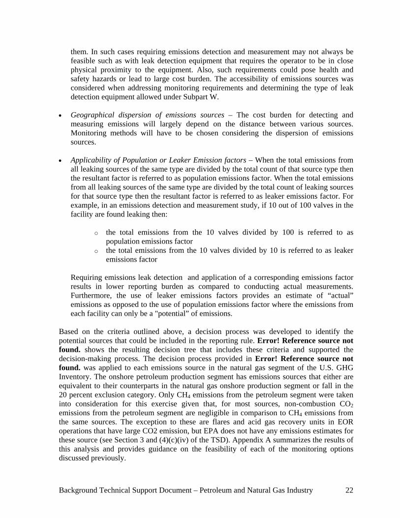


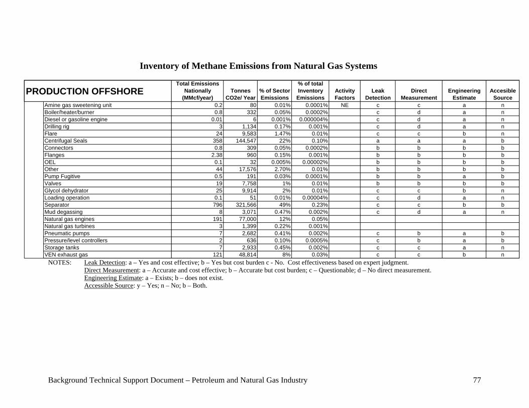


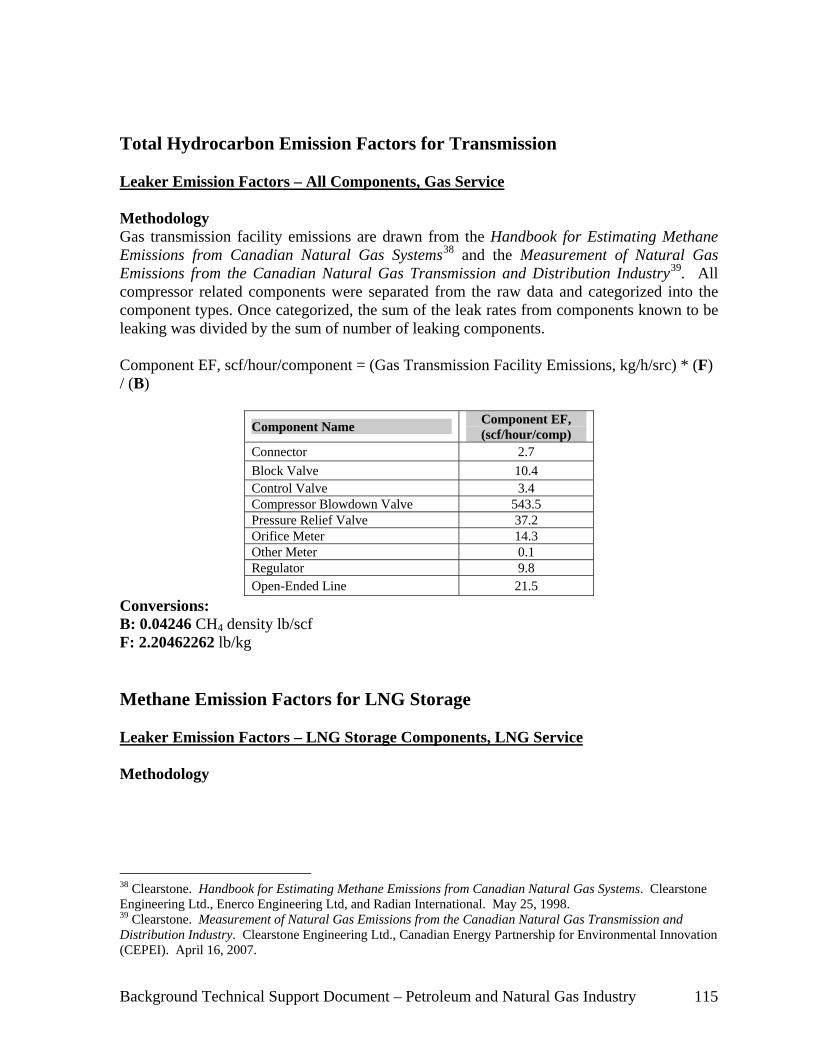


![Greenhouse Gas Emissions and Emissions Trading in North … · 2020. 2. 23. · 2002] Stephenson-Greenhouse Gas Emissions, Kyoto and U.S. Response 45 greenhouse gas molecules. This](https://static.fdocuments.in/doc/165x107/60facf56e286b02f9b10de99/greenhouse-gas-emissions-and-emissions-trading-in-north-2020-2-23-2002-stephenson-greenhouse.jpg)