Grease Jockey Chassis Lubrication System · Grease Jockey® Chassis Lubrication System 312054M EN...
26
Instructions – Parts Grease Jockey ® Chassis Lubrication System 312054M EN For on-board, automatic lubrication of trucks and heavy-use vehicles. For professional use only. Maximum Working Pressure: See Technical Data, page 23 Important Safety Instructions Read all warnings and instructions in this manual. Save these instructions. Bulletin GJ-30050
Transcript of Grease Jockey Chassis Lubrication System · Grease Jockey® Chassis Lubrication System 312054M EN...
Instructions – Parts
Grease Jockey® Chassis
Lubrication System 312054MEN
For on-board, automatic lubrication of trucks and heavy-use vehicles. For professional use only.
Maximum Working Pressure: See Technical Data, page 23
Important Safety InstructionsRead all warnings and instructions in this manual. Save these instructions.
Bulletin GJ-30050
Warnings
2 312054M
WarningsThe following warnings are for the setup, use, grounding, maintenance, and repair of this equipment. The exclama-tion point symbol alerts you to a general warning and the hazard symbol refers to procedure-specific risk. Refer back to these warnings. Additional, product-specific warnings may be found throughout the body of this manual where applicable.
WARNINGFIRE AND EXPLOSION HAZARD When flammable fluids are present in the work area, such as gasoline and windshield wiper fluid, be aware that flammable fumes can ignite or explode. To help prevent fire and explosion:• Use equipment only in well ventilated area.• Eliminate all ignition sources, such as cigarettes and portable electric lamps. • Keep work area free of debris, including rags and spilled or open containers of solvent and gasoline.• Do not plug or unplug power cords or turn lights on or off when flammable fumes are present.• Ground all equipment in the work area.• Use only grounded hoses.• If there is static sparking or you feel a shock, stop operation immediately. Do not use equipment
until you identify and correct the problem.• Keep a working fire extinguisher in the work area.
EQUIPMENT MISUSE HAZARD Misuse can cause death or serious injury.• Do not operate the unit when fatigued or under the influence of drugs or alcohol.• Do not exceed the maximum working pressure or temperature rating of the lowest rated system
component. See Technical Data in all equipment manuals.• Use fluids and solvents that are compatible with equipment wetted parts. See Technical Data in all
equipment manuals. Read fluid and solvent manufacturer’s warnings. For complete information about your material, request MSDS forms from distributor or retailer.
• Check equipment daily. Repair or replace worn or damaged parts immediately with genuine manu-facturer’s replacement parts only.
• Do not alter or modify equipment.• Use equipment only for its intended purpose. Call your distributor for information.• Route hoses and cables away from traffic areas, sharp edges, moving parts, and hot surfaces.• Do not kink or over bend hoses or use hoses to pull equipment.• Keep children and animals away from work area.• Comply with all applicable safety regulations.
ELECTRIC SHOCK HAZARDImproper grounding, setup, or usage of the system can cause electric shock.• Turn off and disconnect power at main switch before disconnecting any cables and before servicing
equipment.• Connect only to grounded power source.• All electrical wiring must be done by a qualified electrician and comply with all local codes and
regulations.
Warnings
312054M 3
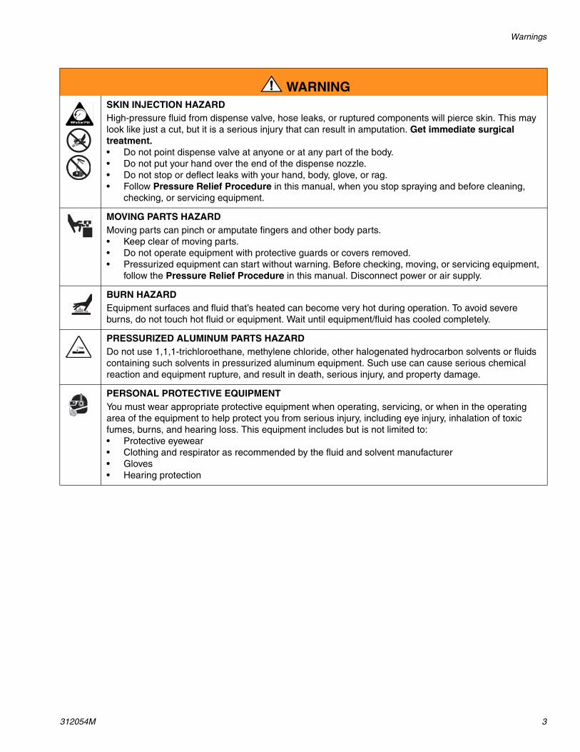
SKIN INJECTION HAZARDHigh-pressure fluid from dispense valve, hose leaks, or ruptured components will pierce skin. This may look like just a cut, but it is a serious injury that can result in amputation. Get immediate surgical treatment.• Do not point dispense valve at anyone or at any part of the body.• Do not put your hand over the end of the dispense nozzle.• Do not stop or deflect leaks with your hand, body, glove, or rag.• Follow Pressure Relief Procedure in this manual, when you stop spraying and before cleaning,
checking, or servicing equipment.
MOVING PARTS HAZARD Moving parts can pinch or amputate fingers and other body parts.• Keep clear of moving parts.• Do not operate equipment with protective guards or covers removed.• Pressurized equipment can start without warning. Before checking, moving, or servicing equipment,
follow the Pressure Relief Procedure in this manual. Disconnect power or air supply.
BURN HAZARDEquipment surfaces and fluid that’s heated can become very hot during operation. To avoid severe burns, do not touch hot fluid or equipment. Wait until equipment/fluid has cooled completely.
PRESSURIZED ALUMINUM PARTS HAZARD Do not use 1,1,1-trichloroethane, methylene chloride, other halogenated hydrocarbon solvents or fluids containing such solvents in pressurized aluminum equipment. Such use can cause serious chemical reaction and equipment rupture, and result in death, serious injury, and property damage.
PERSONAL PROTECTIVE EQUIPMENTYou must wear appropriate protective equipment when operating, servicing, or when in the operating area of the equipment to help protect you from serious injury, including eye injury, inhalation of toxic fumes, burns, and hearing loss. This equipment includes but is not limited to:• Protective eyewear • Clothing and respirator as recommended by the fluid and solvent manufacturer• Gloves• Hearing protection
WARNING
Installation
4 312054M
InstallationFill all lube points with grease before removing zerk fit-tings to change to tube connector fittings. This ensures each lube point will readily accept grease.
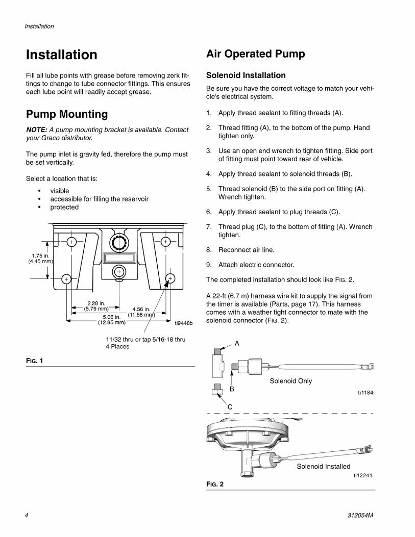
Pump MountingNOTE: A pump mounting bracket is available. Contact your Graco distributor.
The pump inlet is gravity fed, therefore the pump must be set vertically.
Select a location that is:
• visible • accessible for filling the reservoir• protected
Air Operated Pump
Solenoid Installation
Be sure you have the correct voltage to match your vehi-cle's electrical system.
1. Apply thread sealant to fitting threads (A).
2. Thread fitting (A), to the bottom of the pump. Hand tighten only.
3. Use an open end wrench to tighten fitting. Side port of fitting must point toward rear of vehicle.
4. Apply thread sealant to solenoid threads (B).
5. Thread solenoid (B) to the side port on fitting (A). Wrench tighten.
6. Apply thread sealant to plug threads (C).
7. Thread plug (C), to the bottom of fitting (A). Wrench tighten.
8. Reconnect air line.
9. Attach electric connector.
The completed installation should look like FIG. 2.
A 22-ft (6.7 m) harness wire kit to supply the signal from the timer is available (Parts, page 17). This harness comes with a weather tight connector to mate with the solenoid connector (FIG. 2).
FIG. 1
11/32 thru or tap 5/16-18 thru4 Places
FIG. 2
Solenoid Only
Solenoid Installed
B
A
C
Installation
312054M 5
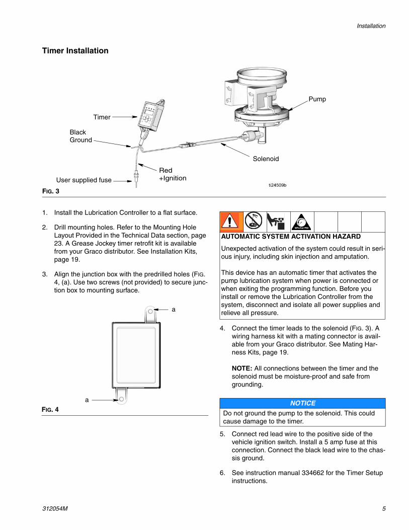
Timer Installation
1. Install the Lubrication Controller to a flat surface.
2. Drill mounting holes. Refer to the Mounting Hole Layout Provided in the Technical Data section, page 23. A Grease Jockey timer retrofit kit is available from your Graco distributor. See Installation Kits, page 19.
3. Align the junction box with the predrilled holes (FIG. 4, (a). Use two screws (not provided) to secure junc-tion box to mounting surface.
4. Connect the timer leads to the solenoid (FIG. 3). A wiring harness kit with a mating connector is avail-able from your Graco distributor. See Mating Har-ness Kits, page 19.
NOTE: All connections between the timer and the solenoid must be moisture-proof and safe from grounding.
5. Connect red lead wire to the positive side of the vehicle ignition switch. Install a 5 amp fuse at this connection. Connect the black lead wire to the chas-sis ground.
6. See instruction manual 334662 for the Timer Setup instructions.
FIG. 3
Pump
Solenoid
Timer
Red +Ignition
BlackGround
User supplied fuse
FIG. 4
a
a
AUTOMATIC SYSTEM ACTIVATION HAZARD
Unexpected activation of the system could result in seri-ous injury, including skin injection and amputation.
This device has an automatic timer that activates the pump lubrication system when power is connected or when exiting the programming function. Before you install or remove the Lubrication Controller from the system, disconnect and isolate all power supplies and relieve all pressure.
NOTICEDo not ground the pump to the solenoid. This could cause damage to the timer.
Installation
6 312054M
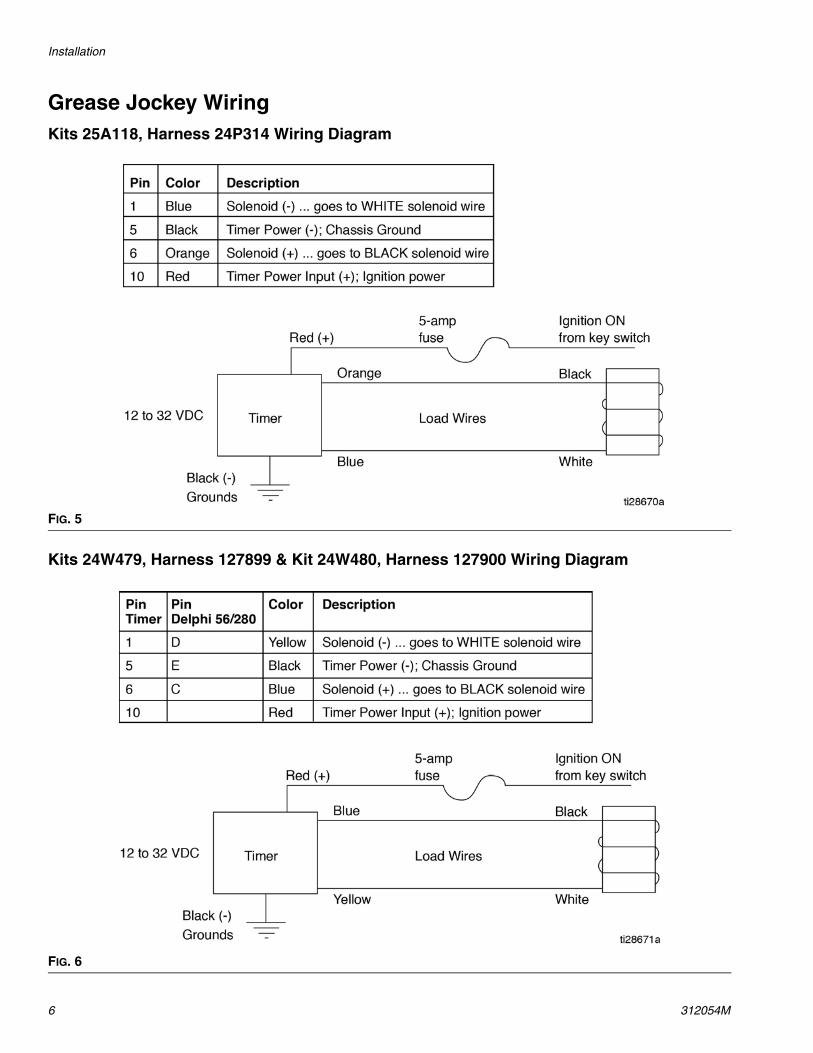
Grease Jockey WiringKits 25A118, Harness 24P314 Wiring Diagram
Kits 24W479, Harness 127899 & Kit 24W480, Harness 127900 Wiring Diagram
FIG. 5
FIG. 6
Installation
312054M 7
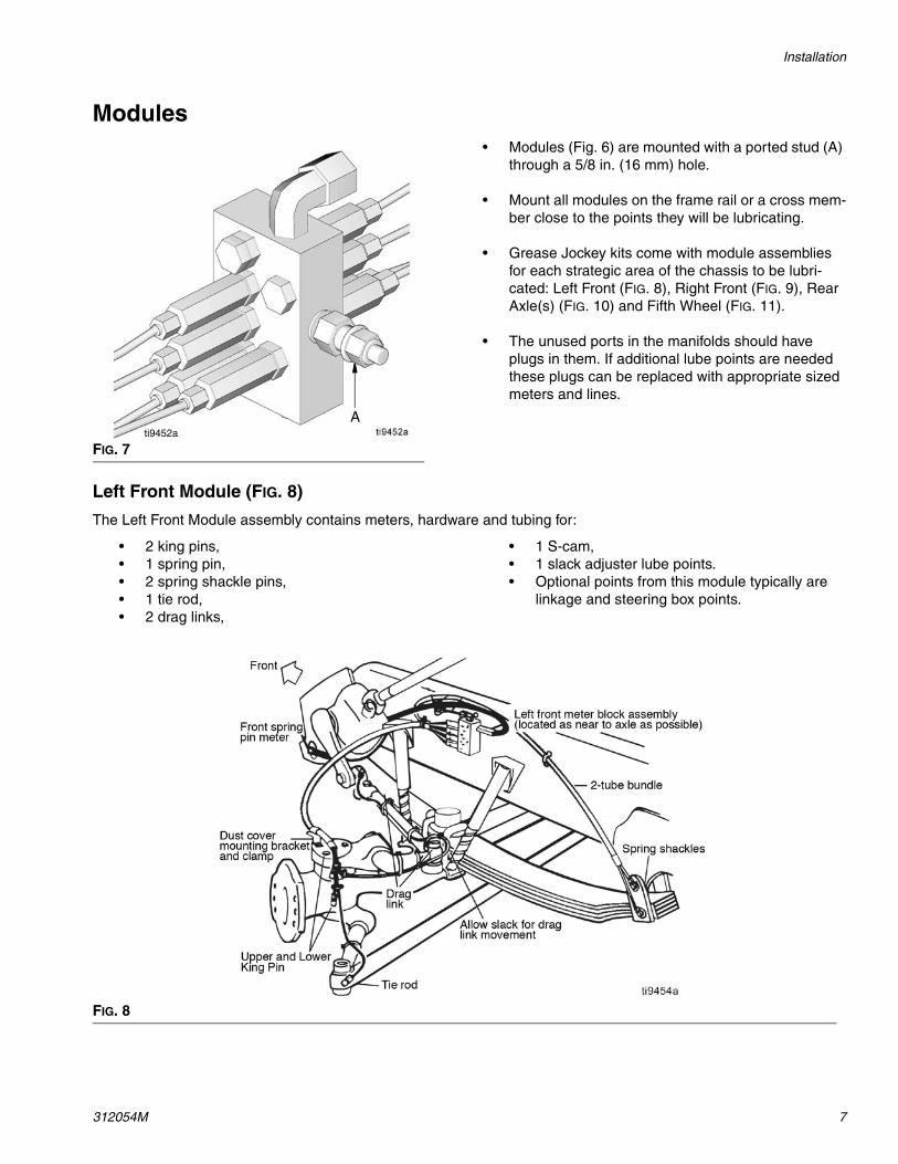
Modules• Modules (Fig. 6) are mounted with a ported stud (A)
through a 5/8 in. (16 mm) hole.
• Mount all modules on the frame rail or a cross mem-ber close to the points they will be lubricating.
• Grease Jockey kits come with module assemblies for each strategic area of the chassis to be lubri-cated: Left Front (FIG. 8), Right Front (FIG. 9), Rear Axle(s) (FIG. 10) and Fifth Wheel (FIG. 11).
• The unused ports in the manifolds should have plugs in them. If additional lube points are needed these plugs can be replaced with appropriate sized meters and lines.
Left Front Module (FIG. 8)
The Left Front Module assembly contains meters, hardware and tubing for:
• 2 king pins, • 1 spring pin,• 2 spring shackle pins, • 1 tie rod, • 2 drag links,
• 1 S-cam, • 1 slack adjuster lube points. • Optional points from this module typically are
linkage and steering box points.
FIG. 7ti9452a
A
FIG. 8 tti9454
Installation
8 312054M
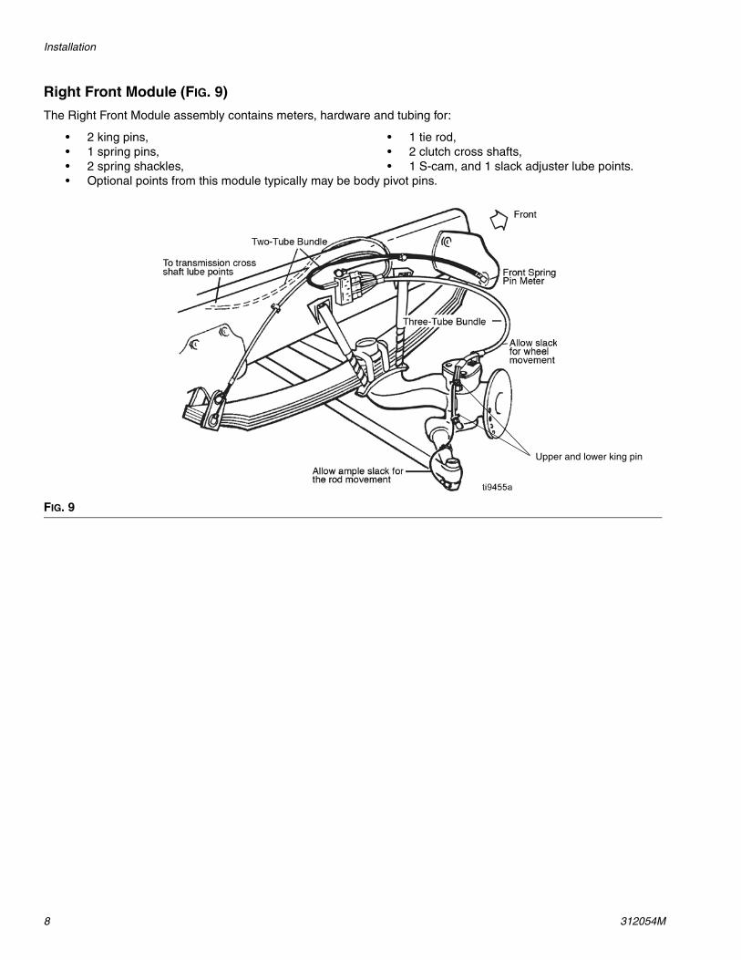
Right Front Module (FIG. 9)
The Right Front Module assembly contains meters, hardware and tubing for:
• 2 king pins, • 1 spring pins, • 2 spring shackles,
• 1 tie rod, • 2 clutch cross shafts, • 1 S-cam, and 1 slack adjuster lube points.
• Optional points from this module typically may be body pivot pins.
FIG. 9
Upper and lower king pin
Installation
312054M 9
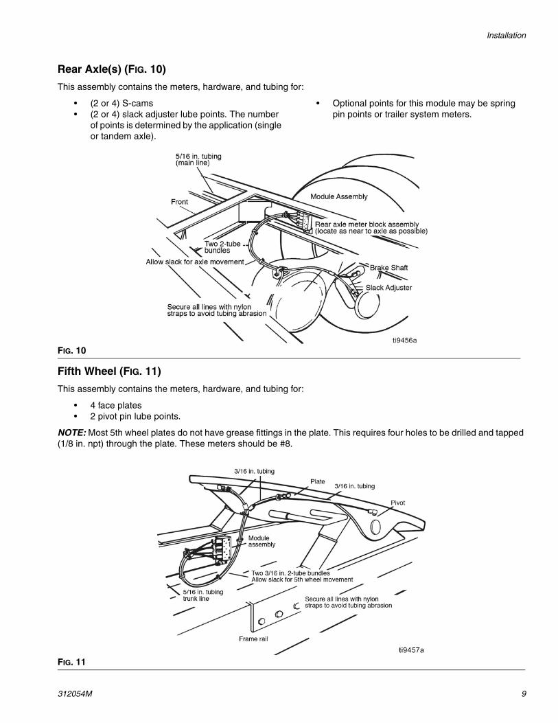
Rear Axle(s) (FIG. 10)
This assembly contains the meters, hardware, and tubing for:
• (2 or 4) S-cams • (2 or 4) slack adjuster lube points. The number
of points is determined by the application (single or tandem axle).
• Optional points for this module may be spring pin points or trailer system meters.
Fifth Wheel (FIG. 11)
This assembly contains the meters, hardware, and tubing for:
• 4 face plates • 2 pivot pin lube points.
NOTE: Most 5th wheel plates do not have grease fittings in the plate. This requires four holes to be drilled and tapped (1/8 in. npt) through the plate. These meters should be #8.
FIG. 10
FIG. 11
Installation
10 312054M
Tubing
Preparation
1. Measure approximate lengths of tube bundles, leav-ing extra length for trimming at the lube points.
2. Cut the outside sheath on tube bundles back to the point where this bundle meets it’s first lube point. Be careful not to puncture or cut the tubes inside. Use a stripper to help prevent damage to the tubes.
3. Peel back the outside sheath onto itself to create a collar and cut off the excess. Be careful not to sever the remaining sheath or tubes.
4. Align tubing with fitting. Make cuts square and clean with an anvil type cutter.
5. Allow ample slack for tube movement and ease of installation.
Installation
A self aligned ferrule is supplied with all 3/16 in. and 5/16 in. fittings. It is not necessary to remove the nut and ferrule to seat the tube into the fitting.
1. Make sure the tube is well seated into each fitting. Brass inserts are supplied with kits for use with 5/16 in. tubing. These inserts must be used at every 5/16 in. connection.
2. Route the 5/16 in. main line tube from the pump to the manifolds.
NOTE: The 5/16 in. main line tube may also be used as the air supply line to the solenoid. It should be routed inside the frame for protection and well secured.
Filling System and Start Up
Rigid Reservoir Fill and Refill
1. Fill reservoir through fill stud. Pump output port should be connected to system or plugged to avoid spillage.
2. Fill reservoir to full line. Do not overfill.
Reducing Grease in Reservoir When Overfilled
Follow this procedure to reduce the grease in the reser-voir if the pump is accidentally overfilled.
1. Disconnect the main line from the pump or at the first module.
NOTICE• When installing the tubing avoid routing it close to a
heat source such as an exhaust manifold, muffler, turbocharger, etc.
• Non-approved nylon or air brake tubing should not be used.
• Always use approved 3/16 in. (5 mm) and 5/16 in. (8 mm) OD tubing.
The 3/16 in. (5 mm) tubing comes in three configu-rations.
• Single tubes: black or orange,
• 2 tube bundles: black with an orange tube inside sheath.
• 3 tube bundle: black, blue and orange tube inside a sheath.
- The orange tube is connected to the highest output meter.
- The blue tube is connected to a lesser or equal output meter.
- The black tube is connected to the lowest or equal output meter of the bundle group.
NOTICE• The Grease Jockey system is designed to pump
lightweight fluid greases and oil over a wide range of conditions.
• Choose a lubricant compatible with the system’s operating temperature.
• Use lubricant part number 557941, or a quality NLGI “0” or “00” lithium base grease with an “EP” additive.
• Systems using fluid grease:
- MUST use NGLI grade “00” grease at tempera-tures below 50°F (10 °C).
- MAY use NGLI grade “0” or “0” at temperatures above 50°F (10 °C).
Installation
312054M 11
2. Cycle pump with the timer on “test” for a few min-utes until the level of grease is acceptable. Be sure to capture grease.
3. In rigid reservoir, clean breather tube of residual grease.
4. Return timer to original setting and reconnect main line.
Pump Filter
The pump assembly contains a filter to remove impuri-ties and dirt that may be present in the lubricant used to fill the reservoir.
Clean filter after every four or five reservoir refills. To clean the filter:
1. Remove the quick fill fluid fitting.
2. Remove the filter and clean with solvent or com-pressed air as appropriate.
3. Replace filter in pump body, flanged end facing out.
4. Reassemble the quick fill fluid fitting.
A mating female quick disconnect is available. Contact your Graco distributor. Order part number 557877.
Installation
12 312054M
Adjusting Grease Output Volume
If a meter is not producing the correct amount of lubri-cant for a specific location on a vehicle or if a replace-ment meter of correct size is not available, output spacer washers can be installed to adjust the meter’s output volume.
Use Table 1 to determine which size meter is appropri-ate for the grease location.
To change output volume:
1. Relieve pressure, page 13.
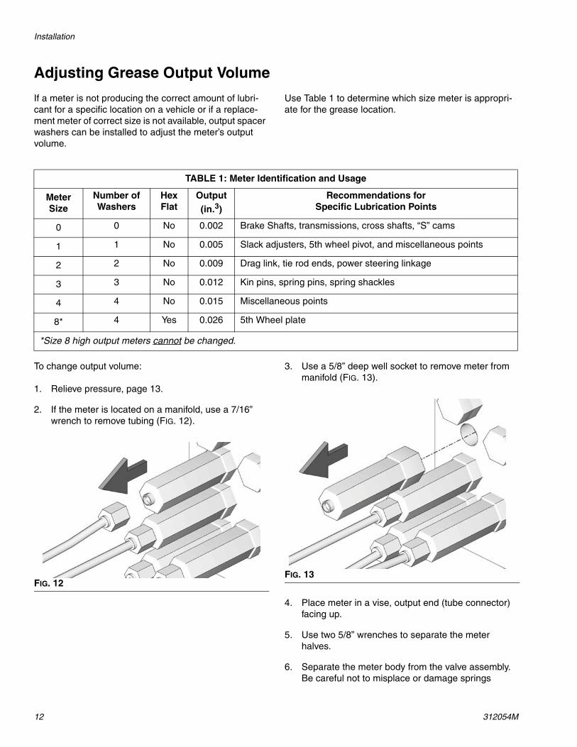
2. If the meter is located on a manifold, use a 7/16” wrench to remove tubing (FIG. 12).
3. Use a 5/8” deep well socket to remove meter from manifold (FIG. 13).
4. Place meter in a vise, output end (tube connector) facing up.
5. Use two 5/8” wrenches to separate the meter halves.
6. Separate the meter body from the valve assembly. Be careful not to misplace or damage springs
TABLE 1: Meter Identification and Usage
Meter Size
Number of Washers
Hex Flat
Output (in.3)
Recommendations for Specific Lubrication Points
0 0 No 0.002 Brake Shafts, transmissions, cross shafts, “S” cams
1 1 No 0.005 Slack adjusters, 5th wheel pivot, and miscellaneous points
2 2 No 0.009 Drag link, tie rod ends, power steering linkage
3 3 No 0.012 Kin pins, spring pins, spring shackles
4 4 No 0.015 Miscellaneous points
8* 4 Yes 0.026 5th Wheel plate
*Size 8 high output meters cannot be changed.
FIG. 12FIG. 13
Installation
312054M 13
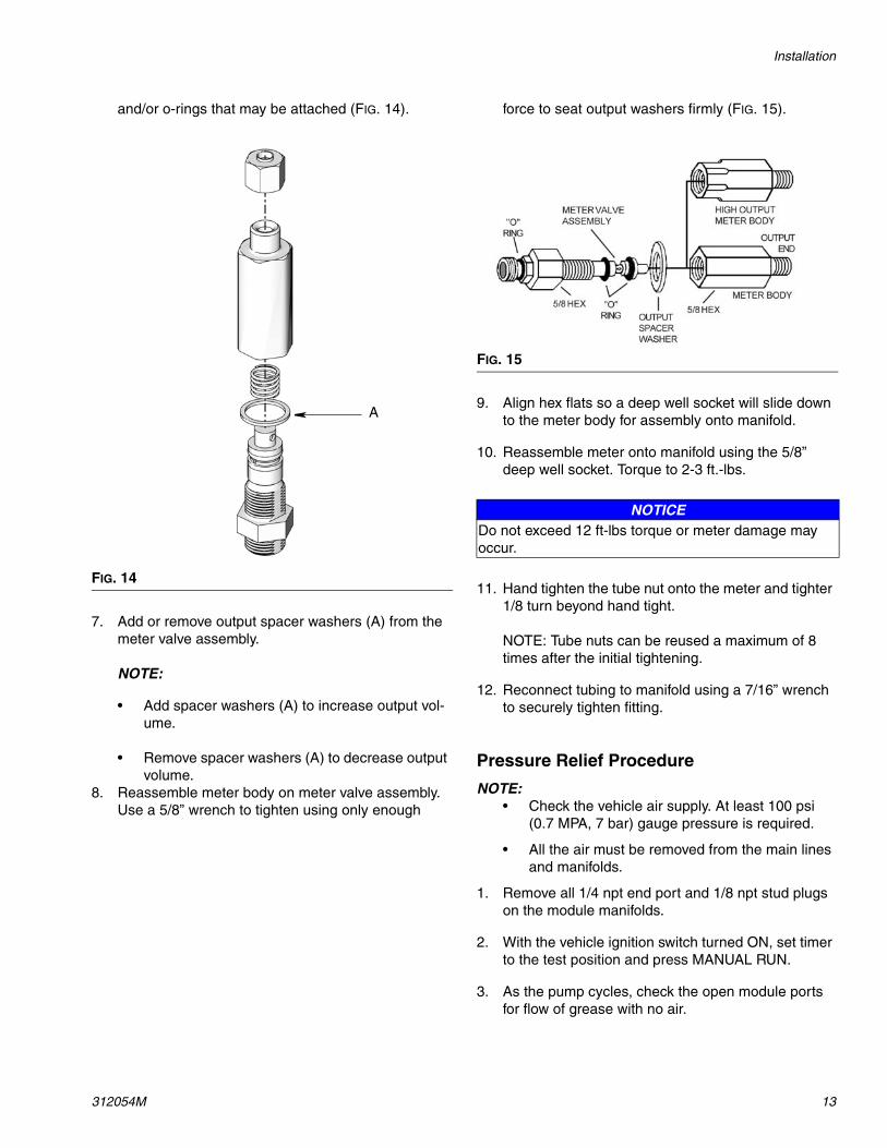
and/or o-rings that may be attached (FIG. 14).
7. Add or remove output spacer washers (A) from the meter valve assembly.
NOTE:
• Add spacer washers (A) to increase output vol-ume.
• Remove spacer washers (A) to decrease output volume.
8. Reassemble meter body on meter valve assembly. Use a 5/8” wrench to tighten using only enough
force to seat output washers firmly (FIG. 15).
9. Align hex flats so a deep well socket will slide down to the meter body for assembly onto manifold.
10. Reassemble meter onto manifold using the 5/8” deep well socket. Torque to 2-3 ft.-lbs.
11. Hand tighten the tube nut onto the meter and tighter 1/8 turn beyond hand tight.
NOTE: Tube nuts can be reused a maximum of 8 times after the initial tightening.
12. Reconnect tubing to manifold using a 7/16” wrench to securely tighten fitting.
Pressure Relief Procedure
NOTE: • Check the vehicle air supply. At least 100 psi
(0.7 MPA, 7 bar) gauge pressure is required.
• All the air must be removed from the main lines and manifolds.
1. Remove all 1/4 npt end port and 1/8 npt stud plugs on the module manifolds.
2. With the vehicle ignition switch turned ON, set timer to the test position and press MANUAL RUN.
3. As the pump cycles, check the open module ports for flow of grease with no air.
FIG. 14
A
FIG. 15
NOTICEDo not exceed 12 ft-lbs torque or meter damage may occur.
Installation
14 312054M
4. Check the open port closest to the pump first, pro-ceeding to the port furthermost from the pump last. This will push out the air in the main line(s).
5. When the flow of grease from a port is free of air, close the port and continue this process until all ports have been checked.
NOTE: The 3/16 in. (5 mm) distribution lines are pre-filled. They should not require purging of air.
6. Let the system run in the test position for a few min-utes. Check all line connections to be sure they are holding pressure. Check at lube points to be sure lubricant is moving to this point in the system.
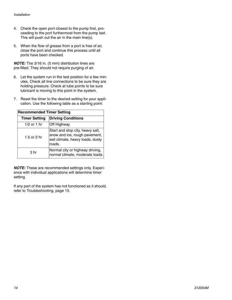
7. Reset the timer to the desired setting for your appli-cation. Use the following table as a starting point:
NOTE: These are recommended settings only. Experi-ence with individual applications will determine timer setting.
If any part of the system has not functioned as it should, refer to Troubleshooting, page 15.
Recommended Timer Setting
Timer Setting Driving Conditions
1/2 or 1 hr Off Highway
1.5 or 2 hr
Start and stop city, heavy salt, snow and ice, rough pavement, wet climate, heavy loads, dusty roads.
3 hrNormal city or highway driving, normal climate, moderate loads.
Troubleshooting
312054M 15
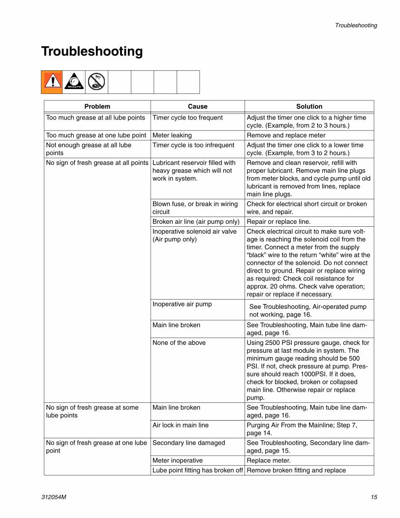
Troubleshooting
Problem Cause Solution
Too much grease at all lube points Timer cycle too frequent Adjust the timer one click to a higher time cycle. (Example, from 2 to 3 hours.)
Too much grease at one lube point Meter leaking Remove and replace meter
Not enough grease at all lube points
Timer cycle is too infrequent Adjust the timer one click to a lower time cycle. (Example, from 3 to 2 hours.)
No sign of fresh grease at all points Lubricant reservoir filled with heavy grease which will not work in system.
Remove and clean reservoir, refill with proper lubricant. Remove main line plugs from meter blocks, and cycle pump until old lubricant is removed from lines, replace main line plugs.
Blown fuse, or break in wiring circuit
Check for electrical short circuit or broken wire, and repair.
Broken air line (air pump only) Repair or replace line.
Inoperative solenoid air valve (Air pump only)
Check electrical circuit to make sure volt-age is reaching the solenoid coil from the timer. Connect a meter from the supply “black” wire to the return “white” wire at the connector of the solenoid. Do not connect direct to ground. Repair or replace wiring as required: Check coil resistance for approx. 20 ohms. Check valve operation; repair or replace if necessary.
Inoperative air pump See Troubleshooting, Air-operated pump not working, page 16.
Main line broken See Troubleshooting, Main tube line dam-aged, page 16.
None of the above Using 2500 PSI pressure gauge, check for pressure at last module in system. The minimum gauge reading should be 500 PSI. If not, check pressure at pump. Pres-sure should reach 1000PSI. If it does, check for blocked, broken or collapsed main line. Otherwise repair or replace pump.
No sign of fresh grease at some lube points
Main line broken See Troubleshooting, Main tube line dam-aged, page 16.
Air lock in main line Purging Air From the Mainline; Step 7, page 14.
No sign of fresh grease at one lube point
Secondary line damaged See Troubleshooting, Secondary line dam-aged, page 15.
Meter inoperative Replace meter.
Lube point fitting has broken off Remove broken fitting and replace
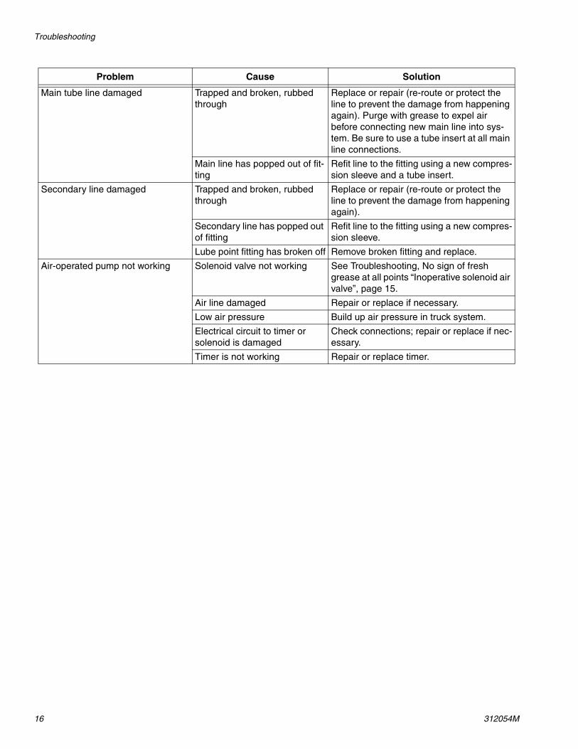
Troubleshooting
16 312054M
Main tube line damaged Trapped and broken, rubbed through
Replace or repair (re-route or protect the line to prevent the damage from happening again). Purge with grease to expel air before connecting new main line into sys-tem. Be sure to use a tube insert at all main line connections.
Main line has popped out of fit-ting
Refit line to the fitting using a new compres-sion sleeve and a tube insert.
Secondary line damaged Trapped and broken, rubbed through
Replace or repair (re-route or protect the line to prevent the damage from happening again).
Secondary line has popped out of fitting
Refit line to the fitting using a new compres-sion sleeve.
Lube point fitting has broken off Remove broken fitting and replace.
Air-operated pump not working Solenoid valve not working See Troubleshooting, No sign of fresh grease at all points “Inoperative solenoid air valve”, page 15.
Air line damaged Repair or replace if necessary.
Low air pressure Build up air pressure in truck system.
Electrical circuit to timer or solenoid is damaged
Check connections; repair or replace if nec-essary.
Timer is not working Repair or replace timer.
Problem Cause Solution
Rebuilding Grease Jockey Pump
312054M 17
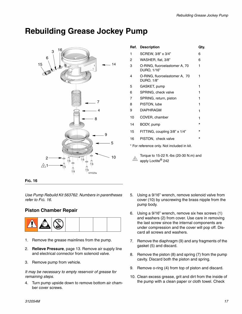
Rebuilding Grease Jockey Pump
Use Pump Rebuild Kit 563762. Numbers in parentheses refer to FIG. 16.
Piston Chamber Repair
1. Remove the grease mainlines from the pump.
2. Relieve Pressure, page 13. Remove air supply line and electrical connector from solenoid valve.
3. Remove pump from vehicle.
It may be necessary to empty reservoir of grease for remaining steps.
4. Turn pump upside down to remove bottom air cham-ber cover screws.
5. Using a 9/16” wrench, remove solenoid valve from cover (10) by unscrewing the brass nipple from the pump body.
6. Using a 9/16” wrench, remove six hex screws (1) and washers (2) from cover. Use care in removing the last screw since the internal components are under compression and the cover will pop off. Dis-card all screws and washers.
7. Remove the diaphragm (9) and any fragments of the gasket (5) and discard.
8. Remove the piston (8) and spring (7) from the pump cavity. Discard both the piston and spring.
9. Remove o-ring (4) from top of piston and discard.
10. Clean excess grease, grit and dirt from the inside of the pump with a clean paper or cloth towel. Check
FIG. 16
6
7
8
9
102
1
5
3
1
14
16
15
4
Ref. Description Qty.
1 SCREW, 3/8” x 3/4” 6
2 WASHER, flat, 3/8” 6
3 O-RING, fluoroelastomer A, 70 DURO, 1/16”
1
4 O-RING, fluoroelastomer A, 70 DURO, 1/8”
1
5 GASKET, pump 1
6 SPRING, check valve 1
7 SPRING, return, piston 1
8 PISTON, lube 1
9 DIAPHRAGM 1
10 COVER, chamber 1
14 BODY, pump *15 FITTING, coupling 3/8” x 1/4” *16 PISTON, check valve ** For reference only. Not included in kit.
Torque to 15-22 ft.-lbs (20-30 N.m) and
apply Loctite® 2421
Rebuilding Grease Jockey Pump
18 312054M
piston cavity for scoring or scrapes. Clean piston. Make sure there are no fibers from cloth left behind.
11. Check to make sure flapper valve is visible and loose in top of piston cavity. If flapper is not visible or frozen in place, the pump cannot be repaired. Replacement part number is 563625.
12. Assemble new o-ring and new spring to the new pis-ton and insert in pump. To aid in reinsertion, apply a small amount of grease to the o-ring.
13. Position new diaphragm on piston. Make sure orien-tation is according to FIG. 16.
14. Position new gasket and cap back onto pump and screw into place. Replace o-ring and hex screws. Torque to 15-22 ft.-lbs. Alternate tightening screws around cover to avoid excessive tilting of cover.
Check Valve Repair
1. Using a 3/4” wrench, remove fill stud fitting (15) from pump body.
2. Using a 5/16” wrench, remove check valve spring (6), o-ring (3) and check valve piston (16). Discard spring and o-ring.
3. Clean cavity with clean paper or cloth towel. Make sure no fibers are left in the cavity.
4. Replace o-ring (3) and reinstall check valve piston in cavity. Make sure piston is properly oriented in cav-ity -- o-ring on the outside end.
5. Install new check valve spring (6) in cavity.
6. Apply pipe dope to fitting (15) and reinstall.
Assembling Pump Onto Vehicle
1. Assemble pump onto vehicle.
2. Connect solenoid air supply line to the side port of the solenoid.
3. Reconnect solenoid electrical harness.
4. If reservoir was emptied, refill with appropriate grease.
5. After vehicle air pressures has reached a minimum of 100 psi (6.89 bar, 0.689 MPa):
• turn ignition to ON• Timer to TEST position• push the MANUAL RUN button
Watch the pump outlet for grease flow.
6. Once grease flows from the outlet:
• stop the cycling• return the timer to the original setting• reconnect the mainline to the pump
NOTE: Any tube nut can be removed and reconnected up to 8 times. to reattach, hand tighten up to original make-up position plus 1/16 turn to seat ferrule.
7. Pump can now be returned to service.
Kits
312054M 19
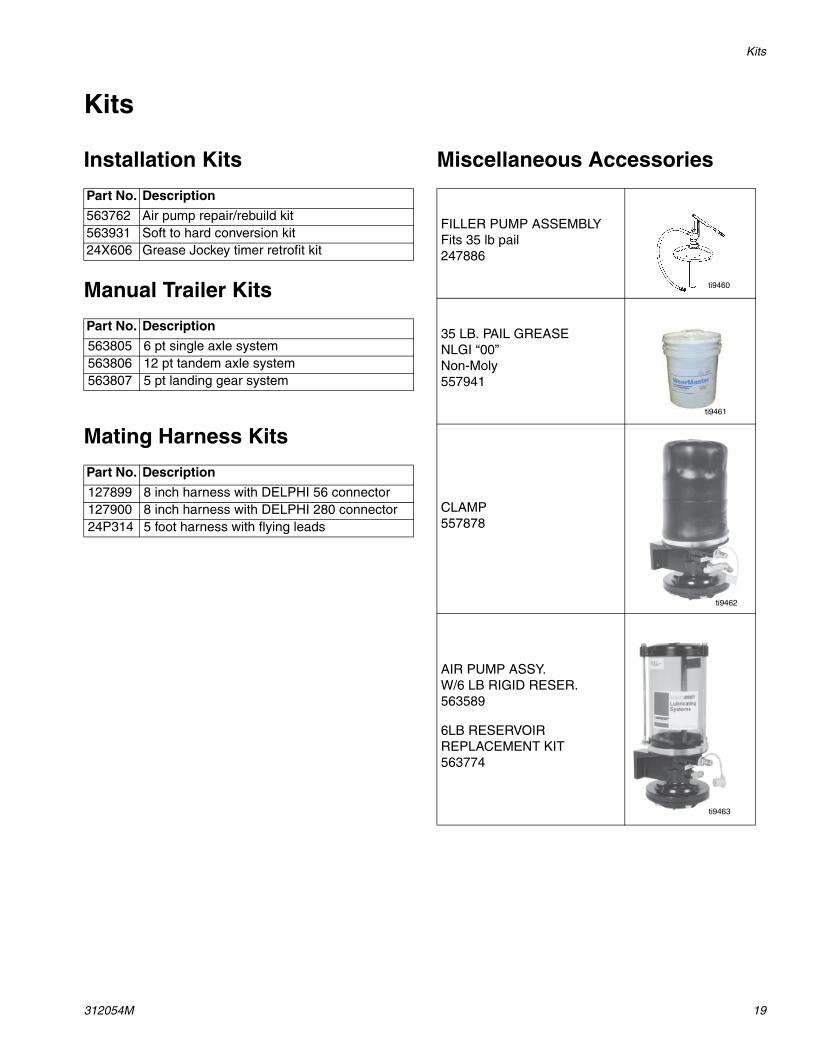
Kits
Installation Kits
Manual Trailer Kits
Mating Harness Kits
Miscellaneous Accessories
Part No. Description
563762 Air pump repair/rebuild kit563931 Soft to hard conversion kit24X606 Grease Jockey timer retrofit kit
Part No. Description
563805 6 pt single axle system563806 12 pt tandem axle system563807 5 pt landing gear system
Part No. Description
127899 8 inch harness with DELPHI 56 connector127900 8 inch harness with DELPHI 280 connector24P314 5 foot harness with flying leads
FILLER PUMP ASSEMBLYFits 35 lb pail247886
35 LB. PAIL GREASENLGI “00”Non-Moly557941
CLAMP557878
AIR PUMP ASSY.W/6 LB RIGID RESER.563589
6LB RESERVOIR REPLACEMENT KIT563774
ti9460
ti9461
ti9462
ti9463
Kits
20 312054M
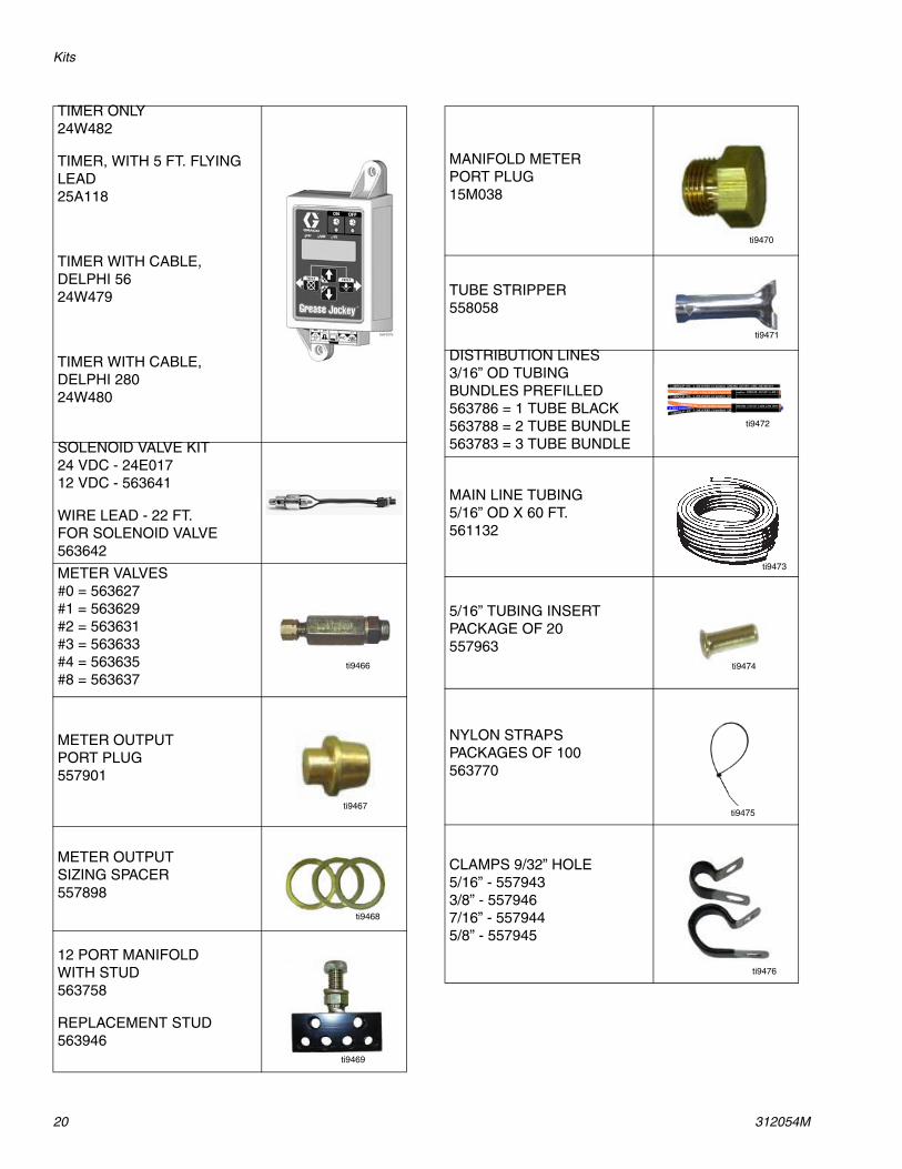
TIMER ONLY24W482
TIMER, WITH 5 FT. FLYING LEAD25A118
TIMER WITH CABLE, DELPHI 56 24W479
TIMER WITH CABLE, DELPHI 28024W480
SOLENOID VALVE KIT24 VDC - 24E01712 VDC - 563641
WIRE LEAD - 22 FT.FOR SOLENOID VALVE563642
METER VALVES#0 = 563627#1 = 563629#2 = 563631#3 = 563633#4 = 563635#8 = 563637
METER OUTPUTPORT PLUG557901
METER OUTPUTSIZING SPACER557898
12 PORT MANIFOLDWITH STUD563758
REPLACEMENT STUD563946
ti9466
ti9467
ti9468
ti9469
MANIFOLD METERPORT PLUG15M038
TUBE STRIPPER558058
DISTRIBUTION LINES3/16” OD TUBINGBUNDLES PREFILLED563786 = 1 TUBE BLACK563788 = 2 TUBE BUNDLE563783 = 3 TUBE BUNDLE
MAIN LINE TUBING5/16” OD X 60 FT.561132
5/16” TUBING INSERTPACKAGE OF 20557963
NYLON STRAPSPACKAGES OF 100563770
CLAMPS 9/32” HOLE5/16” - 5579433/8” - 5579467/16” - 5579445/8” - 557945
ti9470
ti9471
ti9472
ti9473
ti9474
ti9475
ti9476
Kits
312054M 21
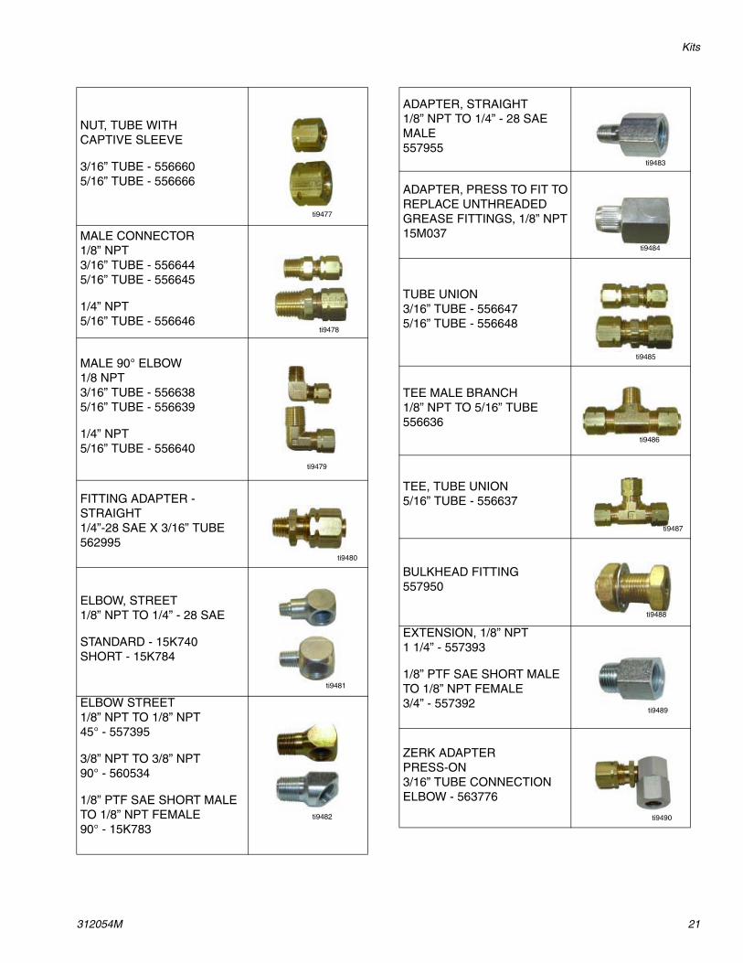
NUT, TUBE WITHCAPTIVE SLEEVE
3/16” TUBE - 5566605/16” TUBE - 556666
MALE CONNECTOR 1/8” NPT3/16” TUBE - 5566445/16” TUBE - 556645
1/4” NPT5/16” TUBE - 556646
MALE 90° ELBOW1/8 NPT3/16” TUBE - 5566385/16” TUBE - 556639
1/4” NPT5/16” TUBE - 556640
FITTING ADAPTER -STRAIGHT1/4”-28 SAE X 3/16” TUBE562995
ELBOW, STREET1/8” NPT TO 1/4” - 28 SAE
STANDARD - 15K740SHORT - 15K784
ELBOW STREET1/8” NPT TO 1/8” NPT45° - 557395
3/8” NPT TO 3/8” NPT90° - 560534
1/8” PTF SAE SHORT MALE TO 1/8” NPT FEMALE90° - 15K783
ti9477
ti9478
ti9479
ti9480
ti9481
ti9482
ADAPTER, STRAIGHT1/8” NPT TO 1/4” - 28 SAEMALE557955
ADAPTER, PRESS TO FIT TO REPLACE UNTHREADED GREASE FITTINGS, 1/8” NPT15M037
TUBE UNION3/16” TUBE - 5566475/16” TUBE - 556648
TEE MALE BRANCH1/8” NPT TO 5/16” TUBE556636
TEE, TUBE UNION5/16” TUBE - 556637
BULKHEAD FITTING557950
EXTENSION, 1/8” NPT1 1/4” - 557393
1/8” PTF SAE SHORT MALE TO 1/8” NPT FEMALE3/4” - 557392
ZERK ADAPTERPRESS-ON3/16” TUBE CONNECTIONELBOW - 563776
ti9483
ti9484
ti9485
ti9486
ti9487
ti9488
ti9489
ti9490
Kits
22 312054M
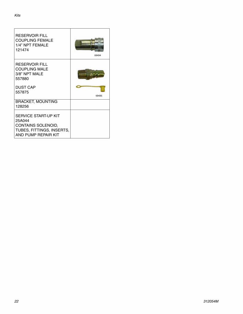
RESERVOIR FILLCOUPLING FEMALE1/4” NPT FEMALE121474
RESERVOIR FILLCOUPLING MALE3/8” NPT MALE557880
DUST CAP557875
BRACKET, MOUNTING128256
SERVICE START-UP KIT25A044CONTAINS SOLENOID, TUBES, FITTINGS, INSERTS, AND PUMP REPAIR KIT
ti9494
ti9495
Technical Data
312054M 23
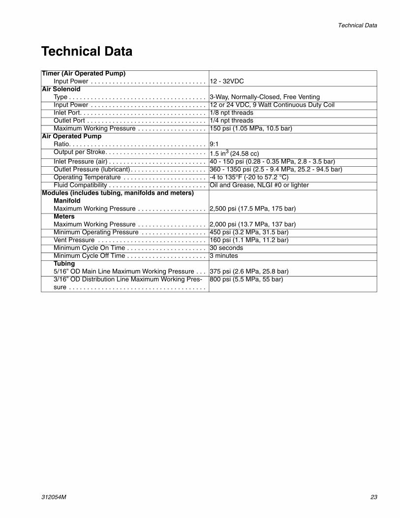
Technical Data
Timer (Air Operated Pump)Input Power . . . . . . . . . . . . . . . . . . . . . . . . . . . . . . . . 12 - 32VDC
Air SolenoidType . . . . . . . . . . . . . . . . . . . . . . . . . . . . . . . . . . . . . . 3-Way, Normally-Closed, Free VentingInput Power . . . . . . . . . . . . . . . . . . . . . . . . . . . . . . . . 12 or 24 VDC, 9 Watt Continuous Duty CoilInlet Port. . . . . . . . . . . . . . . . . . . . . . . . . . . . . . . . . . . 1/8 npt threadsOutlet Port . . . . . . . . . . . . . . . . . . . . . . . . . . . . . . . . . 1/4 npt threadsMaximum Working Pressure . . . . . . . . . . . . . . . . . . . 150 psi (1.05 MPa, 10.5 bar)
Air Operated PumpRatio. . . . . . . . . . . . . . . . . . . . . . . . . . . . . . . . . . . . . . 9:1Output per Stroke. . . . . . . . . . . . . . . . . . . . . . . . . . . . 1.5 in3 (24.58 cc)Inlet Pressure (air) . . . . . . . . . . . . . . . . . . . . . . . . . . . 40 - 150 psi (0.28 - 0.35 MPa, 2.8 - 3.5 bar)Outlet Pressure (lubricant) . . . . . . . . . . . . . . . . . . . . . 360 - 1350 psi (2.5 - 9.4 MPa, 25.2 - 94.5 bar)Operating Temperature . . . . . . . . . . . . . . . . . . . . . . . -4 to 135°F (-20 to 57.2 °C)Fluid Compatibility . . . . . . . . . . . . . . . . . . . . . . . . . . . Oil and Grease, NLGI #0 or lighter
Modules (includes tubing, manifolds and meters)ManifoldMaximum Working Pressure . . . . . . . . . . . . . . . . . . . 2,500 psi (17.5 MPa, 175 bar)MetersMaximum Working Pressure . . . . . . . . . . . . . . . . . . . 2,000 psi (13.7 MPa, 137 bar)Minimum Operating Pressure . . . . . . . . . . . . . . . . . . 450 psi (3.2 MPa, 31.5 bar)Vent Pressure . . . . . . . . . . . . . . . . . . . . . . . . . . . . . . 160 psi (1.1 MPa, 11.2 bar)Minimum Cycle On Time . . . . . . . . . . . . . . . . . . . . . . 30 secondsMinimum Cycle Off Time . . . . . . . . . . . . . . . . . . . . . . 3 minutesTubing5/16” OD Main Line Maximum Working Pressure . . . 375 psi (2.6 MPa, 25.8 bar)3/16” OD Distribution Line Maximum Working Pres-sure . . . . . . . . . . . . . . . . . . . . . . . . . . . . . . . . . . . . . .
800 psi (5.5 MPa, 55 bar)
Dimensions
24 312054M
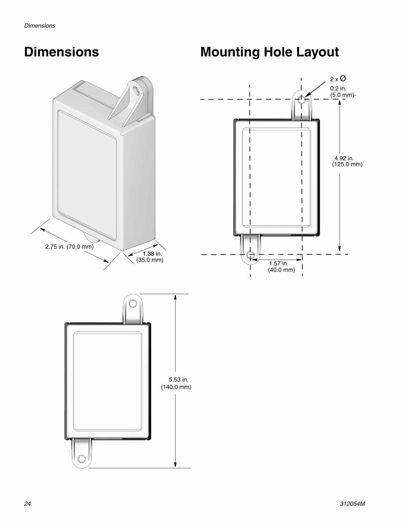
Dimensions Mounting Hole Layout
2.75 in. (70.0 mm)
5.53 in.(140.0 mm)
1.38 in.(35.0 mm)
1.57 in. (40.0 mm)
4.92 in.(125.0 mm)
2 x Ø0.2 in. (5.0 mm)-
Notes
312054M 25
Notes
All written and visual data contained in this document reflects the latest product information available at the time of publication. Graco reserves the right to make changes at any time without notice.
For patent information, see www.graco.com/patents.
Original instructions. This manual contains English. MM 312054
Graco Headquarters: MinneapolisInternational Offices: Belgium, China, Japan, Korea
GRACO INC. AND SUBSIDIARIES • P.O. BOX 1441 • MINNEAPOLIS MN 55440-1441 • USA
Copyright 2008, Graco Inc. All Graco manufacturing locations are registered to ISO 9001.www.graco.com
Revised March 2017
Graco Standard WarrantyGraco warrants all equipment referenced in this document which is manufactured by Graco and bearing its name to be free from defects in material and workmanship on the date of sale to the original purchaser for use. With the exception of any special, extended, or limited warranty published by Graco, Graco will, for a period of twelve months from the date of sale, repair or replace any part of the equipment determined by Graco to be defective. This warranty applies only when the equipment is installed, operated and maintained in accordance with Graco’s written recommendations.
This warranty does not cover, and Graco shall not be liable for general wear and tear, or any malfunction, damage or wear caused by faulty installation, misapplication, abrasion, corrosion, inadequate or improper maintenance, negligence, accident, tampering, or substitution of non-Graco component parts. Nor shall Graco be liable for malfunction, damage or wear caused by the incompatibility of Graco equipment with structures, accessories, equipment or materials not supplied by Graco, or the improper design, manufacture, installation, operation or maintenance of structures, accessories, equipment or materials not supplied by Graco.
This warranty is conditioned upon the prepaid return of the equipment claimed to be defective to an authorized Graco distributor for verification of the claimed defect. If the claimed defect is verified, Graco will repair or replace free of charge any defective parts. The equipment will be returned to the original purchaser transportation prepaid. If inspection of the equipment does not disclose any defect in material or workmanship, repairs will be made at a reasonable charge, which charges may include the costs of parts, labor, and transportation.
THIS WARRANTY IS EXCLUSIVE, AND IS IN LIEU OF ANY OTHER WARRANTIES, EXPRESS OR IMPLIED, INCLUDING BUT NOT LIMITED TO WARRANTY OF MERCHANTABILITY OR WARRANTY OF FITNESS FOR A PARTICULAR PURPOSE.
Graco’s sole obligation and buyer’s sole remedy for any breach of warranty shall be as set forth above. The buyer agrees that no other remedy (including, but not limited to, incidental or consequential damages for lost profits, lost sales, injury to person or property, or any other incidental or consequential loss) shall be available. Any action for breach of warranty must be brought within two (2) years of the date of sale.
GRACO MAKES NO WARRANTY, AND DISCLAIMS ALL IMPLIED WARRANTIES OF MERCHANTABILITY AND FITNESS FOR A PARTICULAR PURPOSE, IN CONNECTION WITH ACCESSORIES, EQUIPMENT, MATERIALS OR COMPONENTS SOLD BUT NOT MANUFACTURED BY GRACO. These items sold, but not manufactured by Graco (such as electric motors, switches, hose, etc.), are subject to the warranty, if any, of their manufacturer. Graco will provide purchaser with reasonable assistance in making any claim for breach of these warranties.
In no event will Graco be liable for indirect, incidental, special or consequential damages resulting from Graco supplying equipment hereunder, or the furnishing, performance, or use of any products or other goods sold hereto, whether due to a breach of contract, breach of warranty, the negligence of Graco, or otherwise.
FOR GRACO CANADA CUSTOMERSThe Parties acknowledge that they have required that the present document, as well as all documents, notices and legal proceedings entered into, given or instituted pursuant hereto or relating directly or indirectly hereto, be drawn up in English. Les parties reconnaissent avoir convenu que la rédaction du présente document sera en Anglais, ainsi que tous documents, avis et procédures judiciaires exécutés, donnés ou intentés, à la suite de ou en rapport, directement ou indirectement, avec les procédures concernées.
Graco Information For the latest information about Graco products, visit www.graco.com.
TO PLACE AN ORDER, contact your Graco distributor or call to identify the nearest distributor.Phone: 612-623-6928 or Toll Free: 1-800-533-9655, Fax: 612-378-3590